Embed Size (px)
Citation preview
9
9-1
Standardsn Built in accordance with NEMA, ANSI, UL and CSA
standards
Options and Accessoriesn Other sizes, voltages available
n 50/60 Hz options
n Copper windings
n CE Marked units available as custom
Approvals
Buck-Boost transformers are low voltage isolation transformers that can be connected in an autotransformer arrangement to provide a convenient and economical way to raise or lower single and three-phase voltages from 5-20%. The autotransformer arrangement allows smaller and less expensive Buck-Boost transformers to supply large power loads.
Buck-Boost
50 VA to 10 kVA
Applicationsn A comprehensive line of transformers for low voltage
applications.
n Economical for stepping voltages up or down
n Solveover/undervoltageproblemsefficiently
n Low voltage lighting applications
n International voltage adaptation
Specificationsn Encapsulated with electrical grade resin
n 60 Hz standard
n Single-phase encapsulated isotransformer / autotransformer
• 120 x 240V— 12/24V • 120 x 240V— 16/32V • 120 x 240V— 24/48V
n Threephaseautotransformerconfigurations,usingmultiple single phase units
n 135ºC temperature rise
n 180ºC insulation class
n NEMA3R-rated enclosures
n Heat-curedASA-61graypowdercoatfinish
n Cores of high quality electrical steel
Features, Functions, Benefitsn Slotted mounting holes for quick and easy installation
n Convenient wall mount design with lifting hooks for units 5 kVA and above
n NOTE: Buck-Boost transformers do not compensate for fluctuating line voltages
9-2
Jefferson Electric Dry-Type Transformers jeffersonelectric.com 800-892-3755
Buck-Boost Transformers
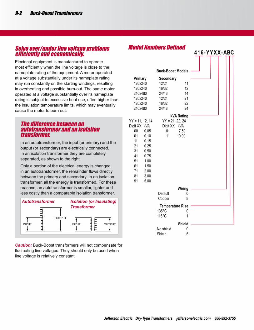
Model Numbers Defined416-YYXX-ABC
Buck-Boost Models
Primary Secondary 120x240 12/24 11 120x240 16/32 12 240x480 24/48 14 120x240 12/24 21 120x240 16/32 22 240x480 24/48 24
kVA RatingYY = 11, 12, 14 YY = 21, 22, 24Digit XX kVA Digit XX kVA 00 0.05 01 7.50 01 0.10 11 10.00 11 0.15 21 0.25 31 0.50 41 0.75 51 1.00 61 1.50 71 2.00 81 3.00 91 5.00
Wiring Default 0 Copper 8
Temperature Rise 135°C 0 115°C 1
Shield No shield 0 Shield 5
Solve over/under line voltage problems efficiently and economically.Electrical equipment is manufactured to operate mostefficientlywhenthelinevoltageisclosetothenameplate rating of the equipment. A motor operated at a voltage substantially under its nameplate rating may run constantly on the starting windings, resulting in overheating and possible burn-out. The same motor operated at a voltage substantially over its nameplate rating is subject to excessive heat rise, often higher than the insulation temperature limits, which may eventually cause the motor to burn out.
Caution: Buck-Boost transformers will not compensate for fluctuatinglinevoltages.Theyshouldonlybeusedwhenline voltage is relatively constant.
The difference between an autotransformer and an isolation transformer.In an autotransformer, the input (or primary) and the output (or secondary) are electrically connected. In an isolation transformer they are completely separated, as shown to the right.
Only a portion of the electrical energy is changed inanautotransformer,theremainderflowsdirectlybetween the primary and secondary. In an isolation transformer, all the energy is transformed. For these reasons, an autotransformer is smaller, lighter and less costly than a comparable isolation transformer.
Autotransformer Isolation (or Insulating) Transformer
9-3Buck-Boost Transformers
Follow These Five Easy Steps:1. Find the appropriate single-phase, three-phase delta
or three-phase wye table.
2.Readdownthevoltagecolumnandfindthenearestratio of required load voltage to line voltage for the application desired. (High and low voltage may be either input or output voltage depending on the circumstances.)
3. Reading horizontally across the line beginning with your application voltage ratio, locate in one of the kVA columns a kVA capacity equal to or larger than your load requirement.
4. Note the two digit number at the top of the kVA column listing the kVA capacity you require.
5. In the catalog number column, add these two digits to the catalog number next to the voltage ratio you found in step one.
How to Use the Buck-Boost Rapid Selector ChartsYou will need the following information:Line voltage:This can be determined by measuring the supply line voltage with a voltmeter.Load voltage:The voltage at which your equipment was designed to operate. Usually listed on the equipment nameplate. Load kVA or load amps:One of these will usually be listed on the nameplate. You do not need both.Supply line and equipment frequencies:This will be either 50 or 60 Hertz. The supply line frequency must be the same as the frequency of the equipment to be operated.Supply line and equipment phase:Either single-phase or three-phase. The line phase must be the same as the equipment.The type of electrical configuration:Delta or Wye.
Example:Assume the following information
1. A reasonably constant line voltage of 440 volts.
2. A required equipment voltage of 480 volts.
3. 26.0 kVA load capacity needed.
4. Single-phase line and equipment.
In the voltage column, 437 is closest to our line voltage of 440. The 480 high voltage meets our requirements exactly.Readinghorizontallyacrossthisline,find30.0kVA,theclosest larger kVA to our required 26.0.Going to the very top of this column, take the two digit number, 81, and add it on the end of the catalog number on the same line as our high/low voltage. The catalog number 416-14, with 81 added on the end, is 416-1481.
9-4
Jefferson Electric Dry-Type Transformers jeffersonelectric.com 800-892-3755
Buck-Boost Transformers
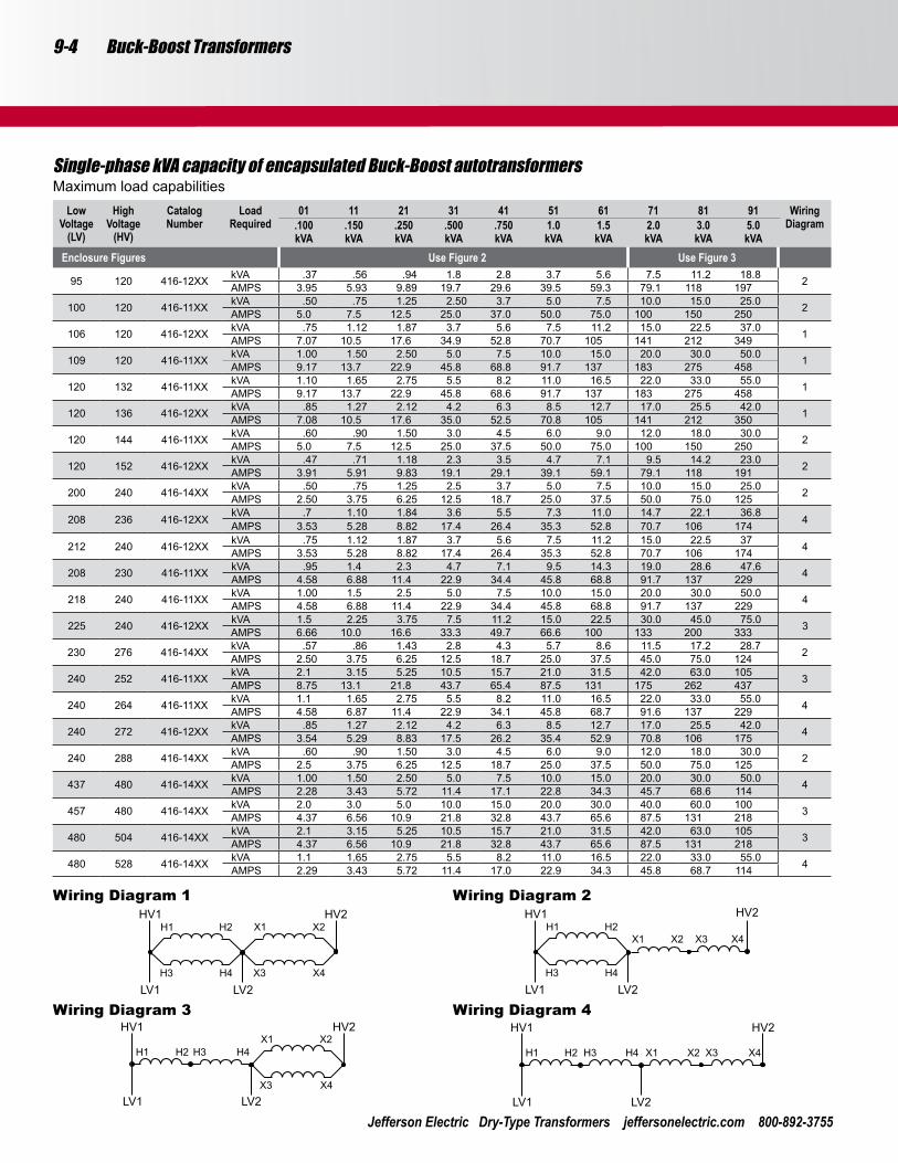
Single-phase kVA capacity of encapsulated Buck-Boost autotransformersMaximum load capabilities
Low Voltage
(LV)
High Voltage
(HV)
Catalog Number
Load Required
01.100kVA
11.150kVA
21.250kVA
31.500kVA
41.750kVA
511.0kVA
611.5kVA
712.0kVA
813.0kVA
915.0kVA
Wiring Diagram
Enclosure Figures Use Figure 2 Use Figure 3
95 120 416-12XX kVA .37 .56 .94 1.8 2.8 3.7 5.6 7.5 11.2 18.8 2AMPS 3.95 5.93 9.89 19.7 29.6 39.5 59.3 79.1 118 197
100 120 416-11XX kVA .50 .75 1.25 2.50 3.7 5.0 7.5 10.0 15.0 25.0 2AMPS 5.0 7.5 12.5 25.0 37.0 50.0 75.0 100 150 250
106 120 416-12XX kVA .75 1.12 1.87 3.7 5.6 7.5 11.2 15.0 22.5 37.0 1AMPS 7.07 10.5 17.6 34.9 52.8 70.7 105 141 212 349
109 120 416-11XX kVA 1.00 1.50 2.50 5.0 7.5 10.0 15.0 20.0 30.0 50.0 1AMPS 9.17 13.7 22.9 45.8 68.8 91.7 137 183 275 458
120 132 416-11XX kVA 1.10 1.65 2.75 5.5 8.2 11.0 16.5 22.0 33.0 55.0 1AMPS 9.17 13.7 22.9 45.8 68.6 91.7 137 183 275 458
120 136 416-12XX kVA .85 1.27 2.12 4.2 6.3 8.5 12.7 17.0 25.5 42.0 1AMPS 7.08 10.5 17.6 35.0 52.5 70.8 105 141 212 350
120 144 416-11XX kVA .60 .90 1.50 3.0 4.5 6.0 9.0 12.0 18.0 30.0 2AMPS 5.0 7.5 12.5 25.0 37.5 50.0 75.0 100 150 250
120 152 416-12XX kVA .47 .71 1.18 2.3 3.5 4.7 7.1 9.5 14.2 23.0 2AMPS 3.91 5.91 9.83 19.1 29.1 39.1 59.1 79.1 118 191
200 240 416-14XX kVA .50 .75 1.25 2.5 3.7 5.0 7.5 10.0 15.0 25.0 2AMPS 2.50 3.75 6.25 12.5 18.7 25.0 37.5 50.0 75.0 125
208 236 416-12XXkVA .7 1.10 1.84 3.6 5.5 7.3 11.0 14.7 22.1 36.8
4AMPS 3.53 5.28 8.82 17.4 26.4 35.3 52.8 70.7 106 174
212 240 416-12XX kVA .75 1.12 1.87 3.7 5.6 7.5 11.2 15.0 22.5 37 4AMPS 3.53 5.28 8.82 17.4 26.4 35.3 52.8 70.7 106 174
208 230 416-11XX kVA .95 1.4 2.3 4.7 7.1 9.5 14.3 19.0 28.6 47.6 4AMPS 4.58 6.88 11.4 22.9 34.4 45.8 68.8 91.7 137 229
218 240 416-11XX kVA 1.00 1.5 2.5 5.0 7.5 10.0 15.0 20.0 30.0 50.0 4AMPS 4.58 6.88 11.4 22.9 34.4 45.8 68.8 91.7 137 229
225 240 416-12XX kVA 1.5 2.25 3.75 7.5 11.2 15.0 22.5 30.0 45.0 75.0 3AMPS 6.66 10.0 16.6 33.3 49.7 66.6 100 133 200 333
230 276 416-14XX kVA .57 .86 1.43 2.8 4.3 5.7 8.6 11.5 17.2 28.7 2AMPS 2.50 3.75 6.25 12.5 18.7 25.0 37.5 45.0 75.0 124
240 252 416-11XX kVA 2.1 3.15 5.25 10.5 15.7 21.0 31.5 42.0 63.0 105 3AMPS 8.75 13.1 21.8 43.7 65.4 87.5 131 175 262 437
240 264 416-11XX kVA 1.1 1.65 2.75 5.5 8.2 11.0 16.5 22.0 33.0 55.0 4AMPS 4.58 6.87 11.4 22.9 34.1 45.8 68.7 91.6 137 229
240 272 416-12XX kVA .85 1.27 2.12 4.2 6.3 8.5 12.7 17.0 25.5 42.0 4AMPS 3.54 5.29 8.83 17.5 26.2 35.4 52.9 70.8 106 175
240 288 416-14XX kVA .60 .90 1.50 3.0 4.5 6.0 9.0 12.0 18.0 30.0 2AMPS 2.5 3.75 6.25 12.5 18.7 25.0 37.5 50.0 75.0 125
437 480 416-14XX kVA 1.00 1.50 2.50 5.0 7.5 10.0 15.0 20.0 30.0 50.0 4AMPS 2.28 3.43 5.72 11.4 17.1 22.8 34.3 45.7 68.6 114
457 480 416-14XX kVA 2.0 3.0 5.0 10.0 15.0 20.0 30.0 40.0 60.0 100 3AMPS 4.37 6.56 10.9 21.8 32.8 43.7 65.6 87.5 131 218
480 504 416-14XX kVA 2.1 3.15 5.25 10.5 15.7 21.0 31.5 42.0 63.0 105 3AMPS 4.37 6.56 10.9 21.8 32.8 43.7 65.6 87.5 131 218
480 528 416-14XX kVA 1.1 1.65 2.75 5.5 8.2 11.0 16.5 22.0 33.0 55.0 4AMPS 2.29 3.43 5.72 11.4 17.0 22.9 34.3 45.8 68.7 114
Wiring Diagram 1 Wiring Diagram 2
Wiring Diagram 3 Wiring Diagram 4
9-5Buck-Boost Transformers
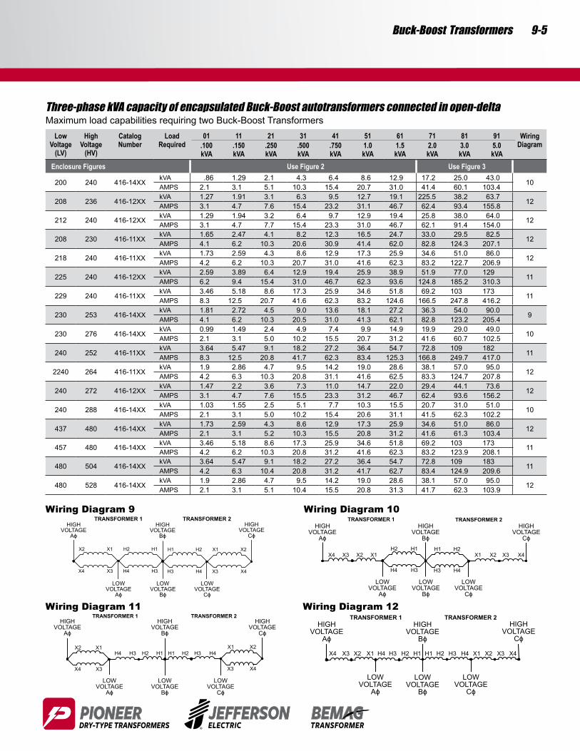
Three-phase kVA capacity of encapsulated Buck-Boost autotransformers connected in open-deltaMaximum load capabilities requiring two Buck-Boost Transformers
Low Voltage
(LV)
High Voltage
(HV)
Catalog Number
Load Required
01.100kVA
11.150kVA
21.250kVA
31.500kVA
41.750kVA
511.0kVA
611.5kVA
712.0kVA
813.0kVA
915.0kVA
Wiring Diagram
Enclosure Figures Use Figure 2 Use Figure 3
200 240 416-14XXkVA .86 1.29 2.1 4.3 6.4 8.6 12.9 17.2 25.0 43.0
10AMPS 2.1 3.1 5.1 10.3 15.4 20.7 31.0 41.4 60.1 103.4
208 236 416-12XXkVA 1.27 1.91 3.1 6.3 9.5 12.7 19.1 225.5 38.2 63.7
12AMPS 3.1 4.7 7.6 15.4 23.2 31.1 46.7 62.4 93.4 155.8
212 240 416-12XXkVA 1.29 1.94 3.2 6.4 9.7 12.9 19.4 25.8 38.0 64.0 12AMPS 3.1 4.7 7.7 15.4 23.3 31.0 46.7 62.1 91.4 154.0
208 230 416-11XXkVA 1.65 2.47 4.1 8.2 12.3 16.5 24.7 33.0 29.5 82.5
12AMPS 4.1 6.2 10.3 20.6 30.9 41.4 62.0 82.8 124.3 207.1
218 240 416-11XXkVA 1.73 2.59 4.3 8.6 12.9 17.3 25.9 34.6 51.0 86.0
12AMPS 4.2 6.2 10.3 20.7 31.0 41.6 62.3 83.2 122.7 206.9
225 240 416-12XXkVA 2.59 3.89 6.4 12.9 19.4 25.9 38.9 51.9 77.0 129
11AMPS 6.2 9.4 15.4 31.0 46.7 62.3 93.6 124.8 185.2 310.3
229 240 416-11XXkVA 3.46 5.18 8.6 17.3 25.9 34.6 51.8 69.2 103 173
11AMPS 8.3 12.5 20.7 41.6 62.3 83.2 124.6 166.5 247.8 416.2
230 253 416-14XXkVA 1.81 2.72 4.5 9.0 13.6 18.1 27.2 36.3 54.0 90.0
9AMPS 4.1 6.2 10.3 20.5 31.0 41.3 62.1 82.8 123.2 205.4
230 276 416-14XXkVA 0.99 1.49 2.4 4.9 7.4 9.9 14.9 19.9 29.0 49.0
10AMPS 2.1 3.1 5.0 10.2 15.5 20.7 31.2 41.6 60.7 102.5
240 252 416-11XXkVA 3.64 5.47 9.1 18.2 27.2 36.4 54.7 72.8 109 182
11AMPS 8.3 12.5 20.8 41.7 62.3 83.4 125.3 166.8 249.7 417.0
2240 264 416-11XXkVA 1.9 2.86 4.7 9.5 14.2 19.0 28.6 38.1 57.0 95.0
12AMPS 4.2 6.3 10.3 20.8 31.1 41.6 62.5 83.3 124.7 207.8
240 272 416-12XXkVA 1.47 2.2 3.6 7.3 11.0 14.7 22.0 29.4 44.1 73.6
12AMPS 3.1 4.7 7.6 15.5 23.3 31.2 46.7 62.4 93.6 156.2
240 288 416-14XXkVA 1.03 1.55 2.5 5.1 7.7 10.3 15.5 20.7 31.0 51.0
10AMPS 2.1 3.1 5.0 10.2 15.4 20.6 31.1 41.5 62.3 102.2
437 480 416-14XXkVA 1.73 2.59 4.3 8.6 12.9 17.3 25.9 34.6 51.0 86.0
12AMPS 2.1 3.1 5.2 10.3 15.5 20.8 31.2 41.6 61.3 103.4
457 480 416-14XXkVA 3.46 5.18 8.6 17.3 25.9 34.6 51.8 69.2 103 173 11AMPS 4.2 6.2 10.3 20.8 31.2 41.6 62.3 83.2 123.9 208.1
480 504 416-14XXkVA 3.64 5.47 9.1 18.2 27.2 36.4 54.7 72.8 109 183
11AMPS 4.2 6.3 10.4 20.8 31.2 41.7 62.7 83.4 124.9 209.6
480 528 416-14XXkVA 1.9 2.86 4.7 9.5 14.2 19.0 28.6 38.1 57.0 95.0
12AMPS 2.1 3.1 5.1 10.4 15.5 20.8 31.3 41.7 62.3 103.9
Wiring Diagram 9 Wiring Diagram 10
Wiring Diagram 11 Wiring Diagram 12

9-6
Jefferson Electric Dry-Type Transformers jeffersonelectric.com 800-892-3755
Buck-Boost Transformers
Three-phase kVA capacity of encapsulated Buck-Boost autotransformers connected in WyeMaximum load capabilities requiring three Buck-Boost Transformers
Low Voltage
(LV)
High Voltage
(HV)
Catalog Number
Load Required
01.100kVA
11.150kVA
21.250kVA
31.500kVA
41.750kVA
511.0kVA
611.5kVA
712.0kVA
813.0kVA
915.0kVA
Wiring Diagram
Enclosure Figures Use Figure 2 Use Figure 3
164 208 416-12XX kVA 1.1 1.7 2.8 5.6 8.4 11.2 16.8 22.0 34.0 56.0 6AMPS 3.89 5.89 9.79 18.9 29.4 38.9 58.9 78.9 117 197
173 208 416-11XX kVA 1.5 2.2 3.7 7.5 11.2 15.0 22.5 30.0 45.5 75.0 6AMPS 5.0 7.5 12.5 25.0 37.0 50.0 75.0 100 150 250
183 208 416-12XX kVA 2.2 3.3 5.6 11.2 16.8 22.5 33.7 45.0 67.0 112 5AMPS 7.07 10.5 17.6 34.9 52.8 70.7 105 141 212 354
189 208 416-11XX kVA 3.0 4.5 7.5 15.0 22.5 30.0 45.0 60.0 90.0 150 5AMPS 9.17 13.7 22.9 45.8 68.8 91.7 137 183 275 458
208 229 416-11XX kVA 3.3 4.9 8.2 16.5 24.7 33.0 49.5 66.0 99.0 165 5AMPS 9.17 13.7 22.9 45.8 68.8 91.7 137 183 275 458
208 235 416-12XX kVA 2.5 3.8 6.3 12.7 19.1 25.5 38.2 51.0 76.5 127 5AMPS 7.08 10.5 17.6 35.0 52.5 70.8 105 141 212 350
208 249 416-11XX kVA 1.8 2.7 4.5 9.0 13.5 18.0 27.0 36.0 54.0 90.0 6AMPS 5.0 7.5 12.5 25.0 37.5 50.0 75.0 100 150 250
208 263 416-12XX kVA 1.4 2.1 3.5 7.1 10.6 14.2 21.4 28.0 42.0 71.0 6AMPS 3.91 5.91 9.83 19.1 29.1 39.1 59.1 79.1 118 191
346 416 416-14XX kVA 1.5 2.2 3.7 7.5 11.2 15.0 22.5 30.0 45.0 75.0 6AMPS 2.5 3.75 6.25 12.5 18.5 25.0 37.5 50.0 75.0 125
367 416 416-12XX kVA 2.2 3.3 5.6 11.2 16.8 22.5 33.7 45.0 67.0 112 8AMPS 3.53 5.28 8.82 17.4 26.4 35.3 52.8 70.7 106 174
378 416 416-12XX kVA 3.0 4.5 7.5 15.0 22.5 30.0 45.0 60.0 90.0 150 8AMPS 4.58 6.88 11.4 22.9 34.4 45.8 68.8 91.7 137 229
390 416 416-11XXkVA 4.5 6.7 11.2 22.5 33.7 45.0 67.5 90.0 135 225
7AMPS 6.66 10.0 16.6 33.3 49.7 66.6 100 133 200 333
397 416 416-11XX kVA 6.0 9.0 15.0 30.0 45.0 60.0 90.0 120 180 300 7AMPS 8.73 13.1 21.8 43.6 65.5 87.3 131 174 262 436
398 438 416-12XX kVA 3.1 4.7 7.8 15.7 23.6 31.5 47.2 63.0 94.0 157 5AMPS 4.56 6.82 11.3 22.6 33.9 45.6 68.2 91.3 136 229
398 478 416-14XX kVA 1.7 2.5 4.3 8.6 12.9 17.2 25.9 34.0 51.0 86.0 6AMPS 2.50 3.75 6.25 12.5 18.7 25.0 37.5 50.0 75.0 125
416 437 416-11XX kVA 6.3 9.4 15.7 31.5 47.2 63.0 94.5 126 189 315 7AMPS 8.75 13.1 21.8 43.7 65.4 87.5 131 175 262 437
416 443 416-11XX kVA 4.8 7.2 12.0 24.0 36.0 48.0 72.0 96.0 144 240 7AMPS 6.66 10.0 16.6 33.3 50.0 66.6 100 133 200 333
416 457 416-12XX kVA 3.3 4.9 8.2 16.5 24.7 33.0 49.5 66.0 99.0 165 8AMPS 4.58 6.87 11.4 22.9 34.1 45.8 68.7 91.6 137 229
416 471 416-14XX kVA 2.5 3.8 6.3 12.7 19.1 25.5 38.2 51.0 76.5 127 8AMPS 3.54 5.29 8.83 17.5 26.2 35.4 52.9 70.8 106 175
416 498 416-14XX kVA 1.8 2.7 4.5 9.0 13.5 18.0 27.0 36.0 54.0 90.0 6AMPS 2.5 3.75 6.25 12.5 18.7 25.0 37.5 50.0 75.0 125
Wiring Diagram 5 Wiring Diagram 6
Wiring Diagram 7 Wiring Diagram 8
9-7Buck-Boost Transformers
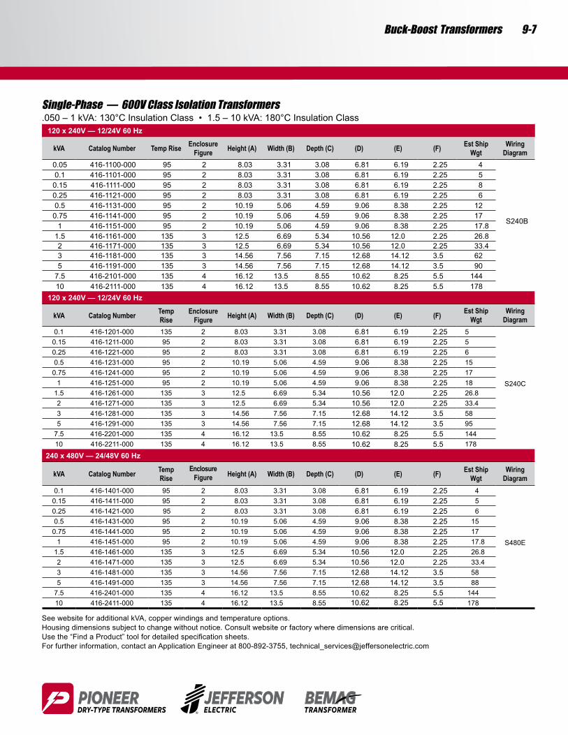
Single-Phase — 600V Class Isolation Transformers.050 – 1 kVA: 130°C Insulation Class • 1.5 – 10 kVA: 180°C Insulation Class
120 x 240V — 12/24V 60 Hz
kVA Catalog Number Temp Rise EnclosureFigure Height (A) Width (B) Depth (C) (D) (E) (F) Est Ship
WgtWiring
Diagram0.05 416-1100-000 95 2 8.03 3.31 3.08 6.81 6.19 2.25 4
S240B
0.1 416-1101-000 95 2 8.03 3.31 3.08 6.81 6.19 2.25 50.15 416-1111-000 95 2 8.03 3.31 3.08 6.81 6.19 2.25 80.25 416-1121-000 95 2 8.03 3.31 3.08 6.81 6.19 2.25 60.5 416-1131-000 95 2 10.19 5.06 4.59 9.06 8.38 2.25 120.75 416-1141-000 95 2 10.19 5.06 4.59 9.06 8.38 2.25 17
1 416-1151-000 95 2 10.19 5.06 4.59 9.06 8.38 2.25 17.81.5 416-1161-000 135 3 12.5 6.69 5.34 10.56 12.0 2.25 26.82 416-1171-000 135 3 12.5 6.69 5.34 10.56 12.0 2.25 33.43 416-1181-000 135 3 14.56 7.56 7.15 12.68 14.12 3.5 625 416-1191-000 135 3 14.56 7.56 7.15 12.68 14.12 3.5 90
7.5 416-2101-000 135 4 16.12 13.5 8.55 10.62 8.25 5.5 14410 416-2111-000 135 4 16.12 13.5 8.55 10.62 8.25 5.5 178
120 x 240V — 12/24V 60 Hz
kVA Catalog Number Temp Rise
EnclosureFigure Height (A) Width (B) Depth (C) (D) (E) (F) Est Ship
WgtWiring
Diagram0.1 416-1201-000 135 2 8.03 3.31 3.08 6.81 6.19 2.25 5
S240C
0.15 416-1211-000 95 2 8.03 3.31 3.08 6.81 6.19 2.25 50.25 416-1221-000 95 2 8.03 3.31 3.08 6.81 6.19 2.25 60.5 416-1231-000 95 2 10.19 5.06 4.59 9.06 8.38 2.25 150.75 416-1241-000 95 2 10.19 5.06 4.59 9.06 8.38 2.25 17
1 416-1251-000 95 2 10.19 5.06 4.59 9.06 8.38 2.25 181.5 416-1261-000 135 3 12.5 6.69 5.34 10.56 12.0 2.25 26.82 416-1271-000 135 3 12.5 6.69 5.34 10.56 12.0 2.25 33.43 416-1281-000 135 3 14.56 7.56 7.15 12.68 14.12 3.5 585 416-1291-000 135 3 14.56 7.56 7.15 12.68 14.12 3.5 95
7.5 416-2201-000 135 4 16.12 13.5 8.55 10.62 8.25 5.5 14410 416-2211-000 135 4 16.12 13.5 8.55 10.62 8.25 5.5 178
240 x 480V — 24/48V 60 Hz
kVA Catalog Number Temp Rise
EnclosureFigure Height (A) Width (B) Depth (C) (D) (E) (F) Est Ship
WgtWiring
Diagram0.1 416-1401-000 95 2 8.03 3.31 3.08 6.81 6.19 2.25 4
S480E
0.15 416-1411-000 95 2 8.03 3.31 3.08 6.81 6.19 2.25 50.25 416-1421-000 95 2 8.03 3.31 3.08 6.81 6.19 2.25 60.5 416-1431-000 95 2 10.19 5.06 4.59 9.06 8.38 2.25 15
0.75 416-1441-000 95 2 10.19 5.06 4.59 9.06 8.38 2.25 171 416-1451-000 95 2 10.19 5.06 4.59 9.06 8.38 2.25 17.8
1.5 416-1461-000 135 3 12.5 6.69 5.34 10.56 12.0 2.25 26.82 416-1471-000 135 3 12.5 6.69 5.34 10.56 12.0 2.25 33.43 416-1481-000 135 3 14.56 7.56 7.15 12.68 14.12 3.5 585 416-1491-000 135 3 14.56 7.56 7.15 12.68 14.12 3.5 88
7.5 416-2401-000 135 4 16.12 13.5 8.55 10.62 8.25 5.5 14410 416-2411-000 135 4 16.12 13.5 8.55 10.62 8.25 5.5 178
See website for additional kVA, copper windings and temperature options. Housing dimensions subject to change without notice. Consult website or factory where dimensions are critical.Usethe“FindaProduct”toolfordetailedspecificationsheets.For further information, contact an Application Engineer at 800-892-3755, [email protected]
9-8
Jefferson Electric Dry-Type Transformers jeffersonelectric.com 800-892-3755
Buck-Boost Transformers
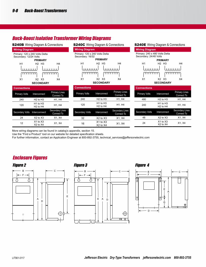
Enclosure Figures.Figure 2 Figure 4Figure 3
Buck-Boost Isolation Transformer Wiring Diagrams
More wiring diagrams can be found in catalog’s appendix, section 15.Usethe“FindaProduct”toolonourwebsitefordetailedspecificationsheets.For further information, contact an Application Engineer at 800-892-3755, [email protected]
S240B Wiring Diagram & ConnectionsWiring DiagramPrimary: 120 x 240 Volts DeltaSecondary: 12/24 Volts
PRIMARY
SECONDARY
Connections
Primary Volts Interconnect Primary Lines Connect To
240 H2 to H3 H1, H4
120 H1 to H3H2 to H4 H1, H4
Secondary Volts InterconnectSecondary Lines
Connect To24 X2 to X3 X1, X4
12 X1 to X3X2 to X4 X1, X4
S240C Wiring Diagram & Connections
Connections
Primary Volts Interconnect Primary Lines Connect To
240 H2 to H3 H1, H4
120 H1 to H3H2 to H4 H1. H4
Secondary Volts Interconnect Secondary Lines Connect To
32 X2 to X3 X1, X4
16 X1 to X3X2 to X4 X1, X4
Wiring DiagramPrimary: 120 x 240 Volts DeltaSecondary: 16/32
PRIMARY
SECONDARY
S240E Wiring Diagram & Connections
Connections
Primary Volts Interconnect Primary Lines Connect To
480 H2 to H3 H1, H4
240 H1 to H3H2 to H4 H1, H4
Secondary Volts Interconnect Secondary Lines Connect To
48 X2 to X3 X1, X4
24 X1 to X3X2 to X4 X1, X4
Wiring DiagramPrimary: 240 x 480 Volts DeltaSecondary: 24/48 Volts
PRIMARY
SECONDARY
LIT901-0117