Embed Size (px)
Citation preview
Buck-Boost » Transformers
AmericAn rotAry N59W16600 Greenway Circle, Menomonee Falls, WI 53051
©2014 American Rotary. All Rights Reserved
AmericanRotary.com 888.743.6832
Buck-Boost Transformers - Questions & Answers
1. What is a buck-boost transformer?
Buck-boost transformers are small single phase transformers designed to lower (buck) or raise (boost) line voltage from 5-20%. The most common applications for buck-boost transformers include boosting 208 volts to 230 or 240 volts for air conditioning systems, boosting 110 to 120 volts and 240 to 277 volts for lighting applications, heating systems and induction motors of all types. Many applications exist where supply voltages are frequently above or below nominal.
Buck-boost transformers are conventional low voltage, single phase distribution transformers, with standard primary voltages of 120, 240 or 480 volts, and secondary voltages of 12, 16, 24, 32 or 48 volts. They are available in sizes ranging from 50 VA to 10,000 VA. The primary and secondary are wired together to form a single-winding autotransformer. Utilizing the additive and subtractive polarity, small amounts of voltage are either added or subtracted from a distribution circuit.
2. How does a buck-boost transformer differ from an isolating transformer?
A buck-boost transformer is manufactured as an isolating transformer, with separable primary and secondary, and is shipped from the factory in that configuration. When the end user at site connects it, the primary is connected to the secondary changing the transformer’s electrical characteristics to those of an autotransformer. This provides the smaller voltage correction that is typical of buck-boost. The primary and secondary windings are no longer isolated as they are connected together.
3. What is the difference between a buck-boost transformer and an autotransformer?
As noted above, when the primary and secondary are connected together to buck or boost voltage, the transformer becomes an autotransformer. If the connection between the primary and secondary winding is not made, then the unit remains as an isolation transformer.
Applications
4. Why are they used?A buck-boost transformer is a simple and effective way of correcting off-standard voltages. Electrical and electronic equipment is designed to operate within a standard tolerance of nominal supply voltages. When the supply voltage is consistently too high or low - typically more than 10%, the equipment will operate below peak efficiency.
5. Can buck-boost transformers be used to power low voltage circuits?
Installed as two-winding, isolation transformers, these units can be used to power low voltage circuits including control, lighting circuits, or other low voltage applications that require 12, 16, 24, 32 or 48 volts output, consistent with the secondary of these designs. The unit is connected as an isolating transformer and the nameplate kVA rating is the transformer’s capacity.
Buck-Boost » Transformers
AmericAn rotAry N59W16600 Greenway Circle, Menomonee Falls, WI 53051
©2014 American Rotary. All Rights Reserved
AmericanRotary.com 888.743.6832
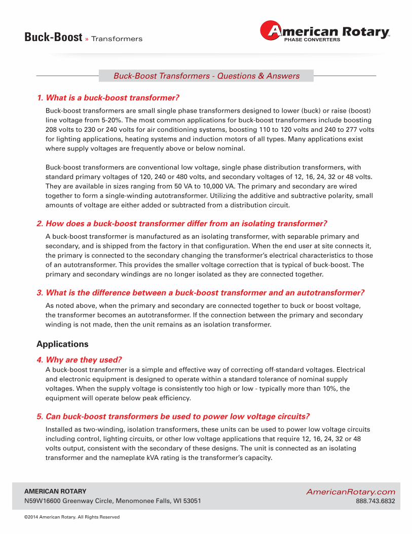
Single Phase Connection Diagrams
Buck-Boost » Transformers
SECTION 2
93
SE
CTIO
N 2
BUCK-BOOST TRANSFORMERS
LowVoltage
HighVoltage
H4H2
H3
H1
X1
X3
X2
X4
LowVoltage
HighVoltage
H4H2
H3
H1
X1
X3
X2
X4
LowVoltage
HighVoltage
H4H2
H3
H1
X1
X3
X2
X4
LowVoltage
HighVoltage
H4H2
H3
H1
X1
X3
X2
X4
© Hammond Power Solutions Inc. Data subject to change without notice.
Single Phase Connection Diagrams
ConnectionDiagram #2
ConnectionDiagram #3
ConnectionDiagram #4
ConnectionDiagram #1
AmericAn rotAry N59W16600 Greenway Circle, Menomonee Falls, WI 53051
©2014 American Rotary. All Rights Reserved
AmericanRotary.com 888.743.6832
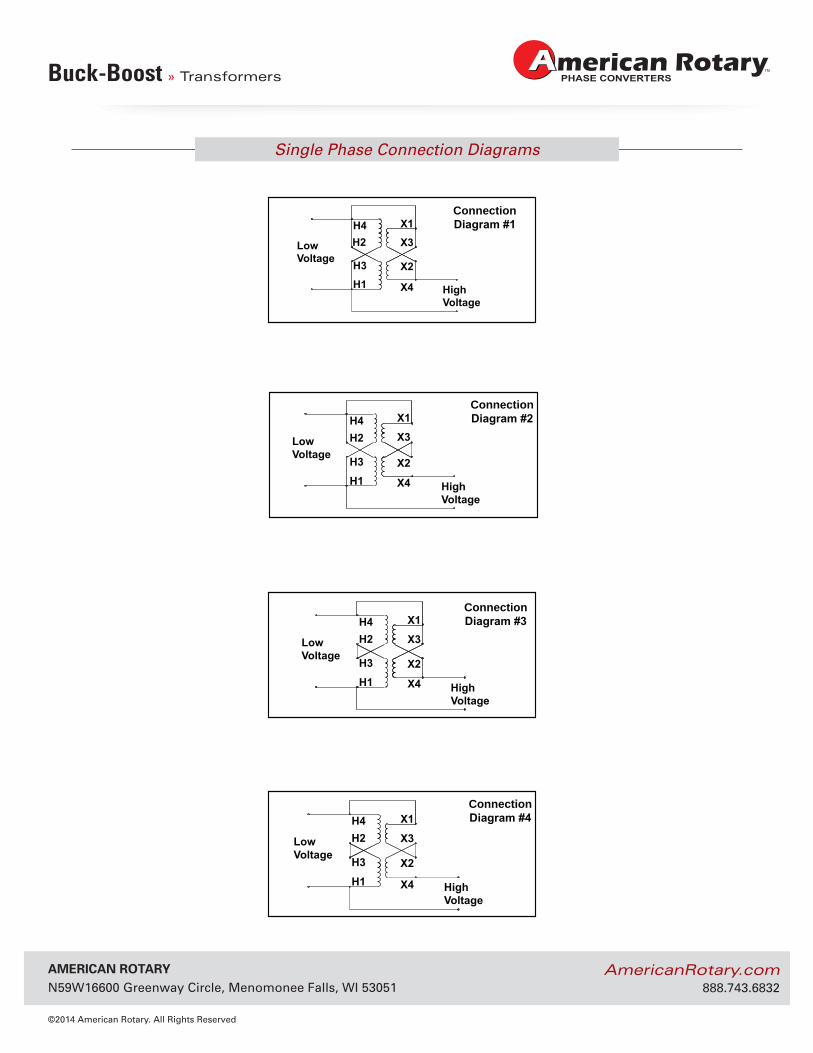
NEMA 3R Enclosure Dimensional Drawings
Buck-Boost » Transformers
262
GENERAL INFORMATIONG
ENER
AL
INFO
RM
ATIO
N
CaseStyle Fig #
Dimensions in InchesA B C D E F G H J K1 L M N P R
NQ0 1 3.75 5.25 7.25 2.50 5.63 6.25 1.50 2.00 -- 0.88 -- -- 0.22 1.25 --NQ1 1 4.50 5.75 7.25 3.13 5.63 6.25 1.50 2.00 0.81 0.88 -- -- 0.22 1.25 --NQ2 1 5.00 4.75 9.25 3.88 7.75 8.25 1.50 2.00 1.00 0.88 X 1.13 X 1.38 -- -- 0.22 1.25 --NQ3 1 5.88 5.50 10.50 4.13 8.25 9.00 1.50 2.00 1.25 0.88 X 1.13 X 1.38 -- -- 0.28 1.25 --NQ4 1 7.00 6.50 11.75 5.38 9.50 10.25 1.75 2.00 1.50 0.88 X 1.13 X 1.38 -- -- 0.28 1.25 --NQ5 2 10.00 7.75 17.25 7.38 15.38 15.25 2.375 2.00 4.00 1.13 X 1.38 6.00 0.75 0.44 1.25 1.68
NQ6A 2 12.25 9.25 17.63 9.38 14.88 15.56 2.00 2.00 5.00 1.38 X 2.50 8.00 0.75 0.44 2.00 1.68NQ6 2 12.25 9.25 20.88 9.38 18.13 18.88 2.00 2.00 5.00 1.38 X 2.50 8.00 0.75 0.44 2.00 1.68NQ7 2 14.50 10.75 21.38 11.63 18.63 19.38 2.00 2.00 6.00 1.38 X 2.50 10.00 0.75 0.44 2.00 1.81NQ8 2 14.50 10.75 27.38 11.13 24.50 24.88 2.00 2.00 6.00 1.38 X 2.50 10.00 0.75 0.56 2.00 1.81
© Hammond Power Solutions Inc. Data subject to change without notice.
‘NQ’ SERIES ENCLOSURESNEMA 3R ENCLOSURE DIMENSIONAL DRAWINGS
OptiOnal StainlESS StEEl EnclOSurES arE availablE.1 Knockout (K) sizes are actual diameters of knockout, not conduit sizes. Refer to table on page 260 for conduit sizes.
A
C
G
F
BØM
H
.34
LØN
ØN D
J
E
K (K.O.)
K (K.O.)
P
R
FRONT VIEW SIDE VIEW BACK VIEW
BA
CK
Figure 2
A
C
B
F
G
K (K.O.)
.39
H
D
E
J
ØN
ØNK (K.O.)
P
A/2
FRONT VIEW SIDE VIEW BACK VIEW
BA
CK
Figure 1
‘NQ’ Series Enclosures

AmericAn rotAry N59W16600 Greenway Circle, Menomonee Falls, WI 53051
©2014 American Rotary. All Rights Reserved
AmericanRotary.com 888.743.6832
Single Phase Specification Tables
Buck-Boost » Transformers
90
SECTION 2S
EC
TIO
N 2
HPS Universal™
© Hammond Power Solutions Inc. Data subject to change without notice.
Single Phase Specification Tables
PrimaryVoltageSecondaryVoltage
120 X 240
12 X 24
Group A
50/60 Hertz
PrimaryVoltageSecondaryVoltage
120 X 240
16 X 32
Group B
50/60 Hertz
VA CatalogNumber
CaseStyle
(Pages 262)
Approx. Dimensions(Inches) Approx.
Weight(Lbs.)
Mtg TypeW - WallWidth Depth Height
50 QC05ERCB NQ0 3.75 5.25 7.25 6 W100 QC10ERCB NQ0 3.75 5.25 7.25 7 W150 QC15ERCB NQ0 3.75 5.25 7.25 8 W200 QC20ERCB NQ1 4.50 5.75 7.25 11 W250 QC25ERCB NQ1 4.50 5.75 7.25 13 W350 QC35ERCB NQ1 4.50 5.75 7.25 14 W500 QC50ERCB NQ2 5.00 4.75 9.25 15 W750 QC75ERCB NQ2 5.00 4.75 9.25 18 W1000 Q1C0ERCB NQ3 5.88 5.50 10.50 25 W1500 Q1C5ERCF NQ4 7.00 6.50 11.75 36 W2000 Q002ERCF NQ4 7.00 6.50 11.75 46 W3000 Q003ERCF NQ5 10.00 7.75 17.25 65 W5000 Q005ERCF NQ5 10.00 7.75 17.25 105 W
VA CatalogNumber
CaseStyle
(Pages 262)
Approx. Dimensions(Inches) Approx.
Weight(Lbs.)
Mtg TypeW - WallWidth Depth Height
50 QC05ESCB NQ0 3.75 5.25 7.25 6 W100 QC10ESCB NQ0 3.75 5.25 7.25 7 W150 QC15ESCB NQ0 3.75 5.25 7.25 8 W200 QC20ESCB NQ1 4.50 5.75 7.25 11 W250 QC25ESCB NQ1 4.50 5.75 7.25 13 W350 QC35ESCB NQ1 4.50 5.75 7.25 14 W500 QC50ESCB NQ2 5.00 4.75 9.25 15 W750 QC75ESCB NQ2 5.00 4.75 9.25 18 W1000 Q1C0ESCB NQ3 5.88 5.50 10.50 25 W1500 Q1C5ESCF NQ4 7.00 6.50 11.75 36 W2000 Q002ESCF NQ4 7.00 6.50 11.75 46 W3000 Q003ESCF NQ5 10.00 7.75 17.25 65 W5000 Q005ESCF NQ5 10.00 7.75 17.25 105 W
AmericAn rotAry N59W16600 Greenway Circle, Menomonee Falls, WI 53051
©2014 American Rotary. All Rights Reserved
AmericanRotary.com 888.743.6832
Single Phase Specification Tables
Buck-Boost » Transformers
SECTION 2
91
SE
CTIO
N 2
BUCK-BOOST TRANSFORMERS
© Hammond Power Solutions Inc. Data subject to change without notice.
Single Phase Specification Tables
PrimaryVoltageSecondaryVoltage
240 X 480
24 X 48
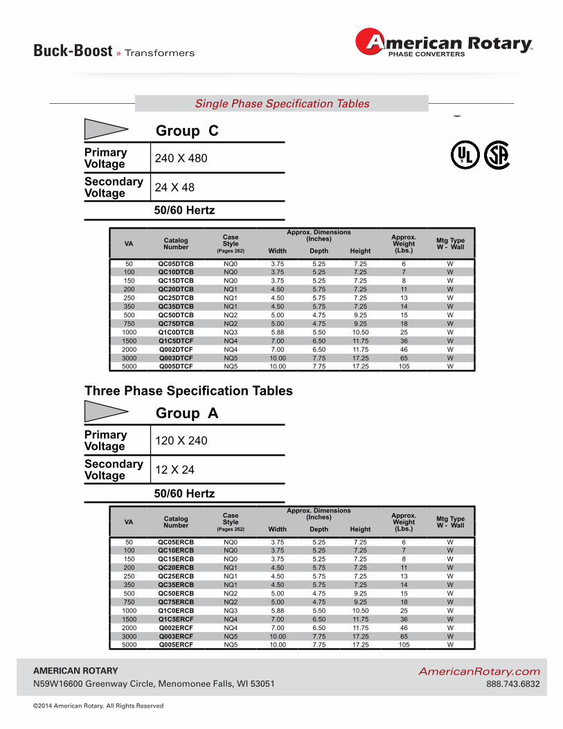
Group C
50/60 Hertz
Three Phase Specification Tables
PrimaryVoltageSecondaryVoltage
120 X 240
12 X 24
Group A
50/60 Hertz
VA CatalogNumber
CaseStyle
(Pages 262)
Approx. Dimensions(Inches) Approx.
Weight(Lbs.)
Mtg TypeW - WallWidth Depth Height
50 QC05DTCB NQ0 3.75 5.25 7.25 6 W100 QC10DTCB NQ0 3.75 5.25 7.25 7 W150 QC15DTCB NQ0 3.75 5.25 7.25 8 W200 QC20DTCB NQ1 4.50 5.75 7.25 11 W250 QC25DTCB NQ1 4.50 5.75 7.25 13 W350 QC35DTCB NQ1 4.50 5.75 7.25 14 W500 QC50DTCB NQ2 5.00 4.75 9.25 15 W750 QC75DTCB NQ2 5.00 4.75 9.25 18 W1000 Q1C0DTCB NQ3 5.88 5.50 10.50 25 W1500 Q1C5DTCF NQ4 7.00 6.50 11.75 36 W2000 Q002DTCF NQ4 7.00 6.50 11.75 46 W3000 Q003DTCF NQ5 10.00 7.75 17.25 65 W5000 Q005DTCF NQ5 10.00 7.75 17.25 105 W
VA CatalogNumber
CaseStyle
(Pages 262)
Approx. Dimensions(Inches) Approx.
Weight(Lbs.)
Mtg TypeW - WallWidth Depth Height
50 QC05ERCB NQ0 3.75 5.25 7.25 6 W100 QC10ERCB NQ0 3.75 5.25 7.25 7 W150 QC15ERCB NQ0 3.75 5.25 7.25 8 W200 QC20ERCB NQ1 4.50 5.75 7.25 11 W250 QC25ERCB NQ1 4.50 5.75 7.25 13 W350 QC35ERCB NQ1 4.50 5.75 7.25 14 W500 QC50ERCB NQ2 5.00 4.75 9.25 15 W750 QC75ERCB NQ2 5.00 4.75 9.25 18 W1000 Q1C0ERCB NQ3 5.88 5.50 10.50 25 W1500 Q1C5ERCF NQ4 7.00 6.50 11.75 36 W2000 Q002ERCF NQ4 7.00 6.50 11.75 46 W3000 Q003ERCF NQ5 10.00 7.75 17.25 65 W5000 Q005ERCF NQ5 10.00 7.75 17.25 105 W
AmericAn rotAry N59W16600 Greenway Circle, Menomonee Falls, WI 53051
©2014 American Rotary. All Rights Reserved
AmericanRotary.com 888.743.6832
Why Use Buck-Boost Transformers?
Buck-Boost » Transformers
82
SECTION 2S
EC
TIO
N 2
HPS Universal™
BUCK-BOOST STANDARD SPECIFICATIONS
© Hammond Power Solutions Inc. Data subject to change without notice.
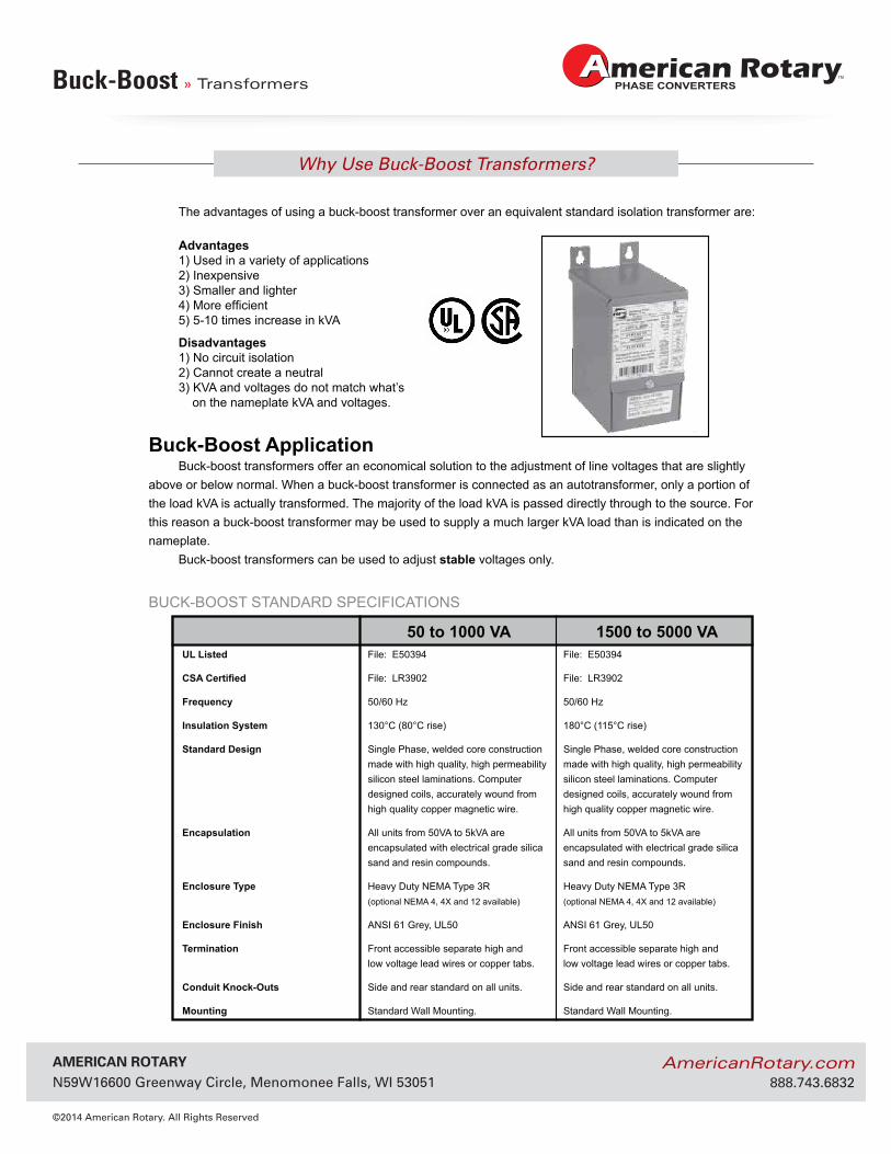
Why Use Buck-Boost Transformers?The advantages of using a buck-boost transformer over an equivalent standard isolation transformer are:
Advantages1) Used in a variety of applications2) Inexpensive3) Smaller and lighter4) More efficient 5) 5-10 times increase in kVA
Disadvantages1) No circuit isolation2) Cannot create a neutral3) KVA and voltages do not match what’s on the nameplate kVA and voltages.
Buck-Boost ApplicationBuck-boost transformers offer an economical solution to the adjustment of line voltages that are slightly
above or below normal. When a buck-boost transformer is connected as an autotransformer, only a portion of the load kVA is actually transformed. The majority of the load kVA is passed directly through to the source. For this reason a buck-boost transformer may be used to supply a much larger kVA load than is indicated on the nameplate.
Buck-boost transformers can be used to adjust stable voltages only.
UL Listed File: E50394 File: E50394
CSA Certified File: LR3902 File: LR3902
Frequency 50/60 Hz 50/60 Hz
Insulation System 130°C (80°C rise) 180°C (115°C rise)
Standard Design Single Phase, welded core construction Single Phase, welded core construction made with high quality, high permeability made with high quality, high permeability silicon steel laminations. Computer silicon steel laminations. Computer designed coils, accurately wound from designed coils, accurately wound from high quality copper magnetic wire. high quality copper magnetic wire.
Encapsulation All units from 50VA to 5kVA are All units from 50VA to 5kVA are encapsulated with electrical grade silica encapsulated with electrical grade silica sand and resin compounds. sand and resin compounds.
Enclosure Type Heavy Duty NEMA Type 3R Heavy Duty NEMA Type 3R (optional NEMA 4, 4X and 12 available) (optional NEMA 4, 4X and 12 available)
Enclosure Finish ANSI 61 Grey, UL50 ANSI 61 Grey, UL50
Termination Front accessible separate high and Front accessible separate high and low voltage lead wires or copper tabs. low voltage lead wires or copper tabs.
Conduit Knock-Outs Side and rear standard on all units. Side and rear standard on all units.
Mounting Standard Wall Mounting. Standard Wall Mounting.
50 to 1000 VA 1500 to 5000 VA
Single & Three Phase
» Transformers
AmericAn rotAry N59W16600 Greenway Circle, Menomonee Falls, WI 53051
©2014 American Rotary. All Rights Reserved
AmericanRotary.com 888.743.6832
General Purpose
Single & Three Phase » TransformersSEC
TION
7
For termination details see page 275.175
For accessories see pages 271 to 274.
SECTION 7 ENERGY EFFICIENT GENERAL PURPOSE DISTRIBUTION
© Hammond Power Solutions Inc. Data subject to change without notice.
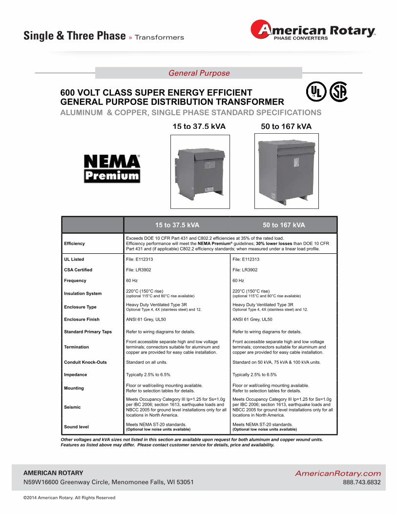
15 to 37.5 kVA 50 to 167 kVA
EfficiencyExceeds DOE 10 CFR Part 431 and C802.2 efficiencies at 35% of the rated load.Efficiency performance will meet the NEMA Premium® guidelines; 30% lower losses than DOE 10 CFR Part 431 and (if applicable) C802.2 efficiency standards; when measured under a linear load profile.
UL Listed File: E112313 File: E112313
CSA Certified File: LR3902 File: LR3902
Frequency 60 Hz 60 Hz
Insulation System 220°C (150°C rise)(optional 115°C and 80°C rise available)
220°C (150°C rise)(optional 115°C and 80°C rise available)
Enclosure Type Heavy Duty Ventilated Type 3ROptional Type 4, 4X (stainless steel) and 12.
Heavy Duty Ventilated Type 3ROptional Type 4, 4X (stainless steel) and 12.
Enclosure Finish ANSI 61 Grey, UL50 ANSI 61 Grey, UL50
Standard Primary Taps Refer to wiring diagrams for details. Refer to wiring diagrams for details.
TerminationFront accessible separate high and low voltage terminals; connectors suitable for aluminum and copper are provided for easy cable installation.
Front accessible separate high and low voltage terminals; connectors suitable for aluminum and copper are provided for easy cable installation.
Conduit Knock-Outs Standard on all units. Standard on 50 kVA, 75 kVA & 100 kVA units.
Impedance Typically 2.5% to 6.5% Typically 2.5% to 6.5%
Mounting Floor or wall/ceiling mounting available.Refer to selection tables for details.
Floor or wall/ceiling mounting available.Refer to selection tables for details.
Seismic
Meets Occupancy Category III Ip=1.25 for Ss=1.0g per IBC 2006; section 1613, earthquake loads and NBCC 2005 for ground level installations only for all locations in North America.
Meets Occupancy Category III Ip=1.25 for Ss=1.0g per IBC 2006; section 1613, earthquake loads and NBCC 2005 for ground level installations only for all locations in North America.
Sound level Meets NEMA ST-20 standards.(Optional low noise units available)
Meets NEMA ST-20 standards.(Optional low noise units available)
Other voltages and kVA sizes not listed in this section are available upon request for both aluminum and copper wound units. Features as listed above may differ. Please contact customer service for details, price and availability.
15 to 37.5 kVA 50 to 167 kVA
ALUMINUM & COPPER, SINGLE PHASE STANDARD SPECIFICATIONS
600 VOLT CLASS SUPER ENERGY EFFICIENT GENERAL PURPOSE DISTRIBUTION TRANSFORMER
HPS SuperSentinel®
AmericAn rotAry N59W16600 Greenway Circle, Menomonee Falls, WI 53051
©2014 American Rotary. All Rights Reserved
AmericanRotary.com 888.743.6832
Electrical Schematics and Connection Diagrams
Single & Three Phase » Transformers
276
GENERAL INFORMATIONG
ENER
AL
INFO
RM
ATIO
N
H1 H3 H2 H4
X4 X2 X3 X1
© Hammond Power Solutions Inc. Data subject to change without notice.
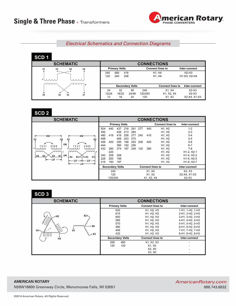
ELECTRICAL SCHEMATICS AND CONNECTION DIAGRAMS
Primary Volts Connect lines to Inter-connect240 480 416 H1, H4 H2-H3120 240 208 H1, H4 H1-H3, H2-H4
SCHEMATIC CONNECTIONSSCD 1
Secondary Volts Connect lines to Inter-connect24 32 48 240 X1, X4 X2-X3
12/24 16/32 24/48 120/240 X1, X2, X4 X2-X312 16 24 120 X1, X2 X2-X4, X1-X3
X2H2
H1
H3
X1X3
X0
123
45
67
Primary Volts Connect lines to Inter-connect 630 H1, H2, H3 1-H1, 1-H2, 1-H3 615 H1, H2, H3 2-H1, 2-H2, 2-H3 600 H1, H2, H3 3-H1, 3-H2, 3-H3 585 H1, H2, H3 4-H1, 4-H2, 4-H3 570 H1, H2, H3 5-H1, 5-H2, 5-H3 480 H1, H2, H3 6-H1, 6-H2, 6-H3 456 H1, H2, H3 7-H1, 7-H2, 7-H3 432 H1, H2, H3 8-H1, 8-H2, 8-H3
SCHEMATIC CONNECTIONSSCD 3
Secondary Volts Connect lines to Inter-connect 208 480 X1, X2, X3 - 120 120 X1, X0 -
X2, X0 -X3, X0 -
HV HVH1 H2 H1 H2
OR
OR
7 8642135 7 8642135
X4 X1X3X2X4 X1X3X2LV LV LV
LV
Primary Volts Connect lines to Inter-connect 504 440 437 218 291 277 440 H1, H2 1-2 492 426 213 284 H1, H2 2-3 480 416 416 208 277 240 416 H1, H2 3-4 468 406 203 270 H1, H2 4-5 456 400 395 198 263 208 400 H1, H2 5-6 444 385 192 256 H1, H2 6-7 432 380 374 187 249 120 380 H1, H2 7-8
220 H1, H2 H1-2, H2-1 240 208 208 H1, H2 H1-4, H2-3 228 200 198 H1, H2 H1-6, H2-5 216 190 187 H1, H2 H1-8, H2-7
SCHEMATIC CONNECTIONSSCD 2
Secondary Volts Connect lines to Inter-connect 240 X1, X4 X2- X3 120 X1, X2 X2-X4, X1-X3 120/240 X1, X2, X4 X2-X3
AmericAn rotAry N59W16600 Greenway Circle, Menomonee Falls, WI 53051
©2014 American Rotary. All Rights Reserved
AmericanRotary.com 888.743.6832
Electrical Schematics and Connection Diagrams
Single & Three Phase » Transformers
277
GEN
ERA
L IN
FOR
MATIO
N
GENERAL INFORMATION
H1 H2
X4 X3X2 X1
H1 H2
X4 X3X2 X1
3 421
H2
H3
H1 X1
X2
X0
X3
123
© Hammond Power Solutions Inc. Data subject to change without notice.
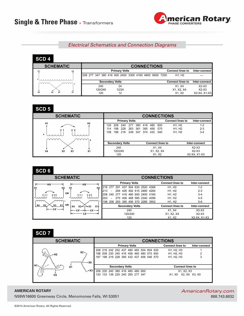
Primary Volts Connect lines to Inter-connect208 277 347 380 416 600 2400 3300 4160 4800 6600 7200 H1, H2 ---
SCHEMATIC CONNECTIONSSCD 4
Secondary Volts Connect lines to Inter-connect240 24 X1, X4 X2-X3
120/240 12/24 X1, X2, X4 X2-X3120 12 X1, X2 X2-X4, X1-X3
ELECTRICAL SCHEMATICS AND CONNECTION DIAGRAMS
Primary Volts Connect lines to Inter-connect 120 208 240 277 380 416 480 600 H1, H2 1-2 114 198 228 263 361 395 456 570 H1, H2 2-3 108 188 216 249 347 374 432 540 H1, H2 3-4
SCHEMATIC CONNECTIONS
Secondary Volts Connect lines to Inter-connect 240 X1, X4 X2-X3 120/240 X1, X2, X4 X2-X3 120 X1, X2 X2-X4, X1-X3
HV HVH1 H2 H1 H2
OR
OR
6 4 2 1 3 5 6 4 2 1 3 5
X4 X1 X3 X2X4 X1 X3 X2LV LV LV
LV
SCHEMATIC CONNECTIONSPrimary Volts Connect lines to Inter-connect
218 277 291 437 504 630 2520 4368 H1, H2 1-2213 - 284 426 492 615 2460 4264 H1, H2 2-3208 240 277 416 480 600 2400 4160 H1, H2 3-4203 - 270 406 468 585 2340 4056 H1, H2 4-5198 208 263 395 456 570 2280 3952 H1, H2 5-6
Secondary Volts Connect lines to Inter-connect240 X1, X4 X2-X3
120/240 X1, X2, X4 X2-X3120 X1, X2 X2-X4, X1-X3
SCD 6
Primary Volts Connect lines to Inter-connect 208 218 242 252 437 480 483 504 604 630 H1, H2, H3 1 198 208 230 240 416 456 460 480 575 600 H1, H2, H3 2 187 198 219 228 395 432 437 456 546 570 H1, H2, H3 3
SCHEMATIC CONNECTIONSSCD 7
Secondary Volts Connect lines to 208 230 240 380 416 460 480 600 X1, X2, X3 120 133 139 220 240 265 277 347 X1, X0 X2, X0 X3, X0
SCD 5
AmericAn rotAry N59W16600 Greenway Circle, Menomonee Falls, WI 53051
©2014 American Rotary. All Rights Reserved
AmericanRotary.com 888.743.6832
Electrical Schematics and Connection Diagrams
Single & Three Phase » Transformers
278
GENERAL INFORMATIONG
ENER
AL
INFO
RM
ATIO
N
H2
H1
H3
X1
X2
X0
X3
12
345
H2
H1 H3
X0X1
X2
X3
64
213
5
© Hammond Power Solutions Inc. Data subject to change without notice.
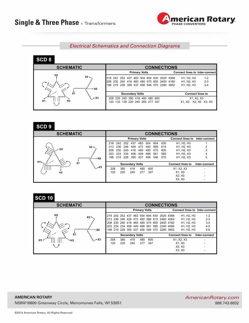
Primary Volts Connect lines to Inter-connect 218 242 252 437 483 504 604 630 H1, H2, H3 1 213 236 246 426 472 492 589 615 H1, H2, H3 2 208 230 240 416 460 480 575 600 H1, H2, H3 3 203 224 234 406 449 468 561 585 H1, H2, H3 4 198 219 228 395 437 456 546 570 H1, H2, H3 5
Secondary Volts Connect lines to Inter-connect 208 380 416 480 600 X1, X2, X3 - 120 220 240 277 347 X1, X0 - X2, X0 - X3, X0 -
SCHEMATIC CONNECTIONSSCD 9
SCHEMATIC CONNECTIONSSCD 10
Secondary Volts Connect lines to Inter-connect 208 380 416 480 600 X1, X2, X3 - 120 220 240 277 347 X1, X0 - X2, X0 - X3, X0 -
Primary Volts Connect lines to Inter-connect
218 242 252 437 483 504 604 630 2520 4368 H1, H2, H3 1-2 213 236 246 426 472 492 589 615 2460 4264 H1, H2, H3 2-3 208 230 240 416 460 480 575 600 2400 4160 H1, H2, H3 3-4 203 224 234 406 449 468 561 585 2340 4056 H1, H2, H3 4-5 198 219 228 395 437 456 546 570 2280 3952 H1, H2, H3 5-6
ELECTRICAL SCHEMATICS AND CONNECTION DIAGRAMS
H2 X2
X0
X3H3H1
X1
42
13
Primary Volts Connect lines to Inter-connect
218 242 252 437 483 504 604 630 2520 4368 H1, H2, H3 1-2 208 230 240 416 460 480 575 600 2400 4160 H1, H2, H3 2-3 198 219 228 395 437 456 546 570 2280 3952 H1, H2, H3 3-4
SCHEMATIC CONNECTIONSSCD 8
Secondary Volts Connect lines to 208 230 240 380 416 460 480 600 X1, X2, X3 120 133 139 220 240 265 277 347 X1, X0 X2, X0 X3, X0
AmericAn rotAry N59W16600 Greenway Circle, Menomonee Falls, WI 53051
©2014 American Rotary. All Rights Reserved
AmericanRotary.com 888.743.6832
Electrical Schematics and Connection Diagrams
Single & Three Phase » Transformers
279
GEN
ERA
L IN
FOR
MATIO
N
GENERAL INFORMATION
H2 X2
H1 H3 X1 X3
12
3
4
X2H2
H1 H3 X1 X3X6
12
3
4
120 120
X2H2
H1
H3
X1X3
X0
1234
56
78910
© Hammond Power Solutions Inc. Data subject to change without notice.
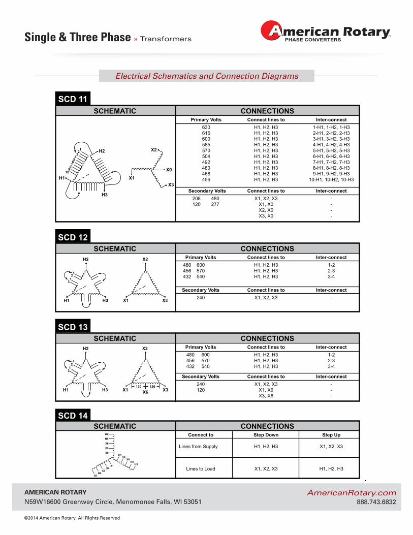
Primary Volts Connect lines to Inter-connect 480 600 H1, H2, H3 1-2 456 570 H1, H2, H3 2-3 432 540 H1, H2, H3 3-4
SCHEMATIC CONNECTIONSSCD 12
Secondary Volts Connect lines to Inter-connect 240 X1, X2, X3 -
Primary Volts Connect lines to Inter-connect 480 600 H1, H2, H3 1-2 456 570 H1, H2, H3 2-3 432 540 H1, H2, H3 3-4
SCHEMATIC CONNECTIONSSCD 13
Secondary Volts Connect lines to Inter-connect 240 X1, X2, X3 - 120 X1, X6 - X3, X6 -
ELECTRICAL SCHEMATICS AND CONNECTION DIAGRAMS
Primary Volts Connect lines to Inter-connect 630 H1, H2, H3 1-H1, 1-H2, 1-H3 615 H1, H2, H3 2-H1, 2-H2, 2-H3 600 H1, H2, H3 3-H1, 3-H2, 3-H3 585 H1, H2, H3 4-H1, 4-H2, 4-H3 570 H1, H2, H3 5-H1, 5-H2, 5-H3 504 H1, H2, H3 6-H1, 6-H2, 6-H3 492 H1, H2, H3 7-H1, 7-H2, 7-H3 480 H1, H2, H3 8-H1, 8-H2, 8-H3 468 H1, H2, H3 9-H1, 9-H2, 9-H3 456 H1, H2, H3 10-H1, 10-H2, 10-H3
SCHEMATIC CONNECTIONSSCD 11
Secondary Volts Connect lines to Inter-connect 208 480 X1, X2, X3 - 120 277 X1, X0 -
X2, X0 -X3, X0 -
X7
H1
H2
H3
X8
X9
H4
X4X1
H6X6
X3
H5
X5
X2
Connect to Step Down Step Up
Lines from Supply H1, H2, H3 X1, X2, X3
Lines to Load X1, X2, X3 H1, H2, H3
SCHEMATIC CONNECTIONSSCD 14
AmericAn rotAry N59W16600 Greenway Circle, Menomonee Falls, WI 53051
©2014 American Rotary. All Rights Reserved
AmericanRotary.com 888.743.6832
Electrical Schematics and Connection Diagrams
Single & Three Phase » Transformers
280
GENERAL INFORMATIONG
ENER
AL
INFO
RM
ATIO
N
H2
H3H1
X1
X2
X3
123
54
HV HVH1 H3 H2 H4 H1 H3 H2 H4
OR
OR
7 8 6 4 2 1 3 5 7 8 6 4 2 1 3 5
X4 X1 X3 X2X4 X1 X3 X2LV LV LV
LV
HV HV
H1 H2H3
H4 H2H3
H4H1
OR
OR X4 X1X3X2X4 X1X3X2
LV LV LV
LV
© Hammond Power Solutions Inc. Data subject to change without notice.
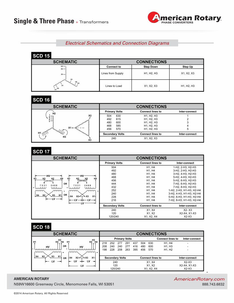
Primary Volts Connect lines to Inter-connect 504 630 H1, H2, H3 1 492 615 H1, H2, H3 2 480 600 H1, H2, H3 3 468 585 H1, H2, H3 4 456 570 H1, H2, H3 5
SCHEMATIC CONNECTIONSSCD 16
Secondary Volts Connect lines to Inter-connect 240 X1, X2, X3
Primary Volts Connect lines to Inter-connect 504 H1, H4 1-H2, 2-H3, H2-H3 492 H1, H4 3-H2, 2-H3, H2-H3 480 H1, H4 3-H2, 4-H3, H2-H3 468 H1, H4 5-H2, 4-H3, H2-H3 456 H1, H4 5-H2, 6-H3, H2-H3 444 H1, H4 7-H2, 6-H3, H2-H3 432 H1, H4 7-H2, 8-H3, H2-H3 252 H1, H4 1-H2, 2-H3, H1-H3, H2-H4 240 H1, H4 3-H2, 4-H3, H1-H3, H2-H4 228 H1, H4 5-H2, 6-H3, H1-H3, H2-H4 216 H1, H4 7-H2, 8-H3, H1-H3, H2-H4
SCHEMATIC CONNECTIONSSCD 17
Secondary Volts Connect lines to Inter-connect 240 X1, X4 X2- X3 120 X1, X2 X2-X4, X1-X3 120/240 X1, X2, X4 X2-X3
Primary Volts Connect lines to Inter-connect 218 252 277 291 437 504 630 H1, H4 - 208 240 240 277 416 480 600 H1, H3 - 198 228 208 263 395 456 570 H1, H2 -
SCHEMATIC CONNECTIONSSCD 18
Secondary Volts Connect lines to Inter-connect 240 X1, X4 X2-X3 120 X1, X2 X2-X4, X1-X3 120/240 X1, X2, X4 X2-X3
ELECTRICAL SCHEMATICS AND CONNECTION DIAGRAMS
H1
H2
H3
H4
X1
H6X3
H5
X2
Connect to Step Down Step Up
Lines from Supply H1, H2, H3 X1, X2, X3
Lines to Load X1, X2, X3 H1, H2, H3
SCHEMATIC CONNECTIONSSCD 15
AmericAn rotAry N59W16600 Greenway Circle, Menomonee Falls, WI 53051
©2014 American Rotary. All Rights Reserved
AmericanRotary.com 888.743.6832
Electrical Schematics and Connection Diagrams
Single & Three Phase » Transformers
281
GEN
ERA
L IN
FOR
MATIO
N
GENERAL INFORMATION
X2H2
H1
H3
X1X3
X0
123
45
67
X2H2
H1 H3
X1X3
X0
86
42
357
1
X2H2
H1
H3X1 X3X6
123
45
67
120V 120V
X2H2
H1 H3 X1 X3X6120V 120V
86
42
357
1
© Hammond Power Solutions Inc. Data subject to change without notice.
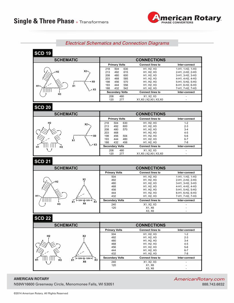
Primary Volts Connect lines to Inter-connect 218 504 630 H1, H2, H3 1-H1, 1-H2, 1-H3 213 492 615 H1, H2, H3 2-H1, 2-H2, 2-H3 208 480 600 H1, H2, H3 3-H1, 3-H2, 3-H3 203 468 585 H1, H2, H3 4-H1, 4-H2, 4-H3 198 456 570 H1, H2, H3 5-H1, 5-H2, 5-H3 193 444 556 H1, H2, H3 6-H1, 6-H2, 6-H3 188 432 542 H1, H2, H3 7-H1, 7-H2, 7-H3
SCHEMATIC CONNECTIONSSCD 19
Secondary Volts Connect lines to Inter-connect 208 480 X1, X2, X3 - 120 277 X1,X0 | X2,X0 | X3,X0 -
Primary Volts Connect lines to Inter-connect 218 504 630 H1, H2, H3 1-2 213 492 600 H1, H2, H3 2-3 208 480 570 H1, H2, H3 3-4 203 468 H1, H2, H3 4-5 198 456 504 H1, H2, H3 5-6 193 444 480 H1, H2, H3 6-7 188 432 456 H1, H2, H3 7-8
SCHEMATIC CONNECTIONSSCD 20
Secondary Volts Connect lines to Inter-connect 208 480 X1, X2, X3 - 120 277 X1,X0 | X2,X0 | X3,X0 -
Primary Volts Connect lines to Inter-connect 504 H1, H2, H3 1-H1, 1-H2, 1-H3 492 H1, H2, H3 2-H1, 2-H2, 2-H3 480 H1, H2, H3 3-H1, 3-H2, 3-H3 468 H1, H2, H3 4-H1, 4-H2, 4-H3 456 H1, H2, H3 5-H1, 5-H2, 5-H3 444 H1, H2, H3 6-H1, 6-H2, 6-H3 432 H1, H2, H3 7-H1, 7-H2, 7-H3
SCHEMATIC CONNECTIONSSCD 21
Secondary Volts Connect lines to Inter-connect 240 X1, X2, X3 - 120 X1, X6 - X3, X6 -
ELECTRICAL SCHEMATICS AND CONNECTION DIAGRAMS
Primary Volts Connect lines to Inter-connect 504 H1, H2, H3 1-2 492 H1, H2, H3 2-3 480 H1, H2, H3 3-4 468 H1, H2, H3 4-5 456 H1, H2, H3 5-6 444 H1, H2, H3 6-7 432 H1, H2, H3 7-8
SCHEMATIC CONNECTIONSSCD 22
Secondary Volts Connect lines to Inter-connect 240 X1, X2, X3 - 120 X1, X6 - X3, X6 -
AmericAn rotAry N59W16600 Greenway Circle, Menomonee Falls, WI 53051
©2014 American Rotary. All Rights Reserved
AmericanRotary.com 888.743.6832
Electrical Schematics and Connection Diagrams
Single & Three Phase » Transformers
282
GENERAL INFORMATIONG
ENER
AL
INFO
RM
ATIO
N
H2
H3
H1
X1
X2
X3
1423
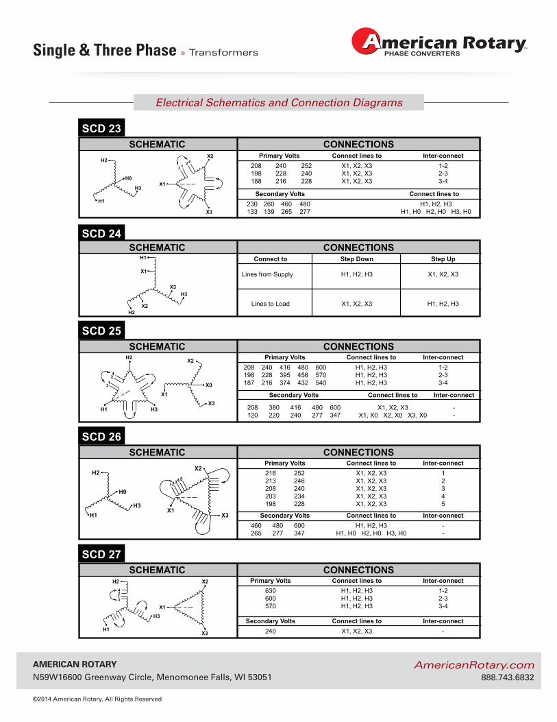
Primary Volts Connect lines to Inter-connect 630 H1, H2, H3 1-2 600 H1, H2, H3 2-3 570 H1, H2, H3 3-4
SCHEMATIC CONNECTIONSSCD 27
Secondary Volts Connect lines to Inter-connect 240 X1, X2, X3 -
H2X2
H1
H3X1
X3
12
34
H0
X2H2
H1
H3
X1
X3
H2 X2
X0
X3H3H1
X1
42
13
H2X2
H1H3
X1X3
123
H0
54
SCHEMATIC CONNECTIONSSCD 26
Secondary Volts Connect lines to Inter-connect 460 480 600 H1, H2, H3 - 265 277 347 H1, H0 H2, H0 H3, H0 -
Primary Volts Connect lines to Inter-connect 218 252 X1, X2, X3 1 213 246 X1, X2, X3 2 208 240 X1, X2, X3 3 203 234 X1, X2, X3 4 198 228 X1, X2, X3 5
SCHEMATIC CONNECTIONSSCD 25
Primary Volts Connect lines to Inter-connect 208 240 416 480 600 H1, H2, H3 1-2 198 228 395 456 570 H1, H2, H3 2-3 187 216 374 432 540 H1, H2, H3 3-4
Secondary Volts Connect lines to Inter-connect
208 380 416 480 600 X1, X2, X3 - 120 220 240 277 347 X1, X0 X2, X0 X3, X0 -
© Hammond Power Solutions Inc. Data subject to change without notice.
ELECTRICAL SCHEMATICS AND CONNECTION DIAGRAMS
Primary Volts Connect lines to Inter-connect 208 240 252 X1, X2, X3 1-2
198 228 240 X1, X2, X3 2-3188 216 228 X1, X2, X3 3-4
SCHEMATIC CONNECTIONSSCD 23
Secondary Volts Connect lines to 230 260 460 480 H1, H2, H3 133 139 265 277 H1, H0 H2, H0 H3, H0
Connect to Step Down Step Up
Lines from Supply H1, H2, H3 X1, X2, X3
Lines to Load X1, X2, X3 H1, H2, H3
SCHEMATIC CONNECTIONSSCD 24
AmericAn rotAry N59W16600 Greenway Circle, Menomonee Falls, WI 53051
©2014 American Rotary. All Rights Reserved
AmericanRotary.com 888.743.6832
Electrical Schematics and Connection Diagrams
Single & Three Phase » Transformers
283
GEN
ERA
L IN
FOR
MATIO
N
GENERAL INFORMATION
H2
H3
H1
X1
X2
X3
1
64235
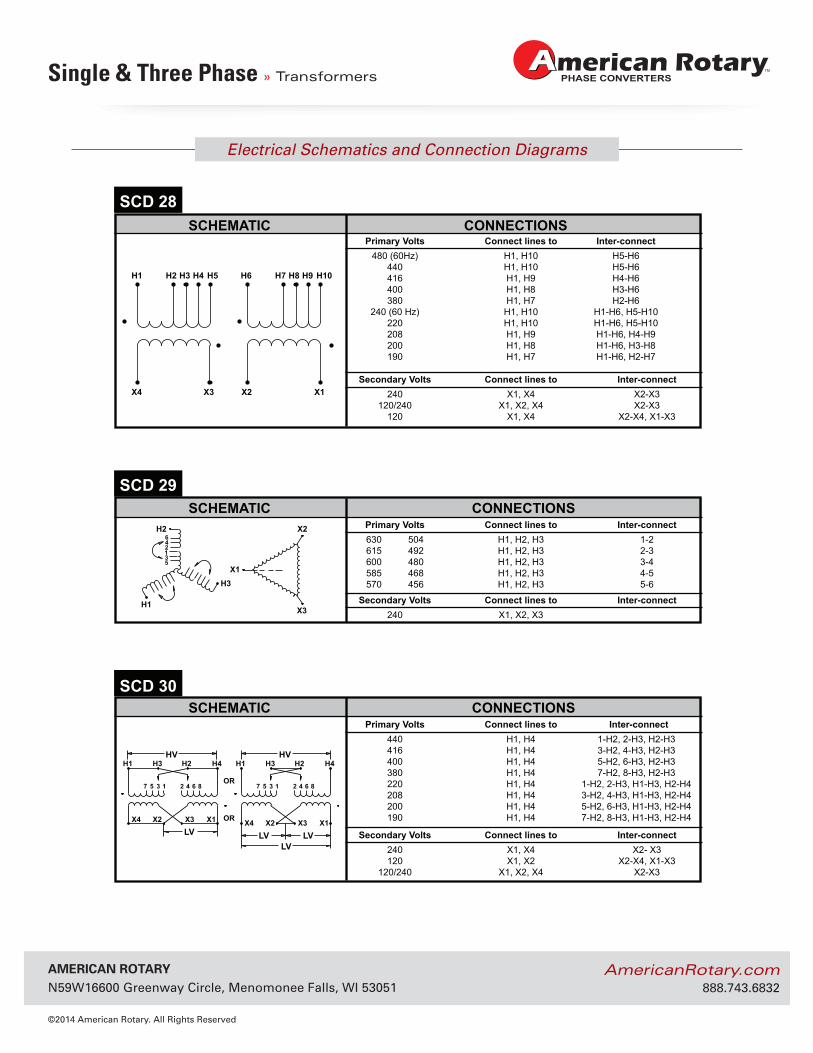
Primary Volts Connect lines to Inter-connect 630 504 H1, H2, H3 1-2 615 492 H1, H2, H3 2-3 600 480 H1, H2, H3 3-4 585 468 H1, H2, H3 4-5 570 456 H1, H2, H3 5-6
SCHEMATIC CONNECTIONSSCD 29
Secondary Volts Connect lines to Inter-connect 240 X1, X2, X3
H1
X4 X3 X2 X1
H2 H3 H4 H5 H6 H7 H8 H9 H10
Primary Volts Connect lines to Inter-connect 480 (60Hz) H1, H10 H5-H6 440 H1, H10 H5-H6 416 H1, H9 H4-H6 400 H1, H8 H3-H6 380 H1, H7 H2-H6 240 (60 Hz) H1, H10 H1-H6, H5-H10 220 H1, H10 H1-H6, H5-H10 208 H1, H9 H1-H6, H4-H9 200 H1, H8 H1-H6, H3-H8 190 H1, H7 H1-H6, H2-H7
SCHEMATIC CONNECTIONSSCD 28
Secondary Volts Connect lines to Inter-connect 240 X1, X4 X2-X3 120/240 X1, X2, X4 X2-X3 120 X1, X4 X2-X4, X1-X3
HV HVH1 H3 H2 H4 H1 H3 H2 H4
OR
OR
7 8 6 4 2 1 3 5 7 8 6 4 2 1 3 5
X4 X1 X3 X2X4 X1 X3 X2LV LV LV
LV
Primary Volts Connect lines to Inter-connect 440 H1, H4 1-H2, 2-H3, H2-H3 416 H1, H4 3-H2, 4-H3, H2-H3 400 H1, H4 5-H2, 6-H3, H2-H3 380 H1, H4 7-H2, 8-H3, H2-H3 220 H1, H4 1-H2, 2-H3, H1-H3, H2-H4 208 H1, H4 3-H2, 4-H3, H1-H3, H2-H4 200 H1, H4 5-H2, 6-H3, H1-H3, H2-H4 190 H1, H4 7-H2, 8-H3, H1-H3, H2-H4
SCHEMATIC CONNECTIONSSCD 30
Secondary Volts Connect lines to Inter-connect 240 X1, X4 X2- X3 120 X1, X2 X2-X4, X1-X3 120/240 X1, X2, X4 X2-X3
© Hammond Power Solutions Inc. Data subject to change without notice.
ELECTRICAL SCHEMATICS AND CONNECTION DIAGRAMS
AmericAn rotAry N59W16600 Greenway Circle, Menomonee Falls, WI 53051
©2014 American Rotary. All Rights Reserved
AmericanRotary.com 888.743.6832
Electrical Schematics and Connection Diagrams
Single & Three Phase » Transformers
284
GENERAL INFORMATIONG
ENER
AL
INFO
RM
ATIO
N
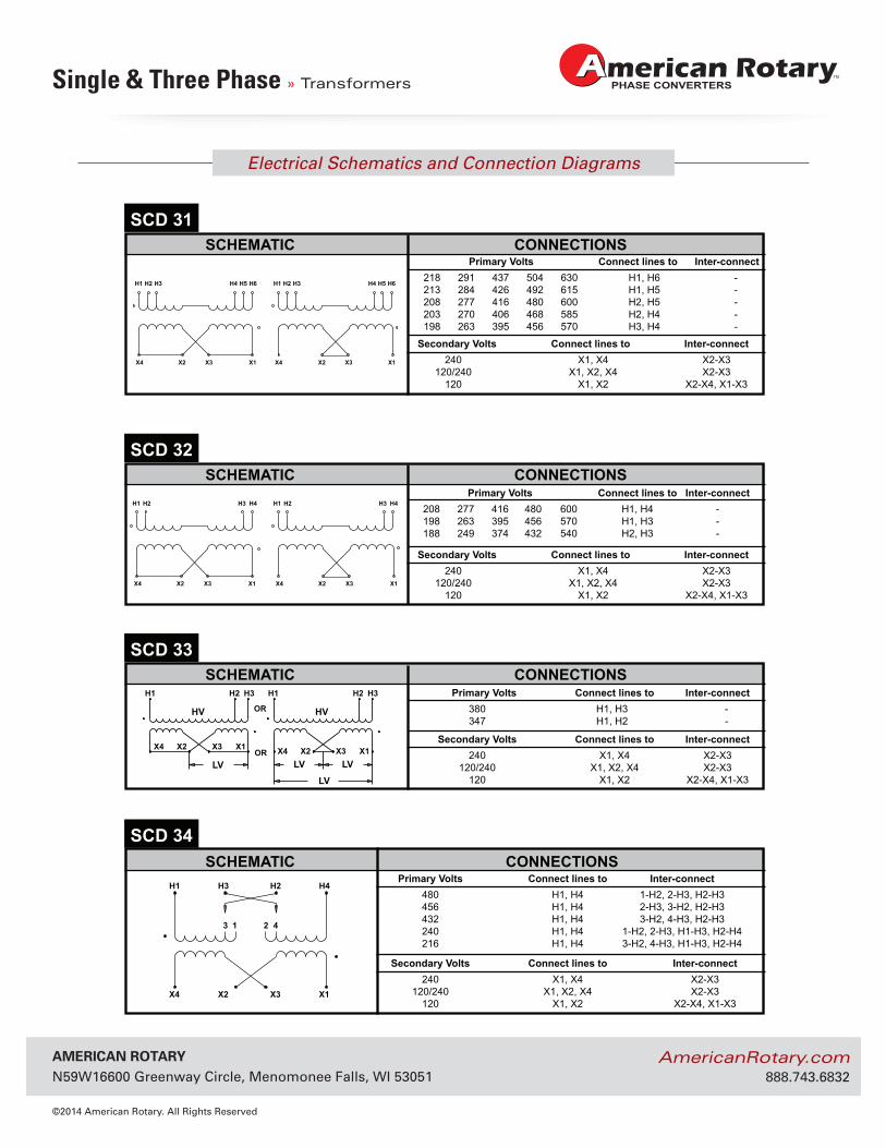
Primary Volts Connect lines to Inter-connect218 291 437 504 630 H1, H6 -213 284 426 492 615 H1, H5 -208 277 416 480 600 H2, H5 -203 270 406 468 585 H2, H4 -198 263 395 456 570 H3, H4 -
SCHEMATIC CONNECTIONSSCD 31
Secondary Volts Connect lines to Inter-connect240 X1, X4 X2-X3
120/240 X1, X2, X4 X2-X3120 X1, X2 X2-X4, X1-X3
X4 X2 X3 X1
H1 H2 H3 H4 H5 H6
X4 X2 X3 X1
H1 H2 H3 H4 H5 H6
Primary Volts Connect lines to Inter-connect 480 H1, H4 1-H2, 2-H3, H2-H3 456 H1, H4 2-H3, 3-H2, H2-H3 432 H1, H4 3-H2, 4-H3, H2-H3 240 H1, H4 1-H2, 2-H3, H1-H3, H2-H4 216 H1, H4 3-H2, 4-H3, H1-H3, H2-H4
SCHEMATIC CONNECTIONSSCD 34
Secondary Volts Connect lines to Inter-connect 240 X1, X4 X2-X3 120/240 X1, X2, X4 X2-X3 120 X1, X2 X2-X4, X1-X3
H1 H4H2H3
X4 X1X3X2
4213
Primary Volts Connect lines to Inter-connect208 277 416 480 600 H1, H4 -198 263 395 456 570 H1, H3 -188 249 374 432 540 H2, H3 -
SCHEMATIC CONNECTIONSSCD 32
Secondary Volts Connect lines to Inter-connect240 X1, X4 X2-X3
120/240 X1, X2, X4 X2-X3120 X1, X2 X2-X4, X1-X3
X4 X2 X3 X1
H1 H2 H3 H4 H1 H2 H3 H4
X4 X2 X3 X1
© Hammond Power Solutions Inc. Data subject to change without notice.
ELECTRICAL SCHEMATICS AND CONNECTION DIAGRAMS
Primary Volts Connect lines to Inter-connect380 H1, H3 -347 H1, H2 -
SCHEMATIC CONNECTIONSSCD 33
Secondary Volts Connect lines to Inter-connect240 X1, X4 X2-X3
120/240 X1, X2, X4 X2-X3120 X1, X2 X2-X4, X1-X3
HV HV
H1 H2 H3 H2 H3H1
OR
OR X4 X1X3X2X4 X1X3X2
LV LV LV
LV
AmericAn rotAry N59W16600 Greenway Circle, Menomonee Falls, WI 53051
©2014 American Rotary. All Rights Reserved
AmericanRotary.com 888.743.6832
Electrical Schematics and Connection Diagrams
Single & Three Phase » Transformers
285
GEN
ERA
L IN
FOR
MATIO
N
GENERAL INFORMATION
SCHEMATIC CONNECTIONSSCD 36
H3
H2
H1
41
32
6
X0,Y0
Y3
Y2
Y1
X3
X2
X1
5
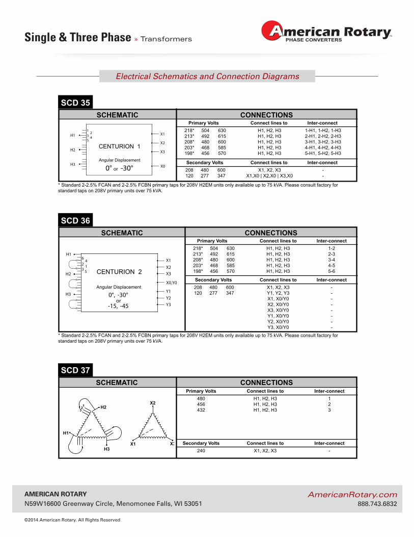
Angular Displacement
0°, -30°or
-15, -45
CENTURION 2
Primary Volts Connect lines to Inter-connect 218* 504 630 H1, H2, H3 1-2 213* 492 615 H1, H2, H3 2-3 208* 480 600 H1, H2, H3 3-4 203* 468 585 H1, H2, H3 4-5 198* 456 570 H1, H2, H3 5-6
Secondary Volts Connect lines to Inter-connect208 480 600 X1, X2, X3 -120 277 347 Y1, Y2, Y3 -
X1, X0/Y0 - X2, X0/Y0 - X3, X0/Y0 - Y1, X0/Y0 - Y2, X0/Y0 - Y3, X0/Y0 -
* Standard 2-2.5% FCAN and 2-2.5% FCBN primary taps for 208V H2EM units only available up to 75 kVA. Please consult factory for standard taps on 208V primary units over 75 kVA.
X2H2
H1
H3X1 X3
123
Primary Volts Connect lines to Inter-connect 218* 504 630 H1, H2, H3 1-H1, 1-H2, 1-H3
213* 492 615 H1, H2, H3 2-H1, 2-H2, 2-H3208* 480 600 H1, H2, H3 3-H1, 3-H2, 3-H3203* 468 585 H1, H2, H3 4-H1, 4-H2, 4-H3198* 456 570 H1, H2, H3 5-H1, 5-H2, 5-H3
SCHEMATIC CONNECTIONSSCD 35
Secondary Volts Connect lines to Inter-connect208 480 600 X1, X2, X3 -120 277 347 X1,X0 | X2,X0 | X3,X0 -
Angular Displacement
0° or -30°
CENTURION 1
H1 3 4
12
5
H2
H3
X1
X2
X3
X0
* Standard 2-2.5% FCAN and 2-2.5% FCBN primary taps for 208V H2EM units only available up to 75 kVA. Please consult factory for standard taps on 208V primary units over 75 kVA.
© Hammond Power Solutions Inc. Data subject to change without notice.
ELECTRICAL SCHEMATICS AND CONNECTION DIAGRAMS
Primary Volts Connect lines to Inter-connect 480 H1, H2, H3 1 456 H1, H2, H3 2 432 H1, H2, H3 3
SCHEMATIC CONNECTIONSSCD 37
Secondary Volts Connect lines to Inter-connect 240 X1, X2, X3 -
AmericAn rotAry N59W16600 Greenway Circle, Menomonee Falls, WI 53051
©2014 American Rotary. All Rights Reserved
AmericanRotary.com 888.743.6832
Electrical Schematics and Connection Diagrams
Single & Three Phase » Transformers
286
GENERAL INFORMATIONG
ENER
AL
INFO
RM
ATIO
N
X2H2
X1 X3
H1
123
45
67
H3
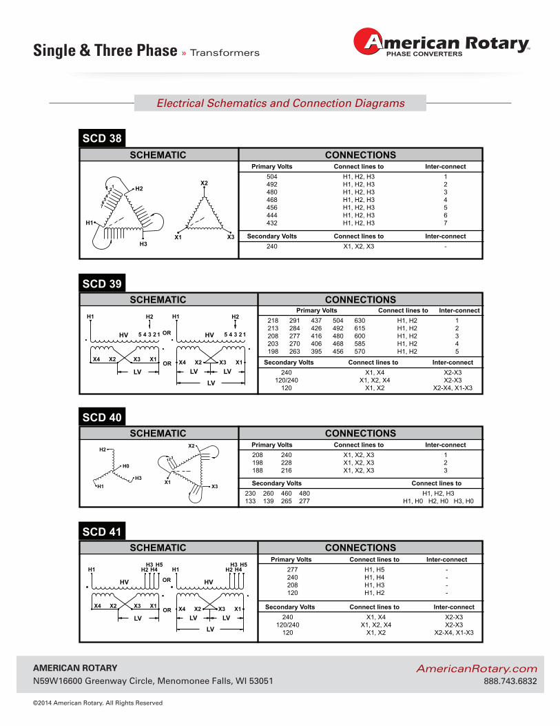
Primary Volts Connect lines to Inter-connect218 291 437 504 630 H1, H2 1213 284 426 492 615 H1, H2 2208 277 416 480 600 H1, H2 3203 270 406 468 585 H1, H2 4198 263 395 456 570 H1, H2 5
Primary Volts Connect lines to Inter-connect277 H1, H5 -240 H1, H4 -208 H1, H3 -120 H1, H2 -
SCHEMATIC CONNECTIONSSCD 39
Secondary Volts Connect lines to Inter-connect240 X1, X4 X2-X3
120/240 X1, X2, X4 X2-X3120 X1, X2 X2-X4, X1-X3
Secondary Volts Connect lines to Inter-connect240 X1, X4 X2-X3
120/240 X1, X2, X4 X2-X3120 X1, X2 X2-X4, X1-X3
HV HV
H1 H2
12345
H1
OR
OR X4 X1 X3 X2X4 X1 X3 X2
LV LV LV
LV
H2
12345
H2X2
H1H3
X1X3
123
H0
Primary Volts Connect lines to Inter-connect 208 240 X1, X2, X3 1 198 228 X1, X2, X3 2 188 216 X1, X2, X3 3
SCHEMATIC CONNECTIONSSCD 40
Secondary Volts Connect lines to 230 260 460 480 H1, H2, H3 133 139 265 277 H1, H0 H2, H0 H3, H0
HV HV
H1 H4H2H5H3
H4H2H5H3
H1
OR
OR X4 X1 X3 X2X4 X1 X3 X2
LV LV LV
LV
SCHEMATIC CONNECTIONSSCD 41
© Hammond Power Solutions Inc. Data subject to change without notice.
Primary Volts Connect lines to Inter-connect 504 H1, H2, H3 1 492 H1, H2, H3 2 480 H1, H2, H3 3 468 H1, H2, H3 4 456 H1, H2, H3 5 444 H1, H2, H3 6 432 H1, H2, H3 7
SCHEMATIC CONNECTIONSSCD 38
Secondary Volts Connect lines to Inter-connect 240 X1, X2, X3 -
ELECTRICAL SCHEMATICS AND CONNECTION DIAGRAMS
AmericAn rotAry N59W16600 Greenway Circle, Menomonee Falls, WI 53051
©2014 American Rotary. All Rights Reserved
AmericanRotary.com 888.743.6832
Electrical Schematics and Connection Diagrams
Single & Three Phase » Transformers
287
GEN
ERA
L IN
FOR
MATIO
N
GENERAL INFORMATION
H1 H2
X2 X1
3 4 2 1
X4 X6 X5 X3
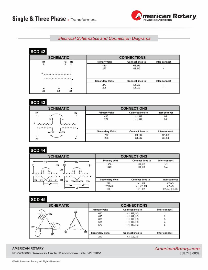
SCHEMATIC CONNECTIONSSCD 43
HV HVH1 H2 H1 H2
OR
OR
4 2 1 3 4 2 1 3
X4 X1 X3 X2X4 X1 X3 X2LV LV LV
LV
SCHEMATIC CONNECTIONSSCD 44
X2H2
H1
H3X1 X3
123
45
SCHEMATIC CONNECTIONSSCD 45
Primary Volts Connect lines to Inter-connect380 H1, H2 1-2347 H1, H2 3-4
Secondary Volts Connect lines to Inter-connect240 X1, X4 X2-X3
120/240 X1, X2, X4 X2-X3120 X1, X2 X2-X4, X1-X3
H1
X3 X1
H2 H3
X2
SCHEMATIC CONNECTIONSSCD 42
© Hammond Power Solutions Inc. Data subject to change without notice.
Primary Volts Connect lines to Inter-connect480 H1, H2 1-2277 H1, H2 3-4
Secondary Volts Connect lines to Inter-connect277 X1, X2 X5-X6208 X1, X2 X3-X4
Primary Volts Connect lines to Inter-connect 630 H1, H2, H3 1 615 H1, H2, H3 2 600 H1, H2, H3 3 585 H1, H2, H3 4 570 H1, H2, H3 5
Secondary Volts Connect lines to Inter-connect 240 X1, X2, X3 -
ELECTRICAL SCHEMATICS AND CONNECTION DIAGRAMS
Primary Volts Connect lines to Inter-connect480 H1, H3 -277 H1, H2 -
Secondary Volts Connect lines to Inter-connect277 X1, X3 -208 X1, X2 -
AmericAn rotAry N59W16600 Greenway Circle, Menomonee Falls, WI 53051
©2014 American Rotary. All Rights Reserved
AmericanRotary.com 888.743.6832
Electrical Schematics and Connection Diagrams
Single & Three Phase » Transformers
288
GENERAL INFORMATIONG
ENER
AL
INFO
RM
ATIO
N
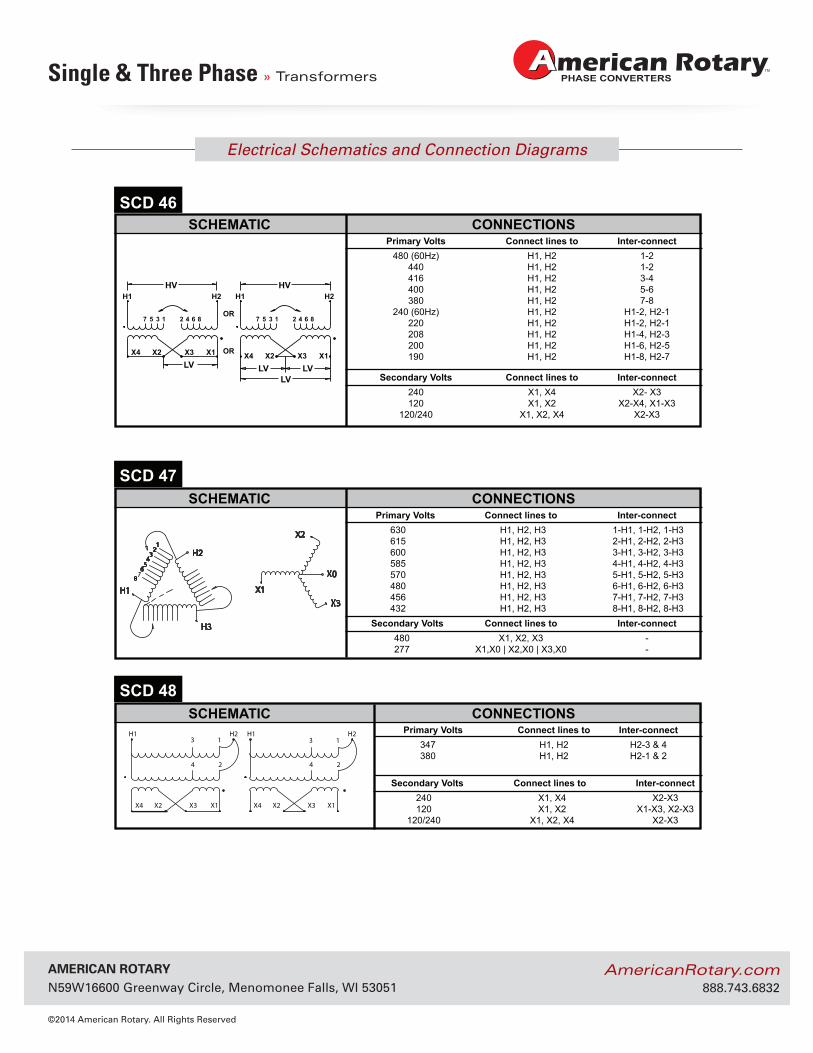
SCHEMATIC CONNECTIONSSCD 48
Primary Volts Connect lines to Inter-connect347 H1, H2 H2-3 & 4380 H1, H2 H2-1 & 2
Secondary Volts Connect lines to Inter-connect240 X1, X4 X2-X3120 X1, X2 X1-X3, X2-X3
120/240 X1, X2, X4 X2-X3
H1 H2
X4 X2 X3 X1 X1X3X2X4
13
24 4 2
3 1H2H1
© Hammond Power Solutions Inc. Data subject to change without notice.
ELECTRICAL SCHEMATICS AND CONNECTION DIAGRAMS
HV HVH1 H2 H1 H2
OR
OR
7 8642135 7 8642135
X4 X1X3X2X4 X1X3X2LV LV LV
LV
Primary Volts Connect lines to Inter-connect480 (60Hz) H1, H2 1-2
440 H1, H2 1-2416 H1, H2 3-4400 H1, H2 5-6380 H1, H2 7-8
240 (60Hz) H1, H2 H1-2, H2-1220 H1, H2 H1-2, H2-1208 H1, H2 H1-4, H2-3200 H1, H2 H1-6, H2-5190 H1, H2 H1-8, H2-7
SCHEMATIC CONNECTIONSSCD 46
Secondary Volts Connect lines to Inter-connect240 X1, X4 X2- X3120 X1, X2 X2-X4, X1-X3
120/240 X1, X2, X4 X2-X3
Primary Volts Connect lines to Inter-connect630 H1, H2, H3 1-H1, 1-H2, 1-H3615 H1, H2, H3 2-H1, 2-H2, 2-H3600 H1, H2, H3 3-H1, 3-H2, 3-H3585 H1, H2, H3 4-H1, 4-H2, 4-H3570 H1, H2, H3 5-H1, 5-H2, 5-H3480 H1, H2, H3 6-H1, 6-H2, 6-H3456 H1, H2, H3 7-H1, 7-H2, 7-H3432 H1, H2, H3 8-H1, 8-H2, 8-H3
SCHEMATIC CONNECTIONSSCD 47
Secondary Volts Connect lines to Inter-connect 480 X1, X2, X3 - 277 X1,X0 | X2,X0 | X3,X0 -
6
12
34
5
H1
H3
H2
8
X3X1
X2
X0
AmericAn rotAry N59W16600 Greenway Circle, Menomonee Falls, WI 53051
©2014 American Rotary. All Rights Reserved
AmericanRotary.com 888.743.6832
Electrical Schematics and Connection Diagrams
Single & Three Phase » Transformers
289
GEN
ERA
L IN
FOR
MATIO
N
GENERAL INFORMATION
© Hammond Power Solutions Inc. Data subject to change without notice.
ELECTRICAL SCHEMATICS AND CONNECTION DIAGRAMS
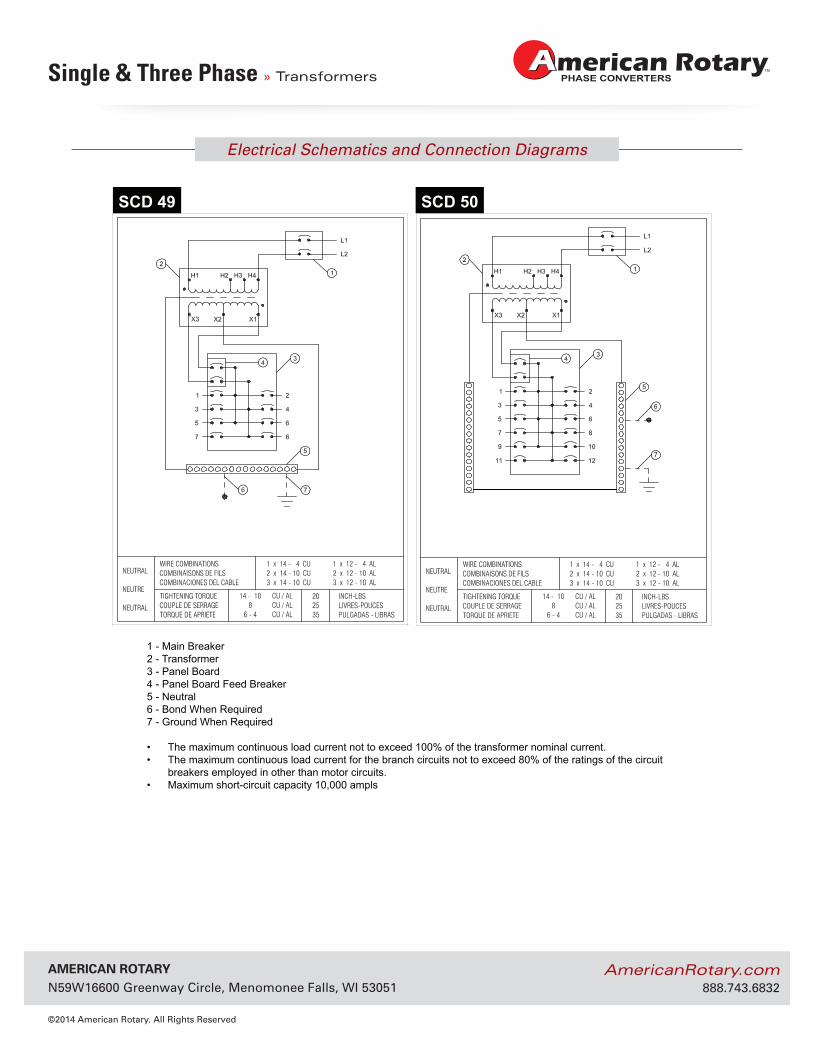
1 - Main Breaker2 - Transformer3 - Panel Board4 - Panel Board Feed Breaker5 - Neutral6 - Bond When Required7 - Ground When Required
• The maximum continuous load current not to exceed 100% of the transformer nominal current.• The maximum continuous load current for the branch circuits not to exceed 80% of the ratings of the circuit
breakers employed in other than motor circuits.• Maximum short-circuit capacity 10,000 ampls
SCD 49 SCD 50
AmericAn rotAry N59W16600 Greenway Circle, Menomonee Falls, WI 53051
©2014 American Rotary. All Rights Reserved
AmericanRotary.com 888.743.6832
Electrical Schematics and Connection Diagrams
Single & Three Phase » Transformers
290
GENERAL INFORMATIONG
ENER
AL
INFO
RM
ATIO
N
© Hammond Power Solutions Inc. Data subject to change without notice.
ELECTRICAL SCHEMATICS AND CONNECTION DIAGRAMS
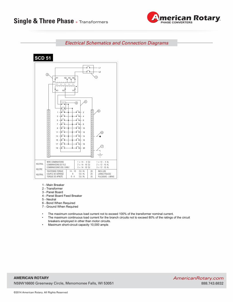
1 - Main Breaker2 - Transformer3 - Panel Board4 - Panel Board Feed Breaker5 - Neutral6 - Bond When Required7 - Ground When Required
• The maximum continuous load current not to exceed 100% of the transformer nominal current.• The maximum continuous load current for the branch circuits not to exceed 80% of the ratings of the circuit
breakers employed in other than motor circuits.• Maximum short-circuit capacity 10,000 ampls
SCD 51
AmericAn rotAry N59W16600 Greenway Circle, Menomonee Falls, WI 53051
©2014 American Rotary. All Rights Reserved
AmericanRotary.com 888.743.6832
Electrical Schematics and Connection Diagrams
Single & Three Phase » Transformers
260
GENERAL INFORMATION
GEN
ERA
L IN
FOR
MAT
ION
CaseStyle
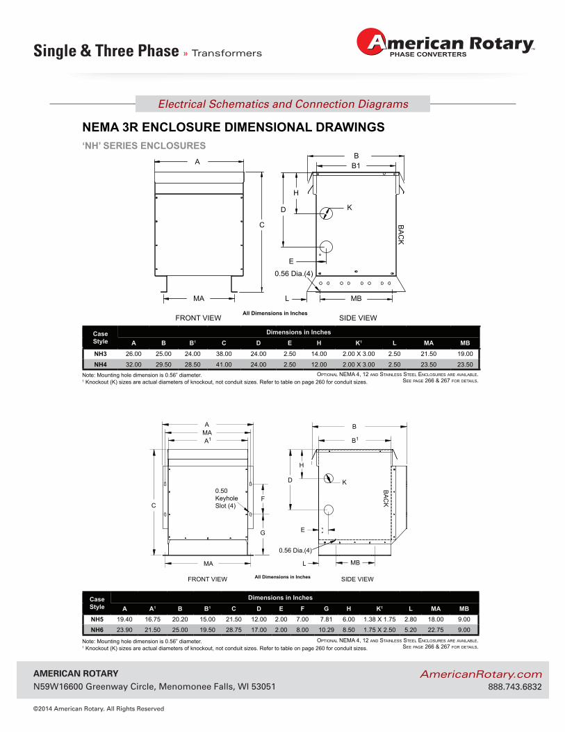
Dimensions in InchesA B B1 C D E H K1 L MA MB
NH3 26.00 25.00 24.00 38.00 24.00 2.50 14.00 2.00 X 3.00 2.50 21.50 19.00
NH4 32.00 29.50 28.50 41.00 24.00 2.50 12.00 2.00 X 3.00 2.50 23.50 23.50
CaseStyle
Dimensions in Inches
A A1 B B1 C D E F G H K1 L MA MBNH5 19.40 16.75 20.20 15.00 21.50 12.00 2.00 7.00 7.81 6.00 1.38 X 1.75 2.80 18.00 9.00
NH6 23.90 21.50 25.00 19.50 28.75 17.00 2.00 8.00 10.29 8.50 1.75 X 2.50 5.20 22.75 9.00
Note: Mounting hole dimension is 0.56” diameter.
Note: Mounting hole dimension is 0.56” diameter.
© Hammond Power Solutions Inc. Data subject to change without notice.
‘NH’ SERIES ENCLOSURES
NEMA 3R ENCLOSURE DIMENSIONAL DRAWINGS
FRONT VIEW SIDE VIEW
F
BMAA
A1
MA
B1
D
H
MB
E
C
K
L
0.56 Dia.(4)
0.50KeyholeSlot (4)
BA
CK
All Dimensions in Inches
G
MA
FRONT VIEW SIDE VIEW
A
C
D
H
K
B1
MBL
E
0.56 Dia.(4)
BB
AC
K
All Dimensions in Inches
OptiOnal nEMa 4, 12 and StainlESS StEEl EnclOSurES arE availablE.SEE pagE 266 & 267 fOr dEtailS.
OptiOnal nEMa 4, 12 and StainlESS StEEl EnclOSurES arE availablE.SEE pagE 266 & 267 fOr dEtailS.
1 Knockout (K) sizes are actual diameters of knockout, not conduit sizes. Refer to table on page 260 for conduit sizes.
1 Knockout (K) sizes are actual diameters of knockout, not conduit sizes. Refer to table on page 260 for conduit sizes.
AmericAn rotAry N59W16600 Greenway Circle, Menomonee Falls, WI 53051
©2014 American Rotary. All Rights Reserved
AmericanRotary.com 888.743.6832
Electrical Schematics and Connection Diagrams
Single & Three Phase » Transformers
261
GEN
ERA
L IN
FOR
MATIO
N
GENERAL INFORMATION
CaseStyle
Dimensions in Inches
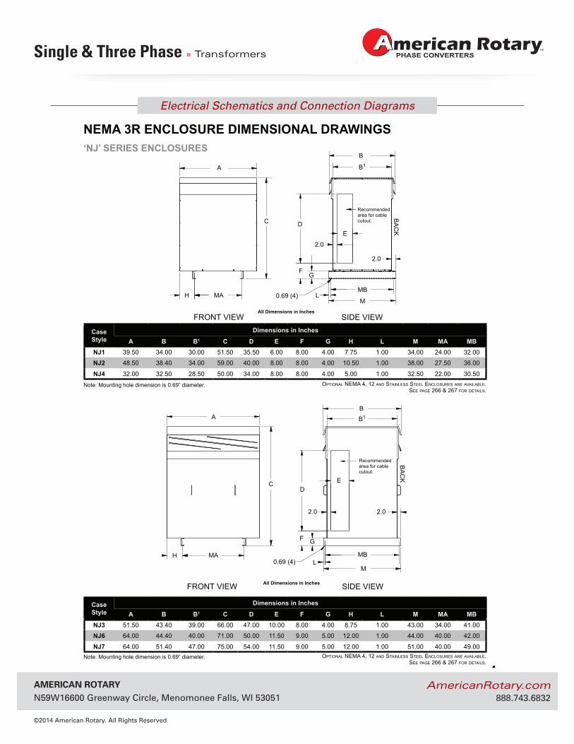
A B B1 C D E F G H L M MA MBNJ1 39.50 34.00 30.00 51.50 35.50 6.00 8.00 4.00 7.75 1.00 34.00 24.00 32.00
NJ2 48.50 38.40 34.00 59.00 40.00 8.00 8.00 4.00 10.50 1.00 38.00 27.50 36.00
NJ4 32.00 32.50 28.50 50.00 34.00 8.00 8.00 4.00 5.00 1.00 32.50 22.00 30.50
CaseStyle
Dimensions in Inches
A B B1 C D E F G H L M MA MBNJ3 51.50 43.40 39.00 66.00 47.00 10.00 8.00 4.00 8.75 1.00 43.00 34.00 41.00
NJ6 64.00 44.40 40.00 71.00 50.00 11.50 9.00 5.00 12.00 1.00 44.00 40.00 42.00
NJ7 64.00 51.40 47.00 75.00 54.00 11.50 9.00 5.00 12.00 1.00 51.00 40.00 49.00
Note: Mounting hole dimension is 0.69” diameter.
© Hammond Power Solutions Inc. Data subject to change without notice.
‘NJ’ SERIES ENCLOSURES
NEMA 3R ENCLOSURE DIMENSIONAL DRAWINGS
FRONT VIEW SIDE VIEW All Dimensions in Inches
H MA 0.69 (4)
A
M
MBL
FG
2.0
E
2.0
C D
B1
B
Recommendedarea for cable cutout.
BA
CK
FRONT VIEW SIDE VIEW All Dimensions in Inches
BA
CK
Recommendedarea for cable cutout.
H MA0.69 (4)
A
M
MBL
F G
2.0
E
2.0
DC
B1
B
Note: Mounting hole dimension is 0.69” diameter.
OptiOnal nEMa 4, 12 and StainlESS StEEl EnclOSurES arE availablE.SEE pagE 266 & 267 fOr dEtailS.
OptiOnal nEMa 4, 12 and StainlESS StEEl EnclOSurES arE availablE.SEE pagE 266 & 267 fOr dEtailS.
AmericAn rotAry N59W16600 Greenway Circle, Menomonee Falls, WI 53051
©2014 American Rotary. All Rights Reserved
AmericanRotary.com 888.743.6832
Electrical Schematics and Connection Diagrams
Single & Three Phase » Transformers
262
GENERAL INFORMATION
GEN
ERA
L IN
FOR
MAT
ION
CaseStyle Fig #
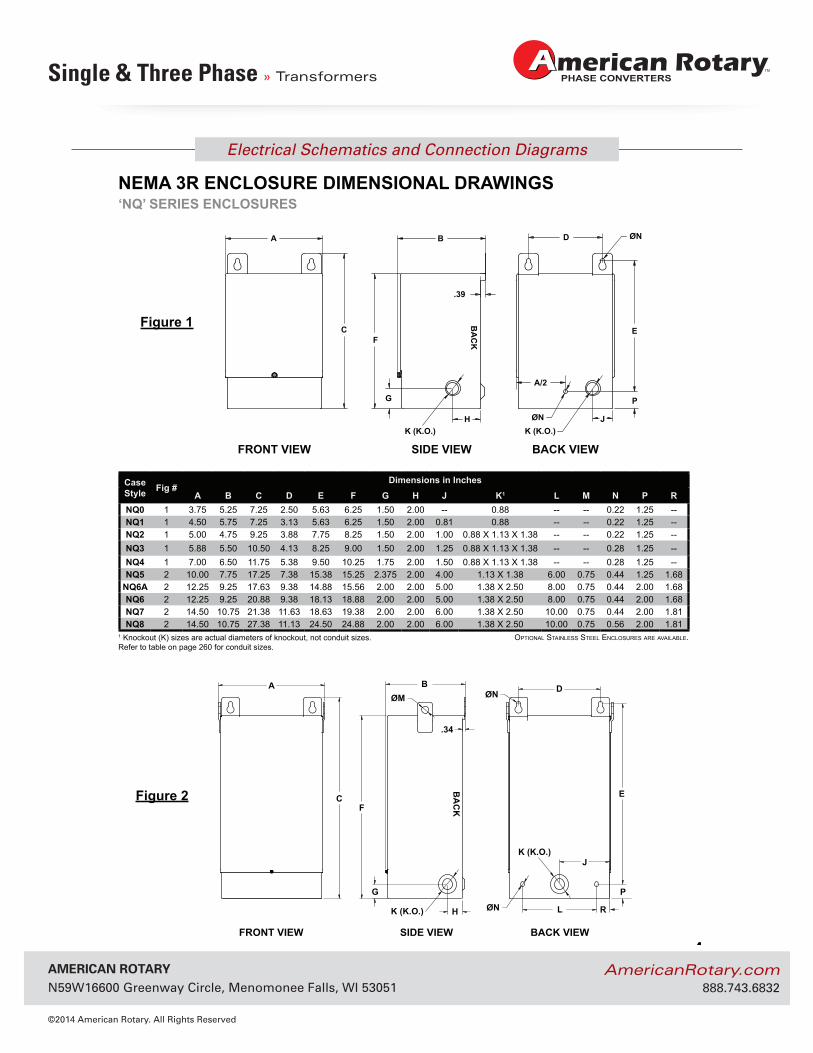
Dimensions in InchesA B C D E F G H J K1 L M N P R
NQ0 1 3.75 5.25 7.25 2.50 5.63 6.25 1.50 2.00 -- 0.88 -- -- 0.22 1.25 --NQ1 1 4.50 5.75 7.25 3.13 5.63 6.25 1.50 2.00 0.81 0.88 -- -- 0.22 1.25 --NQ2 1 5.00 4.75 9.25 3.88 7.75 8.25 1.50 2.00 1.00 0.88 X 1.13 X 1.38 -- -- 0.22 1.25 --NQ3 1 5.88 5.50 10.50 4.13 8.25 9.00 1.50 2.00 1.25 0.88 X 1.13 X 1.38 -- -- 0.28 1.25 --NQ4 1 7.00 6.50 11.75 5.38 9.50 10.25 1.75 2.00 1.50 0.88 X 1.13 X 1.38 -- -- 0.28 1.25 --NQ5 2 10.00 7.75 17.25 7.38 15.38 15.25 2.375 2.00 4.00 1.13 X 1.38 6.00 0.75 0.44 1.25 1.68
NQ6A 2 12.25 9.25 17.63 9.38 14.88 15.56 2.00 2.00 5.00 1.38 X 2.50 8.00 0.75 0.44 2.00 1.68NQ6 2 12.25 9.25 20.88 9.38 18.13 18.88 2.00 2.00 5.00 1.38 X 2.50 8.00 0.75 0.44 2.00 1.68NQ7 2 14.50 10.75 21.38 11.63 18.63 19.38 2.00 2.00 6.00 1.38 X 2.50 10.00 0.75 0.44 2.00 1.81NQ8 2 14.50 10.75 27.38 11.13 24.50 24.88 2.00 2.00 6.00 1.38 X 2.50 10.00 0.75 0.56 2.00 1.81
© Hammond Power Solutions Inc. Data subject to change without notice.
‘NQ’ SERIES ENCLOSURESNEMA 3R ENCLOSURE DIMENSIONAL DRAWINGS
OptiOnal StainlESS StEEl EnclOSurES arE availablE.1 Knockout (K) sizes are actual diameters of knockout, not conduit sizes. Refer to table on page 260 for conduit sizes.
A
C
G
F
BØM
H
.34
LØN
ØN D
J
E
K (K.O.)
K (K.O.)
P
R
FRONT VIEW SIDE VIEW BACK VIEW
BA
CK
Figure 2
A
C
B
F
G
K (K.O.)
.39
H
D
E
J
ØN
ØNK (K.O.)
P
A/2
FRONT VIEW SIDE VIEW BACK VIEW
BA
CK
Figure 1
AmericAn rotAry N59W16600 Greenway Circle, Menomonee Falls, WI 53051
©2014 American Rotary. All Rights Reserved
AmericanRotary.com 888.743.6832
Electrical Schematics and Connection Diagrams
Single & Three Phase » Transformers
263
GEN
ERA
L IN
FOR
MATIO
N
GENERAL INFORMATION
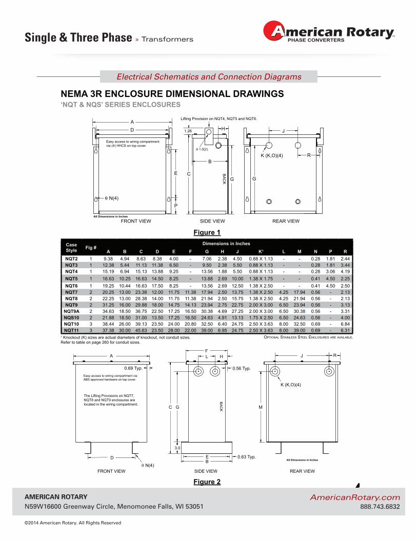
CaseStyle Fig #
Dimensions in InchesA B C D E F G H J K1 L M N P R
NQT2 1 9.38 4.94 8.63 8.38 4.00 - 7.06 2.38 4.50 0.88 X 1.13 - - 0.28 1.81 2.44NQT3 1 12.38 5.44 11.13 11.38 6.50 - 9.50 2.38 5.50 0.88 X 1.13 - - 0.28 1.81 3.44NQT4 1 15.19 6.94 15.13 13.88 9.25 - 13.56 1.88 5.50 0.88 X 1.13 - - 0.28 3.06 4.19NQT5 1 16.63 10.25 16.63 14.50 8.25 - 13.88 2.69 10.00 1.38 X 1.75 - - 0.41 4.50 2.25NQT6 1 19.25 10.44 16.63 17.50 8.25 - 13.56 2.69 12.50 1.38 X 2.50 - - 0.41 4.50 2.50NQT7 2 20.25 13.00 23.38 12.00 11.75 11.38 17.94 2.50 13.75 1.38 X 2.50 4.25 17.94 0.56 - 2.13NQT8 2 22.25 13.00 28.38 14.00 11.75 11.38 21.94 2.50 15.75 1.38 X 2.50 4.25 21.94 0.56 - 2.13NQT9 2 31.25 16.00 29.88 18.00 14.75 14.13 23.94 2.75 22.75 2.00 X 3.00 6.50 23.94 0.56 - 3.13
NQT9A 2 34.63 18.50 36.75 22.50 17.25 16.50 30.38 4.69 27.25 2.00 X 3.00 6.50 30.38 0.56 - 3.31NQS10 2 21.88 18.50 31.00 13.50 17.25 16.50 24.63 4.91 13.13 1.75 X 2.50 6.50 24.63 0.56 - 4.00NQT10 3 38.44 26.00 39.13 23.50 24.00 20.80 32.50 6.40 24.75 2.50 X 3.63 8.00 32.50 0.69 - 6.84NQT11 3 37.38 30.00 45.63 23.50 28.00 22.00 39.00 6.95 24.75 2.50 X 3.63 8.00 39.00 0.69 - 6.31
© Hammond Power Solutions Inc. Data subject to change without notice.
‘NQT & NQS’ SERIES ENCLOSURESNEMA 3R ENCLOSURE DIMENSIONAL DRAWINGS
FRONT VIEW REAR VIEWSIDE VIEWθ N(4)
BA
CK
All Dimensions in Inches
A
B
C
D E
G
FJL H
0.56 Typ.
M
R
0.63 Typ.
K (K,O)(4)
3.0
0.69 Typ.Easy access to wiring compartment viaABS approved hardware on top cover.
The Lifting Provisions on NQT7,NQT8 and NQT9 enclosures are located in the wiring compartment.
Figure 2
FRONT VIEW REAR VIEW SIDE VIEW
B
AD H
E C
K (K,O)(4)
Pθ N(4)
Lifting Provision on NQT4, NQT5 and NQT6.
BA
CK
All Dimensions in Inches
G G
J
R
1.26
Easy access to wiring compartment via (4) HHCS on top cover.
θ 1.0(2)
Figure 1
OptiOnal StainlESS StEEl EnclOSurES arE availablE.1 Knockout (K) sizes are actual diameters of knockout, not conduit sizes. Refer to table on page 260 for conduit sizes.
AmericAn rotAry N59W16600 Greenway Circle, Menomonee Falls, WI 53051
©2014 American Rotary. All Rights Reserved
AmericanRotary.com 888.743.6832
Electrical Schematics and Connection Diagrams
Single & Three Phase » Transformers
264
GENERAL INFORMATION
GEN
ERA
L IN
FOR
MAT
ION
© Hammond Power Solutions Inc. Data subject to change without notice.
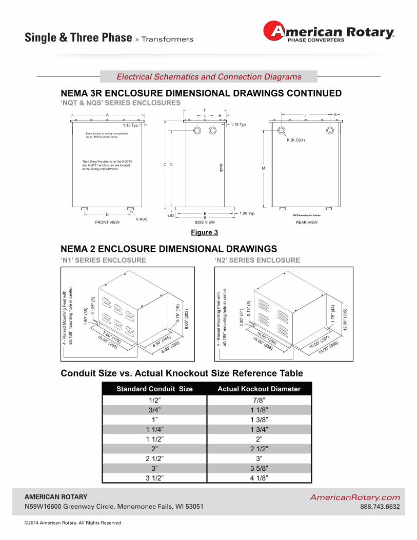
NEMA 2 ENCLOSURE DIMENSIONAL DRAWINGS
10.50” (267)
10.00” (254)12
.00”
(305
)
14.00” (356)
14.00” (356)
1.75
” (44
)
2.00
” (51
)
0.13
” (3)
4 - R
aise
d M
ount
ing
Feet
with
ø0
.188
” mou
ntin
g ho
le in
cen
ter.
6.50” (165)
7.00” (178)
8.00
” (20
3)
8.00” (203)
10.00” (254)
0.75
” (19
)
1.50
” (38
)
0.12
5” (3
)
4 - R
aise
d M
ount
ing
Feet
with
ø0
.188
” mou
ntin
g ho
le in
cen
ter.
‘N1’ SERIES ENCLOSURE ‘N2’ SERIES ENCLOSURE
Conduit Size vs. Actual Knockout Size Reference TableStandard Conduit Size Actual Kockout Diameter
1/2” 7/8”3/4” 1 1/8”1” 1 3/8”
1 1/4” 1 3/4”1 1/2” 2”
2” 2 1/2”2 1/2” 3”
3” 3 5/8”3 1/2” 4 1/8”
FRONT VIEW REAR VIEWSIDE VIEW
All Dimensions in Inches
BA
CK
Easy access to wiring compartmentvia (4) HHCS on top cover.
θ N(4)
A
B
C
D E
G
FJL H
1.19 Typ.
M
R
1.00 Typ.
K (K,O)(4)
1.53
1.13 Typ.
The Lifting Provisions on the NQT10and NQT11 enclosures are locatedin the wiring compartment.
Figure 3
‘NQT & NQS’ SERIES ENCLOSURESNEMA 3R ENCLOSURE DIMENSIONAL DRAWINGS CONTINUED
AmericAn rotAry N59W16600 Greenway Circle, Menomonee Falls, WI 53051
©2014 American Rotary. All Rights Reserved
AmericanRotary.com 888.743.6832
Electrical Schematics and Connection Diagrams
Single & Three Phase » Transformers
265
GEN
ERA
L IN
FOR
MATIO
N
GENERAL INFORMATION
Case StyleDimensions in Inches
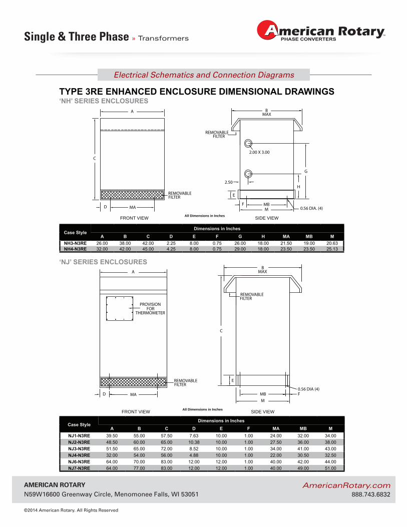
A B C D E F G H MA MB MNH3-N3RE 26.00 38.00 42.00 2.25 8.00 0.75 26.00 18.00 21.50 19.00 20.63NH4-N3RE 32.00 42.00 45.00 4.25 8.00 0.75 29.00 18.00 23.50 23.50 25.13
Case StyleDimensions in Inches
A B C D E F MA MB MNJ1-N3RE 39.50 55.00 57.50 7.63 10.00 1.00 24.00 32.00 34.00NJ2-N3RE 48.50 60.00 65.00 10.38 10.00 1.00 27.50 36.00 38.00NJ3-N3RE 51.50 65.00 72.00 8.52 10.00 1.00 34.00 41.00 43.00NJ4-N3RE 32.00 54.00 56.00 4.88 10.00 1.00 22.00 30.50 32.50NJ6-N3RE 64.00 70.00 83.00 12.00 12.00 1.00 40.00 42.00 44.00NJ7-N3RE 64.00 77.00 83.00 12.00 12.00 1.00 40.00 49.00 51.00
© Hammond Power Solutions Inc. Data subject to change without notice.
TYPE 3RE ENHANCED ENCLOSURE DIMENSIONAL DRAWINGS‘NH’ SERIES ENCLOSURES
‘NJ’ SERIES ENCLOSURES
0.56 DIA (4)FD
E
MBMA
B
C
M
A MAX
THERMOMETERFOR
PROVISION
REMOVABLEFILTER
FILTERREMOVABLE
FRONT VIEW SIDE VIEWAll Dimensions in Inches
MAX
F
E
MD 0.56 DIA. (4)MB
MA
2.00 X 3.00
H2.50
G
BA
C
REMOVABLEFILTER
FILTERREMOVABLE
FRONT VIEW SIDE VIEWAll Dimensions in Inches