Embed Size (px)
Citation preview

8/10/2019 Buckling of Bulb Flat Plates
http://slidepdf.com/reader/full/buckling-of-bulb-flat-plates 1/121
NAVAL POSTGRADUATE SCHOOL
Monterey, California
DISSERTATION
Approved for public release; distribution is unlimited
ANALYTIC EXPRESSION OF THE BUCKLING LOADS
FOR STIFFENED PLATES
WITH BULB-FLAT FLANGES
by
Archie Wilmer III
June 2003
Dissertation Supervisor: Don Danielson

8/10/2019 Buckling of Bulb Flat Plates
http://slidepdf.com/reader/full/buckling-of-bulb-flat-plates 2/121
THIS PAGE INTENTIONALLY LEFT BLANK

8/10/2019 Buckling of Bulb Flat Plates
http://slidepdf.com/reader/full/buckling-of-bulb-flat-plates 3/121
i
REPORT DOCUMENTATION PAGE Form Approved OMB No. 0704-0188 Public reporting burden for this collection of information is estimated to average 1 hour per response, including
the time for reviewing instruction, searching existing data sources, gathering and maintaining the data needed, and
completing and reviewing the collection of information. Send comments regarding this burden estimate or anyother aspect of this collection of information, including suggestions for reducing this burden, to Washington
headquarters Services, Directorate for Information Operations and Reports, 1215 Jefferson Davis Highway, Suite
1204, Arlington, VA 22202-4302, and to the Office of Management and Budget, Paperwork Reduction Project(0704-0188) Washington DC 20503.
1. AGENCY USE ONLY (Leave blank) 2. REPORT DATE June 2003
3. REPORT TYPE AND DATES COVERED Dissertation
4. TITLE AND SUBTITLE: Title (Mix case letters)nalytic Expression of the Buckling Loads for Stiffened Plates with Bulb-Flat Flanges
6. AUTHOR(S) Archie Wilmer III
5. FUNDING NUMBERS
7. PERFORMING ORGANIZATION NAME(S) AND ADDRESS(ES)
Naval Postgraduate SchoolMonterey, CA 93943-5000
8. PERFORMING
ORGANIZATION REPORT
NUMBER
9. SPONSORING / MONITORING AGENCY NAME(S) AND ADDRESS(ES)
N/A10. SPONSORING / MONITORING
AGENCY REPORT NUMBER
11. SUPPLEMENTARY NOTES The views expressed in this thesis are those of the author and do not reflect the official policy or position of the Department of Defense or the U.S. Government.
12a. DISTRIBUTION / AVAILABILITY STATEMENT Approved for public release; distribution is unlimited
12b. DISTRIBUTION CODE A
13. ABSTRACT (maximum 200 words) The subject of this research is the buckling behavior of a simply supported rectangular plate, with a bulb-flatstiffener attached to one side of the plate. The plate structure is subjected to axial compression that increases to
the buckling load. The stiffener cross-section has a thin web and a bulb-flat flange that extends to one side of the
web. Results of the investigation include planar property formulas for the asymmetric flange geometry, an
analytic expression for the Saint Venant torsional constant of the flange cross-section, and an analytic expressionfor the buckling load corresponding to a tripping mode of the structure. The torsional constant for the bulb-flat
stiffener is 15% - 23% higher than understood previously. The analytic expression for the buckling load of the
bulb-flat stiffened plates considered in this investigation yields values that are 2% - 6% higher than finite element
results. It is also shown that the buckling load of a plate with a bulb-flat stiffener is 3% - 4% less than that of a plate with a T-flange stiffener with the same cross-sectional area. At the onset of stiffener tripping, the torsionally
superior bulb-flat tends to bend laterally, while the flexurally superior T-flange tends to twist.
15. NUMBER OF
PAGES 121
14. SUBJECT TERMS Stiffened Plates, Bulb-Flat, Torsion, Saint Venant, Buckling Load
16. PRICE CODE
17. SECURITY
CLASSIFICATION OFREPORT
Unclassified
18. SECURITY
CLASSIFICATION OF THISPAGE
Unclassified
19. SECURITY
CLASSIFICATION OFABSTRACT
Unclassified
20. LIMITATION
OF ABSTRACT
UL
NSN 7540-01-280-5500 Standard Form 298 (Rev. 2-89)
Prescribed by ANSI Std. 239-18

8/10/2019 Buckling of Bulb Flat Plates
http://slidepdf.com/reader/full/buckling-of-bulb-flat-plates 4/121
ii
THIS PAGE INTENTIONALLY LEFT BLANK

8/10/2019 Buckling of Bulb Flat Plates
http://slidepdf.com/reader/full/buckling-of-bulb-flat-plates 5/121
iii
Approved for public release; distribution is unlimited
ANALYTIC EXPRESSION OF THE BUCKLING LOADS FOR STIFFENED
PLATES WITH BULB-FLAT FLANGES
Archie Wilmer IIILieutenant Colonel, United States Army
B.S., United States Military Academy, 1982
M.S., Naval Postgraduate School, 1994
Submitted in partial fulfillment of the
requirements for the degree of
DOCTOR OF PHILOSOPHY IN APPLIED MATHEMATICS
from the
NAVAL POSTGRADUATE SCHOOL
June 2003
Author: Archie Wilmer III
Approved by:
Don DanielsonProfessor of Mathematics
Dissertation Supervisor/Committee Chair
David Canright Young Kwon
Professor of Mathematics Professor of Mech. Eng.
Fariba Fahroo Wei Kang
Professor of Mathematics Professor of Mathematics
Approved by: Clyde Scandrett, Chair, Department of Mathematics
Approved by: Carson K. Eoyang, Associate Provost for Academic Affairs

8/10/2019 Buckling of Bulb Flat Plates
http://slidepdf.com/reader/full/buckling-of-bulb-flat-plates 6/121
iv
THIS PAGE INTENTIONALLY LEFT BLANK

8/10/2019 Buckling of Bulb Flat Plates
http://slidepdf.com/reader/full/buckling-of-bulb-flat-plates 7/121
v
ABSTRACT
The subject of this research is the buckling behavior of a simply supported
rectangular plate, with a bulb-flat stiffener attached to one side of the plate. The plate
structure is subjected to axial compression that increases to the buckling load. The
stiffener cross-section has a thin web and a bulb-flat flange that extends to one side of the
web. Results of the investigation include planar property formulas for the asymmetric
flange geometry, an analytic expression for the Saint Venant torsional constant of the
flange cross-section, and an analytic expression for the buckling load corresponding to a
tripping mode of the structure. The torsional constant for the bulb-flat stiffener is 15% -
23% higher than understood previously. The analytic expression for the buckling load ofthe bulb-flat stiffened plates considered in this investigation yields values that are 2% -
6% higher than finite element results. It is also shown that the buckling load of a plate
with a bulb-flat stiffener is 3% - 4% less than that of a plate with a T-flange stiffener with
the same cross-sectional area. At the onset of stiffener tripping, the torsionally superior
bulb-flat tends to bend laterally, while the flexurally superior T-flange tends to twist.

8/10/2019 Buckling of Bulb Flat Plates
http://slidepdf.com/reader/full/buckling-of-bulb-flat-plates 8/121
vi
THIS PAGE INTENTIONALLY LEFT BLANK

8/10/2019 Buckling of Bulb Flat Plates
http://slidepdf.com/reader/full/buckling-of-bulb-flat-plates 9/121
vii
TABLE OF CONTENTS
I. INTRODUCTION........................................................................................................1
A. INTENT AND SYNOPSIS..............................................................................1 B. BACKGROUND ..............................................................................................2
C. LITERATURE SEARCH ...............................................................................2
D. NOTATION AND CONVENTIONS .............................................................4
II. BULB-FLAT FLANGE CROSS-SECTION PROPERTIES...................................7
A. INTRODUCTION............................................................................................7
B. CROSS-SECTIONAL BOUNDARY AND PLANAR PROPERTIES .......7
C. TORSIONAL RIGIDITY .............................................................................13
1. Exact Value Using the Stress Function Method..............................14
2. Approximate Expressions: Lower and Upper Bounds...................16
3. Approximate Expressions: k*A
4
/I....................................................19 4. Idealization .........................................................................................24
D. VALIDATION USING FINITE ELEMENT MODELS............................26
III. STIFFENED PLATE BUCKLING..........................................................................35
A. INTRODUCTION..........................................................................................35
B. ASSUMPTIONS.............................................................................................35
C. ENERGY PRINCIPLE .................................................................................36
D. SIMPLY SUPPORTED RECTANGULAR STIFFENED PLATE...........37
1. Energy Functional..............................................................................43
2. Approximate Solution........................................................................43
3. General Buckling Mode and Load ...................................................46
4. Buckling Expression Summary ........................................................51 5. Example ..............................................................................................52
E. FINITE ELEMENT ANALYSIS .................................................................54
IV. FINDINGS AND CONCLUSIONS..........................................................................73
APPENDIX A. THE BULB-FLAT FLANGE HEIGHT FORMULA.....................77
APPENDIX B. THE PLANAR PROPERTY FORMULAS.....................................81
APPENDIX C. DATA TABLES .................................................................................87
1. DATA FOR BULB-FLAT FLANGE CROSS-SECTION .........................87
2. DATA FOR THE BULB-FLAT STIFFENER CROSS-SECTION ..........90
3. DATA FOR THE STIFFENED PLATE MODELS ...................................93 LIST OF REFERENCES......................................................................................................99
INITIAL DISTRIBUTION LIST .......................................................................................101

8/10/2019 Buckling of Bulb Flat Plates
http://slidepdf.com/reader/full/buckling-of-bulb-flat-plates 10/121
viii
THIS PAGE INTENTIONALLY LEFT BLANK

8/10/2019 Buckling of Bulb Flat Plates
http://slidepdf.com/reader/full/buckling-of-bulb-flat-plates 11/121
ix
LIST OF FIGURES
FIGURE 1 BULB-FLAT STIFFENER CROSS-SECTION................................................................ 8
FIGURE 2 BULB-FLAT FLANGE GEOMETRY ........................................................................... 9FIGURE 3 MSC PATRAN PICTURE OF BULB-FLAT FLANGE BOUNDARY POINTS FOR CROSS-
SECTION PROPERTIES.................................................................................................... 9FIGURE 4 IDEALIZING AN ELLIPSE AS A RECTANGLE .......................................................... 25
FIGURE 5 MSC PATRAN GRAPH AND DATA OF A HORIZONTAL BULB-FLAT FLANGE........... 27
FIGURE 6 MSC PATRAN GRAPH AND DATA OF AN AREA-EQUIVALENT ANGLE FLANGE ..... 27FIGURE 7 MSC PATRAN GRAPHS OF BULB-FLAT STIFFENER BOUNDARY POINTS FOR CROSS-
SECTION PROPERTIES.................................................................................................. 30
FIGURE 8 MSC PATRAN GRAPH AND DATA OF A BULB-FLAT STIFFENER MODEL................ 31
FIGURE 9 MSC PATRAN GRAPH AND DATA OF AN AREA-EQUIVALENT ANGLE STIFFENER
MODEL ....................................................................................................................... 31
FIGURE 10 TOP VIEW OF FIBER CURVATURE DURING BUCKLING ........................................ 39FIGURE 11 FLANGE CROSS-SECTION WITH CENTROIDAL COORDINATE SYSTEM.................. 40FIGURE 12 PLATE AND WEB DEFLECTION WHEN THERE IS NO FLANGE ............................... 46
FIGURE 13 MODE 1 DEFLECTION ....................................................................................... 48
FIGURE 14 MODE 2 DEFLECTION ....................................................................................... 49FIGURE 15 MODE 3 DEFLECTION ....................................................................................... 49
FIGURE 16 MAPLE 8 GRAPH OF THE BUCKLING LOAD FOR THE BULB-FLAT STIFFENED PLATE
EXAMPLE.................................................................................................................... 53
FIGURE 17 STIFFENED PLATE PRE-BUCKLING AND BUCKLING MODE .................................. 55FIGURE 18 MSC NASTRAN PICTURE 1 FOR STIFFENED PLATE MODEL 1B .......................... 64
FIGURE 19 MSC NASTRAN PICTURE 2 FOR STIFFENED PLATE MODEL 1B .......................... 64
FIGURE 20 MAPLE 8 GRAPH 1 OF THE BUCKLING LOADS FOR MODEL 1 ............................. 65FIGURE 21 MAPLE 8 GRAPH 2 OF THE BUCKLING LOADS FOR MODEL 1 ............................. 66
FIGURE 22 MAPLE 8 GRAPH OF THE BUCKLING LOAD FOR THE BULB-FLAT CONFIGURATION
OF MODEL 1............................................................................................................... 67FIGURE 23 MSC NASTRAN PICTURES SHOWING THE BUCKLING BEHAVIOR OF THE WEBS
WITH BULB-FLAT FLANGES FOR MODELS 2B (LEFT) AND 3B (RIGHT) ......................... 68
FIGURE 24 MSC NASTRAN PICTURES SHOWING THE BUCKLING BEHAVIOR OF THE WEBS
WITH BULB-FLAT FLANGES FOR MODELS 4B (LEFT), 5B (CENTER ), AND 6B (RIGHT)... 69
FIGURE 25 MSC NASTRAN PICTURES SHOWING THE BUCKLING BEHAVIOR OF THE WEBS
WITH T-FLANGES FOR MODELS 4T (LEFT) AND 6T (RIGHT) ........................................ 69
FIGURE 26 BULB-FLAT FLANGE GEOMETRY ....................................................................... 78
FIGURE 27 MSC PATRAN BULB-FLAT FLANGE BOUNDARY POINTS FOR CROSS-SECTIONPROPERTIES................................................................................................................ 78

8/10/2019 Buckling of Bulb Flat Plates
http://slidepdf.com/reader/full/buckling-of-bulb-flat-plates 12/121
x
THIS PAGE INTENTIONALLY LEFT BLANK

8/10/2019 Buckling of Bulb Flat Plates
http://slidepdf.com/reader/full/buckling-of-bulb-flat-plates 13/121
xi
LIST OF TABLES
TABLE 1 SAINT VENANT APPROXIMATE EXPRESSION FOR COMMON CROSS-SECTIONS ....... 19
TABLE 2 FINITE ELEMENT RESULTS FOR BULB-FLAT FLANGE CROSS-SECTIONS ................. 22TABLE 3 FINITE ELEMENT RESULTS FOR BULB-FLAT FLANGE CROSS-SECTIONS (CONT) ..... 23
TABLE 4 COMPARISON OF FLANGE VALUES ....................................................................... 28TABLE 5 COMPARISON OF STIFFENER VALUES ................................................................... 32
TABLE 6 R ESULTS FOR THE BULB-FLAT STIFFENED PLATE EXAMPLE ................................. 54
TABLE 7 SUMMARY OF STIFFENED PLATE MODEL 1 PARAMETERS ..................................... 58TABLE 8 SUMMARY OF STIFFENED PLATE MODEL 2 PARAMETERS ..................................... 59
TABLE 9 SUMMARY OF STIFFENED PLATE MODEL 3 PARAMETERS ..................................... 59
TABLE 10 SUMMARY OF STIFFENED PLATE MODEL 4 PARAMETERS ................................... 60
TABLE 11 SUMMARY OF STIFFENED PLATE MODEL 5 PARAMETERS ................................... 60TABLE 12 SUMMARY OF STIFFENED PLATE MODEL 6 PARAMETERS ................................... 60
TABLE 13 MODEL 1 INTERMEDIATE RESULTS .................................................................... 61TABLE 14 MODEL 2 INTERMEDIATE RESULTS .................................................................... 61TABLE 15 MODEL 3 INTERMEDIATE RESULTS .................................................................... 62
TABLE 16 MODEL 4 INTERMEDIATE RESULTS .................................................................... 62
TABLE 17 MODEL 5 INTERMEDIATE RESULTS .................................................................... 63TABLE 18 MODEL 6 INTERMEDIATE RESULTS .................................................................... 63
TABLE 19 NO FLANGE FE RESULTS ................................................................................... 70
TABLE 20 BULB-FLAT FE RESULTS.................................................................................... 70
TABLE 21 CIRCULAR FE RESULTS ..................................................................................... 70TABLE 22 T-FLANGE FE RESULTS...................................................................................... 70
TABLE 23 DATA FOR FLANGE MODEL 1 IN TABLE 2 (UNITS IN MM) .................................. 87
TABLE 24 DATA FOR FLANGE MODEL 3 IN TABLE 2 (UNITS IN MM) .................................. 87TABLE 25 DATA FOR FLANGE MODEL 5 IN TABLE 2 (UNITS IN MM) .................................. 88
TABLE 26 DATA FOR FLANGE MODEL 7 IN TABLE 2 (UNITS IN MM) .................................. 88
TABLE 27 DATA FOR FLANGE MODEL 8 IN TABLE 2 (UNITS IN MM) .................................. 88TABLE 28 DATA FOR FLANGE MODEL 10 IN TABLE 2 (UNITS IN MM) ................................ 89
TABLE 29 DATA FOR FLANGE MODEL 12 IN TABLE 2 (UNITS IN MM) ................................ 89
TABLE 30 DATA FOR FLANGE MODEL 14 IN TABLE 2 (UNITS IN MM) ................................ 89TABLE 31 DATA FOR FIRST STIFFENER IN TABLE 5 (UNITS IN MM) ..................................... 90
TABLE 32 DATA FOR SECOND STIFFENER IN TABLE 5 (UNITS IN MM) ................................. 90
TABLE 33 DATA FOR THIRD STIFFENER IN TABLE 5 (UNITS IN MM) .................................... 91
TABLE 34 DATA FOR FOURTH STIFFENER IN TABLE 5 (UNITS IN MM) ................................. 91
TABLE 35 DATA FOR FIFTH STIFFENER INTABLE 5 (UNITS IN MM)...................................... 91TABLE 36 DATA FOR SIXTH STIFFENER IN TABLE 5 (UNITS IN MM) .................................... 92
TABLE 37 DATA FOR SEVENTH STIFFENER IN TABLE 5 (UNITS IN MM) ............................... 92TABLE 38 DATA FOR EIGHTH STIFFENER IN TABLE 5 (UNITS IN MM).................................. 92
TABLE 39 DATA FOR ANGLE STIFFENER IN FIGURE 9 (UNITS IN MM).................................. 93TABLE 40 DATA FOR STIFFENED PLATE MODELS 1-3 WITH NO FLANGE (UNITS IN INCHES). 93
TABLE 41 DATA FOR STIFFENED PLATE MODELS 4-6 WITH NO FLANGE (UNITS IN INCHES). 93
TABLE 42 DATA FOR BULB-FLAT STIFFENED PLATE MODEL 1B (UNITS IN INCHES) ............. 94

8/10/2019 Buckling of Bulb Flat Plates
http://slidepdf.com/reader/full/buckling-of-bulb-flat-plates 14/121
xii
TABLE 43 DATA FOR BULB-FLAT STIFFENED PLATE MODEL 2B (UNITS IN INCHES) ............. 94
TABLE 44 DATA FOR BULB-FLAT STIFFENED PLATE MODEL 3B (UNITS IN INCHES) ............. 94TABLE 45 DATA FOR BULB-FLAT STIFFENED PLATE MODEL 4B (UNITS IN INCHES) ............. 94
TABLE 46 DATA FOR BULB-FLAT STIFFENED PLATE MODEL 5B (UNITS IN INCHES) ............. 95
TABLE 47 DATA FOR BULB-FLAT STIFFENED PLATE MODEL 6B (UNITS IN INCHES) ............. 95
TABLE 48 DATA FOR CIRCULAR FLANGE STIFFENED PLATE MODEL 1C (UNITS IN INCHES) .95TABLE 49 DATA FOR CIRCULAR FLANGE STIFFENED PLATE MODEL 2C (UNITS IN INCHES) .96
TABLE 50 DATA FOR CIRCULAR FLANGE STIFFENED PLATE MODEL 3C (UNITS IN INCHES) .96
TABLE 51 DATA FOR CIRCULAR FLANGE STIFFENED PLATE MODEL 4C (UNITS IN INCHES) .96TABLE 52 DATA FOR CIRCULAR FLANGE STIFFENED PLATE MODEL 5C (UNITS IN INCHES) .96
TABLE 53 DATA FOR CIRCULAR FLANGE STIFFENED PLATE MODEL 6C (UNITS IN INCHES) .96
TABLE 54 DATA FOR T-FLANGE STIFFENED PLATE MODELS 1T, 2T, AND 3T (UNITS IN
INCHES)...................................................................................................................... 97
TABLE 55 DATA FOR T-FLANGE STIFFENED PLATE MODEL 4T, 5T, AND 6T (UNITS IN INCHES)
................................................................................................................................... 97

8/10/2019 Buckling of Bulb Flat Plates
http://slidepdf.com/reader/full/buckling-of-bulb-flat-plates 15/121
xiii
ACKNOWLEDGMENTS
I praise God, Christ Jesus, from whom all blessings flow.
I acknowledge the assistance of Professor Don Danielson who supervised this
work and to whom I am deeply grateful. His expert advice and mentoring support are
sincerely appreciated. I acknowledge and am truly appreciative for the intellectual
support and camaraderie of Commander Vince VanJoolen and Professor Bard Mansager.
Their fellowship during the pursuit of this degree was priceless. I acknowledge the
support of Dr. David Kihl of the Naval Surface Warfare Center, Carderock Division, for
his interest and suggestions. I thank Geoff Lofthouse and Barb Johnson, Corus Group,
for their interest and support. I thank Cassandra Radigan, Patran/Nastran university
coordinator, Joe Satkunknanthan, Patran/Nastran technician, Debbi Kreider, and Ron Del
Presto, computer specialists, for their helpful assistance.
I am also grateful to Greater Victory Temple, COGIC of Seaside, pastor Bishop
W.W. Hamilton, and First Baptist Church of Pacific Grove, pastor Reverend James
Calloway for their spiritual support. I acknowledge the many family, friends, and others
who have prayed and encouraged me in this undertaking.
Dedicated to my loving wife LaTressia and my darling daughter Sterling, thank
you for your love, prayers, and sacrifices.

8/10/2019 Buckling of Bulb Flat Plates
http://slidepdf.com/reader/full/buckling-of-bulb-flat-plates 16/121
xiv
THIS PAGE INTENTIONALLY LEFT BLANK

8/10/2019 Buckling of Bulb Flat Plates
http://slidepdf.com/reader/full/buckling-of-bulb-flat-plates 17/121
xv
EXECUTIVE SUMMARY
Understanding the elastic stability of stiffened plate structures is of great interest
in the design of bridges, buildings, automobiles, aircraft, naval vessels, and offshore
platforms. This work contributes formulas intended for the mechanical engineer, analyst,
and educator involved in the analysis or design of the bulb-flat cross-section and simply
supported stiffened rectangular plate.
Chapter I comments on the intent and synopsis of this investigation. Brief
comments address the background for the study and literature search for published
material related to the investigation. A list of notation and conventions is included.
Chapter II presents the application of multivariable calculus to derive planar
property formulas for the bulb-flat cross-section. Appendices A and B contain additional
derivations and expressions related to the formulas. The torsional constant is one of the
key property values involved in the analysis of stiffened plate structures. No exact
expression exists in published literature for the torsional constant of the bulb-flat cross-
section. Saint Venant’s work on an approximate expression for the torsional constant of
a solid cross-section provides a method to develop an accurate one-term approximate
formula applicable to bulb-flat cross-sections produced by Corus Group, one of the
world’s leading producers of bulb-flat profiled metals. Presented is a discussion on the
idealization method to approximate the torsional constant.
Chapter III presents the application of elasticity theory and energy methods to
derive a general expression for the buckling load due to the stiffener tripping of a simply
supported rectangular stiffened plate subjected to axial compression. The general
expression for the buckling load involves a constant called . The buckling load and
values are determined graphically. The value of indicates the stiffener deflection
behavior at the onset of stiffener tripping. Three special expressions provide initial
approximations for the upper bound of the critical buckling load value. Concepts applied
in the derivation include extremum principles in mechanics, the energy criterion, calculus

8/10/2019 Buckling of Bulb Flat Plates
http://slidepdf.com/reader/full/buckling-of-bulb-flat-plates 18/121
xvi
of variations, the Rayleigh-Ritz method, and other topics in applied mathematics and
physics. The chapter also presents finite element analyses of several stiffened plate
models. The results are compared to predictions made using derived formulas. MSC
Nastran 2001/Patran 2001 r3 finite element software and the Maple 8 computer
environment are the primary analysis and computational tools used in this investigation.
Appendix C contains data tables used to represent the finite element models.
Chapter IV summarizes the major findings and conclusions of this work. This
investigation:
• Determines boundary equations for the bulb-flat flange cross-section.
• Derives planar property value expressions.
• Determines an approximate torsional constant expression that is more accurate
than idealizing.
• Demonstrates that the torsional property of the bulb-flat stiffener is better than
previously understood. The torque-carrying capacity of a bulb-flat stiffener
(possessing no structural flaws) is greater than that of an area-equivalent angle
stiffener.
• Derives a general expression to predict the buckling load due to stiffener
tripping of a simply supported rectangular stiffened plate subjected to axial
compression. The predicted value is less than 6% higher than the finite
element result.
• Demonstrates that the buckling behavior of the bulb-flat stiffened plate is
unlike that of the T-flange configuration. The bulb-flat tends to buckle
laterally and have a lower buckling load value than an area-equivalent T-
flange stiffened plate.
Chapter IV lists future research directions that include:
• Investigating methods to determine the value by other than graphical
means.
• Investigating the use of conformal mapping to determine the exact expression
for the bulb-flat torsional constant.
• Investigating solutions to the torsion problem for asymmetric cross-sections.

8/10/2019 Buckling of Bulb Flat Plates
http://slidepdf.com/reader/full/buckling-of-bulb-flat-plates 19/121
xvii
• Conducting investigations of other flange cross-sections, multiple stiffener
configurations, and grillages.
• Conducting further investigations of the T flange by treating the flange as a
thin web plate strip instead of a beam. This treatment may achieve more
accurate predictions for the T-flange buckling loads.
• Developing algorithms that increase efficiency in stiffened plate analysis and
design.

8/10/2019 Buckling of Bulb Flat Plates
http://slidepdf.com/reader/full/buckling-of-bulb-flat-plates 20/121
xviii
THIS PAGE INTENTIONALLY LEFT BLANK

8/10/2019 Buckling of Bulb Flat Plates
http://slidepdf.com/reader/full/buckling-of-bulb-flat-plates 21/121
1
I. INTRODUCTION
A. INTENT AND SYNOPSIS
This work presents an investigation into the structural behavior and collapse of a
stiffened plate panel where the stiffener is thin-webbed and the flange of the stiffener has
a bulb-flat cross-section. Chapter I includes brief comments on the background and
motivation for the study. Chapter II presents analytic expressions for the cross-sectional
properties of the bulb-flat flange. For brevity, Appendices A and B contain key
derivations related to the property expressions. Cross-sectional properties include area,
centroid, moments of inertia, and torsional constant. The property values for the flange
cross-section are needed in the analytic formulas to determine the buckling load of thestiffened plate. Chapter II presents a comparison of the bulb-flat stiffener configuration
to the angle flange configuration to show that the torsional property of the bulb-flat
stiffener is better than previously understood. Chapter III presents a comparison of the
bulb-flat stiffened plate configuration to the T-flange configuration to show that their
buckling behaviors are different given the same cross-sectional area. These comparisons
provide better discernment of the buckling characteristics of stiffened plates. Chapter III
contains the development of a buckling load formula for a stiffened plate resulting from
stiffener tripping. The onset of stiffener tripping negates the stiffener’s support to the
plate panel and leads to eventual collapse of the structure. The aim is to develop an
analytic expression for the buckling load of a rectangular stiffened plate, with one or
more parallel bulb-flat stiffeners attached to one side, where the plate structure is
subjected to axial compression. The focus of the analysis is on a rectangular plate
stiffened with one bulb-flat stiffener. The results can be extended and applied to plate
structures with more than one stiffener. Energy methods are used, as an alternative to
vector methods, to analyze the displacement and deflection behavior of the stiffened plate
model. The chapter contains finite element analyses of several stiffened plate models
using MSC Nastran 2001/Patran 2001-r3 software. Finite element analysis results are
compared to formula results to assess formula accuracy and the validation of results
presented earlier.

8/10/2019 Buckling of Bulb Flat Plates
http://slidepdf.com/reader/full/buckling-of-bulb-flat-plates 22/121
2
B. BACKGROUND
Stiffened plates are basic structural components of many items. Metal stiffened
plates can be found on bridges, buildings, automobiles, aircraft, naval vessels, and
offshore platforms. In ship design, a stiffener is a metal structure composed of a web and
flange. Stiffeners placed on one or both sides of a plate add strength and hinder overall
collapse of the plate panel. Because of the structural complexity of stiffened plates,
understanding their elastic instability is of great importance to ship designers and requires
careful study.
Stiffened plate investigations occur in three general forms: theoretical, using
classical and emerging theory; numerical, using finite element methods and computer-
aided simulation; and experimental, using actual grillages. It is enlightening to compare
the results of all three general forms of investigation. With regard to bulb-flat stiffened
plates, it appears that most of what is known of their behavior comes from numerical and
experimental investigations. This investigation attempts to contribute new theoretical
insights into the behavior of bulb-flat stiffened plates.
The use of bulb-flat plate stiffeners in ship design is said to reduce building time
and maintenance cost. Companies that produce bulb-flat plate stiffeners manufacture
each stiffener as a single unit, which reportedly results in less production cost compared
to welded or fabricated stiffeners. Additionally, the curved surface of the bulb-flat traps
less moisture resulting in less corrosion. The shape of the bulb-flat stiffener is much
easier to inspect, weld, and paint. These benefits save significant repair and maintenance
costs over the lifetime of the vessel.
Advocates of bulb-flat structures applaud the advantages gained by using bulb-
flats. The Jiangyin Bridge in China and the Oresund Bridge that links Denmark to
Sweden are major constructions incorporating bulb-flat geometry.
C. LITERATURE SEARCH
In his bibliography, Langhaar includes a list of books and articles that well serve
the reader interested in general developments and special topics in mechanics. Notable is
the history and theory of plate stability discussed thoroughly in Bleich [1], who
acknowledges G.H. Bryan as the originator of the study of plate stability under edge

8/10/2019 Buckling of Bulb Flat Plates
http://slidepdf.com/reader/full/buckling-of-bulb-flat-plates 23/121
3
compression. Bleich’s discussion on rectangular plates under uniform axial compression
and stiffened plates under axial compression are applicable to this investigation. His
demonstration on the theory of buckling of centrally loaded columns by torsion and
flexure serves as a fundamental basis for the buckling analysis in Chapter III.
A series of papers by Chou and Chapman [3] are noteworthy because they address
the buckling behavior of bulb-flat stiffened plates. Their study presents an improved
design method, iterative in nature, for determining the buckling load of the structure
against the torsional buckling of the stiffener. They validate the study using FINASIC, a
finite element program, and compare the results to actual tests on cruciform struts and
box columns containing bulb-flat stiffeners.
An interesting aspect of their theoretical analysis is the idealization of the bulb-
flat flange as an equivalent angle flange. That is, they treat the bulb-flat cross-section
like a rectangular cross-section in regards to the bulb-flat torsional and warping
properties. Chapter II addresses this treatment and shows that idealization imputes error
in the calculation of the bulb-flat cross-section’s torsional rigidity. Developing and using
expressions that maintain the bulb-flat geometry yields more accurate cross-sectional
property data resulting in a more accurate analysis.
Other work relevant to this investigation includes research and a series of papers
by Danielson et al. [5, 6, 7, 8, and 9] analyzing the tripping of a beam attached to a plate
under lateral pressure loading. His investigation includes the assumption that the
stiffener behaves like a thin-walled open section beam. Applying nonlinear beam theory,
he obtains an analytic expression for the buckling of stiffened plate structures under
longitudinal compression. His work includes investigations of the buckling load of ship
grillages under axial compression with and without lateral pressure [14 and 15]. He uses
finite element based eigenvalue analysis to gain insight into the ways the buckling loads
and modes vary given the grillage dimensions. In new unpublished work, he extends his
previous work by re-deriving buckling load formulas that incorporate different
assumptions about buckling behavior.

8/10/2019 Buckling of Bulb Flat Plates
http://slidepdf.com/reader/full/buckling-of-bulb-flat-plates 24/121
4
D. NOTATION AND CONVENTIONS
f A Area of the flange
s A f w A A+ , Area of the stiffener
w A Area of the web
D ( )
3
212 1
Eh
ν −, Bending stiffness coefficient
E Modulus of elasticity of the material (force/length2)
G ( )2 1
E
ν +, Shear modulus, modulus of rigidity
, , xx yy c I I I Moments of inertia about the axes and centroid in ( ), x y
coordinate system (length4)
xy I Product of inertia about the origin in ( ), x y coordinate system
(length4)
, xc yc I I Moments parallel to the axes through the centroid in ( ), x y
coordinate system (length4)
xyc I Product of inertia about the centroid in ( ), y coordinate system
(length4
), x y M Bending moments (force/length) or first moments (length
3)
R Region defined by the cross-section of the flange (length2)
f h Height of flange (length)
wh Height of the web (length)
sh w f h h+ , Height of the stiffener (length)
m Slope of a line or line segment
1,r r Radius of curvature (length)
bf t Thickness of the flange bulb (length)
t w bf t t + , Maximum thickness of flange (length)

8/10/2019 Buckling of Bulb Flat Plates
http://slidepdf.com/reader/full/buckling-of-bulb-flat-plates 25/121
5
pt Thickness of plate (length)
wt Thickness of the web (length)
, x y Bulb-flat flange coordinate system
,c c x y Bulb-flat flange coordinate system where the centroid coincides
with the origin of the coordinate system
1 2 3, , x x x Plate structure coordinate system
,α θ Angle (radians)
ν Poisson’s ratio
σ Normal stress (force/length2)

8/10/2019 Buckling of Bulb Flat Plates
http://slidepdf.com/reader/full/buckling-of-bulb-flat-plates 26/121
6
THIS PAGE INTENTIONALLY LEFT BLANK

8/10/2019 Buckling of Bulb Flat Plates
http://slidepdf.com/reader/full/buckling-of-bulb-flat-plates 27/121
7
II. BULB-FLAT FLANGE CROSS-SECTION PROPERTIES
A. INTRODUCTION
A wealth of knowledge exists on the behavior of stiffeners with common
geometries such as I, T, Z, angle, channel, and flat-bar cross-sections. These common
geometries possess certain cross-sectional properties that are relatively easy to derive.
Studying uncommon cross-sections, such as the bulb-flat cross-section, is often difficult
because obtaining the section properties of such cross-sections requires considerably
more effort.
This chapter presents expressions to determine the planar properties of the bulb-
flat cross-section. Subsequent analysis of the stiffened plate structure requires knowledge
of the planar property values for a specified cross-section.
B. CROSS-SECTIONAL BOUNDARY AND PLANAR PROPERTIES
Consider the cross-section of a bulb-flat that extends to one side of the web as
shown in Figures 1-3. Figure 1 shows the entire stiffener cross-section composed of the
bulb-flat flange and thin web. Figure 2 and Figure 3 show only the flange horizontally
oriented. Five independent variables ( wt , bf t , r , 1r , and α ) uniquely determine the
flange boundary. Using both Figure 2 and Figure 3, the following labeling is established.
The variable wt denotes the web thickness defined by the vertical distance between point
4 and point 5. The variable bf t denotes the bulb thickness defined by the vertical distance
between point 9 and a point horizontal to point 5. The total flange thickness (at its
maximum value) is denoted by f w bf t t t = + defined by the vertical distance between point
9 and the line formed by points 3 and 4. The corners of the cross-section have radii of
curvature r and 1r . Points 5-6-7 and 8-9-10 define the corners with radius of curvature
r . Points 1-2-3 define the corner with radius 1r . The cross-section has a flat portion
defined by the points 7 and 8, that slopes α degrees from the y -axis.

8/10/2019 Buckling of Bulb Flat Plates
http://slidepdf.com/reader/full/buckling-of-bulb-flat-plates 28/121
8
Figure 1 Bulb-flat stiffener cross-section
wt
sh
f h
wh
3 x
2 x
8/10/2019 Buckling of Bulb Flat Plates
http://slidepdf.com/reader/full/buckling-of-bulb-flat-plates 29/121
9
Figure 2 Bulb-flat flange geometry
Figure 3 MSC Patran picture of bulb-flat flange boundary
points for cross-section properties
bf t
wt
f h
α
1r
r
r
y

8/10/2019 Buckling of Bulb Flat Plates
http://slidepdf.com/reader/full/buckling-of-bulb-flat-plates 30/121
10
Let h denote the flange height. The boundary of the flange includes two vertical sides
0 x = and f h= , where
( )tan 1 2 tan 2sec
f bf
h t r α α α = + − + (1)
and 0 / 2α π < < 1 (see Appendix A). The upper and lower boundaries of the cross-
section are defined by the following functions. The upper boundary of the flange cross-
section is given by:
( )
( ) ( ) ( )
( ) ( )
( ) ( ) ( )
22
1
2
22
3
, 0 cos
cot , cos cos
, cos
cot csc 1
w bf
w bf f
w f f f
f x t t r r x r x r r
f x x t t r r r x h r
f x t r r x h h r x h
f x
α
α α α α α
α
= + − + − − ≤ < +
= − + + + + ≤ < −
= + − − − − ≤ ≤
= + −
(2)
The lower boundary of the flange cross-section is given by:
( ) ( ) ( )
( )
22
1 1 1 1 1
2 1
, 0
0, f
g x r r x r x r g x
g x r x h
= − − − ≤ <
= = ≤ ≤
(3)
Given the upper, lower, and vertical boundaries, the cross-section of the flange is
the bounded region R defined by 0 f h≤ ≤ , ( ) ( ) g x y f x≤ ≤ , with ( ) f x and ( ) g x on
0, x h ∈ . The flange cross-sectional planar properties can be calculated from the
following integral expression where ,m n are nonnegative integers (see Appendix B for
details of the integral derivation):
( )
( )
( ) ( ){ }1 1
0 0
1
1
f f h h f xn nm n m n m
R g x
x y dA x y dy dx x f x g x dxn
+ +
= = − +
∫∫ ∫ ∫ ∫ (4)
Substitution of expressions (2) and (3) into expression (4) yields
1 As 0α → , the flange geometry resembles an angle flange with a rounded end of radius r whosecross-section properties could be approximated with an equivalent rectangle.

8/10/2019 Buckling of Bulb Flat Plates
http://slidepdf.com/reader/full/buckling-of-bulb-flat-plates 31/121
11
( ) ( )
( )
( ) ( )
( ) ( )
21
2
cos1
cos
01
2
012
1
2
1sin cos cos
1
1
cot cot csc1
1sin cos cos
1
11 sin 1 cos cos
1
f
nmm n
w bf
R
h r n
m
w bf r r
m n
f w
m nm n
x y dA r r t t r r r d n
x x t t r r r dxn
h r t r r r d n
r d n
π α
π
α
α
π α
π
θ θ θ θ
α α α
θ θ θ θ
θ θ θ θ
−
+
−
−
+
+
+
−
++ +
−
= + + − ++
+ − + + + + −+
+ + + −+
− + −+
∫∫ ∫
∫
∫
∫
(5)
where
( )tan 1 2 tan 2sec
0 , , 02 2 2
f bf
f
h t r
h
α α α
π π π α θ
= + − +
< < − ≤ ≤ ≤ ≤
Throughout this investigation, the planar property values for the bulb-flat flange are
calculated using integral expression (5). Appendix B contains a summary of the planar
property formulas. For brevity, the expansion of each general planar property formula is
omitted.
Integral expression (5) can be specialized for a class of bulb-flat flange cross-
sections by assigning a value to one or more of the variables. For example, by setting
/ 6α π = , integral expression (5) defines planar property formulas for a class of bulb-flat
cross-sections with a 30o slope. Additionally, if the radius of curvature of the cross-
section corner 1r is assumed to be one-tenth of the web thickness wt ( )1 /10wr t = , the
integral defines planar property formulas for a specific type of the 30o slope cross-
sections. In this case, terms involving 1r become negligible for this particular class of
flange cross-sections. Cross-sectional planar property values for this special class can be
calculated from the following integral expression (6) where ,m n are nonnegative
integers, / 6α π = , and the term involving 1r is neglected:

8/10/2019 Buckling of Bulb Flat Plates
http://slidepdf.com/reader/full/buckling-of-bulb-flat-plates 32/121
12
( ) ( )
( )( )
( ) ( )
31
2
3 31
3 6
1
31
2
01
3
1sin cos cos
1
1 3 1 31
1sin cos cos
1
bf
nmm n
w bf
R
t r
nm
w bf
r
m n
f w
x y dA r r t t r r r d n
x x t t r dxn
h r t r r r d n
π
π
π
θ θ θ θ
θ θ θ θ
+
−
+ +
+
+
+
−
= + + − ++
+ − + + + ++
+ + + −+
∫∫ ∫
∫
∫
(6)
where
3 2 31
3 3
, 02 2
f bf
f
h t r
hπ π
θ
= + +
− ≤ ≤ ≤ ≤
The following formulas are algebraic expansions of expression (6) for the specialized
class of bulb-flat flanges. The flange area and centroid formulas are
2 22 3 3 3 31 1 1
4 3 3 6 3 f w bf bf w bf A r t t r t t t
π = − − + + + + + +
3 2 2
2 2 3
3 2 7 2 3 3 31
4 9 9 6 3 3 18 1
2 3 1 3 1 1
3 6 6 18
w bf
f
w bf bf w bf bf
r r t r t
x A
rt t rt t t t
π π π − − + + + + −
=
+ + + + + +
3 2 2
2 2
2 2 3
11 3 7 5 5 31 1
18 12 6 4 12 3
1 3 3 1 3 11
2 3 3 2 6
3 3 3
6 6 18
w bf
w w bf bf f
w bf w bf bf
r r t r t
y rt rt t rt A
t t t t t
π π π − + + − + − −
= + + + + + +
+ + +

8/10/2019 Buckling of Bulb Flat Plates
http://slidepdf.com/reader/full/buckling-of-bulb-flat-plates 33/121
13
Formulas for the moments of the specialized class of flanges are
( )
4 3
2 2 2
3 2 2
5 5 11 3 7 11 3 5 51
16 3 9 6 18 3 6
2 3 5 5 31 2 14 3 6 12 3
2 3 1 3 3 11
9 3 3 9 3
xx w bf
w w bf bf
w w bf w bf
I r t t r
t t t t r
t t t t t
π π π
π π π
= − + + + − + + −
+ − + + − − + + − + −
+ + + + + + +
3
4 2 2 3 33 3 3 3
36 6 9 9
bf
bf w bf w bf w bf
t r
t t t t t t t
+ + + +
4 3
2 2 2 3
3
11 3 2 3 2 13 26 3 5 43 3 4 2 3
27 9 9 144 27 3 54 3 9
7 3 4 1 3 2 3 1 3 1
9 3 3 18 9 3 27 9
3
27
yy w bf
w bf bf w bf bf
w bf
I r t t r
t t t r t t t r
t t
π π π
π
+= − + + + + + + −
+
+ + + − + + + +
+ +43
108 bf t
( )2 2
c xx yy f I I I A x y= + − +
C. TORSIONAL RIGIDITY
The torsion of a beam is the application of twisting moments at both ends of the
beam. In the absence of side surface tractions and if the ends of the bar are free to warp,
the beam experiences pure torsion. The Saint-Venant constant for uniform torsion or
torsional constant J is the ratio of an applied beam twisting moment t to the product
of the shear modulus (modulus of rigidity) G and the beam twist per unit length θ .
t
J Gθ =
(7)
The role of the quantity GJ (torsional rigidity) in the twisting of a beam is similar to the
role of the quantity EI (flexural rigidity) in the bending of a beam.

8/10/2019 Buckling of Bulb Flat Plates
http://slidepdf.com/reader/full/buckling-of-bulb-flat-plates 34/121
14
1. Exact Value Using the Stress Function Method
One method of determining the torsional rigidity of a cross-section (solving the
torsion problem) is by finding the stress function2. Analysis of torsional behavior
requires finding the stress function Φ , which is an exact solution to Poisson’s equation:
2 22
2 2-2 in
0 on the boundary of
G R x y
R
θ ∂ Φ ∂ Φ
∇ Φ = + =∂ ∂
Φ =
(8)
Donaldson [10, p. 376] shows the torsional constant as
2
4
R
J dA= − Φ∇ Φ
∫∫ (9)
The following example illustrates using the stress function method to determinethe torsional constant. Let the boundary of an elliptic cross-section with the origin
coinciding with the centroid be given by
2 2
2 21 0
x y
a b+ − = (10)
which has area and inertia properties
( )2 21
4
c A ab I ab a bπ π = = +
Take the stress function in the form
2 2
2 21
x yc
a b
Φ = + −
(11)
where c is a constant. Hence,
2 22
2 2 2 2
1 12 2 2
a bc c G
a b a bθ
+ ∇ Φ = + = = −
(12)
After solving for c , equation (11) satisfies the conditions of (8) and is zero on the
boundary of the region when
2 Introduced by Ludwig Prandtl.

8/10/2019 Buckling of Bulb Flat Plates
http://slidepdf.com/reader/full/buckling-of-bulb-flat-plates 35/121
15
2 2
2 2
a bc G
a bθ = −
+
Therefore
2
2 2
2 2
2 2
3 3
2 2
2 2
2 2 3 3
2 2 2 2
4
41
1 12
2 1 1 1 1
1 1 4 4
2 1 1
4 4
A
A
J dA
x yc dA
a bc
a b
a b ab aba b
a b
a b a bab ab ab
a b a b
π π π
π π π π
= − Φ∇ Φ
= − + −
+
= − + − +
= − + − =
+ +
∫∫
∫∫
(13)
When a b= , the results correspond with the known formula 4 / 2 J aπ = for the circular
cross-section.
The torsion problem has been solved exactly for other common cross-sectional
forms such as the square, rectangle, and equilateral triangle. The torsional constant can
be obtained relatively easily for flanges with cross-sections that are symmetric about at
least one axis. For flanges with arbitrary cross-sections, finding the exact solution is
quite difficult. The reason for this is, as Donaldson [10, p. 386] notes,
It is not difficult to write expressions that satisfy the governing differentialequation, and it is not difficult to write expressions that satisfy the
boundary conditions. What is difficult is to do both simultaneously.
The uncommon shape and nonsymmetrical cross-section of the bulb-flat flange make it
difficult to find a stress function that satisfies simultaneously both conditions of (8).
Several methods exist that attempt to simplify the search for the stress function of
“difficult” cross-sections.3 For an arbitrary cross-section, the general solution of the
torsion problem is found using conformal mapping by mapping the region upon the
interior and boundary of a circle, then solving the problems of Dirichlet and Neumann for
3 Methods are generally included in references that discuss solutions to Poisson’s equation or thetorsion problem. Solving Poisson’s equation using conformal mapping is discussed in Henrici [11, pp.372-377].

8/10/2019 Buckling of Bulb Flat Plates
http://slidepdf.com/reader/full/buckling-of-bulb-flat-plates 36/121
16
the circular region. Approximation methods offer alternatives to solving Poisson’s
equation directly for the bulb-flat flange cross-section.
2. Approximate Expressions: Lower and Upper Bounds
Washizu [24] uses variational methods and includes a computational technique
for obtaining accurate lower and upper bounds for torsional rigidity. His method applies
the principles of minimum potential and complementary energy. Stakgold [20, pp. 579-
583] presents a similar approach where he derives
( ) ( )
2
2 2
2 2
4 R
x y
R x y
R
w dx dy
J v v dx dyw w dx dy
≤ ≤ ++
∫∫∫∫
∫∫ (14)
where w vanishes on the boundary of the region and v satisfies
2 2
2 22
v v
x y
∂ ∂+ = −
∂ ∂ (15)
on the cross-sectional region. The upper bound is smallest if the region’s centroid
coincides with the origin. Stakgold further shows that the bounds can be improved by
adding certain harmonic functions to v . It should be noted that the calculations required
to apply this method to uncommon cross-sections is quite involved.
The follow examples illustrate establishing bounds using (14) and (15). To
establish a lower bound for the circular cross-section, let w be the following function
that vanishes on the circular boundary of radius r whose center coincides with the origin.
( ) 2 2 2,w x y x y r = + − (16)

8/10/2019 Buckling of Bulb Flat Plates
http://slidepdf.com/reader/full/buckling-of-bulb-flat-plates 37/121
17
A lower bound is
( )
( )
2 2
2 2 2
2 2 2 2
24
42
2 4
4
4 4
4 4
2
2
2
circle circle
circle circle
R R
x y
R R
w dx dy x y r dx dy
w w dx dy x y dx dy
r r
I Ar r I
r I
π π
π
π
+ −
=
+ +
− −
= = = =
∫∫ ∫∫
∫∫ ∫∫
For an upper bound, let
( ) ( )2 21
, 2v x y x y= − +
(17)
that satisfies condition (15). An upper bound is
( ) ( )2 2 2 2
circle circle
x y
R R
v v dx dy x y dx dy I + = + =∫∫ ∫∫
The lower and upper bounds confirm the fact that for any circular cross-section,
I J I ≤ ≤ or J I = ; that is, the torsional constant equals the moment of inertia about the
centroid.
For the square cross-section, with sides of length 2a , establish a lower bound by
choosing w to be the following function, which vanishes on the boundary centered on
the origin:
( ) ( ) ( )( )( ) ( )( )2 2 2 2,w x y x a x a y a y a x a y a= + − + − = − − (18)
A lower bound is
( )
2 2
6
44
8
2 2
164 49 20
2.2222256 9
45
a a
a a
a a
x y
a a
aw dx dya
aa
w w dx dy
− −
− −
= = =
+
∫ ∫
∫ ∫ (19)

8/10/2019 Buckling of Bulb Flat Plates
http://slidepdf.com/reader/full/buckling-of-bulb-flat-plates 38/121
18
An upper bound is established by letting v be the same as equation (17).
( ) ( )4
2 2 2 2 482.6666
3
a a a a
x y
a a a a
av v dx dy x y dx dy a
− − − −
+ = + = =∫ ∫ ∫ ∫ (20)
Combining expressions (19) and (20), establishes the following lower and upper bounds
for the torsional constant of a square cross-section:
4 42.2222 2.6666a J a≤ ≤ (21)
The exact value of the torsional constant for a square cross-section is 42.2496 J a= , as
shown later.
Application of the lower and upper bounds method to the bulb-flat flange cross-
section involves rather arduous calculations. Because the upper bound is smallest if the
region’s centroid coincides with the origin, the boundary equations (2) and (3) must be
modified so that the centroid and origin coincide. Let the flange cross-section defined by
equations (2) and (3) be modified for the bounded region c R (the subscribe c indicating
the centroid coincides with the origin) defined by c f x x h x− ≤ ≤ − , ( ) ( )c c c g x y f x≤ ≤ ,
with ( )c f x and ( )c g x on ,c f x h x ∈ − − . A function w that vanishes on c R is
( ) ( ) ( ) ( )( ) ( ) ( )( )
1 2 3
1 2
,c c c c c c c c
c c c c c c f
w x y y f x y f x y f x
y g x y g x x x x h x
= − − − ×
− − + − +
(22)
Using (22) in (14) results in very complicated expressions and provides only modest
gains to establishing accurate bounds for the bulb-flat flange torsional constant. Other
approximation methods may provide simpler means to obtain the torsional constant for
the bulb-flat flange cross-section.

8/10/2019 Buckling of Bulb Flat Plates
http://slidepdf.com/reader/full/buckling-of-bulb-flat-plates 39/121
19
3. Approximate Expressions: k*A4/I
Saint-Venant4 offers an approximate expression for the torsional constant of any
solid section (except certain common sections):
4
214 c
A J I π
≈ (23)
where A is the cross-sectional area and c I is the moment of inertia about the centroid.
Let k be defined as
4
c I J k
A= (24)
for a cross-section where expressions for the area, moment of inertia about the centroid,
and torsional constant are known. Consider the following table showing the results of
(24) for common cross-sections.
Table 1 Saint Venant approximate expression for common cross-sections
Cross-
SectionParameter A c I J
4
c I J k
A=
Circular r 2r π 41
2r π 41
2r π
2 8
4 8 2
10.02533
4 4
r
r
π
π π = ≈
Elliptic ,a b abπ ( )2 214
ab a bπ +
3 3
2 2a b
a bπ
+
2 4 4
4 4 4 21 0.02533
4 4a ba b
π π π
= ≈
Square 2a 24a 48
3a 42.2496a 0.02343
For the given cross-sections, the value of k is a fixed constant that does not depend on
the parameters of the cross-section.
In other cross-sections, the value of k may vary as the parameters that define the
cross-section vary. For rectangular cross-sections with length 2b and thickness 2t , k
4 Discussed by Saint-Venant, “Sur une formule donnant approximativement le moment de torsion”,Comptes Rendus, vol. 88, 1879, pp. 142-154, and in Timoshenko and Goodier [22, pp. 301-302].

8/10/2019 Buckling of Bulb Flat Plates
http://slidepdf.com/reader/full/buckling-of-bulb-flat-plates 40/121
20
varies for different values of the ratio /t b .5 In those cases, the torsional constant can be
obtained from
( ) ( )3
5 5
1,3,5,
1 192 12 2 1 tanh
3 2n
t n b J b t
b n t
π
π
∞
=
= −
∑
(25)
developed in Timoshenko and Goodier [22, pp. 309-313]. For a square cross-section,
(25) yields the J expression shown for the square cross-section in Table 1. For
rectangular cross-sections with parameters 2t and 2b , the area and inertia properties are
( )2 244
3c A bt I bt b t = = +
The expression for k is thus
2
4 2 5 51,3,5,
1 192 11 1 tanh
36 2
c
n
I J t t n bk
A b b n t
π π
∞
=
= = + −
∑
Pilkey and Chang [18, p. 103] express the torsional constant formula for rectangular
cross-sections as
( )( )5
3
5
12 2 (1 0.63 0.052 ), where
3
t t J b t t b
b b≈ − + ≤ (26)
which is a simplification of (25). Expression (26) gives adequate accuracy and is used in
the analysis presented in later sections. For elongated rectangular cross-sections, the
torsional constant can be obtained from
( )( )31
2 2 where3
J b t t b≈ (27)
As the ratio /t b approaches zero, then (26) approaches (27).
5 This effect can be deduced from discussions found in Timoshenko and Goodier [22, pp. 309-313], inDonaldson [10, pp.390-394], or in Oden [16, p. 44].
8/10/2019 Buckling of Bulb Flat Plates
http://slidepdf.com/reader/full/buckling-of-bulb-flat-plates 41/121

8/10/2019 Buckling of Bulb Flat Plates
http://slidepdf.com/reader/full/buckling-of-bulb-flat-plates 42/121
22
Table 2 Finite element results for bulb-flat flange cross-sections
1Variables , , and , are given, while (1/10) and / 6 radians.w bf wt t r r t α π = =
Model wt bf t r f A c I J k
mm mm mm mm2
mm4
mm4
1 6.0 17.0 5.0 335.59 21903 13339 0.023035
2 7.0 17.0 5.0 356.15 24609 15065 0.023043
3 8.0 17.0 5.0 376.70 27480 16915 0.023084
4 6.5 19.0 5.5 410.79 32907 19936 0.023038
5 7.0 19.0 5.5 422.19 34720 21076 0.023032
6 8.0 19.0 5.5 444.97 38492 23475 0.023049
7 10.0 19.0 5.5 490.54 46667 28716 0.023144
8 7.0 22.0 6.0 519.50 53120 31583 0.023034
9 8.0 22.0 6.0 545.10 58392 34823 0.023031
10 9.0 22.0 6.0 570.69 63911 38262 0.02305411 11.5 22.0 6.0 634.66 78896 47656 0.023175
12 8.0 25.0 7.0 681.93 91182 54641 0.023039
13 9.0 25.0 7.0 711.41 99088 59532 0.023030
14 10.0 25.0 7.0 740.89 107316 64696 0.023042
15 11.5 25.0 7.0 785.09 120303 72912 0.023088
16 8.5 28.0 8.0 849.67 141249 85076 0.023056
17 9.0 28.0 8.0 866.36 146751 88465 0.023045
18 10.0 28.0 8.0 899.72 158047 95505 0.023035
19 11.0 28.0 8.0 933.08 169751 102873 0.023038
20 12.0 28.0 8.0 966.43 181882 110576 0.023055
21 9.0 31.0 9.0 1035.54 209455 126681 0.023075
22 10.0 31.0 9.0 1072.79 224516 135976 0.023049
23 11.0 31.0 9.0 1110.03 240055 145706 0.023038
24 12.0 31.0 9.0 1147.27 256095 155831 0.023035
25 9.5 34.0 10.0 1239.52 299704 181896 0.023095
26 10.0 34.0 10.0 1260.02 309570 187930 0.023076
27 11.0 34.0 10.0 1301.21 329720 200430 0.023052
28 12.0 34.0 10.0 1342.34 350449 213450 0.023039
29 10.0 37.0 11.0 1461.61 416284 253399 0.023114
30 11.0 37.0 11.0 1506.63 441894 269103 0.023079

8/10/2019 Buckling of Bulb Flat Plates
http://slidepdf.com/reader/full/buckling-of-bulb-flat-plates 43/121
23
Table 3 Finite element results for bulb-flat flange cross-sections (cont)
1Variables , , and , are given, while (1/10) and / 6 radians.w bf wt t r r t α π = =
Model wt bf t r f A c I J k
31 12.0 37.0 11.0 1551.64 468166 285438 0.023054
32 10.5 40.0 12.0 1701.82 563855 344119 0.023133
33 11.0 40.0 12.0 1726.27 579944 353915 0.023113
34 12.0 40.0 12.0 1775.17 612687 374094 0.023081
35 13.0 40.0 12.0 1824.07 646209 395021 0.023058
36 11.0 43.0 13.0 1960.15 747463 457230 0.023151
37 12.0 43.0 13.0 2012.93 787681 481743 0.023113
38 13.0 43.0 13.0 2065.72 828771 507140 0.023082
39 11.5 46.0 14.0 2236.59 972529 596102 0.02316740 12.0 46.0 14.0 2264.93 997033 610924 0.023146
41 13.0 46.0 14.0 2321.60 1046772 641379 0.023111
42 14.0 46.0 14.0 2378.26 1097519 672871 0.023084
43 12.0 49.0 15.0 2531.15 1244856 764377 0.023182
44 13.0 49.0 15.0 2591.71 1304401 800436 0.023142
45 14.0 49.0 15.0 2652.26 1365058 837738 0.023110
46 15.0 49.0 15.0 2712.81 1426867 876255 0.023085
47 12.5 53.5 16.5 2990.36 1736393 1069001 0.023213
48 13.0 53.5 16.5 3023.55 1774843 1092092 0.023193
49 14.0 53.5 16.5 3089.94 1852703 1139236 0.023154
50 15.0 53.5 16.5 3156.31 1931884 1187887 0.02312351 16.0 53.5 16.5 3222.69 2012431 1237937 0.023097
52 13.0 58.0 18.0 3487.42 2360220 1456675 0.023243
53 14.0 58.0 18.0 3559.63 2458317 1515332 0.023202
54 15.0 58.0 18.0 3631.84 2557909 1575695 0.023166
55 16.0 58.0 18.0 3704.05 2659049 1637762 0.023135
56 14.0 62.5 19.5 4061.35 3199092 1977224 0.023249
57 15.0 62.5 19.5 4139.39 3322389 2050964 0.023209
58 17.0 62.5 19.5 4295.45 3574247 2204506 0.023145
59 20.0 62.5 19.5 4529.52 3966020 2449749 0.023082
Mean Value 0.023099
Standard Deviation 5.95E-5
Median Value 0.023084

8/10/2019 Buckling of Bulb Flat Plates
http://slidepdf.com/reader/full/buckling-of-bulb-flat-plates 44/121
24
From Table 2 and Table 3, values for k appear “nearly” fixed for the specified
class of bulb-flat flange cross-sections. When applied to the bulb-flat flange cross-
section, the Saint Venant approximation (23) with 21/ 4 0.0253k π = ≈ generates torsion
values that are 9% to 10% larger than values obtained from finite element methods.
However, based on the above tables, the following approximate expression yields
reasonably accurate values for the torsional constant of flanges within the specified class
when compared to finite element data.
4
0.0231 f
f
c
A J
I ≈ (28)
Hence, expression (28) serves as a working formula that approximates the torsional
constant for the bulb-flange cross-sections within the specified class and is used
throughout the remainder of this investigation.
4. Idealization
Success in determining the exact expression of Saint Venant’s torsional constant
is limited to simple cross-sections. It is common practice to use known exact expressions
for simple cross-sections to approximate more difficult and multiply connected cross-
sections by idealization. Idealizing is attributing a cross-section, whose properties may
be partially known, with the known properties of a simple cross-section. Caution is
required when applying this method to idealize the bulb-flat flange as an area-equivalent
angle flange. The following illustrates mathematically the need for caution.
Consider a solid circular cross-section of radius r with area and torsional
properties, respectively
42
circle circle2
r A r J
π π = =
An area-equivalent square cross-section with sides 2l in length has area and torsional
properties, respectively
2 4
square square4 2.2496 A l J l = =

8/10/2019 Buckling of Bulb Flat Plates
http://slidepdf.com/reader/full/buckling-of-bulb-flat-plates 45/121
25
Since circle square A A= , then
2l r
π =
Hence,
( )
44
4
square circle
2.24962.2496 2.2496 0.8834
2 8 2
r J l r J
π π π = = = ≈
This shows that idealizing a circular cross-section as an area-equivalent square cross-
section reduces the Saint Venant torsional constant of the cross-section by nearly 12%.
A similar argument shows that idealizing an elliptical cross-section as an area-
equivalent rectangular cross-section reduces the Saint Venant torsional constant of the
cross-section when both cross-sections have high aspect ratios. The aspect ratio for a
rectangle is the length to thickness ratio /l t . A high aspect ratio means the cross-section
is very long compared to its thickness. The aspect ratio for an ellipse depends on the
ratio of the major axis length to the minor axis length. Consider an elliptical cross-
section centered on the origin with semimajor axis a and semiminor axis b having area
and torsional properties
3 3
ellipse ellipse 2 2
a b A ab J
a b
π π = =+
An area-equivalent rectangular cross-section of width 2l and thickness 2t , assuming
t l , has area and torsional properties
3
rectangle rectangle
164
3
lt A lt J = ≈
Figure 4 Idealizing an ellipse as a rectangle

8/10/2019 Buckling of Bulb Flat Plates
http://slidepdf.com/reader/full/buckling-of-bulb-flat-plates 46/121
26
As commonly done in this case, assume the two cross-sections have the same width
l a= . Since ellipse rectangle A A= , then
4 44
lt ab at ab t bπ π π = ⇒ = ⇒ =
Hence,
3
3 2 2 2 3 3 2 2 2
rectangle ellipse2 2 2 2
1616 4
3 3 12 12
a blt a b a b a b
J J a a b a
π
π π π
+ +
≈ = = = +
The effect on the torsional constant due to the idealization depends on the relationship of
the semimajor and semiminor axis lengths. As the ratio of the semiminor axis to
semimajor axis approaches zero, / 0b a → , then
2 2 2 2
20.8225
12 12
a b
a
π π +→ ≈
Even though methods exist to minimize or eliminate the potential loss of torque capacity
by idealization (detailed discussion omitted), the argument is that application of the
idealization method requires forethought.
D. VALIDATION USING FINITE ELEMENT MODELS
Analysis of several finite element models using MSC Nastran 2001/Patran 2001-
r3 software serves to validate the property formulas. The property values from formulas
are compared to values from finite element models. In each finite element bulb-flat
flange model, ten distinct points establish the boundary of the bulb-flat flange cross-
section. Straight lines and 3-point arc curves are defined from the boundary points. A
single trimmed surface is defined from the curves. The arbitrary shape option in the
software’s beam library is used with the maximum allowable curvature error set at 0.005.
Maple 8 computer environment and a handheld calculator are used to calculate formula
results. Table 4 presents planar property values for several bulb-flat flanges using
expression (28), formula (76) in Appendix A, and formulas (80) - (91) in Appendix B.

8/10/2019 Buckling of Bulb Flat Plates
http://slidepdf.com/reader/full/buckling-of-bulb-flat-plates 47/121

8/10/2019 Buckling of Bulb Flat Plates
http://slidepdf.com/reader/full/buckling-of-bulb-flat-plates 48/121
28
Table 4 Comparison of flange values
1Variables , , and , are given, while (1/10) and / 6 radians.w bf wt t r r t α π = =
Percent change =( )
( )100
FE
f
FE
J J
J
− ×
* - indicates an absolute percent change of less than 0.01%.
Source wt bf t r x y f A c I
Percent
change J
Percent
change
mm mm mm mm mm mm2 mm4 mm4
Formula 6.0 17.0 5.0 8.163 9.384 335.59 21904 * 13376 0.28%
FE(bulb) 8.163 9.384 335.59 21903 * 13339 *
FE(angle) 7.730 10.267 335.59 24199 10.48% 13973 4.75%
Formula 8.0 17.0 5.0 8.397 10.251 376.71 27481 * 16928 0.08%
FE(bulb) 8.397 10.251 376.70 27480 * 16915 *FE(angle) 8.010 11.035 376.71 30560 11.21% 16026 -5.26%
Formula 7.0 19.0 5.5 9.081 10.608 422.19 34722 * 21137 0.29%
FE(bulb) 9.081 10.607 422.19 34720 * 21076 *
FE(angle) 8.611 11.581 422.19 38450 10.74% 21586 2.42%
Formula 10.0 19.0 5.5 9.408 11.922 490.54 46670 * 28661 -0.19%
FE(bulb) 9.408 11.921 490.54 46667 * 28716 *
FE(angle) 9.000 12.754 490.54 52004 11.44% 26362 -8.20%
Formula 7.0 22.0 6.0 10.036 11.789 519.51 53122 * 31674 0.29%
FE(bulb) 10.036 11.789 519.50 53120 * 31583 *
FE(angle) 9.486 12.992 519.51 58776 10.65% 33449 5.91%
Formula 9.0 22.0 6.0 10.287 12.642 570.70 63914 * 38339 0.20%
FE(bulb) 10.287 12.642 570.69 63911 * 38262 *
FE(angle) 9.784 13.735 570.70 71244 11.47% 36965 -3.39%Formula 8.0 25.0 7.0 11.574 13.429 681.94 91186 * 54785 0.26%
FE(bulb) 11.574 13.428 681.93 91182 * 54641 *
FE(angle) 10.939 14.786 681.94 100732 10.47% 58328 6.75%
Formula 10.0 25.0 7.0 11.829 14.281 740.89 107321 * 64856 0.25%
FE(bulb) 11.829 14.281 740.89 107316 * 64696 *
FE(angle) 11.243 15.528 740.90 119359 11.22% 63541 -1.79%
Examination of Table 4 reveals several noteworthy aspects. The formula results
agree with the finite element results for the bulb-flat flange. The two independent
sources agree almost exactly on the centroid locations ( ), x y , the flange area values A ,
and the values for the polar moments c I . Though not independent, the formula values for
the torsional constants f J obtained using the approximate expression (28) differs from

8/10/2019 Buckling of Bulb Flat Plates
http://slidepdf.com/reader/full/buckling-of-bulb-flat-plates 49/121
29
the finite element values by less than one half of a percent. Such agreement supports the
validation of the formula expressions.
On the other hand, note that the finite element results for the bulb-flat flange
differ noticeably with the finite element results for an area-equivalent angle flange. The
centroid coordinates ( ), x y differ considerably. The moments c I differ approximately
10%. Only the flange area results agree which is by design. This strengthens the case
that using an angle flange as an area-equivalent to the bulb-flat flange produces error.
To determine the values for the area and torsional constant for the stiffener that
includes the web and bulb-flat flange together, let the stiffener have total height sh . The
stiffener area formula is given by
( ) s f w f s f w A A A A h h t = + = + − (29)
The membrane analogy for uniform torsion is a useful tool for visualizing the
distribution of shearing stress in beam cross-sections and provides justification for
approximating the torsional constant of the stiffener. If a membrane of constant thickness
were stretched over a beam cross-section, fixed against the boundary of the cross-section,
and filled with a gas exerting normal pressure on the membrane surface, the volume
under the membrane is proportional to the torque-carrying capacity of the cross-section.
Additionally, the torque-carrying capacity of a cross-section composed of severalcomponents is greater, but not much greater, than the sum of the components treated
separately. Hence, the total torsional constant of the entire stiffener is approximated by
the sum of the component torsional constants (27) and (28)
( )4
310.0231
3
f
s f w w s f
c
A J J J t h h
I > + = + − (30)
In each finite element stiffener model, eleven distinct points establish the
boundary of the bulb-flat stiffener cross-section (see Figure 7 and Appendix C). The
boundary points define straight lines and 3-point arc curves. The curves define a single
trimmed surface. The beam library provides the cross-sectional properties for the finite
element models using the arbitrary shape option with the maximum allowable curvature
error set at 0.005. Table 5 compares the area and torsional constant calculations with

8/10/2019 Buckling of Bulb Flat Plates
http://slidepdf.com/reader/full/buckling-of-bulb-flat-plates 50/121
30
finite element model results. Also, Table 5 compares the area and torsional constant
calculations to published data from the Corus technical brochure [4].
Figure 7 MSC Patran graphs of bulb-flat stiffener boundary points for cross-
section properties

8/10/2019 Buckling of Bulb Flat Plates
http://slidepdf.com/reader/full/buckling-of-bulb-flat-plates 51/121
31
Figure 8 MSC Patran graph and data of a bulb-flat stiffener model
Figure 9 MSC Patran graph and data of an area-equivalent angle stiffener model
A 93J 0546
MOMENTS
OF
NERTIA
1329316
=
23388
33
=
89132 32
TORSIONAL
CONST
ABOUT
CENTROID
=206118 63
SHEAR STIFF
ACTORS
K
=Dffi38503
K2 =
D 155B261
VJAft«NG COEFF
SfiOUI
SHEAR
CENTER
CaUTROD RELATIVE
TO
SHEAR C liHi
N5A
=
31
50906
N2A = 2 isee
C a U T R C D D RELAT IVE
TOOR IGM
H O R i
5
2984028
VERT
72
078157
SHEAR
CENTER
RE L
O
ORIGIN
HORI 2 9337373
VERT
103
58521
A N G LE
FROM
AKIS
TO
MAX
PRINC
KIS
ALPHA 176.1135
EXTERNAL PERIMETER
PERIM
275 33551

8/10/2019 Buckling of Bulb Flat Plates
http://slidepdf.com/reader/full/buckling-of-bulb-flat-plates 52/121
32
Table 5 Comparison of stiffener values
Variables sh , wt , bf t , and r are given. 1 (1/10) wr t = and / 6α π = radians.
Percent change =( )
( )100
FE
FE
J J
J
−× . * - absolute percent change of less than 0.01%.
Source wt bf t r sh s A stifffener c I −
Percent
change stiffener J Percent
change
mm mm mm mm mm2 mm4 mm4
Formula 6.0 17.0 5.0 120.0 932.06 1352719 * 20534 -0.37%
FE(bulb) 932.05 1352704 * 20609 *
FE(angle) 932.06 1369171 1.27% 18043 -12.45%
Corus 931.00 1353400 0.05% 15950 -22.61%
Formula 8.0 17.0 5.0 120.0 1172.00 1676051 * 33894 -0.91%
FE(bulb) 1172.00 1676034 * 34204 *
FE(angle) 1172.00 1694072 1.08% 30413 -11.08%Corus 1170.00 1681000 0.30% 27730 -18.93%
Formula 7.0 19.0 5.5 140.0 1242.45 2448920 * 34535 -0.46%
FE(bulb) 1242.44 2448895 * 34694 *
FE(angle) 1242.44 2475783 1.10% 30482 -12.14%
Corus 1240.00 2448000 -0.04% 27080 -21.95%
Formula 10.0 19.0 5.5 140.0 1662.34 3206519 * 67721 -1.25%
FE(bulb) 1662.33 3206493 * 68575 *
FE(angle) 1662.34 3236434 0.93% 61791 -9.89%
Corus 1660.00 3215600 0.28% 57520 -16.12%
Formula 7.0 22.0 6.0 160.0 1460.10 3788414 * 47037 -0.26%
FE(bulb) 1460.09 3788380 * 47160 *
FE(angle) 1460.10 3831830 1.15% 41325 -12.37%
Corus 1460.00 3788600 * 36810 -21.95%
Formula 9.0 22.0 6.0 160.0 1780.03 4558106 * 70991 -0.65%
FE(bulb) 1780.02 4558068 * 71453 *
FE(angle) 1780.03 4605079 1.03% 63240 -11.49%
Corus 1780.00 4553200 -0.11% 57630 -19.35%
Formula 8.0 25.0 7.0 180.0 1885.81 6188305 * 70468 -0.26%
FE(bulb) 1885.80 6188242 * 80674 *
FE(angle) 1885.81 6261495 1.18% 70710 -12.35%
Corus 1890.00 6189000 0.01% 63520 -21.26%Formula 10.0 25.0 7.0 180.0 2245.73 7289798 * 115017 -0.57%
FE(bulb) 2245.72 7289731 * 115672 *
FE(angle) 2245.73 7368371 1.08% 102123 -11.71%
Corus 2250.00 7290500 0.01% 93280 -19.36%

8/10/2019 Buckling of Bulb Flat Plates
http://slidepdf.com/reader/full/buckling-of-bulb-flat-plates 53/121
33
In Table 5, each stiffener model contains four rows of results. The four rows are
referred to as a result set for clarity. Each row is data from a different source. The first
row in each result set is data from the formulas for the bulb-flat cross-section. The
second row in each set is data from the finite element analysis for the bulb-flat cross-
section. The third row in each set is data from the finite element analysis for the area-
equivalent angle cross-section. And the fourth row in each set is data from the Corus
technical data brochure.
Comparing the first two rows of each stiffener result set compares the formula
results to the finite element results. The independent sources agree almost exactly on the
stiffener area values s A and the values for the polar moments stiffener c I −
. The formula
values for the torsional constants stiffener J obtained using the approximate expression (30)
differs from the finite element values by less than two percent.
Comparing the second and third rows of each stiffener result set compares the
finite element results of the bulb-flat to the finite element results of the area-equivalent
angle cross-section. The two sources agree on the stiffener area values and the values for
the polar moments. However there is a marked difference for the torsional constant
values. Comparing the second and fourth rows of each stiffener result set compares the
finite element results of the bulb-flat to the Corus technical data. The sources agree on
the stiffener area values s A and the values for the polar moments. The torsional constant
values differ between 16% and 23%. The reason for the difference appears to be the lack
of accuracy when using the idealization method to determine the torsional constant value.
In summary, this chapter presents expressions used to determine the planar
properties of the bulb-flat cross-section. Stiffened plate analysis requires property value
accuracy. Five independent parameters, web thickness, bulb thickness, two radii of
curvature, and the slope angle uniquely define the bulb-flat flange geometry. The
essential planar property formula (5) takes the form of an integral. All of the property
values involve integral (5). The conventional methods of determining the torsional
constant are not viable due to the asymmetrical cross-section of the bulb-flat geometry
and the complicated equations that define the cross-section boundary. Expression (28) is
developed from Saint Venant’s one-term approximate expression and serves as a working

8/10/2019 Buckling of Bulb Flat Plates
http://slidepdf.com/reader/full/buckling-of-bulb-flat-plates 54/121
34
formula that yields very accurate results compared to finite element methods, thus
supporting its validation. Using the approximate expression provides values that are
more accurate than those obtained by idealizing the bulb-flat flange as an equivalent
angle flange. The torsional constant for the bulb-flat stiffener is 15% - 23% higher than
understood previously. In previous studies, the torsional nature of the bulb-flat was
calculated using the torsional properties of an area-equivalent angle flange stiffener.
From Table 5, the torque-carrying capacity of the bulb-flat stiffener is found to be greater
than that of an area-equivalent angle stiffener.

8/10/2019 Buckling of Bulb Flat Plates
http://slidepdf.com/reader/full/buckling-of-bulb-flat-plates 55/121
35
III. STIFFENED PLATE BUCKLING
A. INTRODUCTION
This chapter deals with the buckling behavior of a stiffened plate. One method of
analyzing the behavior of structural members is by deriving the governing differential
equation and determining the exact solution using an appropriate differential equation
technique. When the solution is difficult or impossible to determine, as is the case with
stiffened plate structures, approximate methods of analysis are used. The Rayleigh-Ritz
method is an effective alternate method that yields an approximate solution. The chapter
presents an analytic expression for the buckling load of a rectangular stiffened plate, with
one bulb-flat stiffener attached to one side, where the plate structure is subjected to axial
compression. The results of the single stiffener analysis can be extended and applied to
plate structures with more than one bulb-flat stiffener. Additionally, the analytic
expression can be used to study the behavior of stiffened plates with different flange
geometries.
B. ASSUMPTIONS
The fundamental assumptions are taken from Danielson [9], modified as
appropriate, and stated as follows:
(i) Each plate-stiffener unit of width b undergoes an identical deformation.
(ii) The plate and web obey the nonlinear Von Karman plate equations (see
Timoshenko and Gere [21]). The flange obeys the nonlinear beam equations
derived by Bleich [1].
(iii) The plate and stiffener material is elastic, homogeneous, and isotropic.
(iv) Every particle on the bottom surface of a web undergoes the same
displacement as the corresponding particle on the top surface of the plate, and
every line of particles in a web normal to the plate surface remains normal to
the deformed plate at its surface. In other words, the bases of the stiffeners
are clamped to the plate.

8/10/2019 Buckling of Bulb Flat Plates
http://slidepdf.com/reader/full/buckling-of-bulb-flat-plates 56/121
36
(v) The prebuckling displacements are less than the maximum thickness of the
structure and independent of the transverse coordinate.
(vi) The incremental buckling extensional strains at the midsurface of the plate
and web are negligible.(vii) The incremental buckling displacements may be approximated by the
fundamental harmonic in their Fourier expansions.
(viii) The plate and web are so thin that their thicknesses are negligible compared to
their width, length, and wavelength of deformation.
(ix) The stiffener flange has a solid cross-section with a length that is much greater
than its largest cross-sectional dimension. Hence, the stiffener flange can be
treated as a beam.
(x) The flange undergoes only lateral bending and torsion, no vertical bending.
C. ENERGY PRINCIPLE
The energy method for the solution of elastic stability problems is based on an
extremum principle of mechanics that uses an energy criterion to characterize the
equilibrium condition of the elastic system. A more precise statement of the energy
criterion is made in Danielson [5] and is recapitulated in the following discussion.
Let I P denote the potential energy of a system in equilibrium state I . Let II P
denote the potential energy in a neighborhood of equilibrium state I . Let [ ] P u
represent the increment in potential energy of the elastic system in transition by
displacement field u from state I to a neighboring state. In addition, let [ ] P u be
expandable into the following component terms (functionals)
[ ] [ ] [ ] [ ]1 2 3 P u P u P u P u= + + +
where [ ]1 P u refers to linear terms (functionals) with respect to u , [ ]2 P u refers to
quadratic terms (functionals) with respect to u , and so forth. Hence
[ ] [ ] [ ] [ ]1 2 3 II I P P P u P u P u P u− = = + + +

8/10/2019 Buckling of Bulb Flat Plates
http://slidepdf.com/reader/full/buckling-of-bulb-flat-plates 57/121

8/10/2019 Buckling of Bulb Flat Plates
http://slidepdf.com/reader/full/buckling-of-bulb-flat-plates 58/121
38
[ ]2 plate web flange plate web flange, P W V U U U T T T = + + − − − (32)
( )1 2,W W x x= and ( )1 3,V V x x= are the deflection fields (modes) of the plate
and stiffener, respectively. Subscripts on W and V denote partial differentiation with
respect to the coordinate system, e.g.2
12
1 2
W W
x x
∂=
∂ ∂. In expression (32), iU denotes the
internal potential energy as a result of strains for element i , and iT denotes the potential
energy of the external loads applied to element i . According to Timoshenko and Gere
[21, pp. 337, 340, and 350] the internal potential energy expressions due to strains for the
plate and web are taken as
( ) ( ){ }2 2 2
late 11 22 11 22 12 1 2
0
2
1 2 12
b
a
p
b
U D W W W W W dx dxν
−
= + − − − ∫ ∫ (33)
( ) ( ){ }2 2
web 11 33 11 33 13 1 3
0 0
12 1
2
wh a
wU D V V V V V dx dxν = + − − − ∫ ∫ (34)
The potential energy expression for the external loads applied to the plate and web are
taken as
22
late 1 1 2
0
2
1
2
b
a
p
b
T t W dx dxσ
−
= ∫ ∫ (35)
2
web 1 1 3
0 0
1
2
wh a
wT t V dx dxσ = ∫ ∫ (36)
Due to assumption (x), the internal potential energy expression for the flange is
( ) 3
2 2
flange 11 13 10
1
2 w
a
xc f x hU EI V GJ V dx=
= +
∫ (37)
taken from Timoshenko and Gere [21, p. 25, eq. 1-52 and p. 265, eq. 6-30]. The value of
xc I is determined from expression (88).

8/10/2019 Buckling of Bulb Flat Plates
http://slidepdf.com/reader/full/buckling-of-bulb-flat-plates 59/121
39
The potential energy of the external load for the flange is the sum of the products
of the external forces and the displacements of their points of application in the direction
of the forces. As the flange buckles, the stresses on the end surfaces may change to
d σ σ + . Considering small deformations, the assumption is that the end conditions are
such that the work done by d σ may be neglected in comparison with the work done by
σ . Hence the change in potential energy for each fiber in the cross-section of the flangeis
( )flange cdT dAσ δ = (38)
Each fiber carries a load dAσ and displaces longitudinally a relative distance cδ . The
displacement is due to two reasons: the curvature of the fiber and the change in the
longitudinal stress. Bleich explains and shows that the potential energy due to the change
in longitudinal stress vanishes. Hence the change in potential energy for each fiber is due
to fiber curvature only. The potential energy of the external load for the flange is derived
here and follows the outline in Bleich [1, pp. 126-127] and Chajes [2, pp. 204-207].
Figure 10 Top view of fiber curvature during buckling
cδ
a S

8/10/2019 Buckling of Bulb Flat Plates
http://slidepdf.com/reader/full/buckling-of-bulb-flat-plates 60/121
40
Let cδ denote the relative fiber displacement due to the curvature of the flange as
it buckles under axial compression. The distance cδ is equal to the difference between
the arc length S of the fiber due to bending and the chord length a of the fiber. Hence
c S aδ = −
The potential energy of the external load for the flange is obtained by integrating over the
cross-sectional area of the flange. Thus
flange 2 3c
A
T dx dxσ δ = ∫∫ (39)
To determine cδ , consider a cross-section of the flange at distance 1 x along the
length of the flange. The centroid of the cross-section coincides with the coordinate
origin.
Due to buckling, the point with coordinates ( ),c c y in the cross-section of the flange will
change coordinates to ( ),c c c c x x y y+ ∆ + ∆ , where c∆ and c y∆ are functions of 1 . Let
the point of rotation of the cross-section have coordinates ( ),ξ ζ relative to the centroid
of the cross-section. Movements of the point of rotation define the displacement of
Figure 11 Flange cross-section with centroidal coordinate system
c x
c y
( ),ξ ζ
( )1w x
( )1v x
( )1 x β

8/10/2019 Buckling of Bulb Flat Plates
http://slidepdf.com/reader/full/buckling-of-bulb-flat-plates 61/121
41
points in the cross-section: ( )1w x in the c direction, ( )1v x in the c y direction, and
( )1 x β counterclockwise rotation about the point of rotation. Hence
cos sin
sin cos
c c c
c c c
x x w x
y y v y
ξ ξ β β
ζ ζ β β
∆ − + −−
= − ∆ − + −
Since only small deformations are considered, simplification of the right-hand side gives
( )
( )
1
1
c c c c
c c c c
x x w x w y v
y y v y v x w
ξ ξ ζ β β β
ζ ζ ξ β β β
∆ − + − − − −− = − =
∆ − + − + − +
Using the Pythagorean theorem, and considering1
cc
d x
dx
∆′= ∆ and
1
cc
d y y
dx
∆′= ∆ to be
small, yields
( ) ( ) ( ) ( )1/ 2
2 2 2 2
1 1
0 0
11 1
2
a a
c c c c cS a x y dx x y dxδ ′ ′ ′ ′= − = + ∆ + ∆ − ≈ ∆ + ∆
∫ ∫
The potential energy of the external load for the flange is given by
( ) ( )2 2
flange 1
0
1
2
a
c c c c
A
T x y dx dx dyσ ′ ′= ∆ + ∆
∫∫ ∫ (40)
Using the geometrical relations for the area, first and second moments of the flange
cross-section (assuming the centroid and coordinate origin coincide),
( ) ( )2 2
0
c c f
R
c c c c c c
R R
c c c c f
R
dx dy A
x dx dy y dx dy
y dx dy I ξ ζ
=
= =
− + − =
∫∫
∫∫ ∫∫
∫∫
the quadratic terms of the potential energy due to external loads are given by
( )2 2 2
flange 1
0
12 2
2
a
f f f f T A v w A v A w I dxσ ξ β ζ β β ′ ′ ′ ′ ′ ′ ′= + − + + ∫ (41)

8/10/2019 Buckling of Bulb Flat Plates
http://slidepdf.com/reader/full/buckling-of-bulb-flat-plates 62/121
42
Movements in the c direction affected by ( )1w x are assumed negligible, by assumption
(x), compared to c y direction movements perpendicular to the surface of the web
yielding
( )2 2
flange 1
0
12
2
a
f f f T A v A v I dxσ ξ β β ′ ′ ′ ′= − +∫ (42)
The point of rotation of the cross-section is taken to be the point centered on and at the
top of the web. This selection provides continuity of the motion at the top of the web and
the flange. The point of rotation is located half way between points 4 and 5 as shown in
Figure 3 found on page 9. Relative to the orientation of the flange, ξ is the vertical
distance from the centroid to the point of rotation. For the bulb-flat cross-section
( ) f h x x hξ = − = − − (43)
and
( )2
2 1
2 f c f f w I I A x h y t
= + − + −
(44)
where x is determined from (83) and y is determined from (84). A lateral movement of
the point of rotation ( )1v x equates to ( )1, wV x h . A rotation or twist about the point of
rotation of the flange ( )1 x β equates to ( )3 1, wV x h .

8/10/2019 Buckling of Bulb Flat Plates
http://slidepdf.com/reader/full/buckling-of-bulb-flat-plates 63/121
43
1. Energy Functional
The quadratic terms of the total potential energy functional of a single stiffened
plate unit at the instance of buckling can be expressed as
( ) ( ){ }
( ) ( ){ } ( )3
2
22 2
11 22 11 22 12 1 2
0
2
2 2 2 2
11 33 11 33 13 1 3 11 13 1
0 0 0
22 2
1 1 2 1
0 0 0
2
12 1
2
1 12 1
2 2
1
2
w
w
plate web flange plate web flange
b
a
p
b
h a a
w xc f x h
b
a a
p w
b
P U U U T T T
D W W W W W dx dx
D V V V V V dx dx EI V GJ V dx
t W dx dx t V
ν
ν
σ
−
=
−
= + + − − −
= + − − −
+ + − − − + +
− +
∫ ∫
∫ ∫ ∫
∫ ∫ ∫ ( )( )3
2 2
1 3 1 1 13 13 1
0
2w
w
h a
f f f f x h
dx dx A V A x h VV I V dx=
+ + − +
∫ ∫
(45)
The boundary conditions of the stiffened plate structure are
( ) ( )2 20, , 0W x W a x= = (46)
( ) ( )11 2 11 20, , 0W x W a x= = (47)
( ) ( )3 30, , 0V x V a x= = (48)
( ) ( )11 3 11 30, , 0V x V a x= =
(49)
( ) ( )1 1,0 ,0V x W x= (50)
( ) ( )3 1 2 1,0 ,0V x W x= (51)
2. Approximate Solution
The Rayleigh-Ritz method is a very effective technique that finds an approximate
solution to problems requiring the first variation of the total potential energy functional to
vanish. The method is summarized in two steps. First, assume an admissible solution
containing unknown coefficients that satisfy the boundary conditions of the problem.
Second, substitute the assumed solution into the functional and determine the value of the
unknown coefficients that minimizes the functional. From experimental observation and
by assumption (vii), the deflection of the plate panel is assumed

8/10/2019 Buckling of Bulb Flat Plates
http://slidepdf.com/reader/full/buckling-of-bulb-flat-plates 64/121
44
( ) 1 21 2, sin sin
m x xW x x c
a b
π π = (52)
where c is an arbitrary constant. The value m is the number of half waves in the
buckling mode along the longitudinal axis and is taken to be the integer that gives the
lowest value for the buckling load. The deflection of the stiffener is assumed
( ) ( )11 3 3, sin
m xV x x c f x
a
π = (53)
where ( )3 f x is a function to be determined. Expressions (52) and (53) satisfy boundary
conditions (46) - (49). Boundary conditions (50) and (51) transform to the following
conditions:
( )0 0 f =
(54)
( )0 f b
π ′ = (55)
Hence,
( ) ( )
( ) ( ) ( ) ( ) ( ) ( )
( ) ( ) ( ) ( )
22 2 4 2 2 22 2
2 1 22 2 2
222
1 3 3 3 3 3 32
3 2 2 22 2
2 3 32 2 2 2
1 1Term Term
4 2
Term 2 1
Term 22
p xc w f w
w
p
w f w f f w
c m mb a m b b P D b EI f h GJ f h
ab a mb a
b m a D f x f x f x f x f x dx
a m
t b b b bt f x dx A f h A x h f h
π σ
π
π ν
π π
π π π π
′= + + + + −
′′ ′′ ′= − + − +
′= + + + −
∫
∫ ( ) ( )2
2
2w f w
b f h I f h
π ′+
(56)
where the omitted limits of integration are from 3 0 x = to 3 wh= .

8/10/2019 Buckling of Bulb Flat Plates
http://slidepdf.com/reader/full/buckling-of-bulb-flat-plates 65/121
45
Applying the stability criteria (31) yields
( ) ( )
( ) ( ) ( ) ( ) ( ) ( )
( ) ( ) ( ) ( ) ( ) ( )
2 2 2 22 2
1 2 2
3 2 2 2 22 2 2
3 32 2 2 2 2
222
1 3 3 3 3 3 32
1Term
2
22
Term 2 1
p xc w f w
cr
p
w f w f f w w f w
w
mb a m b b D b EI f h GJ f h
a mb a
t b b b b bt f x dx A f h A x h f h f h I f h
b m a D f x f x f x f x f x dx
a m
π σ
π π π π π
π ν
π π
′+ + + +
≤
′ ′+ + + − +
′′ ′′ ′= − + − +
∫
∫
(57)
where a proper selection of ( )3 f x minimizes the upper bound for the buckling load.
Notice that in the case of a plate panel with no stiffener, only the first terms of the
numerator and denominator in (57) remain and the buckling load value is
2
22
3 2
2
1
2
2
p
cr p
p p
mb a D b
mb aa mb D
t b t b a mb
π σ
π
+
≤ = +
(58)
where m is one of the two integers closest to /a b . Expression (58) agrees with the well-
known solution for the buckling of a plate that has length a , width b , and is simply
supported at all edges.
When there is a thin-webbed stiffener but no flange, the web deflection assumesthe form
( ) 33
x f x
b
π = (59)

8/10/2019 Buckling of Bulb Flat Plates
http://slidepdf.com/reader/full/buckling-of-bulb-flat-plates 66/121
46
and the buckling load is the value
( )22
3 3
2
1 12 1
2 3
2 3
w p w w
cr
p w w
m hmb a D b D h
a mb a
t b t h
π ν
σ
π
+ + + −
≤
+
(60)
3. General Buckling Mode and Load
Common conjectures for ( )3 f x include
( ) 31 3 sinw
w
h x f x
b h
π = (61)
( ) 32 3 sin f x
b
π = (62)
( ) 33 3 f x
b
π = (63)
Expressions (61) - (63) satisfy boundary conditions (54) and (55).
( ) ( ) ( )
( ) ( ) ( )
1 2 3
1 2 3
0 0 0 0
0 0 0
f f f
f f f b
π
= = =
′ ′ ′= = =
When (61) - (63) are substituted into (53), they yield the following stiffener deflection
approximations:
Figure 12 Plate and web deflection when there is no flange

8/10/2019 Buckling of Bulb Flat Plates
http://slidepdf.com/reader/full/buckling-of-bulb-flat-plates 67/121
47
( )
( )
( )
311 1 3
312 1 3
313 1 3
, sin sin
, sin sin
, sin
w
w
h xm xV x x c
a b h
xm xV x x c
a b
xm xV x x ca b
π π
π π
π π
=
=
=
Linear combinations of (61) - (63) are often used to achieve better accuracy in
approximating the stiffener deflection. The deflection mode function can be assumed in
the form of a series of functions with undetermined coefficients. If the series of functions
is complete, by increasing the number of terms in the series the approximation for the
buckling load converges from above to the exact buckling load value. Functions (61) -
(63) belong to a family of functions whose members satisfy the boundary conditions.
Functions belonging to such a family are of the form
( ) 33 sin , 0w
w
h x f x
b h
π µ
µ = ≠ (64)
Note that
( ) 3 33lim lim sinw
w
h x x f x
b h b µ µ
π π
µ →∞ →∞
= =
Continuing with the Rayleigh-Ritz method, substitution of the assumed web
deflection (64) into the general buckling load expression (57) yields
( )
2 222
1
3 3 2
22 2
2
1
2
2
1Term sin cos
2
21 sin Term
2 2 2
1 2 2
Term 1 sin 4 1 sin2 2 2
Term s
w p xc f
cr
p w w
w
w w
w
f w
m hmb a D b EI GJ
a mb a
t b t h
m h a
D h a m h
A h
π π π
π µ µ σ
µ µ π
π π π µ
µ µ π µ π
ν µ π µ π µ
µ
π
+ + + +
≤
+ − +
= + − + −
= ( )2 2
in 2 sin cos cos f f w f A x h h I π µ π π π
µ π µ µ µ
+ − +
(65)
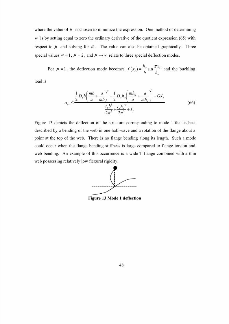
8/10/2019 Buckling of Bulb Flat Plates
http://slidepdf.com/reader/full/buckling-of-bulb-flat-plates 68/121
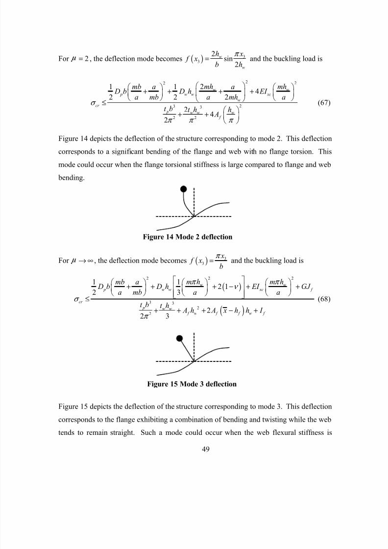
8/10/2019 Buckling of Bulb Flat Plates
http://slidepdf.com/reader/full/buckling-of-bulb-flat-plates 69/121
49
For 2= , the deflection mode becomes ( ) 33
2sin
2
w
w
h x f x
b h
π = and the buckling load is
2 22
23 3
2 2
21 14
2 2 2
24
2
w w
p w w xcw
cr
p w w w f
mh mhmb a a D b D h EI
a mb a mh a
t b t h h A
σ
π π π
+ + + +
≤
+ +
(67)
Figure 14 depicts the deflection of the structure corresponding to mode 2. This deflection
corresponds to a significant bending of the flange and web with no flange torsion. This
mode could occur when the flange torsional stiffness is large compared to flange and web
bending.
For → ∞ , the deflection mode becomes ( ) 33
x f x
b
π = and the buckling load is
( )
( )
2 22
3 32
2
1 1
2 12 3
22 3
w w
p w w xc f
cr
p w w f w f f w f
m h m hmb a
D b D h EI GJ a mb a a
t b t h A h A x h h I
π π
ν σ
π
+ + + − + +
≤
+ + + − +
(68)
Figure 15 depicts the deflection of the structure corresponding to mode 3. This deflection
corresponds to the flange exhibiting a combination of bending and twisting while the web
tends to remain straight. Such a mode could occur when the web flexural stiffness is
Figure 14 Mode 2 deflection
Figure 15 Mode 3 deflection

8/10/2019 Buckling of Bulb Flat Plates
http://slidepdf.com/reader/full/buckling-of-bulb-flat-plates 70/121
50
large compared to flange bending and torsion effects. This case is likely to occur when
the flange offers little or no additional stiffness to the plate structure compared to the
contribution of the web.
The value of can be interpreted to indicate the deflection behavior based on thethree special deflection modes.
Mode Flange bending Flange torsion Web bending
1 1 No Yes Yes
2 2 Yes No Yes
3 Yes Yes No∞

8/10/2019 Buckling of Bulb Flat Plates
http://slidepdf.com/reader/full/buckling-of-bulb-flat-plates 71/121
51
4. Buckling Expression Summary
The following summarizes the analytic expressions that predict the critical
buckling load and buckling behavior of a rectangular stiffened plate with a thin webbed
stiffener and solid flange treated as a beam. The general expression involves a constant
determined graphically. The value of indicates the deflection behavior.
General Buckling Load Expression ( )0 µ ≠
( )
( )
2 2 222
23 3 22
2 2
1 1 2 21 sin 4 1 sin sin cos
2 2 2 2
21 sin sin 2
2 2 2
w w p w w xc f
w
cr
p w w f w f f w
m h m hmb a a D b D h EI GJ
a mb a m h a
t b t h A h A x h h
µ π µ π µ π µ π π ν
µ π µ π µ π µ µ σ
µ µ π µ π µ
π π π µ π µ
+ + + − + − + +
≤
+ − + + −
2
sin cos cos f I π π π
π µ µ µ
+
Mode 1 Expression ( )1 µ =
22
3 3
2 2
1 1
2 2
2 2
w
p w w f
w
cr
p w w
f
mhmb a a D b D h GJ
a mb a mh
t b t h I
σ
π π
+ + + +
≤
+ +
Mode 2 Expression ( )2 µ =
2 22
23 3
2 2
21 14
2 2 2
2 42
w w p w w xc
w
cr
p w w w f
mh mhmb a a D b D h EI
a mb a mh a
t b t h h A
σ
π π π
+ + + +
≤
+ +
Mode 3 Expression ( ) µ → ∞
( )
( )
2 22
3 32
2
1 12 1
2 3
22 3
w w p w w xc f
cr
p w w f w f f w f
m h m hmb a D b D h EI GJ
a mb a a
t b t h A h A x h h I
π π ν
σ
π
+ + + − + +
≤
+ + + − +
The three special mode expressions provide initial approximations for the upper bound of
the buckling load value. Once the proper value of is estimated, the general expression
provides a value that is less than or equal to the lowest initial approximation.

8/10/2019 Buckling of Bulb Flat Plates
http://slidepdf.com/reader/full/buckling-of-bulb-flat-plates 72/121

8/10/2019 Buckling of Bulb Flat Plates
http://slidepdf.com/reader/full/buckling-of-bulb-flat-plates 73/121
53
The following figure shows the graph of the general expression for the buckling
load of the plate with a bulb-flat stiffener.
Figure 16 Maple 8 graph of the buckling load for the bulb-flat
stiffened plate example

8/10/2019 Buckling of Bulb Flat Plates
http://slidepdf.com/reader/full/buckling-of-bulb-flat-plates 74/121
54
Table 6 Results for the bulb-flat stiffened plate example
Descriptionσ ≤ Buckling Load
(psi)Remarks
Plate without stiffener 26773 (58)
Plate stiffened with no flange 27581(60)
3.02% above the no stiffenervalue.
Mode 1 44380 (66)
Mode 2 31262 (67)
Mode 3 31801 (68)
General Expression 27802
Graphically and (65).
3.02=
3.84% above the no stiffener
value.
0.80% above the no flange value.
Without stiffening, the plate is predicted to buckle at a load less than or equal to 26773
psi. When a flangeless web of height 3.3233 in.wh =
is added to the plate panel, the
plate buckles at a load of less than or equal to 27581 psi. Based on the value for , the
buckling behavior is predicted to exhibit flange bending and torsion with relatively little
web bending. The given flange cross-section adds relatively little additional stiffness
compared to the web stiffness.
E. FINITE ELEMENT ANALYSIS
Numerical and experimental investigations give insight about the behavior of
stiffened plates and serve as a basis of comparison to theoretical predictions. The results
of finite element analyses for several stiffened plate models using MSC Nastran
2001/Patran 2001-r3 software are compared to analytical predictions to establish a degree
of confirmation.

8/10/2019 Buckling of Bulb Flat Plates
http://slidepdf.com/reader/full/buckling-of-bulb-flat-plates 75/121
55
Several simply supported rectangular plate structures serve as finite element
models. Each plate structure has a plate panel of length a , width 2b , and thickness pt
such that pt b a< . The stiffener divides the width of the plate in halves. Each plate
panel half extends b units of length from the web to the simply supported edge. The
stiffener includes a thin web of length a , height wh , and thickness wt such that
w wt h a< . Four flange configurations are examined: no flange, bulb-flat flange,
circular flange, and T-flange. Each stiffened plate structure is subjected to axial
compression due to a uniform normal stress σ , which increases to the buckling load.
The boundary of the plate panel is simply supported at all edges. The stiffener is simply
supported at the ends.
The derived analytical expressions in the previous section were modeled
assuming a plate panel of width b . This coincides with the analysis of a single plate unit
containing a single longitudinal stiffener that would be part of a larger plate structure
where b units of length separate each stiffener. In this discussion, the plate structure is
modeled with width 2b , as shown in Figure 17. The boundary conditions are now
( ) ( )
( ) ( )
1 1
22 1 22 1
, , 0
, , 0
W x b W x b
W x b W x b
− = =
− = =
Figure 17 Stiffened plate pre-buckling and buckling mode
2b
2
3 x

8/10/2019 Buckling of Bulb Flat Plates
http://slidepdf.com/reader/full/buckling-of-bulb-flat-plates 76/121

8/10/2019 Buckling of Bulb Flat Plates
http://slidepdf.com/reader/full/buckling-of-bulb-flat-plates 77/121
57
The flange parameters used for area levels 3 and 4 are not from the data in Table 2 or
Table 3. Analyses of these bulb-flat flanges provide an assessment of the prediction
accuracy for non-standard parameters. The four flange configurations examined are
Flange Configuration Label Description1 N/A No flange
2 b Bulb-flat
3 c Circular
4 t T-flange
For the stiffened plate structure without a flange, the web deflection mode is of the form
(59) and the predicted buckling load is determined by
( )
22
3 3
2
1
2 13
3
w
p w w
cr
p w w
m hmb a
D b D ha mb a
t b t h
π
ν σ
π
+ + + −
≤
+
Otherwise the stiffener has a flange and the web deflection is of the form (64) with the
predicted buckling load determined by
( )
( )
2 2 222
23 3 22
2 2
1 2 21 sin 4 1 sin sin cos
2 2 2
21 sin sin 2 si
22
w w p w w xc f
w
cr
p w w
f w f f w
m h m hmb a a D b D h EI GJ
a mb a m h a
t b t h A h A x h h
µ π µ π µ π µ π π ν
µ π µ π µ π µ µ σ
µ µ π µ π µ
π µ π µ π π π
+ + + − + − + +
≤
+ − + + −
2
n cos cos f
I π π π
µ µ µ
+

8/10/2019 Buckling of Bulb Flat Plates
http://slidepdf.com/reader/full/buckling-of-bulb-flat-plates 78/121
58
Using the values from the previous two pages and converting the units from
millimeter to inches provides the parameters for the stiffened plate models. The
following tables present the converted parameter values. The data tables in Appendix C
for the stiffened plate finite element models are in inch units (See Table 40 - Table 55).
Converting the results back into millimeter units may yield values that differ slightly
from those presented in previous sections.
Table 7 Summary of stiffened plate model 1 parameters
Configuration Flange Parameters and Properties Web Parameters
Model 1 20.5202 in f A = 3.3233 in
0.2362 in
w
w
h
t
=
=
No flange
See Table 40
No flange area Same as above
Bulb-flat (b)See Table 427
1
0.2362 in
0.6693 in
0.1969 in
(1/10) 0.0236 in
/ 6 radians
0.8106 in
w
bf
w
f
t
t
r
r t
h
α π
=
=
=
= =
=
=
4.1339 in sh =
Circular (c)
See Table 48
radius 0.4069 in
0.8138 in f h
=
=
4.1371 in sh =
T-flange (t)See Table 54
width 2.2020 inthickness 0.2362 in
=
= 3.5595 in sh =
7 The parameters for this model configuration were used in a grillage tested by the Naval SurfaceWarfare Center. The flange and web parameters are the same as used in the example on page 52.

8/10/2019 Buckling of Bulb Flat Plates
http://slidepdf.com/reader/full/buckling-of-bulb-flat-plates 79/121
59
Table 8 Summary of stiffened plate model 2 parameters
Configuration Flange Parameters Web Parameters
Model 2 20.6226 in f A = 3.3233 in
0.2362 in
w
w
h
t
=
=
No flangeSee Table 40
No flange area Same as above
Bulb-flat (b)
See Table 43
1
0.2362 in
0.7874 in
0.1969 in
(1/10) 0.0236 in
/ 6 radians
0.8788 in
w
bf
w
f
t
t
r
r t
h
α π
=
=
=
= =
=
=
4.2021 in sh =
Circular (c)
See Table 49
radius 0.4452 in
0.8904 in f h
=
=
4.2137 in sh =
T-flange (t)See Table 54
width 2.6357 in
thickness 0.2362 in
=
=
3.5595 in sh =
Table 9 Summary of stiffened plate model 3 parameters
Configuration Flange Parameters Web Parameters
Model 3 20.8113 in f A = 3.3233 in
0.2362 in
w
w
h
t
=
=
No flange
See Table 40
No flange area Same as above
Bulb-flat (b)See Table 44
1
0.2362 in
0.9843 in
0.1969 in
(1/10) 0.0236 in
/ 6 radians
0.9924 in
w
bf
w
f
t
t
r
r t
h
α π
=
=
=
= =
=
=
4.3157 in sh =
Circular (c)
See Table 50
radius 0.5082 in
1.0163 in f h
=
=
4.3396 in sh =
T-flange (t)
See Table 54width 3.4343 in 87.23 mm
thickness 0.2362 in 6 mm
= =
= =
3.5595 in sh =

8/10/2019 Buckling of Bulb Flat Plates
http://slidepdf.com/reader/full/buckling-of-bulb-flat-plates 80/121
60
Table 10 Summary of stiffened plate model 4 parameters
Configuration Flange Parameters Web Parameters
Model 4 Same as model 1 3.9138 in
0.2362 in
w
w
h
t
=
=
No flangeSee Table 41
No flange area Same as above
Bulb-flat (b)
See Table 45
Same as model 1b 4.7244 in sh =
Circular (c)
See Table 51
Same as model 1c 4.7276 in sh =
T-flange (t)See Table 55
Same as model 1t 4.1501 in sh =
Table 11 Summary of stiffened plate model 5 parameters
Configuration Flange Parameters Web ParametersModel 5 Same as model 2 3.9138 in
0.2362 in
w
w
h
t
=
=
No flange
See Table 41
No flange area Same as above
Bulb-flat (b)
See Table 46
Same as model 2b 4.7926 in sh =
Circular (c)
See Table 52
Same as model 2c 4.8042 in sh =
T-flange (t)
See Table 55
Same as model 2t 4.1501 in sh =
Table 12 Summary of stiffened plate model 6 parameters
Configuration Flange Parameters Web Parameters
Model 6 Same as model 3 3.9138 in
0.2362 in
w
w
h
t
=
=
No flange
See Table 41
No flange area Same as above
Bulb-flat (b)
See Table 47
Same as model 3b 4.9063 in sh =
Circular (c)See Table 53
Same as model 3c 4.9301 in sh =
T-flange (t)
See Table 55
Same as model 3t 4.1501 in sh =

8/10/2019 Buckling of Bulb Flat Plates
http://slidepdf.com/reader/full/buckling-of-bulb-flat-plates 81/121
61
The following tables present intermediate results for the stiffened plate models.
Table 13 Model 1 intermediate results
Result Bulb-flat Circular T-flange
f h (in) 0.8106 0.8138 0.2362
x (in) 0.3214 0.4069 0.1181
y (in) 0.3694 0.4069 1.1010
c I (in4) 0.0526 0.0431 0.2126
xc I (in4) 0.0309 0.0215 0.2102
J (in4) 0.0321 0.0431 0.0090
I (in4) 0.2100 0.1292 0.2199
xc EI (lb-in2) 926071 645945 6305666
f GJ (lb-in2) 370796 496881 104091
Mode 1 (psi) 35599 36107 34548
Mode 2 (psi) 29053 28905 31902
Mode 3 (psi) 29356 29455 35105
Table 14 Model 2 intermediate results
Result Bulb-flat Circular T-flange
f h (in) 0.8788 0.8904 0.2362
(in) 0.3413 0.4452 0.1181
y (in) 0.4145 0.4452 1.3179c I (in
4) 0.0773 0.0617 0.3633
xc I (in4) 0.0473 0.0308 0.3604
J (in4) 0.0449 0.0617 0.0109
I (in4) 0.3119 0.1851 0.3720
xc EI (lb-in2) 1417646 92544310813397
f GJ (lb-in2) 517932 711879 126078
Mode 1 (psi) 36164 36946 34614
Mode 2 (psi) 29261 29001 34229
Mode 3 (psi) 30474 30553 40794

8/10/2019 Buckling of Bulb Flat Plates
http://slidepdf.com/reader/full/buckling-of-bulb-flat-plates 82/121
62
Table 15 Model 3 intermediate results
Result Bulb-flat Circular T-flange
f h (in) 0.9924 1.0163 0.2362
(in) 0.3753 0.5082 0.1181
y (in) 0.4886 0.5082 1.7172
c I (in4) 0.1361 0.1047 0.8011
xc I (in4) 0.0872 0.0524 0.7974
f J (in4) 0.0735 0.1047 0.0144
f I (in4) 0.5564 0.3142 0.8125
xc EI (lb-in2) 2617311 157119723921250
f GJ (lb-in2) 848126 1208613 166564
Mode 1 (psi) 37428 38882 34713
Mode 2 (psi) 29798 29247 41024Mode 3 (psi) 33128 33117 57198
Table 16 Model 4 intermediate results
Result Bulb-flat Circular T-flange
f h (in) 0.8106 0.8138 0.2362
x (in) 0.3214 0.4069 0.1181
y (in) 0.3694 0.4069 1.1010
c I (in4) 0.0526 0.0431 0.2126
xc I (in4) 0.0309 0.0215 0.2102
J (in4) 0.0321 0.0431 0.0090
I (in4) 0.2100 0.1292 0.2199
xc EI (lb-in2) 926071 645945 6305666
f GJ (lb-in2) 370796 496881 104091
Mode 1 (psi) 34602 35109 33551
Mode 2 (psi) 28862 28657 32783
Mode 3 (psi) 29541 29495 37813

8/10/2019 Buckling of Bulb Flat Plates
http://slidepdf.com/reader/full/buckling-of-bulb-flat-plates 83/121
63
Table 17 Model 5 intermediate results
Result Bulb-flat Circular T-flange
f h (in) 0.8788 0.8904 0.2362
(in) 0.3413 0.4452 0.1181
y (in) 0.4145 0.4452 1.3179
c I (in4) 0.0773 0.0617 0.3633
xc I (in4) 0.0473 0.0308 0.3604
J (in4) 0.0449 0.0617 0.0109
I (in4) 0.3119 0.1851 0.3720
xc EI (lb-in2) 1417646 92544310813397
f GJ (lb-in2) 517932 711879 126078
Mode 1 (psi) 35166 35947 33618
Mode 2 (psi) 29148 28791 35980Mode 3 (psi) 30844 30672 45530
Table 18 Model 6 intermediate results
Result Bulb-flat Circular T-flange
f h (in) 0.9924 1.0163 0.2362
(in) 0.3753 0.5082 0.1181
y (in) 0.4886 0.5082 1.7172
c I (in4) 0.1361 0.1047 0.8011
xc I (in4) 0.0872 0.0524 0.7974
J (in4) 0.0735 0.1047 0.0144
I (in4) 0.5564 0.3142 0.8125
xc EI (lb-in2) 2617311 157119723921250
f GJ (lb-in2) 848126 1208613 166564
Mode 1 (psi) 36430 37882 33718
Mode 2 (psi) 29886 29129 45307
Mode 3 (psi) 33964 33430 67754

8/10/2019 Buckling of Bulb Flat Plates
http://slidepdf.com/reader/full/buckling-of-bulb-flat-plates 84/121
64
The following pictures show the deflection of the plate and web at the onset of
buckling for Model 1b. The plate and web panels buckle in 4 half waves along the
longitudinal axis. The bulb-flat flange is not visible, but its properties exist in the curve
that defines the top of the web.
Figure 18 MSC Nastran picture 1 for stiffened plate Model 1b
Figure 19 MSC Nastran picture 2 for stiffened plate Model 1b

8/10/2019 Buckling of Bulb Flat Plates
http://slidepdf.com/reader/full/buckling-of-bulb-flat-plates 85/121
65
Figure 20 Maple 8 graph 1 of the buckling loads for Model 1
mtmily
si m
L n t L n L t y
mu
Bulb tlal
Circular

8/10/2019 Buckling of Bulb Flat Plates
http://slidepdf.com/reader/full/buckling-of-bulb-flat-plates 86/121
66
Figure 21 Maple 8 graph 2 of the buckling loads for Model 1
si^ma
36000
34IIIH
32000
^
30000
1.5 2 5
mu
Btilb flal
Circular
T llange

8/10/2019 Buckling of Bulb Flat Plates
http://slidepdf.com/reader/full/buckling-of-bulb-flat-plates 87/121
67
Figure 22 Maple 8 graph of the buckling load for the bulb-flat
configuration of Model 1

8/10/2019 Buckling of Bulb Flat Plates
http://slidepdf.com/reader/full/buckling-of-bulb-flat-plates 88/121
68
The pictures below show the difference in the buckling behavior between models
2b and 3b. In each picture, the top of the web has the beam characteristics of a bulb-flat
flange. The flange in the left picture has an area property of 0.6226 in2. The flange in the
right picture has an area property of 0.8113 in2. These properties are not visible in the
pictures, but exist in the curve that defines the top of each web. The web height in both
pictures is 3.3233 in. From Table 20, the values for the left and right pictures are 2.57
and 2.25 respectively. This indicates there is more lateral bending of the Model 2b flange
at the onset of buckling, which agrees with the pictures shown above.
Figure 23 MSC Nastran pictures showing the buckling behavior of the webs
with bulb-flat flanges for Models 2b (left) and 3b (right)

8/10/2019 Buckling of Bulb Flat Plates
http://slidepdf.com/reader/full/buckling-of-bulb-flat-plates 89/121
69
The pictures below show the difference in the buckling behavior between models
4b, 5b, and 6b from left to right respectively. The flanges have area properties of 0.5202
in2, 0.6226 in
2, and 0.8113 in
2, respectively. The web height in the pictures is 3.9138 in.
From Table 20, the values are 2.68, 2.40, and 2.11, respectively.
The pictures above show the difference in the buckling behavior between models 4t and
6t. The flanges have area properties of 0.5202 in2
and 0.8113 in2, respectively. The web
height in the pictures is 3.9138 in. From Table 22, the values are 1.51 and 1.08,
respectively.
Figure 24 MSC Nastran pictures showing the buckling behavior of
the webs with bulb-flat flanges for Models 4b (left), 5b (center), and 6b
(right)
Figure 25 MSC Nastran pictures showing
the buckling behavior of the webs with T-flanges
for Models 4t (left) and 6t (right)

8/10/2019 Buckling of Bulb Flat Plates
http://slidepdf.com/reader/full/buckling-of-bulb-flat-plates 90/121
70
The following tables show the formula predictions and finite element results.
Table 19 No flange FE results
Model# FE Results (psi) Analytic Prediction (psi) Percent Change
1-3 26928 27181 0.94%
4-6 26892 27138 0.91%
Table 20 Bulb-flat FE results
Model# FE Results (psi) Analytic Prediction (psi) Percent Change
1b 27672 28397 2.86 2.62%
2b 27877 28824 2.57 3.40%
3b 28203 29642 2.25 5.10%
4b 27663 28425 2.68 2.75%
5b 27881 28908 2.40 3.68%
6b 28217 29852 2.11 5.79%
Table 21 Circular FE results
Model# FE Results (psi) Analytic Prediction (psi) Percent Change
1c 27558 28246 2.78 2.50%
2c 27703 28524 2.54 2.96%
3c 27936 29000 2.29 3.81%
4c 27498 28178 2.65 2.47%
5c 27654 28469 2.44 2.95%
6c 27907 28996 2.21 3.90%
Table 22 T-flange FE results
Model# FE Results (psi) Analytic Prediction (psi) Percent Change
1t 28767 31864 1.85 10.77%
2t 29030 33200 1.45 14.36%
3t 29291 34220 1.15 16.83%
4t 28739 32146 1.51 11.85%
5t 28933 32945 1.23 13.87%
6t 29119 33460 1.08 14.91%

8/10/2019 Buckling of Bulb Flat Plates
http://slidepdf.com/reader/full/buckling-of-bulb-flat-plates 91/121
71
Table 19 compares the results for the stiffened plates without flanges. The
formula values nearly agree with the finite element results. Table 20 compares the bulb-
flat configurations for each model. The formula values are less than 6% above the finite
element results. Examination of the values indicates that the buckling behavior of the
stiffened plates tend to have significant bending of the flange and web with a degree of
flange torsion. This type of buckling behavior can be seen in the Nastran pictures on the
previous pages. As the flange areas increase between models 1, 2, and 3, and also
between models 4, 5, and 6, the values tend to approach the value 2, indicating
perhaps an increasing torsional rigidity effect. The buckling loads tend to increase as the
flange area increases, as expected. Overall, the results indicate that at the onset of
buckling, the bulb-flat stiffened plate structures deflect with a combination of flange
bending and torsion along with web bending. Table 21 compares the circular flange
configurations, which appear to buckle at a slightly lower value than the bulb-flat
configurations, but behave similar to them at the onset of buckling. Table 22 compares
the T-flange configurations. From the finite element results, the buckling load of a plate
with a bulb-flat stiffener is 3% - 4% less than that of a plate with a T-flange stiffener with
the same cross-sectional area. Based on the values for the T-flange configuration,
bending of the flange tends to decrease as the cross-sectional area increases. The
difference in the formula values from the finite element values could be due to
fundamental assumption (ix). Though the T-flange is solid, treating the flange as a thin
web plate strip instead of a beam may achieve more accurate predictions. This may
explain the increase in error for the bulb-flat and T-flange cases as the area increases due
to flange widening. The increasing error is less pronounced for the circular flange
models.

8/10/2019 Buckling of Bulb Flat Plates
http://slidepdf.com/reader/full/buckling-of-bulb-flat-plates 92/121
72
THIS PAGE INTENTIONALLY LEFT BLANK

8/10/2019 Buckling of Bulb Flat Plates
http://slidepdf.com/reader/full/buckling-of-bulb-flat-plates 93/121
73
IV. FINDINGS AND CONCLUSIONS
The following summarizes the major findings and conclusions of this work. Each
major finding or conclusion is stated followed by explanatory comments.
• Determined cross-sectional boundary equations for the bulb-flat flange cross-
section.
In order to conduct an accurate analysis of the bulb-flat cross-section, it is
necessary to determine equations that define or at least approximate the boundary that is a
closed bounded plane region. The equation that defines the boundary of a simple
geometric cross-section like a circle or ellipse is well known. The boundary equation for
uncommon and asymmetric cross-sections is often very difficult to define. As a result of
this study, functions exist that define the boundary of the bulb-flat flange cross-section.
• Derived planar property value expressions.
Determining the critical buckling load of a stiffened plate structure requires
knowledge of several planar property values of the plate’s cross-section. Based on the
boundary equations and the application of multivariable calculus, the double integral
provides expressions for calculating the various planar properties of the bulb-flat flange
cross-section. Though the integral expressions are complicated, they could be simplified
by assigning fixed values to certain variables.
• Determined an approximate torsional constant expression that is more
accurate than idealizing.
The Saint-Venant torsional constant is one of the key property values involved in
the analysis of stiffened plate structures. Due to the uncommon shape and asymmetrical
property of the bulb-flat cross-section, determining the exact expression for the Saint-
Venant torsional constant is difficult and does not exist in published literature. As a
result of this study, an approximate expression exists for the Saint-Venant torsional
constant of a specified class of bulb-flat cross-sections. The approximate expression is a
one-term function relating the cross-sectional area to the polar moment of inertia. The

8/10/2019 Buckling of Bulb Flat Plates
http://slidepdf.com/reader/full/buckling-of-bulb-flat-plates 94/121
74
approximate expression is more accurate than the estimate obtained by idealizing the
cross-section as an angle flange.
• Demonstrated that the torsional property of the bulb-flat stiffener is better than
previously understood. The torque-carrying capacity of a bulb-flat stiffener
(possessing no structural flaws) is greater than that of an area-equivalent angle
stiffener.
In previous investigations the torsional nature of the bulb-flat stiffener was
idealized as an angle flange stiffener. That is, the bulb-flat flange cross-section was
treated like a rectangular cross-section in regards to the torsional and warping properties.
Such treatment imputed error in the calculation of the bulb-flat stiffener’s torsional
rigidity resulting in conservative estimates. Finite element analysis indicates that the
torque-carrying capacity of a bulb-flat stiffener (possessing no structural flaws) is greater
than that of an area-equivalent angle stiffener.
• Derived a general expression to predict the buckling load due to the stiffener
tripping of a simply supported rectangular stiffened plate subjected to axial
compression. In the investigation, the predicted value is less than 6% higher
than the finite element result.
Understanding the elastic stability of stiffened plate structures is important to the
analyst, designer, and educator involved in the analysis and design of structures. Use of
the energy method provides a technique to derive a general expression for the buckling
load due to the stiffener tripping of a simply supported rectangular stiffened plate
subjected to axial compression. As a result of this study, a useful analytic expression
exists that allows the user to predict the critical buckling load and the buckling behavior
of a stiffened plate at the onset of stiffener tripping. The onset of stiffener tripping
negates the stiffener’s support to the plate panel and leads to eventual collapse of the
structure. The general expression involves a constant called that is determined
graphically. The value of can be interpreted to indicate the deflection behavior based
on three special deflection modes.

8/10/2019 Buckling of Bulb Flat Plates
http://slidepdf.com/reader/full/buckling-of-bulb-flat-plates 95/121
75
Mode Flange bending Flange torsion Web bending
1 1 No Yes Yes
2 2 Yes No Yes
3 Yes Yes No∞
Finite element analyses of several stiffened plate models is presented to validate
the analytic expressions and assess the sensitivity of the formulas to factor variability.
Knowledge of MSC Nastran/Patran software and finite element principles along with the
Maple 8 computer environment was essential for this investigation.
• Demonstrated that the buckling behavior of the bulb-flat stiffened plate is
markedly unlike that of the T-flange configuration. The bulb-flat tends to
buckle more laterally and have a lower buckling load value than an area-
equivalent T-flange stiffened plate.
The bulb-flat stiffened plate tends to buckle in a Mode 2 fashion, while the T-
flange stiffened plate tends to buckle in a Mode 1 fashion. Hence, the torsional superior
bulb-flat tends to bend laterally at the onset of stiffener tripping, while the flexural
superior T-flange tends to twist axially at the onset of stiffener tripping.
As a result of this investigation, several essential future research directions exist.
Future research should include:
• Investigating methods to determine the value by other than graphical
means.
• Investigating the use of conformal mapping to determine the exact expression
for the bulb-flat torsional constant.
• Investigating solutions to the torsion problem for asymmetric cross-sections.
• Conducting investigations of other flange cross-sections, multiple stiffener
configurations, and grillages.
• Conducting further investigations of the T flange by treating the flange as a
thin web plate strip instead of a beam. This treatment may achieve more
accurate predictions for the T-flange buckling loads.
• Developing algorithms that increase efficiency in stiffened plate analysis and
design.

8/10/2019 Buckling of Bulb Flat Plates
http://slidepdf.com/reader/full/buckling-of-bulb-flat-plates 96/121
76
THIS PAGE INTENTIONALLY LEFT BLANK

8/10/2019 Buckling of Bulb Flat Plates
http://slidepdf.com/reader/full/buckling-of-bulb-flat-plates 97/121
77
APPENDIX A. THE BULB-FLAT FLANGE HEIGHT FORMULA
This appendix presents the derivation of the formula for the height of the bulb-flat
flange cross-section. Maple 8 computer environment software was used to derive some
of the formula final forms. Five independent variables uniquely determine a specific
bulb-flat cross-section.
wt Thickness of the web (length)
bf t Thickness of the flange bulb (length)
r Radius of curvature of flange bulb and neck curve (length)
1r Radius of curvature of the cross-section corner (length)
α Slope angle of the flange neck (radians)
It will be shown that only three of the independent variables, , andbf t r α , determine the
height of the flange. Throughout this discussion, it is assumed 0 / 2α π < < . The
following figures show a model of the bulb-flat flange oriented horizontally with the bulb
extended to one side of the web.

8/10/2019 Buckling of Bulb Flat Plates
http://slidepdf.com/reader/full/buckling-of-bulb-flat-plates 98/121
78
Figure 26 Bulb-flat flange geometry
Figure 27 MSC Patran Bulb-flat flange boundary
points for cross-section properties
bf t
wt
f h
α
1r
r
r
y
x

8/10/2019 Buckling of Bulb Flat Plates
http://slidepdf.com/reader/full/buckling-of-bulb-flat-plates 99/121
79
The three circles in Figure 26 show the radii of curvature at the corners of the flange.
The height of the flange, denoted f h , is the distance from the left boundary 0 x = to the
right boundary f h= . Consider the line segment tangent to the two circles of radius r .
In Figure 27, the line segment connects point 7 ( )7 7, y and point 8 ( )8 8, y where
7
7
is to be determined
sinw
x
y t r r α = + − (69)
and
8
8
cos
sinw bf
x r r
y t t r r
α
α
= +
= + − + (70)
The flange height can be expressed simply as
7 cos f h x r α = + (71)
Once 7 is determined, f h is determined from (71). The slope of line segment is
( )7 87 7 8 8
7 8
cot tan y y y
slope x y y x x x x
α α −∆
= = = − ⇒ = − − +∆ −
(72)
From (69) and (70)
( ) ( )( )
7 8 sin sin2 1 sin
w w bf
bf
y y t r r t t r r t r
α α α
− = + − − + − +
= − + −
(73)
From (72) and (73)
7 8 tan 2 tan 2 sec 2 cosbf x x t r r r α α α α − = − + − (74)
and
7 tan 2 tan 2 sec cosbf x t r r r r α α α α = + − + − (75)
Substituting (75) into (71) yields the following formula.
( )tan 1 2 tan 2sec f bf h t r α α α = + − + (76)

8/10/2019 Buckling of Bulb Flat Plates
http://slidepdf.com/reader/full/buckling-of-bulb-flat-plates 100/121
80
THIS PAGE INTENTIONALLY LEFT BLANK

8/10/2019 Buckling of Bulb Flat Plates
http://slidepdf.com/reader/full/buckling-of-bulb-flat-plates 101/121
81
APPENDIX B. THE PLANAR PROPERTY FORMULAS
The purpose of this appendix is to present the derivation of the planar property
formulas for the bulb-flat flange. It is assumed 0 / 2α π < < throughout the discussion.
Let the closed bounded plane region R be defined by 0 f h≤ ≤ ,
( ) ( ) g x y f x≤ ≤ , with ( ) f x and ( ) g x on 0, x h ∈ , such that
( )
( ) ( ) ( )
( )
( ) ( ) ( )
22
1
2
22
3
, 0
, cos
,
cos
cos
cos
w bf
f
w f f f
f x r x r x
f x mx b r r x h
f x r x h x
t t r r r
f x r
t r h r h
α
α
α
α
= + − − ≤ <
= + + ≤ <
= − − − ≤ ≤
+ − +
= −
+ −
(77)
and
( ) ( ) ( )
( )
22
1 1 1 1 1
2 1
, 0
0, f
g x r r x r x r g x
g x r x h
= − − − ≤ <
= = ≤ ≤
(78)
where
( )
( )
cot
cot csc 1
tan 1 2 tan 2sec
w bf
f bf
m
b t t r
h t r
α
α α
α α α
= −
= + + + −
= + − +
(79)
By the theorem of integrability of a piecewise function8, since f and g are piecewise
defined functions on the same closed interval, then f and g are integrable on the same
closed interval. The planar property formulas can be determined from the following
expression where ,m n are nonnegative integers.
( )
( )
( ) ( ){ }1 1
0 0
1
1
f f h h f xn nm n m n m
R g x
x y dA x y dydx x f x g x dxn
+ +
= = − +
∫∫ ∫ ∫ ∫
8 Ross, K.A., Elementary Analysis: The Theory of Calculus, Springer, New York, pp. 258-259.

8/10/2019 Buckling of Bulb Flat Plates
http://slidepdf.com/reader/full/buckling-of-bulb-flat-plates 102/121
82
( ) ( )
( )
( ) ( )
( ) ( )
21
2
cos1
cos
01
2
012
1
2
1sin cos cos
1
1
cot cot csc1
1sin cos cos
1
11 sin 1 cos cos
1
f
nmm n
w bf
R
h r n
m
w bf r r
m n
f w
m nm n
x y dA r r t t r r r d n
x t t r r r dxn
h r t r r r d n
r d n
π α
π
α
α
π α
π
θ θ θ θ
α α α
θ θ θ θ
θ θ θ θ
−
+
−
−
+
+
+
−
++ +
−
= + + − ++
+ − + + + + −+
+ + + −+
− + −+
∫∫ ∫
∫
∫
∫
where
( )tan 1 2 tan 2sec
0 , , 02 2 2
f bf
f
h t r
h
α α α
π π π α θ
= + − +
< < − ≤ ≤ ≤ ≤
By definition, the area of the closed bounded plane region R is the value of the integral
( )
( )
( ) ( )0 0
0 0
Area
f f h h f x
R R g x
x y dA dA dy dx f x g x dx= = = = −∫∫ ∫∫ ∫ ∫ ∫
Hence,
( ) ( ) ( ) ( ) ( )1
1
coscos
1 2 3 1 2
0 cos cos 0
f f f
f
h r h hr r r
R r r h r r
dA f x dx f x dx f x dx g x dx g x dx
α α
α α
−+
+ −
= + + − −∫∫ ∫ ∫ ∫ ∫ ∫
( ) ( )
( ) ( )
cos2
cos
2
0 0
2
1
2 2
cos cos cot cot csc
cos cos 1 cos cos
f h r
w bf w bf
R r r
w
dA t t r r r d x t t r r r dx
t r r r d r d
π α α
π α
π π α
θ θ θ α α α
θ θ θ θ θ θ
− −
+−
− −
= + − + + − + + + + −
+ + − − −
∫∫ ∫ ∫
∫ ∫
Integrating and collecting terms yields the area of the bulb-flat flange:
( ) ( ) ( )2 2
1
2
1 1 2 tan 2 sec 1 tan sec4
1tan tan
2
f w bf
bf w bf
A r r rt rt
t t t
π α α α α
α α
= − − + + − + + − +
+ +
(80)

8/10/2019 Buckling of Bulb Flat Plates
http://slidepdf.com/reader/full/buckling-of-bulb-flat-plates 103/121
83
Other planar property formulas are determined in similar fashion and are
summarized below (algebraic expansion omitted).
( )
( )
( ) ( )
0 1
22
2
cos2
cos
0 02 23
1
2 2
1cos cos
2
1cot cot csc
2
1 1cos cos 1 cos cos
2 2
f
x
R R
w bf
h r
w bf
r r
w
M x y dA y dA
t t r r r d
x t t r r r dx
t r r r d r d
π α
π
α
α
π π α
θ θ θ
α α α
θ θ θ θ θ θ
−
−
−
+
− −
= =
= + − +
+ − + + + + −
+ + − − −
∫∫ ∫∫
∫
∫
∫ ∫
(81)
( ) ( )
( )
( )( ) ( )( )
1 0
2
2
cos
cos
0 0
3
1
2 2
sin cos cos
cot cot csc
sin cos cos 1 sin 1 cos cos
f
y
R R
w bf
h r
w bf
r r
f w
M x y dA x dA
r r t t r r r d
x x t t r r r dx
h r t r r r d r d
π α
π
α
α
π π α
θ θ θ θ
α α α
θ θ θ θ θ θ θ θ
−
−
−
+
− −
= =
= + + − +
+ − + + + + −
+ + + − − + −
∫∫ ∫∫
∫
∫
∫ ∫
(82)
y
f
x A
= (83)
x
f
y A
= (84)

8/10/2019 Buckling of Bulb Flat Plates
http://slidepdf.com/reader/full/buckling-of-bulb-flat-plates 104/121

8/10/2019 Buckling of Bulb Flat Plates
http://slidepdf.com/reader/full/buckling-of-bulb-flat-plates 105/121
85
2
yc yy f I I A x= − (89)
xyc xy f I I A x y= − (90)
c xc yc
I I I = + (91)

8/10/2019 Buckling of Bulb Flat Plates
http://slidepdf.com/reader/full/buckling-of-bulb-flat-plates 106/121
86
THIS PAGE INTENTIONALLY LEFT BLANK

8/10/2019 Buckling of Bulb Flat Plates
http://slidepdf.com/reader/full/buckling-of-bulb-flat-plates 107/121
87
APPENDIX C. DATA TABLES
This appendix presents flange, stiffener, and plate data tables used to model the
cross-sections for finite element analysis. When creating a finite element model of a
structure, a matrix represents the structure. The information in the left portion of each
table list parameters or references related to the set of points contained in the right
portion of the table.
1. DATA FOR BULB-FLAT FLANGE CROSS-SECTION
See Figure 3 and Figure 5.
Table 23 Data for Flange Model 1 in Table 2 (units in mm)
1
6
17
5
(1/10) =6/10
/ 6
20.59
335.59
w
bf
w
f
f
t
t
r
r t
h
A
α π
=
=
=
=
=
=
=
[0.0000 0.6000 0.0000][0.1757 0.1757 0.0000][0.6000 0.0000
0.0000][20.5885 0.0000 0.0000][20.5885 6.0000 0.0000][18.0885
6.6699 0.0000][16.2583 8.5000 0.0000][9.3301 20.50000.0000][5.0000 23.0000 0.0000][0.0000 18.0000 0.0000]
Table 24 Data for Flange Model 3 in Table 2 (units in mm)
1
8
17
5
(1/10) =8/10
/ 6
20.59
376.71
w
bf
w
f
f
t
t
r
r t
h
A
α π
=
=
=
=
=
=
=
[0.0000 0.8000 0.0000][0.2343 0.2343 0.0000][0.8000 0.00000.0000][20.5885 0.0000 0.0000][20.5885 8.0000 0.0000][18.0885
8.6699 0.0000][16.2583 10.5000 0.0000][9.3301 22.5000
0.0000][5.0000 25.0000 0.0000][0.0000 20.0000 0.0000]

8/10/2019 Buckling of Bulb Flat Plates
http://slidepdf.com/reader/full/buckling-of-bulb-flat-plates 108/121

8/10/2019 Buckling of Bulb Flat Plates
http://slidepdf.com/reader/full/buckling-of-bulb-flat-plates 109/121
89
Table 28 Data for Flange Model 10 in Table 2 (units in mm)
1
9
22
6
(1/10) =9/10
/ 6
25.63
570.70
w
bf
w
f
f
t
t
r
r t
h
A
α π
=
=
=
=
=
=
=
[0.0000 0.9000 0.0000][0.2636 0.2636 0.0000][0.9000 0.0000
0.0000][25.6299 0.0000 0.0000][25.6299 9.0000
0.0000][22.6299 9.8038 0.0000][20.4338 12.0000
0.0000][11.1962 28.0000 0.0000][6.0000 31.0000
0.0000][0.0000 25.0000 0.0000]
Table 29 Data for Flange Model 12 in Table 2 (units in mm)
1
8
25
7
(1/10) =8/10
/ 6
29.52
681.94
w
bf
w
f
f
t
t
r
r t
h
A
α π
=
=
=
=
=
=
=
[0.0000 0.8000 0.0000][0.2343 0.2343 0.0000][0.8000 0.0000
0.0000][29.5167 0.0000 0.0000][29.5167 8.0000
0.0000][26.0167 8.9378 0.0000][23.4545 11.50000.0000][13.0622 29.5000 0.0000][7.0000 33.0000
0.0000][0.0000 26.0000 0.0000]
Table 30 Data for Flange Model 14 in Table 2 (units in mm)
1
1025
7
(1/10) =10/10=1
/ 6
29.52
740.89
w
bf
w
f
f
t t
r
r t
h
A
α π
=
=
=
=
=
=
=
[0.0000 1.0000 0.0000][0.2929 0.2929 0.0000][1.0000 0.00000.0000][29.5167 0.0000 0.0000][29.5167 10.0000
0.0000][26.0167 10.9378 0.0000][23.4545 13.50000.0000][13.0622 31.5000 0.0000][7.0000 35.0000
0.0000][0.0000 28.0000 0.0000]

8/10/2019 Buckling of Bulb Flat Plates
http://slidepdf.com/reader/full/buckling-of-bulb-flat-plates 110/121
90
2. DATA FOR THE BULB-FLAT STIFFENER CROSS-SECTION
See Figure 1, Figure 7, and Figure 8.
Table 31 Data for first stiffener in Table 5 (units in mm)
1
120
20.59
99.41
6
17
5
(1/10) =6/10
/ 6
s
f
w
w
bf
w
h
h
h
t
t
r
r t
α π
=
=
=
=
=
=
=
=
[0.0000 0.0000 0.0000][6.0000 0.0000 0.0000][6.0000 99.41150.0000][6.6699 101.9115 0.0000][8.5000 103.74170.0000][20.5000 110.6699 0.0000][23.0000 115.0000
0.0000][18.0000 120.0000 0.0000][0.6000 120.0000
0.0000][0.1757 119.8243 0.0000][0.0000 119.4000 0.0000]
Table 32 Data for second stiffener in Table 5 (units in mm)
1
120
20.59
99.41
8
17
5
(1/10) =8/10
/ 6
s
f
w
w
bf
w
h
h
h
t
t
r
r t
α π
=
=
=
=
=
=
=
=
[0.0000 0.0000 0.0000][8.0000 0.0000 0.0000][8.0000 99.4115
0.0000][8.6699 101.9115 0.0000][10.5000 103.74170.0000][22.5000 110.6699 0.0000][25.0000 115.0000
0.0000][20.0000 120.0000 0.0000][0.8000 120.0000
0.0000][0.2343 119.7657 0.0000][0.0000 119.2000 0.0000]

8/10/2019 Buckling of Bulb Flat Plates
http://slidepdf.com/reader/full/buckling-of-bulb-flat-plates 111/121
91
Table 33 Data for third stiffener in Table 5 (units in mm)
1
140
22.82
117.18
7
19
5.5
(1/10) =7/10
/ 6
s
f
w
w
bf
w
h
h
h
t
t
r
r t
α π
=
=
=
=
=
=
=
=
[0.0000 0.0000 0.0000][7.0000 0.0000 0.0000][7.0000 117.1795
0.0000][7.7369 119.9295 0.0000][9.7500 121.9426
0.0000][23.2500 129.7369 0.0000][26.0000 134.5000
0.0000][20.5000 140.0000 0.0000][0.7000 140.0000
0.0000][0.2050 139.7950 0.0000][0.0000 139.3000 0.0000]
Table 34 Data for fourth stiffener in Table 5 (units in mm)
1
140
22.82
117.18
10
19
5.5
(1/10) =10/10=1
/ 6
s
f
w
w
bf
w
h
h
h
t
t
r
r t
α π
=
=
=
=
=
=
=
=
[0.0000 0.0000 0.0000][10.0000 0.0000 0.0000][10.0000
117.1795 0.0000][10.7369 119.9295 0.0000][12.7500 121.94260.0000][26.2500 129.7369 0.0000][29.0000 134.5000
0.0000][23.5000 140.0000 0.0000][1.0000 140.0000
0.0000][0.2929 139.7071 0.0000][0.0000 139.0000 0.0000]
Table 35 Data for fifth stiffener inTable 5 (units in mm)
1
160
25.63
134.37
7
22
6
(1/10) =7/10
/ 6
s
f
w
w
bf
w
h
h
h
t
t
r
r t
α π
=
=
=
=
=
=
=
=
[0.0000 0.0000 0.0000][7.0000 0.0000 0.0000][7.0000 134.3701
0.0000][7.8038 137.3701 0.0000][10.0000 139.56620.0000][26.0000 148.8038 0.0000][29.0000 154.0000
0.0000][23.0000 160.0000 0.0000][0.7000 160.0000
0.0000][0.2050 159.7950 0.0000][0.0000 159.3000 0.0000]

8/10/2019 Buckling of Bulb Flat Plates
http://slidepdf.com/reader/full/buckling-of-bulb-flat-plates 112/121
92
Table 36 Data for sixth stiffener in Table 5 (units in mm)
1
160
25.63
134.37
9
22
6
(1/10) =9/10
/ 6
s
f
w
w
bf
w
h
h
h
t
t
r
r t
α π
=
=
=
=
=
=
=
=
[0.0000 0.0000 0.0000][9.0000 0.0000 0.0000][9.0000 134.3701
0.0000][9.8038 137.3701 0.0000][12.0000 139.5662
0.0000][28.0000 148.8038 0.0000][31.0000 154.0000
0.0000][25.0000 160.0000 0.0000][0.9000 160.0000
0.0000][0.2636 159.7364 0.0000][0.0000 159.1000 0.0000]
Table 37 Data for seventh stiffener in Table 5 (units in mm)
1
180
29.52
150.48
8
25
7
(1/10) =8/10
/ 6
s
f
w
w
bf
w
h
h
h
t
t
r
r t
α π
=
=
=
=
=
=
=
=
[0.0000 0.0000 0.0000][8.0000 0.0000 0.0000][8.0000 150.4833
0.0000][8.9378 153.9833 0.0000][11.5000 156.54550.0000][29.5000 166.9378 0.0000][33.0000 173.0000
0.0000][26.0000 180.0000 0.0000][0.8000 180.00000.0000][0.2343 179.7657 0.0000][0.0000 179.2000 0.0000]
Table 38 Data for eighth stiffener in Table 5 (units in mm)
1
180
29.52
150.48
10
25
7
(1/10) =10/10=1
/ 6
s
f
w
w
bf
w
h
h
h
t
t
r
r t
α π
=
=
=
=
=
=
=
=
[0.0000 0.0000 0.0000][10.0000 0.0000 0.0000][10.0000150.4833 0.0000][10.9378 153.9833 0.0000][13.5000 156.5455
0.0000][31.5000 166.9378 0.0000][35.0000 173.0000
0.0000][28.0000 180.0000 0.0000][1.0000 180.00000.0000][0.2929 179.7071 0.0000][0.0000 179.0000 0.0000]

8/10/2019 Buckling of Bulb Flat Plates
http://slidepdf.com/reader/full/buckling-of-bulb-flat-plates 113/121
93
Table 39 Data for angle stiffener in Figure 9 (units in mm)
120
107.53
6
17
12.47
s
wa
w
bf
f
h
h
t
t
t
=
=
=
=
=
[0 0 0][6 0 0][6 107.5259068 0][23 107.5259068 0][23 120 0][0 120 0]
3. DATA FOR THE STIFFENED PLATE MODELS
Table 40 Data for stiffened plate models 1-3 with no flange (units in inches)
See Table 7 for parameters.
[0.0000 0.0000 3.3233][72.0000 0.0000 3.3233][0.0000 0.00000.0000][72.0000 0.0000 0.0000][0.0000 -20.0000 0.0000][72.0000
-20.0000 0.0000][0.0000 20.0000 0.0000][72.0000 20.0000 0.0000]
Table 41 Data for stiffened plate models 4-6 with no flange (units in inches)
See Table 10 for parameters.
[0.0000 0.0000 3.9138][72.0000 0.0000 3.9138][0.0000 0.00000.0000][72.0000 0.0000 0.0000][0.0000 -20.0000 0.0000][72.0000
-20.0000 0.0000][0.0000 20.0000 0.0000][72.0000 20.0000 0.0000]
Use the following tables to build the stiffened plate models. In MSC Patran,
create the geometry from the points in each table by entering the points and then create
the curves and surfaces as appropriate. Create a mesh (with mesh size 1) for the plate andweb surfaces. Create a mesh for the curve at the top of the web with topology BAR2.
The curve will serve as the flange once the appropriate beam section is created. Using
the properties menu, create and name a 1D beam property set. Use the general section
(CBEAM) option. Use the input properties button and then the create sections beam
library to create and emplace the appropriate flange onto the web. For the bulb-flat
flange, use the beam library to create and name a bulb-flat flange by selecting the
arbitrary shape button and the boundary loops method button. For the input option, set
the select surface option. In the select surface menu, set the maximum allowable
curvature error to 0.005. Select the surface and press OK. In the general beam
(CBEAM) input properties subordinate menu, enter the appropriate material name,

8/10/2019 Buckling of Bulb Flat Plates
http://slidepdf.com/reader/full/buckling-of-bulb-flat-plates 114/121
94
section name (just created in the create sections beam library), and bar orientation (start
by using the vector 0,1,0 and adjust with 1,0,0 or 0,0,1 as needed).
Table 42 Data for bulb-flat stiffened plate model 1b (units in inches)
See Table 7 model1b for parameters.
[0.0000 -0.1181 3.3233][0.0000 0.1181 3.3233][0.0000 0.14453.4217][0.0000 0.2165 3.4938][0.0000 0.6890 3.7665][0.0000
0.7874 3.9370][0.0000 0.5906 4.1339][0.0000 -0.09454.1339][0.0000 -0.1112 4.1269][0.0000 -0.1181 4.1102][0.0000
0.0000 3.3233][72.0000 0.0000 3.3233][0.0000 0.0000
0.0000][72.0000 0.0000 0.0000][0.0000 -20.0000 0.0000][72.0000-20.0000 0.0000][0.0000 20.0000 0.0000][72.0000 20.0000 0.0000]
Table 43 Data for bulb-flat stiffened plate model 2b (units in inches)
See Table 8 model
2b for parameters.
[0.0000 -0.1181 3.3233][0.0000 0.1181 3.3233][0.0000 0.1445
3.4217][0.0000 0.2165 3.4938][0.0000 0.8071 3.8347][0.00000.9055 4.0052][0.0000 0.7087 4.2020][0.0000 -0.0945
4.2020][0.0000 -0.1112 4.1951][0.0000 -0.1181 4.1784][0.00000.0000 3.3233][72.0000 0.0000 3.3233][0.0000 0.0000
0.0000][72.0000 0.0000 0.0000][0.0000 -20.0000 0.0000][72.0000
-20.0000 0.0000][0.0000 20.0000 0.0000][72.0000 20.0000 0.0000]
Table 44 Data for bulb-flat stiffened plate model 3b (units in inches)
See Table 9 model
3b for parameters.
[0.0000 -0.1181 3.3233][0.0000 0.1181 3.3233][0.0000 0.1445
3.4217][0.0000 0.2165 3.4938][0.0000 1.0039 3.9484][0.0000
1.1024 4.1189][0.0000 0.9055 4.3157][0.0000 -0.09454.3157][0.0000 -0.1112 4.3088][0.0000 -0.1181 4.2921][0.0000
0.0000 3.3233][72.0000 0.0000 3.3233][0.0000 0.0000
0.0000][72.0000 0.0000 0.0000][0.0000 -20.0000 0.0000][72.0000-20.0000 0.0000][0.0000 20.0000 0.0000][72.0000 20.0000 0.0000]
Table 45 Data for bulb-flat stiffened plate model 4b (units in inches)
See Table 10
model 4b for
parameters.
[0.0000 -0.1181 3.9138][0.0000 0.1181 3.9138][0.0000 0.1445
4.0123][0.0000 0.2165 4.0843][0.0000 0.6890 4.3571][0.0000
0.7874 4.5276][0.0000 0.5906 4.7244][0.0000 -0.0945
4.7244][0.0000 -0.1112 4.7175][0.0000 -0.1181 4.7008][0.00000.0000 3.9138][72.0000 0.0000 3.9138][0.0000 0.0000
0.0000][72.0000 0.0000 0.0000][0.0000 -20.0000 0.0000][72.0000
-20.0000 0.0000][0.0000 20.0000 0.0000][72.0000 20.0000 0.0000]

8/10/2019 Buckling of Bulb Flat Plates
http://slidepdf.com/reader/full/buckling-of-bulb-flat-plates 115/121
95
Table 46 Data for bulb-flat stiffened plate model 5b (units in inches)
See Table 11
model 5b for
parameters.
[0.0000 -0.1181 3.9138][0.0000 0.1181 3.9138][0.0000 0.1445
4.0123][0.0000 0.2165 4.0843][0.0000 0.8071 4.4253][0.0000
0.9055 4.5958][0.0000 0.7087 4.7926][0.0000 -0.0945
4.7926][0.0000 -0.1112 4.7857][0.0000 -0.1181 4.7690][0.0000
0.0000 3.9138][72.0000 0.0000 3.9138][0.0000 0.00000.0000][72.0000 0.0000 0.0000][0.0000 -20.0000 0.0000][72.0000
-20.0000 0.0000][0.0000 20.0000 0.0000][72.0000 20.0000 0.0000]
Table 47 Data for bulb-flat stiffened plate model 6b (units in inches)
See Table 12
model 6b for
parameters.
[0.0000 -0.1181 3.9138][0.0000 0.1181 3.9138][0.0000 0.1445
4.0123][0.0000 0.2165 4.0843][0.0000 1.0039 4.5389][0.0000
1.1024 4.7094][0.0000 0.9055 4.9063][0.0000 -0.09454.9063][0.0000 -0.1112 4.8993][0.0000 -0.1181 4.8826][0.0000
0.0000 3.9138][72.0000 0.0000 3.9138][0.0000 0.0000
0.0000][72.0000 0.0000 0.0000][0.0000 -20.0000 0.0000][72.0000-20.0000 0.0000][0.0000 20.0000 0.0000][72.0000 20.0000 0.0000]
To build the circular flange stiffened plates, ensure a mesh is created for the curve
at the top of the web with topology BAR2. The curve will serve as the flange once the
appropriate beam section is created. Using the properties menu, create and name a 1D
beam property set. Use the general section (CBEAM) option. Use the input properties
button and then the create sections beam library button to create and emplace the
appropriate flange onto the web. Use the beam library to create and name a flange by
selecting the standard shape cross-section using the solid circular shape button with the
appropriate radius dimension. In the general beam (CBEAM) input properties
subordinate menu, enter the appropriate material name, section name (just created in the
create sections beam library), and bar orientation.
Table 48 Data for circular flange stiffened plate model 1c (units in inches)
See Table 7 model1c for parameters.
[0.0000 0.0000 3.730197][72.0000 0.0000 3.730197][0.00000.0000 0.0000][72.0000 0.0000 0.0000][0.0000 -20.0000
0.0000][72.0000 -20.0000 0.0000][0.0000 20.00000.0000][72.0000 20.0000 0.0000]

8/10/2019 Buckling of Bulb Flat Plates
http://slidepdf.com/reader/full/buckling-of-bulb-flat-plates 116/121
96
Table 49 Data for circular flange stiffened plate model 2c (units in inches)
See Table 8 model
2c for parameters.
[0.0000 0.0000 3.768468][72.0000 0.0000 3.768468][0.0000
0.0000 0.0000][72.0000 0.0000 0.0000][0.0000 -20.0000
0.0000][72.0000 -20.0000 0.0000][0.0000 20.0000
0.0000][72.0000 20.0000 0.0000]
Table 50 Data for circular flange stiffened plate model 3c (units in inches)
See Table 9 model3c for parameters.
[0.0000 0.0000 3.831455][72.0000 0.0000 3.831455][0.00000.0000 0.0000][72.0000 0.0000 0.0000][0.0000 -20.0000
0.0000][72.0000 -20.0000 0.0000][0.0000 20.00000.0000][72.0000 20.0000 0.0000]
Table 51 Data for circular flange stiffened plate model 4c (units in inches)
See Table 10
model 4c for parameters.
[0.0000 0.0000 4.320748][72.0000 0.0000 4.320748][0.0000
0.0000 0.0000][72.0000 0.0000 0.0000][0.0000 -20.00000.0000][72.0000 -20.0000 0.0000][0.0000 20.00000.0000][72.0000 20.0000 0.0000]
Table 52 Data for circular flange stiffened plate model 5c (units in inches)
See Table 11
model 5c for
parameters.
[0.0000 0.0000 4.359019][72.0000 0.0000 4.359019][0.0000
0.0000 0.0000][72.0000 0.0000 0.0000][0.0000 -20.0000
0.0000][72.0000 -20.0000 0.0000][0.0000 20.00000.0000][72.0000 20.0000 0.0000]
Table 53 Data for circular flange stiffened plate model 6c (units in inches)
See Table 12
model 6c for parameters.
[0.0000 0.0000 4.422005][72.0000 0.0000 4.422005][0.0000
0.0000 0.0000][72.0000 0.0000 0.0000][0.0000 -20.00000.0000][72.0000 -20.0000 0.0000][0.0000 20.0000
0.0000][72.0000 20.0000 0.0000]
To build the T-flange stiffened plate models, the same data in Table 54 is used to
build T-flange stiffened plate models 1t, 2t, and 3t. The same data in Table 55 is used to
build T-flange stiffened plate models 4t, 5t, and 6t. Ensure a mesh is created for the
curve at the top of the web with topology BAR2. The curve will serve as the flange once
the appropriate beam section is created. Using the properties menu, create and name a
1D beam property set. Use the general section (CBEAM) option. Use the input
properties button and then the create sections beam library button to create and emplace

8/10/2019 Buckling of Bulb Flat Plates
http://slidepdf.com/reader/full/buckling-of-bulb-flat-plates 117/121
97
the appropriate flange onto the web. In the beam library, create and name a standard
shape cross-section using the solid rectangular shape button with the appropriate
dimensions. In the general beam (CBEAM) input properties subordinate menu, enter the
appropriate material name, section name (just created in the create sections beam library),
and bar orientation (start by using the vector 0,1,0 and adjust with 1,0,0 or 0,0,1
as needed).
Table 54 Data for T-flange stiffened plate models 1t, 2t, and 3t (units in inches)
See Table 7 model
1t, Table 8 model
2t, or Table 9
model 3t asappropriate for
parameters.
[0.0000 0.0000 3.4414][72.0000 0.0000 3.4414][0.0000 0.0000
0.0000][72.0000 0.0000 0.0000][0.0000 -20.0000 0.0000][72.0000
-20.0000 0.0000][0.0000 20.0000 0.0000][72.0000 20.0000 0.0000]
Table 55 Data for T-flange stiffened plate model 4t, 5t, and 6t (units in inches)
See Table 10
model 4t, Table 11model 5t, or Table
12 model 6t as
appropriate for parameters.
[0.0000 0.0000 4.031951][72.0000 0.0000 4.031951][0.0000
0.0000 0.0000][72.0000 0.0000 0.0000][0.0000 -20.00000.0000][72.0000 -20.0000 0.0000][0.0000 20.0000
0.0000][72.0000 20.0000 0.0000]

8/10/2019 Buckling of Bulb Flat Plates
http://slidepdf.com/reader/full/buckling-of-bulb-flat-plates 118/121
98
THIS PAGE INTENTIONALLY LEFT BLANK

8/10/2019 Buckling of Bulb Flat Plates
http://slidepdf.com/reader/full/buckling-of-bulb-flat-plates 119/121
99
LIST OF REFERENCES
1. Bleich, F., Buckling Strength of Metal Structures, McGraw-Hill Book Co., 1952.
2. Chajes, Alexander, Principles of Structural Stability Theory, Prentice-Hall, Inc.,
1974.
3. Chou, S. K. G., Design of Longitudinally Stiffened Plating in Compression with
Particular Reference to Torsional Buckling , Ph.D. Thesis, Civil Engineering Dept.,
Imperial College, London, August 1997.
4. Corus Group, “Bulb flats”, [http://www.corus-specialprofiles.com/pdf/Bulbflat.pdf].
September 2002.
5.
Danielson, D. A., “Theory of Shell Stability”, Thin-Shell Structures, pp. 45-58, 1974.6. Danielson, D. A., Kihl, D.P., and Hodges, D.H., “Tripping of Thin-Walled Plating
Stiffeners in Axial Compression”, Thin-Walled Structures, Vol. 10, pp. 121-142,
1990.
7. Danielson, D. A., Cricelli, A.S., Frenzen, C.L., and Vasudevan, N., “Buckling of
Stiffened Plates Under Axial Compression and Lateral Pressure”, Int. J. Solids
Structures, Vol. 30, No. 4, pp 545-551, 1993.
8. Danielson, D. A., Steele, C. R., Fakhroo, F. and Cricelli, A. S., Stresses in Ship
Plating , Naval Postgraduate School Technical Report NPS-94-008, 1994.
9. Danielson, D.A., Analytical Tripping Loads for Stiffened Plates, Int. J. Solids
Structures, Vol. 32, No. 8/9, pp. 1319-1328, 1995.
10. Donaldson, B. K., Analysis of Aircraft Structures: An Introduction, McGraw-Hill,
Inc., 1993.
11. Henrici, P., Applied and Computational Complex Analysis, Volume 1, Power Series-
Integration-Conformal Mapping-Location of Zeros, John Wiley & Sons, 1974.
12. Jaeger, L. G., Elementary Theory of Elastic Plates, Pergamon Press, 1964.
13. Langhaar, H. L., Energy Methods in Applied Mechanics, John Wiley and Sons, Inc.,
1962.
14. Naval Postgraduate School Technical Report NPS-MA-96-002, Buckling of Ship
Grillages, by D. Danielson and D.P. Kihl, September 1996.

8/10/2019 Buckling of Bulb Flat Plates
http://slidepdf.com/reader/full/buckling-of-bulb-flat-plates 120/121
100
15. Naval Postgraduate School Technical Report NPS-MA-97-005, Buckling of Ship
Grillages - Part II, by D. Danielson and D.P. Kihl, September 1997.
16. Oden, J. T., Mechanics of Elastic Structures, McGraw-Hill Book Co., 1967.
17. Paik, J. K. and Kim, B. J., “Ultimate Strength Formulations for Stiffened Plates
Under Combined Axial Load, In-Plane Bending and Lateral Pressure: A Benchmark
Study”, Thin-Walled Structures, Vol. 40, pp.45-83, 2002.
18. Pilkey, W. D. and Chang, P.Y., Modern Formulas for Static and Dynamics: A Stress-
and-Strain Approach, McGraw-Hill Book Co. 1978.
19. Sokolnikoff, I. S., Mathematical Theory of Elasticity, 2nd
ed., McGraw-Hill Book Co.,
Inc., 1956.
20. Stakgold, I., Green’s Functions and Boundary Value Problems, 2nd
ed., John Wiley &
Sons, Inc., 1998.
21. Timoshenko, S. P. and Gere, J. M., Theory of Elastic Stability, 2nd
ed., McGraw-Hill
Book Co., 1961.
22. Timoshenko, S. P. and Goodier, J. N., Theory of Elasticity, 3rd
ed., McGraw-Hill
Book Co., 1970.
23. Ugural, A. C., Stresses in Plates and Shells, McGraw-Hill, Inc., 1981.
24. Washizu, K., Variational Methods in Elasticity and Plasticity, 3rd
ed., Pergamon
Press, 1982.

8/10/2019 Buckling of Bulb Flat Plates
http://slidepdf.com/reader/full/buckling-of-bulb-flat-plates 121/121