Embed Size (px)
Citation preview

Build a GEARS-IDS Dynamometer Build and Use the Dynamometer to Explore These Engineering and Physics Principles:
Mechanical Principles
1
Levers Science and Engineering Principles Torque Work and Power Volts vs. RPM Amperes vs. Torque Testing and analysis FMDC electric motor performance Electromagnetic force Motors and generators
Mathematics Create and use basic mathematical models to
evaluate and predict motor performance Assess performance Graphing and graphical analysis
History of Science and Technology The Development of electricity and motors The relationship between electricity and
magnetism Personal and Interpersonal Skills Self directed learning
NOTE: GEARS-IDS Components can be used to construct mechanisms that demonstrate physical science principles. These mechanisms allow students to experiment with simple machines, investigate work power and energy or construct devices that demonstrate the effects of force and motion.
DESIGN/BUILD/TEST/ PLAY Use The GEARS-IDS Invention and Design System to build a dynamometer and analyze the performance of a fixed magnet direct current electricmotor. DC electric motors are found in many of the products we use daily. Some of these include; CD players, tape players, computer printers and scanners, cell phones and pagers, computer drives and countless other applications. Designing, building and using the GEARS-IDS dynamometer is an excellent engineering or physics activity that involves: Mechanical Construction Voltage Measurement Current Measurement Torque Measurement Graphing, Analysis and Performance
Assessment
DESIGN – BUILD – TEST - PLAY
Performance Tip. Before beginning any project, it helps to have a sense of what the beginning, middle and end of the project looks like. For Best Results Read the Entire Document Before Beginning
12V SLA Battery SPST Switch
DC Motor
Wiring Diagram
12”12”
Spring Scale
Rotation
V
A
1 person can build the Dynamometer in less than 45 min.. Performance Tip. Assembling engineering projects can be less frustrating and more fun if you think about the entire project as a system of subassemblies called modules. This project has the lever system module, the motor and test stand module and the electrical system or module. These guidelines will help you to complete your dynamometer quickly and correctly, the first time.
1. Obtain and organize the Tools and Materials (Listed below) 2. Build one or more of the subassemblies or modules (Illustrated in this document) 3. Integrate the subassemblies into a working dynamometer. 4. Perform the tests, and obtain the measurements described in this document.
Caution: Always wear safety glasses when working on, testing or using the dynamometer.
2 Gears LLC 105 Webster St. Hanover Massachusetts 02339 Tel. 781 878 1512 Fax 781 878 6708 www.gearseds.com
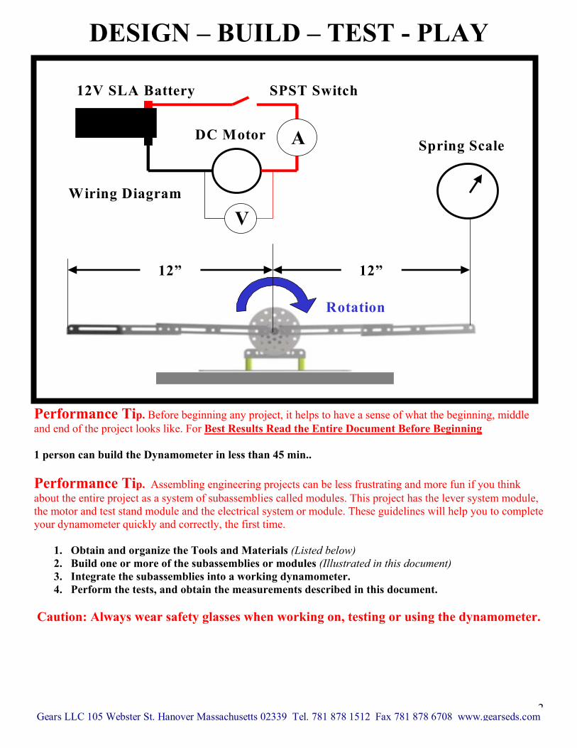
Organize the Tools and Materials The dynamometer can be completed quickly and with minimal frustration and mistakes by taking the time to read through the directions and readying the necessary tools and materials before beginning the assembly. Required Tools Safety Glasses 2-3 Phillips Head Screwdrivers 5/16” Combination Wrench (For the Stand Offs) 3/8” Combination Wrench 6” Needle Nose Pliers
5/64, 6/32 Allen Wrenches or Hex Keys Dial Calipers and Tape Measures Wire stripping and crimping tool Multimeter (10 ampere capacity) Test Leads
Materials Use the GEARS-IDS online catalog of parts and components to identify the following components. Structural Components 1 6x9 Flat Plates GIDS-SC-10002 4 13 Hole Angles GIDS-SC-10006 1 7 Hole Angles GIDS-SC-10007 1 1/4” Hex Adapter GIDS-SC-10013-1875 1 ½” Shaft Collar 1 M15 Motor Mount GIDS-SC-10009 1 M13 Motor Mount GIDS-SC-10008 Electrical Components 1 Gear Head Electric Motor GIDS-IM15 1 SPST toggle Switch GIDS-EC-10003TS 1 12 Volt SLA Battery GIDS-EC-10006 #14-16 ga. Insulated Wire (Approx. 30”) #14-16 ga. Insulted Male Quick Disconnects #14-16 ga. Insulted female Quick Disconnects
Hardware 1 ½” Shaft Collar 20+/- #10-24 x 3/8” PH Machine Screws 2 #10-32 x ¾ PH Machine Screws (Motor Mounting) 20+/- #10 Nuts, flat washers and star lock washers 2 #10-24 hex standoffs Miscellaneous Supplies and Materials Wood Mounting Base (See picture at the end of the document) Wood screws for mounting 6x9” base plate 5-10 lb spring scale Wire coat hanger or 1/16” welding rod Multimeter Photo Tachometer or Mechanical Tachometer
Performance Tip. Go to www.gearseds.com to download a complete catalog and description of GEARS-IDS Invention and Design System components. This will help you locate the parts. Construct the Dynamometer using these Subassemblies Note: 2 assemblies are required for the right and left side frames 1. Base Plate and Motor and Mount 2. Lever Arm Assembly 3. Electrical Circuit
3
Gears LLC 105 Webster St. Hanover Massachusetts 02339 Tel. 781 878 1512 Fax 781 878 6708 www.gearseds.com
SBNL Sil I
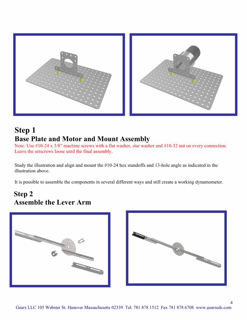
tep 1 ase Plate and Motor and Mount Assembly
ote: Use #10-24 x 3/8” machine screws with a flat washer, star washer and #10-32 nut on every connection. eave the setscrews loose until the final assembly.
tudy the illustration and align and mount the #10-24 hex standoffs and 13-hole angle as indicated in the lustration above.
t is possible to assemble the components in several different ways and still create a working dynamometer.
Step 2 Assemble the Lever Arm
4 Gears LLC 105 Webster St. Hanover Massachusetts 02339 Tel. 781 878 1512 Fax 781 878 6708 www.gearseds.com

Assemble the lever arms so that the outer most holes are approximately 12 inches (1 foot) from the center of the hex adapter. (See illustration on page 2) The lever arm assembly must be symmetrical. The reason there are two arms, is to balance the torques acting on the motor shaft. When the motor is energized and begins to turn, the force needed to lift one arm is balanced by the counter weight of the other arm. This ensures that the torque being measured is the torque developed by the motor and battery and not by the additional weight of the arm. Note: The lever arms must be rigid. Rigidity prevents unwanted movement and deformation (bending) during testing. A loosely constructed lever arm will fail under the stress of testing. The lever will need to be strong enough to withstand the occasional “Hammering” it will receive when the motor is turned on without supporting the lever arm, Be certain to use flat washers to distribute the clamping pressures and lock washers to prevent machine screws from working loose.
12V SLA Battery SPST Switch
DC Motor
Wiring Diagram
V
A
Voltmeter Wired in Parallel
Ammeter Wired in Series
Step 3 Wire the Electrical Circuit
CAUTION: Always
determine motor rotation direction before operating
the dynamometer
The schematic diagram on the right illustrates how to wire the motor, battery, switch and ammeter in series. The voltmeter is attached across the motor leads as shown. The polarity of the circuit determines the direction of motor rotation. Reversing the batteryleads will cause the motor to rotate in the opposite direction. Caution: Be certain that you experiment with the completed circuit and have determined the motorrotation BEFORE you attach the lever arm assembly
Mount the Switch as shown in the illustration on the left. Mount the battery securely to the 6 x 9” base plate, or secure the entire assembly to a wooden platform and mount the battery to the wooden platform. Be certain to wire and test the motor rotation direction BEFORE attaching the lever arm assembly. If necessary, move the motor mounts and stand offs, 2 holes nearer the front of the
G
Front of 6” x9” Plate
6”x 9” plate.5 ears LLC 105 Webster St. Hanover Massachusetts 02339 Tel. 781 878 1512 Fax 781 878 6708 www.gearseds.com
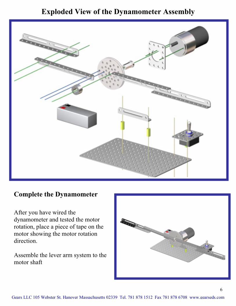
Exploded View of the Dynamometer Assembly
G
rotation irection.
e lever arm system to the otor shaft
Complete the Dynamometer
After you have wired the dynamometer and tested the motor rotation, place a piece of tape on the motor showing the motord Assemble thm
ears LLC 105 Webster St. Hanover Massachusetts 02339
6
Tel. 781 878 1512 Fax 781 878 6708 www.gearseds.com

Using the GEARS-IDS Dynamometer
How Motors Work Fixed magnet DC electric motors create twisting forces (Torque) and rotary motion (RPM) through the creation of unbalanced magnetic forces between the fixed magnetic fields inside the motor and the opposing electromagnetic fields developed in the rotating armature. Click here to view an interactive flash animation that illustrates the operation of a fixed magnet DC motor. Note: Fixed magnet DC motors are also called permanent magnet DC motors. GEARS-IDS™ Gear Head Motor Components
Gears LLC 105 Webster St. Hanover Massachusetts 02339
7
Tel. 781 878 1512 Fax 781 878 6708 www.gearseds.com
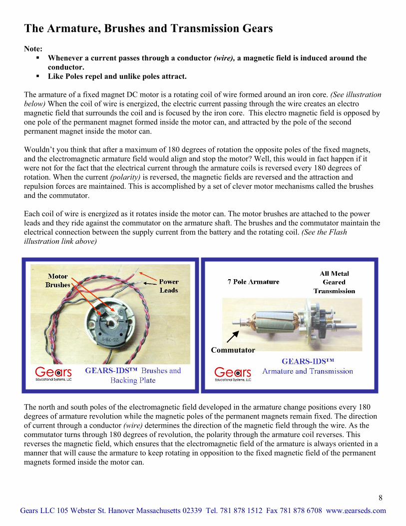
The Armature, Brushes and Transmission Gears Note: Whenever a current passes through a conductor (wire), a magnetic field is induced around the
conductor. Like Poles repel and unlike poles attract.
The armature of a fixed magnet DC motor is a rotating coil of wire formed around an iron core. (See illustration below) When the coil of wire is energized, the electric current passing through the wire creates an electro magnetic field that surrounds the coil and is focused by the iron core. This electro magnetic field is opposed by one pole of the permanent magnet formed inside the motor can, and attracted by the pole of the second permanent magnet inside the motor can. Wouldn’t you think that after a maximum of 180 degrees of rotation the opposite poles of the fixed magnets, and the electromagnetic armature field would align and stop the motor? Well, this would in fact happen if it were not for the fact that the electrical current through the armature coils is reversed every 180 degrees of rotation. When the current (polarity) is reversed, the magnetic fields are reversed and the attraction and repulsion forces are maintained. This is accomplished by a set of clever motor mechanisms called the brushes and the commutator. Each coil of wire is energized as it rotates inside the motor can. The motor brushes are attached to the power leads and they ride against the commutator on the armature shaft. The brushes and the commutator maintain the electrical connection between the supply current from the battery and the rotating coil. (See the Flash illustration link above)
Commutator
The north and south poles of the electromagnetic field developed in the armature change positions every 180 degrees of armature revolution while the magnetic poles of the permanent magnets remain fixed. The direction of current through a conductor (wire) determines the direction of the magnetic field through the wire. As the commutator turns through 180 degrees of revolution, the polarity through the armature coil reverses. This reverses the magnetic field, which ensures that the electromagnetic field of the armature is always oriented in a manner that will cause the armature to keep rotating in opposition to the fixed magnetic field of the permanent magnets formed inside the motor can.
8 Gears LLC 105 Webster St. Hanover Massachusetts 02339 Tel. 781 878 1512 Fax 781 878 6708 www.gearseds.com

Clearly, the strength of the turning force (torque) of an electric motor is proportional to the strength of the interaction between fixed magnet fields and the electromagnetic fields of the rotating armature coils.
(load).
The torque generated by the magnetic fields is proportional to the amount of current (amperage) passing through the armature coil. The rotational speed of the motor is proportional to the voltage applied to the motor and the work being done by the motor Fixed Magnet DC Motor Characteristics Torque and RPM of Fixed Magnet DC Motors Fixed magnet DC electric motors typically turn at speeds The motor shaft of the gear head motors used in the GEAvolts of electrical pressure. The rpm difference is due to thhead). The reduction ratio is approximately 20:1. This geaincreasing output shaft torque. Torque Torque is a force that causes a shaft or an object to turn orturning force) is a product of the measured force x the disillustration below, the force (Scale reading) is approximatfrom the center of rotation. In this case the motor Torque Stall Torque When a motor is stalled, a condition where the motor shafenergized, the motor will exhibit maximum torque. In thisbe zero. Maximum RPM A free spinning electric motor running at maximum rpm ftorque. When the shaft is loaded and the motor begins wo Maximum Current When a DC motor is stalled the armature coil draws the mof the coil and the battery’s ability to produce maximum cenergy or current the coil can draw. The torque produced the armature coil. In the stall condition a DC motor producurrent. The stall condition is harmful and inefficient to Dmaximum heating in the coil wires. This heat will burn ofcoil wire and premature motor failure. Testing and analyzmotor to stall conditions. Do not operate DC motors in the
Gears LLC 105 Webster St. Hanover Massachusetts 02339 T
9
between 2500-5000 rpm (Revolutions per minute).
RS-IDS™ kit turn at approximately 250 +/- rpm at 12 e gear reduction of the motor transmission (Gear r reduction serves to reduce output shaft rpm while
twist. The value or amount of torque (Twisting or tance from the point of rotation. In the example ely 1.125 lbs. The scale is attached at a point 12” = 1.125 lbs x 12 in. or 13.5 lb ins. of torque.
t is prevented from turning while the armature coil is case the torque will be maximum, and the rpm will
or a given voltage typically produces little or no rking, the torque increases and the rpm drops.
aximum amount of electrical energy. The resistance urrent at 12 volts limits the amount of electrical by a DC motor is proportional to the current drawn by ces maximum torque while drawing maximum C motors, since the increased current draw produces f the motor insulation causing short circuits within the ing DC motor performance requires subjecting the stall condition for more than 5-10 seconds at a time.
el. 781 878 1512 Fax 781 878 6708 www.gearseds.com

Cauti
AL
to th
Setting Up the GEARS-IDS™ Dynamometer
WA
Hint: Pin
Gears
10
on: ys clamp or affix the dynamometer securely to a table or bench top to prevent
d. Be
G ON THE DYNAMOMETER
e 6 x9” base plate.
12”
GEARS-IDS™ Dynamometer
Spring Scale
Alwaaccidental tipping or rolling of the dynamometer during operation. The motor and lever arm will turn forcefully and rapidly when the motor is energizecertain that you know which way the motor will turn before attaching the lever arm or using the dynamometer. Keep fingers and hands clear of the rotating lever arms.
YS WEAR SAFETY GLASSES WHEN USING OR WORKIN
lace a soft foam or rubber pad under the scale side of the lever arm to prevent it from banging
LLC 105 Webster St. Hanover Massachusetts 02339 Tel. 781 878 1512 Fax 781 878 6708 www.gearseds.com
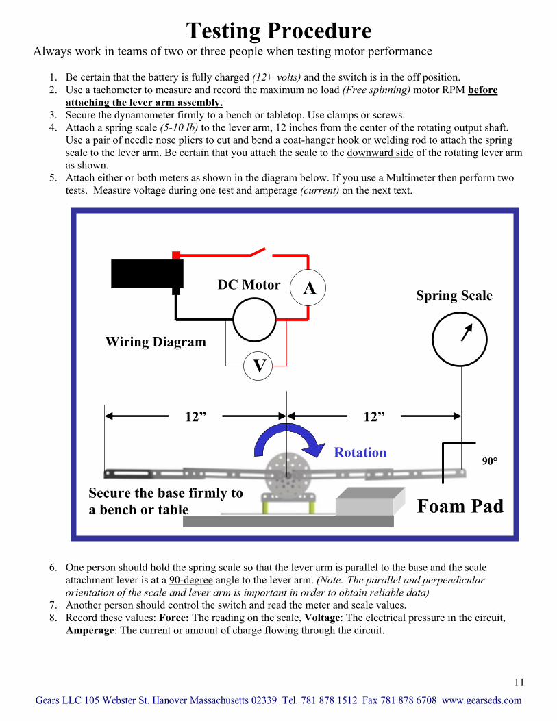
Testing Procedure Always work in teams of two rformance
1. Be certain that the battery is fully charged (12+ volts) and the switch is in the off position. 2. Use a tachometer to measure and record the maximum no load (Free spinning) motor RPM before
or three people when testing motor pe
attaching the lever arm assembly. 3. Secure the dynamometer firmly to a bench or tabletop. Use clamps or screws. 4. Attach a spring scale (5-10 lb) to the lever arm, 12 inches from the center of the rotating output shaft.
g Use a pair of needle nose pliers to cut and bend a coat-hanger hook or welding rod to attach the sprinscale to the lever arm. Be certain that you attach the scale to the downward side of the rotating lever arm
. Onatta
as shown. 5. Attach either or both meters as shown in the diagram below. If you use a Multimeter then perform two
tests. Measure voltage during one test and amperage (current) on the next text.
6
ori. An
78. Re
Am
Gears LLC
11
e person should hold the spring scale so that the lever arm is parallel to the bachment lever is at a 90-degree
12V SLA Battery SPST Switch
se and the scale angle to the lever arm. (Note: The parallel and perpendicular
entation of the scale and lever arm is important in order to obtain reliable data) other person should control the switch and read the meter and scale values.
uit, cord these values: Force: The reading on the scale, Voltage: The electrical pressure in the circperage: The current or amount of charge flowing through the circuit.
DC Motor
Wiring Diagram
12”12”
Spring Scale
Rotation
V
A
Secure the base firmly to a bench or table
90°
Foam Pad
105 Webster St. Hanover Massachusetts 02339 Tel. 781 878 1512 Fax 781 878 6708 www.gearseds.com
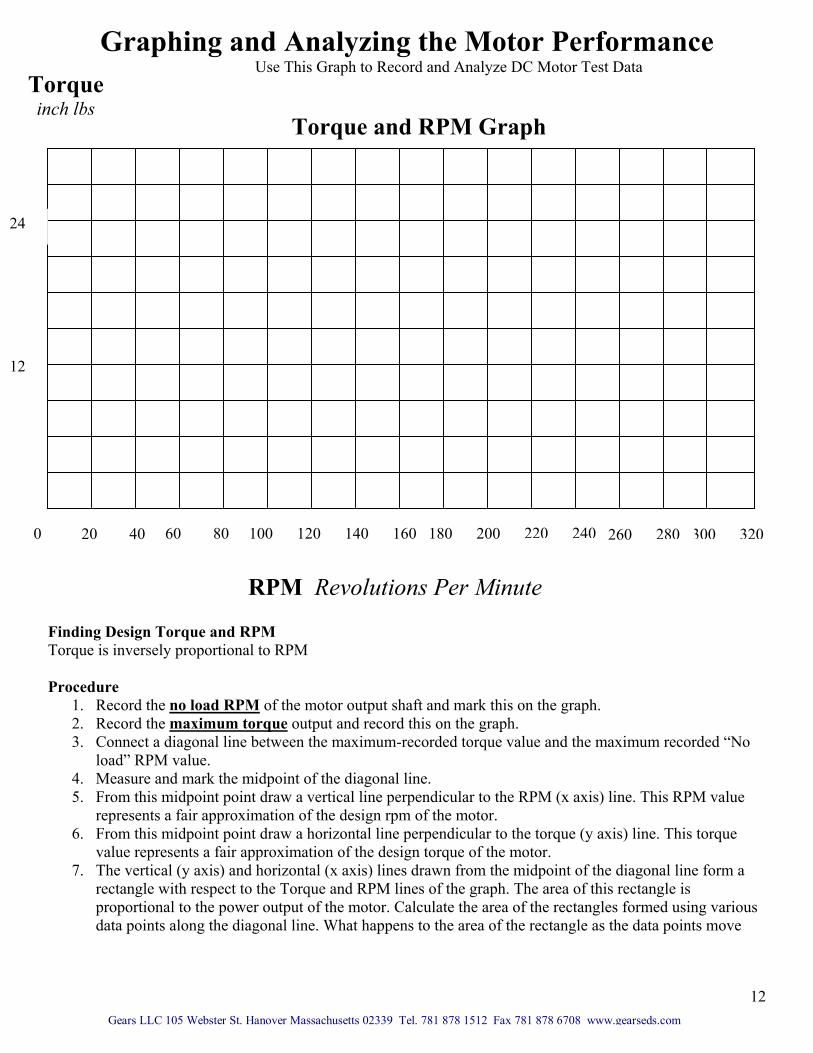
Use This Graph to Record and Analyze DC Motor Test Data
Procedure
1. Record the no load RP
Graphing and Analyzing the Motor Performance
Finding Design Torque and Torque is inversely proportion
40 20 60 80 100 120 140 160 180 200 260
Torque inch lbs
12
24
2. Record the maximum3. Connect a diagonal lin
load” RPM value. 4. Measure and mark the 5. From this midpoint po
represents a fair approx6. From this midpoint po
value represents a fair 7. The vertical (y axis) an
rectangle with respect proportional to the powdata points along the d
Gears LLC 105 Webster St
RPM Revolutions Per Minute
M
RPM al to RPM
of the motor output shaft and mark this torque output and record this on the graph.e between the maximum-recorded torque va
midpoint of the diagonal line. int draw a vertical line perpendicular to the imation of the design rpm of the motor.
int draw a horizontal line perpendicular to thapproximation of the design torque of the md horizontal (x axis) lines drawn from the m
to the Torque and RPM lines of the graph. Ter output of the motor. Calculate the area o
iagonal line. What happens to the area of th
. Hanover Massachusetts 02339 Tel. 781 878 1512 Fax 7
220
on the g lue and
RPM (x
e torquotor. idpoinhe areaf the ree rectan
81 878 67
240
raph.
the maximum reco
axis) line. This RP
e (y axis) line. Thi
t of the diagonal lin of this rectangle ictangles formed usgle as the data poin
08 www.gearseds.com
300
0 280rded “N
M valu
s torque
e forms ing varits mov
320
Torque and RPM Graph
12
o
e
a
ous e
13
What is the rate of change in the power (area of the rectangle) of the otor as the torque or RPM increase or decrease?
Tor
away from the center of the diagonal line.m
que x RPM = Motor Power. Continually operating the motor in successively higher torque ranges does not
nec lanation of why. You can see from studto produce more torque also increases the current drawn through the armature windings. This increased current dra es their electrical resistance.
essarily produce more power. In fact the opposite occurs. Here is an expying the graph that torque increases while rpm (rotational speed) decreases. In addition, requiring the motor
w heats the motor armature windings which in turn increas Electrical resistance of a n Evecurrent nt of electrical energy ava rs ineffici trical energy)power shaft is not turning. There Finding Design Torque and Amperage Torque is proportional to RPM After finding the design torque rent that the motor draws from the battery. This will allow you ount of “Run time” you can expect from a battery with a known capacity. Note: Determining the battery capacity in amp-hours is accomplished by measuring the rate of battery discharge or current output, over time. This is the subject of another GEARS-IDS™ lesson. Procedure Follow the previously described testing procedure and note the following.
1. Be certain that you are using an ammeter or Multimeter with a 10-ampere capacity. 2. Connect the ammeter or Multimeter in series with the motor circuit as shown in the circuit diagram 3. If you have two meters then connect both an ammeter or Multimeter in series with the circuit and a
voltmeter or additional Multimeter in parallel across the motor leads as shown in the circuit diagram 4. Create a stall condition as described above. 5. Record these values; Force The reading on the scale, Voltage The electrical pressure in the circuit,
Amperage: The current or amount of charge flowing through the circuit. 6. Convert the force reading to inch lbs. of torque as described earlier 7. If the circuit voltage drops below 12 volts while the motor is stalled then the battery is either:
a. Not fully charged. Note a battery that reads 12 volts is not necessarily fully charged. A dead battery will often show a standing value of 12 volts but the voltage will drop under load. Stalling the motor puts a significant load on the battery.
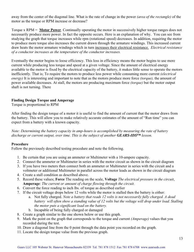
b. Incapable of being fully charged or damaged 8. Create a graph similar to the one shown below or use this graph. 9. Mark the point on the graph that corresponds to the torque and current (Amperage) values that you
recorded during the test. 10. Draw a diagonal line from the 0 point through the data point you recorded on the graph. 11. Locate the design torque value from the previous graph.
co ductor increases as the temperature of the conductor increases.
ntually the motor begins to loose efficiency. This loss in efficiency means the motor begins to use more while producing less torque and speed at a given voltage. Since the amou
ilable to the motor is fixed by the electrical capacity of the battery, it makes little sense to operate the motoently. That is; To require the motors to produce less power while consuming more current (elec It is interesting and important to note that as the motors produce more force (torque), the amount of
available decreases. At stall, the motors are producing maximum force (torque) but the motor output
of a motor it is useful to find the amount of cur to make relatively accurate estimates of the am
Gears LLC 105 Webster St. Hanover Massachusetts 02339 Tel. 781 878 1512 Fax 781 878 6708 www.gearseds.com

12. Draw a horizontal line from this torque value through the diagonal line of the graph. 13. From the intersection of the horizontal (Torque) line and the diagonal line, draw a vertical line
e approximate current draw and torque of the motor at the design or midpoint rpm.
aph In
downward through the amperage scale. 14. This amperage or current value represents th
orque Torque and Amperage GrTch Pounds
12
24
14
Th Th Moto Re
1 2 3 4 5 6 7 8
Current in Amperes
e data acquired from these tests can be used to approximate:
e design motor power output r run time based on (tested) battery capacity
quired speed or torque drive ratios
15
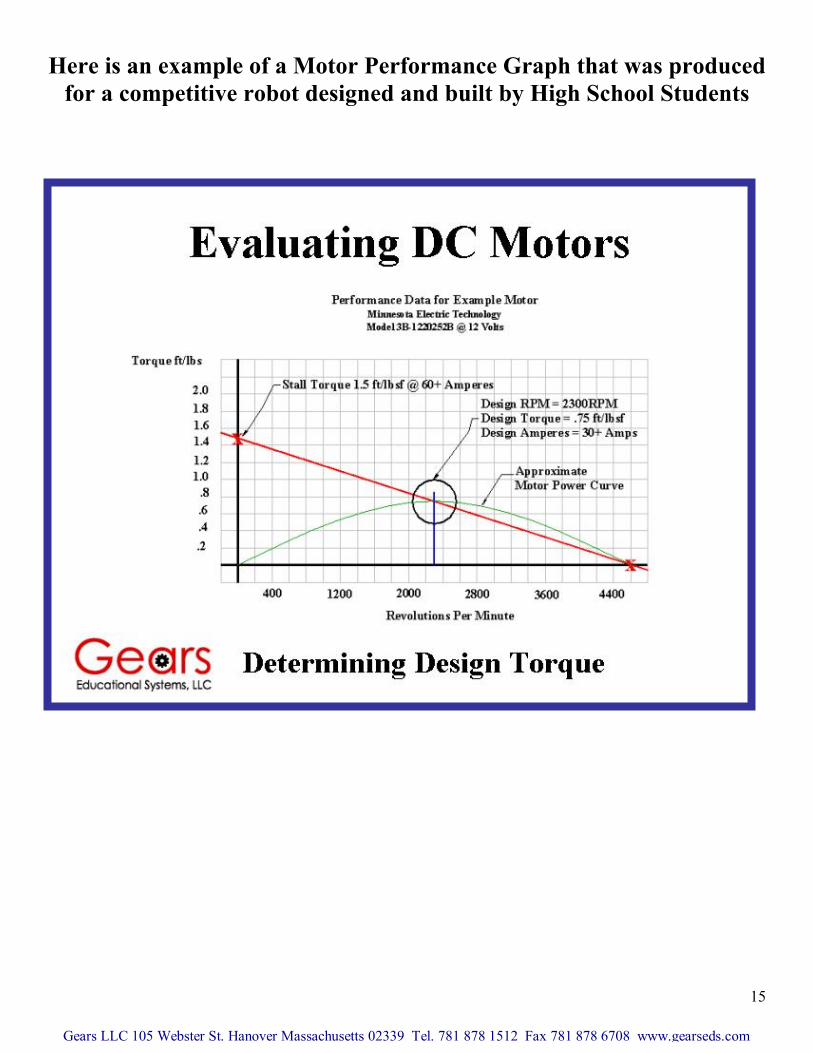
Here is an example of a Motor Performance Graph that was produced for a competitive robot designed and built by High School Students
Gears LLC 105 Webster St. Hanover Massachusetts 02339 Tel. 781 878 1512 Fax 781 878 6708 www.gearseds.com