Embed Size (px)
Citation preview

Journal of Physics Conference Series
OPEN ACCESS
Building a parabolic solar concentrator prototypeTo cite this article J F M Escobar-Romero et al 2011 J Phys Conf Ser 274 012104
View the article online for updates and enhancements
You may also like(Battery Division Technology Award) Lead-Carbon Ultracapacitors How Why andWhere is the TechnologyAshok Kumar Shukla
-
The Status of SOFC and SOEC RampD inthe European Fuel Cell and HydrogenJoint Undertaking ProgrammeAntonio Aguilo-Rullan Mirela AtanasiuBart Biebuyck et al
-
The logistics approach to perspectives forthe digital technologies in RussiaS Barykin and L Shamina
-
This content was downloaded from IP address 175215829 on 11022022 at 0318
Building a parabolic solar concentrator prototype
J F M Escobar-Romero1 S Vaacutezquez y Montiel1 F Granados-Agustiacuten1 V M Cruz-
Martiacutenez2 E Rodriacuteguez-Rivera1 L Martiacutenez-Yaacutentildeez1
1 INAOE Luis Enrique Erro 1 Tonantzintla Pue 72840 Mex
2 Universidad Tecnologica de la Mixteca Camino a Acatilma Km 25 Huajuapan de
Leon Oax 69000 Mex
jfmescobaryahoocom
Abstract In order to not further degrade the environment people have been seeking to replace
non-renewable natural resources such as fossil fuels by developing technologies that are based
on renewable resources An example of these technologies is solar energy In this paper we
show the building and test of a solar parabolic concentrator as a prototype for the production of
steam that can be coupled to a turbine to generate electricity or a steam engine in any particular
industrial process
1 Introduction The optical systems based on solar energy have been developed and implemented since the XIX
century The maximum development of these systems was not until 1970 due to the global oil crisis
leading to the search for alternative sources of energy such as wind bio-fuels solar energy etc There
is a whole range of technological options designed to take advantage of the solar energy but only a few
are popularly known for example the solar systems for hot water or photovoltaic systems to produce
electricity However there are other technologies that are mature enough to be commercialized on a
large scale that are unknown by most people An example of these is the design featuring the semi-
cylindrical parabolic solar concentrator A semi-cylindrical parabolic solar concentrator is based upon
the direct conversion of solar energy to thermal energy by heating a working fluid reaching
temperatures above 300 ordmC depending on the efficiency of the concentrator It is for this reason that
parabolic solar concentrators are suitable for use in a wide variety of industrial processes which use
thermal energy such as dairy processed waste electricity etc replacing in this way the use of fossil
fuels An example of the application of these parabolic solar concentrators are the eight so-called solar
thermal power plants SEGS-II III hellip IX built in California USA with more of 25 million square
meters of parabolic solar concentrators In the next section we describe the process of building and
testing of our semi-cylindrical parabolic solar concentrator prototype
2 Building of the parabolic solar concentrator prototype The main basis of the prototype solar concentrator is a parabolic reflective surface which takes
advantage of every ray of light coming from the infinite is concentrated at the focus In the focus of
the parabolic surface is placed a metal tube which serves to transform solar energy to thermal energy
By circulating a fluid inside the metal tube is achieved above in our case we use water which will be
converted in steam by the transformation of energy in this area For make more efficient the energy
XVII Reunioacuten Iberoamericana de Oacuteptica amp X Encuentro de Oacuteptica Laacuteseres y Aplicaciones IOP PublishingJournal of Physics Conference Series 274 (2011) 012104 doi1010881742-65962741012104
Published under licence by IOP Publishing Ltd 1
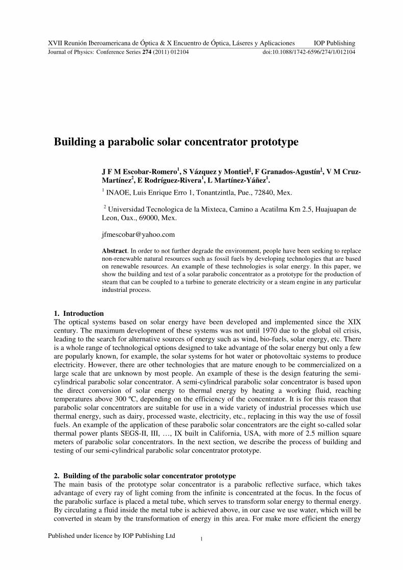
transformation the metal tube is isolated from the environment through a glass tube with vacuum
between them figure 1
Figure 1 Parabolic solar concentrator prototype
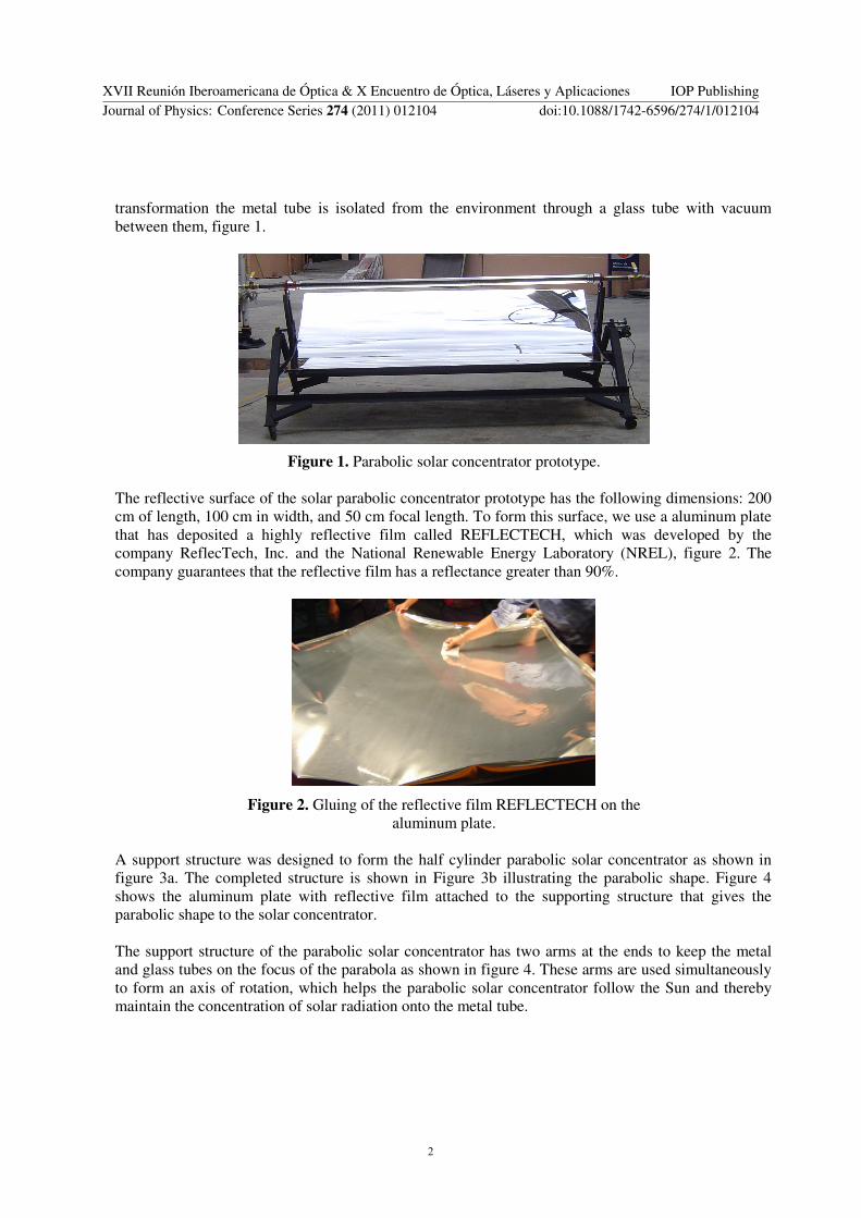
The reflective surface of the solar parabolic concentrator prototype has the following dimensions 200
cm of length 100 cm in width and 50 cm focal length To form this surface we use a aluminum plate
that has deposited a highly reflective film called REFLECTECH which was developed by the
company ReflecTech Inc and the National Renewable Energy Laboratory (NREL) figure 2 The
company guarantees that the reflective film has a reflectance greater than 90
Figure 2 Gluing of the reflective film REFLECTECH on the
aluminum plate
A support structure was designed to form the half cylinder parabolic solar concentrator as shown in
figure 3a The completed structure is shown in Figure 3b illustrating the parabolic shape Figure 4
shows the aluminum plate with reflective film attached to the supporting structure that gives the
parabolic shape to the solar concentrator
The support structure of the parabolic solar concentrator has two arms at the ends to keep the metal
and glass tubes on the focus of the parabola as shown in figure 4 These arms are used simultaneously
to form an axis of rotation which helps the parabolic solar concentrator follow the Sun and thereby
maintain the concentration of solar radiation onto the metal tube
XVII Reunioacuten Iberoamericana de Oacuteptica amp X Encuentro de Oacuteptica Laacuteseres y Aplicaciones IOP PublishingJournal of Physics Conference Series 274 (2011) 012104 doi1010881742-65962741012104
2
(a) (b)
Figure 3 Support structure of the parabolic solar concentrator
Figure 4 Aluminum plate with the reflective film attached to
the support structure
Next two connectors of stainless steel coupler were manufactured to join the metal tube to the glass
tube These are used to maintain a separation between the two tubes and as shown in figure 5 the
joint between the tubes and connectors was sealed with high temperature silicone glue In one of the
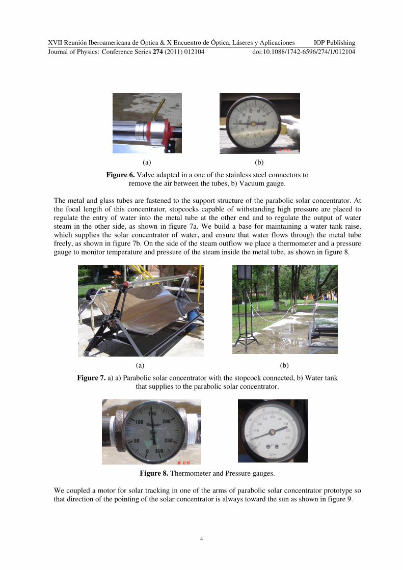
connectors as shown in figure 6b we placed a valve to remove air between the tubes The purpose of
this valve was to transfer heat to the water inside the metal tube as efficiently as possible Then we
use a vacuum pump to remove the air between the tubes A vacuum gauge was used to monitor the
pressure between the tubes to achieve a pressure of 420 millimeters of mercury
Figure 5 Join and sealed of connectors to the metal and glass tubes
XVII Reunioacuten Iberoamericana de Oacuteptica amp X Encuentro de Oacuteptica Laacuteseres y Aplicaciones IOP PublishingJournal of Physics Conference Series 274 (2011) 012104 doi1010881742-65962741012104
3
(a) (b)
Figure 6 Valve adapted in a one of the stainless steel connectors to
remove the air between the tubes b) Vacuum gauge
The metal and glass tubes are fastened to the support structure of the parabolic solar concentrator At
the focal length of this concentrator stopcocks capable of withstanding high pressure are placed to
regulate the entry of water into the metal tube at the other end and to regulate the output of water
steam in the other side as shown in figure 7a We build a base for maintaining a water tank raise
which supplies the solar concentrator of water and ensure that water flows through the metal tube
freely as shown in figure 7b On the side of the steam outflow we place a thermometer and a pressure
gauge to monitor temperature and pressure of the steam inside the metal tube as shown in figure 8
(a) (b)
Figure 7 a) a) Parabolic solar concentrator with the stopcock connected b) Water tank
that supplies to the parabolic solar concentrator
Figure 8 Thermometer and Pressure gauges
We coupled a motor for solar tracking in one of the arms of parabolic solar concentrator prototype so
that direction of the pointing of the solar concentrator is always toward the sun as shown in figure 9
XVII Reunioacuten Iberoamericana de Oacuteptica amp X Encuentro de Oacuteptica Laacuteseres y Aplicaciones IOP PublishingJournal of Physics Conference Series 274 (2011) 012104 doi1010881742-65962741012104
4
Figure 9 Motor coupled to the parabolic solar concentrator prototype
3 Results After the construction of the parabolic solar concentrator prototype we proceeded to do performance
tests Figure 10 shows the steam obtained with this solar concentrator after reaching a temperature of
200 degC and a pressure of 12kgcm2 on a sunny day and in 25 minutes Table 1 shows some of the
temperatures and pressures achieved with the parabolic solar concentrator prototype in one day with
some clouds These tests were made during the rainy season
Figure 10 Steam obtained with the parabolic solar concentrator prototype
Table 1 Temperature y pressure obtained in one sunny day
Time Temperatures (ordmC) Pressures (kgcm2)
1215 42 0
1220 70 075
1225 90 15
1230 110 2
1235 125 3
1240 140 48
1245 155 66
1250 65 0
1255 70 05
XVII Reunioacuten Iberoamericana de Oacuteptica amp X Encuentro de Oacuteptica Laacuteseres y Aplicaciones IOP PublishingJournal of Physics Conference Series 274 (2011) 012104 doi1010881742-65962741012104
5
4 Conclusions We have built a parabolic solar concentrator prototype with materials that can be found in the market
easily and cheaply with the exception of reflective film which was imported
On a clear day we can achieve temperatures above 200 ordmC and pressures up to 12 Kgcm2 Our design
could have achieved a higher temperature and pressure but this design is constrained by the errors
associated with the shape of the parabolic surface of the parabolic solar concentrator prototype
Another source of error that affects the heat transfer to the water inside the metal tube is the vacuum
leak between the seals of silicone of the tubes and couplers
In this work we have made a qualitative evaluation of the operation of the parabolic solar concentrator
prototype We need still to make a quantitative evaluation of it to have a real evaluation of the
prototype
References [1] Duffie J A and Beckman W A 1980 Solar engineering of thermal processes (New York John
Wiley and Sons Inc)
[2] Folaranmi J 2009 Design Construction and Testing of a Parabolic Solar Steam Generator
Leonardo Electronic Journal of Practices and Technologies 115 14
[3] Ibantildeez P M Rosell Plo J R Rossell Urrutia J J 2004 Tecnologiacutea Solar Energiacuteas Renovables
(Madrid Grupo Mundi-Prensa)
[4] Meinel A B and Meinel M P 1976 Applied solar energy An Introduction (Addison-Wesley
Publishing Company)
[5] Osborn D E (Ed) 1993 Selected papers on solar radiation and solar thermal systems SPIE-The
International Society for Optical Engineering Vol MS54
[6] Rabl A 1985 Active solar collectors and their applications (Oxford University Press)
[7] Site web of REFLECTECH httpwwwreflectechsolarcom
[8] Site web httpwwwsener-power-processcomENERGIA
[9] Winter Plants C J Sizmann L L Vant-Hull (Eds) 1991 Solar Power Plants fundamentals
technology systems economics (Springer-Verlag)
XVII Reunioacuten Iberoamericana de Oacuteptica amp X Encuentro de Oacuteptica Laacuteseres y Aplicaciones IOP PublishingJournal of Physics Conference Series 274 (2011) 012104 doi1010881742-65962741012104
6
Building a parabolic solar concentrator prototype
J F M Escobar-Romero1 S Vaacutezquez y Montiel1 F Granados-Agustiacuten1 V M Cruz-
Martiacutenez2 E Rodriacuteguez-Rivera1 L Martiacutenez-Yaacutentildeez1
1 INAOE Luis Enrique Erro 1 Tonantzintla Pue 72840 Mex
2 Universidad Tecnologica de la Mixteca Camino a Acatilma Km 25 Huajuapan de
Leon Oax 69000 Mex
jfmescobaryahoocom
Abstract In order to not further degrade the environment people have been seeking to replace
non-renewable natural resources such as fossil fuels by developing technologies that are based
on renewable resources An example of these technologies is solar energy In this paper we
show the building and test of a solar parabolic concentrator as a prototype for the production of
steam that can be coupled to a turbine to generate electricity or a steam engine in any particular
industrial process
1 Introduction The optical systems based on solar energy have been developed and implemented since the XIX
century The maximum development of these systems was not until 1970 due to the global oil crisis
leading to the search for alternative sources of energy such as wind bio-fuels solar energy etc There
is a whole range of technological options designed to take advantage of the solar energy but only a few
are popularly known for example the solar systems for hot water or photovoltaic systems to produce
electricity However there are other technologies that are mature enough to be commercialized on a
large scale that are unknown by most people An example of these is the design featuring the semi-
cylindrical parabolic solar concentrator A semi-cylindrical parabolic solar concentrator is based upon
the direct conversion of solar energy to thermal energy by heating a working fluid reaching
temperatures above 300 ordmC depending on the efficiency of the concentrator It is for this reason that
parabolic solar concentrators are suitable for use in a wide variety of industrial processes which use
thermal energy such as dairy processed waste electricity etc replacing in this way the use of fossil
fuels An example of the application of these parabolic solar concentrators are the eight so-called solar
thermal power plants SEGS-II III hellip IX built in California USA with more of 25 million square
meters of parabolic solar concentrators In the next section we describe the process of building and
testing of our semi-cylindrical parabolic solar concentrator prototype
2 Building of the parabolic solar concentrator prototype The main basis of the prototype solar concentrator is a parabolic reflective surface which takes
advantage of every ray of light coming from the infinite is concentrated at the focus In the focus of
the parabolic surface is placed a metal tube which serves to transform solar energy to thermal energy
By circulating a fluid inside the metal tube is achieved above in our case we use water which will be
converted in steam by the transformation of energy in this area For make more efficient the energy
XVII Reunioacuten Iberoamericana de Oacuteptica amp X Encuentro de Oacuteptica Laacuteseres y Aplicaciones IOP PublishingJournal of Physics Conference Series 274 (2011) 012104 doi1010881742-65962741012104
Published under licence by IOP Publishing Ltd 1
transformation the metal tube is isolated from the environment through a glass tube with vacuum
between them figure 1
Figure 1 Parabolic solar concentrator prototype
The reflective surface of the solar parabolic concentrator prototype has the following dimensions 200
cm of length 100 cm in width and 50 cm focal length To form this surface we use a aluminum plate
that has deposited a highly reflective film called REFLECTECH which was developed by the
company ReflecTech Inc and the National Renewable Energy Laboratory (NREL) figure 2 The
company guarantees that the reflective film has a reflectance greater than 90
Figure 2 Gluing of the reflective film REFLECTECH on the
aluminum plate
A support structure was designed to form the half cylinder parabolic solar concentrator as shown in
figure 3a The completed structure is shown in Figure 3b illustrating the parabolic shape Figure 4
shows the aluminum plate with reflective film attached to the supporting structure that gives the
parabolic shape to the solar concentrator
The support structure of the parabolic solar concentrator has two arms at the ends to keep the metal
and glass tubes on the focus of the parabola as shown in figure 4 These arms are used simultaneously
to form an axis of rotation which helps the parabolic solar concentrator follow the Sun and thereby
maintain the concentration of solar radiation onto the metal tube
XVII Reunioacuten Iberoamericana de Oacuteptica amp X Encuentro de Oacuteptica Laacuteseres y Aplicaciones IOP PublishingJournal of Physics Conference Series 274 (2011) 012104 doi1010881742-65962741012104
2
(a) (b)
Figure 3 Support structure of the parabolic solar concentrator
Figure 4 Aluminum plate with the reflective film attached to
the support structure
Next two connectors of stainless steel coupler were manufactured to join the metal tube to the glass
tube These are used to maintain a separation between the two tubes and as shown in figure 5 the
joint between the tubes and connectors was sealed with high temperature silicone glue In one of the
connectors as shown in figure 6b we placed a valve to remove air between the tubes The purpose of
this valve was to transfer heat to the water inside the metal tube as efficiently as possible Then we
use a vacuum pump to remove the air between the tubes A vacuum gauge was used to monitor the
pressure between the tubes to achieve a pressure of 420 millimeters of mercury
Figure 5 Join and sealed of connectors to the metal and glass tubes
XVII Reunioacuten Iberoamericana de Oacuteptica amp X Encuentro de Oacuteptica Laacuteseres y Aplicaciones IOP PublishingJournal of Physics Conference Series 274 (2011) 012104 doi1010881742-65962741012104
3
(a) (b)
Figure 6 Valve adapted in a one of the stainless steel connectors to
remove the air between the tubes b) Vacuum gauge
The metal and glass tubes are fastened to the support structure of the parabolic solar concentrator At
the focal length of this concentrator stopcocks capable of withstanding high pressure are placed to
regulate the entry of water into the metal tube at the other end and to regulate the output of water
steam in the other side as shown in figure 7a We build a base for maintaining a water tank raise
which supplies the solar concentrator of water and ensure that water flows through the metal tube
freely as shown in figure 7b On the side of the steam outflow we place a thermometer and a pressure
gauge to monitor temperature and pressure of the steam inside the metal tube as shown in figure 8
(a) (b)
Figure 7 a) a) Parabolic solar concentrator with the stopcock connected b) Water tank
that supplies to the parabolic solar concentrator
Figure 8 Thermometer and Pressure gauges
We coupled a motor for solar tracking in one of the arms of parabolic solar concentrator prototype so
that direction of the pointing of the solar concentrator is always toward the sun as shown in figure 9
XVII Reunioacuten Iberoamericana de Oacuteptica amp X Encuentro de Oacuteptica Laacuteseres y Aplicaciones IOP PublishingJournal of Physics Conference Series 274 (2011) 012104 doi1010881742-65962741012104
4
Figure 9 Motor coupled to the parabolic solar concentrator prototype
3 Results After the construction of the parabolic solar concentrator prototype we proceeded to do performance
tests Figure 10 shows the steam obtained with this solar concentrator after reaching a temperature of
200 degC and a pressure of 12kgcm2 on a sunny day and in 25 minutes Table 1 shows some of the
temperatures and pressures achieved with the parabolic solar concentrator prototype in one day with
some clouds These tests were made during the rainy season
Figure 10 Steam obtained with the parabolic solar concentrator prototype
Table 1 Temperature y pressure obtained in one sunny day
Time Temperatures (ordmC) Pressures (kgcm2)
1215 42 0
1220 70 075
1225 90 15
1230 110 2
1235 125 3
1240 140 48
1245 155 66
1250 65 0
1255 70 05
XVII Reunioacuten Iberoamericana de Oacuteptica amp X Encuentro de Oacuteptica Laacuteseres y Aplicaciones IOP PublishingJournal of Physics Conference Series 274 (2011) 012104 doi1010881742-65962741012104
5
4 Conclusions We have built a parabolic solar concentrator prototype with materials that can be found in the market
easily and cheaply with the exception of reflective film which was imported
On a clear day we can achieve temperatures above 200 ordmC and pressures up to 12 Kgcm2 Our design
could have achieved a higher temperature and pressure but this design is constrained by the errors
associated with the shape of the parabolic surface of the parabolic solar concentrator prototype
Another source of error that affects the heat transfer to the water inside the metal tube is the vacuum
leak between the seals of silicone of the tubes and couplers
In this work we have made a qualitative evaluation of the operation of the parabolic solar concentrator
prototype We need still to make a quantitative evaluation of it to have a real evaluation of the
prototype
References [1] Duffie J A and Beckman W A 1980 Solar engineering of thermal processes (New York John
Wiley and Sons Inc)
[2] Folaranmi J 2009 Design Construction and Testing of a Parabolic Solar Steam Generator
Leonardo Electronic Journal of Practices and Technologies 115 14
[3] Ibantildeez P M Rosell Plo J R Rossell Urrutia J J 2004 Tecnologiacutea Solar Energiacuteas Renovables
(Madrid Grupo Mundi-Prensa)
[4] Meinel A B and Meinel M P 1976 Applied solar energy An Introduction (Addison-Wesley
Publishing Company)
[5] Osborn D E (Ed) 1993 Selected papers on solar radiation and solar thermal systems SPIE-The
International Society for Optical Engineering Vol MS54
[6] Rabl A 1985 Active solar collectors and their applications (Oxford University Press)
[7] Site web of REFLECTECH httpwwwreflectechsolarcom
[8] Site web httpwwwsener-power-processcomENERGIA
[9] Winter Plants C J Sizmann L L Vant-Hull (Eds) 1991 Solar Power Plants fundamentals
technology systems economics (Springer-Verlag)
XVII Reunioacuten Iberoamericana de Oacuteptica amp X Encuentro de Oacuteptica Laacuteseres y Aplicaciones IOP PublishingJournal of Physics Conference Series 274 (2011) 012104 doi1010881742-65962741012104
6

(a) (b)
Figure 3 Support structure of the parabolic solar concentrator
Figure 4 Aluminum plate with the reflective film attached to
the support structure
Next two connectors of stainless steel coupler were manufactured to join the metal tube to the glass
tube These are used to maintain a separation between the two tubes and as shown in figure 5 the
joint between the tubes and connectors was sealed with high temperature silicone glue In one of the
connectors as shown in figure 6b we placed a valve to remove air between the tubes The purpose of
this valve was to transfer heat to the water inside the metal tube as efficiently as possible Then we
use a vacuum pump to remove the air between the tubes A vacuum gauge was used to monitor the
pressure between the tubes to achieve a pressure of 420 millimeters of mercury
Figure 5 Join and sealed of connectors to the metal and glass tubes
XVII Reunioacuten Iberoamericana de Oacuteptica amp X Encuentro de Oacuteptica Laacuteseres y Aplicaciones IOP PublishingJournal of Physics Conference Series 274 (2011) 012104 doi1010881742-65962741012104
3
(a) (b)
Figure 6 Valve adapted in a one of the stainless steel connectors to
remove the air between the tubes b) Vacuum gauge
The metal and glass tubes are fastened to the support structure of the parabolic solar concentrator At
the focal length of this concentrator stopcocks capable of withstanding high pressure are placed to
regulate the entry of water into the metal tube at the other end and to regulate the output of water
steam in the other side as shown in figure 7a We build a base for maintaining a water tank raise
which supplies the solar concentrator of water and ensure that water flows through the metal tube
freely as shown in figure 7b On the side of the steam outflow we place a thermometer and a pressure
gauge to monitor temperature and pressure of the steam inside the metal tube as shown in figure 8
(a) (b)
Figure 7 a) a) Parabolic solar concentrator with the stopcock connected b) Water tank
that supplies to the parabolic solar concentrator
Figure 8 Thermometer and Pressure gauges
We coupled a motor for solar tracking in one of the arms of parabolic solar concentrator prototype so
that direction of the pointing of the solar concentrator is always toward the sun as shown in figure 9
XVII Reunioacuten Iberoamericana de Oacuteptica amp X Encuentro de Oacuteptica Laacuteseres y Aplicaciones IOP PublishingJournal of Physics Conference Series 274 (2011) 012104 doi1010881742-65962741012104
4
Figure 9 Motor coupled to the parabolic solar concentrator prototype
3 Results After the construction of the parabolic solar concentrator prototype we proceeded to do performance
tests Figure 10 shows the steam obtained with this solar concentrator after reaching a temperature of
200 degC and a pressure of 12kgcm2 on a sunny day and in 25 minutes Table 1 shows some of the
temperatures and pressures achieved with the parabolic solar concentrator prototype in one day with
some clouds These tests were made during the rainy season
Figure 10 Steam obtained with the parabolic solar concentrator prototype
Table 1 Temperature y pressure obtained in one sunny day
Time Temperatures (ordmC) Pressures (kgcm2)
1215 42 0
1220 70 075
1225 90 15
1230 110 2
1235 125 3
1240 140 48
1245 155 66
1250 65 0
1255 70 05
XVII Reunioacuten Iberoamericana de Oacuteptica amp X Encuentro de Oacuteptica Laacuteseres y Aplicaciones IOP PublishingJournal of Physics Conference Series 274 (2011) 012104 doi1010881742-65962741012104
5
4 Conclusions We have built a parabolic solar concentrator prototype with materials that can be found in the market
easily and cheaply with the exception of reflective film which was imported
On a clear day we can achieve temperatures above 200 ordmC and pressures up to 12 Kgcm2 Our design
could have achieved a higher temperature and pressure but this design is constrained by the errors
associated with the shape of the parabolic surface of the parabolic solar concentrator prototype
Another source of error that affects the heat transfer to the water inside the metal tube is the vacuum
leak between the seals of silicone of the tubes and couplers
In this work we have made a qualitative evaluation of the operation of the parabolic solar concentrator
prototype We need still to make a quantitative evaluation of it to have a real evaluation of the
prototype
References [1] Duffie J A and Beckman W A 1980 Solar engineering of thermal processes (New York John
Wiley and Sons Inc)
[2] Folaranmi J 2009 Design Construction and Testing of a Parabolic Solar Steam Generator
Leonardo Electronic Journal of Practices and Technologies 115 14
[3] Ibantildeez P M Rosell Plo J R Rossell Urrutia J J 2004 Tecnologiacutea Solar Energiacuteas Renovables
(Madrid Grupo Mundi-Prensa)
[4] Meinel A B and Meinel M P 1976 Applied solar energy An Introduction (Addison-Wesley
Publishing Company)
[5] Osborn D E (Ed) 1993 Selected papers on solar radiation and solar thermal systems SPIE-The
International Society for Optical Engineering Vol MS54
[6] Rabl A 1985 Active solar collectors and their applications (Oxford University Press)
[7] Site web of REFLECTECH httpwwwreflectechsolarcom
[8] Site web httpwwwsener-power-processcomENERGIA
[9] Winter Plants C J Sizmann L L Vant-Hull (Eds) 1991 Solar Power Plants fundamentals
technology systems economics (Springer-Verlag)
XVII Reunioacuten Iberoamericana de Oacuteptica amp X Encuentro de Oacuteptica Laacuteseres y Aplicaciones IOP PublishingJournal of Physics Conference Series 274 (2011) 012104 doi1010881742-65962741012104
6
(a) (b)
Figure 6 Valve adapted in a one of the stainless steel connectors to
remove the air between the tubes b) Vacuum gauge
The metal and glass tubes are fastened to the support structure of the parabolic solar concentrator At
the focal length of this concentrator stopcocks capable of withstanding high pressure are placed to
regulate the entry of water into the metal tube at the other end and to regulate the output of water
steam in the other side as shown in figure 7a We build a base for maintaining a water tank raise
which supplies the solar concentrator of water and ensure that water flows through the metal tube
freely as shown in figure 7b On the side of the steam outflow we place a thermometer and a pressure
gauge to monitor temperature and pressure of the steam inside the metal tube as shown in figure 8
(a) (b)
Figure 7 a) a) Parabolic solar concentrator with the stopcock connected b) Water tank
that supplies to the parabolic solar concentrator
Figure 8 Thermometer and Pressure gauges
We coupled a motor for solar tracking in one of the arms of parabolic solar concentrator prototype so
that direction of the pointing of the solar concentrator is always toward the sun as shown in figure 9
XVII Reunioacuten Iberoamericana de Oacuteptica amp X Encuentro de Oacuteptica Laacuteseres y Aplicaciones IOP PublishingJournal of Physics Conference Series 274 (2011) 012104 doi1010881742-65962741012104
4
Figure 9 Motor coupled to the parabolic solar concentrator prototype
3 Results After the construction of the parabolic solar concentrator prototype we proceeded to do performance
tests Figure 10 shows the steam obtained with this solar concentrator after reaching a temperature of
200 degC and a pressure of 12kgcm2 on a sunny day and in 25 minutes Table 1 shows some of the
temperatures and pressures achieved with the parabolic solar concentrator prototype in one day with
some clouds These tests were made during the rainy season
Figure 10 Steam obtained with the parabolic solar concentrator prototype
Table 1 Temperature y pressure obtained in one sunny day
Time Temperatures (ordmC) Pressures (kgcm2)
1215 42 0
1220 70 075
1225 90 15
1230 110 2
1235 125 3
1240 140 48
1245 155 66
1250 65 0
1255 70 05
XVII Reunioacuten Iberoamericana de Oacuteptica amp X Encuentro de Oacuteptica Laacuteseres y Aplicaciones IOP PublishingJournal of Physics Conference Series 274 (2011) 012104 doi1010881742-65962741012104
5
4 Conclusions We have built a parabolic solar concentrator prototype with materials that can be found in the market
easily and cheaply with the exception of reflective film which was imported
On a clear day we can achieve temperatures above 200 ordmC and pressures up to 12 Kgcm2 Our design
could have achieved a higher temperature and pressure but this design is constrained by the errors
associated with the shape of the parabolic surface of the parabolic solar concentrator prototype
Another source of error that affects the heat transfer to the water inside the metal tube is the vacuum
leak between the seals of silicone of the tubes and couplers
In this work we have made a qualitative evaluation of the operation of the parabolic solar concentrator
prototype We need still to make a quantitative evaluation of it to have a real evaluation of the
prototype
References [1] Duffie J A and Beckman W A 1980 Solar engineering of thermal processes (New York John
Wiley and Sons Inc)
[2] Folaranmi J 2009 Design Construction and Testing of a Parabolic Solar Steam Generator
Leonardo Electronic Journal of Practices and Technologies 115 14
[3] Ibantildeez P M Rosell Plo J R Rossell Urrutia J J 2004 Tecnologiacutea Solar Energiacuteas Renovables
(Madrid Grupo Mundi-Prensa)
[4] Meinel A B and Meinel M P 1976 Applied solar energy An Introduction (Addison-Wesley
Publishing Company)
[5] Osborn D E (Ed) 1993 Selected papers on solar radiation and solar thermal systems SPIE-The
International Society for Optical Engineering Vol MS54
[6] Rabl A 1985 Active solar collectors and their applications (Oxford University Press)
[7] Site web of REFLECTECH httpwwwreflectechsolarcom
[8] Site web httpwwwsener-power-processcomENERGIA
[9] Winter Plants C J Sizmann L L Vant-Hull (Eds) 1991 Solar Power Plants fundamentals
technology systems economics (Springer-Verlag)
XVII Reunioacuten Iberoamericana de Oacuteptica amp X Encuentro de Oacuteptica Laacuteseres y Aplicaciones IOP PublishingJournal of Physics Conference Series 274 (2011) 012104 doi1010881742-65962741012104
6