Embed Size (px)
Citation preview
Building A Plank on Frame Model Yacht
By Jeff Stobbe
The first step is to select a set of plans. Be aware that not all X-class or M-class plans are eligible to race in San Francisco. They must have a minimum all up weight of 22lbs for the X-class and 15lbs for the M-class. Many plans are too light to qualify as legal in San Francisco. X-class yachts with long overhangs can usually absorb a couple of extra lbs. without any serious consequences, and go on to be successful racing boats. A light M-class hull can have its beam increased, when duplicating the hull lines for building to increase its displacement. Almost all plans will allow for an increase in draft to the maximum of 15” in both classes. This is a very desirable change when building a competitive boat. In fact updating the keel and rudder to more modern profiles is recommended on many hull types and is easy to do. Doing this greatly simplifies the construction of a model yacht and the type of construction illustrated here is for a fin and bulb although a seal flipper style keel can be built the same way. After selecting a set of plans make several copies blown up to full size. These copies must show the frame stations full size minus the thickness of the planking. The very best planking dimension is 1/8” by ½”. This will give enough wood for light fairing of the finished hull and be both flexible and strong. This means that the framing stations are blown up on the copier to a point ¼” smaller than the maximum beam given on the plans. The spacing of the frames varies greatly, some designers like them as close as 3” others 6” etc. If very close at 3” skip every other frame when building. The ideal spacing is 6” it is even desirable stretch or shorten the frame spacing a bit to come close to 6”. Six inch spacing allows a 1/8” by ½” plank to very easily lie fair on the frames. To close (under 4”) and the difficultly will go up tenfold over 6” and the hull will be too weak and hard to keep fair. Be aware if you shorten or lengthen the frame spacing and consequently the hull itself you are slightly changing the displacement and of course the waterline length. The hull will remain completely fair so with a bit of practice you can massage a hull to increase or decrease beam on the copier and later length with the frame spacing on the building board. Now a least three copies of the plans are made. Take two of the copies and cut out the frame station section of the plans. Cut each frame station section in half on the centerline. Now place the two forward halves together on the centerline and tape in place, yes one will be backwards. Do the same with the stern. Now carefully cut around the outermost frame section. You now have a cut outline of the largest frame.

The best frame material is ¼” (4 or 5 ply) mahogany plywood. On your piece of plywood with a straight edge draw a line parallel to the edge of the plywood eight inches up. This is the waterline and will be the line on which all the frames will be positioned on. The boat is going to be built upside down on the building board and the bottom of the plywood will be resting on the building board. The eight inch height will position the frames high enough so that during construction you can reach up into the interior of the hull. Draw the waterline on the frame sections, one side is blank remember and needs a waterline. Draw a vertical from the base of the plywood across the waterline. Position the cutout paper frame sections on the plywood, waterline to waterline and the cut center on the vertical line. Now carefully trace the frame outline onto the plywood, carefully noting where the sheerline point is on each side. Draw a horizontal line between the sheer points on the plywood. Drop two vertical lines from the sheer points to the bottom of the plywood. Check to make sure these two lines are of equal length, the frame is then lined up correctly. Put the frame number on the plywood. Since you are starting in the middle of the hull the number will most likely be between 5 and 7. Now repeat the process cutting the next frame out on the paper frame sections and applying the outline to the plywood until all the frames are on the plywood.
Cut the plywood along outer edge of the frames with a band saw or saber saw and down the verticals to the edge of the plywood, repeat for each frame. Then take a piece of ¼” square pine and mark notches at the centerline for the keel and at the sheer line for the sheer. Cut these notches out. A tiny nick is cut above sheer in each frame. Then mark a 5/16” line around the frame for its thickness. 5/16” is chosen because with a 1/8” plank this distance is optimal for a small spring clamp and adequate frame strength. Now cut up the centerline of the frame and cut out the interior of the frame. The cut up the centerline to access the interior of the frame must be on the centerline because it will be used to line up the frame on the building board.

The building board is a T shaped 2x4 with a 1” by 4” top. It is clamped in a vise when working on the yacht. The frame support pieces are 1”x1” by 6” attached with drywall screws to the building board. It is very important that they are set at 90 degrees to the centerline of the building board. They are spaced optimally at 6”. Draw a line down the middle of the building board on top of the support pieces. This will be the center line of the frames and boat. Using a hot glue gun attach the frames to the support pieces lining everything up on the centerline of the support pieces. Cut three ¼” square strips out of some pine molding and lay them in the notches of the frames.

Sight along the pine strips both horizontally and vertically to make sure the curves they create are fair. If the curves are not fair use a hot knife to loosen the frames and reposition accordingly.
The stem is either a simple small frame on a M-class hull with a rubber bumper to give it a v or round form or a far more complex pointed overhang as on a X-class hull. If it is an overhanging stem, position another 1”x1”by 6” 1/8” off the centerline of the building board about 2” in front of the first frame. The offset will center the ¼” plywood stem to the building board. Cut out the stem profile from the plans trace onto the plywood and cut out. If the entire stem piece is above the waterline you will have to note that distance to position the curve correctly. If you have lengthened or shortened the hull to get proper frame spacing again you will have to move the stem fore and aft until you get fair curves from the pine sheer and keel pieces. Simple trial and error to fit. Allow a enough of the stem piece to project forward past the pine sheer to taper to a point. It is best to continue the plywood stem piece to the first frame with a small notch to accept the pine keel piece for strength.

When all the frames an stem are hot glued in place it is time to start the actual construction. The entire yacht is put together with epoxy glue. I use System Three with the medium speed hardener but West System or any quality epoxy will suffice. The medium hardener gives plenty of working time and a good overnight cure. You are limited to two planks per day, one on each side of the hull. With between 15 to 20 planks a side on a typical hull, expect two to three weeks to plank a hull. The glue is thickened with cabosil a silca powder and colored with black polyester tint. I have found the tint slightly slows the curing time of the epoxy so use sparingly. I mix about 50 to 75cc of glue at the two to one ratio depending on the length of the plank. I find it to difficult to mix less than 50cc using the paper dose cups found in pharmacies. The epoxy is thickened to a light past so it doesn’t run and applied with a stick to the plank before placing the plank on the hull. If you use a soft plastic container you can just pull out the leftover glue and reuse the container. Don’t be afraid of epoxy it is very easily washed off your hands with automotive hand cleaner/w pumice. Always a dry fit is necessary before gluing to see if any tapering is needed on the plank. The planks are Alaskan Yellow Cedar or mahogany. The cedar is best being flexible and tough and not prone to splitting. The hull and deck planks are the same 1/8”x1/2” and full length. This means 39” to 80” for the 36R-class to X-class. The deck planks all have a couple of coats of varnish on the underside the hull planks are bare. Cut all the planks out as ½”x2” pieces on a table saw and the final 1/8”x1/2” on the band saw. Use a ¼” or ½’ fine tooth blade on the band saw and this will be a sufficient surface for the planks. The entire hull will be sanded and faired later.


The 1/4”x1/4” pine strips are glued into the notched on the frames. The sheer pieces are beveled to lie flat against the stem. I don’t recommend a double ender as a first time building project because of the added difficulty of cutting bevels on each end of the hull planks and having the exact length. On yachts with transoms just run the planks and 1” or 2” past the last frame and inset a transom later. The first plank is at the sheer and not tapered. It is placed so that 1/8” protrudes above and below the ¼”x1/4” pine sheer piece. The tiny nick above the sheer in the frame will prevent the frame from being glued to first plank above the sheer. The 1/8” of plank above the sheer piece will hide the edge of the deck, which will be set inside the first plank and on top of the sheer piece. The 1/8” of plank below the sheer strip allows small spring clamps to help align the next plank. The ensuing planks are clamped with spring clamps on each frame and occasionally in between to the plank below. I just smear the excess glue inside and out. On the inside it strengthens the hull and on the outside it will be sanded off. At the stem the plank end is beveled to match the opposing plank and placed on the outside of the stem. At the transom the planking is overhung a couple inches so a raked transom can be placed inside the planking. A M-class or 36R is the easiest hull to build because the plumb bow is a tiny transom and no beveling is required. The planking is just run past the bow piece and the final shape is made by the rubber bumper.

The planking is proceeding, note the stronger clamps and a little tighter curves being formed by the planks. Look carefully the plank being fitted it is tapered at each end and just four planks below is a plank that doesn’t make it to either the bow or stern. This is a stealer plank tapered to a point at each end. Determining the taper of the planks is spiling. On a full size boat the hull girth is measured at each frame and divided by the number of planks to determine the taper. But on a model this is not necessary unless you wish a real boat look. I apply the three or so planks full size and then begin to taper the planks as the hull requires, and about the turn of the bilge a stealer or two may have to be fitted to prevent excessive curve on the flat of the plank.

To create a taper place a 2x6 endwise in vise. Place two planks on end and plank with a small block plane. Everything in planking is done in identical pairs. Trial fitting will determine the length of the tapers and whether one or both ends need tapering, or perhaps a stealer. The point is to reduce the bending stress so the planks will lie fair and easy on the frames. It is important to always place the cut portion down toward the sheer when fitting the plank, leaving the straight side up for the next plank. The longer the taper the easier it is to fit the plank. With a painted hull below the waterline most of the tapering is hidden and any ungraceful plank lines are not visible. If you plan on varnishing the entire hull then I would spile the planks like a big boat. When approaching the keel with the planking lead weights can be used to hold the planks in position because spring clamps will not fit. With the entire hull planked sand and fair the hull with a orbital palm sander starting with 80 grit and 120 and finishing with 220. Put a layer of varnish on the hull to protect it unless you are going to stain the hull. If staining the hull leave it bare for now. Cut the hull free of the building board at the sheer at each frame and the bow. The hull is very awkward at this point and won’t be easy to handle until the keel is installed.

The deck beams are also cedar and 3/16”x1/2” and designed with a ½” curve over a 12” width. This is the crown if the deck. The deck beams are glued on each frame flush with the sheer and below the first plank. A small die grinder with a little 3” sanding disc is very helpful in fitting the deck beams and beveling the planks while planking, and any general fitting of parts.

The keel is a plywood fin two layers of the marine plywood glued up about 4” to 5” wide. I made a small jig to help taper the fins as shown, I run the fin through a joiner fitted with the jig. But just sanding or planning the taper will work just fine. After shaping the fin I like to apply a thin layer of cloth to the outside of the fin to protect the exposed end grain of the plywood and the trailing edge of the fin.

A slot is cut into the hull and the fin inserted up to the deck beams. The mast must be supported and a piece extending the fin forward and contacting additional deck beams is often needed. If the fin has a strong rake to it will project forward enough to support the mast . A lightening hole can be cut into the fin between the hull and deck. Glue the fin in place and put a little cloth on each side of the fin hull joint to spread the load. Cutting the slot for the fin has eliminated the pine keel piece here. A handle must be provided for and should attach to the back of the fin and a vertical post from the pine keel stringer to the next deck beam or if the fin is wide cut the fin itself. Any number of handle options can be arranged. Once the fin is in place the hull can worked on by clamping the keel in a vise.
The skeg is the same 1/4'” plywood and is inserted into a slot cut into the hull and brought up to the deck level as the keel fin and attached to a deck beam. The skeg has a brass tube bondoed onto the aft edge. The tube is slit to within a ¼” of the hull and the tube must project about ¾” above the deck level. An X-class yacht ends up using an entire 12” tube with the skeg being between 6”and 7” deep. The back of the skeg should be about 20” from the back of the rudder for an X-class yacht. The rudder shaft is two sizes smaller than the skeg tube and the intermediate size is two small rings cut from a tube and soldered on the shaft to act as bearing. Drill a couple of holes through the shaft and insert a pair of 1/16” rods about ¾” long and solder them in. Bondo the rudder onto the shaft and the 1/16” rod will lock it all in place. Drill a 3/32” hole in the bottom of the rudder shaft, this will accept a 1/16” pintle at the bottom of the skeg.

It is very important that the keel fin and the skeg are in line and vertical. Put a level or any very straight edge along the fin and clamp in place then glue the skeg in place along this straight edge. It time to put in the transom, cut it out of ¼”plywood and insert it into the excess planking in the stern. Raking it forward will give the boat a modern look, aft a more traditional look. Curve the top to match the deck crown. Cut off the excess hull planking and sand smooth. Varnish the interior of the hull.

The deck can be started now and the first centerline plank is the most important. Make sure it is straight and true. The rudder tube will be sticking up thru a hole in the stern of the plank. Glue to each deck beam. Cut a 6” piece of decking off and double up the first plank underneath between the deck beams where the jib rack will be. You will need the extra wood to secure the jib rack properly. Cut some extra pieces of ¼” sq sheer pine and glue along the sheer where the shrouds will be attached. Now drill two small holes fore and aft on the center plank over the handle to define where the hatch will be. Note how many inches from the stem the jib, mast, and shrouds will be and where the reinforcing is. The deck planks can now be glued down using clamp and lead weights to hold them down four at a time is a good pace. The planks have been varnished on the underside and are inset to the first hull plank . An exact fit is not necessary because the covering board will cover the joint and protect the hull deck edge. Smear the excess glue under the deck. It takes about a week to finish the deck.


After planking sand the deck off with a belt sander and finish sanding with an orbital sander 220 grit. The covering boards must be predrilled and countersunk for 3/8´FH#2 brass screws. They are fitted from the bow working aft an allowed to hang over the stern to be trimmed off later. Using the two predrilled holes locate the hatch and tape it off, then cut it out. Finally sand the covering board flush with the side of the hull and finish sand some rounded edges on it. The last couple of steps would be to glue a 1/32” mahogany veneer over the transom to cover the planking ends and give the hull a finished look. The hatch combing and height are optional, but the hull is finished fair and sanded.
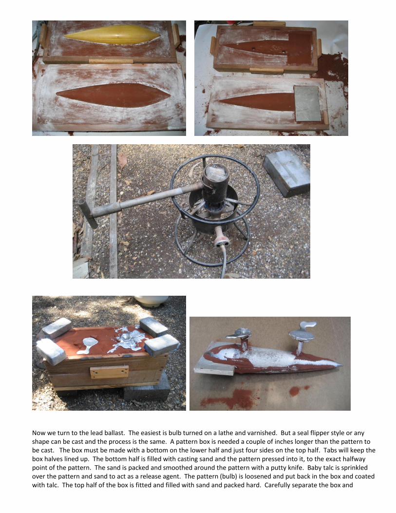
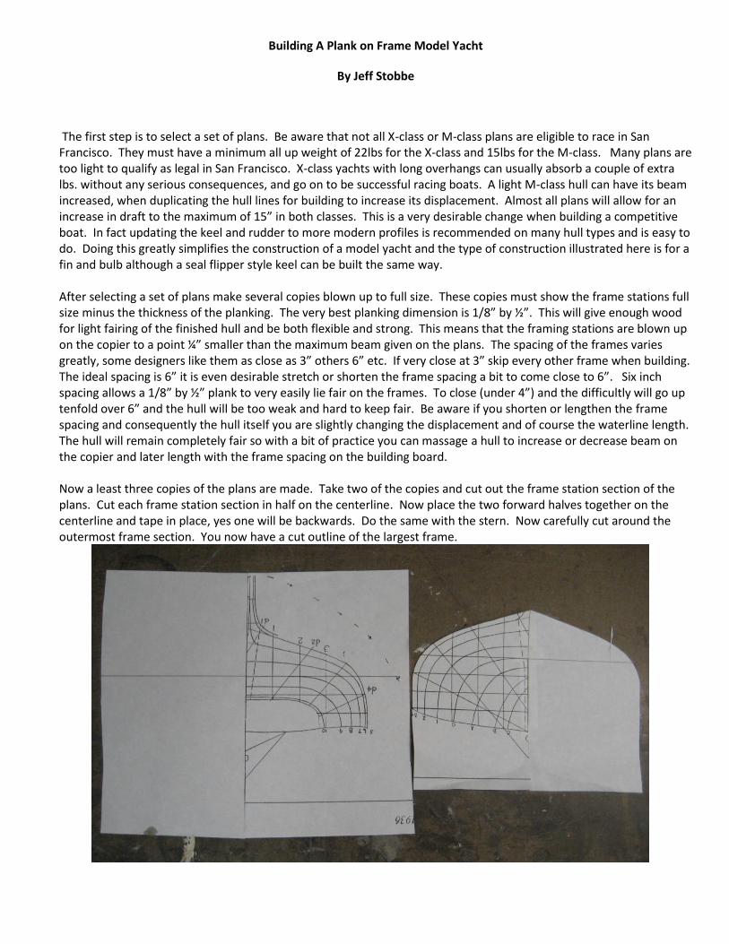
Now we turn to the lead ballast. The easiest is bulb turned on a lathe and varnished. But a seal flipper style or any shape can be cast and the process is the same. A pattern box is needed a couple of inches longer than the pattern to be cast. The box must be made with a bottom on the lower half and just four sides on the top half. Tabs will keep the box halves lined up. The bottom half is filled with casting sand and the pattern pressed into it, to the exact halfway point of the pattern. The sand is packed and smoothed around the pattern with a putty knife. Baby talc is sprinkled over the pattern and sand to act as a release agent. The pattern (bulb) is loosened and put back in the box and coated with talc. The top half of the box is fitted and filled with sand and packed hard. Carefully separate the box and

remove the bulb. Using a putty knife carve out a rectangle for a ½” aluminum plate to fit in, one half the plates thickness in each half of the box. The thickness of the plate is the thickness of the keel. The plate will remain in the box during casting to form a slot for the keel to fit in. The lead will not stick to aluminum. Use a ½” drill and by hand make a hole thru the sand in the upper half if the box at the high point of the bulb to pour the lead in and another to let the air out. Any stove top or propane burner can melt the lead. When melted stir and skim the slag off the top with a large spoon before pouring. The mold is weighted to prevent the top from floating . After cooling knock the aluminum plate out with a hammer. Trim the flashing with the band saw.


Smooth the lead bulb, filing and sanding and a little bondo then paint with a primer for easier handling. Wear a dust mask and wash your hands when handling lead. Drill some ¼” holes 3/8” deep inside the slot in the bulb and at the back of the slot to create a mechanical bond for the epoxy. Likewise drill some holes in the bottom of the fin keel. Using a line between the fin and skeg align the bulb for and aft. It must be straight or it will act like a rudder. Tape up the bottom of the bulb to seal it and pour in the epoxy very slowly to allow the air to escape from the holes you have drilled in the bulb and fin. A little bondo and sanding and your yacht is ready for paint and varnish.