Embed Size (px)
Citation preview

Appendix V – Building Automation to the UConn Design Standards
Page 1 of 31 Revised July 2016
Building Automation Systems Standards
Office of University Planning, Design and Construction
And Facilities Operations and Building Services
Established Date: May 2015 ‐ Revised
Appendix V – Building Automation to the UConn Design Standards
Page 2 of 31 Revised July 2016
1 OverviewThe intent of this document is to outline the site specific requirements to facilitate the complete
installation of a Building Automation System (BAS) which addresses the needs of multiple stakeholders
on campus. The Facilities Operations team requires standardized system platforms and applications.
The Designer is responsible for identifying in detail the design of alterations to an existing system or new
system for competitive pricing.
1.1 SubmissionRequirementsShop Drawings
Shop drawing submittals must include a communication riser “system architecture” diagram depicting
locations of all controllers and workstations, with associated Intra‐Building network wiring.
Operating and Maintenance Manuals (O&M) O&M shall contain all information necessary for the operation, maintenance, replacement, installation,
and parts procurement for the entire BAS. This documentation shall include specific part numbers and
software versions and dates. A complete recommended spare part inventory list shall be included with
the lead time and expected frequency of use of each part clearly identified.
Color Graphic Slides
For each system or floor plan, the color graphic display shall contain the associated points identified in
the point list and allow for set point changes as required and as standardized by the University. For the
purpose of testing and ongoing commissioning, summary graphic pages shall display all unitary and zone
controls (such as VAV boxes) in a text only format. The summary graphics shall list in real time the point
values from space temperature, temperature set point, airflow minimum and maximum set point, actual
CFM, valve and damper position, etc.
Software Documentation
As‐built software documentation shall include the following:
Descriptive point lists
Application program listing
Operation and Maintenance Manuals for all equipment
Application programs with comments
Printouts of all reports
Alarm list
Printouts of all graphics
Point to Point Checkout
Data Backup
At completion of the project, a data/database backup of all programming and graphic files shall be
provided to the University both on the server and on diskettes.
Quality Assurance
Appendix V – Building Automation to the UConn Design Standards
Page 3 of 31 Revised July 2016
The Designer shall require as part of any bid involving new system, impacts to existing or replacement of
a Building Automation System, that the bidder must identify what system is included in their bid, who
the subcontractor is for the Installation and programing of the Building Automation System and their
certification as an accepted installer by the manufacturer of that system. Other installer qualifications
shall include the following:
The Installer must be an authorized distributor of the manufacturer.
The Installer must be in the business of installing building automation systems for at least 5
years.
The Installer must have capabilities of doing component level repairs on electronic systems.
The Installer must have personnel dedicated to application software generation.
The Installer shall have the necessary facilities and personnel to provide training and service of
the system.
Fiber optic cable shall only be installed and terminated by an experienced contractor.
The installer must demonstrate their ability to respond to emergency repair service inclusive of 24
hours/day, seven days/week for the period of specified warranty period. Third party service or service
only during specific working hours is not acceptable.
The equipment and software proposed by the supplier shall be currently manufactured and supported.
All hardware and software must fully compatible with each other, and must be approved by the Building
Automation System manufacturer. No custom products shall be allowed.
2 ProductsofaBuildingAutomationSystemBAS controller manufacturers should not be mixed within a building. If renovating a building, utilize the
same manufacturer of the existing system in the building. Exceptions may apply for specialized
laboratory environments or for lighting control.
Building Automation Systems software platform shall be either Andover Controls Continuum program or
Automated Logic Corporation.
Laboratory room pressure and fume hood controls shall be manufactured by either Phoenix or
Accuspec’s Accuvalve. The laboratory controls shall be similar to the Phoenix MIX 400 or 500 Series.
The University recognizes control dampers manufactured by Tamco as the quality standard we expect.
Designer shall provide a minimum of two other comparable manufacturers of control dampers for the
University to review prior to including into the specifications. Sole source of control dampers is
prohibited.
The University recognizes control valves manufactured by either Belimo, Flow Control or HCI as the
quality standard we expect.

Appendix V – Building Automation to the UConn Design Standards
Page 4 of 31 Revised July 2016
The Designer must include a note that the Contractor must coordinate between the BAS contractor’s
scope of work and the electrical and mechanical contractors to clearly delineate the roles and
responsibilities of each party.
The Designer shall require that the BAS contractor to provide field supervision and verification of proper
installations of the following:
Automatic control dampers
Fire/smoke dampers
Pressure and Differential pressure transmitters
Airflow and water flow measuring stations
Blank‐off plates for dampers that are smaller than the duct size
Sheet metal baffle plates to eliminate stratification
3 BASRequirementsExcept as otherwise noted, the control system shall consist of all Ethernet Network Controllers (ECU),
Standalone Digital Control Units, workstations, software, sensors, transducers, relays, valves, dampers,
damper operators, PE and EP switches, control panels, dryer, filter drains, air pressure reducing stations,
compressed air supply piping and other accessory equipment, along with a complete system of electrical
interlocking wiring and pneumatic piping to fill the intent of the specification and provide for a complete
and operable system. Except as otherwise specified, provide operators for equipment such as dampers if
they are not provided with the equipment.
The Designer, not the building automation systems contractor, is responsible for estimating the cost of
the system and coordinating the construction documents. Ensure that the equipment and system
operation is fully coordinated within the construction documents, verify quantities and types of
dampers, operators, alarms, etc. to be provided. Any discrepancies between contract documents, the
greater quantity and better quality shall take precedence.
All low voltage control or interlock wiring (120VAC or less) and installation of control devices associated
with the equipment list shall be provided under the Mechanical contractor. When the BAS system is fully
installed and operational, the Mechanical contractor in conjunction with the BAS contractor will review
and verify the system functions with the Engineer of Record and University Representative in
accordance with the drawings and specifications. Require that the Contractor provide services and
manpower necessary for commissioning of the system.
3.1 SupportforOpenSystemsProtocolsThe BAS system design must include solutions for the integration of the following "open systems"
protocols: BacNet, ModBus, OPC and digital data communication to third party microprocessors such as
chiller controllers, fire panels and variable frequency drives (vfds).
Appendix V – Building Automation to the UConn Design Standards
Page 5 of 31 Revised July 2016
All buildings shall be provided with the appropriate hardware to establish a BacNet communication
gateway to the Campus for the University’s future use to facilitate either a standardized third‐party
alarm mapping station, graphics workstations, historian data server or other platforms. BAS shall be
provided with the capability of integrating all point data from within the building to third‐party devices
or external systems via BacNet/IP protocol without having to purchase additional equipment, software
or software licenses.
The system shall also provide the ability to program custom ASCII communication drivers that will reside
in the NCU, for communication to third‐party systems and devices. These drivers will provide real time
monitoring and control of the third party systems.
3.2 BASControllerHardwareRequirementsHardware Override Switches: All digital output units shall include three position manual override
switches to allow selection of the ON, OFF, or AUTO output state. These switches shall be built into the
unit and shall provide feedback to the controller so that the position of the override switch can be
obtained through software. In addition, each analog output shall be equipped with an override
potentiometer to allow manual adjustment of the analog output signal over its full range, when the 3
position manual override switch is placed in the ON position.
Local Status Indicator Lamps
Provide as a minimum LED indication of CPU status, Ethernet LAN status, and field bus status. For each
output, provide LED indication of the value of the output (On/Off). For each output module provide an
LED which gives a visual indication of whether any outputs on the module are manually overridden.
Automatic Restart after Power Failure
Upon restoration of power after an outage, the ECU shall automatically and without human
intervention: update all monitored functions; resume operation based on current, synchronized time
and status, and implement special start‐up strategies as required.
Battery backup
Each Network Control Unit (“NCU”) with the standard 120‐220VAC power supply shall include a
programmable DC power backup system rated for a minimum of 72 hours of battery backup to maintain
all volatile memory or, a minimum of 2 hours of full UPS including modem power. This power backup
system shall be configurable such that at the end of a settable timeframe (such as 1 hour) of running on
full UPS, the unit will shut off full UPS and switch to memory retention‐only mode for the remainder of
the battery power. The system shall allow the simple addition of more batteries to extend the above
minimum battery backup times.
3.3 BASSoftwareRequirementsThe NCU shall contain flash ROM as the resident operating system. Application software will be RAM
resident. Application software will only be limited by the amount of RAM memory. There will be no
restrictions placed on the type of application programs in the system. Each NCU shall be capable of
parallel processing, executing all control programs simultaneously. Any program may affect the

Appendix V – Building Automation to the UConn Design Standards
Page 6 of 31 Revised July 2016
operation of any other program. Each program shall have the full access of all I/O facilities of the
processor. This execution of control function shall not be interrupted due to normal user
communications including interrogation, program entry, printout of the program for storage, etc.
3.4 StandaloneDigitalControlUnits(SDCUs)Standalone Digital Control Units shall provide control of HVAC and lighting. Each controller shall have its
own control programs and will continue to operate in the event of a failure or communication loss to its
associated NCU.
Communication Ports
SDCUs shall provide a communication port to the field bus. In addition, a port shall be provided for
connection of a portable service tool to support local commissioning and parameter changes with or
without the NCU online. It shall be possible from a service port on any SDCU to view, enable/disable,
and modify values of any point or program on any controller on the local field bus, any NCU or any SDCU
on a different field bus.
Input/Output
Each SDCU shall support the addition of the following types of inputs and outputs:
Digital Inputs for status/alarm contacts
Counter Inputs for summing pulses from meters
Thermistor Inputs for measuring temperatures in space, ducts and thermowells
Analog inputs for pressure, humidity, flow and position measurements
Networking
Each SDCU will be able to exchange information on a peer to peer basis with other Standalone Digital
Control Units during each field bus scan. Each SDCU shall be capable of storing and referencing global
variables (on the LAN) with or without any workstations online. Each SDCU shall be able to have its
program viewed and/or enabled/disabled either locally through a portable service tool or through a
workstation connected to an NCU.
Indicator Lamps
SDCUs will have as a minimum, LED indication of CPU status, and field bus status,
Real Time Clock (RTC)
An SDCU shall have a real time clock in either hardware or software. The accuracy shall be within 10
seconds per day. The RTC shall provide the following information: time of day, day, month, year, and day
of week. Each SDCU shall receive a signal, every hour, over the network from the NCU, which
synchronizes all SDCU real time clocks.
Automatic Restart after Power Failure
Upon restoration of power, the SDCU shall automatically and without human intervention, update all
monitored functions, resume operation based on current, synchronized time and status, and implement
special start‐up strategies as required.

Appendix V – Building Automation to the UConn Design Standards
Page 7 of 31 Revised July 2016
Battery Back Up
Each SDCU shall have at least 3 years of battery back up to maintain all volatile memory.
3.5 AirHandlerControllersAn LCD display shall be optionally available for readout of point values and to allow operators to change
setpoints and system parameters.
A manual override switch shall be provided for all digital and analog outputs on the AHU Controller. The
position of the switch shall be monitored in software and available for operator displays and alarm
notification.
3.6 VAVTerminalUnitControllersVAV Controllers for single duct applications will come equipped with a built‐in actuator for modulation
of the air damper. The actuator shall have a minimum torque rating of 35 in.‐lb., and contain an override
mechanism for manual positioning of the damper during startup and service.
3.7 OperatorWorkstationRequirementsThe BAS workstation software shall be configurable as either a single workstation system (with a local
database) or multi‐workstation system where the database is located on a central file server. The client
software on multi‐workstation system shall access the file server database program via an Ethernet
TCP/IP network running at either 10MBPS or 100MBPS.
A minimum of one (1) operator workstation should be located and installed in each building (excluding
dormitory facilities or buildings comprised of less than 20,000 Square Feet). All workstations shall
communicate with the central Campus automation server via Ethernet.
All workstation operating systems and hardware specifications shall meet or exceed the minimum
software requirements and recommendations as documented from the building automation system
manufacturer.
The application software shall be capable of communication to all NCUs and SDCUs, feature high‐
resolution color graphics, alarming, reporting, and be user configurable for all data collection and data
presentation functions.
For multi‐workstation systems, a minimum of 256 workstations shall be allowed on the Ethernet
network along with the central file server. In this client/server configuration, any changes or additions
made from one workstation will automatically appear on all other workstations without the
requirement for manual copying of files. Multi‐workstation systems with no central database will not be
acceptable. Multi‐workstation systems with distributed/tiered file servers and a central (master)
database will be acceptable.
3.8 ColorGraphicDisplaysThe system shall allow for the creation of user‐defined, color graphic displays for the viewing of
mechanical and electrical systems, or building schematics. These graphics shall contain point
information from the database including any attributes associated with the point (engineering units,
Appendix V – Building Automation to the UConn Design Standards
Page 8 of 31 Revised July 2016
etc.). In addition, operators shall be able to command equipment or change set points from a graphic
through the use of the mouse. The Contractor shall submit for review during the course of installation
the systems graphics and software for review and comments. System graphics and software will be
made available at 50%, 75%, and 90% completion. System will not be deemed complete until reviewed
and accepted by the University's representative. Requirements of the color graphic subsystem include
the following:
SVGA, bit‐mapped displays. The user shall have the ability to import AutoCAD generated picture
files as background displays.
A built‐in library of animated objects such as dampers, fans, pumps, buttons, knobs, gauges, ad
graphs which can be "dropped" on a graphic through the use of a software configuration
"wizard". These objects shall enable operators to interact with the graphic displays in a manner
that mimics their mechanical equivalents found on field installed control panels. Using the
mouse, operators shall be able to adjust set points, start or stop equipment, modify PID loop
parameters, or change schedules.
Status changes or alarm conditions must be able to be highlighted by objects changing screen
location, size, color, and text, blinking or changing from one display to another.
Graphic panel objects shall be able to be configured with multiple "tabbed" pages allowing an
operator to quickly view individual graphics of equipment, which make up a subsystem or
system.
Ability to link graphic displays through user defined objects, alarm testing, or the result of a
mathematical expression. Operators must be able to change from one graphic to another by
selecting an object with a mouse ‐ no menus will be required.
3.9 AlarmManagementIndividual alarms shall be able to be re‐routable to a workstation or workstations at user‐specified times
and dates. For example, a critical high temp alarm can be configured to be routed to a Facilities Dept.
Workstation during normal working hours (7am‐6pm, Mon‐Fri) and to a Central Alarming workstation at
all other times.
3.10 SchedulingThe BAS shall have the ability to configure and download from the workstation schedules for any of the
controllers on the network.
Occupancy schedules should be configured per the software standards. Schedules shall be configured to
group equipment by building (standard) or by AHU or floor (for larger buildings). Individual equipment
schedules shall only be configured by exception to meet a specific space need.
3.11 Programmer'sEnvironmentAll systems shall be provided with the necessary program editing software so that system configuration
modifications and changes to application preprograming, graphics, alarm configurations, user security,
etc can be performed by the University’s trained representative without requiring the contractor to
return to the site.

Appendix V – Building Automation to the UConn Design Standards
Page 9 of 31 Revised July 2016
Source graphic files shall be provided to the University if the files are needed to make modifications to
the system graphics.
3.12 DataLoggingThe workstation software shall have the capability to easily configure groups of data points with trend
logs and display the trend log data. The trend log data shall be displayed through a simply menu
selection. This data shall be able to be saved to file and/or printed.
Standard Logging – Hardwired inputs should be logged at an interval of 15 minutes for a minimum of 96
samples (24 Hours)
Short Term Logging – For the purpose of commissioning control loops, it is required to specify short‐
term trending for certain key components (i.e. duct static pressure, VFD speed, etc) at 1 minute intervals
for a 2‐hours duration (120 samples). This may require the creation of redundant mirrored software
points to achieve both standard logging and short term logging for the same point.
Extended Logging – Long term historical data should be downloaded to the server for key input and
output points which are indicative of overall system performance (Vfd Speed, meter data, energy data,
etc.). Long‐term data shall be maintained on the server for a minimum of 13 months.
3.13 AuditTrailThe workstation software shall automatically log and timestamp every operation that a user performs at
a workstation, from logging on and off a workstation to changing a point value, modifying a program,
enabling/disabling an object, viewing a graphic display, running a report, modifying a schedule, etc.
3.14 DDCSensorsandPointHardwareTemperature Sensors: Standard space sensors shall be available in an off white enclosure for mounting
on a standard electrical box. Where manual overrides are required, the sensor housing shall feature
both an optional sliding mechanisms for adjusting the space temperature set point, as well as a push
button for selecting after hour's operation. Where a local display is specified, the sensor shall
incorporate either an LED or LCD display for viewing the space temperature, set point and other
operator selectable parameters. Using built in buttons, operators shall be able to adjust set points
directly from the sensor.
Occupancy Sensors
The University utilizes space occupancy sensors for HVAC control where the application of such sensors
provides a reasonable simple payback period of approximately 4 years or less. Examples of a typical
application are high occupant dense spaces such as auditoriums, classrooms, and seminar rooms,
gymnasiums, larger conference spaces, laboratories, etc. Occupancy Sensors may be installed for HVAC‐
only purposes or integrated with the local space lighting control, where appropriate. When occupancy
sensors are integrated with the local space lighting control, the occupancy sensor shall continue to
Appendix V – Building Automation to the UConn Design Standards
Page 10 of 31 Revised July 2016
monitor the space occupancy when the lighting wall switch or other lighting control is turned to the off
position.
Humidity Sensors
Humidity sensors shall be provided as required by the sequence of operation and shall be accurate up to
3 % RH.
Pressure Sensors
Space pressure sensors must be selected with the appropriate range to provide both adequate
resolution accuracy and display range of the controlled variable.
Air pressure measurements in the range of 0 to 10" water column will be accurate to +/‐1%
using a solid‐state sensing element. Acceptable manufacturers include Modus Instruments and
Mamac.
Differential pressure measurements of liquids or gases shall be accurate to 0.5% of range. The
housing shall be NEMA 4 rated.
Current and KW Sensors
Current status switches shall be used to monitor fans, pumps, motors and electrical loads. Current
switches shall be available in solid and split core models, and offer either a digital or an analog signal to
the automation system. Acceptable manufacturer is Veris or approved equal.
Measurement of three‐phase power shall be accomplished with a kW/kWh transducer. This device shall
utilize direct current transformer inputs to calculate the instantaneous value (kW) and a pulsed output
proportional to the energy usage (kWh). Provide Veris Model 6000 Power Transducer or approved
equal.
Instrumentation
BAS Contractor shall be responsible for control wiring and integration of all meters, liquid and steam
flow sensors and utility monitoring points to the BAS to meet any requirements outlined in the sequence
of operations.
Flow Sensors
Provide for measurement of liquid, gas or steam flows in pipe sizes above 3 inches. Install the flow
meter on an isolation valve to permit removal without process shutdown. Sensors shall be
manufactured by EMCO or approved equal.
3.15 AutomatedControlValvesProvide automatic control valves suitable for the specified controlled media (steam, water or glycol).
Provide valves, which mate and match the material of the connected piping. Equip control valves with
the actuators of required input power type and control signal type to accurately position the flow
control element and provide sufficient force to achieve required leakage specification.

Appendix V – Building Automation to the UConn Design Standards
Page 11 of 31 Revised July 2016
Control valves shall meet the heating and cooling loads specified, and close off against the differential
pressure conditions within the application. Valves should be sized to operate accurately and with
stability from 10 to 100% of the maximum design flow.
Trim material shall be stainless steel for steam and high differential pressure applications.
Steam control valves used for modulating applications larger than 1‐1/4 pipe size shall utilize multiple
valves in 1/3 & 2/3 tandem arrangement to limit wear on the valve seats.
Electric actuation should be provided on all terminal unit reheat applications.
Control valves for use in perimeter radiation applications shall accept an analog input signal and shall be
capable of modulating over the entire range of the valve. Two position, floating and tri‐state actuators
are not acceptable for radiant perimeter heating of occupied spaces.
3.16 AutomaticControlDampersExtruded aluminum damper frame shall not be less than 0.080” (2.03 mm) in thickness. Welded frames
shall not be acceptable.
Blades shall be maximum 6.4" (162.6 mm) deep extruded aluminum air‐foil profiles with a minimum
wall thickness of 0.06” (1.52mm).
Hexagonal control shaft shall be 7/16" (11.11 mm). It shall have an adjustable length and shall be an
integral part of the blade axle. A field‐applied control shaft shall not be acceptable. All parts shall be
zinc‐plated steel.
Dampers shall be custom made to required size, with blade stops not exceeding 1¼” (31.7 mm) in height
and designed for operation in temperatures ranging from ‐40°F (‐40°C) to 212°F (100°C).
Dampers shall be opposed blade or parallel blade action, as indicated on the plans.
Installation of dampers must be in accordance with manufacturer’s current installation guidelines.
Automated Control Valve and Damper Actuators
All actuators shall be electric driven. Pneumatic actuators are not acceptable. Tristate or floating
actuators will not be accepted except for VAV terminal damper control applications.
3.17 CO2SensorsCO2 sensors may be required to be located in the return duct or in the occupied spaces to achieve the
requirements outlined in the sequence of operation.
DCV sequence of operation shall be compliant with ASHRAE 62.1‐2004 standard for air quality while
maximizing energy savings. Outside air damper leakage rates should be factored into the control
strategy.

Appendix V – Building Automation to the UConn Design Standards
Page 12 of 31 Revised July 2016
CO2 sensors shall a) Provide accuracy of ±30 ppm ±2% of measured value, b) Operate in measured range
of 0‐2000 ppm, and c) Provide repeatability of ±20 ppm ±1% of measured value
3.18 AirflowMeasuringStationsFor low flow velocity applications (less than 500 fpm) an Ebtron airflow monitoring station shall be
utilized.
3.19 AirflowMeasuringStations(FanorDuctApplications)For normal flow velocity applications (greater than 500 fpm) an airflow probe by Air Monitor or TSI shall
be utilized.
4 EXECUTION4.1 WiringandConduitInstallationThe 120VAC power wiring to each Ethernet or Remote Site controller shall be a dedicated run, with a
separate breaker. Each run will include a separate hot, neutral and ground wire. The ground wire will
terminate at the breaker panel ground. This circuit will not feed any other circuit or device.
Conduit in finished areas will be concealed in ceiling cavity spaces, plenums, furred spaces and wall
construction. For masonry walls, metallic surface raceways maybe used. All surface raceway in finished
areas must be color matched to the existing finish within the limitations of standard manufactured
colors.
Wiring is to be kept a minimum of six (6) inches from hot water, steam, or condensate piping. Where
sensor wires leave the conduit system, they are to be protected by a plastic insert.
Control air tubing shall be run concealed wherever possible, properly supported, and installed in a neat
and workmanlike manner. Piping drooped across building structure or laid on ceiling will not be
permitted. Tubing may be run exposed in occupied areas only with written approval of the University.
Copper or plastic tubing where allowed to be run exposed to view in finished areas shall be run in two ‐
piece metal surface raceway.
4.2 InstallationPracticesforFieldDevicesWell‐mounted sensors will include thermal conducting compound within the well to insure good heat
transfer to the sensor.
Actuators will be firmly mounted to give positive movement and linkage will be adjusted to give smooth
continuous movement throughout 100 percent of the stroke.
Relay outputs will include transient suppression across all coils. Suppression devices shall limit transients
to 150% of the rated coil voltage.
Water line mounted sensors shall be removable without shutting down the system in which they are
installed. For duct static pressure sensors, the high‐pressure port shall be connected to a metal static
Appendix V – Building Automation to the UConn Design Standards
Page 13 of 31 Revised July 2016
pressure probe inserted into the duct. The low pressure port shall be left open to reference the open
area where the transmitter is installed.
For building static pressure sensors, the high‐pressure port shall be inserted into the space via a metal
tube. Pipe the low‐pressure port to the exterior of the building.
4.3 EnclosuresFor all I/O requiring field interface devices, these devices where practical will be mounted in a field
interface panel (FIP). The Contractor shall provide an enclosure, which protects the device(s) from dust,
moisture, conceals integral wiring and moving parts.
Field panels shall contain power supplies for sensors, interface relays and contractors, safety circuits,
and I/P transducers.
The FIP enclosure shall be of steel construction with baked enamel finish, NEMA1 rated with a hinged
door and keyed lock. The enclosure will be sized for twenty percent spare mounting space. All locks will
be keyed identically.
All wiring to and from the FIP will be to screw type terminals. Analog or communications wiring may use
the FIP as a raceway without terminating. The use of wire nuts within the FIP is prohibited.
All outside mounted enclosures shall meet the NEMA‐4 rating.
Tubing and wiring within all enclosures shall be run in plastic track. Wiring within controllers shall be
wrapped and secured.
4.4 ComponentIdentificationIdentify all control wires with labeling tape or sleeves using either words, letters, or numbers that can be
exactly cross‐referenced with as‐built drawings.
Identify all pneumatic tubing with labeling tape or sleeves using either words, letters, or numbers that
can be exactly cross referenced with as‐built drawings.
All field enclosures, other than controllers, shall be identified with a backlit or engraved nameplate. The
lettering shall be in white against a black or blue background.
Junction box covers will be marked to indicate that they are a part of the BAS system.
All I/O field devices (except space sensors) that are not mounted within field panels shall be identified
with name plates.
All I/O field devices inside FIP's shall be labeled.
Appendix V – Building Automation to the UConn Design Standards
Page 14 of 31 Revised July 2016
4.5 ExistingControlsExisting controls, which are to be reused, must each be tested and calibrated for proper operation.
Existing controls, which are to be reused and are found to be defective requiring replacement, shall be
noted to the University.
4.6 LocationThe location of sensors shall be coordinated with the mechanical, electrical and architectural drawings.
Space humidity or temperature sensors will be mounted away from machinery generating heat, direct
light and diffuser air streams.
Outdoor air sensors will be mounted on the north building face directly in the outside air. Install these
sensors such that the effects of heat radiated from the building or sunlight is minimized.
Field enclosures shall be located immediately adjacent to the controller panel(s) to which it is being
interfaced.
4.7 TrainingThe BAS Contractor shall provide both on‐site and classroom training to the University's representative
and maintenance personnel. A minimum of two days of training shall be provided, and all training shall
be done by personnel with administrator level factory experience.
4.8 WarrantyThe system shall be warranted for a minimum of 12 months (labor and material) and five (5) years on all
material after system acceptance and beneficial use by the University, including all necessary revisions
to the software as required to provide a complete and workable system.
Updates to the manufacturer's software shall be provided at no charge during the warranty period.
4.9 MeasurementandVerificationRequirementsWhen identified as part of the LEED certification for a project, the BAS contractor shall provide the
controls and monitoring on all measurement and verification devices.
4.10 ControllerandWorkstationCheckoutProvide a field checkout equipment and system for all controllers and front‐end equipment (computers,
printers, modems, etc.). The BAS contractor shall verify proper operation of both hardware and
software of all system components. A checkout sheet shall be provided itemizing each device and a
description of the associated tests shall be prepared and submitted to the University representative at
the completion of the project.
4.11 SystemStartup&CommissioningEach point in the system shall be tested for both hardware and software functionality. In addition, each
mechanical and electrical system under control of the BAS will be tested against the appropriate
sequence of operation specified herein. A written report will be submitted to the University indicating
that the installed system functions in accordance with the plans and specifications.

Appendix V – Building Automation to the UConn Design Standards
Page 15 of 31 Revised July 2016
The BAS contractor shall commission in operating condition all major equipment and systems, such as
the chilled water, hot water and all air handling systems, in the presence of the equipment
manufacturer's representatives, and the University’s and Architect's representatives.
Occupancy sensors shall require a trend report with a minimum of 48 hours for each sensor input,
showing the occupancy patterns of the space upon project completion.
4.12 SystemAcceptanceTestingAll application software will be verified and compared against the sequences of operation. Control loops
will be exercised by inducing a set point shift of at least 10% and observing whether the system
successfully returns the process variable to set point. Record all test results and attach to the Test
Results Sheet.
Test each alarm in the system and validate that the system generates the appropriate alarm message,
that the message appears at all prescribed destinations (workstations or printers), and that any other
related actions occur as defined (i.e. Graphic panels are invoked, reports are generated, etc.). Submit a
Test Results Sheet to the University representative.
Perform an operational test of each unique graphic display and report to verify that the item exists, that
the appearance and content are correct, and that any special features work as intended. Submit a Test
Results Sheet to the University representative.
Perform an operational test of each third party interface that has been included as part of the
automation system. Verify that all points are properly polled, that alarms have been configured, and
that any associated graphics and reports have been completed. If the interface involves a file transfer
over Ethernet, test any logic that controls the transmission of the file, and verify the content of the
specified information.
4.13 PointnamingconventionEach point shall be clearly identifiable by viewing its point name. If a controller is unique to an area and
its name is viewable to the operator, then it is not necessary to be redundant with the point name. As
an example, if the Controller name was Rm122, then the point can be named Space Temperature,
otherwise the point name should read “Rm122_SpaceTemp.
Room numbering that is shown on the design documents should be followed, except the BAS contractor
should confirm same with the University prior to naming all points and controllers.
5 SequenceofOperation
5.1 VAVwith/withoutReheatand/orRadiationMinimum Temperature Set points for VAV Terminals
All VAV terminal boxes capable of both heating and cooling shall be programmed with a minimum of 5
temperature set points as follows:
Appendix V – Building Automation to the UConn Design Standards
Page 16 of 31 Revised July 2016
Unoccupied Cooling Set point (Default 82 °F)
Occupied Cooling Set point (1.5° above Default 73.5 °F)
Base Room Set point (Default 72 °F)
Occupied Heating Set point (1.5° below Room Set point: Default 70.5 °F)
Unoccupied Heating Set point (Default 60 °F)
Additional Temperature Set points for Classrooms and Large Conference spaces
In addition to the set points above large spaces that are equipped with occupancy sensors shall also
have the following set points:
Relaxed Cooling Set point (4° above Base Room Set point Default 76 °F)
Relaxed Heating Set point (4° below Base Room Set point: Default 68 °F)
All VAV terminal boxes furnished with reheat coils shall be furnished with a reheat coil discharge air
temperature sensor. Reheat coil leaving air temperature shall be limited to a maximum leaving air
temperature of 90 °F (adj.) when terminal unit is in a call for full heating.
Radiant heating valves shall be provided with an analog output signal (4‐20 mA or 2‐10 VDC) floating or
tri‐state valves are not acceptable.
Optimal Start/ Morning Warmup/Cool down Mode
All Vav terminal units shall be programmed to operate with an optimal start mode, morning warmup
and morning cool down sequences that are programmed at the air handler.
Night Mode
All Vav Terminals shall be programmed with a night mode that will activate the air handler when the
unoccupied temperature set points have been exceeded.
Occupancy Sensors
Medium size spaces designed for between 3 and 12 occupants shall be equipped with dual technology
occupancy sensors that will be used to lower ventilation rates and relax the space temperatures when
the space is unoccupied.
Thermostats
Except in common areas such as hallways and lobbies, all thermostats shall be equipped with a
pushbutton override feature.
Demand Control Ventilation
Large capacity spaces (example: classrooms, large conference rooms) designed for more than 12
occupants shall be equipped with CO2 sensors for monitoring and resetting the minimum ventilation
rates in the space. Very large spaces (example: large classrooms, auditoriums, cafeterias) designed for
more than 20 occupants shall be equipped with both CO2 sensors and occupancy sensors. The default
CO2 set point for the campus is 900 ppm or approx. 600 ppm above the outside air CO2 level.
Appendix V – Building Automation to the UConn Design Standards
Page 17 of 31 Revised July 2016
The default period of occupancy for all schedules shall be programmed as follows unless indicated
otherwise:
Dormitory and Living Quarters ‐ Always Occupied
Academic and Classroom Spaces ‐ Monday thru Friday 7 AM to 10 PM, occupied
Weekends and Holidays = unoccupied
Offices and All Other Space Types ‐ Monday thru Friday 7 AM to 6 PM, occupied
Weekends and Holidays = unoccupied
Holiday List ‐ New Year’s Day
Memorial Day
Independence Day
Thanksgiving
Christmas
Occupied Period Temperature Control Sequence – Vav Terminal
The occupancy schedule shall be set for all VAV boxes within the building from the front‐end
workstation. All mechanical spaces shall be set for 24 hr. occupancy. Constant volume boxes shall
maintain a constant airflow and the DDC controller shall monitor airflow and modulate the supply box
damper to maintain a constant airflow set point.
Variable volume boxes shall maintain a variable airflow based on a call for heating or cooling from the
room temperature sensor. On a demand for cooling, the variable volume box shall modulate towards its
maximum flow set point. As the room temperature nears its set point, the reverse shall occur.
On a demand for heat as sensed by the space temperature sensor, the variable volume box shall
modulate towards its minimum flow set point. Upon a further call for heat (if reheat is applicable), the 2‐
way reheat valve shall modulate to maintain the space temperature heating set point (plus or minus the
slide adjustment). If baseboard radiation is available, the variable volume box shall modulate towards its
minimum flow set point, the reheat valve shall be modulated to 100% followed by the radiation valve.
The reheat coil leaving air temperature shall be limited to a maximum of 90 °F. If a full call for heat is
reached and the space requires additional heat capacity, the Vav terminal damper shall modulate open
to provide additional airflow. The maximum heating setpoint shall be limited to the midpoint using the
following formula; MaxHeatCFM = ((MaxCFM – MinCFM) X 50%) + MinCFM)
The room sensors for all offices shall have a temperature adjustment slider that will allow personnel to
make set point adjustments to the space (+/‐ 2 °F.) There will be no slide adjustment or override
capability for the mechanical spaces or common area hallways and corridors.
Unoccupied Period Temperature Control Sequence – Vav Terminal
During unoccupied mode, as scheduled from the workstation, the room set point for heating shall be
60°F and the cooling set point shall be 82°F. During the unoccupied mode, the VAV box shall modulate

Appendix V – Building Automation to the UConn Design Standards
Page 18 of 31 Revised July 2016
100% open when the Night Set‐Up set point reaches 82°F. As the room temperature drops three
degrees below the Night Set‐Up set point the VAV/CV box shall modulate closed. A Night Set‐back mode
with a set point of 60°F shall modulate the radiation valve open 100%. If there is no radiation available,
the reheat valve shall modulate to 100% open and the VAV/CV shall go to its minimum CFM set point. As
the room temperature rises three degrees above the Night Set‐back set point the reheat valve or
radiation valve shall be modulated closed and the VAV/CV damper shall close. If VAV/CV box is
commanded off by the schedule, the VAV Supply and Exhaust Box dampers modulate closed, the reheat
valve, and radiation valve shall also modulate closed. A push‐button switch shall be provided with the
room sensor (except mechanical spaces), which shall provide a 180 minute (adjustable via the DDC
workstation) temporary occupancy during the unoccupied period.
Morning Warmup Mode
The optimal start sequence, morning warm‐up and morning cool‐down functions and decision sequence
shall be done within the air handler. * Lines 2, 3 and 4 do not apply to VAV boxes served by gas fired
heating units, which may maintain a fixed minimum airflow at the air handler. The VAV terminal shall
monitor the air handler leaving air temperature. When the AHU leaving air temperature is above the
Vav’s space temperature by more than 1 °F, the AHU is assumed to be operating in the warmup mode.
The Vav damper shall switch to reverse acting mode when the AHU’s discharge air is above the space
temperature by more than 1 °F to avoid overheating of the space. The damper shall return to the
normal direct acting when the space temperature falls to 1 °F below the AHU leaving air temperature.
When the damper is operating in reverse acting mode, the minimum VAV box cfm set point shall be set
to 0 CFM.
Temperature Control Sequence – VAV Terminal w/ Occupancy Sensor
During the occupied period, the occupancy schedule shall be set for all VAV boxes within the building
from the front‐end workstation. All mechanical spaces shall be set for 24 hr. occupancy.
Constant volume boxes shall maintain a constant airflow and the DDC controller shall monitor airflow
and modulate the supply box damper to maintain a constant airflow set point. Variable volume boxes
shall maintain a variable airflow based on a call for heating or cooling from the room temperature
sensor.
On a demand for cooling, the variable volume box shall modulate towards its maximum flow set point.
As the room temperature nears its set point, the reverse shall occur. On a demand for heat as sensed by
the space temperature sensor, the variable volume box shall modulate towards its minimum flow set
point. Upon a further call for heat (if reheat is applicable), the 2‐way reheat valve shall modulate to
maintain the space temperature heating set point (plus or minus the slide adjustment).
If baseboard radiation is available, the variable volume box shall modulate towards its minimum flow set
point, the reheat valve shall be modulated to 100% followed by the radiation valve.

Appendix V – Building Automation to the UConn Design Standards
Page 19 of 31 Revised July 2016
The reheat coil leaving air temperature shall be limited to a maximum of 90 °F. If a full call for heat is
reached and the space requires additional heat capacity, the Vav terminal damper shall modulate open
to provide additional airflow. The maximum heating setpoint shall be limited to the midpoint using the
following formula; MaxHeatCFM = ((MaxCFM – MinCFM/2) + MinCFM)
The room sensors for all offices shall have a temperature adjustment slider that will allow personnel to
make set point adjustments to the space (+/‐ 2 °F.) There will be no slide adjustment or override
capability for the mechanical spaces or common area hallways and corridors.
“Relaxed” Mode
When the space is occupied per the occupancy schedule but the occupancy sensors detect that no
occupants are in the space, the relaxed mode of operation shall be set. The heating and cooling
temperature set points shall be relaxed by 2.5 °F each (4 °F from base set point.} The minimum CFM set
point shall be 0 CFM unless ventilation is required to provide heating or cooling needed to meet the
relaxed temperature set points.
When the space occupancy sensor detects someone in the space the relaxed mode shall terminate and
the normal mode of operation shall resume. If the occupancy schedule is turned off, the Vav terminal
shall revert to the unoccupied sequence.
Unoccupied Mode
During unoccupied mode, as scheduled from the workstation, the room set point for heating shall be
60°F and the cooling set point shall be 82°F. During the unoccupied mode, the VAV box shall modulate
100% open when the Night Set‐Up set point reaches 82°F. As the room temperature drops three
degrees below the Night Set‐Up set point the VAV/CV box shall modulate closed. A Night Set‐back mode
with a set point of 60°F shall modulate the radiation valve open 100%. If there is no radiation available,
the reheat valve shall modulate to 100% open and the VAV/CV shall go to its minimum CFM set point. As
the room temperature rises three degrees above the Night Set‐back set point the reheat valve or
radiation valve shall be modulated closed and the VAV/CV damper shall close. If VAV/CV box is
commanded off by the schedule, the VAV Supply and Exhaust Box dampers modulate closed, the reheat
valve, and radiation valve shall also modulate closed. A push‐button switch shall be provided with the
room sensor (except mechanical spaces), which shall provide a 180 minute (adjustable via the DDC
workstation) temporary occupancy during the unoccupied period.
If the occupancy sensor detects someone preset in the space during the unoccupied mode, the Vav
terminal shall then operate in the occupied mode of operation for a minimum of 15 minutes until the
occupancy sensor indicates that the space is unoccupied.
Morning Warmup Mode
The optimal start sequence, morning warm‐up and morning cool‐down functions and decision sequence
shall be done within the air handler. * Lines 2, 3 and 4 do not apply to VAV boxes service by gas fired
heating units which may maintain a fixed minimum airflow at the air handler.

Appendix V – Building Automation to the UConn Design Standards
Page 20 of 31 Revised July 2016
The VAV terminal shall monitor the air handler leaving air temperature. When the AHU leaving air
temperature is above the Vav’s space temperature by more than 1 °F, the AHU is assumed to be
operating in the warmup mode. The Vav damper shall switch to reverse acting mode when the AHU’s
discharge air is above the space temperature by more than 1 °F to avoid overheating of the space. The
damper shall return to the normal direct acting when the space temperature falls to 1 °F below the AHU
leaving air temperature. When the damper is operating in reverse acting mode, the minimum VAV box
cfm set point shall be set to 0 CFM.
Temperature Control Sequence – VAV Terminal w/ CO2 Sensor
The CO2 sensor shall reset the minimum CFM set point between 0 and the maximum CFM set point as
required to maintain the CO2 set point of 900 ppm (adj). If heating or cooling is required to maintain
the space temperature set points, the Vav terminal minimum CFM set point shall control to the higher
signal. (CO2 vs heating/cooling.)
Exhaust Terminal Boxes
The Exhaust boxes shall work in conjunction with then associated supply box to maintain the required
differential CFM offset in the space.
VAV Terminal Radiation Valve Sequence
The radiation valve shall be fully closed (lockout) when the outside air temperature is below 50 °F.
When the outside air temperature falls below the lockout set point of 50 °F (adj.) the radiation valve
shall be enabled.
The radiation valve shall maintain a minimum valve set point position that will be proportionately reset
as follows:
When the reheat valve or heating signal reaches 50% open, the radiation valve will begin to open further
and will continue to modulate open (using a 2‐1 ratio with the reheat valve) until the room heating set
point is reached.
Standard Variable Air Volume AHU Sequence
The Air Handling Units are variable air volume units serving terminal units throughout the building. Each
unit consists of dual supply fans with airflow monitoring stations at each fan. Minimum outdoor air
ventilation shall be provided by indirect measurement of outdoor air by subtracting the measured
return air volume from the measured supply air volume.
Start/Stop Control
The air handler shall run on an occupied/unoccupied schedule (user adjustable) as required to satisfy
the duct static pressure set point (See Fan speed control below). On a call to start, associated exhaust
fans will be energized, the unit's return smoke damper shall be opened, and exhaust, return and outside
Outside Air Temperature Minimum Valve Position
50 °F 0% Open
5 °F 25% Open

Appendix V – Building Automation to the UConn Design Standards
Page 21 of 31 Revised July 2016
air damper section shall modulate to maintain the mixed air temperature set point. Once the end switch
on the smoke damper indicates that it is open, the return fans shall be started, and the supply fan
smoke damper energized. When the supply smoke damper end switch indicates that it is open, the
supply fans shall start. On a shutdown, the smoke dampers will not be closed until the appropriate
supply or return fan status indicates that the fan has stopped.
Optimized Start Time, Morning Warm‐up and Cool‐down Modes
During the unoccupied mode of operation, the air handler shall monitor the average space temperature
by calculating the average of each space temperature sensors served by the AHU. The AHU shall
calculate the time required to bring the average space temperature to the occupied set points of 71 °F
heating (adj) and 74 °F cooling (adj.) prior to the occupied start time. The calculation shall factor the
rate of temperature change °/hr calculated from the prior day.
Morning warm‐up – The AHU shall utilize a morning warm‐up cycle when the optimal start time
sequence determines that the space is below the occupied heating set point. The morning
warm‐up sequence will set the AHU leaving air temperature to 80 DegF and the outside air
dampers shall remain closed.
Morning cool‐down ‐ The AHU shall utilize a morning cool down cycle when the optimal start
time sequence determines that the space is above the occupied cooling set point. The morning
cools down sequence will set the AHU leaving air temperature to 55 DegF and the outside air
dampers shall remain closed unless the economizer cooling mode is enabled.
Supply Fan Speed Control ‐ Upon start‐up of the Air Handling Unit, as sensed by the supply fan
current sensor, and following a 30 second delay (adjustable), the two supply fans will begin to
ramp up slowly together. During operation, the supply fan speed control signals (to both drives)
will modulate to maintain system duct static pressure set point of 1.0” W.C. (adj.) as sensed by
the remote supply air static pressure sensor. Supply fan header static pressure shall function as
a high limit set to 2.5” W.C., overriding normal supply fan speed modulation under certain
conditions. The supply fan speed control signals will be indexed to zero percent (0%) speed
during safety shutdown and normal unoccupied shutdown.
During unoccupied periods, the lag supply fan shall be shut down, if the supply fan speeds fall
below 30% for more than 2 minutes. If only one supply fan is running and the supply fan speeds
exceed 95% then the lag fan shall be started. A minimum off‐time of 3 minutes must elapse
before a supply fan can be restarted.
Return Fan Speed Control ‐ Upon start‐up as sensed by the return fan current sensor and
following a 30 second delay (adjustable), the return fan speed will begin to ramp up slowly.
During operation, the return fan speed control signal will modulate to maintain a constant
differential between supply and return flow volumes. Return fan inlet static pressure will
operate as a limit to override fan speed control under certain conditions. The return fan speed

Appendix V – Building Automation to the UConn Design Standards
Page 22 of 31 Revised July 2016
control signal will be indexed to zero percent (0%) speed during safety shutdown and normal
unoccupied shutdown.
Mixed Air Damper Control
Upon start‐up as sensed by the supply fan current sensor, the outdoor air damper shall modulate to
maintain mixed air temperature set point. Set point will be based on an offset from supply air
temperature set point. Appropriate offset shall be determined based upon the average heat gain across
the fan section.
Economizer control shall be enabled when the outside air enthalpy is 2 btu/lb lower than return air
enthalpy. When the economizer is on, the outdoor air damper shall modulate to maintain set point
between 100% open and the minimum outdoor air set point (adjustable). As the outdoor air damper
opens, the return air dampers will close proportionally. When the economizer mode is off, the outdoor
air damper will close to the minimum outdoor air set point (adjustable).
The outdoor air damper will fully close and the return air dampers will fully open during unoccupied
mode and upon shutdown.
Preheat Coil Control (Hot Water Coil)
Upon start‐up as sensed by the supply fan current sensor, the preheat valve shall modulate based on the
unit discharge temperature sensor and the unit discharge set point. When the system is operating in a
warm‐up mode, the preheat coil valve shall remain open to the coil. The preheat valve will fully open
during a safety shutdown. The preheat valve will modulate to maintain a 55 DegF set point at the
preheat coil sensor when the units is shut down. The preheat valve shall be locked out (closed) at all
times when the outside air temperature is more than 55 DegF.
Chilled Water Valve
Upon start‐up as sensed by the supply fan current sensor, the chilled water valve will modulate based on
the discharge air temperature set point. The chilled water valve will not open either when the preheat
valve is open or the system is operating in warm‐up mode. The chilled water valve will fully open during
a safety shutdown. The chilled water valve will fully close during normal unoccupied shutdown. The
chilled water valve shall be locked out (closed) at all times when the outside air temperature is less than
55 DegF unless there is a freezestat trip condition.
Discharge Air Set Point Reset Control
The discharge air temperature set point will be reset based on the state of the terminal units served by
the air handling unit. In an open loop fashion, the discharge air set point will be reset upward until at
least one terminal unit is operating at close to full cooling. Set point shall be step increased in 0.5 degree
increments over 5 minute periods and shall always be maintained between 55 and 60 degrees.
Freeze Conditions
A low limit thermostat, hardwired to the fan shall de‐energize the fan on detection of a temperature
drop to 38 degrees. Manual reset at the unit is required.

Appendix V – Building Automation to the UConn Design Standards
Page 23 of 31 Revised July 2016
Steam Humidifier
When the supply fan is operating as indicated by the current sensor, the steam humidifier valve shall
modulate to maintain a return air relative humidity set point of 35% RH (adj.). The supply air humidity
sensor shall also be monitored and the valve shall limit the supply air humidity to the limit set point of
80% RH (adj.). The steam humidifier shall be disabled when the chilled water valve is not completely
closed or when the air handler is commanded off.
5.2 100%OutsideAirAHUSequenceforLaboratoryAreasSupply Air Temperature Control Sequence
The AHU leaving air temperature set point shall be set to 55 DegF at all times for all load conditions.
When the preheat valves are open and in use, the chilled water control valve shall be locked out to
prevent simultaneous heating and cooling. When the chilled water valve is in operation, the preheat
valves shall be locked out.
Supply Air Duct Static Control Sequence
The AHU shall run continuously (24/7/365) and the supply fan VFD speed/s shall modulate to maintain
the duct static set point.
Preheat Control Sequence (Steam Coil w/ Face Bypass Damper)
When the preheat steam line is larger than 1‐1/4” in diameter, a 1/3 – 2/3 tandem steam control valve
arrangement shall be used to limit wear and “grooving” on the control valve seats. Upon loss of power,
the 1/3 valve shall fail open, the 2/3 steam valve shall fail closed. When the AHU is shut off, the preheat
valves shall close. The 1/3 valve shall modulate open if the AHU casing temperature falls below 50 DegF.
When the Outside Air temperature rises above 52°F, the Pre‐heat valves shall remain closed and the
face bypass damper shall remain in full bypass.
Stage 1 preheat ‐ When the Outside air temperature drops below 52°F (adj.), the 1/3 preheat steam
valve shall modulate full open, the 2/3 preheat steam valve shall remain closed and the Face and By‐
pass damper shall modulate to maintain the supply air temperature set point of 55°F.
Stage 2 preheat‐ When the Outside Air Temperature drops below 30 °F (adj.) or the discharge air
temperature drops below 50 DegF, the 2/3 preheat steam valve shall modulate full open, the 1/3
preheat steam valve shall remain closed and the Face and By‐pass damper shall modulate to maintain
the supply air temperature set point of 55°F. If the supply air temperature exceeds 58 DegF for more
than 1 minute, the sequence shall revert to Stage 1.
Stage 3 preheat ‐ When the Outside Air Temperature drops below 10 °F (adj.) or the discharge air
temperature drops below 45 DegF, both the 1/3 and 2/3 preheat steam valves shall be full open and the
Face and By‐pass damper shall modulate to maintain the supply air temperature set point of 55°F. If the
supply air temperature exceeds 58 DegF for more than 1 minute, the sequence shall revert to Stage 2.
Upon a freezestat safety trip, the 1/3 valve shall go to the full open position and the 2/3 valve shall go to
the full closed position until the safety alarm has cleared.
Appendix V – Building Automation to the UConn Design Standards
Page 24 of 31 Revised July 2016
Preheat Control Sequence (Hot Water Coil)
Upon loss of power, the hot water valve shall fail open. When the AHU is shut off, the preheat valve
shall close. The valve shall modulate open if the AHU casing temperature falls below 50 °F. When the
Outside Air temperature rises above 52°F, the Pre‐heat valve shall remain closed. When the Outside air
temperature drops below 52°F (adj.), the preheat valve shall modulate to maintain the supply air
temperature set point of 55°F. Upon a freezestat safety trip, the valve shall go to the full open position
until the safety alarm has cleared.
Chilled Water Valve Control Sequence
Upon loss of power, the chilled water valve shall fail closed. When the AHU is shut off, the chilled valve
shall close. When the Outside Air temperature falls below 54°F, the chilled water valve shall remain
closed. When the Outside air temperature rises above 54°F (adj.), the chilled water valve shall modulate
to maintain the supply air temperature set point of 55°F. Upon a freezestat safety trip, the valve shall go
to the full open position until the safety alarm has cleared.
5.3 LaboratoryManifoldExhaustFanSequenceSettings and set points
VFD set point
Set to maintain the minimum fan motor speed (typically 15 Hz) Actual set point determined by motor
manufacturer.
Stack velocity VFD set point
The minimum fan VFD speed required to maintain the minimum stack air velocity discharged from the
exhaust fan. Actual minimum airflow set point determined by mechanical engineer / Engineer of record
and shall be confirmed with the air balancer.
Duct Static set point
The set point is to be set by the air balancer to achieve the deign airflows at all terminal units under full
load conditions.
Duct low‐pressure static safety device set point
To be set based on the design rating of the ductwork. Actual set point determined by mechanical
engineer / Engineer of record.
Lead Fan Startup Sequence
One fan unit shall run continuously, the units shall be run in a lead/lag/back‐up fashion and the lead fan
will automatically be rotated monthly. The following shall happen when the first unit is started via the
DDC panel, with the fan isolation dampers closed the fan shall start and run at its minimum speed of 15
Hz, after the fan has stated the fan isolation damper shall then open to 100%, when the damper end
switch is proven open, the exhaust fan shall begin ramping up from its minimum speed set point to
maintain the duct static set point of 2.0 “ W.C. (adj.) The DDC system shall modulate the exhaust fan
drive to control to the low select of two static pressure sensors located at the plenum. Each exhaust fan
status shall be monitored from a current transmitter located at the respective VFD.
Appendix V – Building Automation to the UConn Design Standards
Page 25 of 31 Revised July 2016
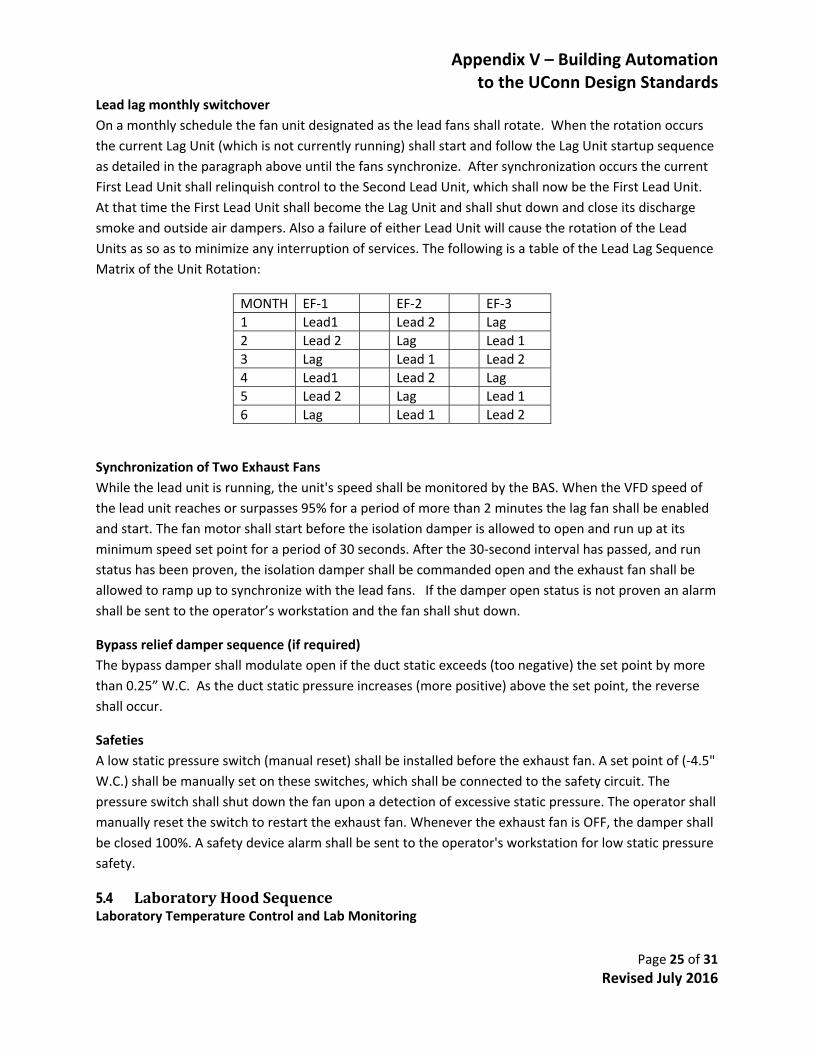
Lead lag monthly switchover
On a monthly schedule the fan unit designated as the lead fans shall rotate. When the rotation occurs
the current Lag Unit (which is not currently running) shall start and follow the Lag Unit startup sequence
as detailed in the paragraph above until the fans synchronize. After synchronization occurs the current
First Lead Unit shall relinquish control to the Second Lead Unit, which shall now be the First Lead Unit.
At that time the First Lead Unit shall become the Lag Unit and shall shut down and close its discharge
smoke and outside air dampers. Also a failure of either Lead Unit will cause the rotation of the Lead
Units as so as to minimize any interruption of services. The following is a table of the Lead Lag Sequence
Matrix of the Unit Rotation:
MONTH EF‐1 EF‐2 EF‐3
1 Lead1 Lead 2 Lag
2 Lead 2 Lag Lead 1
3 Lag Lead 1 Lead 2
4 Lead1 Lead 2 Lag
5 Lead 2 Lag Lead 1
6 Lag Lead 1 Lead 2
Synchronization of Two Exhaust Fans
While the lead unit is running, the unit's speed shall be monitored by the BAS. When the VFD speed of
the lead unit reaches or surpasses 95% for a period of more than 2 minutes the lag fan shall be enabled
and start. The fan motor shall start before the isolation damper is allowed to open and run up at its
minimum speed set point for a period of 30 seconds. After the 30‐second interval has passed, and run
status has been proven, the isolation damper shall be commanded open and the exhaust fan shall be
allowed to ramp up to synchronize with the lead fans. If the damper open status is not proven an alarm
shall be sent to the operator’s workstation and the fan shall shut down.
Bypass relief damper sequence (if required)
The bypass damper shall modulate open if the duct static exceeds (too negative) the set point by more
than 0.25” W.C. As the duct static pressure increases (more positive) above the set point, the reverse
shall occur.
Safeties
A low static pressure switch (manual reset) shall be installed before the exhaust fan. A set point of (‐4.5"
W.C.) shall be manually set on these switches, which shall be connected to the safety circuit. The
pressure switch shall shut down the fan upon a detection of excessive static pressure. The operator shall
manually reset the switch to restart the exhaust fan. Whenever the exhaust fan is OFF, the damper shall
be closed 100%. A safety device alarm shall be sent to the operator's workstation for low static pressure
safety.
5.4 LaboratoryHoodSequenceLaboratory Temperature Control and Lab Monitoring

Appendix V – Building Automation to the UConn Design Standards
Page 26 of 31 Revised July 2016
All Laboratories shall have a 24 hour occupied schedule located in the CX controller. The Phoenix supply
air valves with reheat coils shall have a discharge air temperature sensor in the discharge duct for
monitoring. The room sensors for the labs shall have an adjustment slider that will allow personnel to
make set point adjustments to the space (+/‐ 1.5 Degrees °F). On a demand for heat as sensed by the
space temperature sensor, the 2‐way reheat valve shall modulate to maintain the space temperature set
point of 72 Degrees F. (plus the slide adjustment).
The control panel shall control the supply and hood exhaust air valves to maintain a minimum of 6 air
changes per hour while maintaining the minimum FPM across each fume hood sash and constant supply
/ exhaust differential.
Only for lab (524/527), which has a General Exhaust Valve, Andover Controls shall have the ability to
override the exhaust and modulate the Thermal Demand on a call cooling, the reheat coil valves shall be
closed. An output signal (0‐10V) shall be provided to the mix card, which will make the Phoenix Supply
valve and the General Exhaust valves modulate open to satisfy the desired room temperature set point
(user adjustable). The opposite shall occur when Thermal Demand is off.
Controller cards shall have the following specified output signals monitored through the Andover
Controls panel. The following signals shall be picked up as provided by the laboratory controls:
Supply / Make‐up Flow (CFM)
Total Exhaust Flow (CFM)
Individual Fume Hood Exhaust Flow (CFM)
Individual Fume Hood Exhaust Flow Alarm (On = Alarm)
Individual Fume Hood Sash Position (% Open)
Thermal Demand Override Output (%Open)
General Exhaust Flow (CFM)
5.5 FanCoilUnitApplicationsSequenceFCU with/without Heating and/or Radiation
Temperature Set points: All fan coil units capable of both heating and cooling shall be programmed with
a minimum of 5 temperature set points as follows:
Unoccupied Cooling Set point (Default 82 °F)
Occupied Cooling Set point (2° above Default 74 °F)
Base Room Set point (Default 72 °F)
Occupied Heating Set point (2° below Room Set point: Default 70 °F)
Unoccupied Heating Set point (Default 60 °F)
Temperature Control (Occupied Period): All fan coil units shall have a start/stop schedule based on the
occupancy schedule at the front‐end workstation and all mechanical spaces shall have a 24 hr occupied
period. The fan coil chilled water and hot water valves (4‐pipe application) shall be modulated based on
the room temperature set points (72°F +/‐ Slide Adjustment) as sensed by the room temperature
sensor. The room sensors shall have a temperature adjustment slider that will allow personnel to make
Appendix V – Building Automation to the UConn Design Standards
Page 27 of 31 Revised July 2016
set point adjustments to the space (+/‐ 2 °F). Units that have convector radiation shall modulate the
radiation control valve to maintain room heating set point. If the space is not satisfied and the radiation
valve is 100% open, the fan coil's heating valve shall begin to modulate towards 100% open to satisfy the
space.
Temperature Control (Unoccupied Period): During unoccupied mode, as scheduled from the front‐end
workstation, the room set point for Night Setback shall be 60°F and the set point for Night Set‐Up shall
be 82°F (adj.). During the unoccupied mode, the fan coil unit shall be commanded on and shall
modulate the chilled water valve 100% open when the space temperature rises above the Night Set‐Up
set point (82°F adj.). As the room temperature drops three degrees below the Night Set‐Up set point
the chilled water valve shall close and the fan coil unit shall be commanded off. A Night Set‐back mode
with a set point of 60°F (adj.) shall modulate the radiation valve open 100% (if applicable) or modulate
the heating valve open 100% and command the fan coil unit on. As the room temperature rises three
degrees above the Night Set‐back set point, the radiation or the heating valve shall modulate closed and
the fan coil unit shall be commanded off. A current switch shall monitor fan coil unit's status. If the unit
is commanded off, the heating and cooling valves shall close.
A push‐button at the stat shall be provided with the room sensor, which shall provide a 3 hour
(adjustable via the DDC workstation) temporary occupancy override during the unoccupied period.
There will be no slide adjustment or override capability for the mechanical spaces.
5.6 EconomizerAHUApplicationsSequenceECONOMIZERSupply Fan/ Return Fan Control
Start‐up
The air handler shall run on an occupied/unoccupied schedule (user adjustable.) The DDC system shall
monitor the supply & return fan status via current sensor. On a command to start the supply smoke
damper shall open and upon being proven open by its end switch, the supply fan shall start. The return
fan shall be allowed to start when the supply fan current sensor has proven the supply fan on. Both fans
shall start at their minimum speed as supplied by manufacturer’s representative. After 30 seconds
running at their minimum speed, the fans shall then slowly ramp up to the desired set points.
Shut‐Down
Upon a command to shutdown, both fans shall ramp down to their minimum speed as supplied by
manufacturer’s representative. After running for 10 seconds at the minimum speed the fans shall then
shut off and the smoke damper/s shall close.
Supply Air Volume Control
The supply fan speed shall modulate the VSD to maintain a main duct static pressure of 1.0" WC
(starting point to be set by balancer). The supply and return fan air volumes shall be measured via
airflow stations at the unit. The return fan will track the supply flow minus a given offset set point.
(Adjustable) The design engineer shall determine the starting offset set point.
Occupancy Schedules

Appendix V – Building Automation to the UConn Design Standards
Page 28 of 31 Revised July 2016
The default period of occupancy for all occupancy schedules shall be programmed as follows unless
indicated otherwise:
Dormitory and Living Quarters
Always Occupied
Academic and Classroom Spaces:
o Monday thru Friday 7 AM to 10 PM
o Weekends and Holidays = Unoccupied
Offices and All Other Space Types
o Monday thru Friday 7 AM to 6 PM
o Weekends and Holidays = Unoccupied
Mixed Air Damper Control
Economizer Mode
If the Outside Air Enthalpy is lower than the Return Air Enthalpy by more than 2 Btu/lb, as calculated via
the building Outside Air temperature and humidity sensors and the Return Air temperature and
humidity sensors, the unit shall be placed in Economizer mode. The Outside Air and Exhaust dampers
shall be allowed to modulate towards 100% open and the Return Air damper shall modulate towards
the closed position to maintain the Mixed Air set point of 52°F (user adjustable).
Economizer Lockout Mode
If the Outside Air Enthalpy is above the Return Air Enthalpy, the Outside Air damper and Exhaust Air
damper shall modulate towards the Minimum set position (15% open for starting point, adjustable via
balancer readings) and the Return Air damper shall modulate towards the open position. If the C02
sensor rises above the 900‐PPM limit, the Outside Air CFM reset schedule shall be allowed to supersede
the Economizer Lockout Mode to satisfy the C02 sensor requirements as defined in the above "C02 CFM
Control" section.
5.7 EconomizerAHUwithCO2ControlApplicationSequenceSupply/Return Fan Control
The air handler shall run on an occupied/unoccupied schedule supplied by UConn (user adjustable). The
DDC system shall monitor the supply & return fan status via current sensor. On a command to start the
supply smoke damper shall open and upon being proven open by its end switch, the supply fan shall
start. The return fan shall be allowed to start when the supply fan current sensor has proven the supply
fan on. Both fans shall start at their minimum speed as supplied by manufacturer’s representative and
slowly ramp up to the desired speed set points.
Supply Volume Control
The supply fan speed shall modulate the VSD to maintain a main duct static pressure of 1" WC (user
adjustable starting point). The supply and return fan air volumes shall be measured via airflow stations
at the unit. The return fan will track the supply flow minus a given offset set point. (Adjustable) The
design engineer shall determine the starting offset set point.

Appendix V – Building Automation to the UConn Design Standards
Page 29 of 31 Revised July 2016
Mixed Air Control ‐ Economizer Mode
If the Outside Air Enthalpy is lower than the Return Air Enthalpy by more than 2 btu/lb., as calculated via
the building Outside Air temperature and humidity sensors and the Return Ah temperature and
humidity sensors, the unit shall be placed in Economizer mode. The Outside Air and Exhaust dampers
shall be allowed to modulate towards 100% open and the Return Air damper shall modulate towards
the closed position to maintain the Mixed Air set point of 52°F (user adjustable).
C02 CFM Control
Please note that an Outside Air Flow Station at the outdoor air intake is needed to complete C02
control. Alternatively, return air flow station/s and supply fan flow station/s may be used to indirectly
measure the outside air volume.
The Outside Air CFM requirements dictated by the Return Air C02 sensor will take priority over the
mixed air temperature set point. A minimum volume set point of Outside Air shall be maintained per the
ASHRAE 62‐1 standard to satisfy the building area when the space is occupied. As the C02 levels rise
above 900 PPM in the Return Air, the Outside Air CFM requirements of the unit shall be reset upwards
from the minimum set point to the maximum outside air damper percentage. If the mixed air
temperature falls below 55 °F, then the OA/RA dampers shall modulate to allow less outside air.
Economizer Lockout Mode
If the Outside Air Enthalpy is above the Return Air Enthalpy, the Outside Air damper and Exhaust Air
damper shall operate at the Minimum damper position.
The outside air damper position shall be set as follows:
Units with CO2 control – Outside air minimum damper position shall be equal to the ASHRAE
62.1 table of prescribed airflow of CFM per sq. ft. for the area served by the AHU. If the C02
sensor rises above the 900‐PPM limit, the Outside Air CFM reset schedule shall be allowed to
supersede the Economizer Lockout Mode to satisfy the C02 sensor requirements as defined in
the above "C02 CFM Control" section.
Units without CO2 control
Outside air minimum damper position shall be set to achieve 15% of outside air flow (relative to
the total supply air flow) as measured by the air balancer or to achieve the prescribed minimum
airflow quantity provided by the engineer.
Supply Air Temperature and Preheat Control w/FB Damper
Outside Air Temperature >= 40 °F and <=68°F
The supply air temperature sensor, as sensed through the DDC system, shall modulate the pre‐heat
steam valve and the cooling coil valve in sequence to maintain a supply air temperature of 55°F (user
adjustable). The Face and By‐pass damper shall be open to full face and shall not modulate.
Outside Air Temperature < 40 °F

Appendix V – Building Automation to the UConn Design Standards
Page 30 of 31 Revised July 2016
When the outside air temperature drops below 40°F, the preheat steam valve shall modulate full open
and the Face and By‐pass damper shall modulate to maintain the supply air temperature set point of
55°F.
Outside Air Temperature > 68°F
When the outside air temperature rises above 68°F, the Pre‐heat valve shall modulate closed and the
cooling valve shall modulate to maintain the supply temperature set point of 55°F. The Face and By‐
pass Damper shall be closed (0% Open) allowing full bypass of the preheat coil.
Unoccupied Control
When the Air Handler is commanded off via the schedule, the supply fan VFD shall be commanded off
and fan shall ramp down to 0% Speed. The return fan VFD shall also be commanded off and shall ramp
down to 0% Speed. The chilled water valve will modulate closed. However, if the Freeze Stat trips, the
chilled water valve shall open 100%. The Pre‐Heat Steam valves shall modulate to maintain a 50°F case
temperature as sensed by the pre‐heat discharge temperature sensor. The Outside Air dampers and
Exhaust dampers shall modulate to and remain closed (0% Open) and the Return dampers shall
modulate to and remain at 100% open.
Safeties
Freeze Control
An averaging‐type temperature sensor shall monitor the air leaving the preheat coil. A critical alarm
shall be sent to the DDC workstation if the temperature drops below 40 °F or if the freeze stat trips. If a
freeze stat trip occurs, the outside and exhaust air dampers shall close and the return air damper shall
open. The supply fan, which is hardwired to the freeze stat shall stop and the return fan shall also stop
via a software interlock. The chilled water valve shall open 100% under any freeze stat trip. The pre‐heat
steam valve shall then modulate to maintain a 50°F case temperature as sensed by the pre‐heat
discharge temperature sensor.
Smoke Alarm Control
Duct smoke detectors located at the discharge of the unit shall shut off both supply and return fans if
activated. The unit smoke detectors shall be interlocked to the fan starters to shut down both fans.
5.8 ExhaustFanApplicationsSequenceofEventsMechanical or Electrical Room Ventilation (Start/Stop Applications Only)
The exhaust fan shall operate anytime the respective room space temperature sensor is above its set
point of 80°F (Adj.). When the temperature is above the set point the fans shall be commanded to start
and their respective dampers (Intake and/or Discharge) shall be energized open. Once the end switches
prove open, the fans shall be energized on. When the temperature drops 2°F below the set point, the
fan shall be commanded off and the respective dampers shall close. An alarm shall be sent to the
operations workstation in the event of an exhaust fan failure. An alarm shall be sent to the operations
workstation should the room temperature sensor rise 5°F above set point.
Appendix V – Building Automation to the UConn Design Standards
Page 31 of 31 Revised July 2016
5.9 SteamtoHotWaterConverterSequenceThe heat exchanger shall be controlled with modulating 1/3 – 2/3 steam valves to minimize excessive
wear or “grooving” on the valve seats which is likely to result from modulating steam. The valves shall
modulate to maintain a leaving water temperature of 180°F. The valves shall be sequenced in a manner
to minimize the periods that the control valve is operating in the 0 to 20% open range.
The steam valves shall be staged based on load conditions as follows:
o Stage 1: Modulate 1/3 valve & close 2/3 valve
o Stage 2: Modulate 2/3 valve & close 1/3 valve
o Stage 3: Lock open 1/3 valve & modulate 2/3 valve
o Stage 4: Lock open 2/3 valve & modulate 1/3 valve
5.10 StandardHeatRecoverSystemApplicationsSequenceHeat Recovery System for 100% outside air AHU
The heat recovery pumps 1 & 2 shall run in a lead/lag fashion with the lead pump alternated weekly.
The pumps shall only run when the outside air temperature is greater than 82°F or the outside air temp
is less than 52°F. Each heat recovery coil located at the exhaust fans, shall be allowed to run only when
its associated exhaust fan is running. When not in operation the coil's 3‐way by‐pass valves shall close to
the system, bypassing the heat recovery coil. When the heating season is "On", the AHU pre‐heat valve
shall modulate to maintain the supply air set point. If a further demand for heating is required, the heat
recovery valves at the exhaust fans shall begin to modulate open to maintain the set point from the AHU
with the lowest discharge temperature. Upon a further demand for heat and after the heat recovery
valves have modulated 100% open, the steam preheat valves shall modulate to maintain their
respective AHU discharge set point.
5.11 StandardLead/LagPumpingSequenceThe system shall operate continuously. Pumps P‐1 and P‐2 shall run in a lead lag fashion, only one pump
shall be running at any time. The lead pump shall be alternated on a monthly basis (@ Noon) by the DDC
system. On a command from the DDC controller, the lag pump shall be energized on and ramped up to
match the speed of the Lead pump. Once the two pump speed outputs are synchronized, the lead pump
shall ramp down, de‐energize off and become the lag pump. A differential pressure transmitter in the
piping loop shall provide an input to the VSD via the DDC system to maintain a minimum system
differential pressure set point of 15 PSID (adj. per design). The differential pressure sensor will be
located per the direction of the design engineer.
The system shall be capable of starting and stopping both pumps. Each pump shall be equipped with a
current sensor for status and an alarm shall be attached to the status point to indicate a pump failure.
The alarm shall be sent to the operations workstation in the event of a pump failure. Upon receiving an
alarm of the lead pump, the lag pump shall start and ramp to maintain the system differential set point.
The failed pump shall be locked out until reset by an operator.