Embed Size (px)
Citation preview

International Journal of Architecture, Engineering and ConstructionVol 8, No 4, December 2019, 29-35
Building Information Modeling for Heating, Ventilation and
Air Conditioning Application
Tushar Jadhav∗
School of Projects, Real Estate, Infrastructure Management, National Institute of Construction Management and Research
Maharashtra, India
Abstract: The increasing use of building information modeling (BIM) amongst architectural, engineering and construction(AEC) industries has created a new paradigm in project management. The coordination of mechanical, electrical and plumbing(MEP) services during construction is often complex and challenging. BIM is nowadays becoming increasingly popular amongstarchitects and engineers as it allows the team to work on a centralized model and each one gets the access to the latest fileversion while working on a particular project. The purpose of this article is to exhibit how BIM is useful in designing ofheating, ventilation and air conditioning (HVAC) system. The paper presents a simple case to highlight the efficacy of usingBIM for HVAC application. The outcomes of this article will help in increasing the confidence of the stakeholders to use BIMfor HVAC application as well as for MEP services.
Keywords: BIM, project management, MEP, HVAC
DOI: http://dx.doi.org/10.7492/IJAEC.2019.026
1 INTRODUCTION
Project management of building services is often a complextask which needs dedicated efforts and smooth coordinationamongst architects, MEP engineers and project managers. Inmost of the cases, blunders are observed during the planningphase of the project. The technological advances and its inte-gration to project management has resulted into the need forusing powerful tools that will ease out the complications indelivering the project within defined cost, quality and time.
Building information modeling (BIM) is one such tool thathelps in effective coordination of complex activities. In thepast, researchers (Migilinskas et al. 2013; Azhar et al. 2015)have attempted to identify the benefits and challenges inimplementation of BIM technology for architectural, engi-neering and construction (AEC) industries Merschbrock andMunkvold (2014) and Korpela and Miettinen (2013) have doc-umented the experiences of architects, engineers and facilitymanagers using BIM for several applications Eastman et al.(2011) have also summarized the lessons learned (in the for-m of case studies) by different stakeholders using BIM acrossall phases of the project. In recent research, Gerges et al.(2019) presented a case on implementation of BIM within theconceptual phase in a construction project.
Planning of heating, ventilating and air conditioning (H-VAC) systems nowadays has become an important activity inproject management due to increasing demand from the clients
in terms of sustainability. This also leads to several revisions inthe system design and selection which further complicates theproject procurement activity. BIM offers an effective solutionas coordination amongst architects, civil and MEP engineersoccurs on a common platform and the changes made by teammembers automatically are reflected in the common drawingused by the project team.Table 1 summarizes the relevant work done by researchers
in HVAC, using BIM.The present paper exhibits how BIM can be useful in the
design process of HVAC system.
2 CASE
The use of BIM for HVAC application is demonstrated withthe help of a simple layout. The purpose behind this is to pro-vide insight to architects and engineers associated with AECcompanies about some critical aspects of HVAC design usingBIM.Figure 1 provides the details of a simple office layout under
study.The major inputs for performing air conditioning load calcu-
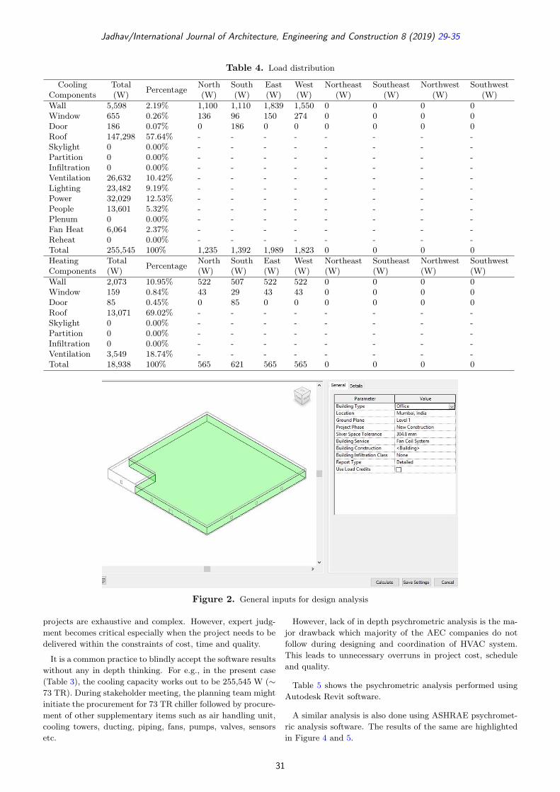
lations includes building envelope, occupancy load, ventilationair requirements, lighting load and equipment load. Figure 2and 3 indicates the general and major details to be furnishedbefore performing the air conditioning analysis using AutodeskRevit software (BIM software).
∗Email: [email protected]
29

Jadhav/International Journal of Architecture, Engineering and Construction 8 (2019) 29-35
Table 1. Relevant work of BIM for HVAC
No. Authors Contribution1. Becerik-Gerber et al. (2011) The authors have explored the use of BIM for facilities management.2. Yang and Ergan (2015) Use of BIM for trouble shooting of HVAC related problems.3. Wang et al. (2016) Developed BIM framework for integrating the MEP layout.4. Motawa and Carter (2013) BIM based model to assist post occupancy evaluation process.5. Cho et al. (2017) Conducted BIM based energy performance assessment.6. Wang et al. (2013) Developed BIM framework for facilities management at design stage.7. Knight et al. (2010) Demonstrated how BIM can be applied in HVAC design.8. Laine et al. (2007) Showed benefits of BIM in thermal performance management.9. Gerrish et al. (2016) Discussed management of building services information using BIM.10. Robert et al. (2014) Described an approach for integrating BIM and energy simulation tools.11. Ren et al. (2016) Showed how BIM can be useful to redefine and enhance the 2D design
for HVAC application.12. Moayeri et al. (2017) Demonstrated the effective use of BIM in design change management
of MEP services.
(a)
(b)
Figure 1. Office layout
The outcomes of the air conditioning load calculations aresummarized in Table 2 to 4.The breakup of components contributing to the cooling and
heating load is summarized in Table 4. This distribution isimportant to understand the critical components contributingtowards the air conditioning energy usage and possible waysto reduce the same. In the present case, the maximum coolingcapacity works out to be 255,545 W (∼ 73 TR) and the heatingcapacity works out to be 18,938 W. The next section discussessome significant considerations that need to be incorporatedwhile working with revit software.
Table 2. Project summary (location and weather)
Project Project-TLocation MumbaiCalculation time Friday, June 7, 2019 1:50 PMReport type DetailedLatitude 18.90◦
Longitude 72.82◦
Summer dry bulb 35◦CSummer wet bulb 28◦CWinter dry bulb 17◦CMean daily range 6◦C
Table 3. Building summary
Building Type OfficeArea (m2) 2,287Volume (m3) 6,860.72Calculated resultsPeak cooling total load (W) 258,406Peak cooling month and hour May 2:00 PMPeak cooling sensible load (W) 229,595Peak cooling latent load (W) 28,810Maximum cooling capacity (W) 255,545Peak cooling airflow (L/s) 15,638.8Peak heating load (W) 18,938Peak heating airflow (L/s) 1,054.0ChecksumsCooling load density (W/m2) 112.99Cooling flow density (L/(s · m2)) 6.84Cooling flow/load (L/(s · kW)) 60.52Cooling area/load (m2/kW) 8.85Heating load density (W/m2) 8.28Heating flow density (L/(s · m2)) 0.46
2.1 Significant Considerations
The common mistakes while working with revit software areaddressed in this section.
2.1.1 Software Vs Expert JudgmentIt is a common debate regarding preference of software or ex-pert advice during HVAC design. It is necessary to understandthat software will ease the overall process especially when the
30
Jadhav/International Journal of Architecture, Engineering and Construction 8 (2019) 29-35
Table 4. Load distribution
CoolingComponents
Total(W) Percentage North
(W)South(W)
East(W)
West(W)
Northeast(W)
Southeast(W)
Northwest(W)
Southwest(W)
Wall 5,598 2.19% 1,100 1,110 1,839 1,550 0 0 0 0Window 655 0.26% 136 96 150 274 0 0 0 0Door 186 0.07% 0 186 0 0 0 0 0 0Roof 147,298 57.64% - - - - - - - -Skylight 0 0.00% - - - - - - - -Partition 0 0.00% - - - - - - - -Infiltration 0 0.00% - - - - - - - -Ventilation 26,632 10.42% - - - - - - - -Lighting 23,482 9.19% - - - - - - - -Power 32,029 12.53% - - - - - - - -People 13,601 5.32% - - - - - - - -Plenum 0 0.00% - - - - - - - -Fan Heat 6,064 2.37% - - - - - - - -Reheat 0 0.00% - - - - - - - -Total 255,545 100% 1,235 1,392 1,989 1,823 0 0 0 0HeatingComponents
Total(W) Percentage North
(W)South(W)
East(W)
West(W)
Northeast(W)
Southeast(W)
Northwest(W)
Southwest(W)
Wall 2,073 10.95% 522 507 522 522 0 0 0 0Window 159 0.84% 43 29 43 43 0 0 0 0Door 85 0.45% 0 85 0 0 0 0 0 0Roof 13,071 69.02% - - - - - - - -Skylight 0 0.00% - - - - - - - -Partition 0 0.00% - - - - - - - -Infiltration 0 0.00% - - - - - - - -Ventilation 3,549 18.74% - - - - - - - -Total 18,938 100% 565 621 565 565 0 0 0 0
Figure 2. General inputs for design analysis
projects are exhaustive and complex. However, expert judg-ment becomes critical especially when the project needs to bedelivered within the constraints of cost, time and quality.
It is a common practice to blindly accept the software resultswithout any in depth thinking. For e.g., in the present case(Table 3), the cooling capacity works out to be 255,545 W (∼73 TR). During stakeholder meeting, the planning team mightinitiate the procurement for 73 TR chiller followed by procure-ment of other supplementary items such as air handling unit,cooling towers, ducting, piping, fans, pumps, valves, sensorsetc.
However, lack of in depth psychrometric analysis is the ma-jor drawback which majority of the AEC companies do notfollow during designing and coordination of HVAC system.This leads to unnecessary overruns in project cost, scheduleand quality.
Table 5 shows the psychrometric analysis performed usingAutodesk Revit software.
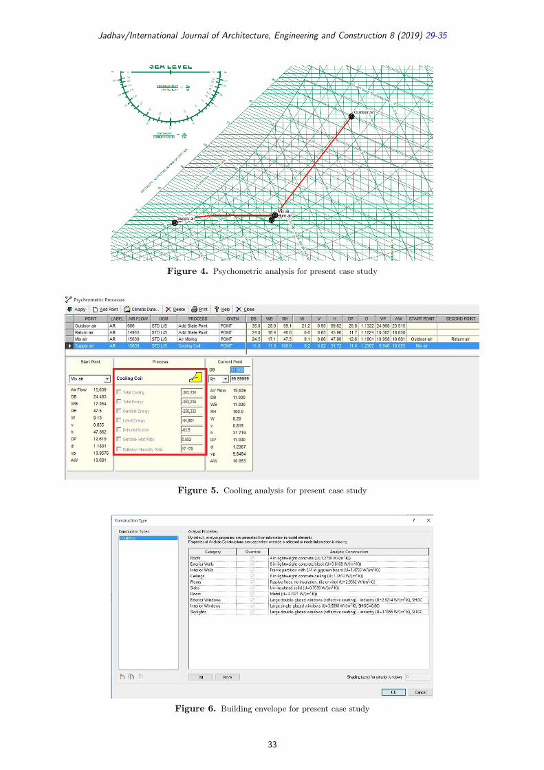
A similar analysis is also done using ASHRAE psychromet-ric analysis software. The results of the same are highlightedin Figure 4 and 5.
31

Jadhav/International Journal of Architecture, Engineering and Construction 8 (2019) 29-35
Figure 3. Major inputs for design analysis
Table 5. Psychrometric analysis using Autodesk Revit
Area (m2) 2,287Volume (m3) 6,860.72Cooling setpoint 24◦CHeating setpoint 21◦CSupply air temperature 12◦CNumber of people 115Infiltration (L/s) 0.0Air volume calculation type Fan Coil SystemRelative humidity 46.00% (Calcu-
lated)PsychrometricsPsychrometric message NoneCooling coil entering dry-bulb tem-perature
25◦C
Cooling coil entering wet-bulb tem-perature
17◦C
Cooling coil leaving dry-bulb tem-perature
11◦C
Cooling coil leaving wet-bulb tem-perature
11◦C
Mixed air dry-bulb temperature 25◦CCalculated resultsPeak cooling total load (W) 255,545Peak cooling month and hour April 2:00 PMPeak cooling sensible load (W) 231,604Peak cooling latent load (W) 23,941Peak cooling airflow (L/s) 15,638.8Peak heating load (W) 18,938Peak heating airflow (L/s) 1,054.0Peak ventilation airflow (L/s) 686.1ChecksumsCooling load density (W/m2) 111.74Cooling flow density (L/(s · m2)) 6.84Cooling flow/load (L/(s · kW)) 61.20Cooling area/load (m2/kW) 8.95Heating load density (W/m2) 8.28Heating flow density (L/(s · m2)) 0.46Ventilation density (L/(s · m2)) 0.30Ventilation/Person (L/s) 6.0
The comparative analysis of the cooling capacity results us-ing Revit and ASHRAE software are summarized in Table 6.The MEP engineer will be in a dilemma as the results of
the two softwares have a difference of approximately 13 TR.The results of Revit software shows installation of ∼ 73 TR.However, if the required comfort conditions are not achievedthen one might need to go for oversizing to ∼ 87 TR whichwill have significant impact on cost, schedule and quality ofthe project.Therefore, in addition to the software results, expert judg-
ment always proves beneficial as it adds the flavour of experi-ence and dynamics of real life situations while selecting the ap-propriate equipments. The results of the software must how-ever be considered as reference base line for a given project.
2.1.2 Building EnvelopeIn most of the cases, the design engineer takes the default‘U’ value for building envelope (Figure 6) without having adialogue with other stakeholders viz., architects and civil en-gineers involved in the project. Even the architects are notverifying whether the design engineer has taken correct datafor doing the air conditioning load analysis.The errors in selection of ‘U’ value during software analysis
can result into under/over capacity system. This results intodetrimental effect on the system’s overall performance.
2.1.3 Fresh Air CalculationsProjects that are LEED/green building certified have amandatory clause of providing ventilation air in the occupiedspace. This ventilation air quantity varies with applicationand can be referred using data specified in ASHRAE 62.1. Insome cases, this fresh air quantity is not selected while doingthe software analysis, resulting into less air conditioning ca-pacity. However, in actual conditions when the required freshair provision is made on the site, it is observed that the in-stalled air conditioning capacity cannot handle the extra ven-tilation load (as it was not considered in the initial softwareanalysis).
32
Jadhav/International Journal of Architecture, Engineering and Construction 8 (2019) 29-35
Figure 4. Psychometric analysis for present case study
Figure 5. Cooling analysis for present case study
Figure 6. Building envelope for present case study
33

Jadhav/International Journal of Architecture, Engineering and Construction 8 (2019) 29-35
Table 6. Comparative analysis
No. Details Autodesk Revit ASHRAE Psychrometric1. Sensible load in Watts 231604 2583332. Latent load in Watts 23941 449013. Total capacity in Watts 255545 3032344. Total capacity in TR (1 TR = 3.517 kW) 72.6 86.2
Figure 7. Outdoor air provision
Entering correct input data of fresh air (Figure 7) beforerunning the air conditioning simulation is therefore necessaryto arrive at correct system sizing.
3 EFFICACY OF USING BIM
BIM is nowadays becoming increasingly popular amongst ar-chitects and engineers as it allows the team to work on a cen-tralized model and each one gets the access to the latest fileversion while working on a particular project. Though BIM isseen to be more popular in developed countries especially Eu-rope and United States, it is still in the initial phase in mostof the construction projects in India. BIM can offer a promis-ing solution to project management as it offers quick, itera-tive and collaborative approach to the stakeholders involvedin the particular project. The application of BIM (Batlle et al.2017) can be extended from 3D (design) to 4D (scheduling),5D (costing) and 6D (facilities management) levels. Furtherdevelopments include upgrading these levels to 7D (sustain-ability), 8D (health and safety), 9D (lean management) and10 D (disaster management).
The coordination of mechanical, electrical and plumbing(MEP) services during construction is often complex and chal-lenging. It is implicit from the preceding discussion that BIMoffers a more comprehensive solution for HVAC systems whichare nowadays becoming more extensive and complex. The in-creasing demand to make building services more sustainablealso highlights why BIM is necessary in project coordinationof building services.
4 CONCLUSIONS
The main aim of this article is to exhibit how BIM is useful indesigning of heating, ventilation and air conditioning (HVAC)system. The paper presents a simple case to highlight the effi-cacy of using BIM for HVAC application. The common errorsmade by engineers while working with Revit software are alsoaddressed in this paper. The outcomes of this article will helpin increasing the confidence of the stakeholders to use BIM forHVAC application as well as for MEP services.
REFERENCES
Azhar, S., Khalfan, M., and Maqsood, T. (2015). Status ofBIM adoption and the BIM experience of cost consultantsin Australia. Australasian Journal of Construction Econom-ics and Building, 12, 15–28. https://doi.org/ 10.5130/ajce-b.v12i4.3032.
Batlle, J., Gallego, S., and Toa, R. (2017). Building for suc-cess: Why it’s time to adopt building information modeling.Available at: <https://www.accenture.com> (accessed on2019/10/01).
Becerik-Gerber, B., Jazizadeh, F., Li, N., and Calis, G.(2011). Application areas and data requirements for BIM-enabled facilities management. Journal of ConstructionEngineering and Management, 138(3), 431–442. https://doi.org/10.1061/(asce)co.1943-7862.0000433.
Cho, C.-S., Chen, D., and Woo, S. (2017). Building infor-mation modeling (BIM)-based design of energy efficientbuildings.” 28th International Symposium on Automationand Robotics in Construction (ISARC 2011), 1079–1084.
34

Jadhav/International Journal of Architecture, Engineering and Construction 8 (2019) 29-35
https://doi.org/10.22260/isarc2011/0198.Eastman, C., Teicholz, P., Sacks, R., and Liston, K. (2011).
BIM Handbook: A Guide to Building Information Modelingfor Owners, Managers, Designers, Engineers and Contrac-tors. John Wiley & Sons, New York, United States.
Gerges, M., Mayouf, M., Watson, P., John, G., Ahmed,E.K., Selim, O., and Wenman, B. (2019). BIM rolewithin the conceptual design phase: A case study ofa UK construction project. International Journal of Ar-chitecture, Engineering and Construction, 8(1), 54–62.http://dx.doi.org/10.7492/IJAEC. 2019.006.
Gerrish, T., Cook, M., and Ruikar, K. (2016). BIM for themanagement of building services information during build-ing design and use. Science and Technology for the BuiltEnvironment, 22(3), 249–251. https://doi.org/10.1080/23744731.2016.1156947.
Knight, D., Roth, S., and Rosen, S.L. (2010). Using BIM inHVAC design. ASHRAE Journal, 52(6), 24–32.
Korpela, J., and Miettinen, R. (2013). BIM in facility manage-ment and maintenance–the case of Kaisa library of Helsin-ki University. 29th Annual Association of Researchers inConstruction Management Conference, ARCOM, Reading,United Kingdom.
Laine, T., Hänninen, R., and Karola, A. (2007). Benefits ofBIM in the thermal performance management. BuildingSimulation, 138(3), 1455–1461. https://doi.org/10.1061/(ASCE)CO.1943-7862.0000433.
Merschbrock, C., and Munkvold, B. E. (2014). Succeedingwith building information modeling: A case study of BIMdiffusion in a healthcare construction project. Proceedingsof the Annual Hawaii International Conference on Sys-tem Sciences, 3959–3968. https://doi.org/10.1109/HICSS.2014.490.
Migilinskas, D., Popov, V., Juocevicius, V., and Ustinovichius,L. (2013). The benefits, obstacles and problems of practi-cal bim implementation. Procedia Engineering, 57, 767–774.
https://doi.org/10.1016/j.proeng.2013.04.097.Moayeri, V., Moselhi, O., and Zhu, Z.H. (2017). Design change
management using BIM-based visualization model. Inter-national Journal of Architecture, Engineering and Con-struction, 6(1), 1–11. http://dx.doi.org/10.7492/IJAEC.2017.001.
Motawa, I., and Carter, K. (2013). Sustainable BIM-basedevaluation of buildings. Procedia – Social and BehavioralSciences, 74, 419–428. https://doi.org/10.1016/j.sbspro.2013.03.015.
Ren, L., Yu, Y., and Luo, L. (2016). Application of the BIMtechnology in the HVAC design for an office building inNanjing. MATEC Web of Conferences, 68, 13002. https://doi.org/10.1051/matecconf/20166813002.
Robert, S., Mazza, D., Hilaire, B., Sette, P., and Vinot, B.(2014). An approach to enhancing the connection betweenBIM models and building energy simulation – HVAC sys-tems in the loop. EWork and EBusiness in Architecture,Engineering and Construction, 149–154. https://doi.org/10.1201/b17396-28.
Wang, J., Wang, X., Shou, W., Chong, H.Y., and Guo,J. (2016). Building information modeling-based integra-tion of MEP layout designs and constructability. Automa-tion in Construction, 61, 134–146. https://doi.org/10.1016/j.autcon.2015.10.003.
Wang, Y., Wang, X., Wang, J., Yung, P., and Jun, G.(2013). Engagement of facilities management in designstage through BIM: Framework and a case study. Ad-vances in Civil Engineering, 2013, 189105. https://doi.org/10.1155/2013/189105.
Yang, X., and Ergan, S. (2015). Leveraging BIM to provideautomated support for efficient troubleshooting of HVAC-related problems. Journal of Computing in Civil Engi-neering, 30(2), 04015023. https://doi.org/10.1061/(asce)cp.1943-5487.0000492.
35