Embed Size (px)
Citation preview
Building Large Frame Relay Networks with OSPFBy Chuck Semeria and Tom Maufer
IntroductionThis paper describes recommendations for building large Frame Relay networks usingOSPF. NETBuilder Software Release 8.2 provides support for the soon-to-be-standardized IETF method for running OSPF over a non-broadcast multiple-access(NBMA) network. The term "non-broadcast network" describes a network supportingmany (more than two) routers, but having no native broadcast/multicast capability.Neighboring routers are maintained on these networks using OSPF's Hello Protocol.However, due to the lack of a broadcast/multicast capability, some configurationinformation may be necessary to aid in the discovery of neighbors. Frame Relay andX.25 networks are examples of non-broadcast networks.
Frame Relay is a service for which 3Com offers its customers many different solutions.Boundary routing is a low-end solution whose scalability is limited to 75 virtual ports.Even if the virtual port limit was increased, Boundary Routing is not designed tosupport the construction of extremely large Frame Relay networks. Access routing hasthe benefit of no virtual port limitations, and the network can be as large as the routingprotocols can support. Large Frame Relay networks built using access routing requirethe deployment of OSPF to obtain the required scalability.
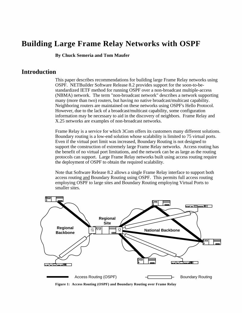
Note that Software Release 8.2 allows a single Frame Relay interface to support bothaccess routing and Boundary Routing using OSPF. This permits full access routingemploying OSPF to large sites and Boundary Routing employing Virtual Ports tosmaller sites.
National BackboneRegional
Backbone
Boundary RoutingAccess Routing (OSPF)
RegionalSite
!1 !2
Figure 1: Access Routing (OSPF) and Boundary Routing over Frame Relay
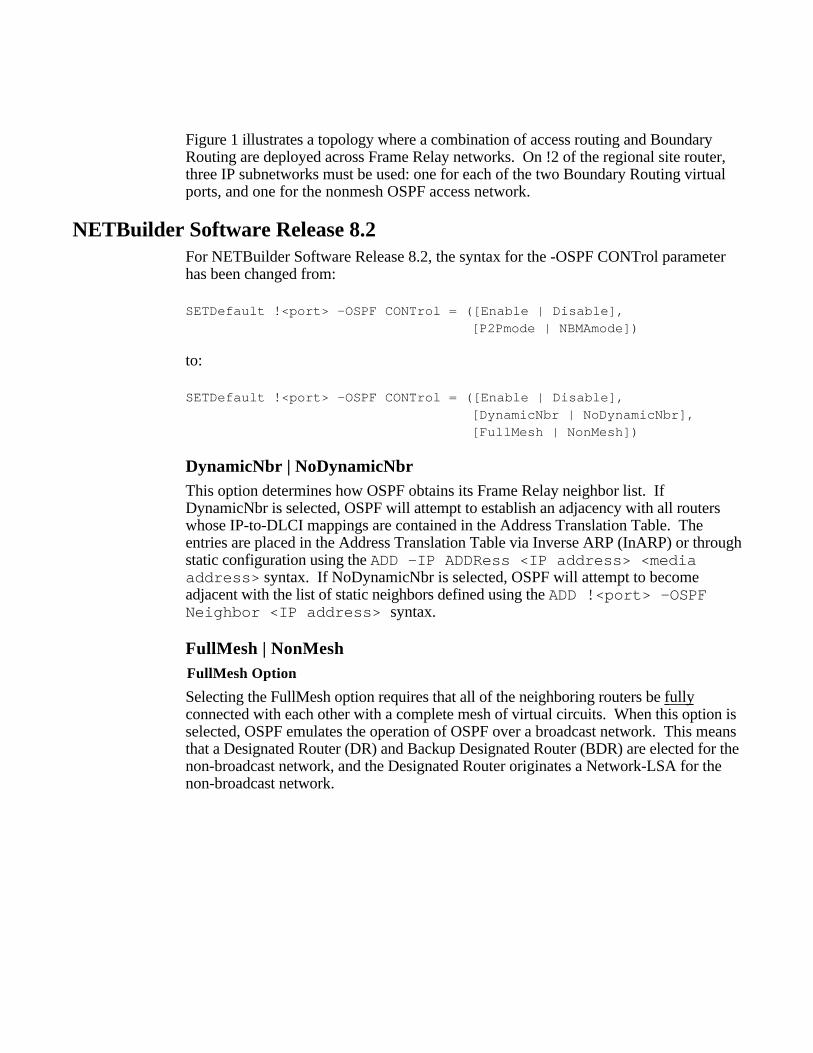
Figure 1 illustrates a topology where a combination of access routing and BoundaryRouting are deployed across Frame Relay networks. On !2 of the regional site router,three IP subnetworks must be used: one for each of the two Boundary Routing virtualports, and one for the nonmesh OSPF access network.
NETBuilder Software Release 8.2For NETBuilder Software Release 8.2, the syntax for the -OSPF CONTrol parameterhas been changed from:
SETDefault !<port> -OSPF CONTrol = ([Enable | Disable], [P2Pmode | NBMAmode])
to:
SETDefault !<port> -OSPF CONTrol = ([Enable | Disable], [DynamicNbr | NoDynamicNbr], [FullMesh | NonMesh])
DynamicNbr | NoDynamicNbrThis option determines how OSPF obtains its Frame Relay neighbor list. IfDynamicNbr is selected, OSPF will attempt to establish an adjacency with all routerswhose IP-to-DLCI mappings are contained in the Address Translation Table. Theentries are placed in the Address Translation Table via Inverse ARP (InARP) or throughstatic configuration using the ADD -IP ADDRess <IP address> <mediaaddress> syntax. If NoDynamicNbr is selected, OSPF will attempt to becomeadjacent with the list of static neighbors defined using the ADD !<port> -OSPFNeighbor <IP address> syntax.
FullMesh | NonMeshFullMesh Option
Selecting the FullMesh option requires that all of the neighboring routers be fully connected with each other with a complete mesh of virtual circuits. When this option isselected, OSPF emulates the operation of OSPF over a broadcast network. This meansthat a Designated Router (DR) and Backup Designated Router (BDR) are elected for thenon-broadcast network, and the Designated Router originates a Network-LSA for thenon-broadcast network.
FullMesh NonMesh
Figure 2: FullMesh vs. NonMesh Topologies
It should be emphasized that FullMesh topologies are impracticable for large FrameRelay networks because they do not scale:
* A large, fully-meshed Frame Relay network requires a separate virtual circuit foreach link between neighbors. A FullMesh topology requires [n(n-1)]/2 virtualcircuits, where n is the number of routers connected to the Frame Relay network.This means that a FullMesh topology consisting of 5 routers requires 10 virtualcircuits while a FullMesh topology consisting of 7 routers requires 21 virtual circuits- a 110% increase in the number of virtual circuits that must be purchased from theservice provider!
* The lack of a network broadcast/multicast capability requires that a router unicaststandard protocol broadcast/multicast frames to each virtual circuit for that FrameRelay interface. This occurs whenever OSPF Hellos, LSD Updates, etc. must betransmitted. As the number of virtual circuits increases, router broadcast/multicastreplication can consume a considerable amount of the Frame Relay network'sbandwidth.
For these reasons, FullMesh topologies should only be deployed in small Frame Relaynetworks. Economics dictate that large Frame Relay networks be built using NonMeshtopologies.
NonMesh Option
Selecting the NonMesh option causes OSPF to run in the soon-to-be-standardizedPoint-to-MultiPoint mode. If this option is selected, OSPF treats each router-to-routerconnection as if it were a separate point-to-point link. Point-to-MultiPoint networkshave been designed to work simply and naturally when faced with partial meshconnectivity. This means that:
* A DR and BDR are not elected for the Frame Relay network.
* A Network-LSA is not originated for the Frame Relay network.
* Point-to-point adjacencies are established between each set of directlycommunicating neighboring routers. A point-to-point adjacency in steady state willbe either Full or Down, but never 2-Way.
* Separate Hello packets are sent to each attached neighbor every HelloTime interval.To improve scalability in Software Release 9.0, the Hello transmissions will be sentout evenly over time so that there will be a steady stream of Hellos rather than alarge burst every 10 seconds. Note that Software Release 8.3 allows you use theSETDefault !<port> -OSPF DemandInterface = Enable syntax toeliminate the transmission of Hellos and periodic LSAs, but real topology changeswill still be flooded over the network.
* When originating a Router-LSA, the Point-to-MultiPoint interface is reported as acollection of "point-to-point links" to each of the interface's adjacent neighbors.
NonMesh is ideal for building large Frame Relay networks since it does not require thatall routers to be able to communicate directly.
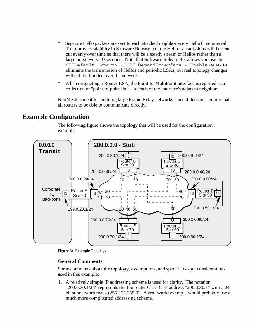
Example ConfigurationThe following figure shows the topology that will be used for the configurationexample:
Router A Router DSite 50Site 20
20 60 70 50
4070
504020
3070
CorporateHQ
Backbone
30
Router B Router C
Router F Router E
200.0.0.30/24 200.0.0.40/24
200.0.0.70/24 200.0.0.60/24
200.0.0.50/24200.0.0.20/24
200.0.40.1/24
200.0.70.1/24 200.0.60.1/24
200.0.50.1/24
200.0.30.1/24
199.0.20.1/24
Site 60Site 70
Site 30 Site 40
0.0.0.0Transit
200.0.0.0 - Stub
!3 !3
!3 !3
!3!3
!1 !1
!1 !1
!1!1
Figure 3: Example Topology
General CommentsSome comments about the topology, assumptions, and specific design considerationsused in this example:
1. A relatively simple IP addressing scheme is used for clarity. The notation"200.0.30.1/24" represents the four octet Class C IP address "200.0.30.1" with a 24bit subnetwork mask (255.255.255.0). A real-world example would probably use amuch more complicated addressing scheme.
2. The Frame Relay service provider's switches implement the ANSI LMI whichsupports the global addressing extension. Note that most switches auto-sense theLMI type used by the CPE.
3. DLCIs have been assigned using "site-based" addressing where each site has aunique DLCI. The DLCI that has been assigned to each site by the service provideris indicated in each of the router icons. The alternative would have been to use"PVC-based" addressing where each PVC has the same DLCI on each end. In thegraphic, note that the DLCI label within the Frame Relay cloud at the end of eachvirtual circuit indicates the "site" address at the other end of the virtual circuit.
4. The example assumes that dynamic address resolution is employed across theFrame Relay network via Inverse ARP (InARP). If InARP is not supported, staticmappings must be placed in the Address Translation Table using the ADD -IPADDRess <IP address> @<DLCI#> syntax. Each of the routerconfigurations examples show the alternate steps required for static addressresolution if it were to become part of the design specification.
5. The example assumes that OSPF will dynamically learn about neighboring routersfrom the mappings InARP places in the Address Translation Table. If security orother requirements demand static neighbor configuration, an OSPF neighbor listmust be created using the ADD !<port> -OSPF Neighbor <IP address>syntax. For total control, SETD !<port> -ARP CONTrol = NoInARP andperform static address resolution using the ADD -IP ADDRess <IP address>@<DLCI#> syntax. Each of the router configurations examples show the alternatesteps required for static neighbor configuration if it were to become part of thedesign specification.
6. The networks located at the corporate headquarters are in Area 0.0.0.0-Transit whilethe Frame Relay network and each of the regional site networks are assigned to Area200.0.0.0-Stub. One benefit of this design is that it eliminates the flooding ofExternal-LSAs into the Frame Relay network since OSPF does not flood External-LSAs into Stub areas. Another benefit is that Router A functions as an Area BorderRouter (ABR) which keeps topology changes in Area 0.0.0.0 from causing aDijkstra calculation in Area 200.0.0.0 and vice versa. Note that area 200.0.0.0 hadto contain each of the remote site LANs or else Virtual Links would have had to bedefined.
An alternate OSPF Area configuration would be to have the router interfaces on theFrame Relay network and the corporate headquarters networks all contained in Area0.0.0.0. This permits the location of stub or transit areas at each remote site, butcauses External-LSAs to be flooded throughout the Frame Relay network and willresult in a larger number of routers performing a Dijkstra calculation if any topologychange takes place in Area 0.0.0.0.
Router A ConfigurationBasic configuration parameters:
SETDefault !3 -POrt OWner = FrameRelaySETDefault !3 -ARP CONTrol = InARP (Default setting)SETDefault !3 -FrameRelay CONTrol = ANsiLMISETDefault -IP CONTrol = ROuteSETDefault !1 -IP NETaddr 199.0.20.1SETDefault !3 -IP NETaddr 200.0.0.20SETDefault !1 -OSPF AreaId = 0.0.0.0 Transit (Default setting)SETDefault !3 -OSPF AreaId = 200.0.0.0 StubSETDefault !1 -OSPF CONTrol = EnableSETDefault !3 -OSPF CONTrol = (Enable, DynamicNbr, NonMesh)
If the design requires that InARP be disabled and static address resolution be performedfor the Frame Relay network. Note that Neighbors can still be dynamically learned forthis network design:
SETDefault !3 -ARP CONTrol = NoInARPADD -IP ADDRess 200.0.0.30 @30ADD -IP ADDRess 200.0.0.70 @70
If security or other considerations required static neighbor configuration for the FrameRelay network:
SETDefault !3 -OSPF CONTrol = (Enable, NoDynamicNbr , NonMesh)
ADD !3 -OSPF Neighbor 200.0.0.30ADD !3 -OSPF Neighbor 200.0.0.70SETDefault !3 -ARP CONTrol = NoInARPADD -IP ADDRess 200.0.0.30 @30ADD -IP ADDRess 200.0.0.70 @70
Router B ConfigurationBasic configuration parameters:
SETDefault !3 -POrt OWner = FrameRelaySETDefault !3 -ARP CONTrol = InARP (Default setting)SETDefault !3 -FrameRelay CONTrol = ANsiLMISETDefault -IP CONTrol = ROuteSETDefault !1 -IP NETaddr 200.0.30.1SETDefault !3 -IP NETaddr 200.0.0.30SETDefault !1 -OSPF AreaId = 200.0.0.0 StubSETDefault !3 -OSPF AreaId = 200.0.0.0 StubSETDefault !1 -OSPF CONTrol = EnableSETDefault !3 -OSPF CONTrol = (Enable, DynamicNbr, NonMesh)
If the design required that InARP be disabled and static address resolution be performedfor the Frame Relay network:
SETDefault !3 -ARP CONTrol = NoInARPADD -IP ADDRess 200.0.0.20 @20ADD -IP ADDRess 200.0.0.60 @60
If security or other considerations required static neighbor configuration for the FrameRelay network:
SETDefault !3 -OSPF CONTrol = (Enable, NoDynamicNbr , NonMesh)
ADD !3 -OSPF Neighbor 200.0.0.20ADD !3 -OSPF Neighbor 200.0.0.60SETDefault !3 -ARP CONTrol = NoInARPADD -IP ADDRess 200.0.0.20 @20ADD -IP ADDRess 200.0.0.60 @60
Router C ConfigurationBasic configuration parameters:
SETDefault !3 -POrt OWner = FrameRelaySETDefault !3 -ARP CONTrol = InARP (Default setting)SETDefault !3 -FrameRelay CONTrol = ANsiLMISETDefault -IP CONTrol = ROuteSETDefault !1 -IP NETaddr 200.0.40.1SETDefault !3 -IP NETaddr 200.0.0.40SETDefault !1 -OSPF AreaId = 200.0.0.0 StubSETDefault !3 -OSPF AreaId = 200.0.0.0 StubSETDefault !1 -OSPF CONTrol = EnableSETDefault !3 -OSPF CONTrol = (Enable, DynamicNbr, NonMesh)
If the design required that InARP be disabled and static address resolution be performedfor the Frame Relay network:
SETDefault !3 -ARP CONTrol = NoInARPADD -IP ADDRess 200.0.0.50 @50ADD -IP ADDRess 200.0.0.70 @70
If security or other considerations required static neighbor configuration for the FrameRelay network:
SETDefault !3 -OSPF CONTrol = (Enable, NoDynamicNbr , NonMesh)
ADD !3 -OSPF Neighbor 200.0.0.50ADD !3 -OSPF Neighbor 200.0.0.70SETDefault !3 -ARP CONTrol = NoInARPADD -IP ADDRess 200.0.0.50 @50ADD -IP ADDRess 200.0.0.70 @70
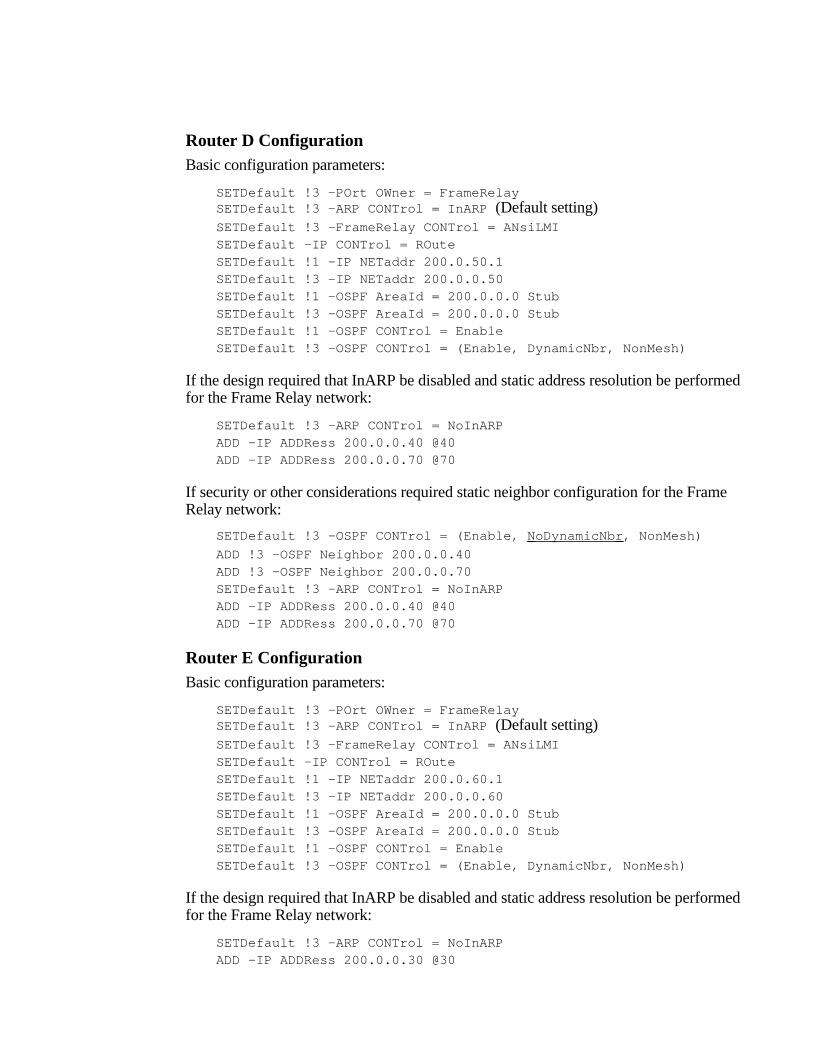
Router D ConfigurationBasic configuration parameters:
SETDefault !3 -POrt OWner = FrameRelaySETDefault !3 -ARP CONTrol = InARP (Default setting)SETDefault !3 -FrameRelay CONTrol = ANsiLMISETDefault -IP CONTrol = ROuteSETDefault !1 -IP NETaddr 200.0.50.1SETDefault !3 -IP NETaddr 200.0.0.50SETDefault !1 -OSPF AreaId = 200.0.0.0 StubSETDefault !3 -OSPF AreaId = 200.0.0.0 StubSETDefault !1 -OSPF CONTrol = EnableSETDefault !3 -OSPF CONTrol = (Enable, DynamicNbr, NonMesh)
If the design required that InARP be disabled and static address resolution be performedfor the Frame Relay network:
SETDefault !3 -ARP CONTrol = NoInARPADD -IP ADDRess 200.0.0.40 @40ADD -IP ADDRess 200.0.0.70 @70
If security or other considerations required static neighbor configuration for the FrameRelay network:
SETDefault !3 -OSPF CONTrol = (Enable, NoDynamicNbr , NonMesh)
ADD !3 -OSPF Neighbor 200.0.0.40ADD !3 -OSPF Neighbor 200.0.0.70SETDefault !3 -ARP CONTrol = NoInARPADD -IP ADDRess 200.0.0.40 @40ADD -IP ADDRess 200.0.0.70 @70
Router E ConfigurationBasic configuration parameters:
SETDefault !3 -POrt OWner = FrameRelaySETDefault !3 -ARP CONTrol = InARP (Default setting)SETDefault !3 -FrameRelay CONTrol = ANsiLMISETDefault -IP CONTrol = ROuteSETDefault !1 -IP NETaddr 200.0.60.1SETDefault !3 -IP NETaddr 200.0.0.60SETDefault !1 -OSPF AreaId = 200.0.0.0 StubSETDefault !3 -OSPF AreaId = 200.0.0.0 StubSETDefault !1 -OSPF CONTrol = EnableSETDefault !3 -OSPF CONTrol = (Enable, DynamicNbr, NonMesh)
If the design required that InARP be disabled and static address resolution be performedfor the Frame Relay network:
SETDefault !3 -ARP CONTrol = NoInARPADD -IP ADDRess 200.0.0.30 @30
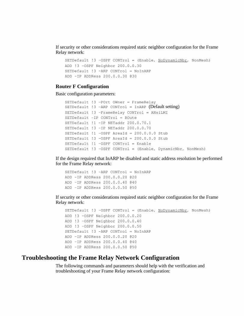
If security or other considerations required static neighbor configuration for the FrameRelay network:
SETDefault !3 -OSPF CONTrol = (Enable, NoDynamicNbr , NonMesh)
ADD !3 -OSPF Neighbor 200.0.0.30SETDefault !3 -ARP CONTrol = NoInARPADD -IP ADDRess 200.0.0.30 @30
Router F ConfigurationBasic configuration parameters:
SETDefault !3 -POrt OWner = FrameRelaySETDefault !3 -ARP CONTrol = InARP (Default setting)SETDefault !3 -FrameRelay CONTrol = ANsiLMISETDefault -IP CONTrol = ROuteSETDefault !1 -IP NETaddr 200.0.70.1SETDefault !3 -IP NETaddr 200.0.0.70SETDefault !1 -OSPF AreaId = 200.0.0.0 StubSETDefault !3 -OSPF AreaId = 200.0.0.0 StubSETDefault !1 -OSPF CONTrol = EnableSETDefault !3 -OSPF CONTrol = (Enable, DynamicNbr, NonMesh)
If the design required that InARP be disabled and static address resolution be performedfor the Frame Relay network:
SETDefault !3 -ARP CONTrol = NoInARPADD -IP ADDRess 200.0.0.20 @20ADD -IP ADDRess 200.0.0.40 @40ADD -IP ADDRess 200.0.0.50 @50
If security or other considerations required static neighbor configuration for the FrameRelay network:
SETDefault !3 -OSPF CONTrol = (Enable, NoDynamicNbr , NonMesh)
ADD !3 -OSPF Neighbor 200.0.0.20ADD !3 -OSPF Neighbor 200.0.0.40ADD !3 -OSPF Neighbor 200.0.0.50SETDefault !3 -ARP CONTrol = NoInARPADD -IP ADDRess 200.0.0.20 @20ADD -IP ADDRess 200.0.0.40 @40ADD -IP ADDRess 200.0.0.50 @50
Troubleshooting the Frame Relay Network ConfigurationThe following commands and parameters should help with the verification andtroubleshooting of your Frame Relay network configuration:
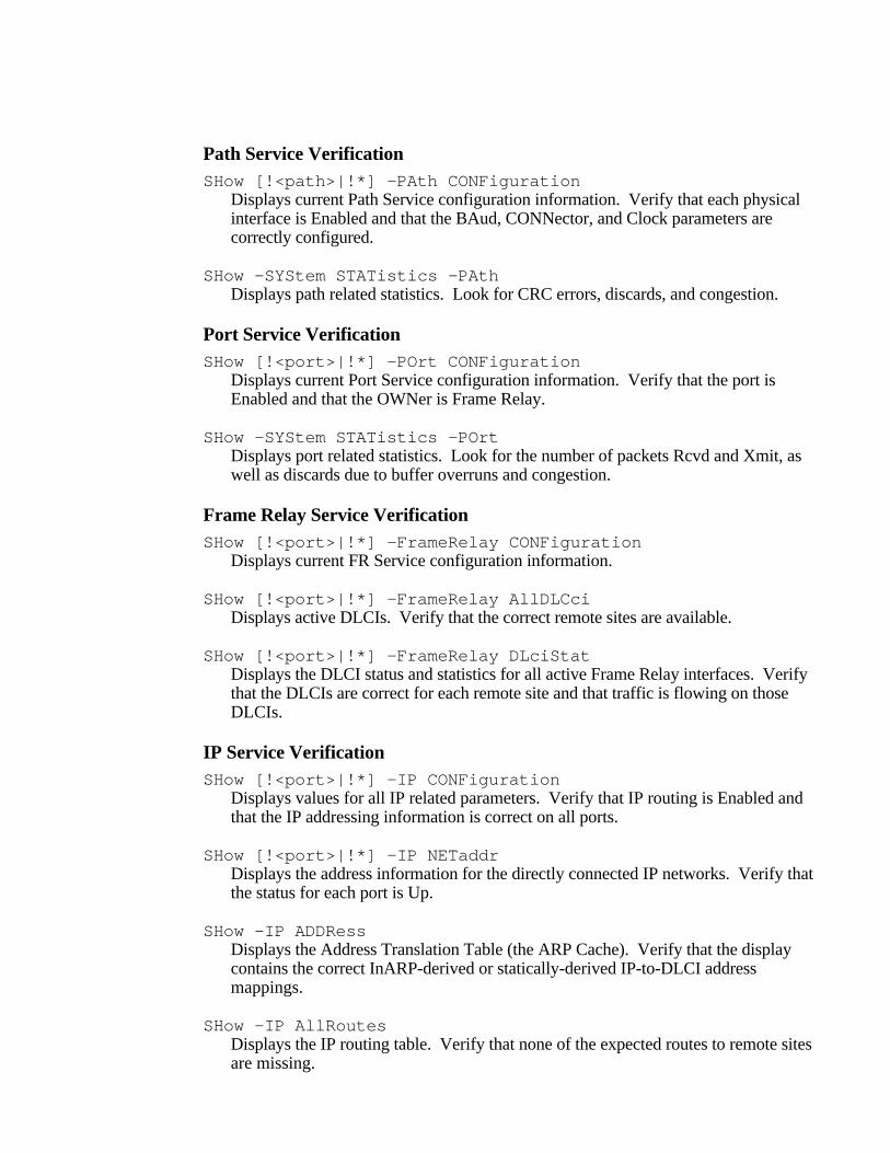
Path Service VerificationSHow [!<path>|!*] -PAth CONFiguration
Displays current Path Service configuration information. Verify that each physicalinterface is Enabled and that the BAud, CONNector, and Clock parameters arecorrectly configured.
SHow -SYStem STATistics -PAthDisplays path related statistics. Look for CRC errors, discards, and congestion.
Port Service VerificationSHow [!<port>|!*] -POrt CONFiguration
Displays current Port Service configuration information. Verify that the port isEnabled and that the OWNer is Frame Relay.
SHow -SYStem STATistics -POrtDisplays port related statistics. Look for the number of packets Rcvd and Xmit, aswell as discards due to buffer overruns and congestion.
Frame Relay Service VerificationSHow [!<port>|!*] -FrameRelay CONFiguration
Displays current FR Service configuration information.
SHow [!<port>|!*] -FrameRelay AllDLCciDisplays active DLCIs. Verify that the correct remote sites are available.
SHow [!<port>|!*] -FrameRelay DLciStatDisplays the DLCI status and statistics for all active Frame Relay interfaces. Verifythat the DLCIs are correct for each remote site and that traffic is flowing on thoseDLCIs.
IP Service VerificationSHow [!<port>|!*] -IP CONFiguration
Displays values for all IP related parameters. Verify that IP routing is Enabled andthat the IP addressing information is correct on all ports.
SHow [!<port>|!*] -IP NETaddrDisplays the address information for the directly connected IP networks. Verify thatthe status for each port is Up.
SHow -IP ADDRessDisplays the Address Translation Table (the ARP Cache). Verify that the displaycontains the correct InARP-derived or statically-derived IP-to-DLCI addressmappings.
SHow -IP AllRoutesDisplays the IP routing table. Verify that none of the expected routes to remote sitesare missing.
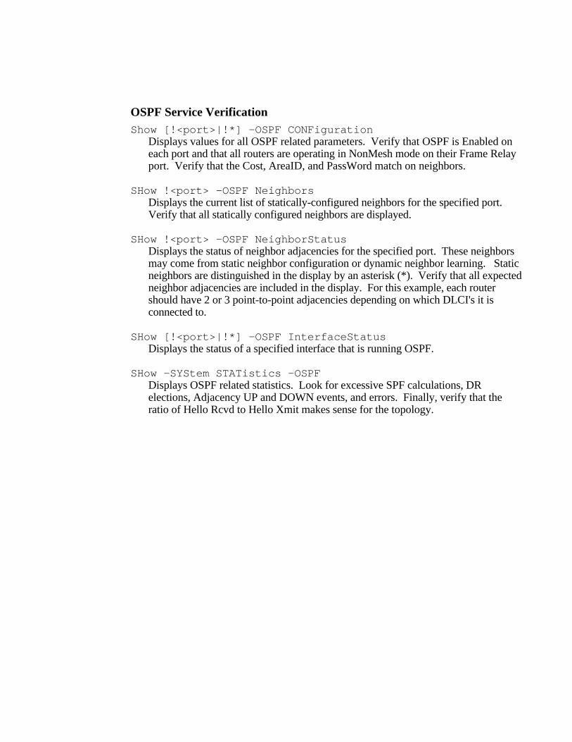
OSPF Service VerificationShow [!<port>|!*] -OSPF CONFiguration
Displays values for all OSPF related parameters. Verify that OSPF is Enabled oneach port and that all routers are operating in NonMesh mode on their Frame Relayport. Verify that the Cost, AreaID, and PassWord match on neighbors.
SHow !<port> -OSPF NeighborsDisplays the current list of statically-configured neighbors for the specified port.Verify that all statically configured neighbors are displayed.
SHow !<port> -OSPF NeighborStatusDisplays the status of neighbor adjacencies for the specified port. These neighborsmay come from static neighbor configuration or dynamic neighbor learning. Staticneighbors are distinguished in the display by an asterisk (*). Verify that all expectedneighbor adjacencies are included in the display. For this example, each routershould have 2 or 3 point-to-point adjacencies depending on which DLCI's it isconnected to.
SHow [!<port>|!*] -OSPF InterfaceStatusDisplays the status of a specified interface that is running OSPF.
SHow -SYStem STATistics -OSPFDisplays OSPF related statistics. Look for excessive SPF calculations, DRelections, Adjacency UP and DOWN events, and errors. Finally, verify that theratio of Hello Rcvd to Hello Xmit makes sense for the topology.