Embed Size (px)
Citation preview
1
IMPORTANT: READ THESE INSTRUCTIONS CAREFULLY BEFORE STARTING INSTALLATION OR USE.
DANGER:IF YOU SMELL GAS:1. Shut off the gas to the appliance.2. Extinguish any open flame. 3. Open lid.4. If odor continues, keep away from the
appliance and immediately call your gas supplier or the fire department.
WARNING:1. Do not store or use gasoline or other
flammable vapors and liquids in the vicinity of this or any other appliance.
2. An LP cylinder not connected for use shall not be stored in the vicinity of this or any other appliance.
CODE AND SUPPLY REQUIREMENTS: This grill must be installed in accordance with local codes and ordinances, or, in the absence of local codes, with the latest National Fuel Gas Code (ANSI Z223.1/NFPA 54), or Natural Gas and Propane Storage and Handling Installation Code (CSA-B149.1).This appliance and its dedicated manual shutoff valve must be disconnected from the gas-supply piping system when testing the system at pressures in excess of ½ psig (3.5 kPa).This appliance must be isolated from the gas-supply piping system by closing its dedicated manual shutoff valve during any pressure testing of the gas-supply system at pressures up to and including ½ psig (3.5 kPa).
All electrical outlets in the vicinity of the grill must be properly grounded in accordance with local codes, or, in the absence of local codes, with the National Electrical Code, ANSI/NFPA 70, or the Canadian Electrical Code, CSA C22.1, whichever is applicable.
Keep all electrical-supply cords and fuel-supply hoses away from any heated surface.
INSTALLER: Leave these instructions with consumer.CONSUMER: Retain for future reference.
WARNING:Improper installation, adjustment, alteration, service, or maintenance can cause injury or property damage. For proper installation, refer to the installation instructions. For assistance or additional information, consult a qualified professional service technician,
service agency, or the gas supplier.
Proper operation of your grill requires prompt and periodic maintenance. See the SERVICING AND CLEANING section for details.
Certified to: ANSI Z21.58 CSA 1.6
INSTALLATION AND OWNER’S MANUAL
US®
C
ONLY TO BE USED OUTDOORS
American Outdoor Grill • PO Box 4053 • La Puente, CA 91747
WARNINGS AND SAFETY CODES
BUILT-IN OUTDOOR GAS GRILLS
GETTING STARTED
REV 4 - 2007101150 L-C2-437
24, 30, & 36 "L" Series
2
IMPORTANT: LISEZ CES INSTRUCTIONS SOIGNEUSEMENT AVANT DE COMMENCER L’INSTALLATION OU L’UTILISATION
GRIL EXTÉRIEUR DE GAZ DU BUILT-IN
DANGER:SI VOUS SENTEZ LE GAZ :1. Coupez le gaz à l’appareil.2. Éteignez-vous n’importe quelle flamme nue. 3. Ouvrez le couvercle.4. Si l’odeur continue, gardez loin de
l’appareil et appelez immédiatement votre département de fournisseur ou de feu de gaz.
AVERTISSEMENT:1. Ne stockez pas ou n’employez pas
l’essence ou d’autres vapeurs et liquides inflammables à proximité de ceci ou d’aucun autre appareil.
2. Un cylindre de propane non relié pour l’usage ne sera pas stocké à proximité de ceci ou d’aucun autre appareil.
CONDITIONS DE CODE ET D’APPROVISIONNEMENT: Ce gril doit être installé selon des codes et des ordonnances locaux, ou, en l’absence des codes locaux, avec l’un ou l’autre le plus défunt Code national de gaz de carburant (norme ANSI Z223.1/NFPA 54), et Stockage de gaz naturel et de propane et manipulation du code d’installation (CSA-B149.1).Cet appareil et ses différents robinets d’isolement doivent être démontés du gaz-fournissent le système sifflant en examinant le système aux pressions au-dessus du ½ psig (kPa 3.5).Cet appareil doit être isolé dans gaz-fournissent le système sifflant par fermeture que ses différents robinets d’isolement manuels pendant tous les essais sous pression du gaz-fournissent le système aux pressions jusques et y compris le ½ psig (kPa 3.5).
Toutes les sorties électriques à proximité du gril doivent être correctement fondues selon des codes locaux, ou en l’absence de local code, avec le code électrique national, ANSI/NFPA 70, ou le code électrique canadien, CSA C22.1, celui qui est applicable.
Maintenez tout électrique-fournissent des cordes et carburant-fournissent des tuyaux partis de n’importe quelle surface de chauffage.
INSTALLATEUR : Laissez ces instructions avec le consommateur. CONSOMMATEUR : Maintenez pour la future référence.
AVERTISSEMENT:L’installation inexacte, l’ajustement, le changement, le service, ou l’entretien peuvent causer des dommages ou des dégats matériels. Référez-vous à ce manuel. Pour de l'aide ou des renseignements supplémentaires, consultez un technicien professionnel qualifié de service, une agence de service ou le fournisseur de gaz.
• Ce gril est pour ultilisation à l’extérieur seulement. Si l’appareil est entreposé à l’intérieur, enlever les bouteilles et les laisser à l’extérieur.
• Ne pas ranger le gril immédiatement aprés l’avoir utilisé. le laisser refroidir avant de le déplacer ou de la ranger. Le non respect de cette mesure de sécurité pourrait entraîner un incendie causant des dommages à la propriété, des blessures ou la mort.
• Ne pas utiliser cet appareil sous une surface combustible.• Ne pas utiliser cet appareil sous un auvent. Le non
respect de cette mesure de sécurité pourrait entraîner un incendie ou des blessures.
• Dégagement minimal entre les parois latérales et l’arriére de l’appareil et la construction combustible (45.7 cm à partir des parois latérales et 45.7cm à partir de l’arriére).
• Le régulareur de pression de gaz prévu avec cet appareil de cuisson à gaz pour l’extérieur doit être utilisé. Ce régulateur est réglé pour une pression de sortie de 5 pouces de colonne de l’eau pour le gaz naturel, et 10 pouces pour le propane.
• LE RÉGULATEUR INCLUS D’APPAREILS EST ÉVALUÉ POUR LE MAXIMUM DE 1/2 (LIVRES PAR POUCE CARRÉ). SI VOTRE OFFRE DE GAZ EST 1/2 PLUS GRAND QUE (LIVRES PAR POUCE CARRÉ), UN RÉGULATEUR ADDITIONNEL DOIT ÊTRE INSTALLÉ AVANT LE GRIL. VOIR LA SECTION DE CONDITIONS D’OFFRE DE GAZ POUR LA PRESSION APPROPRIÉE D’OFFRE DE GAZ.
• Ne couvrez jamais la surface entière de cuisine ou de gril de gauffreuses ou de casseroles. La surchauffe se produira et les brûleurs ne seront pas très performants quand la chaleur de combustion est emprisonnée au-dessous de la surface à cuire.
• Ne pulvérisez jamais l’eau sur une unité chaude de gaz, comme ceci peut endommager des composants de porcelaine ou de fer de fonte.
• Une fuite de GPL peut causer une incendie ou une explosion si enflammée entraînant des blessures corporelles graves ou la mort.
• Communiquez avec le fournisseur de GPL pour les réparations ou pour disposer de qules bouteille ou du GPL non utilisé.
Certifié à la norme: ANSI Z21.58 / CSA 1.6
SÛRETÉ ET CODES D’AVERTISSEMENT
INSTALLATION INSTRUCTIONS ET MANUEL DU PROPRIÉTAIRE
À UTILISER UNIQUEMENT À L'EXTÉRIEUR
REV 4 - 2007101150 L-C2-437
3
TABLE OF CONTENTS
REV 4 - 2007101150 L-C2-437
GETTING STARTEDWARNINGS AND SAFETY CODES ������������������������������������1INSTALLATION, OPERATION, AND SAFETY INFORMATION ���������������������������������������������������������������������4
ELECTRICAL CONNECTIONS �����������������������������������������4GAS SAFETY INFORMATION ��������������������������������������������5
WARNING �����������������������������������������������������������������������5WHEN USING PROPANE GAS ������������������������������������������5WHEN USING NATURAL GAS ������������������������������������������5INSTALLATION SAFETY GUIDELINES �����������������������������5
OPERATING THE UNIT SAFELY AND CORRECTLY ������5SAFE USE & MAINTENANCE OF PROPANE GAS CYLINDERS ��������������������������������������������������������������������������7GRILL ENCLOSURE / VENTILATION REQUIREMENTS �����������������������������������������������������������������8
ENCLOSURE �������������������������������������������������������������������9WHEN A PROPANE (L.P.) CYLINDER IS USED IN THE ENCLOSURE �����������������������������������������������������������9
INSTALLATION REQUIREMENTS ����������������������������������10OVERHEAD CONSTRUCTION AND EXHAUST HOOD REQUIREMENTS �����������������������������������������������������������10REAR WALL CLEARANCES ��������������������������������������������11BACKSPLASH CLEARANCE (if applicable) ���������������������11SIDE WALL / CORNER WALL CLEARANCES (if applicable) ������������������������������������������11CONTROL PANEL CLEARANCES �����������������������������������12COMBUSTION AIR AND COOLING AIRFLOW ���������������12GAS-SUPPLY PLUMBING REQUIREMENTS ������������������12
ELECTRICAL SAFETY ������������������������������������������������������13MODEL SPECIFICATIONS ������������������������������������������������14
COUNTERTOP OVERHANG ������������������������������������������15ENCLOSURE VENTILATION ������������������������������������������15SUBSTRATE ������������������������������������������������������������������16BUILT-IN GRILL WIRING DIAGRAM ������������������������������16
AOG GRILL REPLACEMENT PARTS LIST ���������������������17
INSTALLATIONINSTALLATION ������������������������������������������������������������������ 20
COUNTER PREPARATION ��������������������������������������������� 20CONNECT THE GAS SUPPLY ����������������������������������������� 20INSTALL THE VAPORIZER PANELS�������������������������������� 21INSTALL THE COOKING GRIDS ������������������������������������ 22INSTALL THE DRIP TRAY ���������������������������������������������� 22
ELECTRICAL INSTALLATION ����������������������������������������� 23
USE, CARE, & SERVICEIDENTIFICATION OF GRILL CONTROLS ���������������������� 24USING THE GRILL ������������������������������������������������������������� 25LIGHTING (IGNITION) INSTRUCTIONS ������������������������ 27
ELECTRONIC LIGHTING ���������������������������������������������� 27ELECTRONIC LIGHTING ���������������������������������������������� 27MANUAL LIGHTING������������������������������������������������������ 27SHUTTING OFF THE UNIT ������������������������������������������� 27
OPTIONAL INFRARED BURNER OPERATION ������������� 28ROTISSERIE INSTRUCTIONS (IF EQUIPPED) �������������� 29SERVICING AND CLEANING ������������������������������������������ 30
CLEANING YOUR GRILL ����������������������������������������������� 30REPLACING HALOGEN BULBS ������������������������������������� 32CONTROL PANEL REMOVAL ����������������������������������������� 33FUSE REPLACEMENT ��������������������������������������������������� 34BURNER REMOVAL������������������������������������������������������� 34CONVERT GAS TYPE / CHECK BURNER ORIFICES ������ 35AIR SHUTTER ADJUSTMENT ���������������������������������������� 38
TROUBLESHOOTING ������������������������������������������������������� 39WARRANTY ������������������������������������������������������������������������ 40
COMMONWEALTH OF MASSACHUSETTS REQUIREMENTS ����������������������������������������������������������� 40
4
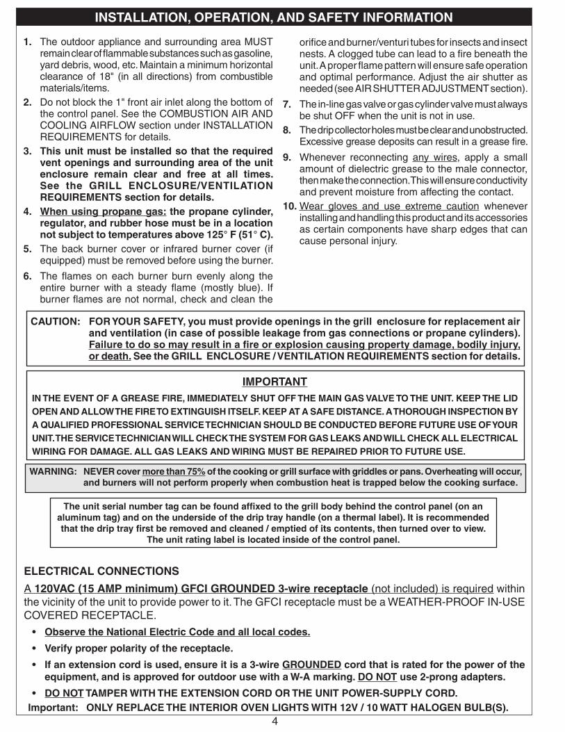
1. The outdoor appliance and surrounding area MUST remain clear of flammable substances such as gasoline, yard debris, wood, etc. Maintain a minimum horizontal clearance of 18" (in all directions) from combustible materials/items.
2. Do not block the 1" front air inlet along the bottom of the control panel. See the COMBUSTION AIR AND COOLING AIRFLOW section under INSTALLATION REQUIREMENTS for details.
3. This unit must be installed so that the required vent openings and surrounding area of the unit enclosure remain clear and free at all times. See the GRILL ENCLOSURE/VENTILATION REQUIREMENTS section for details.
4. When using propane gas: the propane cylinder, regulator, and rubber hose must be in a location not subject to temperatures above 125° F (51° C).
5. The back burner cover or infrared burner cover (if equipped) must be removed before using the burner.
6. The flames on each burner burn evenly along the entire burner with a steady flame (mostly blue). If burner flames are not normal, check and clean the
orifice and burner/venturi tubes for insects and insect nests. A clogged tube can lead to a fire beneath the unit. A proper flame pattern will ensure safe operation and optimal performance. Adjust the air shutter as needed (see AIR SHUTTER ADJUSTMENT section).
7. The in-line gas valve or gas cylinder valve must always be shut OFF when the unit is not in use.
8. The drip collector holes must be clear and unobstructed. Excessive grease deposits can result in a grease fire.
9. Whenever reconnecting any wires, apply a small amount of dielectric grease to the male connector, then make the connection. This will ensure conductivity and prevent moisture from affecting the contact.
10. Wear gloves and use extreme caution whenever installing and handling this product and its accessories as certain components have sharp edges that can cause personal injury.
WARNING: NEVER cover more than 75% of the cooking or grill surface with griddles or pans. Overheating will occur, and burners will not perform properly when combustion heat is trapped below the cooking surface.
IMPORTANTIN THE EVENT OF A GREASE FIRE, IMMEDIATELY SHUT OFF THE MAIN GAS VALVE TO THE UNIT. KEEP THE LID OPEN AND ALLOW THE FIRE TO EXTINGUISH ITSELF. KEEP AT A SAFE DISTANCE. A THOROUGH INSPECTION BY A QUALIFIED PROFESSIONAL SERVICE TECHNICIAN SHOULD BE CONDUCTED BEFORE FUTURE USE OF YOUR UNIT. THE SERVICE TECHNICIAN WILL CHECK THE SYSTEM FOR GAS LEAKS AND WILL CHECK ALL ELECTRICAL WIRING FOR DAMAGE. ALL GAS LEAKS AND WIRING MUST BE REPAIRED PRIOR TO FUTURE USE.
ELECTRICAL CONNECTIONS
A 120VAC (15 AMP minimum) GFCI GROUNDED 3-wire receptacle (not included) is required within the vicinity of the unit to provide power to it. The GFCI receptacle must be a WEATHER-PROOF IN-USE COVERED RECEPTACLE.
• Observe the National Electric Code and all local codes.
• Verify proper polarity of the receptacle.
• If an extension cord is used, ensure it is a 3-wire GROUNDED cord that is rated for the power of the equipment, and is approved for outdoor use with a W-A marking. DO NOT use 2-prong adapters.
• DO NOT TAMPER WITH THE EXTENSION CORD OR THE UNIT POWER-SUPPLY CORD.Important: ONLY REPLACE THE INTERIOR OVEN LIGHTS WITH 12V / 10 WATT HALOGEN BULB(S).
CAUTION: FOR YOUR SAFETY, you must provide openings in the grill enclosure for replacement air and ventilation (in case of possible leakage from gas connections or propane cylinders). Failure to do so may result in a fire or explosion causing property damage, bodily injury, or death. See the GRILL ENCLOSURE / VENTILATION REQUIREMENTS section for details.
The unit serial number tag can be found affixed to the grill body behind the control panel (on an aluminum tag) and on the underside of the drip tray handle (on a thermal label). It is recommended that the drip tray first be removed and cleaned / emptied of its contents, then turned over to view.
The unit rating label is located inside of the control panel.
INSTALLATION, OPERATION, AND SAFETY INFORMATION
5
WARNING This gas appliance, its enclosure, and the propane cylinder enclosure, if any, MUST be plumbed and vented in accordance with local building and safety codes and should be approved by local code enforcement
officials. This appliance MUST be installed and operated according to the information below.
FAILURE TO PROPERLY VENT THE GRILL ENCLOSURE MAY RESULT IN A FIRE OR EXPLOSION CAUSING PROPERTY DAMAGE, BODILY INJURY, OR DEATH.
A leaking gas connection or valve unintentionally left open will create a hazard.
WHEN USING PROPANE GAS
• Propane gas (also known as L.P. gas) is heavier than air and will accumulate or pool in an inadequately vented enclosure or recessed area.
• If a pool of propane gas is ignited, an explosion will occur. Adequate venting at the floor level, or the lowest point where gas could accumulate, will eliminate this danger.Refer to the GRILL ENCLOSURE / VENTILATION REQUIREMENTS section.Observe all local codes.
• DO NOT store a spare propane-gas cylinder under or near the grill enclosure.
WHEN USING NATURAL GAS
• Natural gas is lighter than air and will accumulate at the top of an inadequately vented enclosure.• If an accumulation of natural gas is ignited, an explosion will occur. Adequate venting at the top of the
enclosure, or the highest point where gas could accumulate, will eliminate this danger.
Refer to the GRILL ENCLOSURE / VENTILATION REQUIREMENTS section.Observe all local codes.
INSTALLATION SAFETY GUIDELINES
THIS UNIT MUST BE INSTALLED SO THAT THE REQUIRED VENT OPENINGS AND SURROUNDING AREA OF THE GRILL ENCLOSURE REMAIN CLEAR AND FREE AT ALL TIMES. See the GRILL ENCLOSURE / VENTILATION REQUIREMENTS section for details.
CAUTION: FOR YOUR SAFETY, you must provide openings in the grill enclosure for replacement air and ventilation (in case of possible leakage from gas connections or propane cylinders). Failure to do so may result in a fire or explosion causing property damage, bodily injury, or death. See the GRILL ENCLOSURE / VENTILATION REQUIREMENTS section for details.
The gas cylinder, regulator, and rubber hose must be in a location not subject to temperatures above 125° F (51° C).
IF A PROPANE CYLINDER IS INSTALLED INSIDE OF THE GRILL ENCLOSURE, THE GUIDELINES FOUND IN THE GRILL ENCLOSURE / VENTILATION REQUIREMENTS SECTION MUST BE FOLLOWED.
WHEN OPERATING THIS GAS APPLIANCE, ALL INSTRUCTIONS AND WARNINGS MUST BE OBSERVED. FAILURE TO DO SO MAY RESULT IN A FIRE OR EXPLOSION CAUSING PROPERTY DAMAGE, BODILY INJURY, OR DEATH.
Every time you use the unit, make sure that:
1. The area around the grill enclosure is clear and free from combustible materials, gasoline and flammable vapors/liquids.
2. There is no blockage of the airflow through the vent openings located on the grill enclosure.
3. The hose is inspected (if applicable). See SAFE USE & MAINTENANCE OF PROPANE-GAS CYLINDERS section.
DO NOT store any combustible materials, gasoline, and any other flammable vapors/liquids in the vicinity of the unit. Provide adequate clearance for servicing and operation.
GAS SAFETY INFORMATION
OPERATING THE UNIT SAFELY AND CORRECTLY
6
U�L�
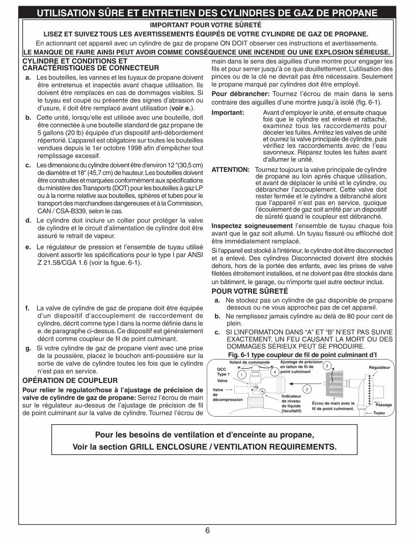
Fig. 6-1 type coupleur de fil de point culminant d’I
Valvede décompression
QCC Type 1
Valve
Ajustage de précision en laiton de fil de point culminant
Indicateur de niveau de liquide (facultatif)
Écrou de main avec le fil de point culminant.
Régulateur
Passage
Tuyau
Volant de commande
main dans le sens des aiguilles d’une montre pour engager les fils et pour serrer jusqu’à ce que douillettement. L’utilisation des pinces ou de la clé ne devrait pas être nécessaire. Seulement le propane marqué par cylindres doit être employé.Pour débrancher: Tournez l’écrou de main dans le sens contraire des aiguilles d’une montre jusqu’à isolé (fig. 6-1).
Important: Avant d’employer le unité, et ensuite chaque fois que le cylindre est enlevé et rattaché, examinez tous les raccordements pour déceler les fuites. Arrêtez les valves de unité et ouvrez la valve principale de cylindre, puis vérifiez les raccordements avec de l’eau savonneux. Réparez toutes les fuites avant d’allumer le unité.
ATTENTION: Tournez toujours la valve principale de cylindre de propane au loin après chaque utilisation, et avant de déplacer le unité et le cylindre, ou débrancher l’accouplement. Cette valve doit rester fermée et le cylindre a débranché alors que l’appareil n’est pas en service, quoique l’écoulement de gaz soit arrêté par un dispositif de sûreté quand le coupleur est débranché.
Inspectez soigneusement l’ensemble de tuyau chaque fois avant que le gaz soit allumé. Un tuyau fissuré ou effiloché doit être immédiatement remplacé.Si l'appareil est stocké à l'intérieur, le cylindre doit être disconnected et a enlevé. Des cylindres Disconnected doivent être stockés dehors, hors de la portée des enfants, avec les prises de valve filetées étroitement installées, et ne doivent pas être stockés dans un bâtiment, le garage, ou n'importe quel autre secteur inclus.POUR VOTRE SÛRETÉa. Ne stockez pas un cylindre de gaz disponible de propane
dessous ou ne vous approchez pas de cet appareil.b. Ne remplissez jamais cylindre au delà de 80 pour cent de
plein.c. SI L’INFORMATION DANS “A” ET “B” N’EST PAS SUIVIE
EXACTEMENT, UN FEU CAUSANT LA MORT OU DES DOMMAGES SÉRIEUX PEUT SE PRODUIRE.
IMPORTANT POUR VOTRE SÛRETÉLISEZ ET SUIVEZ TOUS LES AVERTISSEMENTS ÉQUIPÉS DE VOTRE CYLINDRE DE GAZ DE PROPANE.
En actionnant cet appareil avec un cylindre de gaz de propane ON DOIT observer ces instructions et avertissements. LE MANQUE DE FAIRE AINSI PEUT AVOIR COMME CONSÉQUENCE UNE INCENDIE OU UNE EXPLOSION SÉRIEUSE.CYLINDRE ET CONDITIONS ET CARACTÉRISTIQUES DE CONNECTEURa. Les bouteilles, les vannes et les tuyaux de propane doivent
être entretenus et inspectés avant chaque utilisation. Ils doivent être remplacés en cas de dommages visibles. Si le tuyau est coupé ou présente des signes d’abrasion ou d’usure, il doit être remplacé avant utilisation (voir e.).
b. Cette unité, lorsqu'elle est utilisée avec une bouteille, doit être connectée à une bouteille standard de gaz propane de 5 gallons (20 lb) équipée d'un dispositif anti-débordement répertorié. L’appareil est obligatoire sur toutes les bouteilles vendues depuis le 1er octobre 1998 afin d’empêcher tout remplissage excessif.
c. Les dimensions du cylindre doivent être d'environ 12 "(30,5 cm) de diamètre et 18" (45,7 cm) de hauteur. Les bouteilles doivent être construites et marquées conformément aux spécifications du ministère des Transports (DOT) pour les bouteilles à gaz LP ou à la norme relative aux bouteilles, sphères et tubes pour le transport des marchandises dangereuses et à la Commission, CAN / CSA-B339, selon le cas.
d. Le cylindre doit inclure un collier pour protéger la valve de cylindre et le circuit d’alimentation de cylindre doit être assuré le retrait de vapeur.
e. Le montage du régulateur de pression et le flexible (Fig. 6-1) fourni avec cet appareil au gaz en plein air (modèles au propane seulement) doit être utilisé. Assemblées d'origine et régulateur de pression et le tuyau de remplacement doivent être ceux spécifiés par le fabricant pour le raccordement d'un dispositif de cylindre de liaison identifiée comme de type I par le ANSI Z 21.58/CGA 1.6 (voir liste des pièces pour les informations de commande).
f. La valve de cylindre de gaz de propane doit être équipée d’un dispositif d’accouplement de raccordement de cylindre, décrit comme type I dans la norme définie dans le e. de paragraphe ci-dessus. Ce dispositif est généralement décrit comme coupleur de fil de point culminant.
g. Si votre cylindre de gaz de propane vient avec une prise de la poussière, placez le bouchon anti-poussière sur la sortie de valve de cylindre toutes les fois que le cylindre n’est pas en service.
OPÉRATION DE COUPLEURPour relier le regulator/hose à l’ajustage de précision de valve de cylindre de gaz de propane: Serrez l’écrou de main sur le régulateur au-dessus de l’ajustage de précision de fil de point culminant sur la valve de cylindre. Tournez l’écrou de
1
2
3
4
e. Le régulateur de pression et l’ensemble de tuyau utilisé doivent assortir les spécifications pour le type I par ANSI Z 21.58/CGA 1.6 (voir la figue. 6-1).
Pour les besoins de ventilation et d'enceinte au propane,
Voir la section GRILL ENCLOSURE / VENTILATION REQUIREMENTS.
UTILISATION SÛRE ET ENTRETIEN DES CYLINDRES DE GAZ DE PROPANE
7
U�L�
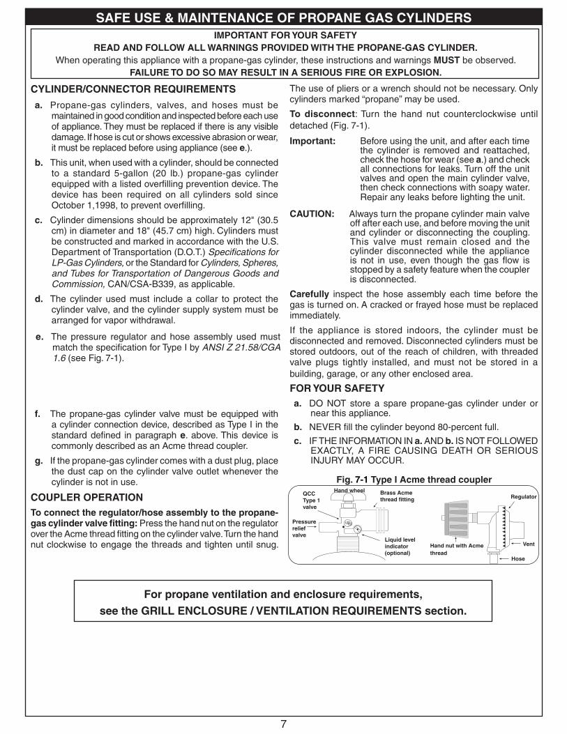
Fig. 7-1 Type I Acme thread coupler
Pressure relief valve
QCC Type 1 valve
Brass Acme thread fitting
Liquid level indicator (optional)
Hand nut with Acme thread
Regulator
Vent
Hose
Hand wheel
The use of pliers or a wrench should not be necessary. Only cylinders marked “propane” may be used.
To disconnect: Turn the hand nut counterclockwise until detached (Fig. 7-1).
Important: Before using the unit, and after each time the cylinder is removed and reattached, check the hose for wear (see a.) and check all connections for leaks. Turn off the unit valves and open the main cylinder valve, then check connections with soapy water. Repair any leaks before lighting the unit.
CAUTION: Always turn the propane cylinder main valve off after each use, and before moving the unit and cylinder or disconnecting the coupling. This valve must remain closed and the cylinder disconnected while the appliance is not in use, even though the gas flow is stopped by a safety feature when the coupler is disconnected.
Carefully inspect the hose assembly each time before the gas is turned on. A cracked or frayed hose must be replaced immediately.
If the appliance is stored indoors, the cylinder must be disconnected and removed. Disconnected cylinders must be stored outdoors, out of the reach of children, with threaded valve plugs tightly installed, and must not be stored in a building, garage, or any other enclosed area.
FOR YOUR SAFETYa. DO NOT store a spare propane-gas cylinder under or
near this appliance.
b. NEVER fill the cylinder beyond 80-percent full.
c. IF THE INFORMATION IN a. AND b. IS NOT FOLLOWED EXACTLY, A FIRE CAUSING DEATH OR SERIOUS INJURY MAY OCCUR.
IMPORTANT FOR YOUR SAFETYREAD AND FOLLOW ALL WARNINGS PROVIDED WITH THE PROPANE-GAS CYLINDER.
When operating this appliance with a propane-gas cylinder, these instructions and warnings MUST be observed.FAILURE TO DO SO MAY RESULT IN A SERIOUS FIRE OR EXPLOSION.
CYLINDER/CONNECTOR REQUIREMENTS
a. Propane-gas cylinders, valves, and hoses must be maintained in good condition and inspected before each use of appliance. They must be replaced if there is any visible damage. If hose is cut or shows excessive abrasion or wear, it must be replaced before using appliance (see e.).
b. This unit, when used with a cylinder, should be connected to a standard 5-gallon (20 lb.) propane-gas cylinder equipped with a listed overfilling prevention device. The device has been required on all cylinders sold since October 1,1998, to prevent overfilling.
c. Cylinder dimensions should be approximately 12" (30.5 cm) in diameter and 18" (45.7 cm) high. Cylinders must be constructed and marked in accordance with the U.S. Department of Transportation (D.O.T.) Specifications for LP-Gas Cylinders, or the Standard for Cylinders, Spheres, and Tubes for Transportation of Dangerous Goods and Commission, CAN/CSA-B339, as applicable.
d. The cylinder used must include a collar to protect the cylinder valve, and the cylinder supply system must be arranged for vapor withdrawal.
e. The pressure regulator and hose assembly (Fig. 7-1) supplied with this outdoor gas appliance (L.P. models only) must be used. Original and replacement pressure regulator and hose assemblies must be those specified by the manufacturer for connection with a cylinder connecting device identified as Type I by the ANSI Z 21.58/CGA 1.6 (see PARTS LIST for ordering information).
f. The propane-gas cylinder valve must be equipped with a cylinder connection device, described as Type I in the standard defined in paragraph e. above. This device is commonly described as an Acme thread coupler.
g. If the propane-gas cylinder comes with a dust plug, place the dust cap on the cylinder valve outlet whenever the cylinder is not in use.
COUPLER OPERATIONTo connect the regulator/hose assembly to the propane-gas cylinder valve fitting: Press the hand nut on the regulator over the Acme thread fitting on the cylinder valve. Turn the hand nut clockwise to engage the threads and tighten until snug.
e. The pressure regulator and hose assembly used must match the specification for Type I by ANSI Z 21.58/CGA 1.6 (see Fig. 7-1).
For propane ventilation and enclosure requirements,
see the GRILL ENCLOSURE / VENTILATION REQUIREMENTS section.
SAFE USE & MAINTENANCE OF PROPANE GAS CYLINDERS
8
Fig. 8-1 Ventilation detail
Min.90˚
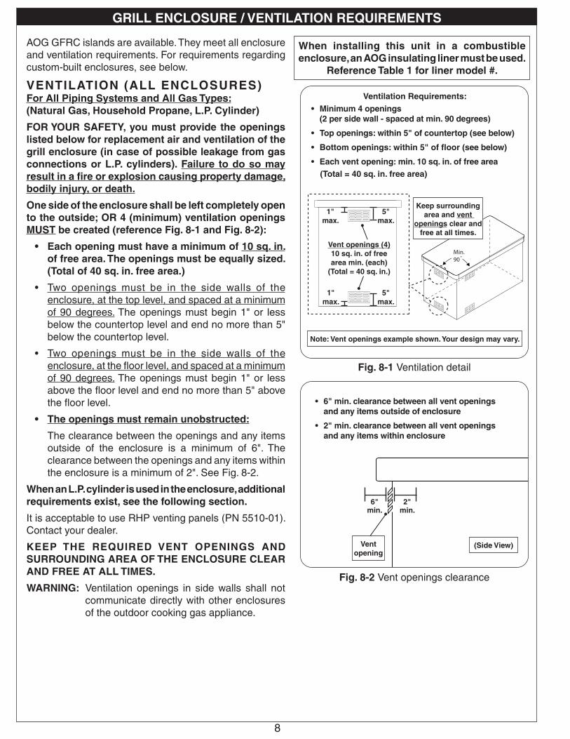
Ventilation Requirements:• Minimum 4 openings
(2 per side wall - spaced at min. 90 degrees)
• Top openings: within 5" of countertop (see below)
• Bottom openings: within 5" of floor (see below)
• Each vent opening: min. 10 sq. in. of free area(Total = 40 sq. in. free area)
1"max.
Keep surrounding area and vent
openings clear and free at all times.
5"max.
1"max.
5"max.
Vent openings (4)10 sq. in. of free area min. (each)
(Total = 40 sq. in.)
Note: Vent openings example shown. Your design may vary.
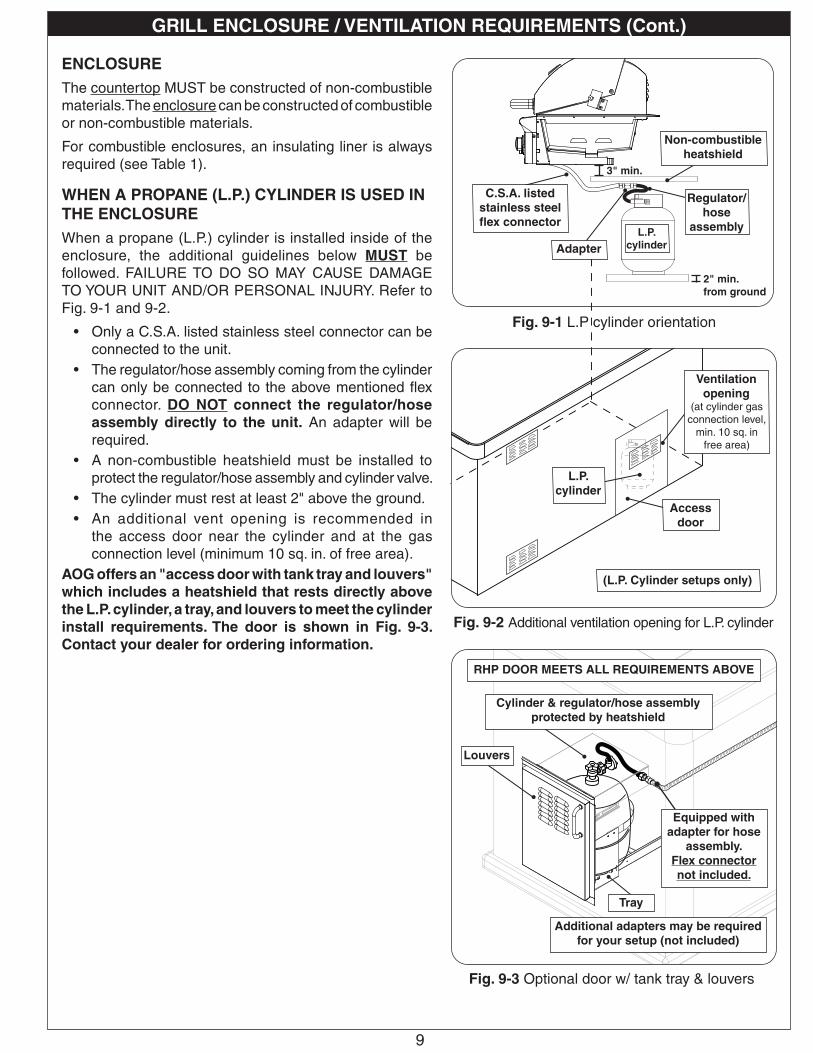
• 6" min. clearance between all vent openings and any items outside of enclosure
• 2" min. clearance between all vent openings and any items within enclosure
Fig. 8-2 Vent openings clearance
2"min.
(Side View)
6"min.
Vent opening
When installing this unit in a combustible enclosure, an AOG insulating liner must be used.
Reference Table 1 for liner model #.
AOG GFRC islands are available. They meet all enclosure and ventilation requirements. For requirements regarding custom-built enclosures, see below.
VENTILATION (ALL ENCLOSURES)For All Piping Systems and All Gas Types:(Natural Gas, Household Propane, L.P. Cylinder)
FOR YOUR SAFETY, you must provide the openings listed below for replacement air and ventilation of the grill enclosure (in case of possible leakage from gas connections or L.P. cylinders). Failure to do so may result in a fire or explosion causing property damage, bodily injury, or death.
One side of the enclosure shall be left completely open to the outside; OR 4 (minimum) ventilation openings MUST be created (reference Fig. 8-1 and Fig. 8-2):
• Each opening must have a minimum of 10 sq. in. of free area. The openings must be equally sized. (Total of 40 sq. in. free area.)
• Two openings must be in the side walls of the enclosure, at the top level, and spaced at a minimum of 90 degrees. The openings must begin 1" or less below the countertop level and end no more than 5" below the countertop level.
• Two openings must be in the side walls of the enclosure, at the floor level, and spaced at a minimum of 90 degrees. The openings must begin 1" or less above the floor level and end no more than 5" above the floor level.
• The openings must remain unobstructed:
The clearance between the openings and any items outside of the enclosure is a minimum of 6". The clearance between the openings and any items within the enclosure is a minimum of 2". See Fig. 8-2.
When an L.P. cylinder is used in the enclosure, additional requirements exist, see the following section.
It is acceptable to use RHP venting panels (PN 5510-01). Contact your dealer.
KEEP THE REQUIRED VENT OPENINGS AND SURROUNDING AREA OF THE ENCLOSURE CLEAR AND FREE AT ALL TIMES.
WARNING: Ventilation openings in side walls shall not communicate directly with other enclosures of the outdoor cooking gas appliance.
GRILL ENCLOSURE / VENTILATION REQUIREMENTS
9
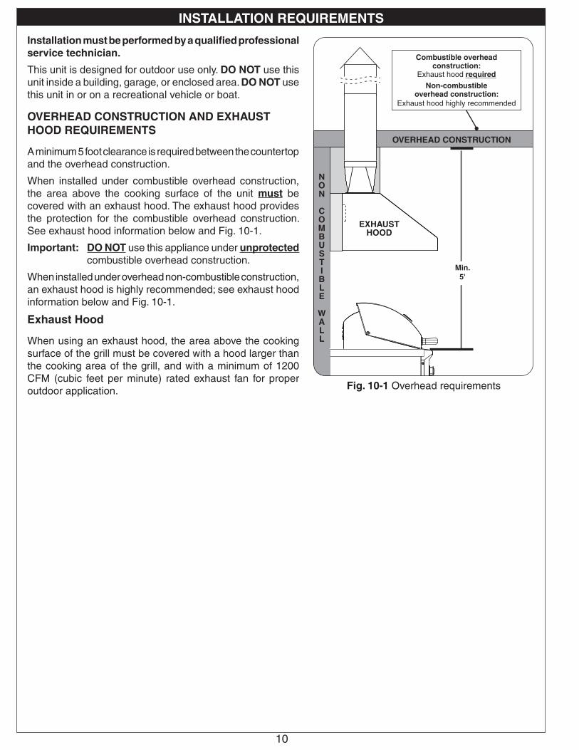
Fig. 9-3 Optional door w/ tank tray & louvers
Cylinder & regulator/hose assembly protected by heatshield
Additional adapters may be required for your setup (not included)
Equipped with adapter for hose
assembly.Flex connector not included.
Fig. 9-2 Additional ventilation opening for L.P. cylinder
RHP DOOR MEETS ALL REQUIREMENTS ABOVE
Access door
L.P. cylinder
Ventilation opening
(at cylinder gas connection level,
min. 10 sq. in free area)
(L.P. Cylinder setups only)
Louvers
Tray
ENCLOSUREThe countertop MUST be constructed of non-combustible materials. The enclosure can be constructed of combustible or non-combustible materials.
For combustible enclosures, an insulating liner is always required (see Table 1).
WHEN A PROPANE (L.P.) CYLINDER IS USED IN THE ENCLOSUREWhen a propane (L.P.) cylinder is installed inside of the enclosure, the additional guidelines below MUST be followed. FAILURE TO DO SO MAY CAUSE DAMAGE TO YOUR UNIT AND/OR PERSONAL INJURY. Refer to Fig. 9-1 and 9-2.
• Only a C.S.A. listed stainless steel connector can be connected to the unit.
• The regulator/hose assembly coming from the cylinder can only be connected to the above mentioned flex connector. DO NOT connect the regulator/hose assembly directly to the unit. An adapter will be required.
• A non-combustible heatshield must be installed to protect the regulator/hose assembly and cylinder valve.
• The cylinder must rest at least 2" above the ground.• An additional vent opening is recommended in
the access door near the cylinder and at the gas connection level (minimum 10 sq. in. of free area).
AOG offers an "access door with tank tray and louvers" which includes a heatshield that rests directly above the L.P. cylinder, a tray, and louvers to meet the cylinder install requirements. The door is shown in Fig. 9-3. Contact your dealer for ordering information.
Adapter
C.S.A. listed stainless steel flex connector
Non-combustible heatshield
Regulator/hose
assemblyL.P. cylinder
3" min.
2" min.from ground
Fig. 9-1 L.P cylinder orientation
GRILL ENCLOSURE / VENTILATION REQUIREMENTS (Cont.)
10
Installation must be performed by a qualified professional service technician.
This unit is designed for outdoor use only. DO NOT use this unit inside a building, garage, or enclosed area. DO NOT use this unit in or on a recreational vehicle or boat.
OVERHEAD CONSTRUCTION AND EXHAUST HOOD REQUIREMENTS
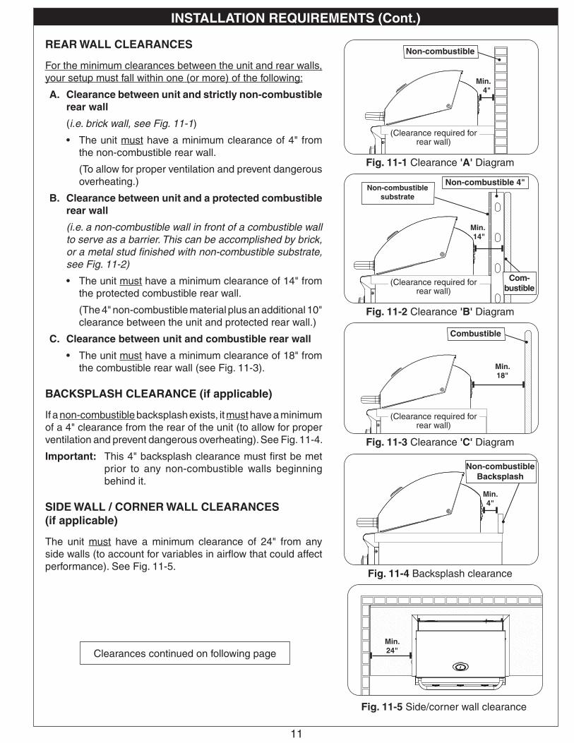
A minimum 5 foot clearance is required between the countertop and the overhead construction.
When installed under combustible overhead construction, the area above the cooking surface of the unit must be covered with an exhaust hood. The exhaust hood provides the protection for the combustible overhead construction. See exhaust hood information below and Fig. 10-1.
Important: DO NOT use this appliance under unprotected combustible overhead construction.
When installed under overhead non-combustible construction, an exhaust hood is highly recommended; see exhaust hood information below and Fig. 10-1.
Exhaust Hood
When using an exhaust hood, the area above the cooking surface of the grill must be covered with a hood larger than the cooking area of the grill, and with a minimum of 1200 CFM (cubic feet per minute) rated exhaust fan for proper outdoor application.
INSTALLATION REQUIREMENTS
Fig. 10-1 Overhead requirements
Min. 5'
OVERHEAD CONSTRUCTION
EXHAUST HOOD
Combustible overhead construction:
Exhaust hood requiredNon-combustible
overhead construction:Exhaust hood highly recommended
NON
COMBUSTIBLE
WALL
11
REAR WALL CLEARANCES
For the minimum clearances between the unit and rear walls, your setup must fall within one (or more) of the following:
A. Clearance between unit and strictly non-combustible rear wall
(i.e. brick wall, see Fig. 11-1)
• The unit must have a minimum clearance of 4" from the non-combustible rear wall.
(To allow for proper ventilation and prevent dangerous overheating.)
B. Clearance between unit and a protected combustible rear wall
(i.e. a non-combustible wall in front of a combustible wall to serve as a barrier. This can be accomplished by brick, or a metal stud finished with non-combustible substrate, see Fig. 11-2)
• The unit must have a minimum clearance of 14" from the protected combustible rear wall.
(The 4" non-combustible material plus an additional 10" clearance between the unit and protected rear wall.)
C. Clearance between unit and combustible rear wall
• The unit must have a minimum clearance of 18" from the combustible rear wall (see Fig. 11-3).
BACKSPLASH CLEARANCE (if applicable)
If a non-combustible backsplash exists, it must have a minimum of a 4" clearance from the rear of the unit (to allow for proper ventilation and prevent dangerous overheating). See Fig. 11-4.
Important: This 4" backsplash clearance must first be met prior to any non-combustible walls beginning behind it.
SIDE WALL / CORNER WALL CLEARANCES (if applicable)
The unit must have a minimum clearance of 24" from any side walls (to account for variables in airflow that could affect performance). See Fig. 11-5.
INSTALLATION REQUIREMENTS (Cont.)
Fig. 11-3 Clearance 'C' Diagram
Combustible
Min. 18"
(Clearance required for rear wall)
Fig. 11-4 Backsplash clearance
Non-combustible Backsplash
Min. 4"
Fig. 11-2 Clearance 'B' Diagram
Min. 14"
Non-combustible substrate
Non-combustible 4"
Com-bustible
(Clearance required for rear wall)
Fig. 11-1 Clearance 'A' Diagram
Non-combustible
Min. 4"
(Clearance required for rear wall)
Fig. 11-5 Side/corner wall clearance
Min. 24"Clearances continued on following page

12
CONTROL PANEL CLEARANCES
• The control panel MUST have a minimum side clearance of 6" from any obstructions/side walls. See Fig. 12-1.
(To allow for access to light switch and control panel removal.)
• The control panel MUST remain removable for servicing (see CONTROL PANEL REMOVAL section). Any adjacent countertops must not obstruct the panel from being removed.
COMBUSTION AIR AND COOLING AIRFLOW
Proper airflow (front-to-back, Fig. 12-2) MUST be maintained for the unit to perform as it was designed. If airflow is blocked, overheating and poor combustion will result. Do not block the 1" front air inlet along the bottom of the control panel.
CAUTION: Wind blowing into or across the rear oven lid vent (Fig. 12-4) can cause poor performance and/or dangerous overheating. Install the grill so that the prevailing wind blows toward the front of the grill (Fig. 12-3). A wind deflector is available for purchase to assist in proper airflow during windy conditions. See Table 1 for model numbers. Follow the instructions included with the wind deflector for installation.
GAS-SUPPLY PLUMBING REQUIREMENTS
For natural gas or a household propane system, rigid 1/2" or 3/4" black steel pipe or local code-approved pipe is required to conduct the gas supply to the unit. Contact your local gas supplier. Connect this pipe to the required C.S.A.-approved stainless-steel flex connector (attached). An NPT adapter has been provided for 1/2" pipe. DO NOT use a rubber hose within the unit enclosure. Apply only joint compounds that are resistant to all gasses on all NPT pipe fittings except flare fittings. Make sure to tighten all fittings securely.
Note: If 1/2" pipe is used with natural gas, it should be no longer than 20'.
Important: A shut-off valve (not included) in the gas line is required. It provides for safety when the unit is not in use and for convenient maintenance and repair. It must be installed within 6 feet of the unit. If it is located within the enclosure, it must be easily accessible. Use a pipe joint compound resistant to all gasses on all male fittings except flare fittings.
GAS SUPPLY AND MANIFOLD PRESSURES:For natural gas - normal 7" water column (w.c.), minimum 5", maximum 10 1/2". For propane gas - normal 11" w.c., minimum 10", maximum 13".
INSTALLATION REQUIREMENTS (Cont.)
CORRECT
PLACE GRILL SO PREVAILING WIND BLOWS TOWARD FRONT OF GRILL
Fig. 12-3 Airflow direction - CORRECT
Fig. 12-2 Airflow diagram
YOU MUST PROTECT REAR OVEN VENT FROM PREVAILING WIND
Rear oven lid vent
INCORRECT
Fig. 12-4 Airflow direction - INCORRECT
(1" front air inlet)
Fig. 12-1 Control panel clearances
Min. 6"
Min. 6"
13
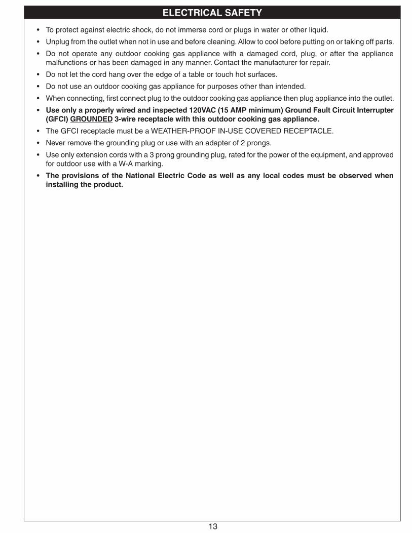
• To protect against electric shock, do not immerse cord or plugs in water or other liquid.
• Unplug from the outlet when not in use and before cleaning. Allow to cool before putting on or taking off parts.
• Do not operate any outdoor cooking gas appliance with a damaged cord, plug, or after the appliance malfunctions or has been damaged in any manner. Contact the manufacturer for repair.
• Do not let the cord hang over the edge of a table or touch hot surfaces.
• Do not use an outdoor cooking gas appliance for purposes other than intended.
• When connecting, first connect plug to the outdoor cooking gas appliance then plug appliance into the outlet.
• Use only a properly wired and inspected 120VAC (15 AMP minimum) Ground Fault Circuit Interrupter (GFCI) GROUNDED 3-wire receptacle with this outdoor cooking gas appliance.
• The GFCI receptacle must be a WEATHER-PROOF IN-USE COVERED RECEPTACLE.
• Never remove the grounding plug or use with an adapter of 2 prongs.
• Use only extension cords with a 3 prong grounding plug, rated for the power of the equipment, and approved for outdoor use with a W-A marking.
• The provisions of the National Electric Code as well as any local codes must be observed when installing the product.
ELECTRICAL SAFETY
14
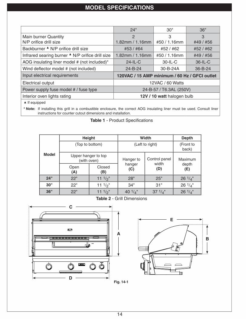
Model
Height Width Depth
(Top to bottom) (Left to right) (Front to back)
Upper hanger to top(with oven) Hanger to
hanger(C)
Control panelwidth(D)
Maximum depth
(E)Open(A)
Closed(B)
24" 22" 11 1/2" 28" 25" 26 1/4"30" 22" 11 1/2" 34" 31" 26 1/4"36" 22" 11 1/2" 40 1/4" 37 1/4" 26 1/4"
E
BA
C
DFig. 14-1
MODEL SPECIFICATIONS
Table 2 - Grill Dimensions
24" 30" 36"
Main burner Quantity N/P orifice drill size
2 1.82mm / 1.16mm
3 #50 / 1.16mm
3 #49 / #56
Backburner ▲ N/P orifice drill size #53 / #64 #52 / #62 #52 / #62
Infrared searing burner ▲ N/P orifice drill size 1.82mm / 1.16mm #50 / 1.16mm #49 / #56
AOG insulating liner model # (not included)* 24-IL-C 30-IL-C 36-IL-C
Wind deflector model # (not included) 24-B-24 30-B-24A 36-B-24
Input electrical requirements 120VAC / 15 AMP minimum / 60 Hz / GFCI outlet
Electrical output 12VAC / 60 Watts
Power supply fuse model # / fuse type 24-B-57 / T6.3AL (250V)
Interior oven lights rating 12V / 10 watt halogen bulb▲ If equipped
* Note: If installing this grill in a combustible enclosure, the correct AOG insulating liner must be used. Consult liner instructions for counter cutout dimensions and installation.
Table 1 - Product Specifications
15
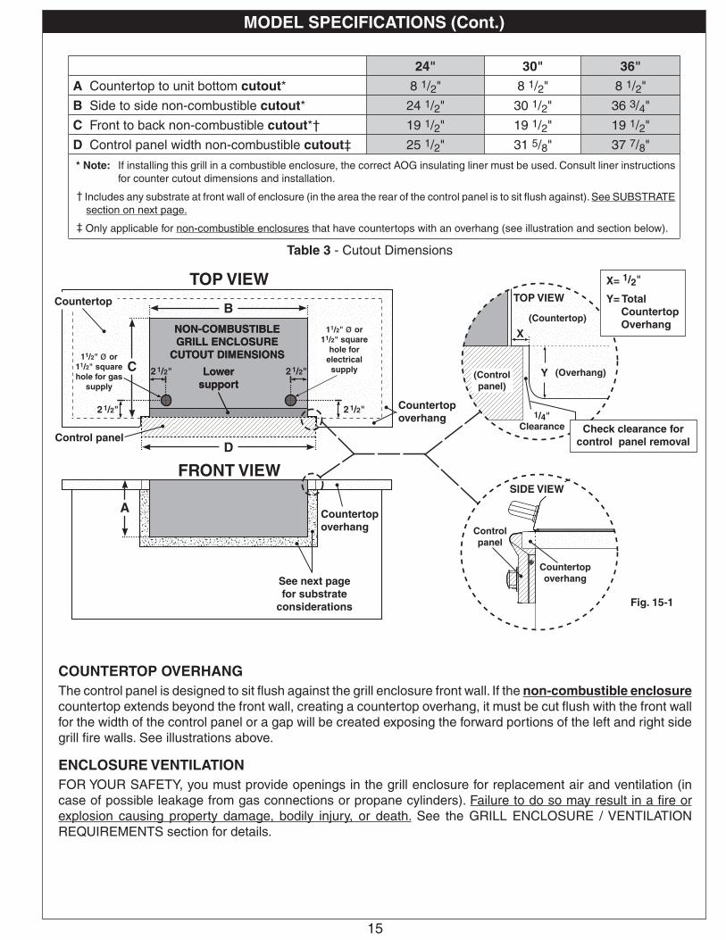
COUNTERTOP OVERHANGThe control panel is designed to sit flush against the grill enclosure front wall. If the non-combustible enclosure countertop extends beyond the front wall, creating a countertop overhang, it must be cut flush with the front wall for the width of the control panel or a gap will be created exposing the forward portions of the left and right side grill fire walls. See illustrations above.
ENCLOSURE VENTILATIONFOR YOUR SAFETY, you must provide openings in the grill enclosure for replacement air and ventilation (in case of possible leakage from gas connections or propane cylinders). Failure to do so may result in a fire or explosion causing property damage, bodily injury, or death. See the GRILL ENCLOSURE / VENTILATION REQUIREMENTS section for details.
TOP VIEWCountertop
Countertop overhang
Control panel
Fig. 15-1
FRONT VIEW
B
C
D
See next page for substrate
considerations
Countertop overhang
X
TOP VIEW
SIDE VIEW
Countertop overhang
(Control panel)
(Countertop)
Y
1/4"Clearance
(Overhang)
X= 1/2"
Y= Total Countertop Overhang
A
Control panel
Check clearance for control panel removal
24" 30" 36"
A Countertop to unit bottom cutout* 8 1/2" 8 1/2" 8 1/2"
B Side to side non-combustible cutout* 24 1/2" 30 1/2" 36 3/4"
C Front to back non-combustible cutout*† 19 1/2" 19 1/2" 19 1/2"
D Control panel width non-combustible cutout‡ 25 1/2" 31 5/8" 37 7/8"
* Note: If installing this grill in a combustible enclosure, the correct AOG insulating liner must be used. Consult liner instructions for counter cutout dimensions and installation.
† Includes any substrate at front wall of enclosure (in the area the rear of the control panel is to sit flush against). See SUBSTRATE section on next page.
‡ Only applicable for non-combustible enclosures that have countertops with an overhang (see illustration and section below).
MODEL SPECIFICATIONS (Cont.)
Table 3 - Cutout Dimensions
2 1/2"
2 1/2"
11/2" ø or 11/2" square
hole for electrical
supply Lower support
NON-COMBUSTIBLE GRILL ENCLOSURE
CUTOUT DIMENSIONS
2 1/2"
2 1/2"
11/2" ø or 11/2" square hole for gas
supply
11/2" ø or 11/2" square hole for gas
supply
Lower support
NON-COMBUSTIBLE GRILL ENCLOSURE
CUTOUT DIMENSIONS
16
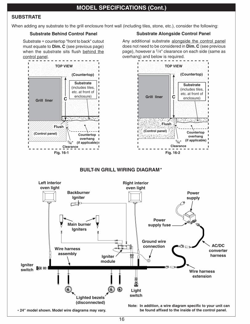
SUBSTRATE
When adding any substrate to the grill enclosure front wall (including tiles, stone, etc.), consider the following:
Substrate Behind Control Panel Substrate Alongside Control Panel
C C
Flush(Control panel)
(Countertop) (Countertop)
(Control panel)
Substrate(includes tiles, etc. at front of
enclosure)
Countertop overhang
(if applicable)
Flush
Grill linerGrill liner
Substrate(includes tiles, etc. at front of
enclosure)
1/4"Clearance
Any additional substrate alongside the control panel does not need to be considered in Dim. C (see previous page), however a 1/4" clearance on each side (same as overhang) and below is required.
Substrate + countertop "front to back" cutout must equate to Dim. C (see previous page) when the substrate sits flush behind the control panel.
Fig. 16-1 Fig. 16-2
Countertop overhang
(if applicable)1/4"Clearance
TOP VIEW TOP VIEW
MODEL SPECIFICATIONS (Cont.)
Note: In addition, a wire diagram specific to your unit can be found affixed to the inside of the control panel.
BUILT-IN GRILL WIRING DIAGRAM
* 24" model shown. Model wire diagrams may vary.
*
Power supply
Wire harness extension
Right interior oven light
Left interior oven light
Main burner Igniters
Backburner Igniter
Igniter module
Igniter switch
Light switchLighted bezels
(disconnected)
Power supply fuse
AC/DC converter harness
Wire harness assembly
Ground wire connection
17
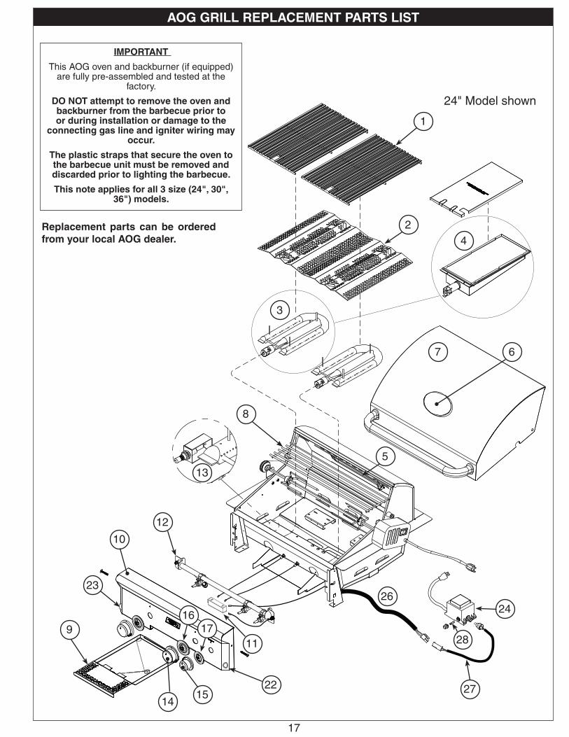
IMPORTANT
This AOG oven and backburner (if equipped) are fully pre-assembled and tested at the
factory.
DO NOT attempt to remove the oven and backburner from the barbecue prior to or during installation or damage to the
connecting gas line and igniter wiring may occur.
The plastic straps that secure the oven to the barbecue unit must be removed and discarded prior to lighting the barbecue.
This note applies for all 3 size (24", 30", 36") models.
Replacement parts can be ordered from your local AOG dealer.
AOG GRILL REPLACEMENT PARTS LIST
24" Model shown
1
2
3
4
5
67
8
9
10
22
12
13
1415
23
11
2426
1617
27
28
18
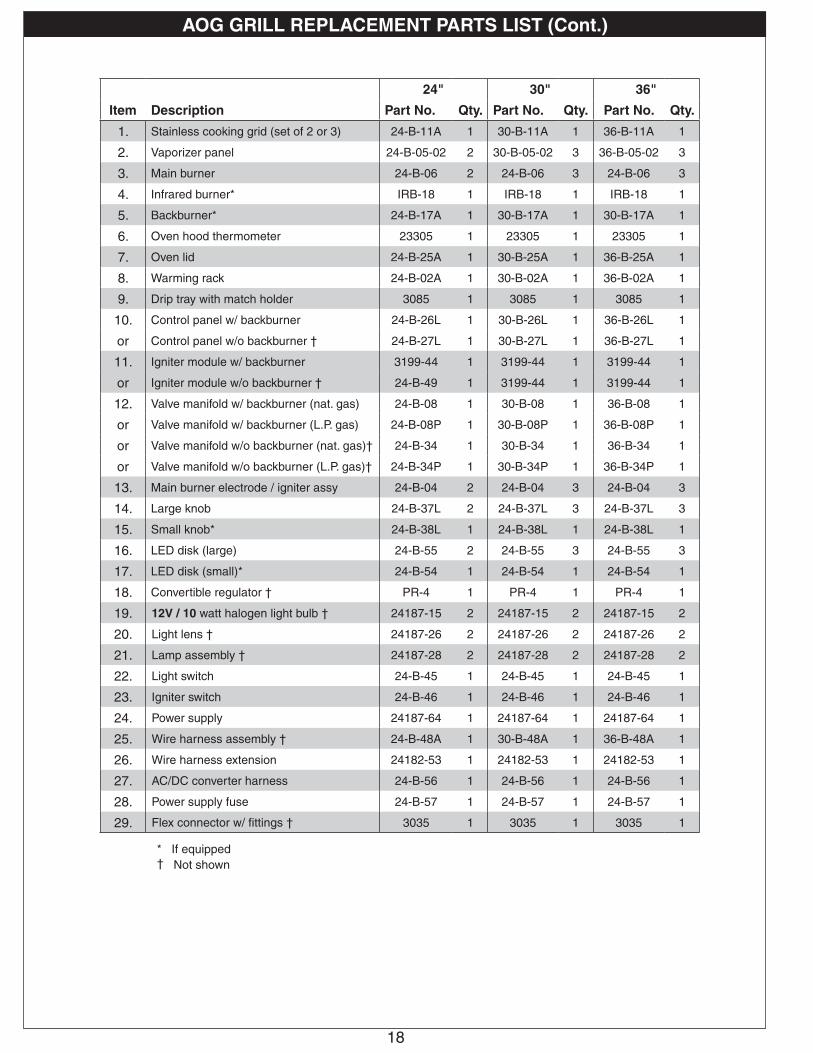
AOG GRILL REPLACEMENT PARTS LIST (Cont.)
24" 30" 36"
Item Description Part No. Qty. Part No. Qty. Part No. Qty.
1. Stainless cooking grid (set of 2 or 3) 24-B-11A 1 30-B-11A 1 36-B-11A 1
2. Vaporizer panel 24-B-05-02 2 30-B-05-02 3 36-B-05-02 3
3. Main burner 24-B-06 2 24-B-06 3 24-B-06 3
4. Infrared burner* IRB-18 1 IRB-18 1 IRB-18 1
5. Backburner* 24-B-17A 1 30-B-17A 1 30-B-17A 1
6. Oven hood thermometer 23305 1 23305 1 23305 1
7. Oven lid 24-B-25A 1 30-B-25A 1 36-B-25A 1
8. Warming rack 24-B-02A 1 30-B-02A 1 36-B-02A 1
9. Drip tray with match holder 3085 1 3085 1 3085 1
10. Control panel w/ backburner 24-B-26L 1 30-B-26L 1 36-B-26L 1
or Control panel w/o backburner † 24-B-27L 1 30-B-27L 1 36-B-27L 1
11. Igniter module w/ backburner 3199-44 1 3199-44 1 3199-44 1
or Igniter module w/o backburner † 24-B-49 1 3199-44 1 3199-44 1
12. Valve manifold w/ backburner (nat. gas) 24-B-08 1 30-B-08 1 36-B-08 1
or Valve manifold w/ backburner (L.P. gas) 24-B-08P 1 30-B-08P 1 36-B-08P 1
or Valve manifold w/o backburner (nat. gas)† 24-B-34 1 30-B-34 1 36-B-34 1
or Valve manifold w/o backburner (L.P. gas)† 24-B-34P 1 30-B-34P 1 36-B-34P 1
13. Main burner electrode / igniter assy 24-B-04 2 24-B-04 3 24-B-04 3
14. Large knob 24-B-37L 2 24-B-37L 3 24-B-37L 3
15. Small knob* 24-B-38L 1 24-B-38L 1 24-B-38L 1
16. LED disk (large) 24-B-55 2 24-B-55 3 24-B-55 3
17. LED disk (small)* 24-B-54 1 24-B-54 1 24-B-54 1
18. Convertible regulator † PR-4 1 PR-4 1 PR-4 1
19. 12V / 10 watt halogen light bulb † 24187-15 2 24187-15 2 24187-15 2
20. Light lens † 24187-26 2 24187-26 2 24187-26 2
21. Lamp assembly † 24187-28 2 24187-28 2 24187-28 2
22. Light switch 24-B-45 1 24-B-45 1 24-B-45 1
23. Igniter switch 24-B-46 1 24-B-46 1 24-B-46 1
24. Power supply 24187-64 1 24187-64 1 24187-64 1
25. Wire harness assembly † 24-B-48A 1 30-B-48A 1 36-B-48A 1
26. Wire harness extension 24182-53 1 24182-53 1 24182-53 1
27. AC/DC converter harness 24-B-56 1 24-B-56 1 24-B-56 1
28. Power supply fuse 24-B-57 1 24-B-57 1 24-B-57 1
29. Flex connector w/ fittings † 3035 1 3035 1 3035 1
* If equipped† Not shown
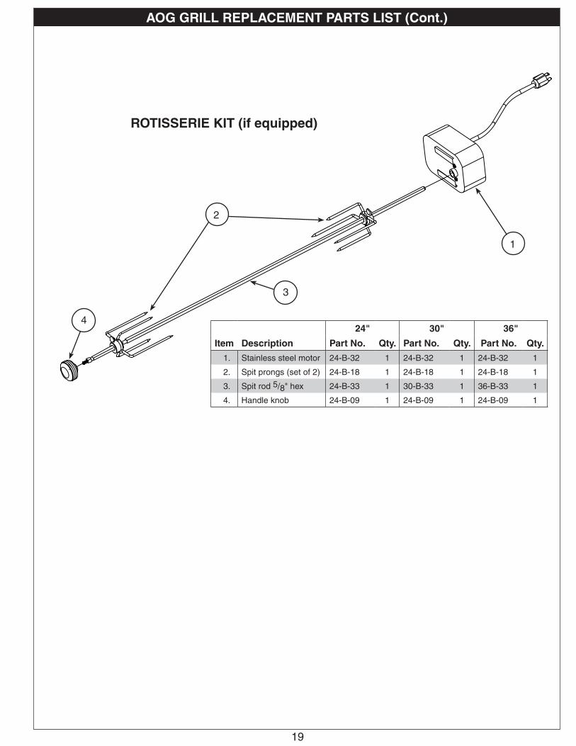
19
24" 30" 36"
Item Description Part No. Qty. Part No. Qty. Part No. Qty.
1. Stainless steel motor 24-B-32 1 24-B-32 1 24-B-32 1
2. Spit prongs (set of 2) 24-B-18 1 24-B-18 1 24-B-18 1
3. Spit rod 5/8" hex 24-B-33 1 30-B-33 1 36-B-33 1
4. Handle knob 24-B-09 1 24-B-09 1 24-B-09 1
2
4
1
3
AOG GRILL REPLACEMENT PARTS LIST (Cont.)
ROTISSERIE KIT (if equipped)
20
It is not required to remove the control panel or knobs to install this unit.
DO NOT lift the unit from the control panel when installing.
COUNTER PREPARATION
Consult Table 3 for non-combustible enclosure cutout dimensions. An AOG insulating liner must be used if any supporting construction is combustible. Consult the instructions that come with the liner for dimensions and additional installation information before beginning the installation.
This outdoor built-in grill must be supported by the stainless-steel hanger extending from the upper portion of the grill. The hanger rests on the left, right, and back of the countertop.
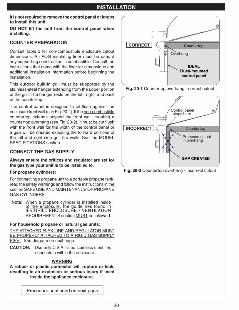
The control panel is designed to sit flush against the enclosure front wall (see Fig. 20-1). If the non-combustible countertop extends beyond the front wall, creating a countertop overhang (see Fig. 20-2), it must be cut flush with the front wall for the width of the control panel or a gap will be created exposing the forward portions of the left and right side grill fire walls. See the MODEL SPECIFICATIONS section.
CONNECT THE GAS SUPPLY
Always ensure the orifices and regulator are set for the gas type your unit is to be installed to.
For propane cylinders:
For connecting a propane unit to a portable propane tank, read the safety warnings and follow the instructions in the section SAFE USE AND MAINTENANCE OF PROPANE GAS CYLINDERS.
Note: When a propane cylinder is installed inside of the enclosure, the guidelines found in the GRILL ENCLOSURE / VENTILATION REQUIREMENTS section MUST be followed.
For household propane or natural gas units:
THE ATTACHED FLEX LINE AND REGULATOR MUST BE PROPERLY ATTACHED TO A RIGID GAS SUPPLY PIPE . See diagram on next page.
CAUTION: Use only C.S.A. listed stainless-steel flex connectors within the enclosure.
WARNINGA rubber or plastic connector will rupture or leak, resulting in an explosion or serious injury if used
inside the appliance enclosure.
GAP CREATED
IDEAL Flush-mounted control panel
Proposed cutout in overhang
Countertop
Countertop
Overhang
Control panel stops here
INSTALLATION
CORRECT
INCORRECT
Fig. 20-2 Countertop overhang - incorrect cutout
Fig. 20-1 Countertop overhang - correct cutout
Procedure continued on next page
INSTALLATION
21
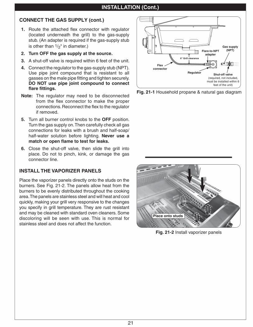
CONNECT THE GAS SUPPLY (cont.)
1. Route the attached flex connector with regulator (located underneath the grill) to the gas-supply stub. (An adapter is required if the gas-supply stub is other than 1/2" in diameter.)
2. Turn OFF the gas supply at the source.
3. A shut-off valve is required within 6 feet of the unit.
4. Connect the regulator to the gas-supply stub (NPT). Use pipe joint compound that is resistant to all gasses on the male pipe fitting and tighten securely. DO NOT use pipe joint compound to connect flare fittings.
Note: The regulator may need to be disconnected from the flex connector to make the proper connections. Reconnect the flex to the regulator if removed.
5. Turn all burner control knobs to the OFF position. Turn the gas supply on. Then carefully check all gas connections for leaks with a brush and half-soap/half-water solution before lighting. Never use a match or open flame to test for leaks.
6. Close the shut-off valve, then slide the grill into place. Do not to pinch, kink, or damage the gas connector line.
INSTALL THE VAPORIZER PANELS
Place the vaporizer panels directly onto the studs on the burners. See Fig. 21-2. The panels allow heat from the burners to be evenly distributed throughout the cooking area. The panels are stainless steel and will heat and cool quickly, making your grill very responsive to the changes you specify in grill temperature. They are rust resistant and may be cleaned with standard oven cleaners. Some discoloring will be seen with use. This is normal for stainless steel and does not affect the function.
Flex connector
Flare-to-NPT adapter
Regulator
6" Grill clearance
Gas supply (NPT)
INSTALLATION (Cont.)
Fig. 21-1 Household propane & natural gas diagram
Shut-off valve(required, not included,
must be installed within 6 feet of the unit)
Fig. 21-2 Install vaporizer panels
Place onto studs
22
INSTALLATION (Cont.)
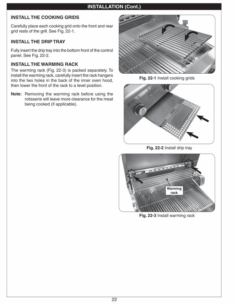
INSTALL THE COOKING GRIDS
Carefully place each cooking grid onto the front and rear grid rests of the grill. See Fig. 22-1.
INSTALL THE DRIP TRAY
Fully insert the drip tray into the bottom front of the control panel. See Fig. 22-2.
INSTALL THE WARMING RACKThe warming rack (Fig. 22-3) is packed separately. To install the warming rack, carefully insert the rack hangers into the two holes in the back of the inner oven hood, then lower the front of the rack to a level position.
Note: Removing the warming rack before using the rotisserie will leave more clearance for the meat being cooked (if applicable).
Warming rack
Fig. 22-3 Install warming rack
Fig. 22-1 Install cooking grids
Fig. 22-2 Install drip tray
23
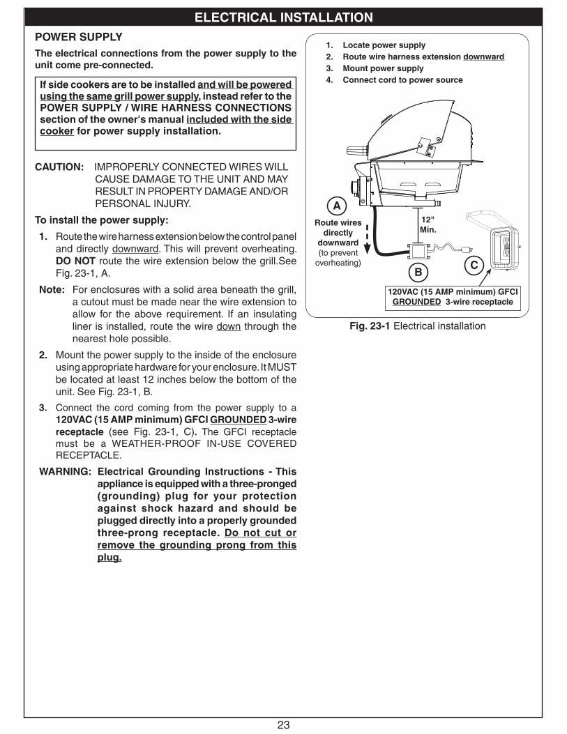
POWER SUPPLYThe electrical connections from the power supply to the unit come pre-connected.
CAUTION: IMPROPERLY CONNECTED WIRES WILL CAUSE DAMAGE TO THE UNIT AND MAY RESULT IN PROPERTY DAMAGE AND/OR PERSONAL INJURY.
To install the power supply:
1. Route the wire harness extension below the control panel and directly downward. This will prevent overheating. DO NOT route the wire extension below the grill.See Fig. 23-1, A.
Note: For enclosures with a solid area beneath the grill, a cutout must be made near the wire extension to allow for the above requirement. If an insulating liner is installed, route the wire down through the nearest hole possible.
2. Mount the power supply to the inside of the enclosure using appropriate hardware for your enclosure. It MUST be located at least 12 inches below the bottom of the unit. See Fig. 23-1, B.
3. Connect the cord coming from the power supply to a 120VAC (15 AMP minimum) GFCI GROUNDED 3-wire receptacle (see Fig. 23-1, C). The GFCI receptacle must be a WEATHER-PROOF IN-USE COVERED RECEPTACLE.
WARNING: Electrical Grounding Instructions - This appliance is equipped with a three-pronged (grounding) plug for your protection against shock hazard and should be plugged directly into a properly grounded three-prong receptacle. Do not cut or remove the grounding prong from this plug.
If side cookers are to be installed and will be powered using the same grill power supply, instead refer to the POWER SUPPLY / WIRE HARNESS CONNECTIONS section of the owner's manual included with the side cooker for power supply installation.
Fig. 23-1 Electrical installation
12"Min.
Route wires directly
downward(to prevent
overheating)
1. Locate power supply2. Route wire harness extension downward3. Mount power supply4. Connect cord to power source
120VAC (15 AMP minimum) GFCI GROUNDED 3-wire receptacle
A
BC
ELECTRICAL INSTALLATION
24
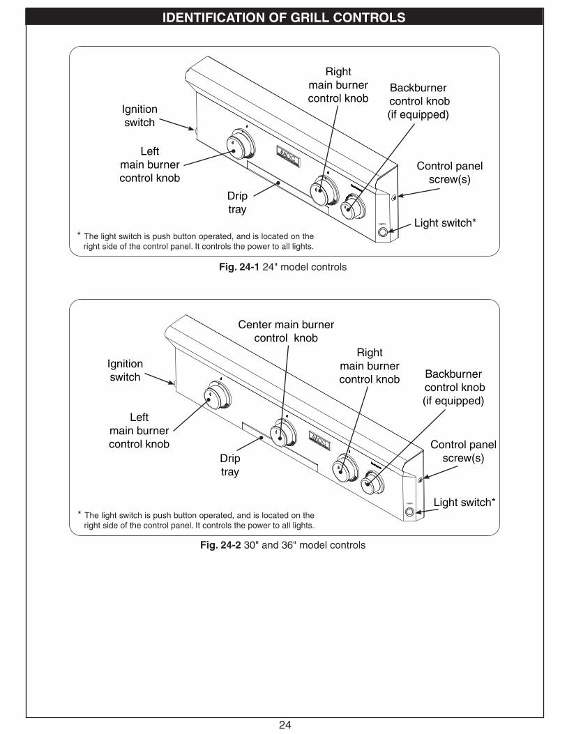
Left main burner control knob
Right main burner control knob
Backburner control knob (if equipped)
Center main burner control knob
Control panel screw(s)
Drip tray
Ignition switch
Left main burner control knob
Right main burner control knob Backburner
control knob (if equipped)
Control panel screw(s)Drip
tray
Ignition switch
Fig. 24-1 24" model controls
Fig. 24-2 30" and 36" model controls
Light switch** The light switch is push button operated, and is located on the
right side of the control panel. It controls the power to all lights.
* The light switch is push button operated, and is located on the right side of the control panel. It controls the power to all lights.
Light switch*
IDENTIFICATION OF GRILL CONTROLS
USE, CARE, & SERVICE
25
BEFORE INITIAL USEEnsure that:
• the unit has been properly installed and leak tested by a qualified professional service technician and as instructed in this manual.
• you have read and understand all of the information in this manual.
BEFORE EACH USEEnsure that:
• you smell around the appliance area for gas. If you smell gas (and all control knobs are in the OFF position), immediately shut off the gas supply and contact a qualified professional service technician or the gas supplier for inspection.
• the required vent openings and surrounding area of the enclosure are clear at all times.
• the cooking area and drip tray are clean, and the drip tray is properly installed.
• you inspect all piping and hoses for damage, cuts, wear, and tear. Replace any damaged components prior to use.
OPERATION• The unit becomes HOT during use. NEVER touch any part of the cooking area or surrounding hot surfaces with bare
hands. Use long-handled insulated BBQ tools and wear an insulated glove / oven mitt.
• Always keep your face and body as far from the unit as possible during use. Avoid wearing loose-fitting clothing as they could ignite.
• NEVER leave the unit unattended during use.
• NEVER cover more than 75% of the cooking surface with griddles or pans to prevent overheating.
• After each use, turn the control knob(s) to the OFF position and turn off the gas supply to the unit.
After reading and understanding all bullets above, follow these steps to light and use your grill:
1. Light the grill per the LIGHTING INSTRUCTIONS section.
2. Turn the control knobs to the HI-LIGHT position, close the hood, and allow the grill to preheat for 15 minutes or until desired cooking temperature is reached.
3. Place the food on the grill and cook as desired. Monitor the flames and the temperature, and adjust the heat setting if necessary.
4. See the sections below and the following pages for all other information regarding use.
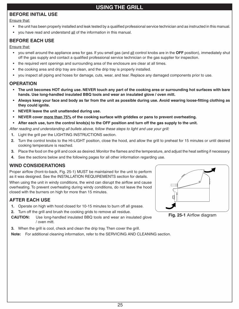
WIND CONSIDERATIONSProper airflow (front-to-back, Fig. 25-1) MUST be maintained for the unit to perform as it was designed. See the INSTALLATION REQUIREMENTS section for details.
When using the unit in windy conditions, the wind can disrupt the airflow and cause overheating. To prevent overheating during windy conditions, do not leave the hood closed with the burners on high for more than 15 minutes.
AFTER EACH USE1. Operate on high with hood closed for 10-15 minutes to burn off all grease.
2. Turn off the grill and brush the cooking grids to remove all residue.CAUTION: Use long-handled insulated BBQ tools and wear an insulated glove
/ oven mitt.
3. When the grill is cool, check and clean the drip tray. Then cover the grill.
Note: For additional cleaning information, refer to the SERVICING AND CLEANING section.
Fig. 25-1 Airflow diagram
USING THE GRILL
26
ARRÊT DU UNITÉ
Pour couper le unité, diminuez chaque bouton de commande de valve et tout en pressant tour il dans le sens des aiguilles d’une montre à la position de repos.
Fermez toujours la valve de la fourniture de gaz après chaque utilisation du unité.
ÉCLAIRAGE ÉLECTRONIQUE
Note: L’éclairage électronique exige une batterie installée de 9 volts avec une bonne charge.
1. Ouvrez les couvercles ou enlevez les couvertures des brûleurs pour être Lit.
2. Tournez tous les boutons de commande de gaz à leurs positions de repos.
3. Allumez le gaz à sa source.
Note: N’ouvrez pas p lus d ’une va lve à la fo is pour l ’éclairage électronique ou manuel.
4. Appuyez sur le bouton de commande souhaité pendant 5 secondes. Assurez-vous que l’allumeur brille (à l’intérieur du tube d’éclairage), puis tout en appuyant, tournez le bouton dans le sens inverse des aiguilles d’une montre jusqu’à la position HI LIGHT. Une fois le brûleur allumé, relâchez le bouton.
ATTENTION : Si un brûleur ne s’allume pas dans cinq (5) secondes d’allumer le bouton de commande, enfoncez le bouton et tournez-le à la position de repos. ATTENDEZ CINQ (5) MINUTES avant de répéter l’étape 4. Si vous sentez le gaz, suivez les instructions sur la couverture de ce manuel. Si les brûleurs ne s’allument toujours pas après que plusieurs tentatives, se rapportent aux instructions pour l’éclairage manuel.
5. Répétez l’étape 4 pour que chaque brûleur additionnel soit Lit.
Lisez toutes les instructions avant l’allumage, et suivez ces instructions chaque fois vous lumière le unité.
Fig. 26-2 - Éclairage manuel
Plus léger
Tube d’éclairage
EN EMPLOYANT UN RÉSERVOIR DE PROPANE PORTATIF
Des réservoirs de propane sont équipés d’un dispositif d’arrêt de sûreté qui peut ne pas causer le bas ou aucunes pression de gaz/flamme aux brûleurs si le fonctionnement et l’allumage des instructions ne sont pas suivis exactement (voir la note importante dans la section de dépannage pour plus de détails.)
ÉCLAIRAGE MANUEL
ATTENTION: Attendez toujours cinq (5) minutes le gaz pour se dégager après que n’importe quelle tentative non réussie d’éclairage.
1. Suivez les étapes 1 à 3 (à gauche).
2. Passez un allumeur brûlant de butane de long-baril ou une allumette brûlante de long-tige dans la grille à cuire s’ouvrant au dessus du tube d’éclairage. (Fig. 26-2). Pour des backburners, tenez la flamme contre le surface du backburner. Pour des sideburners, tenez la flamme contre le brûleur.
3. Vieux match / flamme d’un briquet à la partie supérieure du tube d’éclairage pendant 5 secondes, ou, à côté de la brûleur latéral / veilleuse. Puis appuyer sur le bouton de contrôle approprié et en appuyant tourner dans le sens antihoraire à la position HI LIGHT. Retirez le briquet ou des allumettes quand le brûleur s’allume, puis relâchez le bouton de commande.
4. Si le brûleur ne se allume pas dans les cinq (5) secondes de tourner le bouton de commande, enfoncez immédiatement le bouton et tournez la valve à AU LOIN. ATTENDEZ CINQ (5) MINUTES avant de répéter les étapes 2 à 4 des instructions manuelles d’éclairage.
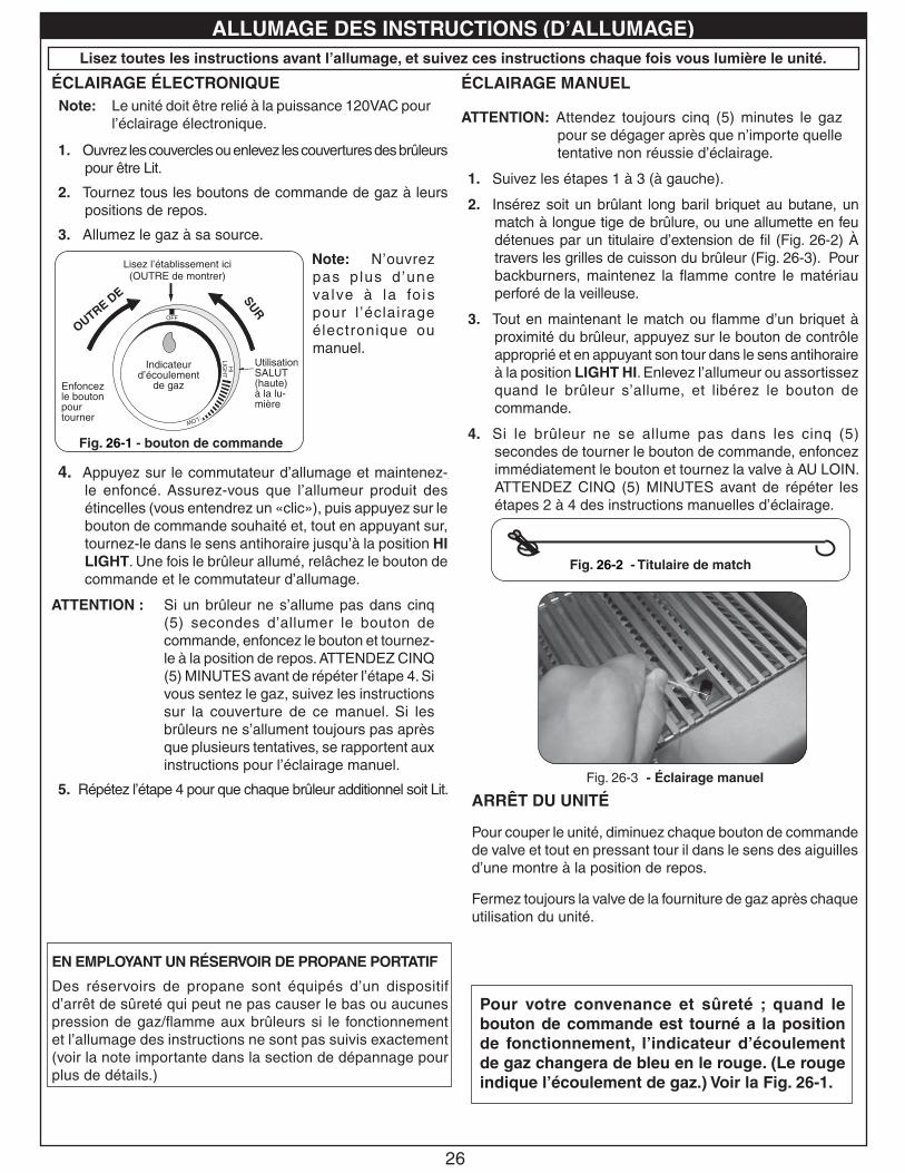
Fig. 26-1 - bouton de commande
OFF
TOTURN O
FF
TOTURN ON
Read settinghere
HIGH to LIGHTH
ILIG
HT
LOW
Lisez l’établissement ici (OUTRE de montrer)
OUTRE DE SUR
Utilisation SALUT (haute) à la lu-mière
Enfoncez le bouton pour tourner
Indicateur d’écoulement
de gaz
Pour votre convenance et sûreté ; quand le bouton de commande est tourné a la position de fonctionnement, l’indicateur d’écoulement de gaz changera de bleu en le rouge. (Le rouge indique l’écoulement de gaz.) Voir la Fig. 26-1.
Note: Le unité doit être relié à la puissance 120VAC pour l’éclairage électronique.
2. Insérez soit un brûlant long baril briquet au butane, un match à longue tige de brûlure, ou une allumette en feu détenues par un titulaire d’extension de fil (Fig. 26-2) À travers les grilles de cuisson du brûleur (Fig. 26-3). Pour backburners, maintenez la flamme contre le matériau perforé de la veilleuse.
3. Tout en maintenant le match ou flamme d’un briquet à proximité du brûleur, appuyez sur le bouton de contrôle approprié et en appuyant son tour dans le sens antihoraire à la position LIGHT HI. Enlevez l’allumeur ou assortissez quand le brûleur s’allume, et libérez le bouton de commande.
4. Si le brûleur ne se allume pas dans les cinq (5) secondes de tourner le bouton de commande, enfoncez immédiatement le bouton et tournez la valve à AU LOIN. ATTENDEZ CINQ (5) MINUTES avant de répéter les étapes 2 à 4 des instructions manuelles d’éclairage.
Fig. 26-3 - Éclairage manuel
Fig. 26-2 - Titulaire de match
4. Appuyez sur le commutateur d’allumage et maintenez-le enfoncé. Assurez-vous que l’allumeur produit des étincelles (vous entendrez un «clic»), puis appuyez sur le bouton de commande souhaité et, tout en appuyant sur, tournez-le dans le sens antihoraire jusqu’à la position HI LIGHT. Une fois le brûleur allumé, relâchez le bouton de commande et le commutateur d’allumage.
ATTENTION : Si un brûleur ne s’allume pas dans cinq (5) secondes d’allumer le bouton de commande, enfoncez le bouton et tournez-le à la position de repos. ATTENDEZ CINQ (5) MINUTES avant de répéter l’étape 4. Si vous sentez le gaz, suivez les instructions sur la couverture de ce manuel. Si les brûleurs ne s’allument toujours pas après que plusieurs tentatives, se rapportent aux instructions pour l’éclairage manuel.
5. Répétez l’étape 4 pour que chaque brûleur additionnel soit Lit.
ALLUMAGE DES INSTRUCTIONS (D’ALLUMAGE)
27
SHUTTING OFF THE UNIT
To shut off the unit, depress each valve control knob and while pressing turn it clockwise to the OFF position.
Always close the valve from the gas supply after each use of the unit.
ELECTRONIC LIGHTING
Note: Electronic lighting requires an installed 9-volt battery with a good charge.
1. Open lid(s) or remove cover(s) from burner(s) to be lit.
2. Turn all gas control knob(s) to their OFF position(s).
3. Turn on the gas at its source.
Note: DO NOT turn on more than one valve at a time for either e l ec t ron i c o r manual lighting.
4. Depress the desired control knob for 5 seconds. Ensure the igniter is glowing (inside of lighting tube), then, while pressing turn the knob counterclockwise to the HI LIGHT position. Once the burner lights, release the knob.
CAUTION: If a burner does not light within five (5) seconds of turning on the control knob, depress the knob and turn it to the OFF position. WAIT FIVE (5) MINUTES before repeating step 4. If you smell gas, follow the instructions on the cover of this manual. If the burners still do not light after several attempts, refer to the instructions for manual lighting.
5. Repeat step 4 for each additional burner to be lit.
Read all instructions before lighting, and follow these instructions each time you light the unit.
Fig. 27-2 - Manual lighting
Lighting tube
Lighter
WHEN USING A PORTABLE PROPANE TANKPropane tanks are equipped with a safety shutdown device that may cause low or no gas pressure/flame at the burners if operating and lighting instructions are not followed exactly (See important note in the TROUBLESHOOTING section for more details.)
MANUAL LIGHTING
CAUTION: Always wait five (5) minutes for gas to clear after any unsuccessful lighting attempt.
1. Follow steps 1 through 3 (left).
2. Insert either a burning long-barrel butane lighter or a burning long-stem match through the cooking grid opening to the top of the lighting tube (Fig. 27-2). For backburners, hold the flame against the surface of the backburner.
For sideburners, hold the flame against the burner.
3. Hold the match / lighter flame at the top of the lighting tube for 5 seconds, or, next to the sideburner / backburner. Then depress the appropriate control knob and while pressing turn it counterclockwise to the HI LIGHT position. Remove the lighter or match when the burner lights, and release the control knob.
4. If the burner does not light within five (5) seconds of turning the control knob, immediately depress the knob and turn the valve to OFF. WAIT FIVE (5) MINUTES before repeating steps 2 through 4 of the MANUAL LIGHTING instructions.
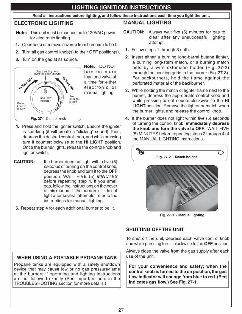
Fig. 27-1 Control knob
OFF
TOTURN O
FF
TOTURN ON
Read settinghere
HIGH to LIGHTH
ILIG
HT
LOW
Read setting here (OFF position shown)
To Tu
rn O
FF
To Turn ON
Use HI (high) to lightPress
knob in to turn
Gas Flow Indicator
For your convenience and safety; when the control knob is turned to the on position, the gas flow indicator will change from blue to red. (Red indicates gas flow.) See Fig. 27-1.
ELECTRONIC LIGHTING
Note: This unit must be connected to 120VAC power for electronic lighting.
2. Insert either a burning long-barrel butane lighter, a burning long-stem match, or a burning match held by a wire extension holder (Fig. 27-2) through the cooking grids to the burner (Fig. 27-3). For backburners, hold the flame against the perforated material of the backburner.
3. While holding the match or lighter flame next to the burner, depress the appropriate control knob and while pressing turn it counterclockwise to the HI LIGHT position. Remove the lighter or match when the burner lights, and release the control knob.
4. If the burner does not light within five (5) seconds of turning the control knob, immediately depress the knob and turn the valve to OFF. WAIT FIVE (5) MINUTES before repeating steps 2 through 4 of the MANUAL LIGHTING instructions.
Fig. 27-2 - Match holder
SHUTTING OFF THE UNIT
To shut off the unit, depress each valve control knob and while pressing turn it clockwise to the OFF position.
Always close the valve from the gas supply after each use of the unit.
Fig. 27-3 - Manual lighting
4. Press and hold the igniter switch. Ensure the igniter is sparking (it will create a “clicking” sound), then, depress the desired control knob, and while pressing turn it counterclockwise to the HI LIGHT position. Once the burner lights, release the control knob and igniter switch.
CAUTION: If a burner does not light within five (5) seconds of turning on the control knob, depress the knob and turn it to the OFF position. WAIT FIVE (5) MINUTES before repeating step 4. If you smell gas, follow the instructions on the cover of this manual. If the burners still do not light after several attempts, refer to the instructions for manual lighting.
5. Repeat step 4 for each additional burner to be lit.
LIGHTING (IGNITION) INSTRUCTIONS
28
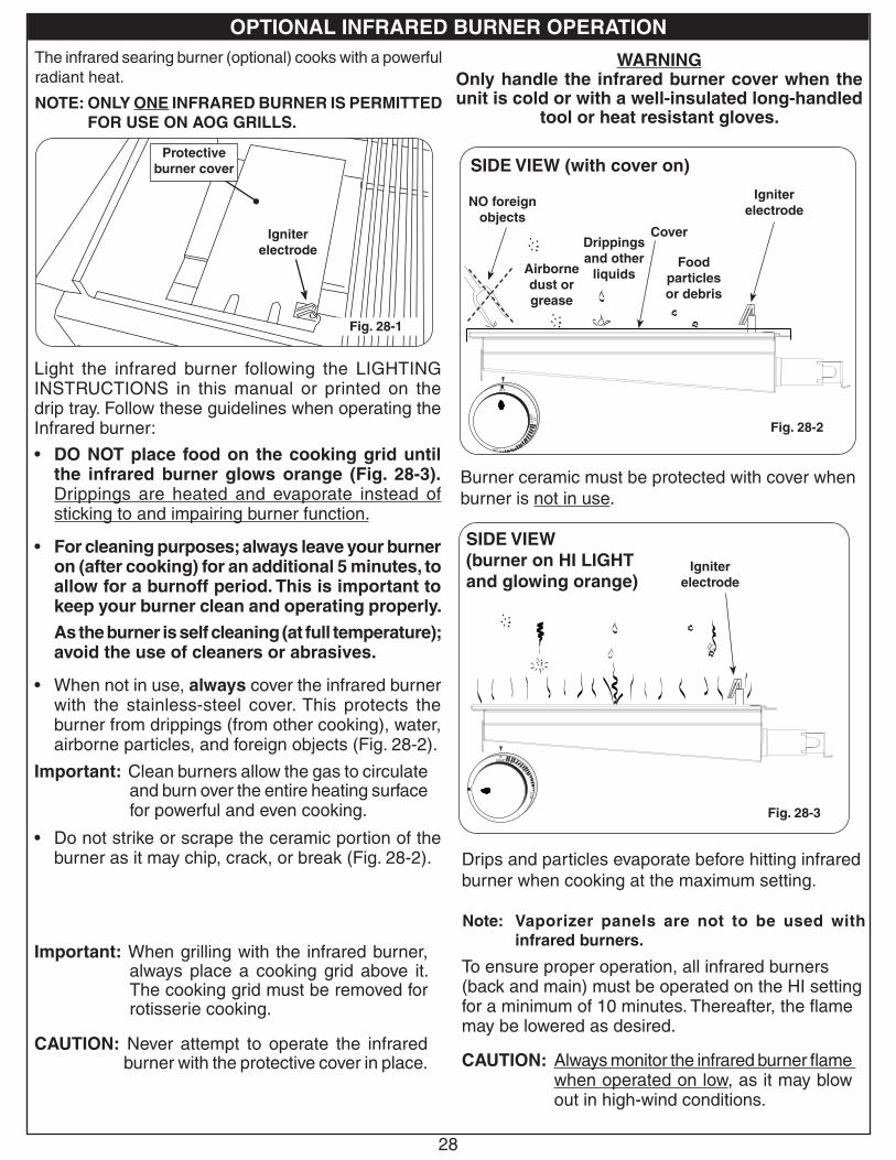
The infrared searing burner (optional) cooks with a powerful radiant heat.
Light the infrared burner following the LIGHTING INSTRUCTIONS in this manual or printed on the drip tray. Follow these guidelines when operating the Infrared burner:
• DO NOT place food on the cooking grid until the infrared burner glows orange (Fig. 28-3). Drippings are heated and evaporate instead of sticking to and impairing burner function.
• For cleaning purposes; always leave your burner on (after cooking) for an additional 5 minutes, to allow for a burnoff period. This is important to keep your burner clean and operating properly.
As the burner is self cleaning (at full temperature); avoid the use of cleaners or abrasives.
• When not in use, always cover the infrared burner with the stainless-steel cover. This protects the burner from drippings (from other cooking), water, airborne particles, and foreign objects (Fig. 28-2).
Important: Clean burners allow the gas to circulate and burn over the entire heating surface for powerful and even cooking.
• Do not strike or scrape the ceramic portion of the burner as it may chip, crack, or break (Fig. 28-2).
Note: Digital thermometer does not give accurate readings for infrared burners.
Important: When grilling with the infrared burner, always place a cooking grid above it. The cooking grid must be removed for rotisserie cooking.
CAUTION: Never attempt to operate the infrared burner with the protective cover in place.
WARNINGOnly handle the infrared burner cover when the unit is cold or with a well-insulated long-handled
tool or heat resistant gloves.
Burner ceramic must be protected with cover when burner is not in use.
Drips and particles evaporate before hitting infrared burner when cooking at the maximum setting.
Note: Flavor grids are not to be used with infrared burners.
To ensure proper operation, all infrared burners (back and main) must be operated on the HI setting for a minimum of 10 minutes. Thereafter, the flame may be lowered as desired.
CAUTION: Always monitor the infrared burner flame when operated on low, as it may blow out in high-wind conditions.
OF
F
HILIGHT
LOW
Fig. 28-3
SIDE VIEW (burner on HI LIGHT and glowing orange)
Igniter electrode
OFF
HI
LIGH
T
LOW
Fig. 28-2
Cover
SIDE VIEW (with cover on)
Igniter electrode
Food particles or debris
Drippings and other
liquidsAirborne dust or grease
NO foreign objects
Fig. 28-1
Igniter electrode
Note: Vaporizer panels are not to be used with infrared burners.
The infrared searing burner (optional) cooks with a powerful radiant heat.
NOTE: ONLY ONE INFRARED BURNER IS PERMITTED FOR USE ON AOG GRILLS.
Protective burner cover
OPTIONAL INFRARED BURNER OPERATION
29
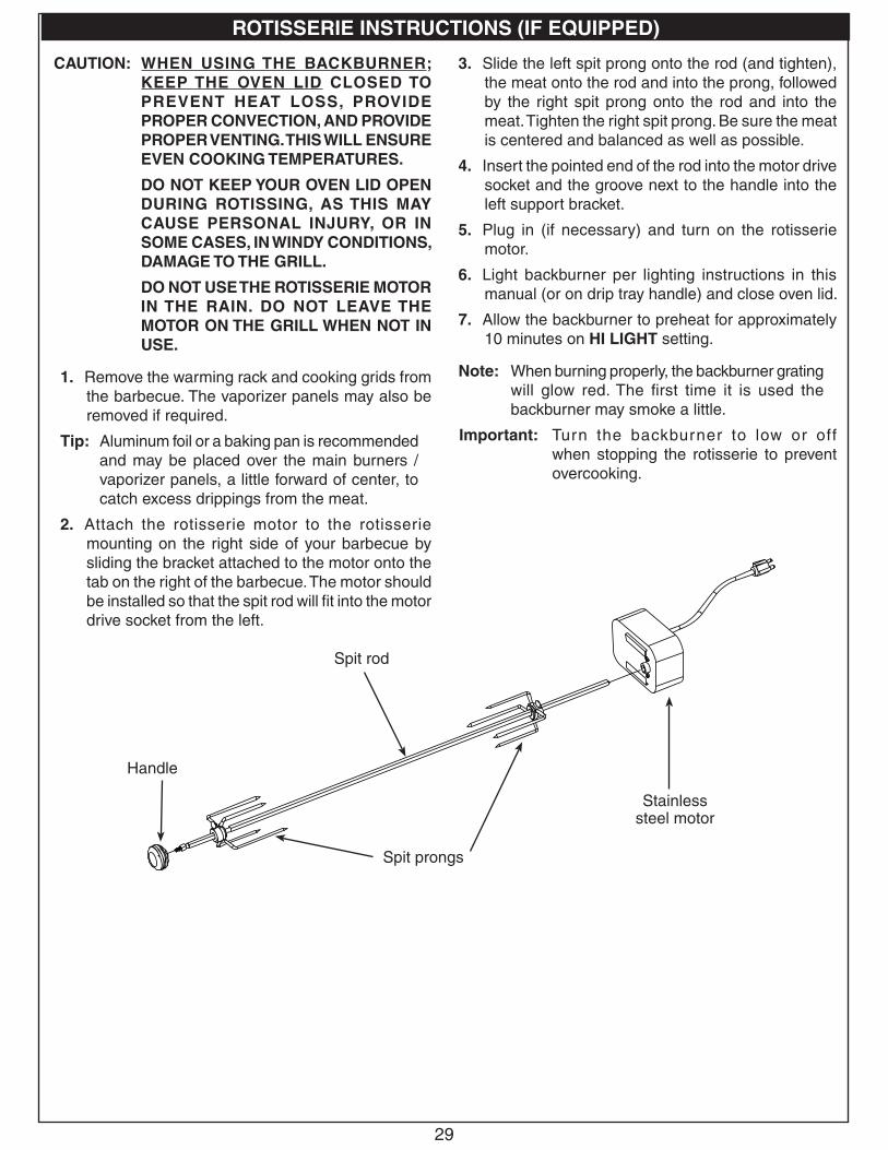
ROTISSERIE INSTRUCTIONS (IF EQUIPPED)
Spit rod
Handle
Spit prongs
Stainless steel motor
CAUTION: WHEN USING THE BACKBURNER; KEEP THE OVEN LID CLOSED TO PREVENT HEAT LOSS, PROVIDE PROPER CONVECTION, AND PROVIDE PROPER VENTING. THIS WILL ENSURE EVEN COOKING TEMPERATURES.
DO NOT KEEP YOUR OVEN LID OPEN DURING ROTISSING, AS THIS MAY CAUSE PERSONAL INJURY, OR IN SOME CASES, IN WINDY CONDITIONS, DAMAGE TO THE GRILL.
DO NOT USE THE ROTISSERIE MOTOR IN THE RAIN. DO NOT LEAVE THE MOTOR ON THE GRILL WHEN NOT IN USE.
1. Remove the warming rack and cooking grids from the barbecue. The vaporizer panels may also be removed if required.
Tip: Aluminum foil or a baking pan is recommended and may be placed over the main burners / vaporizer panels, a little forward of center, to catch excess drippings from the meat.
2. Attach the rotisserie motor to the rotisserie mounting on the right side of your barbecue by sliding the bracket attached to the motor onto the tab on the right of the barbecue. The motor should be installed so that the spit rod will fit into the motor drive socket from the left.
3. Slide the left spit prong onto the rod (and tighten), the meat onto the rod and into the prong, followed by the right spit prong onto the rod and into the meat. Tighten the right spit prong. Be sure the meat is centered and balanced as well as possible.
4. Insert the pointed end of the rod into the motor drive socket and the groove next to the handle into the left support bracket.
5. Plug in (if necessary) and turn on the rotisserie motor.
6. Light backburner per lighting instructions in this manual (or on drip tray handle) and close oven lid.
7. Allow the backburner to preheat for approximately 10 minutes on HI LIGHT setting.
Note: When burning properly, the backburner grating will glow red. The first time it is used the backburner may smoke a little.
Important: Turn the backburner to low or off when stopping the rotisserie to prevent overcooking.
30
Your grill requires regular cleaning and maintenance. Refer to these instructions for details. Performing these procedures will ensure proper operation, appearance, and safety.
WARNINGS
• Prior to servicing or cleaning make sure the unit is completely cool, the control knobs are turned to the OFF position, the gas supply is shut off, the light switch is off, and the power supply is disconnected (as applicable and unless otherwise stated).
• Wear appropriate gloves and safety glasses during any servicing or cleaning.
• DO NOT spray any cleaner or liquids on the grill when hot.
• The grill MUST be cleaned regularly to prevent grease build-up and other food deposits. A clean and well maintained grill prevents the risk of grease build-up and grease fires.
• Verify proper operation after servicing or deep cleaning.
• See INSTALLATION, OPERATION, AND SAFETY INFORMATION section for additional related information.
CLEANING YOUR GRILL
Before Each Use1. Inspect and clean the exterior surfaces of the unit: With a cool grill, clean any dust, grease, splatter, or spills as
needed with a damp clean cloth.
After Each Use1. Perform a burn-off and clean the cooking grids: Operate the grill on high with the hood closed for 15 minutes to
burn-off food and grease and allow for an easier cooking grid clean. Then turn OFF the grill and use a grill brush to clean the cooking grids of all residue. Use long-handled insulated BBQ tools and wear an insulated glove / oven mitt.
2. Check and clean your drip tray: When the grill is cool, carefully remove the drip tray and dispose of contents appropriately. Clean tray in a soapy water solution if needed. For tough deposits, a copper pad can be used. Rinse and dry completely.
3. Cover your grill: Once the grill is dry and cool, cover your grill with an AOG protective cover (not included).
Twice A Year (or as needed) - Deep Clean1. Interior of grill: In addition to cleaning the cooking grids and drip tray, a deep clean of the interior of
the grill, burners, and all components MUST be performed twice year (or as needed depending on use). Refer to the CARE, CLEANING, & MAINTENANCE GUIDE manual provided with your grill, or simply scan the QR code on the right.
Important: The burner ports and carry-over ports/slots MUST be kept clean to ensure proper ignition and operation. The guide provides all details on cleaning.
2. Exterior of grill: With a cool grill, use a grill cleaner (or a soapy water solution) and a clean cloth to remove grease and dirt from the outside of the grill. For tough deposits, a copper pad can be used. Always wipe with the grain. Rinse and dry completely. Then follow up with a stainless steel cleaner and a clean cloth. DO NOT use other cleaners or chemicals.
If this routine cleaning is not performed, the stainless steel may become dull and develop surface rust (due to use and atmospheric conditions). If left uncleaned, significant damage and pitting may occur.
Important: DO NOT use steel wool, any other metal tools, or any other cleaners/chemicals to clean the exterior other than recommended above. Such items promote rust.
Note: Due to the nature of stainless steel, temperatures produced by the grilling process will cause discoloration. This can be reduced by routine cleaning.
Wipe with grain
Fig. 30-1 Wipe with grain
SERVICING AND CLEANING
31
For Environments High In Salt, Chloride, Or Other Corrosive ChemicalsWhen this grill is installed in a corrosive environment such as near the ocean (salt air), poolside (chlorine and/or pool chemicals) or any other location with exposure to high salt/chloride content or corrosive chemicals/solutions, it will be more susceptible to corrosion and MUST be maintained/cleaned more frequently.
• DO NOT store any corrosive chemicals (chlorine, hydrochloric acid, fertilizer, etc.) near your stainless steel grill.
• DO NOT allow any corrosive materials (masonry dust, debris, etc.) to settle on your stainless steel grill.
• These environments, chemicals, and materials may cause the 304 stainless steel to develop surface rust and consequently pitting. Under these conditions the grill exterior MUST be cleaned at least monthly. Inspect your grill often and clean accordingly.
Protecting Your GrillAn optional AOG protective cover will protect your grill when not in use. Install the cover on a cool and dry grill. DO NOT cover a damp grill. During high humidity or after rainy conditions, remove the cover to dry trapped moisture if present. (If the cover is installed over a damp grill it can cause surface rust.)
Ensure that the INSIDE of the cover is DRY before putting it back on the grill.
SERVICING AND CLEANING (cont.)
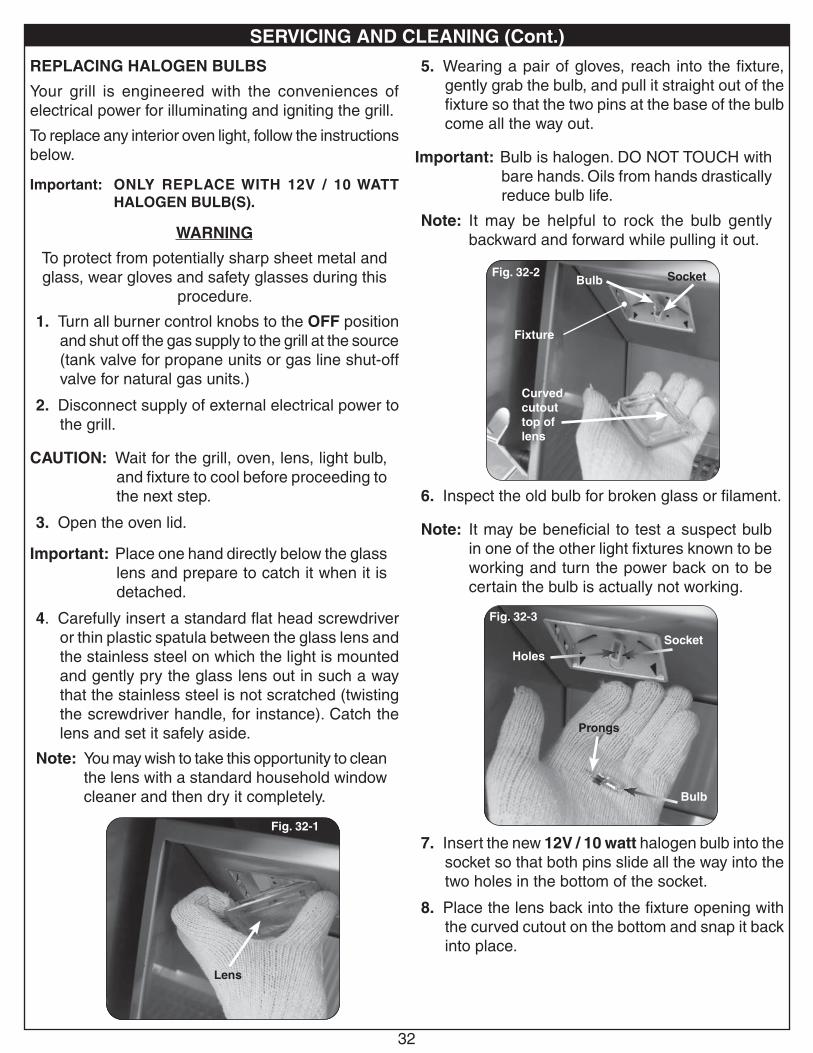
32
REPLACING HALOGEN BULBS
Your grill is engineered with the conveniences of electrical power for illuminating and igniting the grill.
To replace any interior oven light, follow the instructions below.
Important: ONLY REPLACE WITH 12V / 10 WATT HALOGEN BULB(S).
WARNING
To protect from potentially sharp sheet metal and glass, wear gloves and safety glasses during this
procedure.
1. Turn all burner control knobs to the OFF position and shut off the gas supply to the grill at the source (tank valve for propane units or gas line shut-off valve for natural gas units.)
2. Disconnect supply of external electrical power to the grill.
CAUTION: Wait for the grill, oven, lens, light bulb, and fixture to cool before proceeding to the next step.
3. Open the oven lid.
Important: Place one hand directly below the glass lens and prepare to catch it when it is detached.
4. Carefully insert a standard flat head screwdriver or thin plastic spatula between the glass lens and the stainless steel on which the light is mounted and gently pry the glass lens out in such a way that the stainless steel is not scratched (twisting the screwdriver handle, for instance). Catch the lens and set it safely aside.
Note: You may wish to take this opportunity to clean the lens with a standard household window cleaner and then dry it completely.
5. Wearing a pair of gloves, reach into the fixture, gently grab the bulb, and pull it straight out of the fixture so that the two pins at the base of the bulb come all the way out.
Important: Bulb is halogen. DO NOT TOUCH with bare hands. Oils from hands drastically reduce bulb life.
Note: It may be helpful to rock the bulb gently backward and forward while pulling it out.
6. Inspect the old bulb for broken glass or filament.
Note: It may be beneficial to test a suspect bulb in one of the other light fixtures known to be working and turn the power back on to be certain the bulb is actually not working.
7. Insert the new 12V / 10 watt halogen bulb into the socket so that both pins slide all the way into the two holes in the bottom of the socket.
8. Place the lens back into the fixture opening with the curved cutout on the bottom and snap it back into place.
Fig. 32-1
Lens
Fig. 32-3
Bulb
Prongs
SocketHoles
Fig. 32-2
Fixture
Socket
Curved cutout top of lens
Bulb
SERVICING AND CLEANING (Cont.)
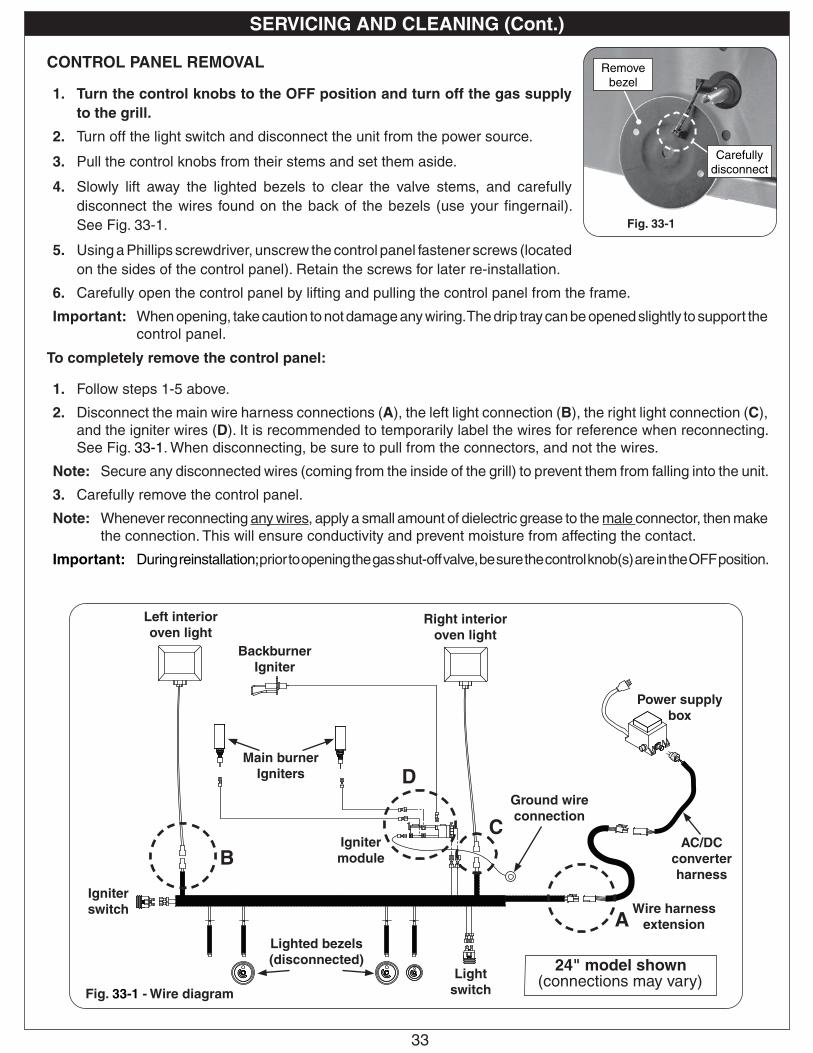
33
Fig. 33-1 - Wire diagram
A
B
D
24" model shown (connections may vary)
Power supply box
Wire harness extension
Left interior oven light
Main burner Igniters
Backburner Igniter
Igniter module
Igniter switch
Light switch
CONTROL PANEL REMOVAL
1. Turn the control knobs to the OFF position and turn off the gas supply to the grill.
2. Turn off the light switch and disconnect the unit from the power source.
3. Pull the control knobs from their stems and set them aside.
4. Slowly lift away the lighted bezels to clear the valve stems, and carefully disconnect the wires found on the back of the bezels (use your fingernail). See Fig. 33-1.
5. Using a Phillips screwdriver, unscrew the control panel fastener screws (located on the sides of the control panel). Retain the screws for later re-installation.
6. Carefully open the control panel by lifting and pulling the control panel from the frame.
Important: When opening, take caution to not damage any wiring. The drip tray can be opened slightly to support the control panel.
To completely remove the control panel:
1. Follow steps 1-5 above.
2. Disconnect the main wire harness connections (A), the left light connection (B), the right light connection (C), and the igniter wires (D). It is recommended to temporarily label the wires for reference when reconnecting. See Fig. 33-1. When disconnecting, be sure to pull from the connectors, and not the wires.
Note: Secure any disconnected wires (coming from the inside of the grill) to prevent them from falling into the unit.
3. Carefully remove the control panel.
Note: Whenever reconnecting any wires, apply a small amount of dielectric grease to the male connector, then make the connection. This will ensure conductivity and prevent moisture from affecting the contact.
Important: During reinstallation; prior to opening the gas shut-off valve, be sure the control knob(s) are in the OFF position.
Fig. 33-1
Remove bezel
Lighted bezels(disconnected)
C
Right interior oven light
AC/DC converter harness
Ground wire connection
Carefully disconnect
SERVICING AND CLEANING (Cont.)
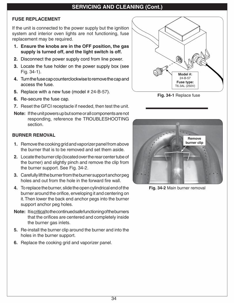
34
FUSE REPLACEMENT
If the unit is connected to the power supply but the ignition system and interior oven lights are not functioning, fuse replacement may be required.
1. Ensure the knobs are in the OFF position, the gas supply is turned off, and the light switch is off.
2. Disconnect the power supply cord from line power.
3. Locate the fuse holder on the power supply box (see Fig. 34-1).
4. Turn the fuse cap counterclockwise to remove the cap and access the fuse.
5. Replace with a new fuse (model # 24-B-57).
6. Re-secure the fuse cap.
7. Reset the GFCI receptacle if needed, then test the unit.
Note: If the unit powers up but some or all components are not responding, reference the TROUBLESHOOTING section.
BURNER REMOVAL
1. Remove the cooking grid and vaporizer panel from above the burner that is to be removed and set them aside.
2. Locate the burner clip (located over the rear center tube of the burner) and slightly pinch and remove the clip from the burner support. See Fig. 34-2.
3. Carefully lift the burner from the burner support anchor peg holes and out from the hole in the forward fire wall.
4. To replace the burner, slide the open cylindrical end of the burner around the orifice, enveloping it and centering on it. Then lower the back end anchor pegs into the burner support anchor peg holes.
Note: It is critical to the continued safe functioning of the burners that the orifices are centered and completely inside the burner gas inlets.
5. Re-install the burner clip around the burner and into the holes in the burner support.
6. Replace the cooking grid and vaporizer panel.
Fig. 34-1 Replace fuse
Model #: 24-B-57
Fuse type: T6.3AL (250V)
Fig. 34-2 Main burner removal
Remove burner clip
SERVICING AND CLEANING (Cont.)
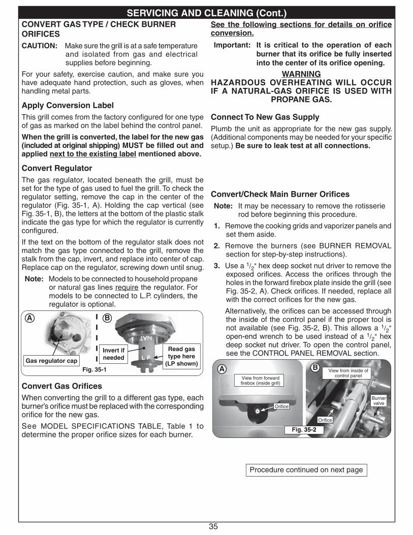
35
SERVICING AND CLEANING (Cont.)
Convert/Check Main Burner OrificesNote: It may be necessary to remove the rotisserie
rod before beginning this procedure.
1. Remove the cooking grids and vaporizer panels and set them aside.
2. Remove the burners (see BURNER REMOVAL section for step-by-step instructions).
3. Use a 1/2" hex deep socket nut driver to remove the exposed orifices. Access the orifices through the holes in the forward firebox plate inside the grill (see Fig. 35-2, A). Check orifices. If needed, replace all with the correct orifices for the new gas.
Alternatively, the orifices can be accessed through the inside of the control panel if the proper tool is not available (see Fig. 35-2, B). This allows a 1/2" open-end wrench to be used instead of a 1/2" hex deep socket nut driver. To open the control panel, see the CONTROL PANEL REMOVAL section.
Procedure continued on next page
A B
Orifice
View from forward firebox (inside grill)
Orifice
View from inside of control panel
Fig. 35-2
Burner valve
CONVERT GAS TYPE / CHECK BURNER ORIFICESCAUTION: Make sure the grill is at a safe temperature
and isolated from gas and electrical supplies before beginning.
For your safety, exercise caution, and make sure you have adequate hand protection, such as gloves, when handling metal parts.
Apply Conversion LabelThis grill comes from the factory configured for one type of gas as marked on the label behind the control panel.
When the grill is converted, the label for the new gas (included at original shipping) MUST be filled out and applied next to the existing label mentioned above.
Convert RegulatorThe gas regulator, located beneath the grill, must be set for the type of gas used to fuel the grill. To check the regulator setting, remove the cap in the center of the regulator (Fig. 35-1, A). Holding the cap vertical (see Fig. 35-1, B), the letters at the bottom of the plastic stalk indicate the gas type for which the regulator is currently configured.
If the text on the bottom of the regulator stalk does not match the gas type connected to the grill, remove the stalk from the cap, invert, and replace into center of cap. Replace cap on the regulator, screwing down until snug.
Note: Models to be connected to household propane or natural gas lines require the regulator. For models to be connected to L.P. cylinders, the regulator is optional.
Convert Gas OrificesWhen converting the grill to a different gas type, each burner’s orifice must be replaced with the corresponding orifice for the new gas.
See MODEL SPECIFICATIONS TABLE, Table 1 to determine the proper orifice sizes for each burner.
See the following sections for details on orifice conversion.
Important: It is critical to the operation of each burner that its orifice be fully inserted into the center of its orifice opening.
WARNINGHAZARDOUS OVERHEATING WILL OCCUR IF A NATURAL-GAS ORIFICE IS USED WITH
PROPANE GAS.
Connect To New Gas SupplyPlumb the unit as appropriate for the new gas supply. (Additional components may be needed for your specific setup.) Be sure to leak test at all connections.
Fig. 35-1
A B
Invert if needed
Read gas type here
(LP shown)Gas regulator cap
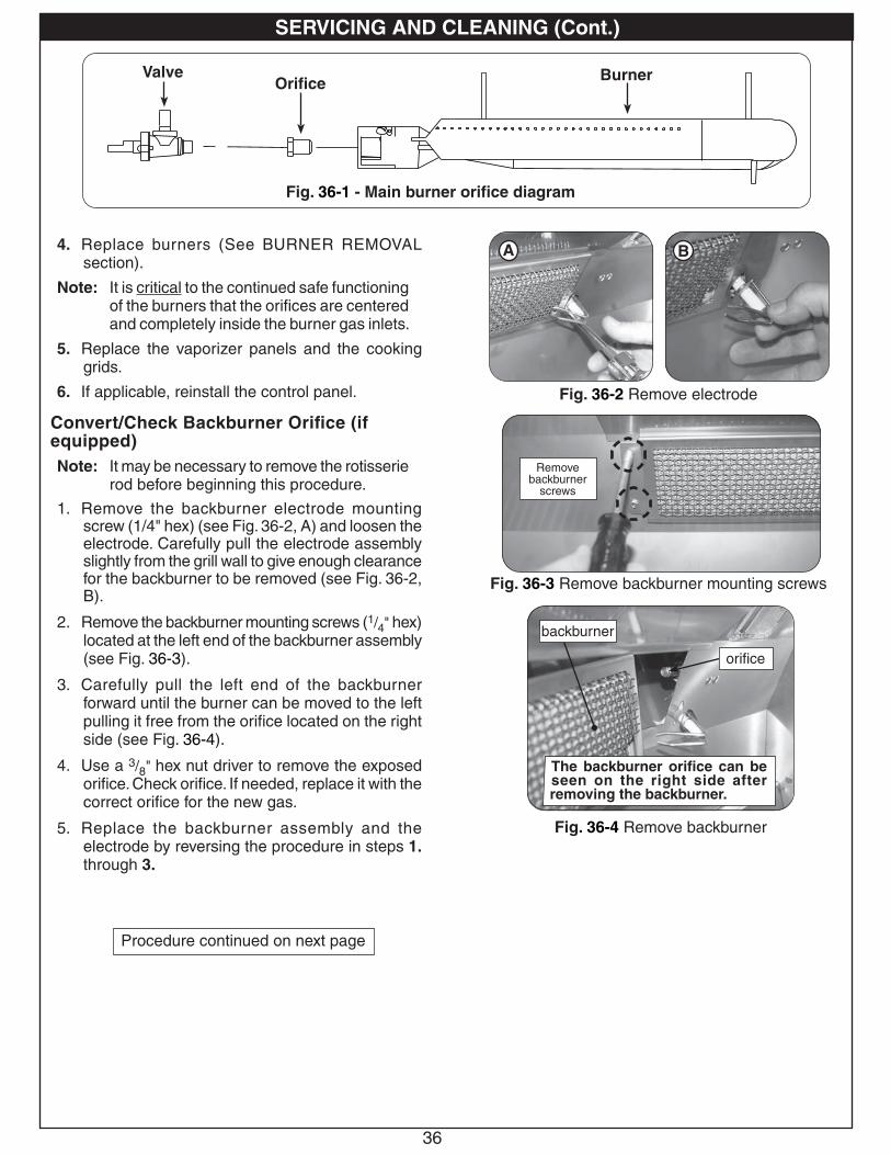
36
Fig. 36-3 Remove backburner mounting screws
Remove backburner
screws
Fig. 36-2 Remove electrode
Fig. 36-1 - Main burner orifice diagram
Orifice BurnerValve
4. Replace burners (See BURNER REMOVAL section).
Note: It is critical to the continued safe functioning of the burners that the orifices are centered and completely inside the burner gas inlets.
5. Replace the vaporizer panels and the cooking grids.
6. If applicable, reinstall the control panel.
Convert/Check Backburner Orifice (if equipped)Note: It may be necessary to remove the rotisserie
rod before beginning this procedure.
1. Remove the backburner electrode mounting screw (1/4" hex) (see Fig. 36-2, A) and loosen the electrode. Carefully pull the electrode assembly slightly from the grill wall to give enough clearance for the backburner to be removed (see Fig. 36-2, B).
2. Remove the backburner mounting screws (1/4" hex) located at the left end of the backburner assembly (see Fig. 36-3).
3. Carefully pull the left end of the backburner forward until the burner can be moved to the left pulling it free from the orifice located on the right side (see Fig. 36-4).
4. Use a 3/8" hex nut driver to remove the exposed orifice. Check orifice. If needed, replace it with the correct orifice for the new gas.
5. Replace the backburner assembly and the electrode by reversing the procedure in steps 1. through 3.
Fig. 36-4 Remove backburner
The backburner orifice can be seen on the right side after removing the backburner.
backburner
orifice
Procedure continued on next page
A B
SERVICING AND CLEANING (Cont.)
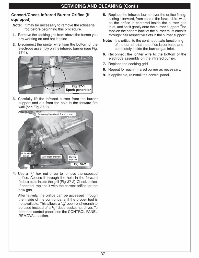
37
5. Replace the infrared burner over the orifice fitting, sliding it forward, from behind the forward fire wall, so the orifice is centered inside the burner gas inlet, and set it gently onto the burner support. The tabs on the bottom back of the burner must each fit through their respective slots in the burner support.
Note: It is critical to the continued safe functioning of the burner that the orifice is centered and completely inside the burner gas inlet.
6. Reconnect the igniter wire to the bottom of the electrode assembly on the infrared burner.
7. Replace the cooking grid.
8. Repeat for each infrared burner as necessary.
9. If applicable, reinstall the control panel.
Convert/Check Infrared Burner Orifice (if equipped)Note: It may be necessary to remove the rotisserie
rod before beginning this procedure.
1. Remove the cooking grid from above the burner you are working on and set it aside.
2. Disconnect the igniter wire from the bottom of the electrode assembly on the infrared burner (see Fig. 37-1).
3. Carefully lift the infrared burner from the burner support and out from the hole in the forward fire wall (see Fig. 37-2).
4. Use a 1/2" hex nut driver to remove the exposed orifice. Access it through the hole in the forward firebox plate inside the grill (Fig. 37-2). Check orifice. If needed, replace it with the correct orifice for the new gas.
Alternatively, the orifice can be accessed through the inside of the control panel if the proper tool is not available. This allows a 1/2" open-end wrench to be used instead of a 1/2" deep socket nut driver. To open the control panel, see the CONTROL PANEL REMOVAL section.
Removing / inserting infrared burner.
Fig. 37-2
Burner support
Hole with orifice Wire disconnected
Fig. 37-1Spark generator
SERVICING AND CLEANING (Cont.)
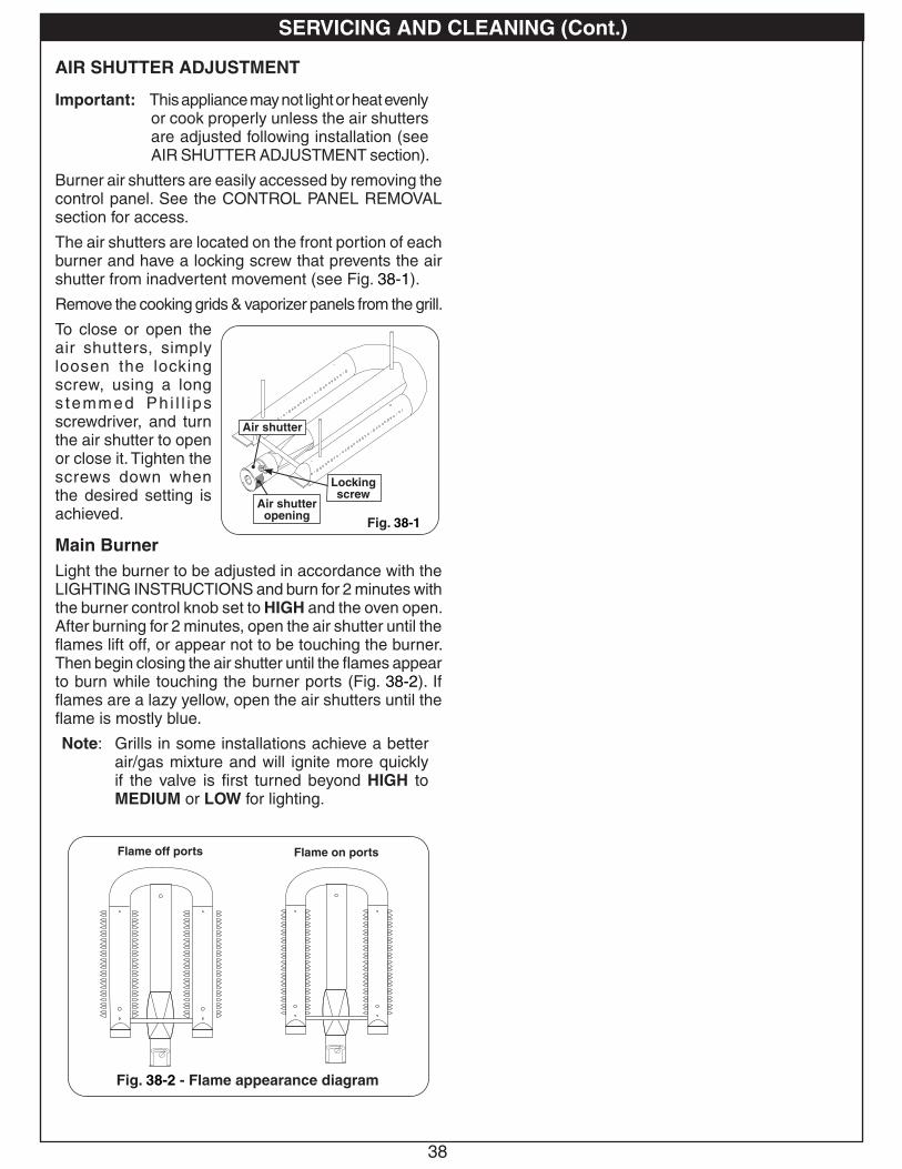
38
AIR SHUTTER ADJUSTMENT
Important: This appliance may not light or heat evenly or cook properly unless the air shutters are adjusted following installation (see AIR SHUTTER ADJUSTMENT section).
Burner air shutters are easily accessed by removing the control panel. See the CONTROL PANEL REMOVAL section for access.
The air shutters are located on the front portion of each burner and have a locking screw that prevents the air shutter from inadvertent movement (see Fig. 38-1).
Remove the cooking grids & vaporizer panels from the grill.
To close or open the air shutters, simply loosen the locking screw, using a long s temmed Ph i l l i ps screwdriver, and turn the air shutter to open or close it. Tighten the screws down when the desired setting is achieved.
Main BurnerLight the burner to be adjusted in accordance with the LIGHTING INSTRUCTIONS and burn for 2 minutes with the burner control knob set to HIGH and the oven open. After burning for 2 minutes, open the air shutter until the flames lift off, or appear not to be touching the burner. Then begin closing the air shutter until the flames appear to burn while touching the burner ports (Fig. 38-2). If flames are a lazy yellow, open the air shutters until the flame is mostly blue.
Note: Grills in some installations achieve a better air/gas mixture and will ignite more quickly if the valve is first turned beyond HIGH to MEDIUM or LOW for lighting.
Fig. 38-1
Locking screw
Air shutter
Fig. 38-2 - Flame appearance diagram
Flame off ports Flame on ports
SERVICING AND CLEANING (Cont.)
Air shutter opening
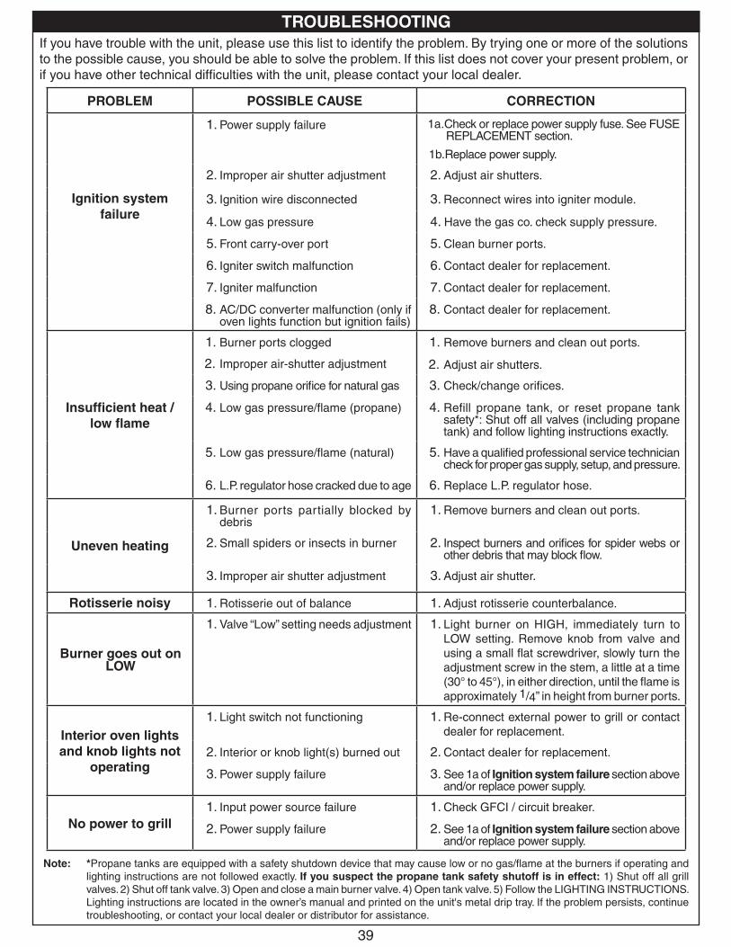
39
If you have trouble with the unit, please use this list to identify the problem. By trying one or more of the solutions to the possible cause, you should be able to solve the problem. If this list does not cover your present problem, or if you have other technical difficulties with the unit, please contact your local dealer.
PROBLEM POSSIBLE CAUSE CORRECTION
Ignition system failure
1. Power supply failure 1a.Check or replace power supply fuse. See FUSE REPLACEMENT section.
1b. Replace power supply.
2. Improper air shutter adjustment 2. Adjust air shutters.
3. Ignition wire disconnected 3. Reconnect wires into igniter module.
4. Low gas pressure 4. Have the gas co. check supply pressure.
5. Front carry-over port 5. Clean burner ports.
6. Igniter switch malfunction 6. Contact dealer for replacement.
7. Igniter malfunction 7. Contact dealer for replacement.
8. AC/DC converter malfunction (only if oven lights function but ignition fails)
8. Contact dealer for replacement.
Insufficient heat / low flame
1. Burner ports clogged
2. Improper air-shutter adjustment
1. Remove burners and clean out ports.
2. Adjust air shutters.
3. Using propane orifice for natural gas 3. Check/change orifices.
4. Low gas pressure/flame (propane) 4. Refill propane tank, or reset propane tank safety*: Shut off all valves (including propane tank) and follow lighting instructions exactly.
5. Low gas pressure/flame (natural) 5. Have a qualified professional service technician check for proper gas supply, setup, and pressure.
6. L.P. regulator hose cracked due to age 6. Replace L.P. regulator hose.
Uneven heating
1. Burner ports partially blocked by debris
1. Remove burners and clean out ports.
2. Small spiders or insects in burner 2. Inspect burners and orifices for spider webs or other debris that may block flow.
3. Improper air shutter adjustment 3. Adjust air shutter.
Rotisserie noisy 1. Rotisserie out of balance 1. Adjust rotisserie counterbalance.
Burner goes out on LOW
1. Valve “Low” setting needs adjustment 1. Light burner on HIGH, immediately turn to LOW setting. Remove knob from valve and using a small flat screwdriver, slowly turn the adjustment screw in the stem, a little at a time (30° to 45°), in either direction, until the flame is approximately 1/4” in height from burner ports.
Interior oven lights and knob lights not
operating
1. Light switch not functioning 1. Re-connect external power to grill or contact dealer for replacement.
2. Interior or knob light(s) burned out 2. Contact dealer for replacement.
3. Power supply failure 3. See 1a of Ignition system failure section above and/or replace power supply.
No power to grill 1. Input power source failure 1. Check GFCI / circuit breaker.
2. Power supply failure 2. See 1a of Ignition system failure section above and/or replace power supply.
Note: *Propane tanks are equipped with a safety shutdown device that may cause low or no gas/flame at the burners if operating and lighting instructions are not followed exactly. If you suspect the propane tank safety shutoff is in effect: 1) Shut off all grill valves. 2) Shut off tank valve. 3) Open and close a main burner valve. 4) Open tank valve. 5) Follow the LIGHTING INSTRUCTIONS. Lighting instructions are located in the owner’s manual and printed on the unit's metal drip tray. If the problem persists, continue troubleshooting, or contact your local dealer or distributor for assistance.
TROUBLESHOOTING
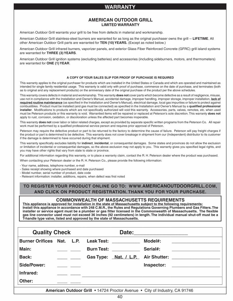
40Robert H. Peterson Co. • 14724 East Proctor Avenue • City of Industry, CA 91746
Quality Check Date:_________________Burner Orifices Nat. L.P. Leak Test: ___________ Model#: ___________________
Main: ____ ____ Burn Test: ___________ Serial#: ___________________
Back: ____ ____ Gas Type: Nat. / L.P. Air Shutter: ___________________
Side/Power: ____ ____ Inspector: ___________________
Infrared: ____ ____
Other: ____ ____
COMMONWEALTH OF MASSACHUSETTS REQUIREMENTSThis appliance is approved for installation in the state of Massachusetts subject to the following requirements:Install this appliance in accordance with 248 C.M.R., the Rules and Regulations Governing Plumbers and Gas Fitters. The installer or service agent must be a plumber or gas fitter licensed in the Commonwealth of Massachusetts. The flexible gas line connector used must not exceed 36 inches (92 centimeters) in length. The individual manual shut-off must be a T-handle type valve, listed and approved by the state of Massachusetts.
A COPY OF YOUR SALES SLIP FOR PROOF OF PURCHASE IS REQUIRED
This warranty applies to the original purchaser for products which are installed in the United States or Canada and which are operated and maintained as intended for single family residential usage. This warranty is valid only with proof of purchase, commence on the date of purchase, and terminates (both as to original and any replacement products) on the anniversary date of the original purchase of the product per the above schedules.
This warranty covers defects in material and workmanship. This warranty does not cover parts which become defective as a result of negligence, misuse, use not in compliance with the Installation and Owner’s Manual, accidental damage, improper handling, improper storage, improper installation, lack of required routine maintenance (as specified in the Installation and Owner’s Manual), electrical damage, local gas impurities or failure to protect against combustibles. Product must be installed (and gas must be connected) as specified in the Installation and Owner’s Manual by a qualified professional installer. Modifications to products which are not specifically authorized will void this warranty. Accessories, parts, valves, remotes, etc. when used must be Peterson products or this warranty is void. Warrantied items will be repaired or replaced at Peterson’s sole discretion. This warranty does not apply to rust, corrosion, oxidation, or discoloration unless the affected part becomes inoperable.
This warranty does not cover labor or labor related charges, except as provided by separate specific written programs from the Peterson Co. All repair work must be performed by a qualified professional service person and requires prior approval of Peterson.
Peterson may require the defective product or part to be returned to the factory to determine the cause of failure. Peterson will pay freight charges if the product or part is determined to be defective. This warranty does not cover breakage in shipment from our (Independent) distributor to its customer if the damage is determined to have occurred during that shipment.
This warranty specifically excludes liability for indirect, incidental, or consequential damages. Some states and provinces do not allow the exclusion or limitation of incidental or consequential damages, so the above exclusion may not apply to you. This warranty gives you specified legal rights, and you may have other rights that vary from state to state or province.
For additional information regarding this warranty, or to place a warranty claim, contact the R. H. Peterson dealer where the product was purchased.
When contacting your Peterson dealer or the R. H. Peterson Co., please provide the following information:
- Your name, address, telephone number, e-mail- Sales receipt showing where purchased and date purchased- Model number, serial number of product, date code- Relevant information: installer, additions, repairs, when defect was first noted
TO REGISTER YOUR PRODUCT ONLINE GO TO: WWW.RHPETERSON.COM,AND CLICK ON PRODUCT REGISTRATION. THANK YOU FOR YOUR PURCHASE.
American Outdoor Grill • 14724 Proctor Avenue • City of Industry, CA 91746
AMERICAN OUTDOOR GRILL LIMITED WARRANTY
American Outdoor Grill warrants your grill to be free from defects in material and workmanship.
American Outdoor Grill stainless-steel burners are warranted for as long as the original purchaser owns the grill -- LIFETIME. All other American Outdoor Grill parts are warranted for TEN (10) YEARS. (Except as noted below.)
American Outdoor Grill infrared burners, vaporizer panels, and exterior Glass Fiber Reinforced Concrete (GFRC) grill island systems are warranted for THREE (3) YEARS.
American Outdoor Grill ignition systems (excluding batteries) and accessories (including sideburners, motors, and thermometers) are warranted for ONE (1) YEAR.
TO REGISTER YOUR PRODUCT ONLINE GO TO: WWW.AMERICANOUTDOORGRILL.COM,AND CLICK ON PRODUCT REGISTRATION. THANK YOU FOR YOUR PURCHASE.
WARRANTY