Embed Size (px)
Citation preview

STUMP GRINDER MODELS 2550/2550T
OPERATING & PARTS MANUAL
BUILT WITH QUALITY AND DESIGN FIRST
ATTENTION:Depending on what replacement parts you are ordering, we will need the following information:
GRINDER COMPONENTSSerial Number
Model Number of Grinder
ENGINE COMPONENTSBrand
Engine Serial NumberEngine Model Number
Model No: _____________________
Serial No: _____________________
DEALER:
Name: _______________________
Address: ______________________
City/State: _____________________
Phone No: _____________________
Delivery Date: __________________
Engine Make: __________________
Serial No: _____________________
Clutch Make: __________________
Model: ___________ S/N ________
Copyright 10/14
MANUFACTURED BY BANDIT INDUSTRIES, INC.
6750 Millbrook RoadREMUS, MICHIGAN, USA 49340
PHONE: (800) 952-0178 IN USAPHONE: (989) 561-2270 OR 561-2272FAX: (989) 561-2273 ~ SALES DEPT.FAX: (989) 561-2962 ~ PARTS/SERVICEE-MAIL: www.banditchippers.com

Copyright 4-14 FORM #WV-124
I have inspected this equipment and find it in correct working condition. To the best of my knowledge, the customer and his/her personnel are aware of, and agree to the above procedures.Signed: ________________________________________________________ Date: ______________
(Dealer Representative)
The equipment has been thoroughly checked by the above named dealer representative, and I am satisfied with his/her instructions. I have also read, understand, and agree to reverse side of page. Signed: ________________________________________________________ Date: ______________
(Customer)
IT IS VERY IMPORTANT THAT THIS FORM IS FILLED OUT COMPLETELY & ACCURATELY. IF WE CANNOT READ THE PURCHASER’S INFORMATION OR IT IS INCORRECT, OUR CUSTOMER LIST WILL NOT BE ACCURATE.
IMPORTANT - THIS FORM MUST BE RETURNED TO THE CUSTOMER DATA DEPARTMENT WITHIN TEN (10) DAYS IN ORDER TO VALIDATE WARRANTY
Customer Data Department6750 Millbrook RoadRemus, MI, USA 49340Phone: (800) 952-0178 in USAPhone: (989) 561-2270Fax: (989) 561-2273E-mail: www.banditchippers.com
WARRANTY VALIDATION FORM (STUMP GRINDER)
1. ____ Customer has been instructed and understands operation and all safety aspects of operating the equipment. 2. ____ Customer has been instructed and understands that everyone within 100 feet (30 m) of machine must wear personal safety equipment (i.e. hard hat, face shield, safety glasses, gloves, ear protection, etc.) 3. ____ Customer has been instructed and understands equipment maintenance schedules, procedures, and that it is their responsibility to perform maintenance (i.e. retightening all fasteners as needed, clutch and belt adjustments, etc.) 4. ____ Customer has been advised and understands not to reach near the cutter head with hands or feet or to be locatednearthedebrisfieldwithenginerunning.Themachineoperatorsmustalways be located within easy reach of all control and shut down devices. 5. ____ Customer understands to not start grinding a stump without checking for power lines, water lines, sewer lines, phone lines, etc. 6. ____ Customer understands the purpose of and how to operate the shut down/shut off devices, and will not attempt to override any safety devices or guards. 7. ____ Customer has been instructed and understands to always remove the ignition key and completely disconnect battery from cables, wait for the cutter head to come to a complete stop, and to install the cutter head lock before performing any type of maintenance on the machine. Allow all the time necessary for the cutter head to come to a complete stop before opening the cutter head guard or starting any maintenance or service procedures. Customer has been shown and understands the purpose of the beltshield inspection holeandtonotattemptanymaintenanceuntilbeltsarevisuallyconfirmedtohavecometoacompletestop.8. ____ Customerhasbeeninstructedandunderstands:ToNot operate this machine without the factory approved cutterheadguardassemblyinplace.ToNot operate this machine with any type of make shift cutter head guard.ToNot operate this machine under any circumstances with the cutter guard open or unsecured. 9. ____ Customer has reviewed and understands limited warranty, and all written and visual instructions.10. ____ Customer has received, been advised, and understands the manuals, and the Safety/Service video supplied with the grinder.11. ____ All Danger, Warning and Operational decals are properly displayed on equipment and fully understood by customer.12. ____ Customer has been instructed, understands, and agrees that all potential operators must: See the supplied video, be instructed on all Danger, Warning, and Operational decals, read the manual and follow the procedures.
PURCHASER / OWNER INFORMATION:Company Name __________________________________ Contact Name _____________________ Mailing/Street Address _______________________________________ City _______________________ State __________________ Zip Code __________ Phone Number ( ___ ) __________________ E-mail ____________________________ Machine Model No. _________ Serial No. ______________ Date Put Into Service ______ Machine Hours _______ Engine Make __________________________ DEALER / SELLER INFORMATION:Dealer/Seller Name _______________________________ Contact Name _____________________ Mailing/Street Address _______________________________________ City _______________________ State __________________ Zip Code __________ Phone Number ( ___ ) __________________
Engine Serial No. ______________________

THIS IS GENERAL INFORMATION REVIEW, UNDERSTAND AND FOLLOW DETAILEDINFORMATION IN MANUALS AND DECALS AT ALL TIMES
START-UP PROCEDURESPosition the engage handle in the disengaged position and start the engine. Let the engine warm up at 1000 RPM’s. ( Follow engine manual information.)Themachinemayshowsigns of vibration until the engine can setatfullthrottle.Theenginecausesmost of this vibration until it is brought up to full throttle. Engage cutter wheel.
Once the engine is properly warmed up, bring the engine to full throttle. ( Follow engine break-in procedures.)
Make sure to wear all personal protection equipment and follow all safety standards per ANSI and OSHA instructions. Examples of equipment: hard hat, face shield, safety glasses, gloves, ear protection, etc.
Signal Word Likelihood of OccurrenceDegree of PotentialInjury or Damage
Will occur if warning is ignored
Can occur if warning is ignored
Will or can occur if warning is ignored
Important, but not hazard related
Severe
Minor
Minor to Severe
Severe
CAUTION!
NOTICE
DANGER!
WARNING!
SAFETY ALERT SYMBOLS AND NOTATIONSOPERATING INSTRUCTIONS BRUSH BANDIT STUMP GRINDERS
Torn or loose clothing ismore likely to getcaught in moving machinery parts or tree branches. Keep such items as long hair, shirt sleeves, and shirt tails properly contained. Avoid wearing necklaces, rings, watches, and especially neckties while operating this machinery. Make sure the machine is in excellent condition, and all the guards are in place, tight and secure. Wear all personal protection equipment and follow all safety standards per ANSI and OSHA instructions. Examples of equipment: hard hat, face shield, safety glasses, gloves, ear protection, etc. Do not wear gauntlet or secured fit gloves. Always keep a fully charged fire extinguisher with the machine while operating or servicing the machine.
Operators must at all times be located within easy reach of all feed control and shut-off deviceswhentheunitisrunning.Theymustbeattentive and prepared to activate the devices.
Thismachine isequippedwithsafetydecals,guards and designs for your protection. Don’t ever take the machine for granted, always be cautious and careful when operating your equipment. Read and follow all the instructions in your manual thoroughly. Your safety is dependent on your knowledge of how to operate and maintain this machine. You may obtain additional copies of this manual from your Bandit Dealer. Before operating machine, you must have all potential operators; read and understand manuals and decals, watch the video and follow the recommendations. Regardless of how hard a manufacturer tries to produce a safe machine, accidents still happen. Normally accidents are caused by people making mistakes.Theydonotreadthemanual,theyignorewarning decals or do not use lockouts provided for theirsafety.Thisnormallyhappensafterthepersonhas become accustomed to the machinery. In the initial start up and operation of the machinery, they are cautious, they are very careful because they do not understand the machine. Thisequipmentisintendedforusebypersonnelwho are experienced with similar equipment. Alwaysoperatesafely.Thereshouldbeatleasttwoqualifiedandtrainedoperatorsattheworksite.Theyshouldbepositionedinsafeworkinglocations,following safety procedures and instructions, andawareofeach otherswhereabouts. Thereshould, also, be at least two people on site during maintenance and service procedures in case an accident should occur. Never operate any machine whileundertheinfluenceofdrugsoralcohol. Keep children, bystanders and animals clear of working area. Never operate equipment that is in need of repair or adjustment.
DANGER!
Before starting the machine, take a minute tocheckafewthings.Thegrindershouldbein an area restricted from people passing by. Thisareaaroundthegrindermustbefreeofallobjects that can obstruct your movement when workingwiththegrinder.Themachineshouldbe checked for loose tools or foreign objects, especially in the grinding area. All tools not in use should be secured in a tool box.
WARNING!
DANGER!
DANGER!
Never go near cutter wheel or teeth while engine is running or cutter wheel is coasting to a stop.
Never grind materials that might contain wires, stones, nails, or other metal objects which may damage the teeth and become dangerous projectiles. Remove all rocks and stones from stump grinding area.
Donotgonearorin-linewiththedebrisfieldof the stump grinder while in operation. While grinding stumps, the chips and portions of the stumpflyfromthecutterwheelandcancausesevere injury.
Do Not start to grind a stump unless you are completely sure there are not any power lines, water lines, sewer lines, phone lines, etc. in the area above or below the ground level where you are grinding.
DANGER!
DANGER!
DANGER!
DANGER!
Before attempting any type of maintenance disengage clutch, turn off engine, wait for the cutter wheel to come to a complete stop, install the cutter wheel lock pin, disconnect battery, and make sure the ignition key is in your possession. ALWAYS install the lock pin into the cutter lock tube before working on the grinder. Simply slide the lock pin into the cutter wheel locktube.Thisistoensurethatthecutterwheelcannot be started while you are working on the grinder. If for some reason the cutter wheel would start to turn, it would simply hit the lock pin.
DANGER!
WARNING!
It is very important after you have operated a new machine for approximately an hour to shut down the machine and recheck all nuts and bolts. It is normal for nuts and bolts to loosen once on a new piece of machinery. If you tighten them now, there is a good possibility they won’t loosen again. Certain nuts and bolts should be checked periodically such as cutter teeth bolts, etc.fortorqueandfit. Most of the nuts used on the Bandit Grinder are self locking. After a nut or bolt has been removed five times, it should be replaced toensure proper tightness. This is especiallycritical on the cutter tooth bolts! After the engine is started, let the grinder wheel turn at the lowest RPM’s possible. Listen for any type of noise that is foreign. Any steel on steel noise is foreign. If you hear a noise, stoptheengine,findtheproblemandfixit.
Chip Curtain
Cutter Wheel
Cutter Wheel Engage Handle
Cutter WheelLock Pin
Cutter WheelGuard
Oil Cooler
Control Valves

All of the employees that build your equipment strive to manufacturer the very best quality product on the market. We would appreciate your efforts in letting us know how we are doing.
Wewouldlikeyoutooperateyourmachineforthirty(30)daysandthenfilloutthisquestionnaireandmailittous.Thiswillhelpustokeepproducingagoodproductandimprovingourproductsthroughyourrecommendations.
DATE PURCHASE: ______________________
MODEL: ________________________________
SERIAL NUMBER: _______________________
DEALER NAME: ________________________
_______________________________________
Copyright 7-04 FORM #Q-112
TO BE RETURNED AFTER THIRTY (30) DAYS OF OPERATION
Please return to: Customer Data Department 6750 Millbrook Road Remus, MI 49340
Phone: (800) 952-0178 in USA Phone: (989) 561-2270 Fax: (989) 561-2273 E-mail: www.banditchippers.com
STUMP GRINDER QUALITY REPORT
1. Did your machine perform to your expectations? _______________________________________
2. Was the machine delivered on schedule? _____________________________________________
3. Wasthepaintcolorandfinishtoyoursatisfaction?______________________________________
4. Was machine equipment as ordered? ________________________________________________
5. Did all welds appear to be high quality? ______________________________________________
6. Was the overall machine to your liking? ______________________________________________
7. What problems have you experienced? ______________________________________________
8. Have any components regularly loosened that caused problems? __________________________
9. Does the hydraulic system seem to have adequate power? ______________________________
10. Is the machine manufactured to accommodate service in an adequate manner? If not, please explain:
_______________________________________________________________________________
11. General comments and/or suggestions: ________________________________________________
_______________________________________________________________________________
_______________________________________________________________________________
12. Would you like to be contacted concerning more of our equipment? ________________________
YOUR COMPANY: ________________________________
NAME: __________________________________________
ADDRESS: ______________________________________
CITY: ___________________________________________
STATE & ZIP: _____________________________________
PHONE: ( ____ ) _________________________________
E-MAIL: _________________________________________


Bandit1Copyright 10/14
MODELS 2550/2550T TABLE OF CONTENTS
TABLE OF CONTENTS PAGE INTRODUCTION & WARRANTY .......................................................... 2 SERIAL NUMBER LOCATION ............................................................. 6 SAFETY PROCEDURES ...................................................................... 7 EQUIPMENT SPECIFICATIONS ........................................................... 11 DECALS ................................................................................................ 12 CONTROLS............................................................................................ 15 MACHINE OPERATION ........................................................................ 25 TRANSPORTATION PROCEDURES ................................................... 28 MAINTENANCE .................................................................................... 30 HYDRAULIC SECTION ................................................................. 41 CUTTER WHEEL SECTION .......................................................... 53 ELECTRICAL SECTION ................................................................ 56 LUBRICATION & COOLANT.......................................................... 68 REPLACEMENT PARTS SECTION ..................................................... 69 FRAME COMPONENTS ................................................................ 70 STEERING COMPONENTS .......................................................... 74 CUTTER WHEEL ARM COMPONENTS ....................................... 76 CUTTER WHEEL COMPONENTS ................................................ 78 TANK COMPONENTS ................................................................... 80 CONTROL BOX COMPONENTS .................................................. 81 SWING OUT COMPONENTS ........................................................ 82 REMOTE CONTROL COMPONENTS ........................................... 83 GRADING BLADE COMPONENTS .............................................. 84 HYDRAULIC COMPONENTS ........................................................ 85 SERVICE RECORD ............................................................................... 94
ANY PART, PORTION, DESIGN, NUMBER, SPECIFICATION, AND/OR DIMENSION IN THIS MANUAL IS SUBJECT TO CHANGE WITHOUT NOTICE BY THE MANUFACTURER.
NOTICE

Bandit2Copyright 10/14
INTRODUCTION & WARRANTY
INTRODUCTIONThepurposeof thismanual is toprovide theuserwithspecificationsandprocedures for theoperation, maintenanceandrepairof thisBANDITproduct. Aswithanypieceofequipment,safety should always be a constant thought while the machine is being operated, serviced or stored. In order to highlight this consideration, the material which addresses safety is proceeded by the following signal words:
Theequipment isdesignedandmanufactured inaccordancewith the latestproduct industrystandards. Thisalonedoesnotprevent injury. It is theoperator’sresponsibility tousegoodjudgement and follow the warnings and instructions as indicated in this manual, on the machine and follow all safety standards per ANSI and OSHA instructions.
Improper use of the product can result in severe personal injury. Personnel using the equipment mustbequalified,trainedandfamiliarwiththeoperatingproceduresasdefinedinthismanual,prior to operating the product.
It is the responsibility of the owner or employer to ensure that the operator is trained and prac-tices safe operation while using and servicing the machine. It is also the owner’s responsibility to provide and follow a regularly scheduled preventative maintenance and repair program on the product,usingonlyfactoryapprovedreplacementparts.Anyunapprovedrepairsormodificationsmay not only damage the machine and its performance, but could result in severe personal injury. Unapprovedrepairsormodificationswillvoidwarrantyandeliminatemanufacturerofanyliabilityclaims. Consult the equipment manufacturer!!!
Each machine is shipped with a manual, a customer’s check sheet on the product, and any available parts & service manuals on component parts not produced by this manufacturer. Additional copies of these manuals and check sheets can be purchased from the manufacturer, orthroughthedealer. Engineparts,serviceandmaintenancemanualsMUSTbepurchasedthrough the engine manufacturer or their dealer.
TheproducerofthisBanditproductreservestherighttomakeanymodificationsorrevisionstothedesignorspecificationsofitsmachinewithoutadvancenotice.Theproduceralsoreservesthe right to change machine and part prices as needed without advance notice.
Signal Word Likelihood of OccurrenceDegree of PotentialInjury or Damage
Will occur if warning is ignored
Can occur if warning is ignored
Will or can occur if warning is ignored
Important, but not hazard related
Severe
Minor
Minor to Severe
Severe
CAUTION!
NOTICE
NOTICE
WARNING!
WARNING!
DANGER!
WARNING!

Bandit3Copyright 10/14
BANDIT INDUSTRIES, INC.
EXPLANATION OF LIMITED WARRANTY
Thereareseveralformsthatmustbecompletelyfilledoutandreturnedtousinreferencetoourportion of warranty. Read and understand the Bandit Limited Warranty responsibilities. Some components on your machine are covered by their respective manufacturers and cannot be handled through Bandit Industries as stated in Warranty Section of this manual.
Use this manual to help you resolve what and where your problem is, in most cases you can fix iteasily. Ifyoustillhaveproblems,workthrough the dealer you purchased the machine through, or contact Bandit Industries direct if needed.
Make sure the following forms are used, for us as well as you, to keep track of service and pending warranty request. It is our company policy that all parts shipped out will be invoiced until the possible warranty parts are returned with a Warranty Claim Form completed for consideration.
Make sure the Warranty Validation Form is completed and sent in to us as soon as you receive the Bandit. This will activate our warranty responsibilities.
If Warranty Validation Form is not on file, all Warranty consideration is null and void.
Themanufacturerwillnotreimbursethecustomerordealer laborcosts incurredfor installing“bolt-on”or“slip-on”items,suchashydraulicpumpsandmotors,controlvalves,flowdividers,belts,sheaves,etc.Themanufacturerwillprovidereplacementpartstothecustomerfordefectiveparts during the warranty period. Defective parts must be returned to Bandit Industries, Inc. It will be the customer’s responsibility to install the replacement parts unless arrangements are made with the selling dealer.
Themanufacturerwillnotreimbursetravelcoststoservicingdealerunlesspriorapprovalhasbeen obtained from the manufacturer. It is the customer’s responsibility to deliver the machine to dealer’s service facility, unless other arrangements have been agreed to between selling dealer and customer.
Themanufacturermayelect,atitsdiscretion,toreimbursereasonablelaborcoststocustomeror dealer for major defect repairs. Diagnostic labor and overtime labor will not be covered under warranty. Prior approval must be obtained from Bandit Industries, Inc.
Priortodeliverytofinalownerandduringstorage,thismachinemust be serviced and lubricated to avoid damage that will not be covered under warranty, see “Lubrication & Coolant” page. Also, damage or premature failure of equipment components because of incorrect or incomplete service and maintenance by the equipment owner will not be covered under warranty. All controls, safety devices, guards, and shields must be correctly operational and securely in place at all times during equipment operation.
NOTICE

Bandit4Copyright 10/14
INTRODUCTION & WARRANTY
BANDIT INDUSTRIES INC. LIMITED WARRANTY(989) 561-2270
Bandit Industries Inc., also referred to as “Manufacturer” warrants this new product to be free of defects in workmanship and material for a period of 1 year or 2000 operating hours, which evercomesfirst.
Thiswarrantytakeseffectupondeliverytotheoriginalretailpurchaser.Themanufactureratit’s option will replace or repair at a point designated by the manufacturer, any parts which appear to havebeendefectiveinmaterialorworkmanship.Themanufacturerisnotresponsibleforlabor, consequential damages, traveling or down time expenses.
Thiswarrantyandanypossible liabilityofBandit Industries Inc., isexpressly in lieuofanyother warranties, expressed or implied, including but not limited to, any implied warranty or merchantabilityoffitnessforaparticularpurposeandofanynoncontractualliabilitiesincludingproduct liabilities based upon negligence or strict liability. Bandit Industries Inc., will not be liable for consequential damages resulting from breach of warranty.
All parties involved agree that the Owner’s Sole and Exclusive Remedy against the Manufacturer, whether in contract or arising out of this warranty, instructions, representations, or defects shall only be for the replacement or repair of defective parts as provided herein. In no event or circumstancesshalltheManufacturer’sliabilityexceedthepurchasepriceofthemachine.Thebuyer also agrees that no other remedy (including but not limited to consequential or incidental loss) shall be available to him or her.
It is absolutely necessary to return the Warranty Validation Form, completely and accurately filledout,andnotifyBanditIndustriesInc.,inwritingwithinten(10)daysfromthedateofpurchasetovalidatethiswarranty.IfWarrantyValidationFormisnotonfile,allWarrantyConsiderationisNULL AND VOID.
Thiswarrantywillnot apply if the Bandit product is not operated with replacement parts or equipment not manufactured or recommended by Bandit Industries, Inc.
ThiswarrantywillnotapplyiftheBanditproductisnotoperatedinamannerrecommendedbythemanufacturer.Thefollowingexampleswouldvoidthewarranty:
1.ThecompletedWarrantyValidationFormisnotonfile. 2.TheBanditproducthasbeenabused,ornotservicedproperly. 3. Repairs or attempted repairs made without prior written authorization. 4. Repairs made due to normal wear are not warrantable. 5.TheBanditproductwasinvolvedin,ordamagedbyanaccident. 6.TheBanditproductwasdamagedfromanytypeofforeignmaterial.
TheownerisresponsibleforallscheduledmaintenanceasexplainedintheOperatorsManuals.Negligenceofpropermaintenanceoranyothernegligence,accidentorfire;norwithfailureto adjust, tighten, or replace wear items included but not limited to items such as teeth, teeth holders, belts,lubricationfluids,bearings,filters,hydrauliccomponents,loosenutsorbolts,etc.mayvoid warranty.
All components and parts being returned to Bandit Industries for warranty consideration must be complete and assembled when delivered. Hydraulic components and parts must be returned assembledwithallfluidportscappedorpluggedandfreeofforeigncontamination,orwarrantywill not be considered.

Bandit5Copyright 10/14
INTRODUCTION & WARRANTY
BANDIT INDUSTRIES, INC. LIMITED WARRANTY(989) 561-2270
Bandit Industries Inc., reserves the right to alter, improve, revise or modify any parts or products with the altered,improved,revisedormodifiedpartsorproducts.Theyalsomaychangedesign,specifications,orpart prices without advance notice. Bandit Industries Inc., isNOT responsible forupdatingorupgradingcompletedmachineswithdesignchanges that are made after it’s production. Bandi t Industr ies Inc. , expects the Customer/Owner to br ing their machine to the Dealer/ManufacturerforWarrantyRepairs.TheManufacturerDOESNOT pay Dealers or Customers for bringing their machine in for repair. Nor does the Manufacturer furnish loaner machines while the unit is being repaired.
In order to process any warranty claims, it is the owner’s responsibility to report the claims promptly to the Manufacturer, or our authorized dealer from whom the equipment was purchased. It is necessary to include the following information on any and all requests for warranty: 1. WarrantyClaimForm,obtainedfromBanditIndustriesorit’sdealers,completelyandaccuratelyfilledout. 2. Dealer from whom purchased. 3. Date of delivery. 4. Serial number of unit. 5. Model number of unit. 6. Engine make and serial number. 7. Length of time in use (hours on machine). 8. Date of failure. 9. Nature of failure.
ThiswarrantyappliesonlytonewandunusedequipmentorpartsthereofmanufacturedbyBanditIndustries Inc. and is void if the machine is operated with replacement parts or equipment not manufactured or recommended by Bandit Industries Inc. All other components are warranted by their respective manufacturers (i.e. engines, axles, hydraulic pumps and motors, clutches, tires, batteries, etc.) Any machines used for lease or rental purposes warranty is limited to90daysfromthefirstdayofinitialservice.
NOTICE
Clutch maintenance and adjustments and engine maintenance (air filter maintenance, oil changes, oil filter maintenance, etc.) are important to your machine. Refer to the clutch or engine manual for the maintenance schedule. Failure to perform the clutch or engine maintenance will void the warranty with the respective manufacturer, Bandit Industries Inc. does not warranty these components!
NOTICE
Briggs & Stratton (Vanguard) Engines 1-414-259-5333 PGL Auto Clutch 1-800-551-2938 CaterpillarEngines(Thru275Hp) 1-800-551-2938 PTTechClutch 1-330-414-3172 Caterpillar Engines (300Hp & Up) 1-866-228-2111 NACD, Rockford Clutch 1-800-383-9204 ContinentalEngines 1-800-726-8870 TwinDiscClutch 1-262-638-4000 Cummins Engines 1-248-573-1592 Electronic Solutions 1-866-736-6839 Deutz, Lombardini Engines 1-800-445-5273 I.E.C. (formerly E.S.I.) 1-815-985-0383 Ford, Hatz Engines 1-800-726-8870 L.O.R. MFG. 1-866-644-8622 GM, Perkins Engines 1-800-551-2938 Miratron Inc. 1-866-285-0132 Honda Engines 1-734-453-6258 Omnex Radios 1-419-294-4985 JohnDeereEngines 1-888-803-0549 Kar-Tech,Inc. 1-262-646-9444 Kohler Engines 1-800-854-9273 Dexter Axles 1-574-295-7888 KubotaEngines 1-800-457-7056 Tires 1-989-463-4088 RobinEngines 1-248-399-0002 CaterpillarTracks 1-309-636-1100 WisconsinEngines 1-800-726-8870 ChermackTracks 1-715-458-2655 Interstate Batteries 1-989-684-1382 Petro-Canada Hydrex XV 1-888-284-4572 (Phone numbers for outside the continental U.S. can be supplied from your phone directory or local Bandit dealer.)
CONTINENTAL U.S. INFORMATION PHONE NUMBERS FOR ACCESSORIES(NOT COVERED UNDER PRODUCT WARRANTY PROGRAM)

Bandit6Copyright 10/14
MODELS 2550/2550T
TYPICAL SERIAL NUMBER AND/OR WORK ORDER NUMBER LOCATIONS
1. Side of control box2. W/O # on pivot mount plate Theengineinformationislocatedontheengine
block.Theclutchinformationislocatedontheclutch plate (if equipped).
SERIAL NUMBER LOCATIONS
NOTICE
2
1

Bandit7Copyright 10/14
MODELS 2550/2550T
Before starting the machine, take a minute to checka few things. Thegrinder shouldbe inanarearestrictedfrompeoplepassingby.Thisareaaround the grinder must be free of all objects that can obstruct your movement when working with the grinder.Themachineshouldbecheckedforloosetools or foreign objects, especially in the grinding area. All tools not in use should be secured in a tool box.
Operators must at all times be located within easy reach of all control and shut-off devices when the unit isrunning.Theymustbeattentiveandpreparedtoactivate the devices.
Tornorlooseclothingismorelikelytogetcaughtin moving machinery parts. Keep such items as long hair, shirt sleeves, and shirt tails properly contained. Avoid wearing necklaces, rings, watches, and especially neckties while operating this machinery. Make sure the machine is in excellent condition, and all the guards are in place, tight and secure. Wear all personal protection equipment and follow all safety standards per ANSI and OSHA instructions. Examples of equipment: hard hat, face shield, safety glasses, gloves, ear protection, etc. Always keep a fullychargedfireextinguisherwiththemachinewhile operating or servicing the machine.
SAFETY PROCEDURESSAFETY PROCEDURES
ThewordsDanger,Warning,Caution,and Notice are used on the safety decals and throughout this manual, to make you aware of the safety procedures.Theseproceduresareveryimportant,read and obey them. YOUR SAFETY IS VERY IMPORTANT TO US! Thismachine is equippedwith safety decals,guards and designs for your protection. Don’t ever take the machine for granted, always be cautious and careful when operating your equipment. Read and follow all the instructions in your manual thoroughly. Your safety is dependent on your knowledge of how to operate and maintain this machine. You may obtain additional copies of this manual from your Bandit Dealer. Before operating machine, you must have all potential operators; read and understand manuals and decals, watch the video and follow the recommendations. Regardless of how hard a manufacturer tries to produce a safe machine, accidents still happen. Normally accidents are caused by people making mistakes.Theydonotreadthemanual,theyignorewarning decals or do not use lockouts provided for theirsafety.Thisnormallyhappensafterthepersonhas become accustomed to the machinery. In the initial start up and operation of the machinery, they are cautious, they are very careful because they do not understand the machine. Thisequipmentisintendedforusebypersonnelwho are experienced with similar equipment. Always operatesafely.Thereshouldbeatleasttwoqualifiedandtrainedoperatorsattheworksite.Theyshouldbe positioned in safe working locations, following safety procedures and instructions, and aware of eachotherswhereabouts.Thereshould,also,beat least two people on site during maintenance and service procedures in case an accident should occur. Neveroperateanymachinewhileundertheinfluenceof drugs or alcohol. Keep children, bystanders and animals clear of working area. Never operate equipment that is in need of repair or adjustment.
! ! !
DANGER!
DANGER!
DANGER!
WARNING!
NEVER sit, stand, lay, climb or ride anywhere on this machine while it is running, operating, or in transit. You will be injured.
DANGER!

Bandit8Copyright 10/14
MODELS 2550/2550T SAFETY PROCEDURES
SAFETY PROCEDURES
It is very important after you have operated a new machine for approximately an hour to shut down the machine and recheck all nuts and bolts. It is normal for nuts and bolts to loosen once on a new piece of machinery. If you tighten them now, there is a good possibility they won’t loosen again. Certain nuts and bolts should be checked periodically such as cutter teethbolts,etc.fortorqueandfit. Most of the nuts used on the Bandit Grinder are self locking. After a nut or bolt has been removed five times, itshouldbe replaced toensurepropertightness. This is especially critical on the cuttertooth bolts! After the engine is started, let the grinder wheel turn at the lowest RPM’s possible. Listen for any type of noise that is foreign. Any steel on steel noise isforeign.Ifyouhearanoise,stoptheengine,findtheproblemandfixit.
It is very important after you have operated a new machine for approximately an hour to shut down the machineandrecheckallhydraulicfittings.Retightenas needed. DONOTGONEARHYDRAULICLEAKS!Highpressure oil easily punctures skin causing serious injury,gangrene,ordeath.Avoidburnsfromfluid.Hotfluidunderpressurecancausesevereburns.DONOTusefingersorskintocheckforleaks.Lowerload or relieve hydraulic pressure before loosening fittings.Relieveallpressureinthesystembefore disconnecting the lines, hoses, or performing other work.Useapieceofcardboardtofindleaks.Neveruse your bare hands. Allow system to cool down to ambient temperature before opening any coolant or hydraulic oil system. In cold weather situations let your hydraulic system idle for approximately 15 minutes to allow the system to warm up to operating temperature.
WARNING!
WARNING!
Before attempting any type of maintenance disengage clutch, turn off engine, wait for the cutter wheel to come to a complete stop, install the cutter wheel lock pin, disconnect battery, and make sure the ignition key is in your possession. ALWAYS install the lock pin into the cutter lock tube before working on the grinder. Simply slide the lock pin into the cutter wheel lock tube.Thisistoensurethatthecutterwheelcannotbe started while you are working on the grinder. If for some reason the cutter wheel would start to turn, it would simply hit the lock pin.
DONOToperatethismachineindoors!Exhaustfumes can be fatal. Never refuel while the machine is running. Never refuel in the shop or building. Always refuel in a well ventilated area, away from sparksoropenflames,DONOTSMOKE.Extinguishall smoking materials. Wipe up all spilled fuel before restartingtheengine.Donotfillabove1/2”(12.7mm)from top of tank. To obtain themost fromyourmachine, for theleast amount of cost, it is a good practice to set up and follow a scheduled preventative maintenance program. It will eliminate many possible problems and down time.
Never use jumper cables during freezing temperatures. Tow themachine insideandallowthe battery time to warm up. If the machine must be started outside, inspect the battery acid for ice formation. Explosion will occur with a frozen battery. If the machine is going to be operated in excessively cold conditions, a larger cold cranking amp battery may be needed to ensure proper and prompt starting.Neverusejumpercablesinaconfinedor unventilated area. Battery acid fumes are explosive. Battery acid can cause severe burns. Never expose anopenflameorsparknearthebattery.Keepallburning materials away from the battery. When servicing the battery, shield eyes and face, and do not smoke. Service in a well ventilated area.
Keep the machine in good condition. Be sure the machine is in good operating condition and that all safety devices, including guards and shields are installed and functioning properly. Visually inspect the machine daily before starting the machine. Refer to the “Daily Start Up & Maintenance”. Make no modificationstoyourequipmentunlessspecificallyrecommended or requested by Bandit Industries Inc.
DANGER!
DANGER!
DANGER!
WARNING!
DONOToperatethismachineunlessallhydrauliccontrol devises operate properly. They must function, shift and position smoothly and accurately at all times. Faulty controls can cause personal injury!
WARNING!
CALIFORNIAProposition 65 Warning
Diesel engine exhaust and some of itsconstituents are known to the State of
California to cause cancer, birth defects,and other reproductive harm.

Bandit9Copyright 10/14
MODELS 2550/2550T SAFETY PROCEDURES
SAFETY PROCEDURES
Avoid moving parts. Keep hands, feet, and clothing away from power driven parts. Keep all guards and shields in place and properly secured.
Never go near cutter wheel or teeth while engine is running or cutter wheel is coasting to a stop.
DANGER!
DANGER!
Never grind materials that might contain wires, stones, nails, or other metal objects which may damage the teeth and become dangerous projectiles. Remove all rocks and stones from stump grinding area.
Donotgonearorin-linewiththedebrisfieldofthe stump grinder while in operation. While grinding stumps,thechipsandportionsofthestumpflyfromthe cutter wheel and can cause severe injury.
DANGER!
DANGER! Do not attempt to start the engine or engage the enginePTO(power-take-off)systemonthismachineif the cutter wheel is jammed or frozen in place. If you do, you will damage or ruin the drive belts and/or thePTOwhichwill not be covered underwarranty and will cost you down time and money.
NOTICE
Your machine may or may not be equipped with a clutch. Depending on the options ordered, some may be direct drive. Do not work on the machine if the engine is running with the clutch disengaged. A clutch can self engage if either the pilot or throw-out bearing happens to seize to the main output shaft. There are various types of clutches (PTO’s) available for this type of equipment. Make sure to study the original clutch manufacturer’s manual that is provided with the machine and follow its instructions for operation, service, and adjustments. Some styles require clutch engagement to be maintained so that it takes a lot of force, others will require very little force, and some are push button, electric, manual lever, or hydraulic activation. Each differentstyleclutch(PTO)isaveryexpensiveitemthat will fail if not correctly maintained and adjusted. It will be quite costly if a few minutes are not taken daily, weekly, and monthly to keep the clutch serviced as required. Theoperatormusttakecareintheengagementand disengagement of the clutch, engine RPM should always be below 1000 RPM. When the enginehassufficientlywarmedup,bumptheclutchhandle against engagement to start the cutter wheel turning.Thiswillhavetoberepeateduntilthecutterwheel is turning at proper ratio with engine RPM. Thenpush the handle all theway in gear until itlocks into position securely. After engagement raise engine RPM to full throttle. Engaging and disengaging the clutch at high engine RPM will quickly and excessively wear out clutch plates as well as bearings. Refer to clutch manufacturer’s manual for proper service and operation.
DANGER!
Do Not start to grind a stump unless you are completely sure there are not any power lines, water lines, sewer lines, phone lines, etc. in the area above or below the ground level where you are grinding.
DANGER!
Check laws and regulations. Know and obey all federal, state, and local laws and regulations that apply to your work situation and the transportation of a machine this size.
WARNING!
CLEAN MACHINE OF ALL DEBRIS! DONOTleavethismachineunattendeduntilallpotentialfiredebrisisremoved,nofireorsmolderingexists,andhotspotsarecold. Theenginecreatesmanyhotspots including: exhaust manifold, exhaust, turbo (if equipped),etc.Removeallflammabledebrissuchas wood, chips, leaves, oils, fuels, etc. from engine exhaust, engine turbo (if equipped), beside, around, and under engine, around and under tanks, inside belt shields and guards, inside battery and tool boxes, inside cabinets (if equipped), and anywhere materials collect. ALWAYS keep several type A:B:C fireextinguishersoperationalandonthejobatalltimes.
WARNING!
Engage and disengage cutter wheel at low rpm.NOTICE
WARNING!
Sparks can occur if cutter teeth strike rocks, metal, or other hard objects. DO NOT use in high or very high fire hazard severity zones. Operation of this equipment may create sparks thatcanstartfiresarounddryvegetation.Asparkarrester may be required. The operator shouldcontact local fireagencies for lawsor regulationsrelatingtofirepreventionrequirements.
Do Not continue to operate the machine if the cutter wheel stalls. Immediately lift cutter wheel out of the stump, dirt, etc. and start again with less bite. Prolonged cutter wheel stall will ruin the hydraulic components, creating extreme heat and possible firehazard.
WARNING!

Bandit10Copyright 10/14
MODELS 2550/2550T
Do not attempt to operate the machine on an ascending or descending slope of more than 25° or 46% or asideslopeofmorethan17°or30%,itisDangerousandcouldbeFatal.Thisisthemaximumslopegradethe machine can be operated on if the hydraulic system, self propelled undercarriage, and engine are running at maximum performance and good traction is sustained.
Themachineshouldneverbeparkedonaslopeatanytime.Themachinecancoastorcreepcausing equipment and/or personal injury.
Make sure everyone is clear of machine before moving the machine. Stay clear of undercarriage travel system when the machine is moving.
DONOTentanglefeetorhandsinundercarriagetravelsystem.
NEVER sit, stand, lay, climb or ride anywhere on this machine while it is running, operating, or in transit. You will be injured.
Use EXTREME CAUTIONwhentravelingovernon-levelsurface!Thismachinecantipoverortipbackwardson non-level surface. You will cause engine damage, machine damage and possible personal injury!
Anyincreasefromthespecifiedmaximumoperatinganglesmaycauselossoflubricationfunctionand damage the engine.
Maximum Slope Grade
Diagram shows percentage to degree of slope.Percentage is in vertical feet for every 100 horizontal feet.
Ascending or Descending Slope Side Slope
IF MACHINE IS EQUIPPED WITH A SELF PROPELLED UNDERCARRIAGE Machines equipped with undercarriage tracks are shipped with a manual from the track manufacturer. Refer to it for service, operation, and safety information.
SAFETY PROCEDURES
SAFETY PROCEDURES
DANGER!
DANGER!
DANGER!
DANGER!
DANGER!
WARNING!
WARNING!

Bandit11Copyright 10/14
MODELS 2550/2550T
Approximate Dimensions & Weights(Dimensions & weights will vary depending on optional equipment)
Approx.Weight: Model 2550: 2200 lbs. (998 kg) Model2550T: 2600lbs.(1179kg)
(Approximate weights depending on engine and equipment options.)
OverallDimension: Model 2550: Height: 72” (1.83 m), Length: 122” (3.10 m), Width: 35” (.89 m) 55” (1.40 m) - Remote Control Machine Model2550T: Height: 72”(1.83m), Length: 118”(3.0m), Width: 35”(.89m) 55” (1.40 m) - Remote Control Machine
Cutting Depth: 15” (.38 m)
Cutting Height: 23” (.58 m)
Cutting Swing: 53” (1.35 m)
NumberofTeethon Cutter Wheel: 18
Cutter WheelDiameterwithTeeth: 21”(.53m)
FuelTankCapacity: 8Gallons(30Liters)HydraulicTankCapacity: 8Gallons(30Liters)
(Approximate dimension depending on equipment options.)
EQUIPMENT SPECIFICATIONS
EQUIPMENT SPECIFICATIONS

Bandit12Copyright 10/14
MODELS 2550/2550T
Decal locations may vary, these are general locations.
DECALS
DECAL LOCATIONS
8,349,25
35,36,421,41
2,431,10
1
4,5,10,12
14
13
8
1710
1,5
18,19,31
6,21,33
10,15,16,27,37
6,11,20,22,23,28,30,31,32,33,38,40
24,263,7,39
29
1
10
17
17
17
17
10
10
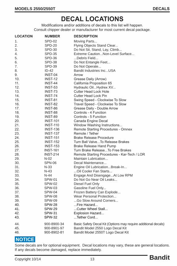
Bandit13Copyright 10/14
MODELS 2550/2550T
LOCATION NUMBER DESCRIPTION1. SPD-02 Moving Parts...2. SPD-20 Flying Objects Stand Clear...3. SPD-30 Do Not Sit, Stand, Lay, Climb...4. SPD-35 Extreme Caution...Non-Level Surface...5. SPD-36 ...Debris Field...6. SPD-38 Do Not Entangle Feet...7. SPD-39 Do Not Operate...8. ID-42 Bandit Industries Inc...USA9. INST-04 Arrow10. INST-12 GreaseDaily(Arrow)11. INST-44 CaliforniaProposition6512. INST-53 HydraulicOil...HydrexXV...13. INST-73 CutterHeadLockHole14. INST-74 CutterHeadLockPin15. INST-81 SwingSpeed-ClockwiseToSlow16. INST-82 TravelSpeed-ClockwiseToSlow17. INST-86 GreaseDaily-DoubleArrow18. INST-88 Controls-4Function19. INST-89 Controls-5Function20. INST-101 CanadaEngineDecal21. INST-110 WindowWashingInstructions...22. INST-136 RemoteStartingProcedures-Omnex23. INST-137 Remote/Tether24. INST-151 BrakeReleaseProcedure25. INST-152 TurnBallValve...ToReleaseBrakes26. INST-153 BrakeReleaseHandPump27. INST-161 TurnBrakeRelease...ToFreeBrakes28. INST-214 RemoteStartingProcedures-Kar-Tech/LOR29. N-02 Maintain Lubrication...30. SPN-06 Decal Maintenance...31. N-33 Engine Oil Lubrication...Break-In...32. N-43 ...Oil Cooler Fan Starts...33. N-44 Engage And Disengage...At Low RPM34. SPW-01 Do Not Go Near Oil Leaks...35. SPW-02 Diesel Fuel Only36. SPW-03 Gasoline Fuel Only...37. SPW-04 Frozen Battery Can Explode...38. SPW-08 Wear Personal Protection...39. SPW-09 ...Go Slow Around Corners...40. SPW-28 ...Fire Hazard...41. SPW-29 ...Cutter Wheel Stall...42. SPW-31 Explosion Hazard...43. SPW-32 ...TetherCord...
44. 900-8900-34 Basic Safety Decal Kit (Options may require additional decals)45. 900-8901-97 Bandit Model 2550 Logo Decal Kit46. 900-8902-81 BanditModel2550TLogoDecalKit
Some decals are for optional equipment. Decal locations may vary, these are general locations. If any decals become damaged, replace immediately.
DECALS
DECAL LOCATIONS
NOTICE
Modificationsand/oradditionsofdecalstothislistwillhappen.Consult chipper dealer or manufacturer for most current decal package.

Bandit14Copyright 10/14
MODELS 2550/2550T
EXAMPLES:
Decals located on your Bandit equipment contain useful information to assist you in operating your equipment safely. Some of the decals on your machine and their location are shown in this section. It is very important that all decals remain in place and in good condition on your machine. Please follow the care and instructions given below:
1. You should use soap and water to keep your decals clean. Never use mineral spirits or any other abrasive cleaners. 2. Replaceimmediatelyanymissingordamageddecals.Thelocationthedecalisgoingtobe applied to must be clean and dry, and at least 40°F (5°C) before applying decal. 3. When the need arises to replace a machine component with a decal attached, be sure and replace the decal. 4. Replacement decals are available, and can be purchased from the manufacturer or your Bandit Dealer. 5. Peelbackabouthalfofthebackerpaperonthedecal.Positionitontheflat,dry,cleansurfaceso it is smooth and secure. Peel off the remainder of the backer paper as you continue to stick the decal on the surface. 6. Rub decal from the center outward to remove air bubbles and to secure contact. 7. Combination English / Spanish decals are typically standard. Other foreign language decals are available and may be purchased. Mail translated decals required to Bandit Industries, Inc.
DECALS
DECALS

Bandit15Copyright 10/14
MODELS 2550/2550T
ENGINE OPERATING SPEEDS Refer to the Completion/Check Sheet, that is shipped with the machine for the correct engine rpm. If needed, contact your local dealer or Bandit Industries.NOTICE
CONTROLS
CONTROLS & COMPONENTS
LOCATION SHOWN
Basic Location of Controls and Components
SomeCurrentEngineTypes
Briggs & Stratton (Vanguard) 613477 - 35 Hp
Kohler CH980 - 38 Hp
KubotaV1505T-44.2Hp
Maximum RPM
3600
3600
3000
1. HydraulicTank 2. FuelTank 3. Oil Cooler Fan 4. Cutter Wheel Lock Pin 5. Cutter Wheel Lock Pin Hole
6. CutterWheelTeeth 7. Engine Controls (varies with engines) 8. Tach/HourMeter 9. Control Box
1 23
9
87
5
6
4

Bandit16Copyright 10/14
MODELS 2550/2550T CONTROLS
2550 CONTROLS - SWING OUT
LOCATION SHOWN 1. Swing Speed Control 2. TravelSpeedControl 3. Brake Release Valve 4. Cutter Wheel Engagement Lever 5. Steer Right / Left 6. TravelForward/Reverse 7. Cutter Down / Up 8. Grading Blade Down / Up 9. Swing Left / Right 10. Swing Out Lock Pin 11. Tach/HourMeter 12. Ignition Switch
Basic Location of Controls and Components
1
2
3
6 97 8
10
5
11
12
4

Bandit17Copyright 10/14
MODELS 2550/2550T CONTROLS
CONTROL OPERATING PROCEDURES - SWING OUT 1. Swing Speed Control: Theswingspeedcontrolstheratethecutterwheelpassesthroughthestump.Todecreasetheswing speed, turn the control knob clockwise.
2. Travel Speed Control: Thetravelspeedcontrolstheratethemachineapproachesthestump.Todecreasethetravelspeed, turn the control knob clockwise.
3. Brake Release Valve: Turn3to4fullrevolutionswhenmovingthemachinewithoutpower.
4. Cutter Wheel Engagement Lever: Before engaging or disengaging the cutter wheel, make sure the engine is at an idle.Toengage thecutterwheel,pressthebuttonontopoftheleverandpullthelever,towardstheoperator.Todisengage the cutter wheel, press the button on top of the lever and push the lever, away from the operator.
5. Steer Right / Left: Tosteerthemachinetotheright,pushthehandle,awayfromtheoperator.Tosteerthemachineto theleft,pullthehandle,towardstheoperator.Thesteeringisstationarywhenthehandleisinthecenter location.
6. Travel Forward / Reverse: Tomovethemachineforward,pushthehandleawayfromtheoperator.Toreversethemachine,pullthe handletowardstheoperator.Themachineisstationarywhenthehandleisinthecenterlocation.
7. Cutter Down / Up: Tolowerthecutterwheel,pushthehandleawayfromtheoperator.Toliftthegradingblade,pullthe handletowardstheoperator.Thegradingbladeisstationarywhenthehandleisinthecenterlocation.
8. Grading Blade Down / Up: Tolowerthegradingblade,pushthehandleawayfromtheoperator.Toliftthecutterwheel,pullthe handletowardstheoperator.Thecutterwheelliftisstationarywhenthehandleisinthecenterlocation.
9. Swing Left / Right: Toswingthecutterwheeltotheleft,pushthehandle,awayfromtheoperator.Toswingthecutterwheel totheright,pull thehandle, towardstheoperator. Theswing is stationarywhenthehandle is in the center location.
10. Swing Out Lock Pin: Lock the swing out lock pin into the operating position or the transport position.
11. Tach / Hour Meter: Displays the engine rpm and number of hours the engine has been on. Varies with engines and options.
12. Ignition Switch: Location varies with different engine options.

Bandit18Copyright 10/14
MODELS 2550/2550T CONTROLS
2550 CONTROLS - REMOTE
LOCATION SHOWN 1. EngineThrottle 2. Remote/TetherSwitch 3. Ignition Switch 4. Tach/HourMeter 5. Link Light 6. TetherPlugJack 7. Cutter Wheel Engagement Lever
Basic Location of Controls and Components
16. Steer Right / Left 17. TongueOut/In 18. Status Light 19. Cutter Bump Adjustment 20. Power On / Off 21. Batteries 22. Battery Status Light
8. Swing Speed Control 9. Brake Release Valve 10. TravelSpeedControl 11. Cutter Down / Up 12. Swing Left / Right 13. Drive Forward / Reverse 14. Blade Down / Up 15. Engine Stop
LORRemoteTransmitter
13 15 16
11 17 18 14 12
19 20
21
TetherControl11 12
13 14 15 16
1 2 3 4 5 6 7
8 9 10
KAR-TECHRemoteTransmitter
1918 22 20
11 13 14 16 12
15

Bandit19Copyright 10/14
MODELS 2550/2550T CONTROLS
CONTROL OPERATING PROCEDURES - REMOTE 1. Engine Throttle: Varies with different engines, refer to engine manual. 2. Remote / Tether Switch: If the switch is in the remote position, the machine is controlled by the transmitter. If the switch is in the tether position and the tether cord is plugged in to the jack, the machine is controlled by the tether. 3. Ignition Switch: Location varies with different engine options. 4. Tach / Hour Meter (not shown): Displays the engine rpm and number of hours the engine has been on. Varies with engines and options. 5. Link Light: If the transmitter is linked to the machine the link light will be on. 6. Tether Plug Jack: Plug the tether cord in here to control the machine if the batteries in the remote control run out of power or the remote is not working. 7. Cutter Wheel Engagement Lever: Before engaging or disengaging the cutter wheel, make sure the engine is at an idle.Toengagethecutterwheel,pressthebuttonontopoftheleverandpullthe lever,towardstheoperator.Todisengagethecutterwheel,pressthebuttonontopoftheleverandpush the lever, away from the operator. 8. Swing Speed Control: Theswingspeedcontrolstheratethecutterwheelpassesthroughthestump. Todecreasetheswingspeed,turnthecontrolknobclockwise. 9. Brake Release Valve: Turn3to4fullrevolutionswhenmovingthemachinewithoutpower.10. Travel Speed Control:Thetravelspeedcontrolstheratethemachineapproachesthestump.Todecrease the travel speed, turn the control knob clockwise. 11. Cutter Down / Up:Tolowerthecutterwheel,pushtheswitchawayfromtheoperator.Toliftthecutter wheel,pulltheswitchtowardstheoperator.Thecutterwheelliftisstationarywhentheswitchisinthe center location. When using a transmitter, if you hit and release the lift down switch, the cutter wheel will drop a certain distance that is adjustable using the cutter bump adjustment.12. Swing Left / Right: Toswingthecutterwheeltotheleft,pushtheswitch,awayfromtheoperator.To swingthecutterwheeltotheright,pulltheswitch,towardstheoperator.Theswingisstationarywhen the switch is in the center location.13. Drive Forward / Reverse: Tomovethemachineforward,pushtheswitchawayfromtheoperator.To reversethemachine,pulltheswitchtowardstheoperator.Themachineisstationarywhentheswitchis in the center location.14. Grading Blade Up / Down (Optional): If equipped, to lower the grading blade, push the switch away from theoperator.Toliftthegradingblade,pulltheswitchtowardstheoperator.Thegradingbladeisstationary when the switch is in the center location.15. Engine Stop Switch:Shutsoffthepowertotheengineandtothehydraulicvalve.Theenginestopswitch must be in the run position on the tether control or the center position on the remote transmitter for the engine to start.16. Steer Right / Left: With the remote transmitter, to steer the machine to the left, push the switch, away fromtheoperator.Tosteerthemachinetotheright,pulltheswitch,towardstheoperator.Thesteering is stationary when the switch is in the center location. Withatethercontrol,tosteerthemachinetotheright,pushtheswitch,awayfromtheoperator.Tosteer themachinetotheleft,pulltheswitch,towardstheoperator.Thesteeringisstationarywhentheswitch is in the center location.17. Tongue Out / In: Not used on this model.18. Status Light: Ifthetransmitterisworkingproperlythestatuslightwillbegreenandflashing.Seethe LOR manual for further information.19. Cutter Bump Adjustment: Turntheknobclockwisetoincreasethedistancethecutterwheeldropswhen you hit the cutter wheel up and down or lift control switch and counter-clockwise to decrease the cutter wheel drops.20. Power On / Off Switch: Toswitchtheremotetransmittertoon,pushtheswitchawayfromtheoperator.Toswitchtheremote transmitter to off, pull the switch towards the operator.21. Batteries: LOR remote transmitters require (4) AA batteries.22. Batteries Status Light:Kar-Techremotewillhaveablinkingredlightwhenbatteryisgettinglow.

Bandit20Copyright 10/14
MODELS 2550/2550T CONTROLS
2550T CONTROLS - SWING OUT
LOCATION SHOWN 1. TravelSpeedControl 2. Swing Speed Control 3. Cutter Wheel Engagement Lever 4. LeftTrackForward/Reverse 5. RightTrackForward/Reverse 6. Cutter Down / Up 7. Grading Blade Down / Up 8. Swing Left / Right 9. Swing Out Lock Pin 10. Tach/HourMeter 11. Ignition Switch
Basic Location of Controls and Components
1
2
5 86 7
9
4
10
11
3

Bandit21Copyright 10/14
MODELS 2550/2550T CONTROLS
CONTROL OPERATING PROCEDURES - SWING OUT 1. Travel Speed Control: Thetravelspeedcontrolstheratethemachineapproachesthestump.Todecreasethetravelspeed, turn the control knob clockwise.
2. Swing Speed Control: Theswingspeedcontrolstheratethecutterwheelpassesthroughthestump.Todecreasetheswing speed, turn the control knob clockwise.
3. Cutter Wheel Engagement Lever: Before engaging or disengaging the cutter wheel, make sure the engine is at an idle.Toengage thecutterwheel,pressthebuttonontopoftheleverandpullthelever,towardstheoperator.Todisengage the cutter wheel, press the button on top of the lever and push the lever, away from the operator.
4. Left Track Forward / Reverse: Tomovethelefttrackforward,pushthehandleawayfromtheoperator.Toreversethelefttrack,pullthe handletowardstheoperator.Thetrackisstationarywhenthehandleisinthecenterlocation.
5. Right Track Forward / Reverse: Tomovetherighttrackforward,pushthehandleawayfromtheoperator.Toreversetherighttrack,pull thehandletowardstheoperator.Thetrackisstationarywhenthehandleisinthecenterlocation.
6. Cutter Down / Up: Tolowerthecutterwheel,pushthehandleawayfromtheoperator.Toliftthegradingblade,pullthe handletowardstheoperator.Thegradingbladeisstationarywhenthehandleisinthecenterlocation.
7. Grading Blade Down / Up: Tolowerthegradingblade,pushthehandleawayfromtheoperator.Toliftthecutterwheel,pullthe handletowardstheoperator.Thecutterwheelliftisstationarywhenthehandleisinthecenterlocation.
8. Swing Left / Right: Toswingthecutterwheeltotheleft,pushthehandle,awayfromtheoperator.Toswingthecutterwheel totheright,pull thehandle, towardstheoperator. Theswing is stationarywhenthehandle is in the center location.
9. Swing Out Lock Pin: Lock the swing out lock pin into the operating position or the transport position.
10. Tach / Hour Meter: Displays the engine rpm and number of hours the engine has been on. Varies with engines and options.
11. Ignition Switch: Location varies with different engine options.

Bandit22Copyright 10/14
MODELS 2550/2550T CONTROLS
2550 CONTROLS - REMOTE
LOCATION SHOWN 1. EngineThrottle 2. Remote/TetherSwitch 3. Ignition Switch 4. Tach/HourMeter 5. Link Light 6. TetherPlugJack 7. Cutter Wheel Engagement Lever
Basic Location of Controls and Components
15. RightTrackForward/Reverse 16. Status Light 17. Cutter Bump Adjustment 18. Battery Status Light 19. Power On / Off
8. TravelSpeedControl 9. Swing Speed Control 10. Cutter Down / Up 11. Swing Left / Right 12. LeftTrackForward/Reverse 13. Blade Down / Up 14. Engine Stop
TetherControl10 11
12 13 14 15
1 2 3 4 5 6 7
KAR-TECHRemoteTransmitter
1716 18 19
10 12 13 15 11
14
8
9
Tolinkthetransmitterandthemachine:1. Switch the transmitter power on2.SwitchtheTETHER/REMOTEswitchon themachinetotheREMOTEposition3.TurntheignitionkeytotheONposition4. When the machine link light turns on, start engine.
NOTICE

Bandit23Copyright 10/14
MODELS 2550/2550T CONTROLS
CONTROL OPERATING PROCEDURES - REMOTE 1. Engine Throttle: Varies with different engines, refer to engine manual. 2. Remote / Tether Switch: If the switch is in the remote position, the machine is controlled by the transmitter. If the switch is in the tether position and the tether cord is plugged in to the jack, the machine is controlled by the tether. 3. Ignition Switch: Location varies with different engine options. 4. Tach / Hour Meter (not shown): Displays the engine rpm and number of hours the engine has been on. Varies with engines and options. 5. Link Light: If the transmitter is linked to the machine the link light will be on. 6. Tether Plug Jack: Plug the tether cord in here to control the machine if the batteries in the remote control run out of power or the remote is not working. 7. Cutter Wheel Engagement Lever: Before engaging or disengaging the cutter wheel, make sure the engine is at an idle.Toengagethecutterwheel,pressthebuttonontopoftheleverandpullthe lever,towardstheoperator.Todisengagethecutterwheel,pressthebuttonontopoftheleverandpush the lever, away from the operator. 8. Travel Speed Control:Thetravelspeedcontrolstheratethemachineapproachesthestump.Todecrease the travel speed, turn the control knob clockwise. 9. Swing Speed Control: Theswingspeedcontrolstheratethecutterwheelpassesthroughthestump. Todecreasetheswingspeed,turnthecontrolknobclockwise.10. Cutter Down / Up:Tolowerthecutterwheel,pushtheswitchawayfromtheoperator.Toliftthecutter wheel,pulltheswitchtowardstheoperator.Thecutterwheelliftisstationarywhentheswitchisinthe center location. When using a transmitter, if you hit and release the lift down switch, the cutter wheel will drop a certain distance that is adjustable using the cutter bump adjustment.11. Swing Left / Right: Toswingthecutterwheeltotheleft,pushtheswitch,awayfromtheoperator.To swingthecutterwheeltotheright,pulltheswitch,towardstheoperator.Theswingisstationarywhen the switch is in the center location.12. Left Track Forward / Reverse: Tomovethelefttrackforward,pushtheswitchawayfromtheoperator.To reversethelefttrack,pulltheswitchtowardstheoperator.Thelefttrackisstationarywhentheswitchis in the center location.13. Grading Blade Up / Down (Optional): If equipped, to lower the grading blade, push the switch away from theoperator.Toliftthegradingblade,pulltheswitchtowardstheoperator.Thegradingbladeisstationary when the switch is in the center location.14. Engine Stop Switch:Shutsoffthepowertotheengineandtothehydraulicvalve.Theenginestopswitch must be in the run position on the tether control or the center position on the remote transmitter for the engine to start.15. Right Track Forward / Reverse: Tomovetherighttrackforward,pushtheswitchawayfromtheoperator.To reversetherighttrack,pulltheswitchtowardstheoperator.Therighttrackisstationarywhentheswitchis in the center location.16. Status Light: Ifthetransmitterisworkingproperlythestatuslightwillbegreenandflashing.Seethe LOR manual for further information.17. Cutter Bump Adjustment: Turntheknobclockwisetoincreasethedistancethecutterwheeldropswhen you hit the cutter wheel up and down or lift control switch and counter-clockwise to decrease the cutter wheel drops.18. Batteries Status Light:Kar-Techremotewillhaveablinkingredlightwhenbatteryisgettinglow.19. Power On / Off Switch: Toswitchtheremotetransmittertoon,pushtheswitchawayfromtheoperator.Toswitchtheremote transmitter to off, pull the switch towards the operator.

Bandit24Copyright 10/14
MODELS 2550/2550T
CONSULT THE ENGINE MANUFACTURER’S MANUAL FOR SPECIFIC CONTROLS, OPERATION, &
MAINTENANCE FOR TYPICAL ENGINES1. Ignition Switch: Turntheignitionswitchkeyclockwiseonestop(onposition)toturntheelectricalsystem on.Thekeyshouldremainintheonpositionwhiletheengineisrunning.Turnthekeyfullyclockwise (startposition)thiswillstarttheengine.Toshutofftheengine,returnthekeytotheoffposition.
2. On/Off Switch - Push Button Start: SomegasolineenginesmayhaveaToggleSwitchoranOn/Off Switchcombinedwithapushbuttontostarttheengine.FirstturntheOn/OffSwitchorToggleSwitchto the on position, then depress and hold the Push Button Start until the engine starts, then release the button.Toshutofftheengine,returntheOn/OffSwitchorToggleSwitchtotheoffposition.
3. Ignition Switch With Preheat: Thetypicaldieselenginemayhaveapreheatsystemtoassistinstarting theengineduringcoldweather.Toactivatethepreheatsystem,continuetoholdtheignitionkeyinthe preheat position for 15 to 20 seconds, then attempt to start the engine. If the engine fails to start within 15 seconds, return the key to the preheat position, hold 10 seconds, and try starting again.
4. Choke Adjustment (if equipped): Some gasoline engines may have a choke adjustment, pull the choke lever out to choke the engine. Push the choke lever in for normal engine operations.
5. Throttle Adjustment (if equipped): Some engines may have a knob or a handle for the throttle adjustment. Typicallyyouwouldpulltheknobout,orturnthehandletoincreasetheengineR.P.M.’s.Todecrease you would push in the knob or turn the handle the opposite way.
6. “Bandit” Lever Lock Cable Throttle System (if equipped): TheBanditthrottlesystemhas(2)positions, HIGH and LOW. Engine R.P.M. is controlled by moving the lever from one position to the other.
7. Push Button Or Electric Throttle System (if equipped): Some engines may have a push button or electric throttle adjustment. Engine R.P.M. is controlled by pushing a button or switch to raise or lower the R.P.M.
8. Alternator Warning Light: Thislightwillglowwhenthealternatorisnotcharging,orwhentheignition switch is turned on and the engine is not running.
9. Oil Pressure Warning Light: Thislightwillglowwhentheoilpressureistolow,orwhentheignition switch is turned on and the engine is not running.
10. Engine Temperature Warning Light: Thislightwillglowwhentheengine,orenginecoolant,isabove normal operating temperature. If this occurs allow the engine temperature to cool down. If the engine is overheating because of a loss of coolant, or a broken fan belt, shut the engine off immediately.
TYPICALGASOLINEENGINE
TYPICALDIESELENGINES
BANDITTHROTTLESYSTEM PUSHBUTTONORELECTRICTHROTTLESYSTEM
CONTROLS
NOTICEMost engines have an automatic low oil pressure shut down device, but some engines do not for example the Lombardini 9LD. Expensive damage may occur if the engine oil level and condition is not checked daily. Followallmaintenanceproceduresspecifiedbytheenginemanufacturer’smanual.Checkthefuelleveldaily,runningoutandreprimingistimeconsuming.Donotoverfillthetank,theremustbeexpansionspaceinthetopofthetank.Inspecthoses,fittings,lines,tanks,etc.foranyoil,fuel,enginecoolant,etc.leaksdaily.Repair or replace any damaged or leaking components.

Bandit25Copyright 10/14
MODELS 2550/2550T MACHINE OPERATION
MACHINE OPERATION• Checkallfluidsbeforestartingthemachine.• Makesuretogothroughthedailystart-upandmaintenanceproceduresbeforeoperatingthemachine.• Cutterwheelmustbedisengagedbeforestarting.• Startengineatidlespeedandallowforsufficienttimeforoiltocirculatebeforeproceeding.• Testallcontrolsforproperoperation.• Avoidtransversingslopes.
DO NOT OPERATE AROUND WATER, GAS, POWER OR PHONE LINES. IF IN DOUBT, CHECK BEFORE GRINDING.
WEAR ALL PERSONAL PROTECTIVE EQUIPMENT PER ANSI, OSHA AND MANUALS.
KEEP CLEAR OF CUTTING WHEEL, MOVING MACHINE PARTS AND GRINDER DEBRIS FIELD.
DANGER!
DANGER!
DANGER!
Position machine at stump with cutter wheel a slight distance away from stump.
Reduce engine RPM to idle.
If equipped, position the swing out in the operating position and lock the spring loaded pin. Also unpin the swing out chip curtain.
Raise cutter wheel clear of stump.
Engage the cutter wheel.
Increase engine RPM to full.
Testthecontrolsforproperoperation,speed,and unobstructed movement.
Thecutterwheelswingspeedshouldbeadjustedto a rate that will allow cutter wheel to pass through stumpsmoothly.Ifjerking,bouncingorsignificantdrops in engine speed occur, swing rate is too rapid and must be decreased.
Swing speed should be determined and adjusted with the controls in the full open position.
A swing speed control is located on the side of the control box of the machine to adjust this speed. Turningthedialclockwisewillslowtheswingaction.
Travelspeedshouldbeadjustedtoaratethatwill allow cutter wheel to approach stump smoothly. If cutter wheel is approaching stump quickly, travel speed is too rapid and must be decreased.
Travel speed shouldbedeterminedandadjustedwith the controls in the full open position.
A travel speed control is located on the side of the control box of the machine to adjust this speed. Turningthedialclockwisewillslowthetravelspeed,depending on the type of controls and when the machine was built.
Lower the spinning cutter wheel to the stump and make a few light passes at the stump to get a feel for the cutting action. Gradually increase cutting action and work away at the stump by swinging cutter wheel left-to-right-to-left through stump in a sideways motion. Smooth, effortless cutting lengthens machine life, minimizes downtimeandismoreprofitableinthelongrun.Continue cutting stump by adjusting cutting wheel progressively lower until stump is cut well below ground level.Swing cutter wheel clear of stump and position machine closer to stump for next series of passes and continue cutting. If the machine is equipped with a tongue extension, reposition the cutter wheel with the tongue extension control.Continue in this manner until stump has been removed.Larger stumps may require repositioning machine to remove complete stump.Raise cutter wheel clear of stump and return to center position.Reduce engine speed to idle and disengage cutter wheel. DO NOT TURN OFF MOTOR. Engine should be allowed to cool slowly at idle for 3-5 minutes to avoid damage.DO NOT ENGAGE OR DISENGAGE CUTTER WHEEL AT A HIGH ENGINE SPEED. Damage to machine will occur.At low engine RPM, the cutter wheel swing speed control needs to be closed or slowed all the way downforthecutterheadtoswing.Thedirectionthecontrol knob needs to be turned will depend on the type of controls and when the machine was built.Turnoffengine.Allow cutter wheel to come to a complete stop before inspecting.

Bandit26Copyright 10/14
MODELS 2550/2550T
For optimum performance, the stump should be cut with the portion of the cutter wheel shown below. NEVER UNDERCUT THE STUMP. Undercutting the stump may cause severe kickback, vibration and component damage. NEVER CUT THE STUMP FROM THE TOP.Thecutterwheelwillthrowdebrisupandtowardtheoperator, instead of down and under the machine.
MACHINE OPERATION
CUTTING AREADANGER!
90°CUTTING
AREA

Bandit27Copyright 10/14
MODELS 2550/2550T
1. Close the needle valve (see Figure 1) by turning the knob clockwise 3 to 4 full turns. It will be located near the side of the control cabinet. 2. Close the ball valve located between the control cabinet and the hydraulic tank, see Figure 2. 3. Pumpthebrakerelease2to4pumps.Thebrakereleaseislocatedinsideofthecontrolcabinet.See Figure 3. 4. Themachineisnowinfreewheelmode,althoughtherewillbedragfromthedrivewheelmotor. 5. Reverse steps 2 and 1 after moving the machine.
Use this procedure only when the machine will not start or run to help prevent damage to the hydraulic system. With the key in the “off” position and in your possession, follow the steps below:
MACHINE OPERATION
MOVING A MACHINE WITHOUT POWER(MODEL 2550)NOTICE
Brake Release
FIGURE 1 FIGURE 2
FIGURE 3
Turn clockwise 3 to 4 full
turns.
Ball Valve
Swing-Out Control Machine Remote Control Machine
Brake Release

Bandit28Copyright 10/14
MODELS 2550/2550T
BEFORE TRANSPORTING THE MACHINE, INSPECT AND CONFIRM THE FOLLOWING STEPS:
TRANSPORTATION PROCEDURES
TRANSPORTATION PROCEDURESWARNING!
1. Thetrailerhasacargoweightratingcapacityfortheweightofthestumpgrinder.Thecombinedweight of the trailer and the stump grinder can not exceed the load capacity of the tires, axles, hitch coupler system or the GVWR (Gross Vehicle Weight Rating) of the trailer.2. The towing vehicle is rated for and has the towing capabilities to haul the stump grinder package (includesthestumpgrinderandatrailer).Thetowingvehiclemustbemechanicallysoundandcapable of handling the towing job.3. Thehitchonthetowingvehicleandthecoupleronthetrailerisaperfectmatchinsize,type,andneeded capacity.4. Both the towing hitch and the coupler are in good mechanical and wear condition, that they are joined together securely, and the coupler/hitch is locked in place.5. Thesafetychainshavethecorrectcapacityfortheequipmentbeingtowed.6. Thesafetychainsarecrossedunderthecoupler/hitchthensecurelyattachedtothetowingvehicle.The safety chains are long enough to not restrict the turning movement, but short enough to not drag on the road.7. Theelectricalplug-inonthetowingvehicleandthetrailerarewiredforthesamefunctionsandtheyfit securely together. The plug-in wire is long enough to not restrict the turningmovement, but short enoughtonotdragontheroad.Thetrailermusthavealightingsystemandbrakingsystemtomatchand perform correctly off the towing vehicles system. You must meet the Federal and your States’ Department ofTransportationCodeofRegulationsconcerninglights,brakes,andhighwaytransit.8. Thebreak-awayactuator(ifequipped)thatisinstalledonthetrailercorrectlyworksandisappropriately attached to the towing vehicle.9. All lights and brakes on the trailer correctly functions when activated by the systems in the towing vehicle.10.Thetireshavebeencheckedforcutsordamagedrims,airpressureiscorrect,andtheaxlelugnutshave been checked for correct torque (refer to trailer manual).11. When the stump grinder is on the trailer, the trailer has the right load capacity, the stump grinder is positioned on the trailer for the correct weight distribution (there should be about 15% of the total stump grinder package weight on the tongue or hitch), the stump grinder brakes are locked, the cutter wheel is resting on the trailer bed, and the stump grinder is securely bound down to the trailer bed per your States binding requirements.12. Any loose debris, tools or parts have been cleared off or are put away.13. Close and secure any of the following if equipped: tool box, battery box, engine cowl doors and side panels, radiator debris screens, inspection doors, cabinet doors, housing covers, tank caps and covers, vise, etc.14. Make sure the load ramps are securely stored for transport.15. Make sure the stump grinder’s engine is not running, the ignition key is in your possession, and all controls are stored correctly and locked in place for transport.16.Thestumpgrinderpackagemustbehauledlevelandthetowingvehiclemustbesizedtohandlehitch weightandtowingweight.Thetowingvehicleorthecombinationoftowingvehicleandtowingpackage musthaveenoughbrakingcapacitytomeettheFederalandyourStateDepartmentofTransportation requirements.17.Thestumpgrinderpackageisnowreadyfortransport.Makesuretoobeyalllocalregulationandlaws regarding the transporting of this type of machine.18. Do not drive too fast for road conditions or exceed speed regulations for equipment towing.

Bandit29Copyright 10/14
MODELS 2550/2550T TRANSPORTATION PROCEDURES
LOADING & UNLOADING
BEFORE LOADING OR UNLOADING THE MACHINE, INSPECT AND CONFIRM THE FOLLOWING STEPS: Whenloadingorunloadingtheself-propelledmachineonthetrailer,usecareandcaution.Themaneuvering of the equipment must be slow, smooth, and intentional, not fast and jerky.
WARNING!
1. Makesurethetrailerandtowingvehicleareparkedonaflatsurface.Theymustbestableonthesurface with the brakes locked and/or the wheels chocked to avoid unwanted movement.
2. Position the loading ramps or loading gate securely between the trailer and the ground level. Have them located so that they are in line with the tires or tracks of the machine when it moves.
3. Remove and store the chains and binders used for transporting.
4. Confirmthattherearenotanyobstaclesonthetrailerbed,aroundthetrailerthatmaycauserestricted movement of the machine or the operator.
5. Theonlypersonintheareashouldbetheonethatisoperatingthemachinecontrols,andhe/sheshould be very experienced with the controls on this machine.
6. If you are on streets, roads or public areas, position the warning cones etc, per your company’s safety policy.
7. Follow all pre-startup instructions for the machine.
8. Once the engine is running at as low a speed as possible, carefully raise the cutter wheel slightly up off the ground or trailer bed. While loading or unloading the stump grinder, the cutter wheel should not be raised any higher than necessary to just clear whatever is under it. You need to keep the weight center of gravity as low as possible to avoid tipping the machine while it is moving.
9. Thecutterwheelendofthestumpgrindershouldalwaysbepositionedsothatitistowardtherearofthe trailer, not the tongue, during transport.
10. When the machine is positioned on the trailer bed, there should be about 15% of the total trailer package weight on the tongue or hitch.
11.Alignthemachinewiththetrailerbed,andtheloadingramps.Theonlyequipmentmovementshouldbe slowly, straight on or straight off the trailer.
12. With the engine and the machine at as low of speed as possible, move the machine toward the ramp system. Make sure the alignment is correct throughout the travel, and carefully readjust the cutter wheel height so that it barely clears obstacles as it is going up or down the ramp system.
13. Properly secure the equipment and the area to avoid any possible accidents or dangers.
14.The trailershouldbeconstructedwithappropriatechaindownpositions for thespecificsizedstump grinder. You must have binders that will withstand the strain of the machine trying to move while it is being transported.
15.Theloadingrampsorloadinggateofthetrailermustbeconstructedtowithstandtheweightandforces involved in loading and unloading the machine.
Never load or unload the machine with the drive lock pin pulled out of the rim. Make sure the drive lock pin is in all the way.
DANGER!

Bandit30Copyright 10/14
MODELS 2550/2550T
Consult your engine manual for proper break-in procedures. Various engines require somewhat different procedures,butbasicallytheenginesneedtooperateatlowerR.P.M.’sandloadsforaspecifictime.
Failure to properly break-in your engine may result in poor bearing and piston ring surfaces.
TheBandithasonlybeenrunforashorttimetotestproperhydraulicpressures,possibleleaks,etc.Thefueltankwillbeempty.Fuelisprovidedthroughasmallauxiliarytankfortesting.Thisimmenselyhelpsmaintain safety in our manufacturing facility and while shipping.
Do not let anyone operate or maintain this machine until they have thoroughly read this manual, reviewed the equipment decals, watched the equipment video, and has been properly trained. You can purchase additional Bandit manuals, decals and videos for a nominal fee.
Expensive damage to the Bandit will occur if proper preparation is not taken before welding on the machine. Be sure to disconnect both battery cables and the engine ECM (engine control module) before welding. Follow thespecificEngineMFG.instructionsforproperweldingandgroundingprocedures,beforeattemptingtoweldon the machine. If welding on the machine, do not ground the welder through the machine bearings, ground near work to be performed.
MAINTENANCE SECTIONMAINTENANCE SECTION
TheBandit is a very simplemachine tomaintain. If youwill followa regular scheduledpreventative maintenance program, you should have years of trouble free operation.
DANGER!
NOTICE
NOTICE
NOTICE
NOTICE
1. Check the safety decals and engine gauges:Replace any missing or damaged decals and/or engine gauges.
2. Check all safety equipment:Check for proper operation. Repair or replace as needed.
3. Check entire machine for loose bolts, nuts, parts, or components:Check entire machine for any loose parts or components.Checkforloosenutsorbolts.Torque,tighten, or replace any of the loose components. See page35forspecificbolttorques.
4. Check all guards:Check to make sure all guards are in place and installed correctly. Make sure they are secure.
5. Check the cutter wheel and pockets for wear:Check for elongated bolt holes, secure welds, torqued bolts, excessive wear, and impact cracks. If a problem is found, contact the grinder manufacturer or an authorized Bandit dealer.
6. Check condition of cutter teeth. pockets, and hardware:Sharpen or replace your cutter teeth to keep them sharp. Check the condition of your teeth, pockets, and hardware. Replace if necessary.
7. Check cutter wheel pocket bolts:All cutter wheel pockets bolts must be factory approved. Bolts must be replaced after a maximum of 4-5 rotations/changes to ensure safe clamping ability.
SeeTorqueChartforpropertorque.
DAILY START UP & MAINTENANCE
Before attempting any type of maintenance disengage clutch, turn off engine, wait for the cutter wheel to come to a complete stop, install the cutter wheel lock pin, place the cutter wheel on the ground, disconnect battery, and make sure the ignition key is in your possession.
DANGER!

Bandit31Copyright 10/14
MODELS 2550/2550T MAINTENANCE SECTION
15. Check oil cooler:Thoroughlycleancoolerfinsatleastonceadayormore in excessive conditions. Make sure debris isnotpackedbetweenfins. Usecompressedair and/or pressurized water (soap may also be needed) to clean the oil cooler, depending on the level and type of debris. If pressurized water is used, be careful not to turn the debris hard and pack solidbetweenthecoolerfins.Makesuretocleanthe cooler in the correct direction; do not propel the debris into the cooler with compressed air or pressurized water. Keep the compressed air or pressurized water a safe distance from the cooler finssotheyarenotdamaged.Visuallyinspectthecoolerfinsandmakesuretheyarenotbentorclosedoff, repair or replace as needed.
16. Check air cleaner or precleaner:Clean or replace element following engine manual recommendations. Also, check and clean the vacuator valve.
17. Check tires (Model 2550):Check tires for wear, weather checking and damage. Replace if damaged.
18. Inspect axle dust caps (Model 2550):Inspect axle dust caps and replace if damaged or leaking.
19. Check tracks (Model 2550T):Check track tension, should have approximately 1/4” (6mm)ofdeflectionwith10 lbs (4.5kg)of force.Adjust as necessary. Also check tracks for wear, weather checking and damage. Replace if damaged.
20. Check around machine:Check around the entire machine for tools, cans, saws, etc. All tools not in use should be stored in a tool box.
21. Review all safety procedures on decals, from manual, and from video.
22. Make sure all safety equipment is being worn:Make sure you are wearing all of your safety equipment: hard hat, face shield, gloves, eye protection, ear protection, etc. per ANSI and OSHA standards.
23. Remember to check EVERYTHING on the checklist.
8. Grease cutter wheel arm pivot bushings:Grease cutter wheel arm pivot bushings with 1 to 2 shots of EP-2 Lithium type grease. Wipe off excess grease. Excessive grease will attract dirt.
9. Check hydraulic oil level:Thehydraulicoilreservoirtanklevelshouldalwaysremain at 7/8 full. Remember to check DAILY to avoid excessive heat build up.
10. Check for any fluid leaks:Inspect for any oil, fuel, hydraulic oil, or engine coolantleaks.Checkallhoses,fittings,lines,andtanks. DONOTuse fingers or skin to check for hydraulic leaks. Repair or replace any damaged or leaking components.
11. Check hydraulic control valves:Inspect all hydraulic control valves and ensure they operate smoothly and shift correctly.
12. Check the fuel level:Check the fuel level, running out and repriming is timeconsuming.Donotoverfill,andyoumustleavefuel expansion space in the top of the tank.
13. Check engine oil and coolant level:Fol low the engine manufacturer manual recommendationsforfluidlevels.YouMUST follow specificENGINEMFG.manual recommendationsfor radiator coolant, additives, lubrication, correct enginespeed,ETC.
14. Check radiator, debris screen:Thoroughlycleanradiatorfinsatleastonceadayor more in excessive conditions. Make sure debris isnotpackedbetweenfins. Usecompressedair and/or pressurized water (soap may also be needed) to clean the radiator, depending on the level and type of debris. If pressurized water is used, be careful not to turn the debris hard and pack solid between the radiatorfins. Makesure toclean the radiatorin the correct direction depending on if the cooling fan is a sucker or a pusher; do not propel the debris into the radiator with compressed air or pressurized water. A partially plugged radiator will not allow the engine to cool properly. Keep the compressed air or pressurized water a safe distance from the radiator fins so they are not damaged. Visually inspecttheradiatorfinsandmakesure theyarenotbentor closed off, repair or replace as needed. Clean cooling fan, shroud on air cooled engines, and the debris screen (if so equipped). Improper service, maintenance, or neglect will cause overheating problems and/or engine failure. Refer to the engine manufacturer’s manual.
DAILY START UP & MAINTENANCE (cont.)

Bandit32Copyright 10/14
MODELS 2550/2550T MAINTENANCE SECTION
1. Grease swing pivot assembly bushings:Grease the top and bottom swing pivot assembly bushings with 1 to 2 shots of EP-2 Lithium type grease. Wipe off excess grease. Excessive grease will attract dirt.
2. Grease steering axle pivot bushings (Model 2550):Grease steering axle pivot bushings with 1 to 2 shots of EP-2 Lithium type grease. Wipe off excess grease. Excessive grease will attract dirt.
3. Grease steering bushings (Model 2550):Grease steering bushings with 1 to 2 shots of EP-2 Lithium type grease. Wipe off excess grease. Excessive grease will attract dirt.
4. Grease cylinder lug pin bushings:Grease cylinder lug pin bushings with 1 to 2 shots of EP-2 Lithium type grease. Wipe off excess grease. Excessive grease will attract dirt.
5. Grease swing out pivot bushings:Grease swing out pivot bushings with 1 to 2 shots of EP-2 Lithium type grease. Wipe off excess grease. Excessive grease will attract dirt.
6. Lubricate all steel friction areas::Lubricate all steel friction areas including , but not limited to pivoting, hinged, sliding, rotating areas on the machine (i.e. cutter wheel guard, control box doors, etc.).
7. Check the cutter wheel hydraulic motor coupler:Remove the cover plate over the cutter wheel hydraulic motor coupler and check the torque of the couplerbolts,seeTorqueChart.
8. Check and retighten tank mount bolts:Check and retighten the fuel tank and hydraulic tank mount bolts.
9. Check alternator and fan belts on engine (as applicable):Adjust and maintain per the engine manufacturer’s manual.
10. Check wheel lug nuts (Model 2550):Keep lug nuts tight, retorque, replace if needed.
WEEKLY MAINTENANCE
1. Grease grading blade bushings (if equipped):Grease steering axle pivot bushings with 1 to 2 shots of EP-2 Lithium type grease. Wipe off excess grease. Excessive grease will attract dirt.
2. Lubricate cutter wheel engagement lever cable:Lubricate cutter wheel engagement lever cable and cable ends with a cable lube or SAE 10W/30 oil. Replace cutter wheel engagement lever cable if it doesn’t operate smoothly.
3. Tire air pressure (Model 2550):Fill each tire to rated capacity on tire.
4. Check hydraulic function pressures:Check, reset and maintain all hydraulic function pressure settings to amaximumof the specified PSI(bar).Thiswillgiveyouthebestperformancefrom the hydraulic system.
MONTHLY MAINTENANCE
1. Grease steering wheel hub bearings (Model 2550 with 2 Wheel Drive):Inspect and clean the steering wheel hub bearings, cups, and seals. Replace seals if ever removed. Replace bearings and cups as needed. Grease the wheel bearings with an EP-2 Lithium type grease. Remove rubber plug and pump grease into E-Z Lube zerk until all of the old grease is pumped out of the dust cap. Wipe off excess grease. Excessive grease will attract dirt.
2. Fuel tank:Drain and clean the fuel tank yearly.
2. Hydraulic oil:Changehydraulicoilandflushthehydraulicreservoirtank.
4. Hydraulic suction screen(s):Change hydraulic suction screen(s) yearly or every 2000 hours.
YEARLY MAINTENANCE
1. Hydraulic oil filter(s):Must be replaced after FIRST 10 HOURSOFOPERATION,USEA10MICRONFILTER.Afterfirstchangereplaceoilfilterevery3monthsor400hours.
3 MONTH MAINTENANCE

Bandit33Copyright 10/14
MODELS 2550/2550T MAINTENANCE SECTION
Each day before starting your machine these checks must be made:
1. Check the safety decals and engine gauges, replace if damaged. 2. Check, maintain, and service all safety equipment for proper operation. 3. Check entire machine for loose nuts, bolts, and components. 4. Check all guards to make sure they are tight and securely in place. 5. Check the condition of the cutter wheel and teeth pockets. 6. Check the condition of the cutter teeth, pockets, and hardware. 7. Properly torque cutter wheel pocket bolts. 8. Grease cutter wheel arm pivot bushings with 1 to 2 shots. 9. Check and always maintain hydraulic level at 7/8 full.10. Check all hoses, fittings, lines, and tanks for damage and fluid leaks.11. Check hydraulic control valves and ensure they operate and shift correctly.12. Check fuel level. (Running out and repriming is time consuming).13. Check engine oil, coolant levels, and correct engine speed. Follow ENGINE MANUFACTURER’S manual specs.14. Check radiator and debris screen. Clean as necessary. Clean cooling fan and shroud on air cooled engines.15. Check oil cooler. Clean as necessary.16. Check air cleaner, precleaner, and vacuator valve. Clean as necessary.17. Check condition of the tires (Model 2550).18. Inspect and replace any axle dust caps that are damaged or leaking (Model 2550).19. Check track tension and condition of the tracks (Model 2550T).20. Check around the entire machine for any foreign objects, tools, cans, saws, etc.21. Review all safety procedures on decals, from manual, and from video.22. Wear all applicable safety equipment: hard hat, face shield, gloves, eye protection, ear protection, etc.23. Remember to check EVERYTHING on the checklist.
DAILY START UP & MAINTENANCE CHECK LISTOK Repaired
Tolinkthetransmitterandthemachine:1. Switch the transmitter power on2.SwitchtheTETHER/REMOTEswitchon themachinetotheREMOTEposition3.TurntheignitionkeytotheONposition4. When the machine link light turns on, start engine.
NOTICE

Bandit34Copyright 10/14
MODELS 2550/2550T MAINTENANCE SECTION
1. Replace hydraulic filter(s) after first 10 hours then quarterly or every 400 hours.
3 MONTH CHECK LISTOK Repaired
1. Grease grading blade pivot bushings with 1 to 2 shots. 2. Lubricate cutter wheel engagement lever cable. 3. Check and fill tires to rated pressure. (Model 2550) 4. Check hydraulic function pressures. Set to specified PSI (bar).
MONTHLY CHECK LISTOK Repaired
1. Inspect and clean steering wheel hub bearings, cups, and seals. Grease steering wheel hub bearings. Replace seals if ever removed. (Model 2550 with 2 Wheel Drive) 2. Drain and clean the fuel tank. 3. Change hydraulic oil and flush the hydraulic tank. 4. Replace hydraulic suction screen(s) annually or every 2000 hours.
YEARLY CHECK LISTOK Repaired
1. Grease the top and bottom pivot assembly bushings with 1 to 2 shots. 2. Grease steering axle pivot bushings with 1 to 2 shots. (Model 2550) 3. Grease steering bushings with 1 to 2 shots. (Model 2550) 4. Grease cylinder lug pin bushings with 1 to 2 shots. 5. Grease swing out pivot bushings with 1 to 2 shots. 6. Lubricate steel friction areas: pivoting, hinged, sliding, & rotating areas (i.e. cutter wheel guard, control box doors, etc.) 7. Check the torque on the cutter wheel hydraulic motor coupler bolts 13 ft-lbs (18 Nm). 8. Check and retighten fuel tank and hydraulic tank mount bolts. 9. Check alternator and fan belts on engine, adjust, or replace.10. Check and retighten wheel lug nuts. (Model 2550)
WEEKLY CHECK LISTOK Repaired

Bandit35Copyright 10/14
MODELS 2550/2550T
BOLT TORQUE CHART(THESETORQUESAREBASEDONDRY,CLEANTHREADS)
DESCRIPTION BOLT SIZE TORQUE (FT.-LBS.) TORQUE(Nm)
Before tightening bolts be sure you have the correct size bolt for the correct amount of torque.Use only factory approved knives and hardware.
CutterWheelRevolutionLeadToothNut 5/8”-18NF 200 271 CutterWheelRevolutionSideToothNut 5/8”-18NF 125 169 CutterWheelGreenToothPocketBolts 5/8”-18NF 125-150 169-203 CutterWheelGreenToothNut 31-43 42-58 CutterWheelTomahawkTooth 5/8”-18NF 125-150 169-203 Cutter Wheel Coupler 13 18 Engine Hold Downs 1/2”-13 NC 95 129 Lug Nuts 1/2”-20 NF 90 - 120 122 - 163
MAINTENANCE SECTION
PAINT CARETohelpkeepuptheappearanceofyourBanditequipmentandreducethepossibilityofsurfacerustfollowthese steps: 1. Themachineshouldbewashedonaregularbasiswithanon-abrasivemilddetergentandthenrinsed thoroughly. Do not pressure wash sensitive areas like: decals, gauges, electronic devices, autofeed control, etc. 2. If a stone chip, paint scratch, or paint crack occurs - it should be repaired immediately. Simply sand the edges of the damaged paint area, mask off the surrounding area, and apply primer and paint to thedry,clean,andwarmarea.Thiswillkeepthedamagedareafromspreadingorgettingworse. 3. If you are unable to sand and mask the area, there are containers of primer and paint available. A small brush can be used to touch up the area. 4. Also, primer and most colors of paint are available in aerosol spray cans to simply spray over the effectedareaafteritiscleaned,dry,andwarmed.Thismethodisnotasreliableastheprocessin step #2.
Itisalsoreportedthatsomeequipmentownerspolishtheirmachineatleastyearly,andkeepgoodmudflapson their towing trucks.
WINDOW WASHING INSTRUCTIONSDONOTuseanyglasscleaneronwindows.Followthesestepstocleanthewindows:
1. Rinse with water to remove abrasive dirt. 2. Wash with soap or mild detergent, using a soft cloth sponge. DO NOT SCRUB 3. Rinse once more, then dry with a soft cloth or chamois. 4. Toremovegrease,wetpaintordecals:rubgentlywithaclothwettedthoroughlyinVM&PNathaor Isopropyl Alcohol. Wash and rinse.
DO NOT USE RAZOR BLADES, SCRAPPERS, SQUEEGEES, ETC.

Bandit36Copyright 10/14
MODELS 2550/2550T
Use as a reference only, locations may vary depending on options or component manufacturer. Lubrication point instructions are described on the machine, in the Lubrication & Coolant Section and Maintenance Section of this manual, or component manufacturer’s manual.
NOTICE
MAINTENANCE SECTION
LUBRICATION CHART CHECK # DESCRIPTION DAY WEEK MONTH PROCEDURE 1 Cutter Wheel Arm Pivot Bushings X 1 to 2 shots of grease - wipe off excess 2 Swing Pivot Ass’y Bushings X 1 to 2 shots of grease - wipe off excess 3 Steering Axle Pivot Bushings-2550 X 1 to 2 shots of grease - wipe off excess 4 Steering Bushings-2550 X 1 to 2 shots of grease - wipe off excess 5 Cylinder Lug Pin Bushings X 1 to 2 shots of grease - wipe off excess 6 Swing Out Pivot Bushings X 1 to 2 shots of grease - wipe off excess 7 Steel Friction Areas: pivoting, X Lubricate (i.e. cutter wheel guard, control hinged, sliding, rolling box doors, etc) 8 Grading Blade Pivot Bushings X 1 to 2 shots of grease - wipe off excess 9 Cutter Wheel Engagement Cable X Lubricate cable ends with SAE 10W/30 10 Wheel Hub Bearings-2550 Yearly Grease until old grease is pumped out
Arightanglegreasefittingmayneedtobeusedtogreasesomeofthelubricationpoints.Thistypeofgreasefittingcanbeobtainedfrommost localautomotiveparts stores.
4
5
1
5
5
54
2
52

Bandit37Copyright 10/14
MODELS 2550/2550T MAINTENANCE SECTION
Use as a reference only, locations may vary depending on options or component manufacturer. Lubrication point instructions are described on the machine, in the Lubrication & Coolant Section and Maintenance Section of this manual, or component manufacturer’s manual.
NOTICE
LUBRICATION CHART
10
7
710
5
5 3
9
7
8
8 8
8
55
96
88
8
8

Bandit38Copyright 10/14
MODELS 2550/2550T MAINTENANCE SECTION
CUTTER WHEEL MOTOR COUPLER
1. Clean the hub bore and the motor shaft.2. DoNOTuseanyoil,grease,oranyotherlubricantonthecoupler,hubbore,ormotorshaft.3. Remove all the cutter wheel coupler screws, apply anti-seize on them, and install them back into the cutter wheel coupler.4. Pushthecouplerintothehubofthecutterwheelbyhand.DoNOTpoundthecouplerintothehub,this will make the coupler expand and ruin the coupler.5. Install the cutter wheel motor bolts into the cutter wheel arm.6. Install the cutter wheel motor onto the bolts as the cutter wheel is installed onto the cutter wheel motor shaft.7. FOLLOWTHEFOLLOWINGSTEPSCAREFULLY.IFTHESTEPSARENOTFOLLOWED,THECUTTER WHEELCOUPLERWILLNOTWORKPROPERLY,POSSIBLYCAUSINGDAMAGETOTHEMACHINE.8. Tightenthecouplersocketheadcapscrewsto7ft-lbs(9Nm)inacrossed pattern.9. Tightenthecouplersocketheadcapscrewsto13ft-lbs(18Nm)inacrossed pattern.10.Tightenthecouplersocketheadcapscrewsto13ft-lbs(18Nm)inacontinuos sequence pattern.11. Install the coupler cover plate.
INSTALLATION
Before attempting any type of maintenance disengage clutch, turn off engine, wait for the cutter wheel to come to a complete stop, install the cutter wheel lock pin, place the cutter wheel on the ground, disconnect battery, and make sure the ignition key is in your possession.
DANGER!
1. Set the cutter wheel just above the ground and then follow all shut-down procedures prior to maintenance.2. Unpinthecutterwheelguardandflipitup.3. Remove the coupler cover plate.4. Remove all the coupler screws..5. Insert the coupler screws into the four (4) removal holes.6. Tightenthescrewsto7ft-lbs(9Nm)inacrosspattern.7. Tightenthescrewsto13ft-lbs(18Nm)inacrosspattern.8. Thecouplershouldcomelooseforremoval.9. Loosen the cutter wheel motor mount bolts.10. Remove the cutter wheel motor from the mount bolts and the cutter wheel.11. Remove the cutter wheel from the machine.12.Firmlypushthecutterwheelcouplerfromthehub.DoNOTpounditout,thiswillruinthecoupler.
DISASSEMBLY
1. Remove the coupler cover plate.2. Check to make sure the coupler socket head cap screws are torqued to 13 ft-lbs (18 Nm).
WEEKLY MAINTENANCE

Bandit39Copyright 10/14
MODELS 2550/2550T MAINTENANCE SECTION
CUTTER WHEEL MOTOR COUPLER
Cutter Wheel Motor Coupler
Cutter Wheel Hub Coupler Removal Hole
Cutter Wheel Motor Shaft
Cutter Wheel
Stub Shaft Stub Shaft Brace

Bandit40Copyright 10/14
MODELS 2550/2550T
TROUBLE SHOOTINGMAINTENANCE SECTION
PROBLEM
Engine will not start. (See Engine Mfg. manual for further information.)
Cutter wheel vibration.
Cutter wheel throwing teeth.
Cutter wheel breaking teeth.
Cutter wheel stops turning.
Bearing will not take grease.
Machine will not respond to remote.
POSSIBLE CAUSE
1. Loose ground cable.2. Loose hot cable.3. Dead battery.4. Cutter wheel was engaged before the machine engine was started.
5. Batteries in remote are dead.6. Kill switch on remote is activated.
1. Toothmissing.2. Pocket out of balance.
3. Improper tooth arrangement.
4. Loose hydrostatic motor bolts.5. Bad hydrostatic motor.
1. Bad pocket.2. Dirt in pocket.
1. Operator hitting rocks.
1. Bad hydrostatic motor.2. Bad hydrostatic pump.3. Engagement cable loose or broke.4. Low hydraulic pressure.5. Debris wedged around cutter wheel.
1. Greasefittingclogged.
1. Weak or dead batteries.2. Remote not turned on before starting the machine engine.
3. Machine is out of range of the remote.
4. Broken or damaged antenna.5. Remote power switch is turned off.
SOLUTION
1. Clean and tighten.2. Clean and tighten.3. Recharge or replace.4. Make sure the ignition switch is off, disengage cutter wheel, and then restart the machine.5. Replace.6. Switch to run position.
1. Replace missing teeth.2. Always replace pockets in pairs across from each other.3. Install correctly with like pairs of teeth directly across from each other.4. Tightenandretorque.5. Replace.
1. Replace pocket.2. Clean pocket and replace missing teeth.
1. Avoid rocks, stones, etc.
1. Replace.2. Replace.3. Adjust or replace.4. Reset pressure.5. Clean out debris.
1. Replace.
1. Replace.2. Turnoffengine,turn remote power on, and then restart the engine. 3. Move closed and make sure there are no obstructions between operator and machine.4. Replace.5. Shut down and restart the machine.

Bandit41Copyright 10/14
MODELS 2550/2550T
Hydrex XV
>235
>240°C /464°F
>9,000 Hours
-40°C/-40°F
ISO 22, AW
>95
>200°C /395°F
>3,000 Hours
-34°C/-29°F
ISO 32, AW
>95
>210°C /410°F
>3,000 Hours
-26°C/-14°F
ISO 46, AW
>95
>220°C /430°F
>3,000 Hours
-19°C/-3°F
ISO 68, AW
>95
>220°C /430°F
>3,000 Hours
-9°C/16°F
ISO 100, AW
>95
>240°C /464°F
>3,000 Hours
-4°C/24°F
Viscosity Index
Flash Point
Oxidations Stability
(ASTMD0943)
Cold Start-up, No Load, Max
Thismachineisequippedwith“Petro-CanadaHydrexXV”hydraulicfluid.Itisrecommendedtoreplacewiththesame.“Petro-CanadaHydrexXV”isanallseasonhydraulicfluid.Thisisapremiumperformance,longlifeanti-wear,hydraulicfluid,designedforallseasonuseinheavydutyhydraulicsystems.“Petro-Canada Hydrex XV” allows year round use under wide extremes of temperature. It allows the hydraulic system to start at temperatures as low as -40°C/-40°F, under no load conditions and it improves lubrication of hydraulic components at high operating temperatures. It will also help protect against hydraulic failures during the wide temperature swingsof spring and fall. To find the closest “Petro-CanadaHydrexXV” dealer call 1-888-284-4572.
Multi Viscosity motor oils are not recommended to mix with “Petro-Canada Hydrex XV” hydraulic oil. AW oilsmaymixwith“Petro-CanadaHydrexXV”hydraulicoil.Thefollowingarespecificationsandauthorizationsof compatible oils. Only a high quality anti-wear (AW) hydraulic oil containing foam, corrosion, rust and oxidationinhibitorsshouldbeused.Thisviscositygradedependsontheoiltemperatureinservice,basedon the climate and operating conditions.
HYDRAULIC SECTION
HYDRAULIC SECTION
It is very important after you have operated a new machine for approximately an hour to shut down the machine andrecheckallhydraulicfittings.Retightenasneeded. DONOTGONEARHYDRAULICLEAKS!Highpressureoileasilypuncturesskincausingseriousinjury,gangrene,ordeath.Avoidburnsfromfluid.Hotfluidunderpressurecancausesevereburns.DONOTusefingersorskintocheckforleaks.Lowerloadorrelievehydraulicpressurebeforelooseningfittings.Relieveallpressureinthesystembeforedisconnectingthelines,hoses,orperformingotherwork.Useapieceofcardboardtofindleaks.Never use your bare hands. Allow system to cool down to ambient temperature before opening any coolant or hydraulic oil system. In cold weather situations let your hydraulic system idle for approximately 15 minutes to allow the system to warm up to operating temperature.
WARNING!
DONOToperatethismachineunlessallhydrauliccontroldevicesoperateproperly.Theymustfunction,shift and position smoothly and accurately at all times. Faulty controls can cause personal injury!
WARNING!
HYDRAULIC FLUID REQUIREMENTS

Bandit42Copyright 10/14
MODELS 2550/2550T
Alternate hydraulic oils are available, but they do not equal the performance or longevity of the “Hydrex XV” oil. Consult the following information supplied by the oil distributor.
HYDRAULIC SECTION
HYDRAULIC SECTION
Someequipment and components suchasa fluid engagement clutch (PTO)have their own lubrication requirements. Consult their manufactures manual for that information.
NOTICE
Theabovechartisasuggestedguideforviscosityofhydraulicfluidsatstartupambienttemperature.The load, demand, and cleanliness of the equipmentwill affect actual oil temperatureswhich canincreasedramaticallyaboveambientairtemperaturesduringoperation.Theactualviscosityneededisbasedonoiltemperatureduringoperationandnotairtemperature.Compareyourfluidspecificationswiththespecificationsbelowtoverifycompliance.
Whenchoosingahydraulicfluid-thesemaximumandminimumspecificationsmustbemet:
Minimum Viscosity during operation = 12 cStMaximum No-Load Viscosity at start-up = 2000 cSt
Hydraulicfluidsvaryintheirresistancetooxidationatelevatedtemperatures,theirabilitytoprotectagainst metal-to-metal contact under increasing temperature, and their ability to separate water from the fluid. Viscosity is temperaturedependant. Fluidswithhighviscosity-index (VI)will thinout slowerat higher temperature and thicken slower at colder temperatures allowing a wider operating range. Chooseafluidthathastestresultsintheseareasforbestresults.
Based on the varying temperatures of the area where Bandit equipment is used, and the high demand andloadsplacedonthisequipment,BandithasfilledeachhydraulicsystemwithPetro-Canada’sHydrexXV All Season Hydraulic Fluid for maximum protection and performance.
ContactPetroCanadaat(888)284-4572tofindadealernearyou.
NOTICE
CELSIUS (C) -40 -34 -29 -23 -18 -12 -7 -1 +4 +10 +16 +21 +27 +32 +38 +43 +49 +54
FAHRENHEIT(F) -40 -30 -15 -10 0 +10+20+30+40+50+60+70+80+90+100+110 +120+130
ANTI-WEARHYD.OILNO.68
ANTI-WEARHYD.OILNO.46
ANTI-WEARHYD.OILNO.32
ANTI-WEARHYD.OILNO.22
HIGHVI-ANTI-WEARHYD.OILNO.46(>140VI)
PETROCANADAHYDREXXV(245VI)

Bandit43Copyright 10/14
MODELS 2550/2550T
TYPICAL HYDRAULIC RELIEF PRESSURE SETTINGSTYPICAL HYDRAULIC FLOWS AND RPM SETTINGS
(Approximate, For Reference Only, Engine At Full RPM)
Aftertheinitialstart-upofthemachineandafteranyreplacementofhydrauliccomponents,thatfittingsand hoses should be re-checked for leaks and clearances.
DONOTUNDERANYCIRCUMSTANCESOVER-SETTHESERELIEFPRESSURES,BECAUSEITWILLCAUSEDAMAGETOCOMPONENTPARTSASWELLASHYDRAULICPARTS.
ThesetypicalhydraulicflowsandreliefpressuresettingsarewiththeengineatfullRPM.Allsettingsaresubject to change!
NOTICE
NOTICE
CAUTION!
HYDRAULIC SECTION
HYDRAULIC SECTION
EquipmentModel
Cutter Wheel Pump GPM (LPM)
Auxiliary Pump GPM (LPM)
Function Main Relief PSI (bar)
Cutter Wheel Down Relief PSI (bar) - Remote Machine Only
Swing PSI (bar)
Steer PSI (bar)
Drive PSI (bar)
Cutter Wheel PSI (bar)
Charge PSI (bar)
Cutter Wheel RPM
2550
38.9 (147) - Gas Engine32.4 (122) - Diesel Engine
4.7 (18) - Gas Engine3.9 (15) - Diesel Engine
7.6 (28) - Gas Engine & Optl. 4WD 6.3 (23) - Diesel Engine & Optl. 4WD
2750(189)
2750(189)
2750(241)
2750(241)
4500 (310) - Diesel Engine3500 (241) - Gasoline Engine
180 - 200(12 - 14)
1860 - Diesel Engine2150 - Gasoline Engine
2550T
38.9 (147) - Gas Engine32.4 (122) - Diesel Engine
4.7 (18) - Gas Engine3.9 (15) - Diesel Engine
2750(189)
1800(124)
1600 (110)
3000(206)
4500 (310) - Diesel Engine3500 (241) - Gasoline Engine
180 - 200(12 - 14)
1860 - Diesel Engine2150 - Gasoline Engine

Bandit44Copyright 10/14
MODELS 2550/2550T
TheBanditisequippedwithaveryefficient,simplehydraulic system. Each component is capable of withstandingaspecifiedPSI(bar)andstilloperatefor a very long time.
If the simple rules mentioned below are followed, the hydraulic components will last for years:
•After you have operated a newmachine for approximately an hour shut down the machine and recheckallhydraulicfittingsfortightnessandleaks.
•Avoidhydraulic pumpcavitation. Lowoil levelsor cold start-ups will cause the hydraulic pump to cavitate. Cavitation will ruin the pump and possibly the entire hydraulic system. Cavitation only has to happenonce. Thiswillstart thepumpon itswayto ruin. Allow hydraulic system to turn slowly for several minutes in cold weather in order for hydraulic system to warm up. Cavitation is not covered under warranty.
•Donot increase thereliefvalve settingsbeyondspecifiedPSI (bar). Thiswill cause damage to hydraulic components. Do not set any other hydrauliccomponentpastit’sspecifiedpressureorthis will cause damage to the hydraulic components.
• Keep hydraulic oil clean. Dirty oil will cause excessive wear and loss of hydraulic power.
•Replacethehydraulicoilfilter(s)afterfirst10hoursand with each 400 hours of operation or 3 months.
•Replacehydraulicoil&suctionscreen(s)at leastonceyearly.Thisisalsoaverygoodtimetoflushandclean the tank. Replace hydraulic oil immediately if it is contaminated or looks “milky”. See pages 41 - 42 for hydraulic oil requirements.
•If theBandit’shydraulicsystemiskeptcleanandthe hydraulic pressures are not increased beyond the specifiedPSI(bar),themaximumuseandlifeshouldbe received from the Bandit grinder hydraulic system.
•Ifaproblemisencountered,itwillmorethanlikelybe located in the relief valve or something as simple asbeltsorclutchslipping,checkthesefirst.
•Donotclosethehydraulicshut-offvalveformorethan 3 to 4 seconds. Hydraulic shut-off valve handle must be completely turned on (in line with hose) at all times unless checking hydraulic pressure. Pressure gauge should be safely stored and installed only when checking pressure. Follow above instructions or this will cause unwarranted damage to the hydraulic components.
• Never close the ball valves on the hydraulictank suction ports (if equipped) while the machine is running, this will ruin the hydraulic pump and components.
•Somecomponentmanufacturers requiredifferentspecific hydraulic lubrication, suchas gear boxes,undercarriage drives, etc. Refer to their manuals and maintenance section of this manual.
HYDRAULIC SECTIONHYDRAULIC SECTION
Aftertheinitialstart-upofthemachineandafteranyreplacementofhydrauliccomponents,thatfittingsand hoses should be re-checked for leaks and clearances.
CAUTION!
THE BANDIT HYDRAULIC SYSTEM

Bandit45Copyright 10/14
MODELS 2550/2550T
Someequipmentandcomponentssuchasfluidengagementclutch’s(PTO’s)havetheirownlubrication requirements. Consult their manufactures manual for that information.
Aftertheinitialstart-upofthemachineandafteranyreplacementofhydrauliccomponents,thatfittingsand hoses should be re-checked for leaks and clearances.
DONOTUNDERANYCIRCUMSTANCESOVER-SETTHESERELIEFPRESSURES,BECAUSEITWILLCAUSEDAMAGETOCOMPONENTPARTSASWELLASHYDRAULICPARTS.
ThesetypicalhydraulicflowsandreliefpressuresettingsarewiththeengineatfullRPM.Allsettingsaresubject to change!
Before attempting any type of maintenance disengage clutch, turn off engine, wait for the cutter wheel to come to a complete stop, install the cutter wheel lock pin, place the cutter wheel on the ground, disconnect battery, and make sure the ignition key is in your possession.
When returning hydraulic components for warranty make sure to box up all warranted parts to avoid additional damage while shipping. Do not disassemble any hydraulic components which are to be warranted. Anything which has been disassembled or tampered with will not be warranted. Items being returned must be clean. All hydraulic components must have all hosing ports plugged. Failure to plug ports will allow debris to enter components which will void warranty.
DONOToperatethismachineunlessallhydrauliccontroldevicesoperateproperly.Theymustfunction,shift and position smoothly and accurately at all times. Faulty controls can cause personal injury!
It is very important after you have operated a new machine for approximately an hour to shut down the machine andrecheckallhydraulicfittings.Retightenasneeded. DONOTGONEARHYDRAULICLEAKS!Highpressureoileasilypuncturesskincausingseriousinjury,gangrene,ordeath.Avoidburnsfromfluid.Hotfluidunderpressurecancausesevereburns.DONOTusefingersorskintocheckforleaks.Lowerloadorrelievehydraulicpressurebeforelooseningfittings.Relieveallpressureinthesystembeforedisconnectingthelines,hoses,orperformingotherwork.Useapieceofcardboardtofindleaks.Never use your bare hands. Allow system to cool down to ambient temperature before opening any coolant or hydraulic oil system. In cold weather situations let your hydraulic system idle for approximately 15 minutes to allow the system to warm up to operating temperature.
HYDRAULIC SECTIONHYDRAULIC SECTION
DANGER!
NOTICE
WARNING!
WARNING!
NOTICE
NOTICE
CAUTION!
NOTICE
In cold weather situations, let the hydraulic system idle for approximately 15 minutes to allow the system to warm up to operating temperature. Running cold oil through the hydrostatic motor can raise the case drain pressures and damage the shaft seals.
NOTICE

Bandit46Copyright 10/14
MODELS 2550/2550T
Before attempting any hydraulic pressure settings, make sure engine is shut off, engine key removed and in your possession, hydraulic oil is clean, hydraulic tank is 7/8 full, and the machine has been pre-run to warm thehydraulicoil.Tocorrectlycheckreliefvalvepressure,gaugeMUST be installed correctly.
HYDRAULIC SECTION
WARNING!
Thereliefvalve is typically located internally in thevalvebank.Donotadjust thereliefvalvesabovethespecifiedpsi(bar).Thereliefvalvesystemisasimplespringtensiondesignbutsmallpiecesofdebriscanstickthevalvepartiallyopenwhichweakensthehydraulicpower.Thereliefaswellashydraulicoil,and suction screen must be kept clean.
CHECKING HYDRAULIC PRESSURE
1. Make sure all the controls are in the off position.2. Install pressure gauge into the test port. See Figure 1 if the machine has swing out controls and see Figure 2 or Figure 3 if the machine has remote controls.3. Start engine and adjust engine to full throttle.4. If the machine has swing-out controls, Pull the cutter wheel lift control lever (if the machine has swing out controls) or remote switch (if the machine has remote controls) towards the operator so that the cylinder bottoms out and then read the pressure gauge.5. Adjustreliefifnecessary.Turnthereliefclockwisetoincreasepressureandcounter-clockwiseto decrease the pressure.6. If the machine has remote controls, also check the cutter wheel lift down pressure and adjust the relief if necessary.
CHECKING HYDRAULIC FUNCTION PRESSURE
1. Make sure all the controls are in the off position.2. Install the cutter wheel lock pin 3. Install pressure gauge into the test port, see Figure 4.4. Start engine.5. Place the cutter wheel on the ground. 6. Engage the cutter wheel by pushing the button on top of the control lever and pulling it towards the operator.7. Adjust engine to full throttle.8. Adjustreliefifnecessary.Turnthereliefclockwisetoincreasepressureandcounter-clockwiseto decrease the pressure.
CHECKING CUTTER WHEEL PRESSURE
1. Make sure all the controls are in the off position.2. Install pressure gauge into the test port, see Figure 5.3. Start engine.4. Adjust engine to full throttle.5. Thepressurereadingisusedtotroubleshootthemachine.
CHECKING PUMP CHARGE PRESSURE

Bandit47Copyright 10/14
MODELS 2550/2550T
CHECKING HYDRAULIC FUNCTION PRESSUREHYDRAULIC SECTION
Main Relief
TestPort
FIGURE 1 Swing Out Controls FIGURE 2 Model 2550 Remote Control
FIGURE 4
FIGURE 5
TestPort
Main Relief
TestPortTestPortMain
ReliefCutter Wheel
Lift Down Relief
Cutter Wheel Lift Down
Relief
SwingRelief
Auxiliary Pump Relief
Grading Blade Relief
TestPortFunctions
TestPortMain
TestPortLeftTrack
TestPortRightTrack
FIGURE 3 Model 2550T Remote Control

Bandit48Copyright 10/14
MODELS 2550/2550T HYDRAULIC SECTION
MODEL 2550 - SWING OUT CONTROLSSPECIFICSCHEMATICFUNCTIONMAYVARYDEPENDING
ONOPTIONSORCOMPONENTMANUFACTURE.
SUCTION
SC
RE
EN
TANK
EN
GIN
E
OIL
CO
OLE
R RETU
RN
FILTER
VALV
E B
AN
K
HEADLIFT
CY
LIN
DE
R
DR
IVE
MOTO
RS
SW
ING
C
YLI
ND
ER
S
STE
ERING
CY
LIN
DE
R
DO
UB
LE
COUNTE
R
BA
LAN
CE
BRAKE / DIVIDER MANIFOLD
CUTT
ERW
HEEL
MOTO
R
BA
LL
VALV
E
CUTT
ER
WH
EE
L P
UM
P
AU
XIL
IAR
Y P
UM
P
OPTIONAL
GR
AD
ING
B
LAD
E
CY
LIN
DE
R

Bandit49Copyright 10/14
MODELS 2550/2550T
SPECIFICSCHEMATICFUNCTIONMAYVARYDEPENDINGONOPTIONSORCOMPONENTMANUFACTURE.
HYDRAULIC SECTION
MODEL 2550 - REMOTE CONTROL
TANK
EN
GIN
E
OIL
CO
OLE
R
RETU
RN
FILTER
VALV
E B
AN
K
HEADLIFT
CY
LIN
DE
R
DRIVEMOTO
RS
SW
ING
C
YLI
ND
ER
S
STE
ERING
CY
LIN
DE
R
BRAKE / DIVIDER MANIFOLD
CUTT
ERW
HEEL
MOTO
R
BR
AK
E F
RE
E
WH
EE
L VA
LVE
AU
XIL
IAR
Y P
UM
P
SUCTIONSCREEN
CUTT
ER
WH
EE
L P
UM
P
OPTIONAL
GR
AD
ING
B
LAD
E
CY
LIN
DE
R
)(
)(
.040
"
M
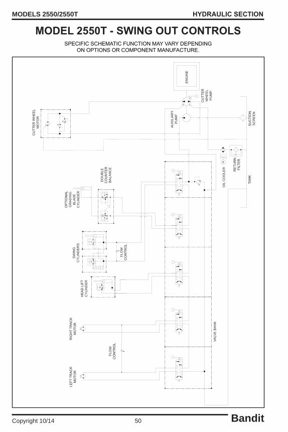
Bandit50Copyright 10/14
MODELS 2550/2550T
SPECIFICSCHEMATICFUNCTIONMAYVARYDEPENDINGONOPTIONSORCOMPONENTMANUFACTURE.
HYDRAULIC SECTION
MODEL 2550T - SWING OUT CONTROLS
SUCTION
SC
RE
EN
TANK
EN
GIN
E
OIL
CO
OLE
R RETU
RN
FILTER
VALV
E B
AN
K
HEADLIFT
CY
LIN
DE
R
LEFT
TRACK
MOTO
RS
WIN
G
CY
LIN
DE
RS
DO
UB
LE
COUNTE
R
BA
LAN
CE
FLO
W
CONTR
OL
CUTT
ERW
HEEL
MOTO
R
CUTT
ER
WH
EE
L P
UM
P
AU
XIL
IAR
Y P
UM
P
OPTIONAL
GR
AD
ING
B
LAD
E
CY
LIN
DE
R
RIGHTTR
ACK
MOTO
R
FLO
W
CONTR
OL

Bandit51Copyright 10/14
MODELS 2550/2550T
SPECIFICSCHEMATICFUNCTIONMAYVARYDEPENDINGONOPTIONSORCOMPONENTMANUFACTURE.
HYDRAULIC SECTION
MODEL 2550T - REMOTE CONTROL
)(
M
TANK
EN
GIN
E
OIL
CO
OLE
R
RETU
RN
FILTER
VALV
E B
AN
K
HEADLIFT
CY
LIN
DE
RS
WIN
G
CY
LIN
DE
RS
LEFT
TRACK
MOTO
R
CUTT
ERW
HEEL
MOTO
R
AU
XIL
IAR
Y P
UM
P
SUCTIONSCREEN
CUTT
ER
WH
EE
L P
UM
P
OPTIONAL
GR
AD
ING
B
LAD
E
CY
LIN
DE
RRIGHTTR
ACK
MOTO
R
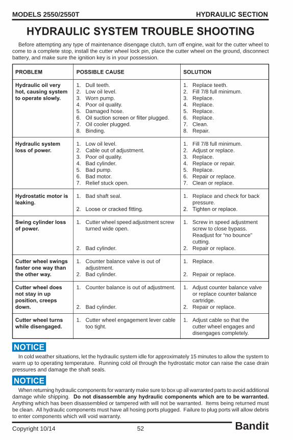
Bandit52Copyright 10/14
MODELS 2550/2550T HYDRAULIC SECTION
HYDRAULIC SYSTEM TROUBLE SHOOTING Before attempting any type of maintenance disengage clutch, turn off engine, wait for the cutter wheel to come to a complete stop, install the cutter wheel lock pin, place the cutter wheel on the ground, disconnect battery, and make sure the ignition key is in your possession.
PROBLEM
Hydraulic oil very hot, causing system to operate slowly.
Hydraulic system loss of power.
Hydrostatic motor is leaking.
Swing cylinder loss of power.
Cutter wheel swings faster one way than the other way.
Cutter wheel does not stay in up position, creeps down.
Cutter wheel turns while disengaged.
POSSIBLE CAUSE
1. Dull teeth.2. Low oil level.3. Worn pump.4. Poor oil quality.5. Damaged hose.6. Oilsuctionscreenorfilterplugged.7. Oil cooler plugged.8. Binding.
1. Low oil level.2. Cable out of adjustment.3. Poor oil quality.4. Bad cylinder.5. Bad pump.6. Bad motor.7. Relief stuck open.
1. Bad shaft seal.
2. Looseorcrackedfitting.
1. Cutter wheel speed adjustment screw turned wide open.
2. Bad cylinder.
1. Counter balance valve is out of adjustment.2. Bad cylinder.
1. Counter balance is out of adjustment.
2. Bad cylinder.
1. Cutter wheel engagement lever cable too tight.
SOLUTION
1. Replace teeth.2. Fill 7/8 full minimum.3. Replace.4. Replace.5. Replace.6. Replace.7. Clean.8. Repair.
1. Fill 7/8 full minimum.2. Adjust or replace.3. Replace.4. Replace or repair.5. Replace.6. Repair or replace.7. Clean or replace.
1. Replace and check for back pressure.2. Tightenorreplace.
1. Screw in speed adjustment screw to close bypass. Readjust for “no bounce” cutting.2. Repair or replace.
1. Replace.
2. Repair or replace.
1. Adjust counter balance valve or replace counter balance cartridge.2. Repair or replace.
1. Adjust cable so that the cutter wheel engages and disengages completely.
When returning hydraulic components for warranty make sure to box up all warranted parts to avoid additional damage while shipping. Do not disassemble any hydraulic components which are to be warranted. Anything which has been disassembled or tampered with will not be warranted. Items being returned must be clean. All hydraulic components must have all hosing ports plugged. Failure to plug ports will allow debris to enter components which will void warranty.
NOTICE
In cold weather situations, let the hydraulic system idle for approximately 15 minutes to allow the system to warm up to operating temperature. Running cold oil through the hydrostatic motor can raise the case drain pressures and damage the shaft seals.
NOTICE

Bandit53Copyright 10/14
MODELS 2550/2550T
DONOTOPERATEMACHINEWITHOUTAFULLSETOFTEETH.OPERATINGMACHINEWITHOUTAFULLSETOFTEETHCANCAUSEEXCESSIVEVIBRATIONANDPREMATUREBEARINGFAILURE.
Thereare twenty-four (24) teeth, twenty-four (24)tooth nuts, and sixteen (16) holders to a complete setonamodel2550or2550T. Twenty-four (24)teeth: eight (8) lead teeth (shorts) and sixteen (16) side teeth (longs). Sixteen (16) holders: eight (8) holders without locator pin and eight (8) holders with locator pin.
A locking pin is provided to hold the cutter wheel in position during tooth removal and reinstallation. Locking pin will only lock on outer teeth.
MODELS 2550/2550T
LeadTooth“Shorts”: 900-9909-96
SideTooth“Long”: 900-9906-05
Pocket without locator pin 900-9909-98
Pocket with locator pin: 900-9909-97
ToothNut: 900-9909-99
Useonlyoriginalequipmentmanufacturer’steeth.Theuseofanyotheraftermarketteethmaycausedamageor premature failure to the drive train.
CUTTER WHEEL SECTION
NEW RIVER “REVOLUTION” CUTTER WHEEL
Inspect teeth, nuts and pockets for damage and replace as required.
When replacing teeth, always replace new teeth across from each other (180°) in order to prevent vibration.
Replacement teeth must be carbide tipped and of like design as provided with the machine.
Tomakesurethecorrecttoothpatternisused,makesure a pocket with a locator pin is used on a station with a locator pin hole. Use the pockets without the locator pin on a station without the locator pin hole.
When replacing complete set of teeth, be sure to duplicate original factory tooth arrangement, with the carbidetipfacingthecutterwheelrotation.Typicallya 15/16” socket is required to change or torque the teeth.TorqueLeadTeethto200ft.-lbs.(271Nm)andSideTeethto125ft.-lbs.(169Nm).
TOOTH ARRANGEMENT
Lead Teeth
Side Teeth
DANGER!
NEVER USE HAND ON CUTTER WHEEL TO HOLD IN PLACE WHILE CHANGING TEETH. BE SURE TO REMOVE LOCKING PIN BEFORE OPERATING THE MACHINE.
NOTICEDo Not operate machine with extremely worn or broken teeth.

Bandit54Copyright 10/14
MODELS 2550/2550T
DONOTOPERATEMACHINEWITHOUTAFULLSETOFTEETH.OPERATINGMACHINEWITHOUTAFULLSETOFTEETHCANCAUSEEXCESSIVEVIBRATIONANDPREMATUREBEARINGFAILURE.
There are eighteen (18) teeth and pockets to acompletesetonamodel2550or2550T.Eighteen(18) teeth, six (6) straight pockets and twelve (12) angle pockets.
A locking pin is provided to hold the cutter wheel in position during tooth removal and reinstallation. Locking pin will only lock on outer teeth.
Inspect pockets, teeth and bolts for damage and replace as required.
When replacing pockets, always replace new pockets across from each other (180°) in order to prevent vibration.
Replacement teeth must be carbide tipped and of like design as provided with the machine.
Use anti-seize on threads to help prevent bolts from “freezing up” in cutter wheel pockets.
MODELS 2550/2550T
GreenToothWithNut: 900-9907-91
RedToothWithNut: 900-9907-92
Straight Pocket: 900-9907-87
Angle Pocket: 900-9907-86
Pocket Bolt: 900-9907-14
18GreenToothKit: 900-9908-24
Useonlyoriginalequipmentmanufacturer’steeth.Theuseofanyotheraftermarketteethmaycausedamageor premature failure to the drive train.
When replacing complete set of teeth, be sure to duplicate original factory tooth arrangement, with the carbide tip facing the cutter wheel rotation. Typically a 1/2” allen key socket is required tochangeortorquetheteeth.Torquepocketboltsto 125-150ft.-lbs.(169-203Nm).Torquetoothnutto31-43 ft.-lbs. (42-58 Nm).
All Outside Pockets require a straight pocket mountedoneachsideofthecutterwheel.Thereare three outside pockets on each side of the cutter wheel.
All Inside Pockets require an angle pocket mounted away from the cutter wheel.
CUTTER WHEEL SECTION
CUTTER WHEEL SECTION - GREEN TEETH
TOOTH ARRANGEMENT
DANGER!
NEVER USE HAND ON CUTTER WHEEL TO HOLD IN PLACE WHILE CHANGING TEETH. BE SURE TO REMOVE LOCKING PIN BEFORE OPERATING THE MACHINE.
NOTICEDo Not operate machine with extremely worn or broken teeth.

Bandit55Copyright 10/14
MODELS 2550/2550T
DONOTOPERATEMACHINEWITHOUTAFULLSETOFTEETH.OPERATINGMACHINEWITHOUTAFULLSETOFTEETHCANCAUSEEXCESSIVEVIBRATIONANDPREMATUREBEARINGFAILURE.
Thereareeighteen(18)teethandmountingblockstoacompletesetonamodel2550or2550T.Eighteen(18) teeth: six (6) straight teeth, six (6) right teeth, and six (6) left teeth. Eighteen (18) mounting blocks: nine (9) c’bored mounting blocks and nine (9) threaded mounting blocks.
A locking pin is provided to hold the cutter wheel in position during tooth removal and reinstallation. Locking pin will only lock on outer teeth.
Inspect pockets, teeth and bolts for damage and replace as required.
When replacing pockets, always replace new pockets across from each other (180°) in order to prevent vibration.
Replacement teeth must be carbide tipped and of like design as provided with the machine.
Use anti-seize on threads to help prevent bolts from “freezing up” in cutter wheel pockets.
MODELS 2550/2550T
TomahawkStraightTooth: 900-9903-82
TomahawkLeftTooth: 900-9903-83
TomahawkRightTooth: 900-9903-84
C’Bored Mounting Block: 900-9903-85
ThreadedMountingBlock: 900-9903-86
Pocket Bolt: 900-9903-80
Useonlyoriginalequipmentmanufacturer’steeth.Theuseofanyotheraftermarketteethmaycausedamageor premature failure to the drive train.
When replacing complete set of teeth, be sure to duplicate original factory tooth arrangement, with the carbide tip facing the cutter wheel rotation. Typically a 1/2” allen key socket is required tochangeor torquetheteeth. Torquetoothbolts to 125-150 ft.-lbs. (169-203 Nm).
All Outside Pockets require a straight pocket mountedoneachsideofthecutterwheel.Thereare three outside pockets on each side of the cutter wheel.
All Inside Pockets require an angle pocket mounted away from the cutter wheel.
CUTTER WHEEL SECTION
CUTTER WHEEL SECTION - TOMAHAWK
TOOTH ARRANGEMENT
DANGER!
NEVER USE HAND ON CUTTER WHEEL TO HOLD IN PLACE WHILE CHANGING TEETH. BE SURE TO REMOVE LOCKING PIN BEFORE OPERATING THE MACHINE.
NOTICEDo Not operate machine with extremely worn or broken teeth.

Bandit56Copyright 10/14
MODELS 2550/2550T ELECTRICAL SECTION
MACHINE HARNESS - GAS ENGINE & SWING OUT CONTROLS (203-8000-14)MACHINE HARNESS - DIESEL ENGINE & SWING OUT CONTROLS (203-8000-16)
SWING OUT HARNESS TO SELECTOR VALVE (203-8000-15)
MODEL 2550 SWING OUT CONTROLS
MODEL 2550 REMOTE CONTROLS
MACHINE HARNESS - DIESEL ENGINE & LOR REMOTE CONTROLS (203-8000-11)MACHINE HARNESS - DIESEL ENGINE & KAR-TECH / OMNEX REMOTE
CONTROLS (203-8000-13)MACHINE HARNESS - GAS ENGINE & LOR REMOTE CONTROLS (203-8000-10)
MACHINE HARNESS - GAS ENGINE & KAR-TECH / OMNEX REMOTE CONTROLS (203-8000-12)
DRIVE FORWARD VALVE HARNESS - REMOTE CONTROLS (991-8000-16)DRIVE FORWARD VALVE HARNESS - REMOTE CONTROLS (991-8000-17)
30 Amp Blade TypeFuse
12 Volt Sealed Relay
Swing Out Switch
30 Amp Blade TypeFuse
12 Volt Sealed Relay
12 Volt Sealed Relay
Remote/TetherToggleSwitch
Remote Link Light

Bandit57Copyright 10/14
MODELS 2550/2550T ELECTRICAL SECTION
MACHINE HARNESS - GAS ENGINE & SWING OUT CONTROLS (203-8000-14)MACHINE HARNESS - DIESEL ENGINE & SWING OUT CONTROLS (203-8000-16)
SWING OUT HARNESS TO SELECTOR VALVE (203-8000-15)
MODEL 2550T SWING OUT CONTROLS
MODEL 2550T REMOTE CONTROLS
MACHINE HARNESS - DIESEL ENGINE & KAR-TECH REMOTE CONTROLS (203-8000-26)
MACHINE HARNESS - GAS ENGINE & KAR-TECH REMOTE CONTROLS (xxx-xxxx-xx)
DRIVE FORWARD VALVE HARNESS - REMOTE CONTROLS (203-8000-28)DRIVE FORWARD VALVE HARNESS - REMOTE CONTROLS (203-8000-29)
30 Amp Blade TypeFuse
12 Volt Sealed Relay
Swing Out Switch
30 Amp Blade TypeFuse
12 Volt Sealed Relay
12 Volt Sealed Relay
Remote/TetherToggleSwitch
Remote Link Light

Bandit58Copyright 10/14
MODELS 2550/2550T
2550 MACHINE HARNESS - DIESEL ENGINE & KAR-TECH / OMNEX REMOTE CONTROLS (203-8000-13)
SPECIFICSCHEMATICFUNCTIONMAYVARYDEPENDINGONOPTIONSORCOMPONENTMANUFACTURE.
ELECTRICAL SECTION
BLK 16GA
2 C
AVIT
YM
ETRI
PAK
280
SERI
ES
FEM
ALE
RED 12GA
RED
12GA
TO
BATT
POS
30 A
MP
HE
LLA
SEAL
EDRE
LAY
CONN
ECTO
R
BLK
16GA
GREE
N FR
OM
TAC
HCU
T
PUR 18GA
SEE
NOTE
1
BA
TONG
UE
IN
11TO
NGU
E OU
T 9
WIT
H SU
PER
SWEE
P O
PTIO
N
TO
AU
TOFE
EDTA
CH -
1st
OU
TPU
T
15 A
MP
RED
16GA
SWIT
CH V
OLT
AGE
FUEL
SO
LENO
ID -
COM
MON
RED/
BLK
18GA
STEE
R RI
GHT
YEL
18G
A 6
SWIN
G RI
GHT
ORN
18G
A 1
2SW
ING
LEFT
OR
N/BL
K 18
GA
10
CUTT
ER D
OW
N B
LU/B
LK 1
8GA
7
DRIV
E FO
RWAR
D P
INK
18GA
1
DRIV
E RE
VERS
E P
INK/
BLK
18GA
2
SEE
NOTE
1
BLAD
E DO
WN
TAN
18G
A 4
SEE
NOTE
1
BLAD
E U
P T
AN/B
LK 1
8GA
3
STEE
R LE
FT
YEL/
BLK
18GA
5
SUPE
R SW
ING
INPU
T R
ED/W
HT/Y
EL 1
8GA
4RA
DIO
POW
ER
RED/
WHT
18G
A 6
LINK
LIG
HT
GRAY
18G
A 5
DTM
06-1
2SB
BLAC
K
DTM
06-1
2SA
GRAY
F T
AN 1
8GA
TO
NGU
E O
UT
/ BLA
DE D
OWN
K P
INK/
BLK
18GA
DR
IVE
REVE
RSE
L T
AN/B
LK 1
8GA
TO
NGU
E IN
/ BL
ADE
UP
P Y
EL/B
LK 1
8GA
STE
ER L
EFT
M
GRAY
18G
A L
INK
LIGH
T
B B
LU/B
LK 1
8GA
CU
TTER
DOW
N
J P
INK
18GA
DR
IVE
FORW
ARD
G O
RN/B
LK 1
8GA
SW
ING
LEFT
H O
RN 1
8GA
SW
ING
RIGH
T
N Y
EL 1
8GA
STE
ER R
IGHT
A R
ED 1
8GA
TET
HER
POW
ER
C B
LUE
18GA
CU
TTER
UP
TACH
HO
UR
MET
ERRE
D TO
RED
WHT
TO
WHT
BLK
TO B
LKGR
N TO
RED
/WHT
/YEL
WHT
IN H
ARNE
SS T
O P
NK B
EHIN
D KE
Y SW
ITCH
GROU
ND
BLAC
K 18
GA
3
CUTT
ER U
P B
LUE
18GA
8
FUEL
SO
LENO
ID -
NOR
MAL
LY O
PEN
SWIT
CH V
OLT
AGE
FROM
OIL
PRE
SSU
RE S
WIT
CH
GROU
ND
TO M
AGNE
TIC
PICK
-UP
FOR
OPTI
ONAL
SU
PER
SWEE
PTO
TAC
H OR
TACH
/HO
UR
M
ETER
TO
LIN
KLI
GHT
10 A
MP
RADI
O /
TETH
ERTO
GGLE
SW
ITCH
SING
LE P
OLE
SING
LE T
HROW
RED
16GA
CO
MM
ON P
OWER RE
D 16
GA
3 AM
P
WHT
18G
ABL
K 18
GARE
D 16
GARE
D 16
GA
WHT
18G
A
PUR
18GA
BLK 18GA
GRY 18GA
GRY
18GA
BLK
18GA
RED
18GA
TE
THER
POW
ER
RED/
WHT
18G
A R
ADIO
POW
ER
1/4"
TER
MIN
AL
RING
RED/
BLK
18GA
3 AM
P
3 AM
P
3 AM
P
3 AM
P
3 AM
P
3 AM
P
3 AM
P
3 AM
P
3 AM
P
3 AM
P
DT04
-6P
DT06
-6S
2 ORN/BLK 18GA
1 PINK/BLK 18GA
4 TAN/BLK 18GA5 YEL/BLK 18GA
3 BLU/BLK 18GA
5 YEL 18GA
2 ORN 18GA3 BLUE 18GA
4 TAN 18GA
1 PINK 18GA
HELL
A SE
ALED
RELA
Y CO
NNEC
TOR
HDP2
4-18
-14P
N

Bandit59Copyright 10/14
MODELS 2550/2550T
2550T MACHINE HARNESS - DIESEL ENGINE & KAR-TECH REMOTE CONTROLS (203-8000-26)
SPECIFICSCHEMATICFUNCTIONMAYVARYDEPENDINGONOPTIONSORCOMPONENTMANUFACTURE.
ELECTRICAL SECTION
DRIV
E RE
VERS
E P
INK/
BLK
18GA
2
DRIV
E FO
RWAR
D P
INK
18GA
1
CUTT
ER U
P B
LUE
18GA
8
CUTT
ER D
OW
N B
LU/B
LK 1
8GA
7
SWIN
G LE
FT
ORN/
BLK
18GA
10
SWIN
G RI
GHT
ORN
18G
A 1
2
STEE
R RI
GHT
YEL
18G
A 6
1 PINK 18GA
4 TAN 18GA
3 BLUE 18GA2 ORN 18GA
5 YEL 18GA
3 BLU/BLK 18GA
5 YEL/BLK 18GA4 TAN/BLK 18GA
1 PINK/BLK 18GA
2 ORN/BLK 18GA
3 AM
P
3 AM
P
3 AM
P
3 AM
P
3 AM
P
3 AM
P
3 AM
P
3 AM
P
3 AM
P
3 AM
P
RED/
BLK
18GA
G
ROU
ND1/
4" T
ERM
INAL
RI
NG
3 RE
D/W
HT 1
8GA
RAD
IO P
OWER
1 RE
D 18
GA
TET
HER
POW
ER
BLK
18GA
GRY
18GA
GRY 18GA
BLK 18GA
PUR
18GA
WHT
18G
A
RED
16GA
RED
16GA
BLK
14GA
B
BLK 14GA
A RE
D 14
GA
3 AM
P
DTM
06-1
2SA
GRAY
DTM
06-1
2SB
BLAC
KHD
34-1
8-14
PE
DT06
-6S
-E0
03
DT04
-6P
-E0
03
TO H
YD. C
OOLI
NGFA
N HE
LLA
SEAL
EDRE
LAY
DT04
-4P
-E0
03
TO RAD
IORE
CEIV
ER
HYD.
OU
TPU
TS T
O V
ALVE
TO TETH
ER
900-
2917
-45
TO E
NGIN
E KI
LLHE
LLA
SEAL
EDRE
LAY
900-
2917
-45
TO H
YD.
COO
LING
FAN
900-
2923
-28
3 WHT/RED 18GA
4 BLK 18GA GND
BLK
18GA
WHT
18G
A
3 AM
P
GRY
18GA
2 RE
D 16
GA
COM
MON
POW
ER
RADI
O /
TETH
ERTO
GGLE
SW
ITCH
SING
LE P
OLE
SING
LE T
HROW
10 A
MP
TO
LIN
KLI
GHT
TO T
ACH
ORTA
CH/H
OUR
M
ETER
TO M
AGNE
TIC
PICK
-UP
FOR
OPTI
ONAL
SU
PER
SWEE
P
GROU
ND
SWIT
CH V
OLTA
GE F
ROM
OIL
PRES
SURE
SWI
TCH
FUEL
SOL
ENOI
D -
NORM
ALLY
OPE
N
RED/
BLK
18GA
FUEL
SOL
ENOI
D -
COM
MON
SWIT
CH V
OLTA
GERE
D 16
GA15
AM
P
T
O A
UTO
FEED
TACH
- 1
st O
UTP
UT
WIT
H SU
PER
SWEE
P OP
TION
A B
PUR 18GA
CUT
GREE
N FR
OM T
ACH
BLK
16GA
30 A
MP
TO
BATT
POS
RED
12GA
RED 12GA
BLK 16GA
TACH
HO
UR
MET
ERRE
D TO
RED
WHT
TO
WHT
BLK
TO B
LKGR
N TO
RED
/WHT
/YEL
WHT
IN H
ARNE
SS T
O P
NK B
EHIN
D KE
Y SW
ITCH
C B
LUE
18GA
CU
TTER
UP
A
RED
18GA
T
ETHE
R PO
WER
N Y
EL 1
8GA
STE
ER R
IGHT
H O
RN 1
8GA
SW
ING
RIGH
TG
ORN
/BLK
18G
A S
WIN
G LE
FT
J P
INK
18GA
DR
IVE
FORW
ARD
B B
LU/B
LK 1
8GA
CU
TTER
DOW
N
M
GRAY
18G
A E
NGIN
E RU
N
P Y
EL/B
LK 1
8GA
STE
ER L
EFT
L T
AN/B
LK 1
8GA
BLA
DE U
P
K P
INK/
BLK
18GA
DR
IVE
REVE
RSE
F T
AN 1
8GA
BLA
DE D
OW
N
ENGI
NE R
UN
GRA
Y 18
GA
5RA
DIO
PO
WER
R
ED/W
HT 1
8GA
6SU
PER
SWIN
G IN
PUT
RED
/WHT
/YEL
18G
A 4
GRO
UND
BL
ACK
18GA
3
STEE
R LE
FT
YEL
/BLK
18G
A 5
BLAD
E U
P T
AN/B
LK 1
8GA
3BL
ADE
DOW
N T
AN 1
8GA
4
DUM
P VA
LVE
OUTP
UT
WHT
/RED
18G
A 9
1 WHT/RED 18GA
ENGI
NE C
ONN
ECTI
ON
2 BLK 18GA GND
D W
HT/R
ED 1
8GA
DUM
P
RED
14GA
RED
16GA
87
8586
87A
30
87
8586
87A
30

Bandit60Copyright 10/14
MODELS 2550/2550T
2550 MACHINE HARNESS - GAS ENGINE & LOR REMOTE CONTROLS (203-8000-10)
SPECIFICSCHEMATICFUNCTIONMAYVARYDEPENDINGONOPTIONSORCOMPONENTMANUFACTURE.
ELECTRICAL SECTION
15 A
MP
RED
16GA
SWIT
CH V
OLT
AGE
TO O
IL S
HUTD
OWN
SWIT
CH V
OLT
AGE
FROM
OIL
PRE
SSU
RE S
WIT
CH
GRO
UND
TO M
AGNE
TIC
PICK
-UP
FOR
OPT
IONA
L SU
PER
SWEE
PTO
TAC
H OR
TACH
/HOU
R
MET
ER
TO
LIN
KLI
GHT
10 A
MP
RADI
O /
TETH
ERTO
GGLE
SW
ITCH
SING
LE P
OLE
SING
LE T
HROW
RED
16GA
CO
MM
ON P
OWER RE
D 16
GA
3 AM
P
WHT
18G
ABL
K 18
GARE
D 16
GARE
D 16
GABL
K 18
GAW
HT 1
8GA
PUR
18GA
BLK 18GA
GRY 18GA
GRY
18GA
BLK
18GA
RED
18GA
TE
THER
POW
ER
RED/
WHT
18G
A R
ADIO
POW
ER
1/4"
TER
MIN
AL
RING
3 AM
P
3 AM
P
3 AM
P
3 AM
P
3 AM
P
3 AM
P
3 AM
P
3 AM
P
3 AM
P
3 AM
P
DT04
-6P
DT06
-6S
2 ORN/BLK 18GA
1 PINK/BLK 18GA
4 TAN/BLK 18GA5 YEL/BLK 18GA
3 BLU/BLK 18GA
5 YEL 18GA
2 ORN 18GA3 BLUE 18GA
4 TAN 18GA
GRO
UND
BL
ACK
18GA
12
POW
ER
RED
18G
A
1
POW
ER
RED
18G
A
1
BLK 16GA
2 C
AVIT
YM
ETRI
PAK
280
SERI
ES F
EMAL
E
RED 12GA
RED
12GA
TO
BATT
POS
30 A
MP
HE
LLA
SEAL
EDRE
LAY
CONN
ECTO
R
BLK
16GA
GREE
N FR
OM
TAC
HCU
T
PUR 18GA
SEE
NOTE
1
BA
TONG
UE
IN
8TO
NGU
E O
UT
5
WIT
H SU
PER
SWEE
P OP
TION
TO
AU
TOFE
EDTA
CH -
1st
OU
TPU
T
1 PINK 18GA
HELL
A SE
ALED
RELA
Y CO
NNEC
TOR
HDP2
4-18
-14P
N
STEE
R RI
GHT
YEL
18G
A 6
SWIN
G RI
GHT
ORN
18G
A 9
SWIN
G LE
FT
ORN/
BLK
18GA
4
CUTT
ER D
OW
N B
LU/B
LK 1
8GA
3CU
TTER
UP
BLU
E 18
GA
10
DRIV
E FO
RWAR
D P
INK
18GA
4
DRIV
E RE
VERS
E P
INK/
BLK
18GA
9
SEE
NOTE
1
BLAD
E DO
WN
TAN
18G
A 2
SEE
NOTE
1
BLAD
E U
P T
AN/B
LK 1
8GA
11
STEE
R LE
FT
YEL/
BLK
18GA
5
GRO
UND
BL
ACK
18GA
12
SUPE
R SW
ING
INPU
T R
ED/W
HT/Y
EL 1
8GA
7
RADI
O P
OWER
RE
D/W
HT 1
8GA
6EN
GINE
RU
N G
RAY
18GA
3
DTM
06-1
2SB
BLAC
K
DTM
06-1
2SA
GRAY
F T
AN 1
8GA
TO
NGU
E OU
T / B
LADE
DOW
N
K P
INK/
BLK
18GA
DR
IVE
REVE
RSE
L T
AN/B
LK 1
8GA
TO
NGU
E IN
/ BL
ADE
UP
P Y
EL/B
LK 1
8GA
STE
ER L
EFT
M
GRAY
18G
A L
INK
LIGH
T
B B
LU/B
LK 1
8GA
CU
TTER
DOW
N
J P
INK
18GA
DR
IVE
FORW
ARD
G O
RN/B
LK 1
8GA
SW
ING
LEFT
H O
RN 1
8GA
SW
ING
RIGH
T
N Y
EL 1
8GA
STE
ER R
IGHT
A R
ED 1
8GA
TET
HER
POW
ER
C B
LUE
18GA
CU
TTER
UP
TACH
HOU
R M
ETER
RED
TO R
EDW
HT T
O W
HTBL
K TO
BLK
GRN
TO R
ED/W
HT/Y
ELW
HT IN
HAR
NESS
TO
PNK
BEHI
ND K
EY S
WIT
CH
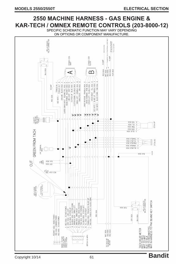
Bandit61Copyright 10/14
MODELS 2550/2550T
2550 MACHINE HARNESS - GAS ENGINE & KAR-TECH / OMNEX REMOTE CONTROLS (203-8000-12)
SPECIFICSCHEMATICFUNCTIONMAYVARYDEPENDINGONOPTIONSORCOMPONENTMANUFACTURE.
ELECTRICAL SECTION
BLK 16GA
2 C
AVIT
YM
ETRI
PAK
280
SERI
ES F
EMAL
E
RED 12GA
RED
12GA
TO
BATT
POS
30 A
MP
HE
LLA
SEAL
EDRE
LAY
CONN
ECTO
R
BLK
16GA
GREE
N FR
OM
TAC
HCU
T
PUR 18GASE
E NO
TE 1
BA
TONG
UE
IN
11TO
NGU
E OU
T 9
WIT
H SU
PER
SWEE
P O
PTIO
N
TO
AU
TOFE
EDTA
CH -
1st
OU
TPU
T
15 A
MP
RED
16GA
SWIT
CH V
OLTA
GE
TO O
IL S
HUTD
OWN
SWIT
CH V
OLT
AGE
FROM
OIL
PRE
SSU
RE S
WIT
CH
GRO
UND
TO M
AGNE
TIC
PICK
-UP
FOR
OPTI
ONAL
SU
PER
SWEE
PTO
TAC
H OR
TACH
/HOU
R
MET
ER
TO
LIN
KLI
GHT
10 A
MP
RADI
O / T
ETHE
RTO
GGLE
SW
ITCH
SING
LE P
OLE
SING
LE T
HROW
RED
16GA
CO
MM
ON
POW
ER RED
16GA
3 AM
P
WHT
18G
ABL
K 18
GARE
D 16
GARE
D 16
GABL
K 18
GAW
HT 1
8GA
PUR
18GA
BLK 18GA
GRY 18GA
GRY
18GA
BLK
18GA
RED
18GA
TE
THER
POW
ER
RED/
WHT
18G
A R
ADIO
POW
ER
1/4"
TER
MIN
AL
RING
3 AM
P
3 AM
P
3 AM
P
3 AM
P
3 AM
P
3 AM
P
3 AM
P
3 AM
P
3 AM
P
3 AM
P
DT04
-6P
DT06
-6S
2 ORN/BLK 18GA
1 PINK/BLK 18GA
4 TAN/BLK 18GA5 YEL/BLK 18GA
3 BLU/BLK 18GA
5 YEL 18GA
2 ORN 18GA3 BLUE 18GA
4 TAN 18GA
1 PINK 18GA
HE
LLA
SEAL
EDRE
LAY
CONN
ECTO
R
HDP2
4-18
-14P
N
STEE
R RI
GHT
YEL
18G
A 6
SWIN
G RI
GHT
ORN
18G
A 1
2SW
ING
LEFT
OR
N/BL
K 18
GA
10
CUTT
ER D
OW
N B
LU/B
LK 1
8GA
7
DRIV
E FO
RWAR
D P
INK
18GA
1
DRIV
E RE
VERS
E P
INK/
BLK
18GA
2
SEE
NOTE
1
BLAD
E DO
WN
TAN
18G
A 4
SEE
NOTE
1
BLAD
E U
P T
AN/B
LK 1
8GA
3
STEE
R LE
FT
YEL/
BLK
18GA
5
SUPE
R SW
ING
INPU
T R
ED/W
HT/Y
EL 1
8GA
4RA
DIO
POW
ER
RED/
WHT
18G
A 6
LINK
LIG
HT
GRAY
18G
A 5
DTM
06-1
2SB
BLAC
K
DTM
06-1
2SA
GRAY
F T
AN 1
8GA
TON
GUE
OUT
/ BLA
DE D
OWN
K P
INK/
BLK
18GA
DR
IVE
REVE
RSE
L T
AN/B
LK 1
8GA
TON
GUE
IN /
BLAD
E U
P
P Y
EL/B
LK 1
8GA
STE
ER L
EFT
M
GRAY
18G
A L
INK
LIGH
T
B B
LU/B
LK 1
8GA
CU
TTER
DOW
N
J P
INK
18GA
DR
IVE
FORW
ARD
G O
RN/B
LK 1
8GA
SW
ING
LEFT
H O
RN 1
8GA
SW
ING
RIGH
T
N Y
EL 1
8GA
STE
ER R
IGHT
A R
ED 1
8GA
TET
HER
POW
ER
C B
LUE
18GA
CU
TTER
UP
TACH
HO
UR
MET
ERRE
D TO
RED
WHT
TO
WHT
BLK
TO B
LKGR
N TO
RED
/WHT
/YEL
WHT
IN H
ARNE
SS T
O P
NK B
EHIN
D KE
Y SW
ITCH
CUTT
ER U
P B
LUE
18GA
8
GRO
UND
BL
ACK
18GA
3

Bandit62Copyright 10/14
MODELS 2550/2550T ELECTRICAL SECTION
MO
LDED
HER
SHM
AN C
ONNE
CTOR
MO
LDED
HER
SHM
AN C
ONNE
CTOR
MO
LDED
HER
SHM
AN C
ONNE
CTOR
MO
LDED
HER
SHM
AN C
ONNE
CTOR
MO
LDED
HER
SHM
AN C
ONNE
CTOR
DT06
-6S
1/4"
TER
MIN
AL R
ING
BLU
E
BRO
WN
BLU
E
BRO
WN
BLU
E
BRO
WN
BLU
E
BRO
WN
BLU
E
BRO
WN
BLACK 16GA GROUND
TOU
NGU
E O
UT
/ BLA
DE D
OWN
CUTT
ER U
P
SWIN
G RI
GHT
DRIV
E FO
RWAR
D
2
BRO
WN
SW
ING
RIGH
T
1
BRO
WN
DR
IVE
FORW
ARD
4
BRO
WN
TO
NGU
E O
UT
/ BLA
DE D
OWN
3
BRO
WN
CU
TTER
UP
5
BRO
WN
ST
EER
RIGH
T
STEE
R RI
GHT
DRIVE FORWARD VALVE HARNESSMODEL 2550 (991-8000-16)
SPECIFICSCHEMATICFUNCTIONMAYVARYDEPENDINGONOPTIONSORCOMPONENTMANUFACTURE.

Bandit63Copyright 10/14
MODELS 2550/2550T ELECTRICAL SECTION
MO
LDED
HER
SHM
AN C
ONNE
CTOR
MO
LDED
HER
SHM
AN C
ONNE
CTOR
MO
LDED
HER
SHM
AN C
ONNE
CTOR
MO
LDED
HER
SHM
AN C
ONNE
CTOR
MO
LDED
HER
SHM
AN C
ONNE
CTOR
DT04
-6P
1/4"
TER
MIN
AL R
ING
BLU
E
BROW
N
BLU
E
BROW
N
BLU
E
BROW
N
BLU
E
BROW
N
BLU
E
BROW
N
BLACK 16GA GROUND
STEE
R LE
FT
TOU
NGU
E IN
/ BL
ADE
UP
CUTT
ER D
OWN
SWIN
G LE
FT
DRIV
E RE
VERS
E
2 B
ROW
N S
WIN
G LE
FT
1 B
ROW
N D
RIVE
REV
ERSE
4 B
ROW
N T
ONGU
E IN
/ BL
ADE
UP
5 B
ROW
N S
TEER
LEF
T
3 B
ROW
N C
UTT
ER D
OWN
DRIVE REVERSE VALVE HARNESSMODEL 2550 (991-8000-17)
SPECIFICSCHEMATICFUNCTIONMAYVARYDEPENDINGONOPTIONSORCOMPONENTMANUFACTURE.

Bandit64Copyright 10/14
MODELS 2550/2550T ELECTRICAL SECTION
DRIVE FORWARD VALVE HARNESSMODEL 2550T (203-8000-28)
SPECIFICSCHEMATICFUNCTIONMAYVARYDEPENDINGONOPTIONSORCOMPONENTMANUFACTURE.
3 B
ROW
N C
UTT
ER U
P
5 B
ROW
N S
TEER
RIG
HT
4 B
ROW
N T
ONGU
E OU
T / B
LADE
DOW
N
1 B
ROW
N D
RIVE
FOR
WAR
D
2 B
ROW
N S
WIN
G RI
GHT
LEFT
TRA
CK F
ORW
ARD
SWIN
G RI
GHT
CUTT
ER U
P
TOU
NGU
E O
UT
/ BLA
DE D
OWN
RIGH
T TR
ACK
FOW
ARD
BLACK 16GA GROUND
BRO
WN
BLU
E
BRO
WN
BLU
E
BRO
WN
BLU
E
BRO
WN
BLU
E
BRO
WN
BLU
E
1/4"
TER
MIN
AL R
ING
DT06
-6S
MOL
DED
HERS
HMAN
CON
NECT
OR
MOL
DED
HERS
HMAN
CON
NECT
OR
MOL
DED
HERS
HMAN
CON
NECT
OR
MOL
DED
HERS
HMAN
CON
NECT
OR
MOL
DED
HERS
HMAN
CON
NECT
OR
A
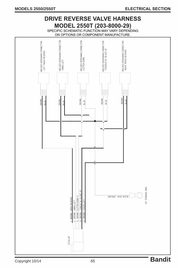
Bandit65Copyright 10/14
MODELS 2550/2550T ELECTRICAL SECTION
DRIVE REVERSE VALVE HARNESSMODEL 2550T (203-8000-29)
SPECIFICSCHEMATICFUNCTIONMAYVARYDEPENDINGONOPTIONSORCOMPONENTMANUFACTURE.
3 B
ROW
N C
UTT
ER D
OWN
5 B
ROW
N S
TEER
LEF
T
4 B
ROW
N T
ONGU
E IN
/ BL
ADE
UP
1 B
ROW
N D
RIVE
REV
ERSE
2 B
ROW
N S
WIN
G LE
FT
LEFT
TRA
CK R
EVER
SE
SWIN
G LE
FT
CUTT
ER D
OWN
TOU
NGU
E IN
/ BL
ADE
UP
RIGH
T TR
ACK
REVE
RSE
BLACK 16GA GROUND
BRO
WN
BLU
E
BRO
WN
BLU
E
BRO
WN
BLU
E
BRO
WN
BLU
E
BRO
WN
BLU
E
1/4"
TER
MIN
AL R
ING
DT04
-6P
MOL
DED
HERS
HMAN
CON
NECT
OR
MOL
DED
HERS
HMAN
CON
NECT
OR
MOL
DED
HERS
HMAN
CON
NECT
OR
MOL
DED
HERS
HMAN
CON
NECT
OR
MOL
DED
HERS
HMAN
CON
NECT
OR
A
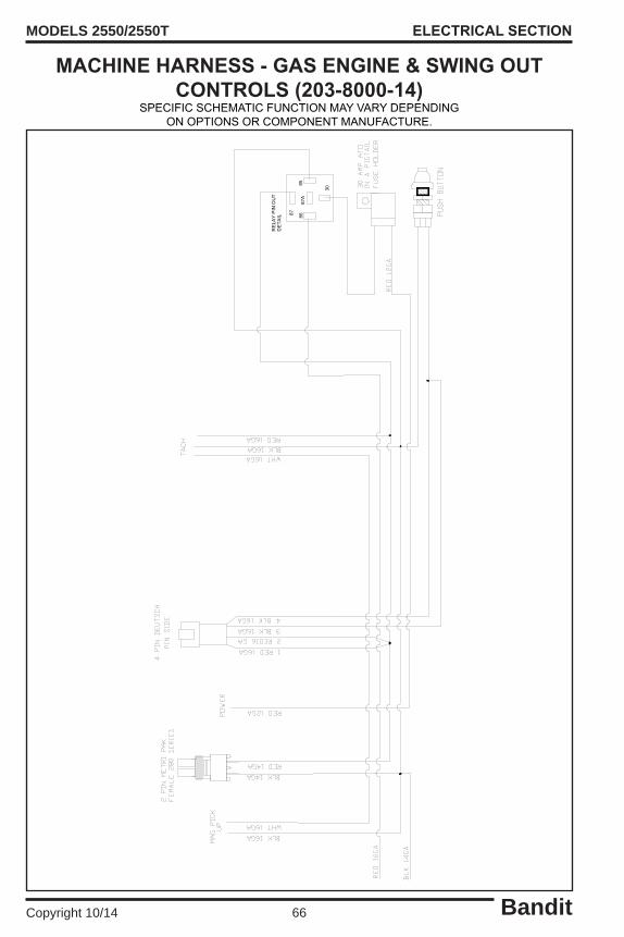
Bandit66Copyright 10/14
MODELS 2550/2550T
MACHINE HARNESS - GAS ENGINE & SWING OUT CONTROLS (203-8000-14)
SPECIFICSCHEMATICFUNCTIONMAYVARYDEPENDINGONOPTIONSORCOMPONENTMANUFACTURE.
ELECTRICAL SECTION
87
87A
8685
30
RELA
YPINOUT
DETA
IL

Bandit67Copyright 10/14
MODELS 2550/2550T
MACHINE HARNESS - DIESEL ENGINE & SWING OUT CONTROLS (203-8000-16)
SPECIFICSCHEMATICFUNCTIONMAYVARYDEPENDINGONOPTIONSORCOMPONENTMANUFACTURE.
ELECTRICAL SECTION
87
87A
8685
30
REL
AYPINOUT
DETA
IL

Bandit68Copyright 10/14
MODELS 2550/2550T
1. Engine: Followoriginalequipmentmanufacturer’srequirementsforbothchangingoilsandfilters,refertoenginemanualspecifications.
2. Engine Coolant:Refertoenginemanufacturer’smanualspecifications.
3. Hydraulic Reservoir Tank: Completelychangehydraulicoil,suctionscreen(s),andflushthetankannually.Changehydraulicoilfilter(s)AFTERFIRST10HOURSOFOPERATION.Thenchangehydraulicoilfilter(s)every 3 months or 400 hours thereafter. Maintain hydraulic oil level 7/8 full. See hydraulic oil requirements below. Check hydraulic oil level in tank daily.
4. High Pressure & Charge Filters: ChangehighpressureandchargefiltersAFTERFIRST 10 HOURS OFOPERATION.Thenchangehighpressureandchargefilterevery3monthsor400hoursthereafter.
5. Hydraulic Fluid Requirements:Seepages41-42forhydraulicfluidrequirements.
6. Cutter Wheel Arm Pivot Bushings: Grease cutter wheel arm up and down pivot bushings daily with one (1) to two (2) shots of EP-2 Lithium type grease. Wipe off excess grease. Excessive grease will attract dirt.
7. Swing Pivot Assembly Bushings: Grease top and bottom swing pivot assembly bushings weekly with one (1) to two (2) shots of EP-2 Lithium type grease. Wipe off excess grease. Excessive grease will attract dirt.
8. Steering Axle Pivot Bushings (Model 2550 Only): Grease steering axle pivot bushings weekly with one (1) to two (2) shots of EP-2 Lithium type grease. Wipe off excess grease. Excessive grease will attract dirt.
9. Steering Bushings (Model 2550 Only): Grease steering bushings weekly with one (1) to two (2) shots of EP-2 Lithium type grease. Wipe off excess grease. Excessive grease will attract dirt.
10. Cylinder Lug Pin Bushings: Grease cylinder lug pin bushings weekly with one (1) to two (2) shots of EP-2 Lithium type grease. Wipe off excess grease. Excessive grease will attract dirt.
11. Swing Out Pivot Bushings: Grease swing out pivot bushings weekly with one (1) to two (2) shots of EP-2 Lithium type grease. Wipe off excess grease. Excessive grease will attract dirt.
12. Steel Friction Areas: Lubricate all steel friction areas including, but not limited to pivoting, hinged, sliding, and rotating areas weekly. (i.e. cutter wheel guard, control box doors, swing out pivot, etc.).
13. Grading Blade Bushings (if equipped): Grease grading blade bushings monthly with one (1) to two (2) shots of EP-2 Lithium type grease. Wipe off excess grease. Excessive grease will attract dirt.
14. Cutter Wheel Engagement Lever Cable: Lubricate the inner cable and cable ends with a cable lube or SAE 10W/30 oil every month. Replace cutter wheel engagement lever cable if it doesn’t operate smoothly.
15. Wheel Hub Bearings (Model 2550 2 Wheel Drive Only): Inspect and clean the wheel hub bearings, cups, and seals. Replace seals if ever removed. Grease wheel bearings with an EP-2 Lithium type grease. Remove rubber plug and pump grease into E-Z Lube zerk until all of old grease is pumped out of dust cap. Wipe off excess grease and replace rubber plug. Excessive grease will attract dirt.
LUBRICATION & COOLANT
LUBRICATION & COOLANT

Bandit69Copyright 10/14
MODELS 2550/2550T
Depending on what replacement parts you are ordering the following information will be needed:
GRINDER COMPONENTSSerial Number
Model Number of Grinder
ENGINE COMPONENTSBrand
Engine Serial NumberEngine Spec. Number
Bandit Industries Inc. reserves the right to make changes in models, size, design, installations andapplicationsonanypartwithoutnotification.
All nuts, bolts, washers, and many other components can be ordered by physical description.
When ordering any replacement parts you should have the serial number (S/N) and model of the machine to ensure that you receive the correct replacement part. See page 6 for typical serial number & work order number locations.
Some of the components shown in this section are for optional equipment and may not apply to every machine.
REPLACEMENT PARTS
REPLACEMENT PARTS SECTION
NOTICE
NOTICE
NOTICE
NOTICE

Bandit70Copyright 10/14
MODELS 2550/2550T
Parts may not be exactly as shown.NOTICE
FRAME COMPONENTS
MODEL 2550T

Bandit71Copyright 10/14
MODELS 2550/2550T
LOCATION PARTNUMBER DESCRIPTION
1 a. 900-5911-33 RubberTrack-NoTread b. 900-5913-05 RubberTrack-WithTread2. 900-5911-26 Small Roller3. 900-5911-69 Idler Roller4. 400-3001-24 Idler End Retainer5. 400-2000-07 Front Idler Mount Assembly6 a. 402-2000-03 TrackFrameAssembly-RoadSide b. 402-1000-03 TrackAssembly-RoadSide(Includes1-15)7. 900-4917-27 TensionSpring8. 400-1000-04 SpringTensionTab9. 400-1000-08 TrackAdjusterBoltAssembly10. 402-3000-13 TrackAdjusterBoltRetainer11. 402-3000-10 Drive Hub12. 402-3000-09 Drive Sprocket13. 900-3959-99 Hydraulic Motor With Brake14. 402-3000-12 TrackMotorDrawRing15. 402-3000-14 TopTrackGuide16 a. 402-2000-04 TrackFrameAssembly-CurbSide b. 402-1000-04 TrackAssembly-CurbSide(Includes1-5&7-15)17. 203-2000-80 TrackSupport18. 203-3003-06 Swing Cylinder Chip Curtain19. 203-3003-12 Strap for Swing Cylinder Chip Curtain20. 900-1902-42 Split Bushing - 1-1/4” OD x 1” ID x 1”21. 900-1916-28 Split Bushing - 1” OD x 3/4” ID x 1/2”22. 203-2000-84 Swing Out Bolt-On Mount23. 900-7901-71 Plastic Battery Liner Box24. 900-6900-01 530 CCA Battery25 a. 900-3959-57 Cutter Wheel Pump Mount - Kohler Engines Only b. 900-3959-56 Cutter Wheel Pump Mount - Briggs & Stratton (Vanguard) Engines Only c. 900-3959-75 Pump Mount Access Cover26. 900-3956-12 Cutter Wheel Pump Coupler - Pump Side - Gasoline Engines Only27. 900-3956-00 Cutter Wheel Pump Coupler Spider - Gasoline Engines Only28. 900-1916-35 Cutter Wheel Pump Coupler - Engine Side - Gasoline Engines Only29. 900-6916-26 Engine Isolator30 a. 900-3956-86 Auxiliary Pump b. 900-3956-87 Auxiliary Pump With 4WD Option31. 900-3955-97 Cutter Wheel Hydraulic Pump32. 203-2000-49 Pump Engagement Lever33 a. 900-3937-80 Engine Oil Drain Hose b. 900-3936-41 Cap for Engine Oil Drain Hose34. 203-2000-53 Manual Holder Mount35. 900-9910-28 Manual Holder36. 203-2000-51 Bumper Assembly37. 203-2000-71 Oil Cooler Cover38. 900-3952-11 Oil Cooler39. 203-2000-40 Oil Cooler Mount & Assembly (Includes 37-40) 40. 904-0007-30 Oil Cooler Screen
FRAME COMPONENTS
Nuts, bolts, washers, and all other components can be ordered by physical description.NOTICE
MODEL 2550T

Bandit72Copyright 10/14
MODELS 2550/2550T
Parts may not be exactly as shown.NOTICE
FRAME COMPONENTS
MODEL 2550

Bandit73Copyright 10/14
MODELS 2550/2550T
LOCATION PARTNUMBER DESCRIPTION
1 a. 900-5909-22 18”x8.50”-10”Tire&White,5BoltRim(SpecifyLeftorRight) b. 900-5909-20 18”x8.50”-10”TireOnly c. 900-5909-21 10” x 6” White, 5 Bolt Rim Only2. 900-4913-38 1”-8NC x 5 1/2” Hex Head Bolt3 a. 900-4900-79 1“ Flat Washer b. 900-4908-99 1” Lock Washer (Not Shown)4 a. 991-2000-81 Dual Wheel Spacer b. 991-1000-60 Dual Wheel Spacer Kit - Includes 2, 3, 4, 5, & 65. 900-4914-00 1/2”-20NF Lug Nut6. 991-2000-80 Dual Wheel Hub7. 900-3938-50 1”-20UNEF Hex Slotted Nut8 a. 991-1000-61 Wheel Hub Assembly b. 900-5905-97 1/2”-20NF Stud Only9. 900-3947-20 Hydraulic Motor With Brake10. 203-3003-06 Swing Cylinder Chip Curtain11. 203-3003-12 Strap for Swing Cylinder Chip Curtain12. 900-1902-42 Split Bushing - 1-1/4” OD x 1” ID x 1”13. 900-1916-28 Split Bushing - 1” OD x 3/4” ID x 1/2”14. 203-3001-38 Frame Chip Pan Curtain15. 203-3001-40 Long Chip Pan Strap16. 203-3001-42 Short Chip Pan Strap17. 900-7901-71 Plastic Battery Liner Box18. 900-6900-01 530 CCA Battery19 a. 900-3959-57 Cutter Wheel Pump Mount - Kohler Engines Only b. 900-3959-56 Cutter Wheel Pump Mount - Briggs & Stratton (Vanguard) Engines Only c. 900-3959-75 Pump Mount Access Cover20. 900-3956-12 Cutter Wheel Pump Coupler - Pump Side - Gasoline Engines Only21. 900-3956-00 Cutter Wheel Pump Coupler Spider - Gasoline Engines Only22. 900-1916-35 Cutter Wheel Pump Coupler - Engine Side - Gasoline Engines Only23. 900-6916-26 Engine Isolator24 a. 900-3956-86 Auxiliary Pump b. 900-3956-87 Auxiliary Pump With 4WD Option25. 900-3955-97 Cutter Wheel Hydraulic Pump26. 203-2000-49 Pump Engagement Lever27 a. 900-3937-80 Engine Oil Drain Hose b. 900-3936-41 Cap for Engine Oil Drain Hose28. 203-2000-53 Manual Holder Mount29. 900-9910-28 Manual Holder30 a. 203-2000-60 Bumper Assembly for Gasoline Engine (Weighted) b. 203-2000-51 Bumper Assembly (Not Shown)31. 203-2000-71 Oil Cooler Cover32. 900-3952-11 Oil Cooler33. 203-2000-40 Oil Cooler Mount & Assembly (Includes 31-34) 34. 904-0007-30 Oil Cooler Screen
FRAME COMPONENTS
Nuts, bolts, washers, and all other components can be ordered by physical description.NOTICE
MODEL 2550

Bandit74Copyright 10/14
MODELS 2550/2550T STEERING COMPONENTS
Parts may not be exactly as shown.NOTICE
FOUR WHEEL DRIVE OPTION
MODEL 2550

Bandit75Copyright 10/14
MODELS 2550/2550T
LOCATION PARTNUMBER DESCRIPTION
1. 203-2000-03 Pivot Steering Mount2. 900-1908-37 Split Bushing - 1-3/4” OD x 1-1/2” ID x 1-1/2”3. 900-1902-50 Split Bushing - 1-1/4” OD x 1” ID x 1-1/2”4. 203-2000-08 Steering Pivot Pin5 a. 203-3000-79 Pin Retainer Washer b. 900-4900-13 3/8”-16NC x 1” Hex Head Bolt c. 900-4906-62 3/8” Lock Washer6. 203-1000-03 SteeringTieRodAssembly7. 900-4900-80 1”-8NC Nylon Insert Hex Lock Nut8. 900-4904-46 1” Mill Carb Washer9. 900-4913-38 1”-8NCx5-1/2”HexHeadBolt(1-1/4”ofThread)-Special10. 203-2000-05 Steering Mount - Right (Curb) Side11 a. 203-2000-06 Spindle Mount b. 900-5905-37 Hub Assembly c. 021-041-01 Grease Cap For Hub (Not Shown) d. 085-001-00 Rubber Cap For Grease Cap (Not Shown) e. 031-031-02 Inner & Outer Bearing For Hub (Not Shown) f. 031-031-01 Inner & Outer Bearing Cup For Hub (Not Shown) g. 010-060-00 Inner & Outer Seal For Hub (Not Shown) h. 900-5905-97 1/2”-20NF Stud Only12 a. 900-5909-22 18”x8.50”-10”Tire&White,5BoltRim(SpecifyLeftorRight) b. 900-5909-20 18”x8.50”-10”TireOnly c. 900-5909-21 10” x 6” White, 5 Bolt Rim Only13. 900-4914-00 1/2”-20NF Lug Nut14. 203-2000-04 Steering Mount - Left (Road) Side15. 993-200023 Steering Cylinder Pin - 4” Long16. 900-4907-28 3/16” Lynch Pin17. 900-3937-68 Steering Cylinder18. 993-200022 Steering Cylinder Pin - 5-1/8” Long19. 900-3947-21 Hydraulic Motor Without Brake - Four Wheel Drive Option20 a. 992-1000-30 Wheel Hub Assembly - Four Wheel Drive Option b. 900-5905-97 1/2”-20NF Stud Only - Four Wheel Drive Option21. 900-3938-50 1”-20UNEF Hex Slotted Nut - Four Wheel Drive Option
Nuts, bolts, washers, and all other components can be ordered by physical description.NOTICE
STEERING COMPONENTS
MODEL 2550

Bandit76Copyright 10/14
MODELS 2550/2550T CUTTER WHEEL ARM COMPONENTS
Parts may not be exactly as shown.NOTICE

Bandit77Copyright 10/14
MODELS 2550/2550T
LOCATION PARTNUMBER DESCRIPTION
1. 203-2000-35 Chip Pan2. 203-3002-97 Split Chip Curtain3. 203-3001-49 Chip Pan Strap - 10”4. 203-3002-98 Split Chip Curtain5. 203-3001-44 Chip Pan Strap - 14”6 a. 203-2000-21 Cutter Wheel Motor Guard (Start 4/14) b. 203-2000-57 Cutter Wheel Motor Guard (Pre 4/14)7. 203-3002-71 Stub Shaft Brace8. 203-3002-72 Backer Plate9. 203-2000-20 Cutter Wheel Guard10. 203-2000-68 Cutter Wheel Arm Assembly11. 900-1918-00 Split Bushing - 1” OD x 3/4” ID x 1-1/2”12. 900-1918-01 Split Bushing - 1-1/4” OD x 1” ID x 2”13. 203-3000-46 Up / Down Main Pivot Pin14. 900-4904-46 1” Mill Carb Washer15. 900-4909-08 1”-8NC Slotted Hex Nut16. 900-4911-75 3/16” x 2” Cotter Pin17. 203-2000-01 Swing Pivot Assembly18. 900-1902-42 Split Bushing - 1-1/4” OD x 1” ID x 1”19. 900-1912-83 Split Bushing - 1” OD x 3/4” ID x 2”20. 203-3000-79 Pin Retainer Washer21. 203-2000-10 Upper Pivot Pin22. 203-2000-09 Lower Pivot Pin23. 203-3000-63 Cutter Wheel Lift Cylinder Pin24. 900-4901-47 3/4” Mill Carb Washer25. 900-3940-29 Cutter Wheel Lift Cylinder26. 900-4917-49 Cutter Wheel Lock Pin27. 900-3958-80 Swing Cylinder28. 900-3934-20 Cylinder Pin - 1” x 2-7/8”
CUTTER WHEEL ARM COMPONENTS
Nuts, bolts, washers, and all other components can be ordered by physical description.NOTICE

Bandit78Copyright 10/14
MODELS 2550/2550T CUTTER WHEEL COMPONENTS
Parts may not be exactly as shown.NOTICE
NEWRIVER“REVOLUTION”CUTTERWHEEL&TEETH
CUTTERWHEELWITHGREENTEETH CUTTERWHEELWITHTOMAHAWKTEETH

Bandit79Copyright 10/14
MODELS 2550/2550T
LOCATION PARTNUMBER DESCRIPTION
1. 900-4918-43 14mm x 55mm Hex Head Bolt2 a. 900-3959-06 Cutter Wheel Motor (Start 4/14) b. 900-3951-17 Cutter Wheel Motor (Pre 4/14) c. 900-3943-13 Manifold Block For Cutter Wheel Motor3. 900-4907-88 14mm Hex Nut4 a. 900-1919-18 TaperLockCoupler(Start4/14) b. 900-1917-63 TaperLockCoupler(Pre4/14)5 a. 204-3002-64 Cutter Wheel Hub (Start 4/14) b. 203-3000-74 Cutter Wheel Hub (Pre 4/14)6 a. 900-9912-86 NewRiver“Revolution”CutterWheel-HexTeeth(IncludesTeeth&Holders) b. 900-9909-85 NewRiver“Revolution”CutterWheel-SquareTeeth(IncludesTeeth&Holders) c. 203-3001-05 BanditCutterWheelforGreenTeeth&TomahawkTeeth7. 900-4906-73 1/2”-13NC x 1-3/4” Hex Head Bolt8. 203-2000-69 Stub Shaft Assembly9. 900-4915-79 1/2”-13NC x 1” Flat Head Cap Screw
10 a. 900-9912-25 HolderWithLocatorPinforHexTeeth(8Required) b. 900-9909-97 HolderWithLocatorPinforSquareTeeth(8Required)11 a. 900-9912-26 HolderWithoutLocatorPinforHexTeeth(8Required) b. 900-9909-98 HolderWithoutLocatorPinforSquareTeeth(8Required)12. 900-9909-99 ToothNut(24Required)13 a. 900-9912-24 LeadTooth(Short)forHexTeeth(8Required) b. 900-9912-23 SideTooth(Long)forHexTeeth(16Required) c. 900-9909-96 LeadTooth(Short)forSquareTeeth(8Required) d. 900-9906-05 SideTooth(Long)forSquareTeeth(16Required)
14 a. 900-9907-91 GreenToothWithNut b. 900-9907-92 RedToothWithNut c. 900-9908-24 18RedTeethKit-IncludesPockets&Bolts15. 900-9907-14 Pocket Bolt16. 900-9907-87 Straight Pocket17. 900-9907-86 Angle Pocket
18. 900-9903-83 TomahawkLeftTooth19. 900-9903-82 TomahawkStraightTooth20. 900-9903-84 TomahawkRightTooth21. 900-9903-80 TomahawkPocketBolt22. 900-9903-85 C’Bored Mounting Block23. 900-9903-86 ThreadedMountingBlock
24. 900-9904-57 1/2” Allen Key Socket For 1/2” Drive (Not Shown)
CUTTER WHEEL COMPONENTS
Nuts, bolts, washers, and all other components can be ordered by physical description.NOTICE

Bandit80Copyright 10/14
MODELS 2550/2550T
LOCATION PARTNUMBER DESCRIPTION
1. 900-3922-60 Magnetic Drain Plug2. 203-2000-30 Fuel&HydraulicTankAssembly3. 900-3900-44 GlassSightGaugeforHydraulicTank4. 900-3950-33 Rubber O-Ring5. 988-300134 Clean Out Door - Hydraulic tank6. 900-3944-78 Suction Screen - SAE7 a. 900-4912-40 PadlockWithShortShackleforTankWithLockingCap b. P812 Key for Padlock (Not Shown)8 a. 900-3941-30 Hydraulic Locking Fill Cap - Black b. 900-3935-06 Keeper for Fuel & Hydraulic Locking Fill Cap (Not Shown)9 a. 900-3951-32 In-TankHydraulicOilFilterOnly(Start11/12) b. 900-3938-96 In-TankHydraulicOilFilterOnly(Pre11/12)10 a. 900-3951-31 In-TankReturnFilterAssembly-IncludesFilter(Start11/12) b. 900-3938-23 In-TankReturnFilterAssembly-IncludesFilter(Pre11/12)11 a. 900-2903-94 RochesterSightGaugeforFuelTank-18” b. 900-2903-55 Face for Sight Gauge Only12 a. 900-3936-69 Suction1/4”NPTFElbow3/16”HoseBarbx1/4”HoseBarb b. 900-3909-03 1/4” ID Drop Pipe13 a. 900-3941-30 Fuel (Gasoline) Locking Fill Cap - Black b. 900-3941-31 Fuel (Diesel) Locking Fill Cap - Green c. 900-3935-06 Keeper for Fuel & Hydraulic Locking Fill Cap (Not Shown)
Parts may not be exactly as shown.NOTICE
TANK COMPONENTS
Tankassembliesvarywithoptions.Specifyalloptionswhenordering.NOTICE
Components vary with fuel type. Specify gas or diesel when ordering fuel tank components.NOTICE

Bandit81Copyright 10/14
MODELS 2550/2550T
LOCATION PARTNUMBER DESCRIPTION
1 a. 900-4908-19 “T”HandleLatch b. CH545 Keyfor“T”HandleLatch2 a. 203-2000-41 Control Box Assembly For Swing Out Controls - Specify Engine Options b. 203-2000-50 Control Box Ass’y For Remote Controls (2550) - Specify Engine Options c. 203-2000-81 ControlBoxAss’yForRemoteControls(2550T)-SpecifyEngineOptions3. 900-9905-35 Rubber Bumper Stop4 a. 900-4916-52 Cutter Wheel Engage Handle Cable w/Diesel Engine & Swing-Out Controls - 69” b. 900-4916-56 Cutter Wheel Engage Handle Cable w/Gas Engine & Swing-Out Controls - 74-1/2” c. 900-4916-53 Cutter Wheel Engage Handle Cable With Remote Controls - 45” d. 900-4913-98 Ball Socket5. 900-4916-31 Cutter Wheel Engage Handle6. 900-2917-10 Remote Link Light - Green7. 203-3002-17 PanelforTach/HourMeter&LOFAPanel-DieselEngine8. 203-3002-16 PanelforTach/HourMeter-GasEngine9. 900-2903-76 Hour Meter10. 900-2911-92 Tach/HourHolePlug11 a. 900-2919-33 Tach/HourMeter-DieselEngine b. 904-0002-51 Tach/HourMeter-GasEngine12 a. 998-3704-36 LOFA Panel b. 14603 Key Only c. 900-6908-79 Extension Harness for LOFA Panel13 a. 900-2910-47 Remote/TetherToggleSwitch b. 900-2909-81 RubberBootForToggleSwitch(NotShown)14. 900-2916-32 Swing Out Switch15. 900-2918-73 Sealed Relay - 12V16. 900-2908-63 DustCap&ChainforTetherJack-RadioRemoteMachine17. 900-2912-53 30AmpBladeTypeFuse(NotShown)18 a. 203-8000-14 Machine Harness - Gas Engine & Swing Out Controls (Not Shown) b. 203-8000-16 Machine Harness - Diesel Engine & Swing Out Controls (Not Shown) c. 203-8000-15 SwingOutHarnessToSelectorValve(NotShown) d. 203-8000-11 Machine Harness - Diesel Engine & LOR Remote Controls (Not Shown) e. 203-8000-13 MachineHarness-DieselEngine&KarTech/OmnexRemoteControls(NotShown) f. 203-8000-10 Machine Harness - Gas Engine & LOR Remote Controls (Not Shown) g. 203-8000-12 MachineHarness-GasEngine&KarTech/OmnexRemoteControls(NotShown) h. 991-8000-16 Drive Forward Valve Harness - Remote Controls (Not Shown) i. 991-8000-17 Drive Reverse Valve Harness - Remote Controls (Not Shown)
CONTROL BOX COMPONENTS
Parts may not be exactly as shown.NOTICE

Bandit82Copyright 10/14
MODELS 2550/2550T
Parts may not be exactly as shown.NOTICE
SWING OUT COMPONENTS
Parts may not be exactly as shown.NOTICE
LOCATION PARTNUMBER DESCRIPTION
1. 203-3001-73 Chip Curtain2. 203-3001-76 Bottom Curtain Strap3. 203-2000-43 Curtain Strap - Long4. 203-3001-75 Curtain Strap - Short5. 203-3001-88 Swing Out Bottom Cover6. 203-3001-95 Swing Out Front Cover7 a. 203-2000-39 Swing Out Assembly b. 203-1000-21 Swing Out Complete Assembly (Includes 1-7, 11, & 14-16)8. 900-4911-75 3/16” x 2” Cotter Pin9. 900-4909-08 1”-8NC Slotted Hex Nut10. 203-3002-14 Swing Out Spacer11. 900-1902-50 Split Bushing - 1-1/4” OD x 1” ID x 1-1/2”12. 203-3001-86 Limit Switch Engage13. 203-2000-38 Swing Out Pin14 a. 203-2000-42 Spring Pin Assembly b. 900-7900-96 Rubber Cap For Spring Lock (Not Shown)15 a. 203-2000-54 Side Window Assembly b. 203-3002-23 Side Window Clear Vinyl Only16 a. 996-300464 Swing Out Window b. 900-8900-04 Window Seal (Not Shown)17. 203-3001-64 Swing Out Arm Access Door - Large

Bandit83Copyright 10/14
MODELS 2550/2550T
LOCATION PARTNUMBER DESCRIPTION
1 a. 900-2926-08 Transmitter-Kar-Tech b. 900-2926-07 RadioRemoteKit-Kar-Tech(Includes1a&2) c. 900-2926-04 CigaretteLighterCharger-Kar-Tech d. 900-2926-05 WallCharger-Kar-Tech2. 900-2926-09 Receiver-Kar-Tech3. a. 900-2926-60 Antenna-Kar-Tech b. 999-8002-72 LoomedAntennaCable-Kar-Tech(NotShown)4 a. 900-2924-88 Transmitter-LOR b. 900-2924-86 Radio Remote Kit - LOR (Includes 4a & 5)5. 900-2924-87 Receiver - LOR6 a. 900-2926-44 Tether-Model2550 b. 900-2928-82 Tether-Model2550T7. 900-2908-63 CapForTetherJack8. 992-8000-14 12 Volt Fused Relay (Not Shown)
REMOTE CONTROL COMPONENTS
Parts may not be exactly as shown.NOTICE
2.
3. 5.
7.
4.
1.
6.

Bandit84Copyright 10/14
MODELS 2550/2550T
LOCATION PARTNUMBER DESCRIPTION
1. 991-2000-36 Grading Blade Assembly (Includes #2)2. 991-3001-40 Grading Blade Wear Bar3. 991-3003-04 Grading Blade Arm Pin4. 991-3003-06 Grading Blade Pin Fork5. 991-2000-35 Grading Blade Lower Arm Assembly (Includes #6)6. 900-1916-28 Split Bushing - 1” OD x 3/4” ID x 1/2”7. 991-3003-05 Grading Blade Inverted Bottom Arm Pin8. 991-2000-48 Grading Blade Upper Arm Assembly (Includes #6)9. 991-2000-37 Lower Cylinder Pin10. 900-3946-87 Cylinder For Grading Blade11 a. 203-2000-29 Grading Blade Mount - Model 2550 (Includes #12) b. 203-2000-83 GradingBladeMount-Model2550T(Includes#12)12. 900-1908-38 Split Bushing - 1” OD x 3/4” ID x 1”13. 991-2000-39 Upper Cylinder Pin
GRADING BLADE COMPONENTS
Parts may not be exactly as shown.NOTICE
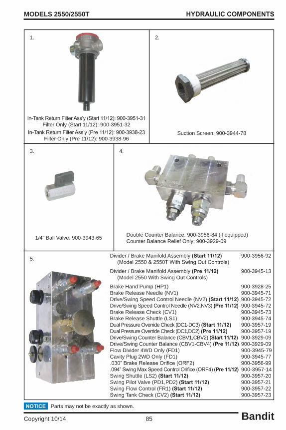
Bandit85Copyright 10/14
MODELS 2550/2550T HYDRAULIC COMPONENTS
Parts may not be exactly as shown.NOTICE
Suction Screen: 900-3944-78
1. 2.
In-TankReturnFilterAss’y(Start11/12):900-3951-31Filter Only (Start 11/12): 900-3951-32
In-TankReturnFilterAss’y(Pre11/12):900-3938-23Filter Only (Pre 11/12): 900-3938-96
3.
1/4” Ball Valve: 900-3943-65 Double Counter Balance: 900-3956-84 (if equipped)Counter Balance Relief Only: 900-3929-09
4.
5. Divider / Brake Manifold Assembly (Start 11/12) 900-3956-92(Model2550&2550TWithSwingOutControls)
Divider / Brake Manifold Assembly (Pre 11/12) 900-3945-13 (Model 2550 With Swing Out Controls)
Brake Hand Pump (HP1) 900-3928-25Brake Release Needle (NV1) 900-3945-71Drive/Swing Speed Control Needle (NV2) (Start 11/12) 900-3945-72Drive/Swing Speed Control Needle (NV2,NV3) (Pre 11/12) 900-3945-72Brake Release Check (CV1) 900-3945-73Brake Release Shuttle (LS1) 900-3945-74Dual Pressure Override Check (DC1-DC3) (Start 11/12) 900-3957-19Dual Pressure Override Check (DC1,DC2) (Pre 11/12) 900-3957-19Drive/Swing Counter Balance (CBV1,CBV2) (Start 11/12) 900-3929-09 Drive/Swing Counter Balance (CBV1-CBV4) (Pre 11/12) 900-3929-09Flow Divider 4WD Only (FD1) 900-3945-79 Cavity Plug 2WD Only (FD1) 900-3945-77 .030”BrakeReleaseOrifice(ORF2) 900-3956-99.094”SwingMaxSpeedControlOrifice(ORF4)(Pre 11/12) 900-3957-14 Swing Shuttle (LS2) (Start 11/12) 900-3957-20Swing Pilot Valve (PD1,PD2) (Start 11/12) 900-3957-21Swing Flow Control (FR1) (Start 11/12) 900-3957-22SwingTankCheck(CV2)(Start 11/12) 900-3957-23

Bandit86Copyright 10/14
MODELS 2550/2550T HYDRAULIC COMPONENTS
Parts may not be exactly as shown.NOTICE
Manual Control Valve - 4 Bank: 900-3952-74
Manual Control Valve - 5 Bank: 900-3952-75
Valve Handle Only: 900-3952-76
1.
2.
3.
Remote Manifold Assembly (Model 2550) 900-3946-01RemoteManifoldAssembly(Model2550T) 900-3960-10
Brake Hand Pump (HP1) 900-3928-25 Brake Release Needle (NV2) 900-3945-71Brake Release Check (CV1,CV2) 900-3945-73Brake Release Shuttle (LS1,LS2) 900-3945-74Dual Pressure Override Check (DC1-DC3) 900-3945-75Drive/Swing Counter Balance (CBV1,CBV2) 900-3929-09Flow Divider 4WD Only (FD1) 900-3945-79 Cavity Plug 2WD Only (FD1) 900-3945-77 Solenoid & Cartridge (SV1-SV5) 900-3934-53Bi-Directional Relief: Swing,Blade, Steer (CR2-CR4) 900-3954-71Main Relief (RV2) 900-3952-66Cutter Wheel Down Relief (RV1) 900-3952-66Drive/Swing Flow Control (FR1,FR2) 900-3957-22.030”BrakeReleaseOrifice(ORF1) 900-3956-99
Dump Valve Block Only: 900-3935-35 (Swing Out Controls)
Solenoid Only: 900-3952-82
Cartridge Only: 900-3952-81

Bandit87Copyright 10/14
MODELS 2550/2550T HYDRAULIC COMPONENTS
Parts may not be exactly as shown.NOTICE
1.
2.
3.
4.
Cutter Wheel Motor: 900-3951-17
Cutter Wheel Motor Manifold Relief: 900-3955-99
Relief Only: 900-3956-04
Drive Motor Without Brake (4WD Option): 900-3947-21
Braking Drive Motor: 900-3947-20

Bandit88Copyright 10/14
MODELS 2550/2550T
Oil Cooler: 900-3952-11
HYDRAULIC COMPONENTS
Parts may not be exactly as shown.NOTICE
1.
2.
3.
Auxiliary Pump 2WD: 900-3956-86
AuxiliaryPump4WD&Tracks:900-3956-87
Cutter Wheel Pump: 900-3955-97

Bandit89Copyright 10/14
MODELS 2550/2550T HYDRAULIC COMPONENTS
Swing Cylinder: 900-3958-80
Steering Cylinder: 900-3937-68
Parts may not be exactly as shown.NOTICE
Cutter Wheel Lift Cylinder: 900-3940-29
Counter Balance Relief Only: 900-3957-08
1.
2.
3.
4.
Grading Blade Cylinder: 900-3946-87

Bandit90Copyright 10/14
MODELS 2550/2550T HYDRAULIC COMPONENTS
Parts may not be exactly as shown.NOTICE
SWING OUT CONTROLS
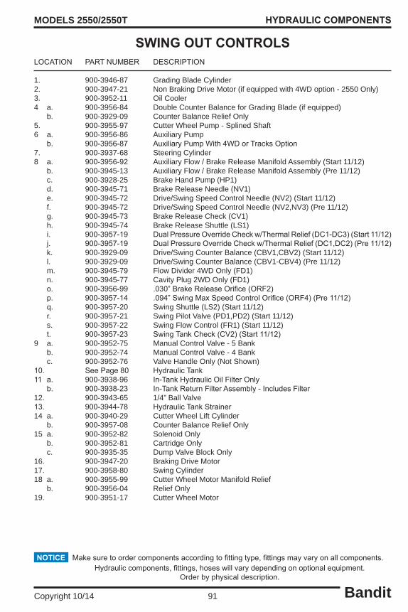
Bandit91Copyright 10/14
MODELS 2550/2550T
LOCATION PARTNUMBER DESCRIPTION
1. 900-3946-87 Grading Blade Cylinder2. 900-3947-21 Non Braking Drive Motor (if equipped with 4WD option - 2550 Only)3. 900-3952-11 Oil Cooler4 a. 900-3956-84 Double Counter Balance for Grading Blade (if equipped) b. 900-3929-09 Counter Balance Relief Only5. 900-3955-97 Cutter Wheel Pump - Splined Shaft6 a. 900-3956-86 Auxiliary Pump b. 900-3956-87 AuxiliaryPumpWith4WDorTracksOption7. 900-3937-68 Steering Cylinder8 a. 900-3956-92 Auxiliary Flow / Brake Release Manifold Assembly (Start 11/12) b. 900-3945-13 Auxiliary Flow / Brake Release Manifold Assembly (Pre 11/12) c. 900-3928-25 Brake Hand Pump (HP1) d. 900-3945-71 Brake Release Needle (NV1) e. 900-3945-72 Drive/Swing Speed Control Needle (NV2) (Start 11/12) f. 900-3945-72 Drive/Swing Speed Control Needle (NV2,NV3) (Pre 11/12) g. 900-3945-73 Brake Release Check (CV1) h. 900-3945-74 Brake Release Shuttle (LS1) i. 900-3957-19 DualPressureOverrideCheckw/ThermalRelief(DC1-DC3)(Start11/12) j. 900-3957-19 DualPressureOverrideCheckw/ThermalRelief(DC1,DC2)(Pre11/12) k. 900-3929-09 Drive/Swing Counter Balance (CBV1,CBV2) (Start 11/12) l. 900-3929-09 Drive/Swing Counter Balance (CBV1-CBV4) (Pre 11/12) m. 900-3945-79 Flow Divider 4WD Only (FD1) n. 900-3945-77 Cavity Plug 2WD Only (FD1) o. 900-3956-99 .030”BrakeReleaseOrifice(ORF2) p. 900-3957-14 .094”SwingMaxSpeedControlOrifice(ORF4)(Pre11/12) q. 900-3957-20 Swing Shuttle (LS2) (Start 11/12) r. 900-3957-21 Swing Pilot Valve (PD1,PD2) (Start 11/12) s. 900-3957-22 Swing Flow Control (FR1) (Start 11/12) t. 900-3957-23 SwingTankCheck(CV2)(Start11/12)9 a. 900-3952-75 Manual Control Valve - 5 Bank b. 900-3952-74 Manual Control Valve - 4 Bank c. 900-3952-76 Valve Handle Only (Not Shown)10. SeePage80 HydraulicTank11 a. 900-3938-96 In-TankHydraulicOilFilterOnly b. 900-3938-23 In-TankReturnFilterAssembly-IncludesFilter12. 900-3943-65 1/4” Ball Valve13. 900-3944-78 HydraulicTankStrainer14 a. 900-3940-29 Cutter Wheel Lift Cylinder b. 900-3957-08 Counter Balance Relief Only15 a. 900-3952-82 Solenoid Only b. 900-3952-81 Cartridge Only c. 900-3935-35 Dump Valve Block Only16. 900-3947-20 Braking Drive Motor17. 900-3958-80 Swing Cylinder18 a. 900-3955-99 Cutter Wheel Motor Manifold Relief b. 900-3956-04 Relief Only19. 900-3951-17 Cutter Wheel Motor
HYDRAULIC COMPONENTS
Makesuretoordercomponentsaccordingtofittingtype,fittingsmayvaryonallcomponents.NOTICEHydrauliccomponents,fittings,hoseswillvarydependingonoptionalequipment.
Order by physical description.
SWING OUT CONTROLS

Bandit92Copyright 10/14
MODELS 2550/2550T HYDRAULIC COMPONENTS
Parts may not be exactly as shown.NOTICE
REMOTE CONTROLS

Bandit93Copyright 10/14
MODELS 2550/2550T
LOCATION PARTNUMBER DESCRIPTION
1. 900-3946-87 Grading Blade Cylinder2. 900-3947-21 Non Braking Drive Motor (if equipped with 4WD option - 2550 Only)3. 900-3952-11 Oil Cooler4. 900-3955-97 Cutter Wheel Pump - Splined Shaft5 a. 900-3956-86 Auxiliary Pump b. 900-3956-87 AuxiliaryPumpWith4WDorTracksOption6. 900-3937-68 Steering Cylinder7 a. 900-3946-01 Remote Manifold Block Assembly (Model 2550) b. 900-3960-10 Remote Manifold Block Assembly (Model 2550) c. 900-3928-25 Brake Hand Pump (HP1) d. 900-3945-71 Brake Release Needle (NV2) e. 900-3945-73 Brake Release Check (CV1,CV2) f. 900-3945-74 Brake Release Shuttle (LS1,LS2) g. 900-3945-75 Dual Pressure Override Check (DC1-DC3) h. 900-3929-09 Drive/Swing Counter Balance (CBV1,CBV2) i. 900-3945-79 Flow Divider 4WD Only (FD1) j. 900-3945-77 Cavity Plug 2WD Only (FD1) k. 900-3934-53 Solenoid & Cartridge (SV1-SV5) l. 900-3954-71 Bi-Directional Relief: Swing,Blade, Steer (CR2-CR4) m. 900-3952-66 Main Relief (RV2) n. 900-3952-66 Cutter Wheel Down Relief (RV1) o. 900-3957-22 Drive/Swing Flow Control (FR1,FR2) p. 900-3956-99 .030”BrakeReleaseOrifice(ORF1)8. SeePage80 HydraulicTank9 a. 900-3938-96 In-TankHydraulicOilFilterOnly b. 900-3938-23 In-TankReturnFilterAssembly-IncludesFilter10. 900-3943-65 1/4” Ball Valve11. 900-3944-78 HydraulicTankStrainer12 a. 900-3940-29 Cutter Wheel Lift Cylinder b. 900-3957-08 Counter Balance Relief Only13. 900-3947-20 Braking Drive Motor14. 900-3958-80 Swing Cylinder15 a. 900-3955-99 Cutter Wheel Motor Manifold Relief b. 900-3956-04 Relief Only16. 900-3951-17 Cutter Wheel Motor
HYDRAULIC COMPONENTS
Makesuretoordercomponentsaccordingtofittingtype,fittingsmayvaryonallcomponents.NOTICEHydrauliccomponents,fittings,hoseswillvarydependingonoptionalequipment.
Order by physical description.
REMOTE CONTROLS

Bandit94Copyright 10/14
MODELS 2550/2550T
SERVICE RECORDSERVICE RECORD
DATE DESCRIPTION AMOUNT