Embed Size (px)
Citation preview

Digital I/O Conversion Module(Cat 1492-CM1771-LD010F)
I. Module
This Digital I/O Conversion Module provides for the conversion of (1) 1771, 16 point I/O modules to be converted to (1) 1756, 16 point I/O module and consists of the following:
(1) 1771 Module (16pt) to (1) 1756 Module (16pt)(2) Conversion Module: 1492-CM1771-LD010F (1) Cable: 1492-CONCAB005Y (Table 2)(1) Conversion Mounting Assembly: 1492-MUA… (Table 1)
This conversion is accomplished without the removal of any field wires from the existing 1771 Swing Arm. The exist-ing 1771 Swing Arm fits directly onto the edge connector of the 1492 Conversion Module. On one end of the 1492 Cable is (1) connector for the Conversion Module. On the other end is the Removable Terminal Block (RTB) for the 1756 I/O module, as shown in the photo below. The I/O signals are routed through the 1492 Conversion Module and the 1492 Cable to the appropriate terminals on the 1756 I/O module per the Wiring Diagrams in Section VI. As stan-dard, both portions of the 1492 Cables are 0.5M long, but we also offer a 1.0M cable length. Refer to the footnotes in Table 2, Section III for further details.
De-energize and lockout any and all power to all I/O field devices connected to the A-B 1771 I/O chassis, and the power to the 1771 I/O chassis itself. Ensure all power is de-energized and locked out to any device in the control cabinet where the conversion is to be performed. Ensure work is performed by qualified personnel.
WARNING
Conversion Compatibility andProduct I.D. Label
37-Pin Connector for cable 1492-CONCAB005Y
PN-114282DIR 10000060093 (Version 01)Publication 1492-IN040B-EN-EPrinted in U.S.A.
1492-CM1771-LD010F Conversion Module
(2)
PN-114282DIR 10000060093 (Version 01)Publication 1492-IN040B-EN-E
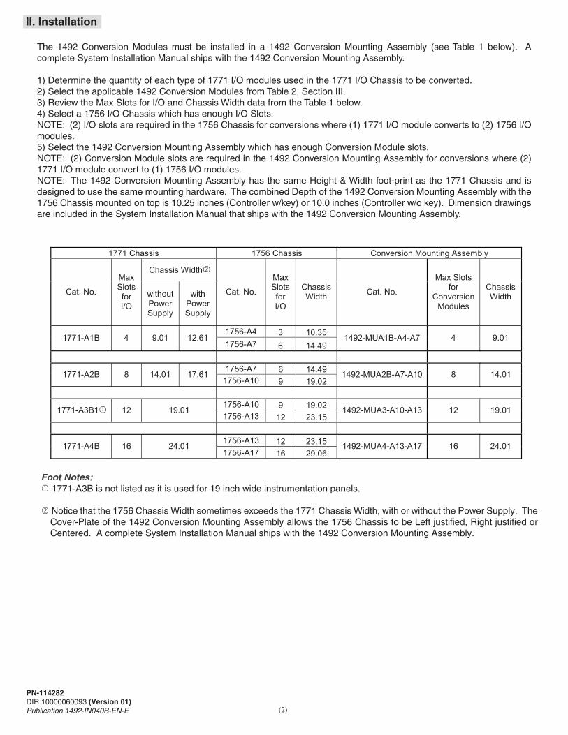
II. Installation
The 1492 Conversion Modules must be installed in a 1492 Conversion Mounting Assembly (see Table 1 below). A complete System Installation Manual ships with the 1492 Conversion Mounting Assembly.
1) Determine the quantity of each type of 1771 I/O modules used in the 1771 I/O Chassis to be converted.2) Select the applicable 1492 Conversion Modules from Table 2, Section III.3) Review the Max Slots for I/O and Chassis Width data from the Table 1 below.4) Select a 1756 I/O Chassis which has enough I/O Slots.NOTE: (2) I/O slots are required in the 1756 Chassis for conversions where (1) 1771 I/O module converts to (2) 1756 I/O modules.5) Select the 1492 Conversion Mounting Assembly which has enough Conversion Module slots.NOTE: (2) Conversion Module slots are required in the 1492 Conversion Mounting Assembly for conversions where (2) 1771 I/O module convert to (1) 1756 I/O modules.NOTE: The 1492 Conversion Mounting Assembly has the same Height & Width foot-print as the 1771 Chassis and is designed to use the same mounting hardware. The combined Depth of the 1492 Conversion Mounting Assembly with the 1756 Chassis mounted on top is 10.25 inches (Controller w/key) or 10.0 inches (Controller w/o key). Dimension drawings are included in the System Installation Manual that ships with the 1492 Conversion Mounting Assembly.
1771 Chassis 1756 Chassis Conversion Mounting Assembly
Chassis Width�
Cat. No.
Max Slots for I/O
without Power Supply
with Power Supply
Cat. No.
Max Slots for I/O
Chassis Width Cat. No.
Max Slots for
Conversion Modules
Chassis Width
1756-A4 3 10.35 1771-A1B 4 9.01 12.61 1756-A7 6 14.49
1492-MUA1B-A4-A7 4 9.01
1756-A7 6 14.49 1771-A2B 8 14.01 17.61
1756-A10 9 19.02 1492-MUA2B-A7-A10 8 14.01
1756-A10 9 19.02 1771-A3B1� 12 19.01 1756-A13 12 23.15
1492-MUA3-A10-A13 12 19.01
1756-A13 12 23.15 1771-A4B 16 24.01 1756-A17 16 29.06
1492-MUA4-A13-A17 16 24.01
Foot Notes:� 1771-A3B is not listed as it is used for 19 inch wide instrumentation panels.
� Notice that the 1756 Chassis Width sometimes exceeds the 1771 Chassis Width, with or without the Power Supply. The Cover-Plate of the 1492 Conversion Mounting Assembly allows the 1756 Chassis to be Left justified, Right justified or Centered. A complete System Installation Manual ships with the 1492 Conversion Mounting Assembly.

(3)
Specification Dimensions
Approximate Shipping Weight
11.81 in. (height) x 4.38 in. (depth) x 1.5 in. (width)300 mm. (height) x 111.25 mm (depth) x 38.1 mm (width)
271.9 g (0.60 lbs) (includes carton) Storage Temperature -40 to +85°C (-40 to +185°F)
Operating Temperature
0 to 60°C (32 to 140°F) Operating Humidity
5 to 95% at 60°C (non-condensing)
Shock Non-operating
Operating
50g 30g Operating Vibration
2g at 10 to 500Hz (Agrees with 1756 I/O module specifications)
Maximum Operating Voltage
132 Vac at 47 to 63Hz
Max. Module Operating Current Per Point: Per Module:
1 Amp4 Amps
4 Amps
Agency Certifications
UL Classified: Under UL File Number E113724
CSA
CE: compliant for all applicable directives
Pollution Degree
2
Environmental Rating
IP20
Refer to the Wiring Diagram(s) for current limits for a specific configuration.
NOTICE
Value
Fusing Sixteen, 1.5 Amps (maximum current based on convensioncomponents)
PN-114282DIR 10000060093 (Version 01)Publication 1492-IN040B-EN-E
IV. Conversion Module Specifications
(Operating specifications are when installed in the Conversion System base / cover-plate assembly)
Table 2: Bulletin 1771 to 1756 Conversion Modules and Cables
III. Compatibility
Foot Notes:�To understand any issues concerning I/O module compatibility, refer to the Installation Manuals for the specific 1771
and 1756 I/O modules involved.
�The 3 numbers indicate the cable length of each portion of the 1492 Cable. Recommended cable lengths of 0.5M are shown. Additional cable lengths are as follows: 1.0M = 1492-CONCAB010Y
1771 Digital I/O Module
1756 Digital I/O Module�
1492 Conversion Module
1492 Cable�
1771-ODD 1756-OA16I 1492-CM1771-LD010F 1492-CONCAB005Y
1771-OQ16
1756-OB16I
1492-CM1771-LD010F
1492-CONCAB005Y 1771-OD16 1756-OA16I
1492-CM1771-LD010F
1492-CONCAB005Y

V. Fuse Installation and Replacement
The 1492-CM1771-LD010F conversion module has sixteen (16) mechanical fuse holders with fuses located on the circuit board inside the modules plastic case. The following explains how to replace the fuses.
1) Remove the 4 screws that hold both halves of the conversion module case together (refer to the following Figure A).
2) Disassemble both case halves so you can access the module’s circuit board. Remove and replace the fuse or fuses (refer to the below Figure B).
3) Reassemble the two case halves to the circuit board and replace the four screws that hold the case together Do NOT over torque the screws (Maximum torque is 5.0 in-lbs.)
NOTES:1) For module operation a fuse must be inserted into the fuse holder2) Physical Fuse Size: 2AG3) Possible Fuse Supplier: LittelFuse (Part Number: 22901.5P)4) Maximum Fuse Current rating based on Conversion System Components: 1.5 Amps
Sixteen Fuse Holders and Fuses
(4)
PN-114282DIR 10000060093 (Version 01)Publication 1492-IN040B-EN-E
FIGURE B
FIGURE A
(5)
PN-114282DIR 10000060093 (Version 01)Publication 1492-IN040B-EN-E
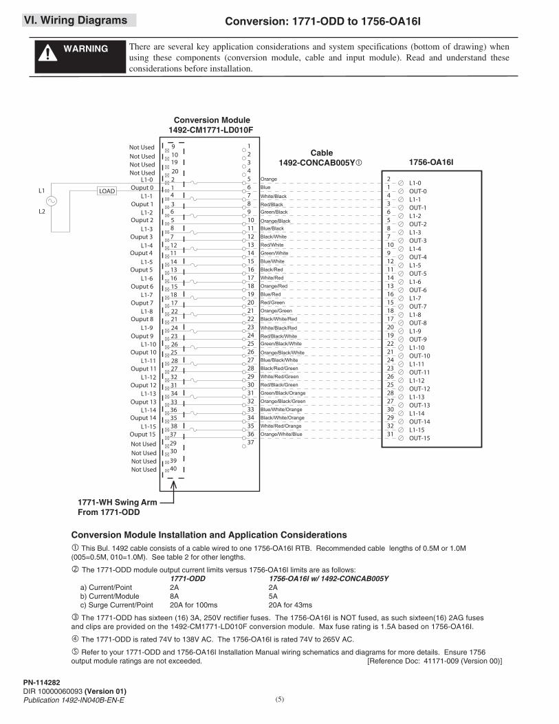
VI. Wiring Diagrams
There are several key application considerations and system specifications (bottom of drawing) when using these components (conversion module, cable and input module). Read and understand these considerations before installation.
WARNING
Conversion Module Installation and Application Considerations� This Bul. 1492 cable consists of a cable wired to one 1756-OA16I RTB. Recommended cable lengths of 0.5M or 1.0M (005=0.5M, 010=1.0M). See table 2 for other lengths.
� The 1771-ODD module output current limits versus 1756-OA16I limits are as follows: 1771-ODD 1756-OA16I w/ 1492-CONCAB005Ya) Current/Point 2A 2Ab) Current/Module 8A 5Ac) Surge Current/Point 20A for 100ms 20A for 43ms
� The 1771-ODD has sixteen (16) 3A, 250V rectifier fuses. The 1756-OA16I is NOT fused, as such sixteen(16) 2AG fuses and clips are provided on the 1492-CM1771-LD010F conversion module. Max fuse rating is 1.5A based on 1756-OA16I.
� The 1771-ODD is rated 74V to 138V AC. The 1756-OA16I is rated 74V to 265V AC.
� Refer to your 1771-ODD and 1756-OA16I Installation Manual wiring schematics and diagrams for more details. Ensure 1756 output module ratings are not exceeded. [Reference Doc: 41171-009 (Version 00)]
12345678910111213
151617181920
14
21222324252627282930313233
353637
34
OUT-0
21
OUT-1
43
OUT-2
65
OUT-3
87
OUT-4
109
OUT-5
1211
OUT-6
1413
Orange
Blue
White/Black
Red/BlackGreen/Black
Orange/BlackBlue/Black
Black/White
Red/White
Green/White
Blue/White
Black/Red
White/Red
Orange/Red
Blue/Red
Red/GreenOUT-7
1615
OUT-8
1817
OUT-9
2019
OUT-10
2221
OUT-11
2423
OUT-12
2625
OUT-13
2827
OUT-14
3029
Orange/Green
Black/White/Red
White/Black/Red
Red/Black/WhiteGreen/Black/White
Orange/Black/WhiteBlue/Black/White
Black/Red/Green
White/Red/Green
Red/Black/Green
Green/Black/Orange
Orange/Black/Green
Blue/White/Orange
Black/White/Orange
White/Red/Orange
Orange/White/BlueOUT-15
3231
L1-0
L1-1
L1-2
L1-3
L1-4
L1-5
L1-6
L1-7
L1-8
L1-9
L1-10
L1-11
L1-12
L1-13
L1-14
L1-15
LOADL1
L2
40
21Ouput 0
3Ouput 1
5Ouput 2
7Ouput 3
11Ouput 4
13Ouput 5
15Ouput 6
17Ouput 7
21Ouput 8
23Ouput 9
25Ouput 10
27Ouput 11
31Ouput 12
33Ouput 13
35Ouput 14
37Ouput 15
L1-0
L1-1
L1-2
L1-3
L1-4
L1-5
L1-6
L1-7
L1-8
L1-9
L1-10
L1-11
L1-12
L1-13
L1-14
L1-15
4
6
8
29
12
14
16
18
30
22
24
26
28
39
32
34
36
38
910
20
19
Not Used
Not UsedNot UsedNot Used
Not Used
Not UsedNot UsedNot Used
1771-WH Swing ArmFrom 1771-ODD
1756-OA16I
Conversion: 1771-ODD to 1756-OA16I
Conversion Module1492-CM1771-LD010F
Cable1492-CONCAB005Y�

(6)
PN-114282DIR 10000060093 (Version 01)Publication 1492-IN040B-EN-E
VI. Wiring Diagrams (Cont’d)
There are several key application considerations and system specifications (bottom of drawing) when using these components (conversion module, cable and input module). Read and understand these considerations before installation.
WARNING
Conversion Module Installation and Application Considerations � This Bul. 1492 cable consists of a cable wired to one 1756-OA16I RTB. Recommended cable lengths of 0.5M or 1.0M (005=0.5M, 010=1.0M). See table 2 for other lengths.
� The 1771-OD16 module output current limits versus 1756-OA16I limits are as follows: 1771-OD16 1756-OA16I w/ 1492-CONCAB005Ya) Current/Point 2A 1Ab) Current/Module 8A 4Ab) Surge Current/Point 20A for 100ms 20A for 43ms
� The 1771-OD16 has sixteen (16) 3A ,250V recifier fuses. The 1756-OA16I is NOT fused,as such sixteen (16) 2AG fuseclips are provided on the 1492-CM1771-LD010F conversion module. Max fuse rating is 1.5A based on 1756-OA16I.
� The 1771-OD16 is rated 74V to 138V AC and 105V to 138V DC. The 1756-OA16I is rated 74V to 265V AC. A1756 isolated output module with an equivalent DC voltage range to convert the1771 -OD16 is not available.
� Refer to your 1771-OD16 and 1756-OA16I Installation Manual wiring schematics and diagrams for more details. Ensure 1756 output module rating are not exceeded. [Reference Doc: 41170-939 (Version 01)]
10 9
19202143
6 5 8 712111413161518172221242326252827323134333635383729303940
Output 10
Output 12
Output 11
Output 13
Output 2
Output 4
Output 3
Output 5
Not Used
Output 0
Not Used
Output 1
Output 6
Output 8
Output 7
Output 9
L1-14 Output 14
L1-15 Output 15
Not usedNot usedNot usedNot used
12345678910111213
151617181920
14
21222324252627282930313233
353637
34
OUT-0
21
OUT-1
43
OUT-2
65
OUT-3
87
OUT-4
109
OUT-5
1211
OUT-6
1413
Orange
Blue
White/Black
Red/BlackGreen/Black
Orange/BlackBlue/Black
Black/White
Red/White
Green/White
Blue/White
Black/Red
White/Red
Orange/Red
Blue/Red
Red/GreenOUT-7
1615
OUT-8
1817
OUT-9
2019
OUT-10
2221
OUT-11
2423
OUT-12
2625
OUT-13
2827
OUT-14
3029
Orange/Green
Black/White/Red
White/Black/Red
Red/Black/WhiteGreen/Black/White
Orange/Black/WhiteBlue/Black/White
Black/Red/Green
White/Red/Green
Red/Black/Green
Green/Black/Orange
Orange/Black/Green
Blue/White/Orange
Black/White/Orange
White/Red/Orange
Orange/White/BlueOUT-15
3231
L1-0
L1-1
L1-2
L1-3
L1-4
L1-5
L1-6
L1-7
L1-8
L1-9
L1-10
L1-11
L1-12
L1-13
L1-14
L1-15
L2
Not Used
Not Used
L1-0
L1-1
L1-2
L1-3
L1-4
L1-5
L1-6
L1-7
L1-8
L1-9
L1-10
L1-11
L1-12
L1-13
LOADL1
1771-WN Swing ArmFrom 1771-OD16
Conversion: 1771-OD16 to 1756-OA16I
Conversion Module1492-CM1771-LD010F
1756-OA16I Cable
1492-CONCAB005Y�

VI. Wiring Diagrams (Cont’d)
There are several key application considerations and system specifications (bottom of drawing) when using these components (conversion module, cable and input module). Read and understand these considerations before installation.
WARNING
� This Bul. 1492 cable consists of a cable wired to one 1756-OB16I RTB. Recommended cable lengths of 0.5M or 1.0M (005=0.5M, 010=1.0M). See table 2 for other lengths.
� The 1771-OQ16 module output current limits versus 1756-OB16I limits are as follows: 1771-OQ16 1756-OB16I w/ 1492-CONCAB005Ya) Current/Point 2A 2Ab) Current/Module 32A 8Ac) Surge Current/Point 4A for 10ms 4A for 10ms
� The 1771-OQ16 has sixteen (16) 3A, 250V rectifier fuses. The 1756-OB16I is NOT fused, as such sixteen(16) 2AG fuses and clips are provided on the 1492-CM1771-LD010F conversion module. Max fuse rating is 1.5A based on 1756-OA16I.
� The 1771-OQ16 is rated 10V to 32V DC. The 1756-OB16I is rated 10V to 30V DC.
� Refer to your 1771-OQ16 and 1756-OB16I Installation Manual wiring schematics and diagrams for more details. Ensure1756 output module ratings are not exceeded. [Reference Doc: 41171-010 (Version 00)]
Conversion Module Installation and Application Considerations
1771-WN Swing ArmFrom 1771-OQ16
(7)
PN-114282DIR 10000060093 (Version 01)Publication 1492-IN040B-EN-E
12345678910111213
151617181920
14
21222324252627282930313233
353637
34
OUT-0
21
OUT-1
43
OUT-2
65
OUT-3
87
OUT-4
109
OUT-5
1211
OUT-6
1413
Orange
Blue
White/Black
Red/BlackGreen/Black
Orange/BlackBlue/Black
Black/White
Red/White
Green/White
Blue/White
Black/Red
White/Red
Orange/Red
Blue/Red
Red/GreenOUT-7
1615
OUT-8
1817
OUT-9
2019
OUT-10
2221
OUT-11
2423
OUT-12
2625
OUT-13
2827
OUT-14
3029
Orange/Green
Black/White/Red
White/Black/Red
Red/Black/WhiteGreen/Black/White
Orange/Black/WhiteBlue/Black/White
Black/Red/Green
White/Red/Green
Red/Black/Green
Green/Black/Orange
Orange/Black/Green
Blue/White/Orange
Black/White/Orange
White/Red/Orange
Orange/White/BlueOUT-15
3231
DC-0
DC-1
DC-2
DC-3
DC-4
DC-5
DC-6
DC-7
DC-8
DC-9
DC-10
DC-11
DC-12
DC-13
DC-14
DC-15
+
-
40
21Ouput 0
3Ouput 1
5Ouput 2
7Ouput 3
11Ouput 4
13Ouput 5
15Ouput 6
17Ouput 7
21Ouput 8
23Ouput 9
25Ouput 10
27Ouput 11
31Ouput 12
33Ouput 13
35Ouput 14
37Ouput 15
DC-0
DC-1
DC-2
DC-3
DC-4
DC-5
DC-6
DC-7
DC-8
DC-9
DC-10
DC-11
DC-12
DC-13
DC-14
DC-15
4
6
8
29
12
14
16
18
30
22
24
26
28
39
32
34
36
38
910
20
19
Not Used
Not UsedNot UsedNot Used
Not Used
Not UsedNot UsedNot Used
LOAD
Conversion: 1771-OQ16 to 1756-OB16I
Conversion Module1492-CM1771-LD010F
1756-OB16I Cable
1492-CONCAB005Y�

PN-114282DIR 10000060093 (Version 01)Publication 1492-IN040B-EN-EPrinted in U.S.A.

CONFIDENTIAL AND PROPRIETARY INFORMATION. THIS DOCUMENT CONTAINS CONFIDENTIAL AND PROPRIETARY INFORMATION OF
ROCKWELL AUTOMATION, INC. AND MAY NOT BE USED, COPIED OR DISCLOSED TO OTHERS, EXCEPT WITH THE AUTHORIZED WRITTEN
PERMISSION OF ROCKWELL AUTOMATION, INC.
Sheet
Size Ver
Of 11
A 0010000188011Dr. DateG. USHAKOW 06-07-11
MATERIALSIZE
FOLD
TWO SIDES PRINTEDBODY STOCK WHITE
BODY INK BLACK4-1/4" W x 11" H
FLAT
17" W x 11" H
SPECIFICATIONS FOR8 PAGE INSTRUCTION SHEET4-1/4” W x 11” H - FINAL FOLD
Page Layout
8 - 1/2"8 - 1/2"
17" 17"
Front SidePage 1
Back SidePage 2
Front SidePage 8
Back SidePage 7
Front Side
Saddle Stitched Saddle Stitched
Page 3
Back SidePage 4
Front SidePage 6
Back SidePage 5
8 - 1/2"8 - 1/2"
Final Fold
11”4-1/4”
Note: After folding---Printed in (Country where printed)* and instruction sheet number in lower left corner should be visible.
* The printing vendor may change the instruction sheet files to show the correct country.
PN-12345DIR 100000000 (Version 00)Printed in U.S.A.
11"