Embed Size (px)
Citation preview

IACS Common Structural Rules Knowledge Centre
Bulker Q&As and CIs on the IACS CSR Knowledge Centre
KCIDNo. Ref. Type Topic Date
completed Question/CI Answer Attachment
220 8/1.1.3.1 Questionfatigue
strengthassessment
2006/11/22The number of members and locations to be assessed is many.We would liketo ask you to reduce the number of locations taking into account damageexperience and your calculation results.
The members and locations subjected to fatigue strength assessmentdescribed in Table 1 of Ch 8 Sec 1 are of the members and locations whichthe fatigue damage are occurred in the past, even though the number ofdamages are neglected. Therefore, the fatigue strength assessment should becarried out for the structural details specified in Table 1.
221 8/2.2.3.1 Question fillet weld 2006/11/8
There is no category for welded joint of sloped plate and horizontal plate suchas hopper knuckle and lower stool in Table 1.Our understanding is as follows,because Frank angle of the weld joint is lesser than fillet weld:"Kf=1.25 forwelded joint of sloped plate and horizontal plate"Please confirm the above assoon as possible.
The fatigue notch factor Kf of 1.25 for welded joints of sloped plate andhorizontal plate such as hopper knuckle and lower stool can be appliedbecause their welded joints are classified with the load carrying full penetrationweld joints as well as butt welded joint. For the non-load carrying fullpenetration welded joints between plate, the fatigue notch factor Kf may bereduced.
222 8/2.2.3.2 Question fatiguedamage 2006/11/28
The correction factor for mean stress is very complicated and sensitive tofatigue damage. Please reconsider and revise the factor to meet ourengineering sense as soon as possible.
According to the fatigue damage experiences, mean stress effect is the mostdominant factor to explain their fatigue damage. Then, the precise procedureto consider the mean stress effect is mentioned in the text. However, tosimplify the procedure for the mean stress effect without losing the accuracy ofthe present fatigue assessment needs much time, careful discusstion andappropriate ramification study. Therefore, for the time being, the text is kept asit is.
223 8/5.3.1.1 Question nominalstress range 2006/12/22
We understand that the nominal stress range obtained from this formula isbending stress of the cross deck.Thus the stress occurs in athwartshipdirection.In general, the major axis is arranged in longitudinal direction toreduce the stress concentration due to hull girder bending moment.Thereforethe explanation of ra and rb is not adequate to use the formula properly.Forexample, ra and rb are inner radius and outer radius, respectively.This rulebrings very pessimistic results.In conjunction with the above comment, therules should be revised to obtain reliable results as soon as possible
The requirement on hatch corner fatigue check will be revised as soon aspossible, including a technical background.
Page 1 of 10

IACS Common Structural Rules Knowledge Centre
KCIDNo. Ref. Type Topic Date
completed Question/CI Answer Attachment
250 8/2.2.3.2 Question hot spotstress range 2006/11/10 Equivalent hot spot stress range (Corrigenda 1) This item seems to be rule
change. We would like to know the impact of this rule change.
This revision includes the correction of the factor in the conditional equationsand the alternation of the expression. The correction of the factor in theconditional equations is made for the simple error in writing of the factor in thecondition that the shakedown in compression stress side is occurred. Thiscondition correspond the case that the large mean stress in compression sideis occurred. The effect of this correction on the scantlings of the structuralmember is very small since the fatigue damage in such case is negligiblesmall. The alternation of the expression is made to clarify the meaning of theconditional equations without changing the conditions.
251 8/3.2.2.2 Question FE model 2006/11/10
In Chapter 8 Section 3 / 2.2.2, the calculation of hull girder stresses for thecomputation of fatigue life by direct strength analysis using superimpositionmethod does not take into account the hull girder bending moments that existin the FE model due to the local loads. Consequently, some of the hull girderbending stress is considered twice.
The bending moments induced on the FE model by local loads are explicitlytaken into account when using superimposition method for yielding andbuckling criteria (Cf Ch 7, Sec 2, [2.5.7]), and it seems necessary to proceedin the same way for fatigue. Note: Ch 8, Sec 2, [2.2.2] should make referenceto Ch 7, Sec 2, [2.5.7].
253 Fig 8.5.2 Question Sectionmodulus 2006/12/20
When calculating section modulus of the cross deck Wq and moment ofinertia of the cross deck Iq, how to determine the neutral axis? Is it axis z ?Please clarify it.
IQ and WQ are to be determined about z-axis. In order to clarify the difinitionof WQ and IQ, the editorial change will be issued as Corrigenda.
255 Table8.4.1 Question watertight 2006/12/11
In Chapter 8 Section 4, Table 1, some details, in the "watertight" cases seemsto be similar (two by two): "3" and "10"; "7" and "12" or "8" and "14". But thevalues of the stress concentration factors differs from a detail to another. Anharmonization of the SCF between these details is needed, in order to applythe right ones.
It is right that the details 3 and 10 (7/12 and 8/14) are very similar for the case"watertight". An harmonization should be very helpful. More generally, eachdetail should appear only once in the Table with SCF for the two assessedpoints, and for both cases "watertight" and "non-watertight". It should beconsidered as a Rule Change
256 Table8.4.1 Question watertight 2006/11/23
In Chapter 8 Section 4, Table 1, the meaning of "watertight" and "non-watertight" in the column "collar plate" is not clear: does it mean that a collarplate is required in any case? Or does it mean that "watertight" is equivalent toa full collar plate and "non-watertight" is equivalent to a partial collar plate?|
A collar plate is not required in all cases."Watertight" means that a full collarplate is fitted, and "non -watertight" means other cases: no collar plate is fittedor a partial collar plate is fitted.It should be better to replace "watertight" by "fullcollar plate" and "non-watertight" by "other cases".
Page 2 of 10

IACS Common Structural Rules Knowledge Centre
KCIDNo. Ref. Type Topic Date
completed Question/CI Answer Attachment
257 Table8.4.1 Question watertight 2006/11/18
In Chapter 8 Section 4, Table 1, for details 1 to 8, stress concentration factorsare indicated for both cases 'watertight' and 'weathertight' for one of theassessed point and for case 'watertight' only for the other assessed point.What are the values to consider the stress concentration factors in case 'non-watertight' for this later point?
In the case 'non-watertight', the missing stress concentration factors for one ofthe two points leads to less severe results in fatigue. That is the reason whythe values of the SCF are not indiciated. However, our point of view is to addthese values in the Table in order to be coherent.
258 Table8.4.1 Question watertight 2006/12/13
In Chapter 8 Section 4, Table 1, a detail is missing: the one correspondingwith detail 1, but without vertical stiffener. What are the values to consider forthe stress concentration factors for such a detail?
For a detail corresponding to detail 1, but without vertical stiffener nor bracket,SCFs should be developed.
259 Table8.4.1 Question Aft & Fore 2006/11/23
|In Chapter 8 Section 4, Table 1, the meaning of "Aft" and "Fore" is not clear:does it mean aft and fore ends of the ship, or aft and fore ends of the stiffenerconsidered, or is it only a way to identify both sides of the detail?
"Aft" and "Fore" does not mean aft anf fore part of the ship. They are to beunderstood as being one side and the other side of the considered detail. Itshould be better to give a name to the two assessed points, i.e. "Point A" and"Point B", and to modify the schemes accordingly ("A" and "B" instead of "a"anf "f", and delete "Aft" and "Fore".
277 8/2.2.3.2 Question conditionalequations 2006/11/23 This item seems to be rule change.We would like to know the impact due to
this change.
This revision includes the correction of the factor in the conditional equationsand the alternation of the expression. The correction of the factor in theconditional equations is made for the simple error in writing of the factor in thecondition that the shakedown in compression stress side is occurred. Thiscondition correspond the case that the large mean stress in compression sideis occurred. The effect of this correction on the scantlings of the structuralmember is very small since the fatigue damage in such case is negligiblesmall. The alternation of the expression is made to clarify the meaning of theconditional equations without changing the conditions.
Page 3 of 10

IACS Common Structural Rules Knowledge Centre
KCIDNo. Ref. Type Topic Date
completed Question/CI Answer Attachment
2868/1.1.3.1 &
Table8.1.1
Questionfatigue
strengthassessment
2006/12/13
List of locations subject to fatigue strength assessment:a) For ships having length L of 150 m or above, are there any circumstancesunder which fatigue assessment of the locations listed in the Table can bewaived?b) Is each detail to be assessed for location in homogeneous hold, ore holdand ballast hold? (This question is based on actual cases of different Classgiving different opinions of the locations requiring fatigue assessment basedon actual designs in progress.)
a)No in general. The members and locations subjected to fatigue strengthassessment described in Table 1 of Ch 8 Sec 1 are of the members andlocations which the fatigue damage are occurred in the past, even though thenumber of damages are neglected. Therefore, the fatigue strengthassessment should be carried out for the structural details specified in Table 1.b)If the arrangement and scantling of the detailed to be assessed in holds aredifferent, each detail should be assessed.
342attc 8/4.2.3.6 Question Transverse
BHD 2007/5/22 Relative displacement of transverse BHD.See the attached question.
The relative deflection for double bottom is defined as follows.(1) On the bottomThe base line is defined as the line between connecting points of the floors tobottom in way of fore and aft of lower stools. The relative deflection is definedas the deflection of the connecting points of the adjacent floors to bottommeasured from the base line.(2) On side shellThe case 2 as shown in your attached document is correct.
Y
355 8/5.2.1.1 Question Parametercorrection 2007/3/20
In Chapter 8 Section 5,[2.1.1], the following parameters needs to be morespecific:1) "AQ" is the shear area of the cross deck: does it includes the shear area ofall plates and of all ordinary stiffenerd, as shown on Figure 2 ?2)"bS" is the breadth of the remaining deck strip beside the hatch opening: is itthe total breadth on both sides or is it only on one side? If it is the latest case,it should be identical to "b" defined in [3.1.1].3) "LC" is the length of the cargo area, it should be noted LC, with "C" as andindex.
1) The shear area "AQ" is the effective shear area of the whole section shownin figure 2 with respect to the ship's longitudinal direction. For the deterninationof the effective shear area the consideration of only the plate elements issufficient, and the stiffeners can be neglected.2) "bs" is only the reamaining deck strip on one side, so it is identical to "b" in[3.1.1]3) This is an editorial typo: "C" should be as an index in "LC".Also Included in Corrigenda 5
Page 4 of 10

IACS Common Structural Rules Knowledge Centre
KCIDNo. Ref. Type Topic Date
completed Question/CI Answer Attachment
Please review the below questions related to Fatigue calculations.Q1: Loading conditions and assumptions. Fatigue calculation is performed inthe following 4 load condition; Homogenous, Alternate, Ballast and Heavyballast. The design loading condition for FEM is listed in Ch. 4 App.3. Arethese conditions also applicable for prescriptive calculation of stiffenerconnection according to Ch. 8 Sec. 4? Following differences are fond betweenCh.8 Sec. 4 and Ch. 4 App. 3: a.Filling height and density for Homogenouscondition. According to Ch. 8 Sec. 4 [2.3.5] the definition of Ch.4 Sec. 6 [1.3]should be applied. That is � = max(MH/VH,1) and filling to main deck.According to Ch.4App.3 the � = MH/VH with filling height to main deck.b.Heavy fuel oil tanks(HFO). According to Ch.8 Sec.4 [2.3.4] the filling heightof HFO tanks may be taken as “half height of the tank”. According to Ch.4App.3 the HFO tanks is full. Q2: Partially filled ballast tanks. Please advice ifall ballast tanks are 100% for the purpose of fatigue calculations?
A1 The same loading condition should be applied to both direct strengthanalysis and prescriptive requirement for fatigue check.(a) rho_c = MH/VH and filling to upper deck may be applied to.(b) Fuel oil is always filled to half the height of FOT.A2: Tanks other than Water Ballast Tanks are considered as being filled at50%. All Water Ballast Tanks are considered either full or empty. Even thoughsuch WBT are intended to be partially filled at the standard loading condition,the partial filling of such tanks is not considered for fatigue check.A3:(a) Yes, actual still water bending moment in the Loading Manual for therespective loading conditions may be used for fatigue strength assessment.(b) The requirement of Chapter 4 Section 3, 2.2.1 mentions that “The designstill water bending moment, MSW,H and MSW, S, at any hull transversesection are the maximum still water bending moment calculated, in hoggingand sagging condition, respectively, at that hull transverse section for theloading conditions, as defined in 2.1.1.”.
Q3: Still water bending moment We assume the actual still water bendingmoment in the Loading Manual for the respective loading conditions may beused for the fatigue calculations. Please confirm. Please also clarify whichconditions to use, departure, arrival or max./average? Q4: Partially filledHeavy fuel oil tanks. According to Ch. 8 Sec. 4 [2.3.4] the HFO tanks areindicated as half full when calculating CNI factor. Please advise on thefollowing related items: a.The dynamic pressure is calculated according toCh.4 Sec.6 [2.2.1]. The equation is, as far as we can see, developed basedon a full tank. How is this modified to account for filling height? Can thisequation be used as is with respect to Ztop and reference point (xB,yB,zB). ?b.Mean stress and still water pressure according to Ch.8 Sec.4 [3.3.4]. Thestatic pressure is calculated according to Ch.4 Sec.6 [2.1]. This still waterpressure is assuming PBS = �Lg(zTOP-z+0.5dAP) or �Lg(zTOP-z)+100PPVwhichever is greatest. Minimum 25kN/m2. How is this modified to treatpartially filled tanks? c.We assume ballast exchange operation is not applicable doing fatigue calculations? Please confirm.
Therefore, the loading condition is to be used which gives the maximum stillwater bending moment among the considered loading conditions, i.e.,departure, arrival and intermediate conditions specified in Loading Manual.A4:(a) Yes, the equation in Ch.4 Sec.6 [2.2.1] may be used as is, provided; -Liquid surface level at mid-height of the tank may be assumed to remainunchanged relative to tank geometry even when hull motion should occur, -Ztop may be taken as the Z-coordinate, in m, of the Liquid surface level atmid-height of the tank, and - xB, yB and zB may be taken on the Liquidsurface level at mid-height of the tank.(b) Ztop may be taken as mentioned in (a).(c) We confirm that ballast exchange operation is not applicable. Please notethat Min.25kN/m2 is not applicable to fatigue strength assessment.
8/4.2.3.4,8/4.2.3.5 &
4.3.3.4Question Fatigue
Calculations 2007/7/2359
Page 5 of 10

IACS Common Structural Rules Knowledge Centre
KCIDNo. Ref. Type Topic Date
completed Question/CI Answer Attachment
1) That is right: the stiffeners are not to be considered in the calculation of theproperties of the cross section. Only the plates are to be considered as "partialarea" (defined in [1.1.1]).2) The parameter "yS" which appears in the calculation of "Iz" for symmetriccross section should be considered equal to zero. By defining it in the sameway as for asymmetric cross section, it comes equal to zero, as "Sz" should beequal to zero for such symmetric cross secton.3) We agree that using twice the same symbol for different definitions isconfusing, It should be corrected. However, your understanding is correct: theparameter "Iwy" used in the definition of "Iw" is also the one defined in Table1.4.4) That is right, this is a typo: in Table 1.4, for symmetric cross section, in thedefinition of " Iw", "zm" should be understood as "zM".5) in the statement "S, Iw are to be computed with relation to shear centre M","S" is to be understood as being "Sy", "Sz" and "Sw" in the list of formulae atthe beginning of [1.3.1], and "Iw" is to be understood as being "Iw", "Iwy" andIwz". It means that in such expressions the coordinates "yk", "yi", "zk" and "zi"are to be considered also in reltion with the shear centre M.6) We agree that the formula giving "Delta w" is not clear. The formula shouldbe replaced by: "Delta wi = zM * yi". In order to clarify all symbols in Chapter8 Appendix 1, we will consider the rule change proposal.the coordinates "yk","yi", "zk" and "zi" are to be considered also in reltion with the shear centre M.
385attc 8/5/3.1.1 Question Elliptic
Corners 2007/3/9
We have some doubts on the correction factor for elliptic corners whichappears in the formula of the stress concentration factor in Ch 8, Sec 5,[3.1.1]. We see on the knowledge centre under the answer to question 223that "The requirement on hatch corner fatigue check will be revised as soonas possible, including a technical background". However, to help for thisrevision, we would like to ask you to consider the attached document. It showsthat some misunderstanding has occurred between "ra" and "rb". Pleaseconsider this proposal?
Having considered your attached document, it seems effectively that “ra” and“rb” are not defined correctly. We will consider it at the time of revision of thisrequirement.
Y
CalculationChange 2007/3/9
In Chapter 8, Appendix 1, [1.3.1], the following items needs some clarification:1) it is understood that the stiffeners are not considered in the calculation ofthe properties of the cross section. Please confirm?2) In table 1.4, for symmetric cross section, the parameter "yS" appears in thecalculation of "Iz", but is not defined. What is the definition of "yS" in such acase?3) in table 1.4, for symmetric cross section, it is understood that theparameters "Iwy" and "Iz" which appears in the definition of "zM" arethoseparameters defined just above in the table, and not those defined in thebeginning of [1.3.1]. Please confirm? Using twice the same symbol fordifferent definitions is confusing. The same understanding is considered forthe parameter "Iwy", used in the definition of "Iw".4) In Table 1.4, for symmetric cross secton, in the definitionof "Iw", it should be"zM" instead of "zm".5) Below Table 1.4, it is stated that "S, Iw are to be computed with relation toshear centre M". What are the meaning of "s" and "Iw" in this statement? 6)The formula giving "Deltaw" is not clear. Please explain?
375 8/App.1,1.3.1 Question
Page 6 of 10

IACS Common Structural Rules Knowledge Centre
KCIDNo. Ref. Type Topic Date
completed Question/CI Answer Attachment
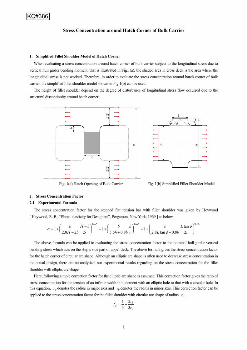
386attc 8/5.3.1.1 Question Formula
"Kgh" 2007/4/25It seems that there is a mistake in the definition of the term “b” in the formuladefining “Kgh”. We think that “b” should be twice the distance from the edge ofhatch opening to the ship’s side. Please confirm our interpretation?
It is right, there is a mistake in the formula of “Kgh”. See the technicalbackground attached, in which it is clearly shown on figure 1(b) that “b” shouldbe twice the distance from the edges of hatch opening to the ship’s side. So,the definition of “b” may remains the same as it is, but the formula of “Kgh”should be modified accordingly by replacing the term “b” by “2b”.Also Included in Corrigenda 5
Y
452Table
8.1.1 &8/1.1.3.1
RCPfatigue
strengthassessment
2009/10/6
It is requested from interpretation point of view that the members andlocations to be assessed for fatigue strength can be waived with a proviso. Itis considered unnecessary to assess fatigue strength by FEM analysis forevery location in Table 1 in particular any taken as less significant. Fatigueassessment by FEM should be streamlined to be more practical to focus oncritical locations such as lower hopper corners and lower stool connectionswith inner bottom considering selective cargo holds.
We noted your comment and this issue has been addressed in RCN No.3(issued September 2008).
The matter leads to a rule change proposal. As a result of our detailed fatiguestrength calculation based on simplified method for lower hopper corners andlower stool connections with inner bottom of a panamax bulk carrier, it is foundthat the fatigue life of these locations is impractically too short. Moreover, it isfound that the fatigue life calculated for lower hopper corners in the emptyhold is shorter than that in the ballast hold in both cases of bent and weldedcorners, which is in serious contradiction of the ubiquitous fact of experience.The least fatigue life calculated is only a few years at a lower stool connectionin the ore hold for which no way of designing to achieve the prescriptivefatigue life of 25 years could be possible.
603attc 8/4.2.3.6 CI
Displacement of
transversebulkhead.
2008/4/18
JBP rules Chapter 8,Section 4.2.3.6 Stress due to relative displacement oftransverse bulkhead. There are 3 questions:Q1. Is the relative displacement an absolute value or with a sign?Q2. If it is not absolute value, how to decide the sign of them?Q3. We understand that this additional stress is only applied at thetransververse bulkhead. This additional stress is not required for the ringsadjacent to the transverse bulkhead.
Regarding the requirement in Ch 8, Sec 4, [2.3.6], please find our answers.A1: The relative displacements are not absolute value. They should becalculated with signs (+ or -);A2: The signs of the displacements are decided as per the rules in theattachment;A3: Your understanding is correct and comfirmed.
Y
635attc
Table8.4.1 CI
Stressconcentration
factors2008/3/26
Regarding the stress concentration factors given in the Rules Chapter 8,Section 4, Table 1, it is understood that where values are given only forconnections with watertight collar plates fitted, these are also applicable forconnections with non-watertight collar plate or no collar plate fitted. NK BulletinNo.276, 2006 refers. (in Japanese)Please confirm.
Your understanding is correct.
We will consider the rule change proposal in order clarify this.Y
Page 7 of 10

IACS Common Structural Rules Knowledge Centre
KCIDNo. Ref. Type Topic Date
completed Question/CI Answer Attachment
688 8/4.2.3.3 QuestionFatigure of
stiffener endconnection
2008/5/28
Reference is made to Ch.8 Sec.4 [2.3.3] – Fatigue of stiffener end connection– Stress due to wave pressureDesign pressure in the formula is CNE x pw.pw should be calculated according to Ch. 4 Sec. 5 [1.3], [1.4], [1.5]Ch. 4 Sec.5 [1.1.1] is generally valid for Section 5. Quote “The total pressure pat any point of the hull, in kN/m2, to be obtained from the following formula isnot to be negative: p=pS+pw.” UnquoteIt is unclear whether or not [1.1.1] is valid for pressure calculation for Ch.8Sec.4 [2.3.3].Please note that if no correction to the dynamic pressure is made, the totaldynamic pressure for side longitudinals right below the water line is larger thanthe static pressure at the same location, that is Ps+(CNE x pw) < 0. This is incontraddiction to the general statement in Ch.4 Sec.5 [1.1.1]Q1: Is the statement of Ch.4 Sec. 5 [1.1.1] valid when calculating seapressure for Ch.8 Sec.4 [2.3.3]?Q2: If yes, it is assumed that Ch.4 Sec.5 [1.6.2] should be used for correctingthe dynamic sea pressure. Please advice how to apply [1.6.2]:
The statement of Ch 4 Sec 5, [1.1.1] is not valid when calculating seapressure according to Ch 8 Sec 4, [2.3.3]. Becasue Ch 8 Sec 4, [2.3.3] isconcerned only the hydrodynamic pressure, not the static pressure.The statement of Ch4 Sec5[1.1.1] is only applicable to the one wave state.When a wave, which has a certain wave height, is acting on the ship's side,wave pressure has to be corrected so as not to generate negative pressure.Therefore the degree of correction is different by the wave height although thecorrection procedure is the same.The statement of Ch8 Sec4[2.3.3] is introduced to obtain the expected wavecondition considering the stochastic nature of wave height so as to evaluatestress range for fatigue assessment.
a.No correction according to [1.6.2] is made for pw when calculating CNE?b.Correction of dynamic pressure according to [1.6.2] for the total dynamicpressure pw = CNE x pw(uncorrected)?
742attc
Table8.1.1 Question FEA 2008/10/10 See the attached Question. It has multiple questions, however, for the sake of
easy reference, they are grouped as one Question.
A-1 Structural members can be evaluated by the simplified method accordingto the specification in Ch 7 Sec 4 [3.3] if applicable, except for the followingmembers: hold frames of single side bulk carriers, connections betweencorrugations and stools and ordinary stiffeners in double side space at theconnection of transverse stiffeners with stringer or similar. Where the fatigueassessment is carried out by the very fine mesh FEA, all cargo holds shouldbe evaluated. If the structural details in cargo holds other than heavy ballasthold are the same as those in heavy ballast hold and the evaluated results ofthose in heavy ballast hold are satisfactory, the very fine FEA for cargo holdsother than heavy ballast hold can be omitted.A-2 The transverse BHD connection with vertical lower stool and upper stoolas well as sloping ones should be checked.A-3. Only representative locations should be checked.
Y
Page 8 of 10

IACS Common Structural Rules Knowledge Centre
KCIDNo. Ref. Type Topic Date
completed Question/CI Answer Attachment
743 Figure8.5.2 Question Co-ordinate
"Y" 2008/7/2 Ch 8 Sec 5 Figure 2 indicates coordinates. Is the co-ordinate "Y" typo? Shouldit be "X" ? . Yes, it is typo. We will consider a rule change.
812 8/4.2.3.2 QuestionStress
concentrationfactors
2009/3/3
Geometrical stress concentration factor for stress due to lateral pressure,K_gl, is permitted to be evaluated directly by FEM according to Ch8 Sec4,2.3.3. However, no indications of direct evaluation by FEM are found in thedefinition of geometrical stress concentration factor for stress due to hull girdermoments, K_gh, in Ch8 Sec4, 2.3.2.Please confirm whether geometrical stress concentration factor for stress dueto hull girder moments, K_gh, can be evaluated directly by FEM.
The geometrical stress concentration factor for stress due to hull girdermoments, K_gh is also be able to evaluated directly by FEM. This is includedin RCP 4 which has been reviewed according to PR 32.
8548/1.1.3.1 &
Table8.1.1
QuestionPrimarySupport
Members2009/3/10
Table 1 of Ch8, Sec1 defines the members and locations to be analysed infatigue assessments. Each mentioned connection of primary supportingmembers is analysed in only one direction. We see the necessity to evaluatea connection from both sides. This question focus' on the connection of innerbottom and lower stool.. Summary of experience with fatigue assessment ofheavy ballast cargo holds: + The connection of the inner bottom to thevertical/sloping plate of the lower stool is the most critical loaction + Thedeformation of the double bottom and the transverse bulkhead expand thiswelding connection due the large internal dynamic pressures . + The globalbending stress plays not a dominant role. Stress ranges of the inner bottomand the stool plating are of a comparable size + Typically the initial calculateddamages of the inner bottom AND the stool plate are considerably larger than1. + Counter measures in one member, e.g inserted plates in inner bootom,decrease the damage of this member, but increase the damage of the othermember.
This is already under discussion at the Hull Panel. The conclusions will beendorsed by PT1. UPDATED ANSWER AGREED 11 SEPT 2009: "Regarding Tab1 in Ch 8, Sec 1 of CSR-BC, the intent at the time of development of the CSR-BC was not to check the inner bottom only, but the whole connection of innerbottom with sloping and/or vertical plate of lower stool, which includes all theplates. The whole connection means the connection of plating members ofinner bottom, side of lower stool, girders and floors in DB and diaphragms inlower stool. In addition, it is to be noted that, when making fatigue assessmentof such connection, if fatigue problems are found in any of the above platingmembers, then reinforcements are to be considered for all the concernedplating members. It means that Table 1 should be understood as consideringall the plating members involved in the inner bottom/lower stool connectionand not only the inner bottom plating. Table 1 will be modified accordingly at afuture date."
As an example, the reduction of the damage of the inner bottom from 4 to 1may increase the damage of the sloping plate up to 6 or more. Thedeformation and stresses of the considered structure and the damage resultsindicate clearly that this fatigue problem is a 3D-problem, where measures inone member directly affects the other member. If we follow the definition ofmembers, to be assessed (Table 1), only the inner bottom need to complywith the fatigue requirements, whatever the calculated damage of the stoolplating is. It seems, there are two options: 1) Assess the inner bottom - lowerstool connection from both sides. 2) Assess only the inner bottom In case ofoption 1, we need a modification of the table and we need an instruction, howto deal with approved vessels (MOU, TOCA), where no fatigue assessmenthave been performed for the stool plating. In case of option 2, it has to bedemonstrated, why the damage results of the lower stool plating can beneglected.
Page 9 of 10

IACS Common Structural Rules Knowledge Centre
KCIDNo. Ref. Type Topic Date
completed Question/CI Answer Attachment
858 8/2.3.2.1 Question shapeparameter 2009/2/11
In CSR BC Ch.8 Sec.2 [3.2.1], the Weibull shape parameter is taken to 1.0. InCSR OT App. C/2.4.1.2, this parameter is a linear function of the rule length L.Using in CSR BC the same definition of Weibull shape parameter as in CSROT leads to longer fatigue life duration. As the approach used in CSR OT isalso used in BV rules and in other societies, it is therefore requested toreconsider the value of in 1.0 for this parameter in CSR BC.
Originally, the Weibull shape parameter, which is the function of L, wasdefined for the wave bending moment in the IACS Recommendation No.56 in1999. Strictly, it depends on the RAO of the object member and consideredload environments. In the CSR-B, the Weibull shape parameter was set as 1.0for the simplification and the effect of such treatment is confirmed being small.The point you mentioned should be the harmonization issue and will bediscussed in the forthcoming harmonization team on fatigue.
875attc
Table8.2.2 Question fatigue
strength 2009/9/3
In practice, there are some bulk carriers without heavy ballast condition. Howis fatigue strength checked? Especially, how is the coefficient αj determinedwhich is defined in Ch8, /Sec 2, /Table 2? Is it practical to incorporate αj inheavy ballast condition into that in normal ballast condition as the followingtable (as attached)?
Normal ballast condition and heavy ballast condition are required for allvessels with CSR Bulk Carrier notation for providing sufficient draught and trimto prevent damages during navigation in Ch.4 Sec.7 [2.2.1]. In case that abulk carrier does not have a ballast hold and has only one loading conditioncarrying ballast water and that the loading condition complies with the bothrequirements of normal ballast condition and heavy ballast condition in Ch.4Sec.7 [2.2.1], the loading condition may be treated as normal ballast conditionand heavy ballast condition stipulated in Ch.8 Sec.2, Table 2. Coefficientalpha_j in Ch.8 Sec.2, Table 2 should be applied accordingly.
Y
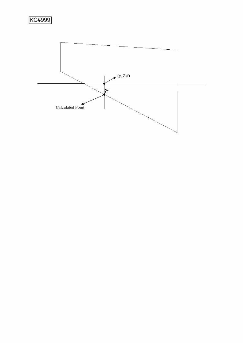
999attc 8/4.2.3.4 Question
Calculationof stress due
to liquidpressure
With respect to Ch.8 Sec.4 [2.3.4]1. Please specify the definition of the tank top longitudinals in the sentence “…no inertial pressure is considered for the tank top longitudinals…”.2. When calculate the inertial liquid pressure pBW,ij(k),SF for full-filled tank orhalf-filled tanker, the coordinates of the calculation point taken at the liquidsurface should be clarified.
A1 "the tank top longitudinals" in Ch.8/Sec.4/[2.3.4] mean the longitudinals onthe top structure of the tank.
A2 For the half-filled tanker, when calculating the inertial liquid pressurepBW,ij(k), z=z_SF, y=y coordinate of the calculation point of the longitudinalstiffener.xB, yB and zB are considered in A4 of KC #359
Y
Page 10 of 10

Gil-Yong Han
From: Johnston, Alex [[email protected]]
Sent: 08 January 2007 12:20
To: Johnston, Alex
Subject: FW: CSR-BC Relative displacement of transverse bulkhead
Page 1 of 4
09/01/2007
1. Could you forward our question below to IACS PT with respect to JBP Ch 8 Sec 4 2.3.6 for fatigue analysis of longitudinals in way of T.BHD.
2. Relative displacement _A, _F;
Example displacement in alternate condition is shown below with undeformed shape. We have considered how to treat this relative displacement and some ideas are illustrated. Could you confirm which interpretation (Case 1 ~ 3) is correct? 2.1. On bottom shell;
Case 1 Measured in global Z coordinate (vertical direction);
Case 2; Measured from parallel line at the location considered;
KC#342

Case 3; Measured from parallel line joining intersection of adjacent floors;
2.2. On side shell;
Case 1 Measured in global Y coordinate (transverse direction);
Page 2 of 4
09/01/2007

Case 2 Measured from normal line at the location considered;However, it seems difficult to make the normal line as there are no connecting point such as inner bottom as shown above.
Case 3 Measured from parallel line joining intersection of adjacent transverse webs;
Page 3 of 4
09/01/2007

3. This interpretation is urgently requested .
We very much appreciate your kind support,
Best Regards,
A Fukushima Surveyor Hull Structures Group Yokohama Design Support & Plan Approval Department (YDSPAD) Lloyd’s Register Asia Tel No. +81 (0) 45 682 5270 Fax No. +81 (0) 45 682 5279
Page 4 of 4
09/01/2007

COMMON STRUCTURAL RULES FOR BULK CARRIERS
Stress concentration factor for the hatch corners
Doubts in the CSR bulk formula (Kgh)
COMMON STRUCTURAL RULES FOR BULK CARRIERS
Chapter 8 - Fatigue check of structural details
Section 5 – STRESS ASSESSMENT OF HATCH CORNERS
KC#385

Correction factor for elliptic corners In the bulk formula, ra is used for rounded corners (the radius in major axis) as a basis for elliptic corners. They attribute a correction factor to take into account the influence of elliptic shape.Here is the equivalence between the two shapes:
with the following correction factor to apply to get the elliptic stress concentration factor from the rounded one:
Here follow the original text describing the correction factor:
This correction factor gives the ratio of stress concentration for the tension of an infinite width thin element with an elliptic hole to that with a circular hole. In this equation, ar denotesthe radius in major axis and br denotes the radius in minor axis. This correction factor can be
applied to the stress concentration factor for the fillet shoulder with circular arc shape of radius ar .
We test the correction factor with ANSYS 9.0 finite element software. We used shell elements of 10 mm thickness. We model plates of 2 by 6 meters with holes in the middle and impose displacements of 20 mm in the small direction as shown in the figure below. We use a 206000 MPa Young modulus and a 0.3 Poisson ratio.
We compare six different shapes to the circular one.
10 mm
10 mm
2000 mm
2 ra
2 rb ra
a
bc r
rf32
31

Dimensions of the compared ellipses Shape Arm length in x axis Arm length in y axis Circular hole 200 200Ellipse 1 50 200Ellipse 2 75 200Ellipse 3 100 200Ellipse 4 200 250 Ellipse 5 200 300 Ellipse 6 200 400
Ellipse shapes 4, 5 and 6 are other kind of ellipse shape that those used for bulk formula. The reference axis is the minor one.
Measures
Mean stress
The mean stress is calculated as follow for a simple tensile test without any hole:
MPa
E
mean
mean
206001.0
Maximum stress
This is the greatest principal stress read in the model as shown on the following pictures.
2 rb
2 rbra
xy
2 ra
2 rb ra
Ellipse shape based on major axis (bulk
Ellipse shape based on minor

ANSYS 9.0 tests
Rounded corner Sig max = 5731 MPa
Elliptic corner (200x300) Sig max = 4386 MPa

Models used
Elliptic corner (75x200) Sig max = 3538 MPa

Results
Comparison between Kt eval (fc) and Kt real (ANSYS software) for the different ellipses Shape dimensions Maximum
stressKt real (Max stress/2060)
Correctionfactor fc
Kt evaluated (2.78* fc)
Kt eval /Kt real
Circular hole 200x200 5731 2.78 1 Ellipse 1 50x200 3057 1.48 0.5 1.39 0.94Ellipse 2 75x200 3538 1.72 0.58 1.62 0.94Ellipse 3 100x200 4009 1.95 0.67 1.85 0.95Ellipse 4 200x250 4928 2.39 0.87 2.42 1.01Ellipse 5 200x300 4386 2.13 0.78 2.17 1.02Ellipse 6 200x400 3702 1.8 0.67 1.85 1.03
We can see that rb radius is a more conservative basis than ra to evaluate the influence of an elliptic shape. The error is a bit less than for ra and the Kt obtained is over evaluated (rbbasis) instead of being under evaluated (ra).
2 rb
2 rbra
xy
2 ra
2 rb ra
Ellipse shape based on major axis (bulk
Ellipse shape based on minor
1
Stress Concentration around Hatch Corner of Bulk Carrier
1 Simplified Fillet Shoulder Model of Hatch Corner
When evaluating a stress concentration around hatch corner of bulk carrier subject to the longitudinal stress due to vertical hull girder bending moment, that is illustrated in Fig.1(a), the shaded area in cross deck is the area where the longitudinal stress is not worked. Therefore, in order to evaluate the stress concentration around hatch corner of bulk carrier, the simplified fillet shoulder model shown in Fig.1(b) can be used.
The height of fillet shoulder depend on the degree of disturbance of longitudinal stress flow occurred due to the structural discontinuity around hatch corner.
Fig. 1(a) Hatch Opening of Bulk Carrier Fig. 1(b) Simplified Fillet Shoulder Model
2 Stress Concentration Factor 2.1 Experimental Formula
The stress concentration factor for the stepped flat tension bar with fillet shoulder was given by Heywood [ Heywood, R. B., “Photo-elasticity for Designers”, Pergamon, New York, 1969 ] as below.
65.065.065.0
2tan
8.0tan8.21
8.06.51
228.21
rL
bLb
rh
bhb
rbH
bHb
The above formula can be applied in evaluating the stress concentration factor to the nominal hull girder vertical bending stress which acts on the ship’s side part of upper deck. The above formula gives the stress concentration factor for the hatch corner of circular arc shape. Although an elliptic arc shape is often used to decrease stress concentration in the actual design, there are no analytical nor experimental results regarding on the stress concentration for the fillet shoulder with elliptic arc shape.
Here, following simple correction factor for the elliptic arc shape is assumed. This correction factor gives the ratio of stress concentration for the tension of an infinite width thin element with an elliptic hole to that with a circular hole. In this equation, ar denotes the radius in major axis and br denotes the radius in minor axis. This correction factor can be applied to the stress concentration factor for the fillet shoulder with circular arc shape of radius ar .
a
bc r
rf
32
31
L
B
r
b
h
b/2
b/2
L
h
H
KC#386

2
2.2 Disturbance of stress flow
As shown in Fig. 1(a), the disturbance of longitudinal stress flow is occurred at the opening corner due to the structural discontinuity around hatch corner. This disturbance of stress flow causes stress concentration and the degree of stress concentration depends on the angle of disturbed stress flow ‘ ’ and the length of shoulder. According to the
photoelasticity experimental results, it is said that the angle of disturbed stress flow was about 10 to 30 degree. According to the results of FE analysis of bulk carrier made by NK, the angles of disturbed stress flow around hatch corner were about 15 to 30 degree as shown in Table 1.
Table 1 Angle of disturbed stress flow to the longitudinal direction Location Angle to the longl. Direction.
Opening at mid part 16.5 28.9 Foremost opening 23.0
2.3 Shape of Hatch Opening of Bulk Carrier The degree of stress concentration at hatch corner is also depending on the shape of hatch opening on the upper
deck. Table 2 shows the results of the survey of existing bulk carriers. According to the Table 2, the ratio of ‘H’ to ‘b’ is about 1.1 to 1.3. And the ratio of ‘ ar ’ to ‘b’ is about 0.05 to 0.07.
Table 2 Shape of Hatch Opening of Typical Bulk Carriers S. No. Lpp B Length Width L b H(15) H(20) H(25) H(30) major r minor rBC1 179.80 31.00 20.80 17.60 8.00 13.40 15.54 16.31 17.13 18.02 0.90 0.45 BC2 185.00 32.26 20.47 18.60 8.90 13.66 16.04 16.90 17.81 18.80 BC3 215.00 32.20 17.85 14.58 7.65 17.62 19.67 20.40 21.19 22.04 1.22 0.61 BC4 279.00 45.00 16.32 20.16 10.56 24.84 27.67 28.68 29.76 30.94 BC5 279.00 45.00 14.72 21.00 11.04 24.00 26.96 28.02 29.15 30.37 1.36 0.78 BC6 279.20 45.00 15.47 20.00 10.01 25.00 27.68 28.64 29.67 30.78 BC7 290.20 50.00 15.76 23.40 10.84 26.60 29.50 30.54 31.65 32.86
2.4 Examples of Stress Concentration Factor Figure 2(a) and 2(b) show the results of evaluated stress concentration factor for the hatch corner where a circular
arc shape and an elliptic arc shape are applied respectively. In these figures, brx a and bHp .
When an elliptic arc shape is applied to the hatch corner, the stress concentration becomes sufficiently small.
Fig. 2(a) Stress Concentration Factor when the Corner is Circular Arc Shape
1 1.05 1.1 1.15 1.2 1.25 1.3p
1.25
1.5
1.75
2
2.25
2.5
0.05 0.06 0.07 0.08 0.09 0.1x
1.25
1.5
1.75
2
2.25
2.5
x=0.05
x=0.06
x=0.07p=1.1
p=1.3
p=1.2

3
Fig. 2(b) Stress Concentration Factor when the Corner is Elliptic Arc Shape
3 Proposed Formula of Stress Concentration Factor The stress concentration factor for the hatch corner is proposed as below.
65.022.0
8.023.11
32
,0.1maxaa
ba
rL
bLb
rrr
where ar ; radius in major axis
br ; radius in minor axis ( if the shape of corner is a circular arc, br is to be equal to ar )
L ; length of cross deck b ; distance from the edge of hatch opening to the ship’s side
1 1.05 1.1 1.15 1.2 1.25 1.3p
1.2
1.4
1.6
1.8
0.05 0.06 0.07 0.08 0.09 0.1x
1.2
1.4
1.6
1.8
x=0.05
x=0.06
x=0.07
p=1.1
p=1.3
p=1.2

�� ����������� ������ ������������������ �������������������������� �����������������
������ ����������� �������������������������������������������� ������������������������������������������������� �����������������������
�������������������������������������������������������� ����������������!���"�
� ���������� �������������� ���������������!����� �������������������������� ��������������������������������
���
����������������!��� � � � � � � � � � � � � � � � � � �������"� � � � � � � � � � � � � � � � � � #���� ��� � � � � � � � � � � � � � � � � � � � � � � � � � �� � � � � � � � � � � � � � � � � � � � � � � � � � � � � � �� � � � � � � � � � � � � � � � � � � � � � � � � � � � � � � � � � � � � � � � $�� �������������� � � � � � � � � � � � � � � � � � � � � � � � � � � � � � � � � � � � � � � � � � � � � � � � � � � � � � � � � � � � � � � � � � � � � � � � � � � � � � � � � � ���� � � � � � � � � � � � � � � � � � ����������!��� � � � � � � � � � � � � � � � � � � � ��!����"�
�������
KC#603

%� ������������������ ������ ������������������ �������������������������� �����������������
������ ����������� ������!����� �������������������������� �������������������������������������������� �����������������������&������
����������������!��%"�� ���������� �������������� ���������������!����� ���������������������
����� ������������������������������������ � � � � � � � � � � � � � � � � � � � � � � � � � � � � $�� ����������������� � � � � � � � � � � � � � � � � � � � � � � � � � � � � � � � � � � � � � ������������
�����������

KC#635

Page 1 of 1
KC Question ID 742, 28 April 2008 (from LR)
The members and locations subjected to fatigue analysis are described in Table 1 of Ch 8,Section 1 of CSR bulk carrier Rule (see below table). Could you please clarify following queries:-
Members Details Connection with sloping and/or vertical plate of lower stool Inner bottom plating Connection with sloping plate of hopper tank
Inner side plating Connection with sloping plate of hopper tank Connection with sloping plate of lower stool Transverse bulkhead Connection with sloping plate of upper stool
Hold frames of single side bulk carriers
Connection to the upper and lower wing tank
Connection of longitudinal stiffeners with web frames and transverse bulkhead
Ordinary stiffeners in double side space
Connection of transverse stiffeners with stringer or similar Ordinary stiffeners in upper and lower wing tank
Connection of longitudinal stiffeners with web frames and transverse bulkhead
Ordinary stiffeners in double bottom
Connection of longitudinal stiffeners with floors in way of transverse bulkhead
Hatch corners Free edge of hatch corners
(1) The fatigue performance of members and loactions in red font in above table need to be evaluated using very fine mesh FE model, the other parts can be evaluated using simplified method.
For very fine mesh analysis, which cargo hold should be done? Heavy ballast hold, Heavy cargo hold or Light cargo hold?
(2) The transverse BHD connection with sloping lower stool and upper stool should be checked, but how about transverse BHD connection with vertical lower stool and upper stool? Should it be checked as well or just ignored it?
(3) Which locations should be checked, for example:-
(3-1)Inner bottom plating/connection with sloping and/or vertical plate of lower stool Centreline or full breath?
(3-2)Inner bottom plating/ Connection with sloping plate of hopper tank Mid-hold or full length of hold?
(3-3)Inner side plating/ Connection with sloping plate of hopper tank Mid-hold or full length of hold?
(3-4)Transverse bulkhead/ Connection with sloping plate of lower stool Centreline or full breath?
(3-5)Transverse bulkhead/ Connection with sloping plate of upper stool Centreline or full breath?
(3-6) Hold frames of single side bulk carriers/ Connection to the upper and lower wing tank Mid-hold or full length of hold?
END
KC#742

CSR KC ID 875, Question
Loading Conditions BC-A BC-B BC-C
Homogeneous 0.6 0.7 L<200m Alternate 0.1 --- Normal ballast 0.3 0.3
Homogeneous 0.25 0.5 L 200m Alternate 0.25 --- Normal ballast 0.5 0.5
KC#875
Calculated Point
(y, Zsf)
KC#999


![Bulker Q&As and CIs on the IACS CSR Knowledge Centre KCID ... · Appendix 1, [2.2.8], please refer to the file attachement "Draft Answer Ch 5, App 1, [2.2.8].doc". Also Included in](https://img.pdfslide.net/doc/110x75/5f9de6169c6ce326b074c6b3/bulker-qas-and-cis-on-the-iacs-csr-knowledge-centre-kcid-appendix-1-228.jpg)


![Bulker Q&As and CIs on the IACS CSR Knowledge …According to Ch4, Sec5, [1.1.1] external sea pressure is defined as summation of hydrostatic pressure and hydrodynamic pressure but](https://img.pdfslide.net/doc/110x75/5e876f88e80f526ffa22e27e/bulker-qas-and-cis-on-the-iacs-csr-knowledge-according-to-ch4-sec5-111.jpg)


![Iacs Standard[1]](https://img.pdfslide.net/doc/110x75/54774576b4af9f76108b46d1/iacs-standard1.jpg)