Embed Size (px)
Citation preview

BULLET ELECTRA - EFI

BULLET ELECTRA EFI ServicePrecautions

ENGINE SPECIFICATIONS
MAKE:
MODEL:
Type 4 Stroke
DETAILS ROYAL ENFIELD
UCE-500 E.F.I
ENGINE:
84
Stroke Length (mm) 90
Eng. Displacement (CC) 499
Bore Dia. (mm)
Comp. Ratio 8.5:1
Engine cooling Natural Air Draft
Engine Alignment Vertical
Valve train OHV, PUSH ROD actuated
No. of valves/cyl. 2
No. of cylinders 1
Idle speed (rpm) 1000±100
Ign. Timing (Deg. BTDC) 5º Static
Engine Lubricating oil grade 15W50 API SL Grade
Engine oil quantity (Liters) 2.75
Spark plug Grade BOSCH SUPER WR3CC
Spark plug Electrode air gap (mm) 0.7

General Service PrecautionsCHASIS SPECIFICATIONS
Front
Rear
Front- Solo
Front- With Pillion
Rear- Solo
Rear- With Pillion
CHASSIS:
TYPE Tubular frame, Engine as stressed member
Tyre size (W X DIA)"90/90
100/90
Tyre Air pressure (Psi)
18
20
28
30
VEHICLE: MOTOR CYCLE- CRUISER
Fuel tank capacity (Liters) 14.5 ± 1.0
Kerb Wt (kgs) 180
Gross Wt (kgs) 365
Length (mm) 2200
Width (mm) 790
Height (mm) 1100
Wheel base (mm) 1370
Saddle height (mm) 820
Ground clearance (mm) 140

General Service PrecautionsELECTRICAL SPECIFICATIONS
For Battery
RR unit
ECU
FUSE ratting15 A
15 A
15 A
Low fuel Indicator 1.7 W
Alternator capacity 220 Watts at 5000 rpm
Starter Motor 0.9 KW
Mal-function Indicator (M.I.L) 3.4 W
Neutral Indicator 12V, 2 W- 1no.
Horn 12V, 2.5 Amp (Max.)
High beam indicator 12V, 2 W- 1 no.
Turn signal 12V, 10 W- 2+2 nos.
Speedometer lamp 12V, 3.4W- 1 no.
Turn signal 12V, 2 W- 1 no.
Tail / Brake lamp 12V, 5/21 W
Pilot lamp 12V, 2 W- 3 nos.
Batter capacity 12V, 14AH
Head Lamp 12V, 60/55 W
ELECTRICAL SYSTEM:
System spec. 12V, DC

UNIT CONSTRUCTION ENGINE – 500 cc - EFI
View I

View II

View III

View IV

ARCHITECTURE UCE 500 EFI ENGINE(AS COMPARED TO EXISTING LB 500)
# DESCRIPTION LB 500 cc ENGINE UCE 500 cc ENGINE
1 Configuration Engine, gear box and
clutch are separate
compartment.
Engine, gear box and
clutch are being
made as integral
construction.
2 Oil Sump
system
Dry sump lubrication
systemWet sump
lubrication system

3 Oil pump Design Gear pump design. Oil
flow rate is 2.42 L/mt
@ 5500 engine rpm.
Gerotor - rotary
type oil pump. Flow
rate : 9.5 L/ mt @
5500 engine rpm. It
provides better oil
flow and cooling to
the engine.
4 Combustion
chamber and
port design
Wedge type
combustion chamber
with high turbulence.
Wedge type
combustion chamber
with high turbulence.

5 Piston design Solid skirt piston with flat
crown made up of high
silicon alum Alloy.
Solid skirt piston with bowled
crown made up of high silicon
alum Alloy for better combustion
6 Cylinder barrel Cylinder barrel is made
up of Aluminium with
cast iron liner
Cylinder barrel is made up of
Aluminium with cast iron liner
7 Piston ring
pack
Modular, robust, thick
piston ring pack to
control oil consumption
Modular, Flexible thin piston ring
pack to reduce friction and blow
by thereby better performance

8 Tappet The tappet is sursulf
coated after heat
treatment.
Hydraulic tappet is used.
It helps to maintain zero
clearance of pushrod at
all engine operating
conditions enabling
uniform valve timing
9 cam gear - inlet Cam gear gets
assembled in eccentric
sleeve with spindle
assy. It is to adjust the
centre distance and
hence backlash gets
adjusted.
Anti back lash gear
system is used to arrest
the back lash between
inlet and exhaust cam
gears.

10 Engine
breathing
system
Higher engine
crankcase pressure
and hence separate
breather box is
provided to collect the
breather oil
Lesser crankcase
breather pressure due to
integration of engine with
gear box and clutch
compartment. Oil
deflector arrangement
has been provided inside
the engine cover to
prevent oil mist coming
out.

11 Decompressor
design
Actuated through valve
train leads to
mechanical losses and
hence inferior
functioning
Auto decompressor
design activate at 250
rpm and will get fully
deactivated at 350 rpm
12 Primary chain
adjuster
Mechanical type chain
tensioner is used to
adjust the primary
chain.
Auto chain tensioner
( Rack type ) is used
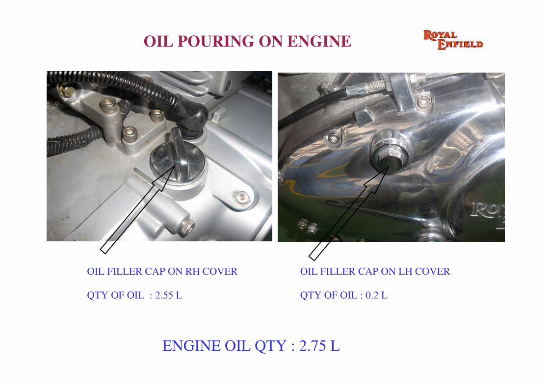
OIL POURING ON ENGINE
OIL FILLER CAP ON RH COVER
QTY OF OIL : 2.55 L
OIL FILLER CAP ON LH COVER
QTY OF OIL : 0.2 L
ENGINE OIL QTY : 2.75 L

OIL DRAIN PLUG WITH
INBUILD MAGNET
OIL DRAINING

OIL LEVEL WINDOW
� Place motorcycle on its center stand on a firm surface.
� Warm up engine for 2-3 minutes & switch off before checking oil level.
� The level is corrected if the oil level is in the middle of the oil level window.
� Top up with oil if required.

EFI BLOCK DIAGRAM

The main system in EFI is the computercalled ECU (Engine Control Unit). Thismonitors engine operating parameters bytaking various inputs like engine speed,engine temp, throttle position, manifoldair pressure, exhaust oxygen feed backfrom respective sensors. Based on theinput data, the ECU calculates the idealamount of fuel to be injected to optimizethe air-fuel ratio and also the ignitiontiming for the spark plug.
FUNCTION:

General Service PrecautionsINSTRUCTIONS (DO’’’’S & DON’’’’TS)
•Fully Charged Battery should be connected
•Keep the vehicle on center stand or remove thestand and then start the engine(NOTE: engine will switch OFF if parked on sidestand).
•Switch on the ignition key and wait (for app. 3Sec) until the MIL (MALFUNCTION INDICATORLAMP) glows off, then start the Engine. If MIL stillglows contact the dealer.

General Service Precautions
•Don't remove any of the sensor connections orcouplers
•Don't touch the exhaust bend, O2 sensor andsilencer with bare hand when the engine isrunning or just switched off(NOTE: Catalytic Converter present inside, theexhaust system will be very hot).
•Don't remove the fuel hose (high pressure) fromthe fuel pump to fuel injector, while removeproper care should be taken.

General Service PrecautionsPROBLEMMIL BLINKING CONTINUOUSLY
REMEDY:
Check for all the sensor connections plugged inproperly and then reset the system by the followingprocedure
Switch on both the ignition key and kill switchwait, for 10 sec then completely open the throttle for10 sec, then release the throttle, after 5 sec mil willblink continuously for twice, reset completes. Thenswitch off the ignition and switch the ignition keywait for 3 sec then start the engine. (note duringreset procedure the engine should not be started,only the ign. Key and kill switch is to be turned on.)

General Service Precautions
ENGINE NOT STARTING:
Check for the side parking stand is on, if soremove the side parking stand and also check forthe sensor connections plugged in properly, thenreset the system by the above procedure

General Service Precautions
• Before attempting to remove any part, turn theignition switch “OFF” and disconnect the batteryground cable.
• Always use a 12 volt battery as a power source,never use a booster or high voltage chargingunit.
• Do not disconnect the battery cables when theengine is running.
• Do not un-plug any wiring connectors with theengine running or the ignition “ON” unlessspecifically instructed to do so.
GENERAL INSTRUCTIONS:

General Service Precautions• Keep open flame out of workshop area.
• Use a shop towel to hold fuel when opening thefuel system.
• Always keep fire extinguisher in the workshop.
• Always use eye or full face protection whenworking around fuel lines.
• Do not rev-up the engine immediately afterstarting or just prior to shut down.
• Keep all ECU parts and harness dry during service.Protect the ECU and its related solid-statecomponents from rough handling or extremetemperature.

LOCATION OF EFI COMPONENTS IN THE VEHICLE

ELECTRONIC CONTROL UNIT
ELECTRONIC CONTROL UNIT

FUEL SYSTEM
FUEL PUMP MODULE LOW LEVEL SENSOR

General Service Precautions
INLET MANIFOLD ASSEMBLY
FUEL INJECTOR
INLET MANIFOLD

General Service PrecautionsTHROTTLE BODY ASSEMBLY
THROTTLE BODY

General Service Precautions
EXHAUST SYSTEM
LAMBDA (O2) SENSOR & CATALYTIC CONVERTOR
CATALYTIC CONVERTORLAMBDA SENSOR

General Service Precautions
WARNING SYSTEM INDICATOR
SPEEDOMETER LOW FUEL WARNING MALFUNCTION
WARNING

General Service Precautions
IGNITION KEY KILL SWITCH
IG KEY FOR START & STOP