Embed Size (px)
Citation preview
Bundesanstalt für StraßenwesenBundesanstalt für Straßenwesen(Federal Highway Research Institute)
Proposal for a Modification of the
Lower/Upper Legform to Bumper Test Area
in GTR9-PH 2
and UN-R 127 01 Series of Amendments
Bundesanstalt für Straßenwesen(Federal Highway Research Institute)
6th Meeting of Task Force Bumper Test Area (TF-BTA)Paris, May 15th, 2014
Oliver Zander, Marcus WischBundesanstalt für Straßenwesen
Dirk-Uwe GehringBGS Boehme & Gehring GmbH
TF-BTA-6-07
• TF-BTA started in March 2012
• Focus: revision of the bumper test area to counteract manufacturer‘spractice of narrowing the bumper test area by any design means
• At the constitutional meeting of TF-BTA, the German Federal Ministry of Transport and Digital Infrastructure (BMVI) handed in a document from BASt, explaining about the history of the BTA definition and making an optional proposal for an alternative bumper test area:
Background
Option 1:
Introduction of the test area according to Euro NCAP
Option 2:
Use of whole vehicle width
Oliver Zander Slide No. 2May 15th, 2014
TF-BTA-6-07
Current GTR9 Definitions
Oliver Zander Slide No. 3May 15th, 2014
[…]
TF-BTA-6-07
Current GTR9 Definitions (cont‘d)
[…]
[…]
Oliver Zander Slide No. 4May 15th, 2014
TF-BTA-6-07

Option 1: Introduction of the test area according to Euro NCAP
BASt Option 1
“The bumper test zone is defined
as either the area limited by the
bumper corners or the outermost
ends of the bumper beam/lower
rails/cross beam structures,
whichever is larger. “
���� max (bumper beam width, bumper corner area)
Oliver Zander Slide No. 5May 15th, 2014
TF-BTA-6-07
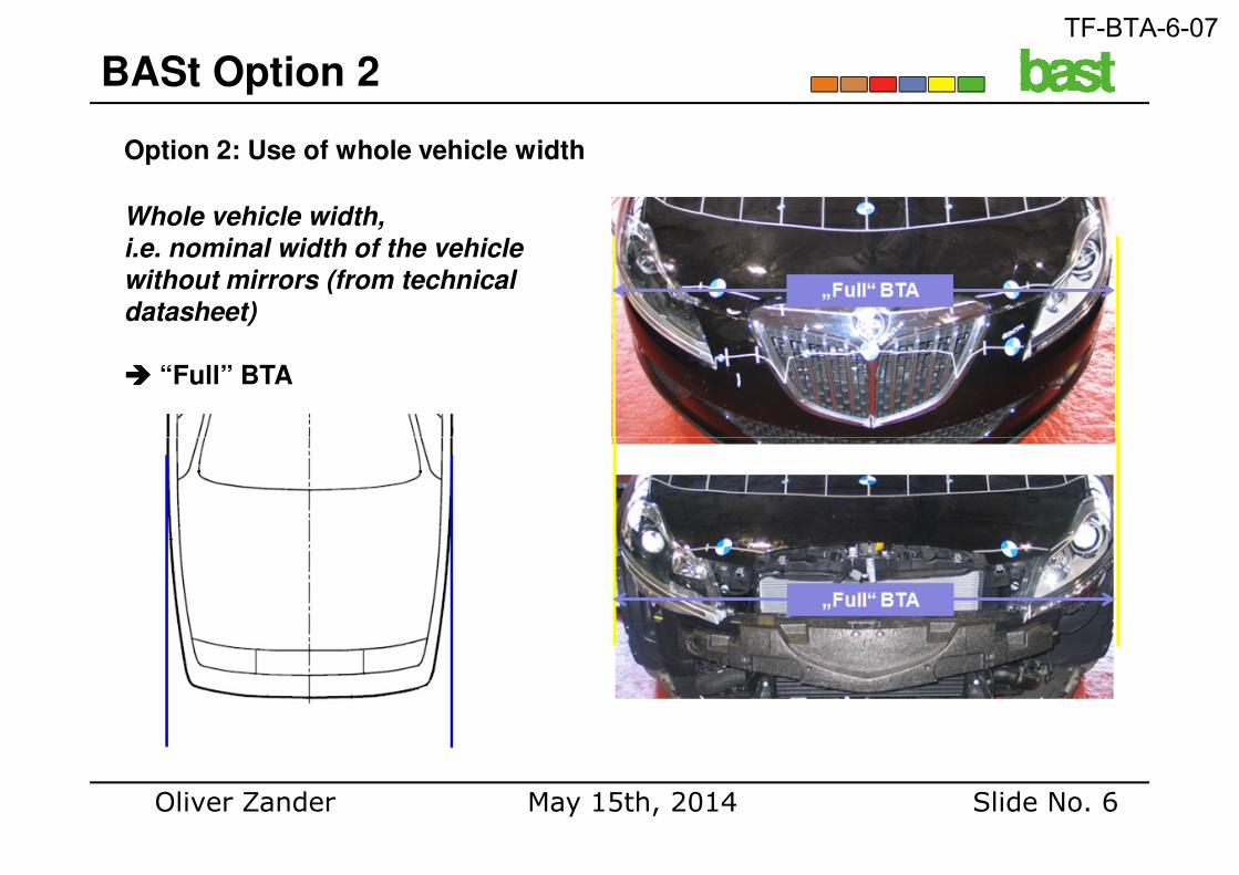
Option 2: Use of whole vehicle width
BASt Option 2
Whole vehicle width,
i.e. nominal width of the vehicle
without mirrors (from technical
datasheet)
���� “Full” BTA
Oliver Zander Slide No. 6May 15th, 2014
TF-BTA-6-07
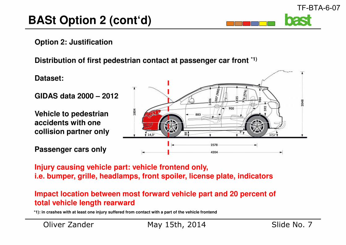
Option 2: Justification
BASt Option 2 (cont‘d)
Distribution of first pedestrian contact at passenger car front *1)
Dataset:
GIDAS data 2000 – 2012
Vehicle to pedestrianaccidents with one
Oliver Zander Slide No. 7May 15th, 2014
accidents with onecollision partner only
Passenger cars only
Injury causing vehicle part: vehicle frontend only, i.e. bumper, grille, headlamps, front spoiler, license plate, indicators
Impact location between most forward vehicle part and 20 percent oftotal vehicle length rearward*1): in crashes with at least one injury suffered from contact with a part of the vehicle frontend
TF-BTA-6-07
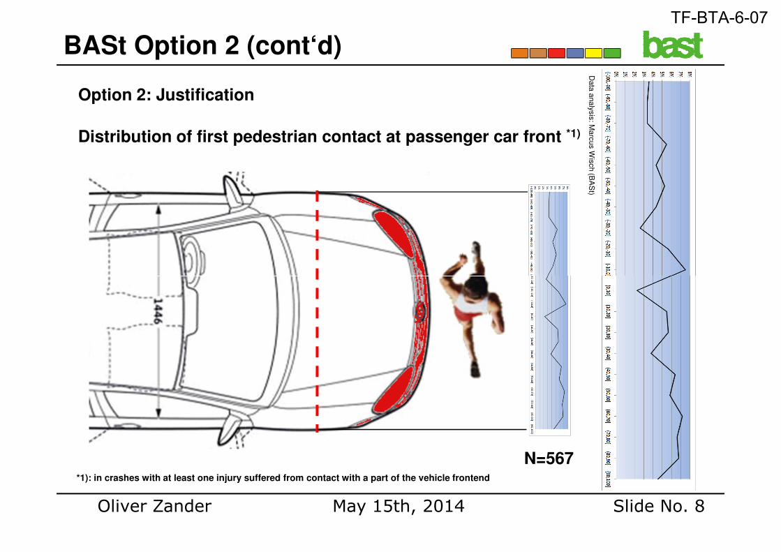
Option 2: Justification
BASt Option 2 (cont‘d)
Distribution of first pedestrian contact at passenger car front *1)
Data
analy
sis
: Marc
us W
isch (B
AS
t)
Oliver Zander Slide No. 8May 15th, 2014
*1): in crashes with at least one injury suffered from contact with a part of the vehicle frontend
N=567
TF-BTA-6-07
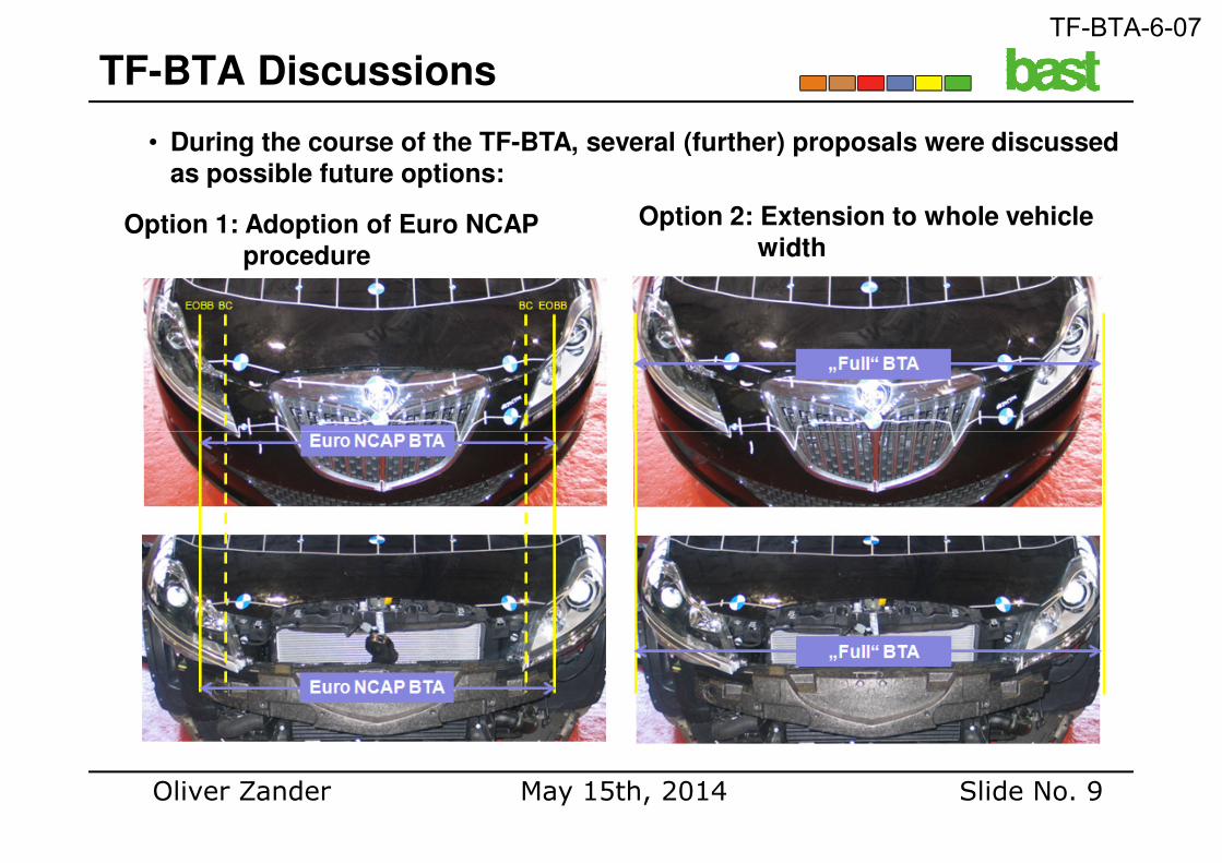
• During the course of the TF-BTA, several (further) proposals were discussed as possible future options:
TF-BTA Discussions
Option 1: Adoption of Euro NCAP procedure
Option 2: Extension to whole vehicle width
Oliver Zander Slide No. 9May 15th, 2014
TF-BTA-6-07
TF-BTA Discussions (cont‘d)
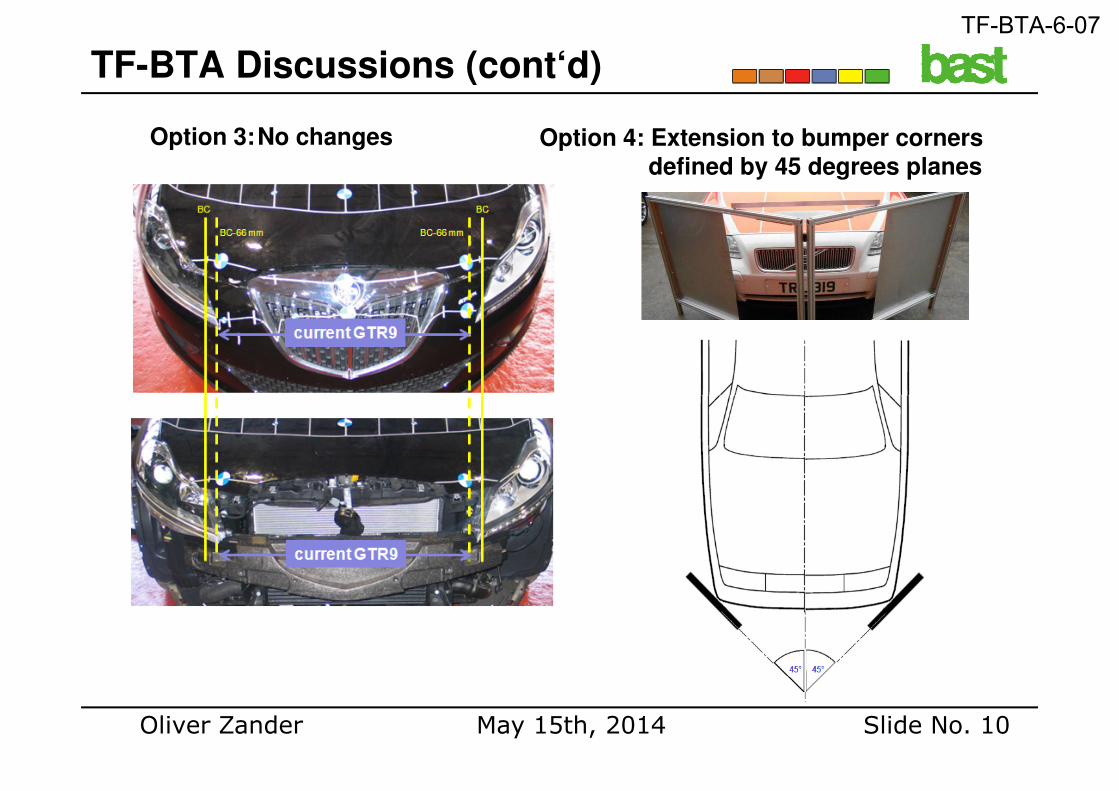
Option 3:No changes Option 4: Extension to bumper corners defined by 45 degrees planes
Oliver Zander Slide No. 10May 15th, 2014
TF-BTA-6-07
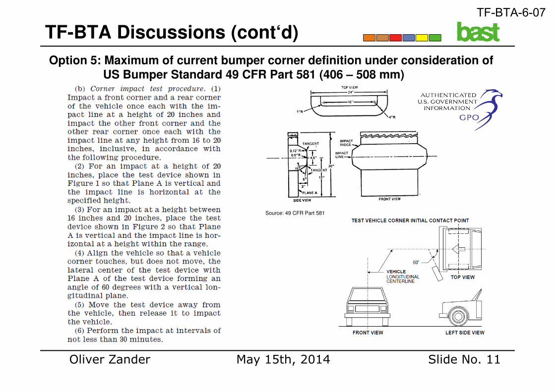
Option 5: Maximum of current bumper corner definition under consideration of US Bumper Standard 49 CFR Part 581 (406 – 508 mm)
TF-BTA Discussions (cont‘d)
Oliver Zander Slide No. 11May 15th, 2014
Source: 49 CFR Part 581
TF-BTA-6-07
• In the end, two proposals are made by Industry and the European Commission:
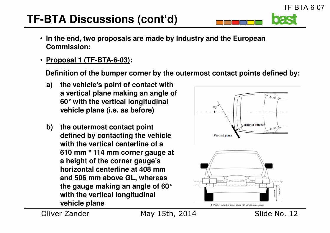
• Proposal 1 (TF-BTA-6-03):
Definition of the bumper corner by the outermost contact points defined by:
TF-BTA Discussions (cont‘d)
a) the vehicle’s point of contact with a vertical plane making an angle of 60°with the vertical longitudinal vehicle plane (i.e. as before)
Oliver Zander Slide No. 12May 15th, 2014
b) the outermost contact point defined by contacting the vehicle with the vertical centerline of a 610 mm * 114 mm corner gauge at a height of the corner gauge’s horizontal centerline at 408 mm and 506 mm above GL, whereas the gauge making an angle of 60°with the vertical longitudinal vehicle plane
TF-BTA-6-07
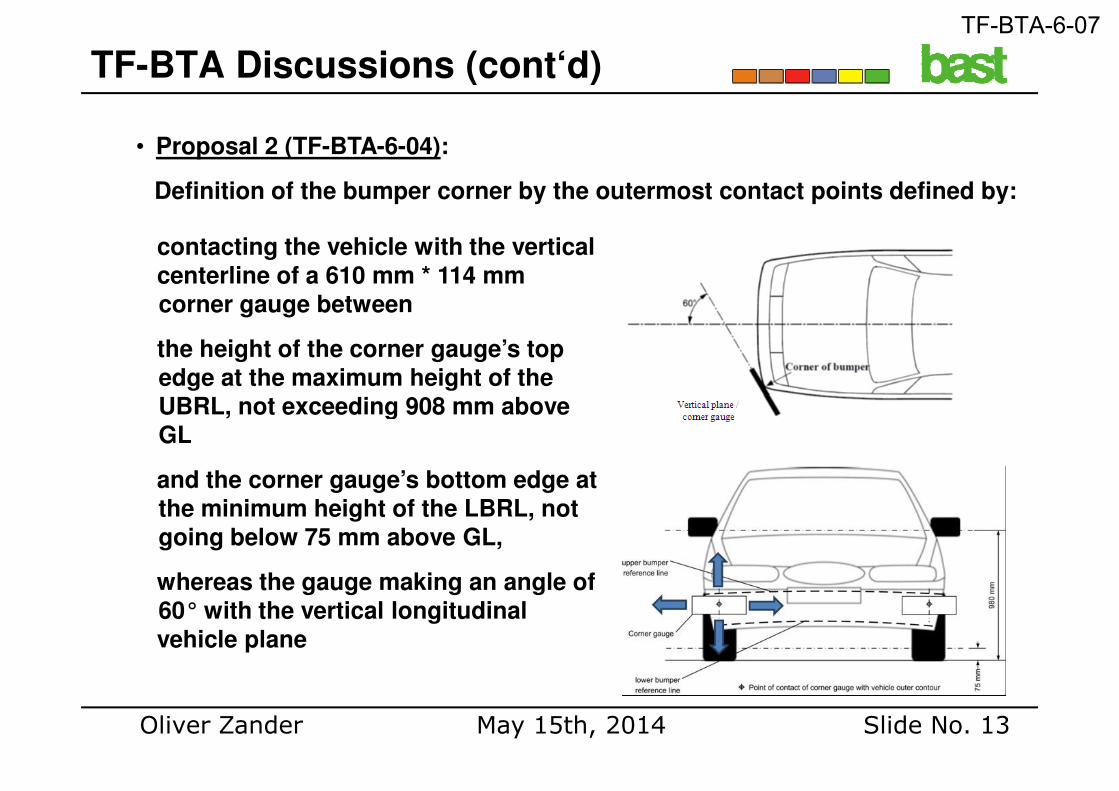
• Proposal 2 (TF-BTA-6-04):
Definition of the bumper corner by the outermost contact points defined by:
TF-BTA Discussions (cont‘d)
contacting the vehicle with the verticalcenterline of a 610 mm * 114 mm corner gauge between
the height of the corner gauge’s top edge at the maximum height of the UBRL, not exceeding 908 mm above
Oliver Zander Slide No. 13May 15th, 2014
UBRL, not exceeding 908 mm above GL
and the corner gauge’s bottom edge at the minimum height of the LBRL, not going below 75 mm above GL,
whereas the gauge making an angle of 60° with the vertical longitudinal vehicle plane
TF-BTA-6-07
• While both proposals are adopting essential elements of the test area definition as described within the US Bumper Standard 49 CFR Part 581 / UN-R 42, BASt was and still is in favour of at least taking over the Euro NCAP procedure.
• Reasons:
1. Injurious points have been continuously found outside the current test area, especially at the ends of the bumper beam.
2. Proposal 2 (TF-BTA-6-04) does not work.
Analysis of Proposals
3. The bumper definition according to the US Bumper Standard / Proposal 1 (TF-BTA-6-03) does not always cover the entire bumper beam.
4. The bumper definition according to the US Bumper Standard / Proposal 1 (TF-BTA-6-03) remains not being robust against any vehicle (outer) design measures.
5. When taking over the explicit RCAR definition of the bumper beam, the Euro NCAP procedure is robust also for legislation.
6. The RCAR definition of a bumper beam is widely accepted.
Oliver Zander Slide No. 14May 15th, 2014
TF-BTA-6-07
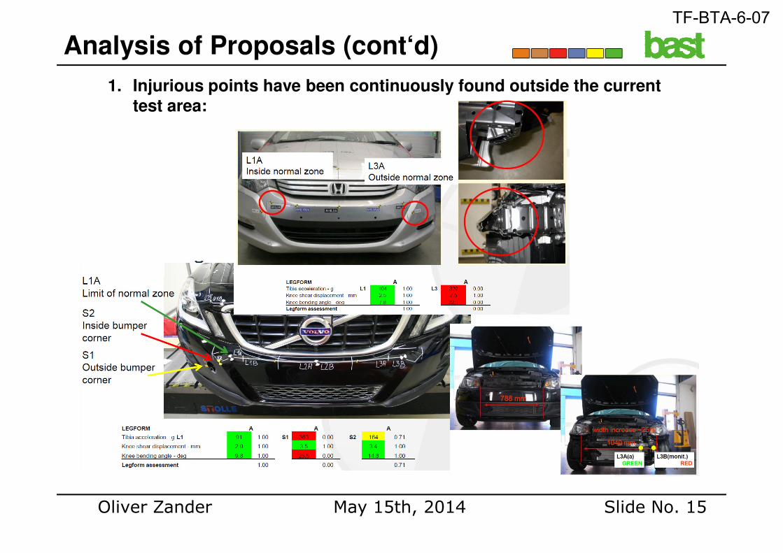
1. Injurious points have been continuously found outside the current test area:
Analysis of Proposals (cont‘d)
Oliver Zander Slide No. 15May 15th, 2014
TF-BTA-6-07
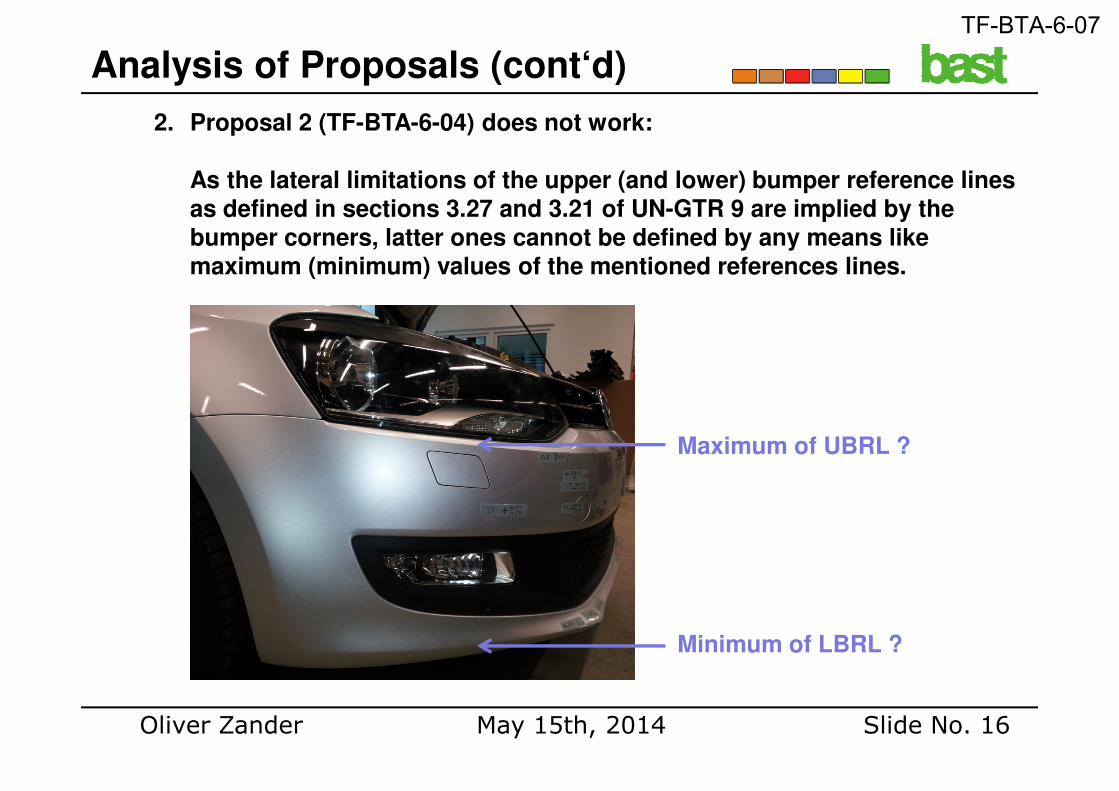
2. Proposal 2 (TF-BTA-6-04) does not work:
As the lateral limitations of the upper (and lower) bumper reference lines as defined in sections 3.27 and 3.21 of UN-GTR 9 are implied by the bumper corners, latter ones cannot be defined by any means like maximum (minimum) values of the mentioned references lines.
Analysis of Proposals (cont‘d)
Oliver Zander Slide No. 16May 15th, 2014
Maximum of UBRL ?
Minimum of LBRL ?
TF-BTA-6-07
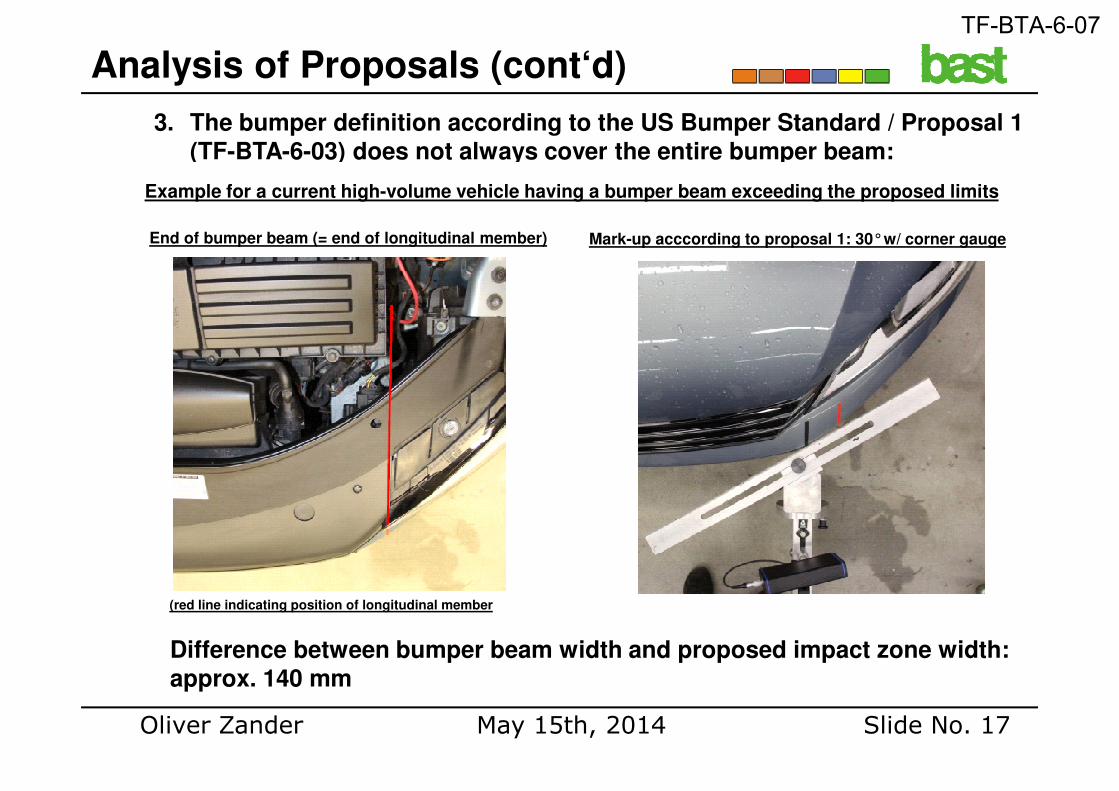
3. The bumper definition according to the US Bumper Standard / Proposal 1 (TF-BTA-6-03) does not always cover the entire bumper beam:
Analysis of Proposals (cont‘d)
Example for a current high-volume vehicle having a bumper beam exceeding the proposed limits
End of bumper beam (= end of longitudinal member) Mark-up acccording to proposal 1: 30°w/ corner gauge
Oliver Zander Slide No. 17May 15th, 2014
(red line indicating position of longitudinal member
Difference between bumper beam width and proposed impact zone width: approx. 140 mm
TF-BTA-6-07
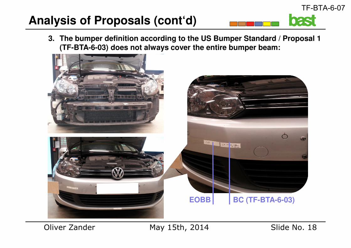
3. The bumper definition according to the US Bumper Standard / Proposal 1 (TF-BTA-6-03) does not always cover the entire bumper beam:
Analysis of Proposals (cont‘d)
Oliver Zander Slide No. 18May 15th, 2014
EOBB BC (TF-BTA-6-03)
TF-BTA-6-07
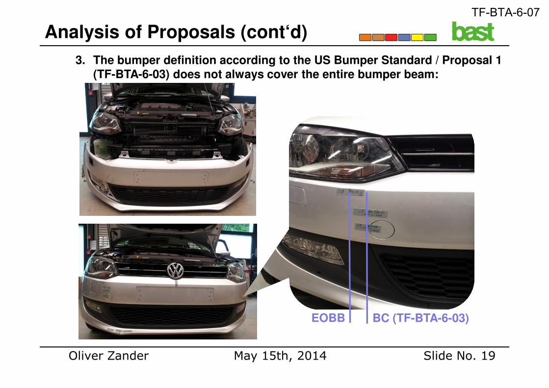
3. The bumper definition according to the US Bumper Standard / Proposal 1 (TF-BTA-6-03) does not always cover the entire bumper beam:
Analysis of Proposals (cont‘d)
Oliver Zander Slide No. 19May 15th, 2014
EOBB BC (TF-BTA-6-03)
TF-BTA-6-07
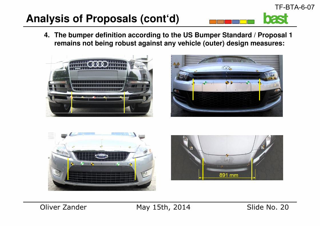
4. The bumper definition according to the US Bumper Standard / Proposal 1 remains not being robust against any vehicle (outer) design measures:
Analysis of Proposals (cont‘d)
Oliver Zander Slide No. 20May 15th, 2014
TF-BTA-6-07
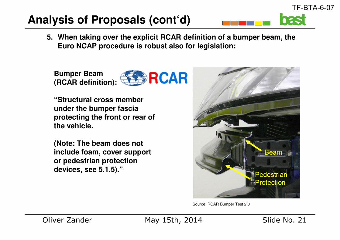
5. When taking over the explicit RCAR definition of a bumper beam, the Euro NCAP procedure is robust also for legislation:
Bumper Beam (RCAR definition):
“Structural cross member under the bumper fascia protecting the front or rear of
Analysis of Proposals (cont‘d)
Oliver Zander Slide No. 21May 15th, 2014
protecting the front or rear of the vehicle.
(Note: The beam does not include foam, cover support or pedestrian protection devices, see 5.1.5).”
Source: RCAR Bumper Test 2.0
TF-BTA-6-07
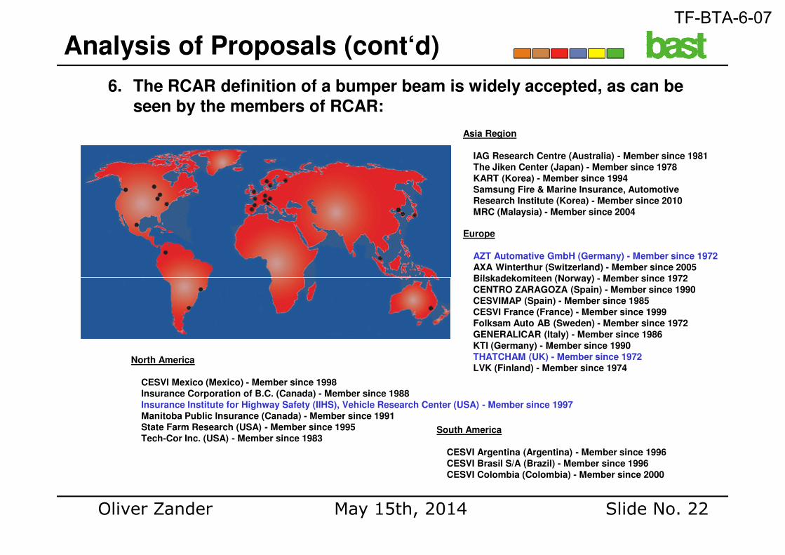
6. The RCAR definition of a bumper beam is widely accepted, as can be seen by the members of RCAR:
Asia Region
IAG Research Centre (Australia) - Member since 1981
The Jiken Center (Japan) - Member since 1978
KART (Korea) - Member since 1994
Samsung Fire & Marine Insurance, Automotive
Research Institute (Korea) - Member since 2010
MRC (Malaysia) - Member since 2004
Europe
AZT Automative GmbH (Germany) - Member since 1972
AXA Winterthur (Switzerland) - Member since 2005
Bilskadekomiteen (Norway) - Member since 1972
Analysis of Proposals (cont‘d)
Oliver Zander Slide No. 22May 15th, 2014
North America
CESVI Mexico (Mexico) - Member since 1998
Insurance Corporation of B.C. (Canada) - Member since 1988
Insurance Institute for Highway Safety (IIHS), Vehicle Research Center (USA) - Member since 1997
Manitoba Public Insurance (Canada) - Member since 1991
State Farm Research (USA) - Member since 1995
Tech-Cor Inc. (USA) - Member since 1983South America
CESVI Argentina (Argentina) - Member since 1996
CESVI Brasil S/A (Brazil) - Member since 1996
CESVI Colombia (Colombia) - Member since 2000
Bilskadekomiteen (Norway) - Member since 1972
CENTRO ZARAGOZA (Spain) - Member since 1990
CESVIMAP (Spain) - Member since 1985
CESVI France (France) - Member since 1999
Folksam Auto AB (Sweden) - Member since 1972
GENERALICAR (Italy) - Member since 1986
KTI (Germany) - Member since 1990
THATCHAM (UK) - Member since 1972
LVK (Finland) - Member since 1974
TF-BTA-6-07
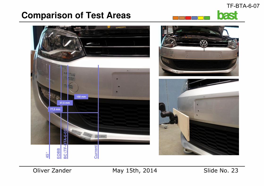
Comparison of Test Areas
Oliver Zander Slide No. 23May 15th, 2014
EO
BB
45
°
BC
(T
F-B
TA
-6-0
3)
Cu
rre
nt
77,5 mm
37,5 mm
150 mm
TF-BTA-6-07
1. In depth accident data gives evidence of an equal distribution offirst pedestrian contact at the front of passenger cars in crashes with at least one injury suffered from contact with a part of the vehicle frontend.
2. Thus, the assessment of injury risks for vulnerable road usersshould be basically done considering the entire vehicle width.
Conclusions
should be basically done considering the entire vehicle width.
3. However, if a limitation of the test area seems necessary due to feasibility reasons for whatever nature, at least no potentially injurious structures should be prematurely excluded from the test area.
Oliver Zander Slide No. 24May 15th, 2014
TF-BTA-6-07
4. Injurious points have been continuously found outside test areas defined by measurements depending on the outer contour, especially at the ends of the bumper beam.
5. Therefore, at least the entire bumper beam should be included within the test area.
Conclusions (cont‘d)
6. Procedures based on the outer vehicle contour do no necessarily include the relevant injurious vehicle structures (bumper beam).
7. There is no evidence for the RCAR definition of the bumper beam not being robust also for legislation.
Oliver Zander Slide No. 25May 15th, 2014
TF-BTA-6-07
BASt Proposal for GTR9 (UN-R 127)
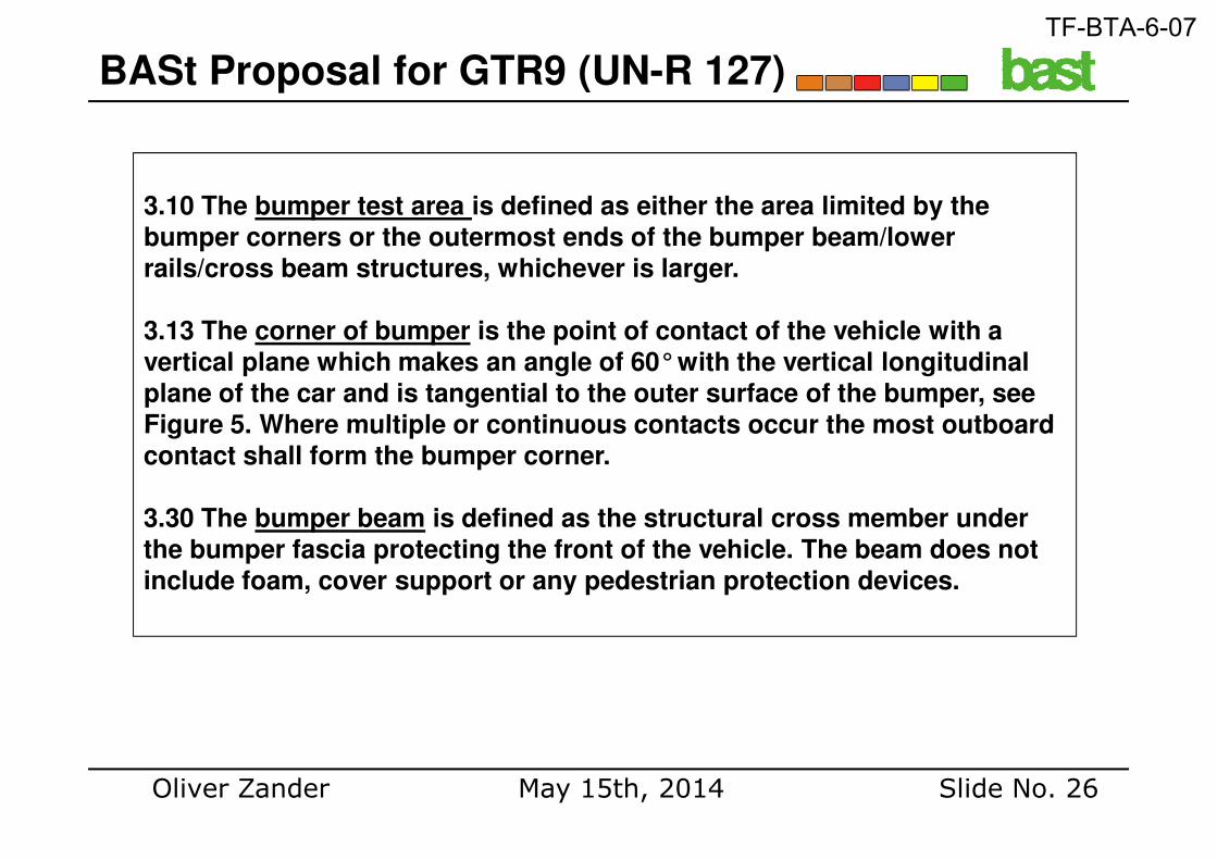
3.10 The bumper test area is defined as either the area limited by the bumper corners or the outermost ends of the bumper beam/lower rails/cross beam structures, whichever is larger.
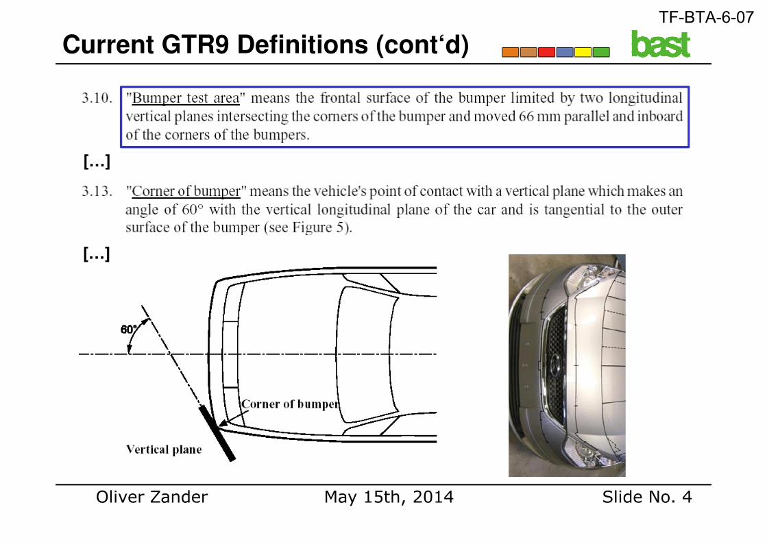
3.13 The corner of bumper is the point of contact of the vehicle with a vertical plane which makes an angle of 60°with the vertical longitudinal plane of the car and is tangential to the outer surface of the bumper, see Figure 5. Where multiple or continuous contacts occur the most outboard
Oliver Zander Slide No. 26May 15th, 2014
Figure 5. Where multiple or continuous contacts occur the most outboard contact shall form the bumper corner.
3.30 The bumper beam is defined as the structural cross member under the bumper fascia protecting the front of the vehicle. The beam does not include foam, cover support or any pedestrian protection devices.
TF-BTA-6-07
Thank you !
Questions ?
Oliver Zander Slide No. 27May 15th, 2014
Questions ?
TF-BTA-6-07