Embed Size (px)
Citation preview

© 2017. Mr. Nicholas Landell-Mills. This is a research/review paper, distributed under the terms of the Creative Commons Attribution-Noncommercial 3.0 Unported License http://creativecommons.org/licenses/by-nc/3.0/), permitting all non commercial use, distribution, and reproduction in any medium, provided the original work is properly cited.
Buoyancy Explains Flight
By Mr. Nicholas Landell-Mills Abstract- Archimedes 2,200 year-old principle of buoyancy can be used to explain the physics of
how planes fly. Specifically, to remain airborne planes must displace a mass of air downwards that is equal to their own mass each second. Key conclusions are that buoyancy applies to moving objects and is measured over a one second time period.
GJSFR-A Classification: FOR Code: 029999
BuoyancyExplainsFlight
Strictly as per the compliance and regulations of :
Global Journal of Science Frontier Research: APhysics and Space ScienceVolume 17 Issue 1 Version 1.0 Year 2017 Type : Double Blind Peer Reviewed International Research JournalPublisher: Global Journals Inc. (USA)Online ISSN: 2249-4626 & Print ISSN: 0975-5896

Buoyancy Explains Flight Mr. Nicholas Landell-Mills
Executive Summary
Abstract-
Archimedes 2,200 year-old principle of buoyancy can be used to explain the physics of how planes fly. Specifically, to remain airborne planes must displace a mass of air downwards that is equal to their own mass each second. Key conclusions are that buoyancy applies to moving objects and is measured over a one second time period.
Buoyancy is consistent with what is observed in
relation to planes in flight and vertical lift:
•
How boats rise up in the water when they go faster. Buoyancy increases as more
water is pushed downwards by the moving boat.
•
How birds and planes both push air downwards during flight.
•
The lift of a wing is proportional to the amount of air that is displaced downwards 8.
•
The critical factors that affect aircraft lift (i.e. velocity, air density, wing angle of attack,
wing area, …) also affect the amount of air displaced downwards by the wing and
thus buoyancy.
•
Buoyancy is consistent with: the dynamics of aircraft flight manoeuvers (such as:
inverted flight, stalls, ground effect, ….), gliders using air currents to gain altitude; the
differences in wing designs; as well as aircraft momentum (speed & weight).
•
In a stable free-fall, at terminal velocity a skydiver will displace a mass of air equal to
their own mass each second.
The current equation for lift:
LIFT=0.5 ( Velocity2
x Air Density x Wing Area x Lift Coefficient)
If the current equation for lift is adjusted to
include “the distance down that air is displaced by
the wing;” then the equation can be re-stated to: LIFT = Mass x Velocity (i.e. F = mv); which is consistent with buoyancy and Newtons 2nd
law of motion.
I.
Introduction
oth planes and birds push air downwards while in flight. The significance of this to how lift
is generated has been mis-interpreted and
overlooked. Buoyancy implies that planes are
just boats with wings.
This new explanation of how planes fly was
developed as the current theories of flight have severe limitations and remain unproven. Pilots, aviation
authorities, academics and engineers still debate different theories of flight. Buoyancy is consistent or compatible with many of the current theories of flight; they’re not necessarily mutually exclusive.
This new explanation of flight has been presented to numerous pilots, engineers and academics. No one has been able to disprove it.
This paper is an update of a previous paper “Buoyancy explains how planes fly,” Dec 2016,
published in the Journal of Aeronautics and Aerospace Engineering.
This paper is mostly theoretical. This explanation of flight could be proved by a empirical
scientific experiment on an aircraft; by measuring the amount of air the wings displace down.
This explanation predicts that for all planes to fly, they must displace a mass of air down equal to its own mass each second.
Explanatory videos of varying lengths titled: “Buoyancy explains how planes fly,” and
“Buoyancy
explains terminal velocity in skydiving,” are available on youtube, on channel of ‘N
Landell’ (the author of this
paper).
Why is this important?
This explanation solves a 100-year-old puzzle as to how planes fly. This theory significantly
changes
the understanding of how planes fly. This will alter how pilots are trained and how
planes are designed; to
achieve better aviation safety and efficiency. This also
explains why fatal aircraft accident rates have not fallen
much since 1990, despite new technology. As
pilots don’t know how the plane flies, they are prone to make fatal errors in a crisis situation.
Buoyancy provides a
much simpler and easier way to understand lift.
II.
Background Information
Keywords:
physics, lift, wing, airfoil, archimedes, buoyancy, plane, fly, aerodynamic.
III.
Method
This work was completed after extensive research, as well as numerous discussions with
academics, engineers, pilots and aviation authorities.
Extensive flying (experimentation) was done on small, single engine aircraft, to test the
validity of the assertions documented in this paper. The findings are consistent with what
pilots experience and the observed aerodynamics when flying a plane.
B
1
Globa
lJo
urna
lof
Scienc
eFr
ontie
rResea
rch
V
olum
eXVII
Issue
e
rsion
IV
IYea
r20
17
35
( A)
© 2017 Global Journals Inc. (US)
Author: MA CFA ACA, British nationality, 75 Chemin Sous Mollards, Argentiere 74400; France. e-mail: [email protected]
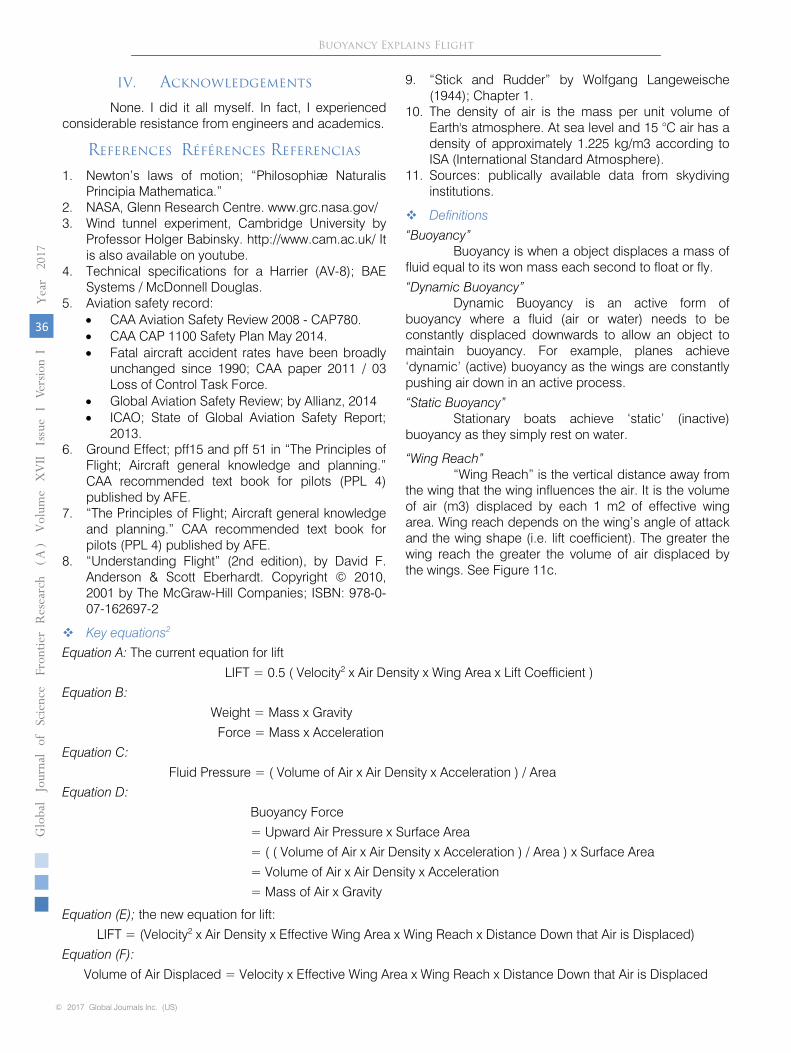
IV. Acknowledgements
None. I did it all myself. In fact, I experienced considerable resistance from engineers and academics.
References Références Referencias
1. Newton’s laws of motion; “Philosophiæ Naturalis Principia Mathematica.”
2. NASA, Glenn Research Centre. www.grc.nasa.gov/ 3. Wind tunnel experiment, Cambridge University by
Professor Holger Babinsky. http://www.cam.ac.uk/ It is also available on youtube.
4. Technical specifications for a Harrier (AV-8); BAE Systems / McDonnell Douglas.
5. Aviation safety record: • CAA Aviation Safety Review 2008 - CAP780. • CAA CAP 1100 Safety Plan May 2014. • Fatal aircraft accident rates have been broadly
unchanged since 1990; CAA paper 2011 / 03 Loss of Control Task Force.
• Global Aviation Safety Review; by Allianz, 2014 • ICAO; State of Global Aviation Safety Report;
2013. 6. Ground Effect; pff15 and pff 51 in “The Principles of
Flight; Aircraft general knowledge and planning.” CAA recommended text book for pilots (PPL 4) published by AFE.
7. “The Principles of Flight; Aircraft general knowledge and planning.” CAA recommended text book for pilots (PPL 4) published by AFE.
8. “Understanding Flight” (2nd edition), by David F. Anderson & Scott Eberhardt. Copyright © 2010, 2001 by The McGraw-Hill Companies; ISBN: 978-0-07-162697-2
9. “Stick and Rudder” by Wolfgang Langeweische (1944); Chapter 1.
10. The density of air is the mass per unit volume of Earth's atmosphere. At sea level and 15 °C air has a density of approximately 1.225 kg/m3 according to ISA (International Standard Atmosphere).
11. Sources: publically available data from skydiving institutions.
Definitions
“Buoyancy” Buoyancy is when a object displaces a mass of
fluid equal to its won mass each second to float or fly.
“Dynamic Buoyancy” Dynamic Buoyancy is an active form of
buoyancy where a fluid (air or water) needs to be constantly displaced downwards to allow an object to maintain buoyancy. For example, planes achieve ‘dynamic’ (active) buoyancy as the wings are constantly pushing air down in an active process.
“Static Buoyancy” Stationary boats achieve ‘static’ (inactive)
buoyancy as they simply rest on water.
“Wing Reach” “Wing Reach” is the vertical distance away from
the wing that the wing influences the air. It is the volume of air (m3) displaced by each 1 m2 of effective wing area. Wing reach depends on the wing’s angle of attack and the wing shape (i.e. lift coefficient). The greater the wing reach the greater the volume of air displaced by the wings. See Figure 11c.
Key equations2
Equation A: The current equation for lift
LIFT = 0.5 ( Velocity2 x Air Density x Wing Area x Lift Coefficient )
Equation B:
Weight = Mass x Gravity
Force = Mass x Acceleration
Equation C:
Fluid Pressure = ( Volume of Air x Air Density x Acceleration ) / Area Equation D:
Buoyancy Force
= Upward Air Pressure x Surface Area
= ( ( Volume of Air x Air Density x Acceleration ) / Area ) x Surface Area
= Volume of Air x Air Density x Acceleration
= Mass of Air x Gravity
Equation (E); the new equation for lift:
LIFT = (Velocity2 x Air Density x Effective Wing Area x Wing Reach x Distance Down that Air is Displaced)
Equation (F):
Volume of Air Displaced = Velocity x Effective Wing Area x Wing Reach x Distance Down that Air is Displaced
© 2017 Global Journals Inc. (US)
1
Globa
lJo
urna
lof
Scienc
eFr
ontie
rResea
rch
V
olum
eXVII
Issue
e
rsion
IV
IYea
r20
17
36
( A)
Buoyancy Explains Flight
Equation (G):
LIFT = Volume of Air Displaced x Air Density x Velocity
Equation (H):
LIFT = Air Mass Displaced x Velocity
V. Summary of Each Section of This Paper
a) Executive summary – abstract This paper demonstrates that buoyancy
explains how planes fly. Archimedes 2,300 year-old principle of
buoyancy explains the physics of how planes fly. To remain airborne planes must displace a mass of air downwards that is equal to their own mass each second. The equal & opposite force pushes the plane up. Otherwise the plane will fall downwards immediately due to gravity. A critical discovery is that buoyancy is measured over a one second time period.
b) Background
The author, methodology, references, and definitions are given.
c) Summary of the paper
This section.
d)
Physics, logic and philosophy
Buoyancy in planes is consistent with the laws of physics, Newton’s laws of motion, the
conservation of
mass and energy, as well as Archimedes principle of buoyancy.
The philosophy is that: Gravity applies universally to all stationary and moving objects.
Buoyancy is a product of gravity. Therefore, buoyancy should apply universally to all
stationary and moving
objects (e.g. planes).
Skydiving is used to demonstrate that Archimedes principle of buoyancy applies to moving
objects and is measured over a one second time period.
e)
The current theories of flight have severe limitations
The current theories of flight have severe limitations and remain unproven. There is no
scientific
experiment on a real aircraft in realistic conditions that proves any theory of flight to
be correct.
Pilots, aviation authorities, academics and engineers still debate the different theories of flight. There is no “official” or generally accepted theory for how planes fly nor any theory that is universally accepted as true.
Current theories of flight ignore buoyancy, which is a fundamental principle of physics that should therefore be applied to planes.
f) Boats, hydrofoils, seaplanes and birds Buoyancy is consistent with the principles of
how boats float, hydrofoils function, seaplanes fly and how birds fly.
g) Buoyancy explains terminal velocity in skydiving.
Calculations of a man skydiving demonstrate buoyancy and proves that it is measured over about a one second time period. i.e. A skydiver in stable free-fall descent, will displace a mass of air equal to his own mass each second (assuming no air friction). Therefore, the same principle applies to planes and all airborne objects.
h) How wings displace air downwards
Propellers (or jets) push the plane forward and thus push the wings through static air. The wings convert this horizontal relative airflow into vertical lift - by pushing the air down. The underside of the wing pushes air down; and the topside of the wing pulls air down. Evidence of planes pushing air down to maintain buoyancy can be seen in the backwash behind planes.
i) Buoyancy explains how planes fly The critical factors that affect lift (aircraft
velocity, air density, wing angle of attack, wing area,…) also affect the amount of air displaced and thus buoyancy. Lift of a wing is proportional to the amount of air that it displaces downwards 8.
The physics and logic are also used to demonstrate that in stable flight, the mass of the plane must equal the mass of the air displaced by the wings each second.
Weight = Buoyancy Force (Lift)
Mass of Plane x Gravity = Mass of Air Displaced x Gravity
Mass of Plane = Mass of Air Displaced
j)
Estimate of air displaced by a wing
Using the example of a Harrier, it is demonstrated that it is theoretically feasible for a
Harrier’s wings to displace a mass of air down equal to its own mass, every second.
Calculations show that a
Harrier only has to displace air down a few meters to
achieve buoyancy. Experimentation needs to be done to
prove this in practice.
k)
Three new concepts to calculate lift.
This paper introduces three changes to the current
equation for lift:
1
Globa
lJo
urna
lof
Scienc
eFr
ontie
rResea
rch
V
olum
eXVII
Issue
e
rsion
IV
IYea
r20
17
37
( A)
© 2017 Global Journals Inc. (US)
Buoyancy Explains Flight

(i) “Wing Reach” (m), Instead of the lift coefficient (e.g. wing angle of attack).
(ii) Effective wing area (m2); Instead of the actual wing area.
(iii) Distance down (m) that air is displaced by the wing is added.
A critical change to the current equation for lift (Equation A), is that if “the distance down that air is displaced by the wing” is added to the existing equation for lift. This provides a more accurate estimate of the mass of air displaced by the wing (and thus buoyancy).
l) Lift equations The current equation for lift, Equation (A) is:
LIFT = 0.5 (Aircraft Velocity2 x Air Density x Wing Area x Lift Coefficient)
If the new concepts above for lift are incorporated into the formula; the current equation for lift (A) can re-stated to:
LIFT = (Aircraft Velocity2 x Air Density x Effective Wing Area x Wing Reach x Distance Down that Air is Displaced each second)
In turn, this can be re-stated to:
LIFT = Volume of Air Displaced x Air Density x Velocity
Which can then be re-stated to the new equation for lift:
LIFT = Velocity x Air Mass Displaced
Or F = mv ; where velocity is velocity of the air directly displaced by the wing.
These equations demonstrate that lift is based on the air mass directly displaced by the wing and consistent with Newtons 2nd law of motion (F = mv). Where lift is the product of the mass of air directly displaced by the wing, times its velocity.
m) Buoyancy is consistent with all empirical observations
Buoyancy in planes is consistent with: The critical factors that affect lift (e.g. aircraft velocity, air
density, wing angle of attack, wing area, …), all flight manoeuvers; (e.g. climb, descent and banking); inverted flight, stalls, ground effect, gliders using air currents to gain altitude, the differences in wing designs, wing vortices, 2D wind tunnel experiments, standard airflow diagrams and winglets.
Wing diagrams in this paper In this paper, the wing diagrams are shown as a
cross section of the wing; see Figure 1a.
Figure 1a: Wing cross-sections
VI. Physics, Philosophy and Logic
a) Buoyancy is consistent with the laws of physics Applying buoyancy to planes is consistent with:
the laws of physics (Newton’s laws of motion) and Archimedes principle of buoyancy; as well as the conservation of momentum, mass & energy.
The energy from the engine is used to push the air mass down and the plane up, with the wings directing the air mass downwards. There is no net loss or gain of mass or energy. In summary, energy is transferred from the plane to the air to achieve lift. The engine generates energy, which is used to create forward movement and push the plane down a runway. The
wings then transfer some of this energy from the
forward motion to push the air down, and
thus to generate lift.
Archimedes principle of buoyancy is measured over about a one second time period. If any
object (e.g.
boat or plane) loses buoyancy for one second, it will sink immediately due to
gravity.
Buoyancy is binary, either an object has
buoyancy or it doesn’t, there is no in-between state (that lasts longer than one second).
b) Philosophy & logic Buoyancy in planes is based on a rational
observation of reality; supported by evidence, logic and reason. It is consistent with what is observed in reality.
© 2017 Global Journals Inc. (US)
1
Globa
lJo
urna
lof
Scienc
eFr
ontie
rResea
rch
V
olum
eXVII
Issue
e
rsion
IV
IYea
r20
17
38
( A)
Buoyancy Explains Flight

This paper simply re-interprets how the principles of physics are applied.
This paper also takes note of Occam’s razor: The simplest explanation given the evidence is often true. Current explanations of flight tend to be highly technical, abstract and complex; and way beyond the understanding of the typical pilot or layman; as well as many engineers and academics.
Propellers and wings have the same basic design and functions; except are aligned in different axis. Propellers push air horizontally backwards to create forward motion. Wings push air vertically downwards to generate lift.
Explanation of why planes can be said to achieve buoyancy: • Fact: Planes push lots of air downwards, so will
displace a mass of air equal to their own mass over some time period (estimated to be each second).
• Conclusion: It is accurate to say that planes achieve buoyancy.
• The laws of physics should be applied universally, not selectively.
• Gravity applies universally to all stationary and moving objects.
• Buoyancy is a product of gravity. • Therefore, buoyancy should apply universally to all
stationary and moving objects (e.g. planes). Gravity and buoyancy applies all the time to all objects; it is universal. Buoyancy doesn’t stop acting on the seaplane just because it’s moving.
Currently Archimedes principle of buoyancy is selectively applied only to static objects, and is not applied to moving objects (such as planes). It has never been proved, or disproved, whether Archimedes’ principle of buoyancy applies to objects that move.
Notes: • In physics, air & water are both fluids; so both boats
and planes are subject to the same principles of physics. Wings are not magic and not exempt from the laws of physics such as buoyancy.
• Boats and hot air balloons float due to buoyancy. There is no reason that planes should be exempt from the need to maintain buoyancy.
• Many people and theories of flight claim that wings are special and therefore subject to special laws of physics that allow planes to fly. If that is the case, then exactly what is the definition of a wing? Exactly at what point do these special laws of physics apply? Note that no current theory of flight defines a wing nor why special conditions should apply to wings.
• This explanation of buoyancy can be applied to anything that floats or flies, such as birds, balloons, skydivers, …
• The Romans understood the concept of heat creating lift, yet never applied it to flight (balloons). I
wonder what seemingly obvious connections we are missing today?
VII. The Current Theories of Flight have
Severe Limitations
There is no “official” or generally accepted theory for how planes fly nor any theory that is
universally accepted as true. A variety of theories are debated among academics, aeronautical engineers, pilots and aviation authorities. The UK Civil Aviation Authority (CAA) claimed in a letter to the author that they endorse no particular theory of flight. Which is odd.
References on the different theories of flight being disputed include:
a.
Bloor, David (2011). “The enigma of the airfoil: Rival theories in aerodynamics.”
b.
New York Times, (9 Dec 2003), “Staying aloft; What Does Keep Them Up There?”
c.
The national (UAE) newspaper (1 Jan 2012): “The secret to airplane flight? No
one really knows”
d.
The (UK) Telegraph newspaper (10 May 2001): “Why theory of flight fails to get off
the ground”.
e.
NASA dispute what pilots are taught as physically impossible. See: NASA (Glenn
Research Centre)
"Incorrect theories of flight” 2: f.
Many universities teach different theories of flight to aerospace engineers.
A problem is that most current theories of flight only describe planes in stable cruise flight or
stalls; and
fail to explain flight manoeuvers (such as a climb, descent, banking and inverted
flight).
Current theories of flight ignore buoyancy; so are therefore incomplete. Not necessarily
wrong, just
incomplete. But probably wrong.
This document does not focus on explaining the current theories of flight in any detail.
For reference, the main current theories of flight in outline include:
1.
Aviation authorities 6 7
typically promote the Venturi
effect, Bernoulli’s principles of fluid dynamics; but
also rely on the Coanda effect and the Magnus effect. In short, the
essential concept is that low air
pressure on the upper airfoil (on the top of the wing),
pulls the plane up.
2.
Pilots tend to believe in theories where high air pressure under the wing pushes the
plane up; such as wing pressure differential and Newtonian theory of lift.
3.
Academics and engineers tend to promote mathematical equations such as Navier-Stokes, RANS, …... Also: Kutta effect, Laminar air flow, and various alternative
theories derived from these concepts.
4.
The current equation for lift 2, which is known to be only approximate (Equation A):
1
Globa
lJo
urna
lof
Scienc
eFr
ontie
rResea
rch
V
olum
eXVII
Issue
e
rsion
IV
IYea
r20
17
39
( A)
© 2017 Global Journals Inc. (US)
Buoyancy Explains Flight
LIFT = 0.5 (Aircraft Velocity2 x Air Density x Wing Area x Lift Coefficient)
An explanation of the current theories of flight can be found in articles such as:
a. “12 Theories of flight “– on youtube channel N Landell (the author of this paper).
b. “How Planes Fly” - Michigan Engineering lecture by Krzysztof Fidkowski on youtube.
c. Doug McLean “Common Misconceptions in Aerodynamics;“ on youtube.
d. Article by aerodynamics professors on the theory of flight: www.aviation-history.com/theory/lift.htm
e. Cambridge University lecture on aerodynamics: “Wing lift Holger Babinsky” see youtube: or “How wings really work” http://www.cam.ac.uk/
f. Anderson/Eberhardt “Understanding Flight” (2010) and "How Airplanes Fly: A Physical Description of Lift."
g. “Stick and Rudder” (1944) by Wolfgang Langeweische.
VIII. Boats, Hydrofoils, Seaplanes and Birds
The principle of buoyancy is consistent with how boats, hydrofoils, seaplanes and birds float or fly.
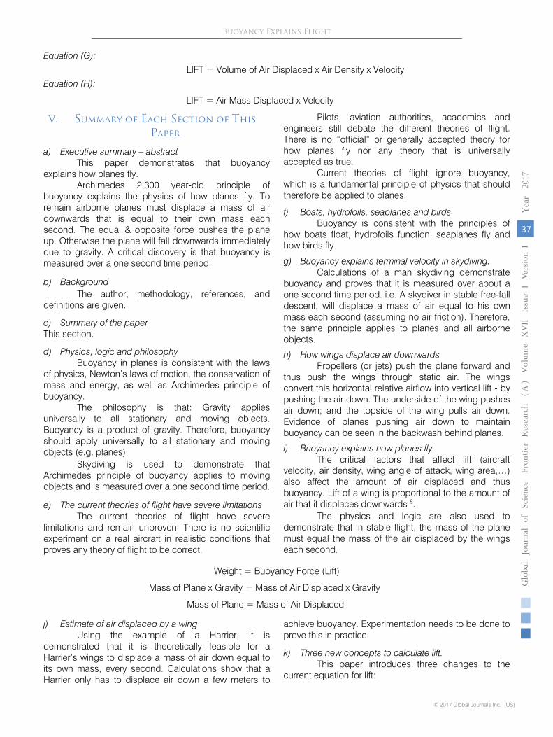
a) Boats and Archimedes principle of buoyancy According to physics established by
Archimedes 2 , to float, the mass of the boat will equal the mass of the water displaced by the boat. Boats float due to an upward buoyancy force equaling the downward weight of the boat, as shown by Figure 6a. The buoyancy force is just the upward water pressure at the bottom of the boat; which is equal to the amount of water pushed up by the boat. Pressure and weight are both arise due to gravity.
Figure 6a: Buoyancy in boats
Archimedes principle of buoyancy is described by the equations: 2
Weight = Buoyancy Force (Water Pressure)
Mass of Boat x Gravity = Mass of Water Displaced x Gravity
Mass of Boat = Mass of Water Displaced
To say that the boat floats because the water pressure under the hull equals the weight of
the boat is correct, but incomplete. The mass of the water displaced must also equal the
mass of the boat. The same applies to planes. It is not the whole story just to say that the lift
on the plane will equal its weight. The mass of the plane must also equal the mass of the air
displaced each second.
b)
Speed boats
Applying Archimedes principle of buoyancy to moving boats explains why they rise up in the
water when the go faster. When a boat starts moving, buoyancy doesn’t stop being relevant.
As the boat moves faster it displaces a greater amount of water and air. This increases the
pressure at the bottom of the boat. As the weight of the boat remains unchanged, the
increased buoyancy force pushes the boat up. Speed
boats can achieve lift and rise out of
the water without wings. See Figure 6b.
© 2017 Global Journals Inc. (US)
1
Globa
lJo
urna
lof
Scienc
eFr
ontie
rResea
rch
V
olum
eXVII
Issue
e
rsion
IV
IYea
r20
17
40
( A)
Buoyancy Explains Flight

Figure 6b: Speed boat achieving lift
c)
Hydrofoils
In addition, some boats have hydrofoils (that are like airfoils) which provide lift and raise the
boat
higher out of the water. See Figure 6c. Hydrofoils
function on the same principle as airfoils (wings). Except
that as water is denser, it is easier to achieve greater lift for a given
velocity.
Figure 6c: Hydrofoils
d) Seaplanes Add wings to a boat and at high speed the boat
becomes a seaplane that floats on the air. Planes are just boats with wings. Boats float due to buoyancy in
water; and planes fly due to buoyancy in the air. This is demonstrated by the simple progression from a stationary seaplane floating in water, to moving forwards and flying in the air. See Figure 6d.
Figure 6d: Seaplane
e)
Birds fly by pushing air downwards
This is easily established by watching a slow motion video of a bird flying; see Figure 6e.
This is
consistent with the concept that birds fly by maintaining their buoyancy in the air.
The wing “up-stroke” raises the wings without displacing much air.
1
Globa
lJo
urna
lof
Scienc
eFr
ontie
rResea
rch
V
olum
eXVII
Issue
e
rsion
IV
IYea
r20
17
41
( A)
© 2017 Global Journals Inc. (US)
Buoyancy Explains Flight

The wing down-stroke” pushes air downwards.
(Source: youtube video)
Figure 6e: Sequence of bird flapping its wings
f) Example of a stone falling in different fluids A stone falling at terminal through water and air
demonstrates the principle of buoyancy applied to moving objects.
This paper claims that at terminal velocity a stone displaces a mass of air or water downwards equal to its own mass each second, consistent with the principle of buoyancy. See Figure 6f (stone falling in fluids.)
The speed of the stone depends primarily on how far it must fall each second before it displaces a mass equal to its own mass. Water has a much greater density (mass per unit volume) than air. Consequently, the stone falls a much smaller distance in water than air each second. The mass of water or air displaced, includes both the mass directly in the path of the stone, as well as the mass that is indirectly displaced.
Figure 6f: Stone falling in fluids
Note that water is more viscous than air, so the friction
will be greater than in the air. But this
remains a
relatively minor consideration in this example.
Results: The difference speeds of stone falling in water
and air at terminal velocity is
consistent with the principle of buoyancy. Experimentation needs to be done to verify exactly
what the difference is.
IX. Buoyancy
Explains
Terminal
Velocity
in Skydiving
This section demonstrate via calculations that it is theoretically feasible for a man to displace
a mass of
air equal to his own mass each second, at terminal velocity while in a free-fall
descent. See Figure 7a.
Experimentation needs to be done to confirm this is actually what
happens.
© 2017 Global Journals Inc. (US)
1
Globa
lJo
urna
lof
Scienc
eFr
ontie
rResea
rch
V
olum
eXVII
Issue
e
rsion
IV
IYea
r20
17
42
( A)
Buoyancy Explains Flight

Figure 7a: Skydiver at terminal velocity
In physics, all movement is relative. So to demonstrate buoyancy, it does not matter if the skydiver is falling through stationary air, or if the stationary skydiver is having air blown upwards. The physics is the same, assuming that air is Galilean invariant.
Assumptions • 80 kg man in stable free-fall; descends at a velocity
of 66.7 m/s (or 210 km/hr) 11. This estimate is based on anecdotal evidence from skydivers and skydiving organizations. The 80 kg includes his clothes and equipment.
• Lower surface area of the skydiver is based on half the estimated the total body surface area (BSA) for a man 180 cm tall; using the Du Bois and Motseller formula. Note that the skydiver’s lower legs are partially obscured from the direction of descent, but this is compensated for by the skydiver’s clothes and equipment.
• Standard air density 2 3 = 1.2 kg/m3.
• Calculations exclude any significant friction that would slow the skydiver’s descent. The viscosity of air is low, so air friction is considered to be negligible.
• The skydiver only displaces air that is directly in his path.
• No air is indirectly displaced by the skydiver. This parameter is extremely difficult to estimate. This assumption means that the estimate of the total air displaced by the skydiver is under-estimated.
• Each 1 kg/s of air displaced must be displaced down by the skydiver about 0.83 meters; given that the density of the air is 1.2 kg/m3 (0.83 m = 1 kg / 1.2 kg/m3).
These estimates and assumptions are approximate, as they are only used to demonstrate the feasibility and reasonableness of the argument for buoyancy.
Calculations First, the volume of air displaced by the skydiver is estimated:
= Velocity of Skydiver x Lower Surface Area of Skydiver
Then: Mass of Air Directly Displaced = Volume of Air Displaced x Air Density Based on the principle of buoyancy, the terminal velocity of the skydiver is estimated based on his mass:
Table 1
Results Terminal velocity for skydiver’s with a mass on
60-90 kg is 208-255 km/hr. This is consistent with what is observed in reality; based on evidence from skydiving institutions and skydivers. For example, a 80 kg skydiver could directly displace 80 kg of air each second; at a terminal velocity of 66.7 m/s. Conclusion
Based on the assumptions above, it is feasible a skydiver at terminal velocity to displace a
mass of air
equal to his mass each second. This is consistent with what is observed in
reality.
Reasonableness check – Indoor skydiving
1
Globa
lJo
urna
lof
Scienc
eFr
ontie
rResea
rch
V
olum
eXVII
Issue
e
rsion
IV
IYea
r20
17
43
( A)
© 2017 Global Journals Inc. (US)
Mass of Skydiver kg 60.0 70.0 80.0 90.0Surface Area m2 0.87 0.94 1.00 1.06
Terminal Velocity m/s 57.8 62.4 66.7 70.8Terminal Velocity km/hr 208 225 240 255Mass of Air kg 60.0 70.0 80.0 90.0Directly Displaced.
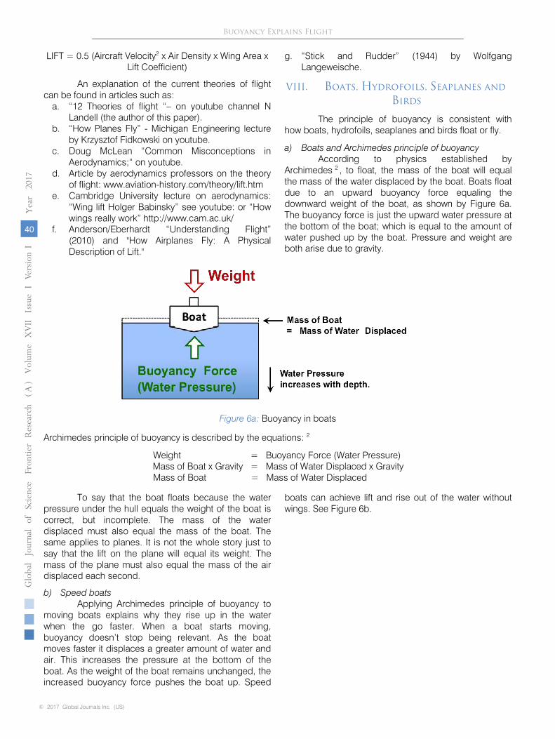
Indoor skydiving centers provide a reasonableness check that the terminal velocity for a 80kg man skydiving is 66.7 m/s.
Buoyancy Explains Flight
A large fan is used to blow air upwards, to suspend a man in the air. See Figure 7b (Skydiving practice). Anecdotal evidence shows that the skydiver remains suspended mid-air if the fan blows the air up at
the same speed as the man’s terminal velocity when actually
skydiving. So a fan blowing with a 80 kg/s force (with air blown up at 66.7 m/s), can suspend
a 80 kg man mid-air. This speed of 66.7 m/s is well within the range that indoor skydiving
centers advertise for the capacities of their fans.
Results:
The range of velocity of air blown upwards at indoor skydiving centers is consistent
with the terminal velocity calculations of free-fall skydiving above, of 66.7 m/s for a 80 kg
man. The man is floating in the air based on the same principles of physics that explain how
boats float on water.
Figure 7b:
Skydiving practice
X.
How
Wings
Displace
Air
Downwards
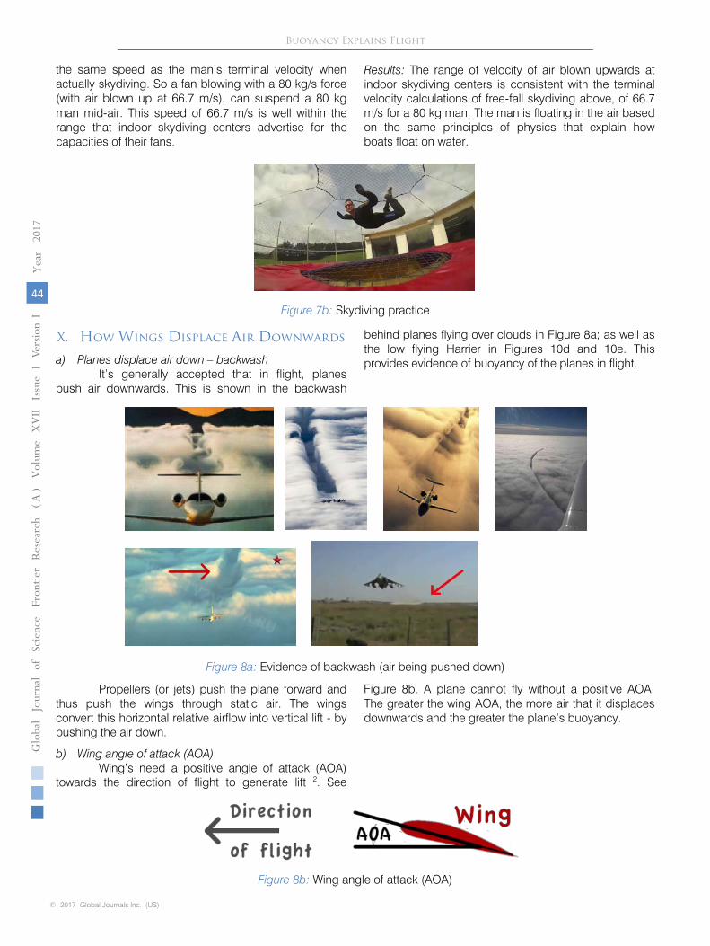
a) Planes displace air down – backwash
It’s generally accepted that in flight, planes push air downwards. This is shown in the
backwash
behind planes flying over clouds in Figure 8a; as well as the low flying Harrier in
Figures 10d and 10e. This provides evidence of buoyancy of the planes in flight.
Figure 8a:
Evidence of backwash (air being pushed down)
Propellers (or jets) push the plane forward and thus push the wings through static air. The
wings convert this horizontal relative airflow into vertical lift - by pushing the air down.
b) Wing angle of attack (AOA)
Wing’s need a positive angle of attack (AOA) towards the direction of flight to generate lift 2. See
Figure 8b. A plane cannot fly without a positive AOA. The greater the wing AOA, the
more air that it displaces downwards and the greater the plane’s buoyancy.
© 2017 Global Journals Inc. (US)
1
Globa
lJo
urna
lof
Scienc
eFr
ontie
rResea
rch
V
olum
eXVII
Issue
e
rsion
IV
IYea
r20
17
44
( A)
Buoyancy Explains Flight
Figure 8b: Wing angle of attack (AOA)

c) How a wing pushes air down
Wings essentially have two key functions: To “catch” air, then to displace this air
downwards. See Figure 8c.
Figure 8c:
Wing; Two lift determinants
The wing displaces static air downwards and slightly forwards, as shown in Figure 8d. The
wing splits the air mass into two separate and distinct airflows; above and below the wing.
d) Two wing
airflows and two upward forces
Applying Newtons 3rd
law of
motion to planes; In stable flight every force must have an equal
& opposite force 1. The weight of the plane exerts a downward force on the air, (ACTION).
In stable flight, there is an equal and opposite force (REACTION), pushing the plane up (lift).
In summary, the air is being pushed down and the plane is pushed up. The plane is being
supported by the air immediately under the wing, as well as all the air recently displaced by
the wing (in the previous one second).
1
Globa
lJo
urna
lof
Scienc
eFr
ontie
rResea
rch
V
olum
eXVII
Issue
e
rsion
IV
IYea
r20
17
45
( A)
© 2017 Global Journals Inc. (US)
Buoyancy Explains Flight
Figure 8d: Wing displacing air molecules down

Figure 8e:
Details of plane displacing air down
As shown in Figure 8e; the plane is pushed and pulled upwards by two the separate airflows:
(1)
The underside of the wing faces the direction of flight and COMPRESSES the lower air
mass under the wing. This produces high air pressure and PUSHES the lower air mass
down. The equal and opposite force generated under the airflow pushes the plane up.
(2)
The topside of the wing faces away from the direction of flight. As this air is expands
behind the wing, this produces low air pressure. This PULLS the upper air mass downwards.
The equal and opposite force generated above the airflow pulls the plane up.
Note that buoyancy is no more a “Newtonian Theory of lift” than walking or swimming are
“Newtonian Theories of walking or swimming.” Newtons laws of motion are applied
universally.
keeps
the plane up by pushing air down. It shoves air down with the bottom surface, and it pulls air
down with the top surface. But the really important thing to understand is that the wing, in
whatever fashion, makes air go down. In exerting a downward force on the air, the wing
receives an upward counterforce – by the same principle, known as Newton’s law of action
and reaction, ….” as well as: “That’s what keeps a plane up. Newton’s law says that if the
wing pushes the air down, the air must push the wing up.”
By comparison, birds push against the air to fly, fish push against water to swim, people push
against the ground to walk or jump. In contrast, people cannot walk on water or air as there is
insufficient resistance and “equal & opposite” force to a person’s weight. In turn, this is due
to a lack of substance to push against (and thus insufficient pressure under your feet). But
when a person is submerged in water, they can achieve buoyancy (i.e. swim).
e) Net wing air pressure
There is a net air pressure on the wing; with high pressure under the wing and low pressure
above the wing. See Figure 8f.
© 2017 Global Journals Inc. (US)
1
Globa
lJo
urna
lof
Scienc
eFr
ontie
rResea
rch
V
olum
eXVII
Issue
e
rsion
IV
IYea
r20
17
46
( A)
Buoyancy Explains Flight
Figure 8f: Wing Air Pressure Diagrams
Key referenceThe book: “Stick and Rudder” by Wolfgang
Langeweische (1944). 9 which is famous among pilots for its accurate, practical and common-sense advice on how to fly a plane well. In Chapter 1 the book states: “The main fact of heavier-than–air-flight is this: the wing
g) How far down each kilogram of air is displaced
As 1 m3
of air has a mass of 1.2
kg (at a standard air density of 1.2 kg/m3); Then in order for
it to displace 1 kg of air, this 1 m3
of air must be displaced down about 0.83 meters, (as: 0.83
m = 1 kg /
1.2 kg/m3).
The farther that each 1 kg of air is displaced (pushed or pulled) by the wings, then the more
air that is displaced; and the greater air mass displaced in total. Consequently, if each 1 m3
of air is displaced down over 1.66 meters by the wings. Then a total of 2 kg of air mass is
displaced (as: 0.83 m x 2 = 1.66 m).
However, for the purpose of simplicity and conservatism; this paper assumes that the wings
must push each 1 m3 of air down 1 meter to displace 1 kg of air. (which is slightly more than
the 0.83 meters required).
h) A key reference – The book ‘Understanding Flight’ 8
The extracts below from this book, are directly compatible with the physics of the buoyancy
explanation of how planes fly. The critical difference is that the book does not use the
terminology “buoyancy” and focus analysis on the velocity of air displaced by the wing, rather
than the mass of air displaced. The book attributes lift to air being displaced downwards that
then causes low air pressure on the top of the wing; which
pulls the plane up.
Extracts from the book Understanding Flight 8; Chapter 1,
Principles of
flight.
•
“The air behind the wing is going almost straight down ….. the air has, in fact, a slight
forward direction.”
•
“In the simplest form, lift is generated by the wing diverting air down, creating the
downwash.”
•
“From Newton’s second law, one can state the relationship between the lift on a wing
and its downwash: The lift of a wing is proportional to the amount of air diverted per
time times the vertical velocity of that air.”
•
“….. the lift of a wing is proportional to the amount of air diverted (down) per time
times the vertical velocity of that air.”
•
“… where the air is initially at rest and the wing is moving, the air is moving almost
straight down after the wing passes.”
•
“The key thing to remember about lift is that it is a reaction force caused by the
diversion of air down.”
•
“The physics of diverting the air down are expressed by the lowering of the pressure
on the top of the wing producing the lifting force. The lift of a wing is proportional to
the amount of air diverted times the vertical velocity of that air.”
XI.
Buoyancy
Explains
How
Planes
Fly
a) The critical factors that affect lift
Buoyancy is consistent with the critical factors that affect lift, as shown in Figure 9a. The
factors that affect lift also affect the amount of air displaced and thus buoyancy.
Buoyancy increases with:
•
Aircraft velocity.
•
Air density (lower altitudes).
•
Wing area.
•
Wing angle of attack.
•
The distance down that air is displaced.
1
Globa
lJo
urna
lof
Scienc
eFr
ontie
rResea
rch
V
olum
eXVII
Issue
e
rsion
IV
IYea
r20
17
47
( A)
© 2017 Global Journals Inc. (US)
Buoyancy Explains Flight
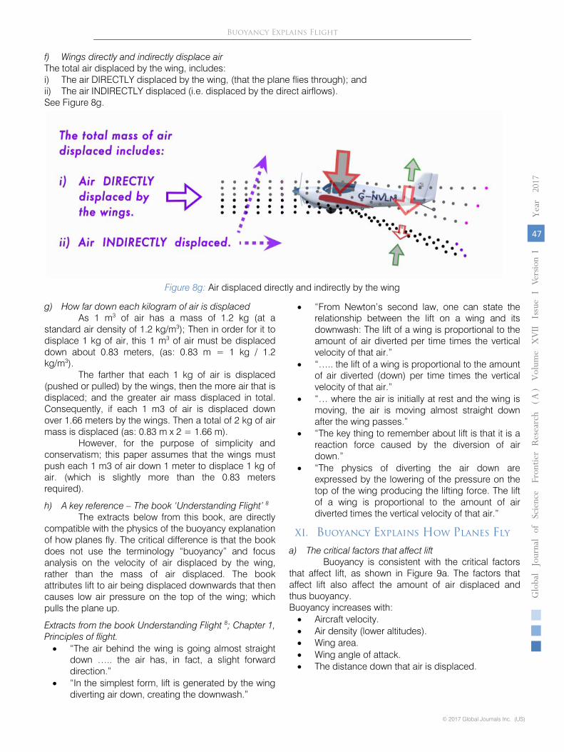
Figure 8g: Air displaced directly and indirectly by the wing
f) Wings directly and indirectly displace airThe total air displaced by the wing, includes:i) The air DIRECTLY displaced by the wing, (that the plane flies through); andii) The air INDIRECTLY displaced (i.e. displaced by the direct airflows).See Figure 8g.

Figure 9a: The critical Factors that affect lift
b) Mass of Plane = Mass of Air Displaced
To fly, according to buoyancy, a plane must displace a mass of air downwards equal to their own
mass,
each second. If they don’t, then they sink due to gravity. Air goes down and the plane goes up. See Figure 9b. In
summary:
ACTION = REACTION
Weight (downward force) = Buoyancy Force (Lift)
Mass of Plane x Gravity = Mass of Air Displaced x Gravity
Mass of Plane = Mass of Air Displaced
ACTION = REACTION
There must be resistance to the ACTION force to generate a REACTION. The downward
force (ACTION) due to the weight of the plane, will push the plane downwards unless there is
something to resist and push back (i.e. upwards); to create the “equal & opposite” Buoyancy
Force (REACTION). That resistance can only be the net air pressure on the wing due to the
air displaced down. There is nothing else that can provide resistance to the downward force.
To put it another way. The plane will only takeoff from the runway once the plane is pushing
enough air downwards to support its weight. Therefore, logically the mass of the plane must
equal the mass of the air displaced (each second); similar to a boat floating in water.
Downward Force (weight) = Buoyancy Force (lift)
To put it another way. The force required to generate lift, needs to be a sufficient force to: (i)
Counter-act gravity and the mass of the plane (weight). And (ii) Displace enough air mass
to generate enough lift.
(i)
Counter-act gravity and the mass of the plane
Using Newton’s second law of motion 1
(F = ma);
Downward Force (kg m/s2)
(i.e. the plane’s weight)
= Mass (kg) x Acceleration (m/s2)
= Mass of Plane x Gravity
(ii)
Displace enough air mass (i.e. buoyancy) to generate enough lift
© 2017 Global Journals Inc. (US)
1
Globa
lJo
urna
lof
Scienc
eFr
ontie
rResea
rch
V
olum
eXVII
Issue
e
rsion
IV
IYea
r20
17
48
( A)
Buoyancy Explains Flight
The Buoyancy Force generated is proportional to the air displaced down by the wing 8. Also, the
Figure 9b: Newton & Buoyancy

wing (see Figure 8f – net wing air pressure). This is
calculated in a similar way as buoyancy for a boat:
The standard formula for static fluid pressure 2:
Pressure = (Density x Volume x Acceleration) / Area.
This can be adjusted to a total upward Buoyancy Force as follows 2:
Buoyancy Force
= Pressure x Area
= ((Density x Volume x Acceleration)/Area) x Area
= Density x Volume x Acceleration
As Mass = Density x Volume; Then:
Buoyancy Force (kg m/s2)
= Mass of Air Displaced (kg) x Gravity (m/s2)
Conclusion
In stable flight these two forces above will be equal:
XII.
Estimate of Air
Displaced by a
Wing
a) Mathematical proof of concept - Harrier Example
An example calculation to demonstrate that it’s theoretically feasible for a plane’s wings to
displace
enough air each second to keep the plane airborne, per buoyancy. See Figure 10a.
Figure 10a:
Proof of Concept – Harrier Figure
10b:
Harrier Lift Factors
This provides the mathematical proof that it is feasible that a Harrier (AV-8) could displace a
mass of air equal to its own mass, every second. See Figure 10b.
Example:
To stay airborne, a 10,000 kg Harrier 4
flying at 800 km/hr (222 m/s); needs to
displace 45 kg (or 37.5 m3) of air down - every meter flown (each second).
Mass of air displaced every meter, each second flown
= Mass of Harrier / Speed of Harrier
= 10,000 kg / 222 m/s
= 45 kg / (m/s)
Using standard air density 2 10, (of 1.2 kg/m3), to
convert the mass of air into a volume of air:
Volume of Air
= Mass of Air / Air Density
= 45 kg / 1.2 kg/m3
= 37.5 m3
Results:
the Harrier’s wings need to displace 37.5 m3
of
air, each meter flown, each second.
It is feasible for the Harrier to displace the
required 37.5 m3
of air, each meter flown,
each second. This can be described in two ways:
Method 1:
The Harrier 5
has a 22.6 m2
wing area with a 9.4 m leading edge (facing the direction of
flight). It is feasible to displace 37.5 m3
of air; If the wings displace 1.0 m3
of air each meter
flown, along each meter of it’s
9.4 m leading edge; down at least 4.0 m. See Figure 9a and
10c.
Note the terminology:
“Distance Down” = “Distance that Air is Displaced Down each second (m/s)”
“Volume of Air” = “Volume of Air Displaced each second (m3/s) ”
“Leading Edge” = “Length of the Leading Edge of the Wing (m)”
Volume of air displaced down (every meter each second.)
= Leading Edge x Volume of Air x Distance Down
= ( 9.4 m x 1.0 m3
)
x 4.0 m
= 37.5 m3
So, each meter
of the leading edge of the wing, is displacing 1 m3
of air, down 4 m; each
meter flown, as shown by Figure 10c. This means that each meter that the Harrier flies; It
only needs to displace all the air 0.5 m above & below the wing, down 4 m.
1
Globa
lJo
urna
lof
Scienc
eFr
ontie
rResea
rch
V
olum
eXVII
Issue
e
rsion
IV
IYea
r20
17
49
( A)
© 2017 Global Journals Inc. (US)
Buoyancy Explains Flight
Buoyancy Force is due to the net air pressure on the

Figure 10c:
Air Displaced by Harrier Wing
Method 2:
The Harrier’s wings can displace 37.5 m3
of air, each meter flown, each second; If the 22.6 m2
wings (with an effective wing area 9.4 m2) has a 1.0 m wing reach, and displaces this air
down 4.0 m. See Figure 9a and 10c.
Volume of air displaced down (every meter each second.)
= Effective Wing Area x Wing Reach x Distance Down
= ( 9.4 m2
x 1.0 m ) x 4.0 m
= 37.5 m3
Results:
These calculations demonstrate that it’s feasible for the Harrier’s wings to displace enough
air to keep the plane airborne. Note that the Harrier does not have to displace the air down
very far to allow it to achieve buoyancy, just a few meters.
Evidence that a Harrier can displace significant amounts of air downwards, is provided from
videos of a low-flying Harrier in Figures 10d and 10e:
Figure 10d: Harrier approaching an observer:
Figure 10e: Harrier departing from the same observer
(Source: youtube video)
A key issue is the distance away from the wing that the wing affects the air. The wings affect the air unequally across the wingspan and the air closest to the wings are affected the most.
Results This demonstrates that it’s feasible for the
Harrier’s wings to displace enough air each second to keep the plane airborne.
© 2017 Global Journals Inc. (US)
1
Globa
lJo
urna
lof
Scienc
eFr
ontie
rResea
rch
V
olum
eXVII
Issue
e
rsion
IV
IYea
r20
17
50
( A)
Buoyancy Explains Flight

Extracts from the book: ‘Understanding Flight‘ 8; Chapter 1, Principles of flight.
Estimate of air displaced by a plane. The authors of the book Understanding Flight
do a back-of-the-envelope calculation to estimate that: “Thus a Cessna 172 at cruise is diverting about five times its own weight in air per second to produce lift.”
The quote in detail: “Take, for example, a Cessna 172 that weighs about 2300 lb. (1045 kg). Traveling at a speed of 140 mi/h (220 km/h) and assuming an effective angle of attack of 5 degrees, we get a vertical velocity for the air of about 11.5 mi/h (18 km/h) right at the wing. If we assume that the average vertical velocity of the air diverted is half this value, we
calculate from Newton’s second law that the amount of air diverted is on the order of 5 (English) tons per second. Thus a Cessna 172 at cruise is diverting about five times its own weight in air per second to produce lift. “
XIII. Three New Concepts to Calculate Lift
a) Current equation for lift Current aviation textbooks 2 6 7 state that the
accepted equation for lift is (Equation A): LIFT = 0.5 (Aircraft Velocity2 x Air Density x Wing Area x Lift Coefficient) See Figure 11a for an illustration of these factors.
Figure 11a: Wing; Factors affecting lift
Notes:
• The lift co-efficient includes the wing shape and the angle of attack (AOA).
• Velocity is the speed of the aircraft relative to the air.
• The current equation for lift implicitly includes and a partial estimate for the volume of air displaced by the wing, but excludes how far down this air is displaced by the wing.
• A problem is that the lift coefficient cannot be directly measured and changes constantly (to make the equation work).
• The equation is not influenced by the mass of air that the wings displace; not how far down this air s displaced.
• This equation is known to be approximate and imprecise (mainly due to the lift coefficient); which is often resolved by using the lift coefficient as a residual parameter that is adjusted to make the equation work.
• Lift also depends on air compressibility and viscosity. But this is not material to this paper and beyond the scope of what is being discussed.
b) Three new concepts to calculate lift are introduced
To obtain a more accurate estimate of the air mass displaced by the wings (and thus buoyancy), the current equation for lift (Equation A):
LIFT = 0.5 (Aircraft Velocity2 x Air Density x Wing Area x Lift Coefficient)
is adjusted to produce a new equation for lift, Equation (E):
LIFT = (Aircraft Velocity2
x Air Density x Effective Wing Area x Wing Reach
x Distance Down that Air is Displaced each second)
(See Figure 11b.)
The “0.5” factor is also removed from the equation; as this is part of the calculation of the
effective wing area. The explanation of this is complex and beyond the scope of this paper.
But in short; 0.5 x Wing Area = Effective Wing Area. (approximately)
1
Globa
lJo
urna
lof
Scienc
eFr
ontie
rResea
rch
V
olum
eXVII
Issue
e
rsion
IV
IYea
r20
17
51
( A)
© 2017 Global Journals Inc. (US)
Buoyancy Explains Flight
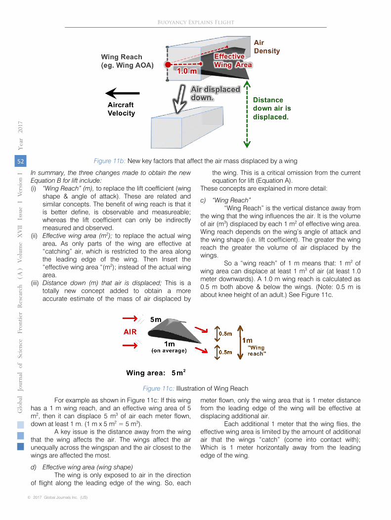
Figure 11b:
New key factors that affect the air mass displaced by a wing
In summary, the three changes made to obtain the new Equation B for lift include:
(i)
“Wing Reach” (m),
to replace the lift coefficient (wing shape & angle of attack).
These are related and similar concepts. The benefit of wing reach is that it is
better define, is observable and measureable; whereas the lift coefficient can only
be indirectly measured and observed.
(ii)
Effective wing area (m2);
to replace the actual wing area. As only parts of the
wing are effective at “catching” air, which is restricted to the area along the
leading edge of the wing. Then Insert the “effective wing area “(m2); instead of
the actual wing area.
(iii)
Distance down (m) that air is displaced;
This is a totally new concept added to
obtain a more accurate estimate of the mass of air displaced by
the wing. This is
a critical omission from the current equation for lift (Equation A).
These concepts are explained in more detail:
c) “Wing Reach”
“Wing Reach” is the vertical distance away from
the wing that the wing influences the air. It
is the volume of air (m3) displaced by each 1 m2
of effective wing area. Wing reach depends
on the wing’s angle of attack and the wing shape (i.e. lift coefficient). The greater the wing
reach the greater the volume of air displaced by the wings.
So a “wing reach” of 1 m means that: 1 m2
of wing area can displace at least 1 m3
of air (at
least 1.0 meter downwards). A 1.0 m wing reach is calculated as 0.5 m both above & below
the wings. (Note: 0.5 m is about knee height of an adult.) See Figure 11c.
Figure 11c:
Illustration of Wing Reach
For example as shown in Figure 11c: If this wing has a 1 m wing reach, and an effective
wing area of 5 m2, then it can displace 5 m3
of air each meter flown, down at least 1 m. (1 m x 5 m2
= 5 m3).
A key issue is the distance away from the wing that the wing affects the air. The wings affect
the air unequally across the wingspan and the air closest to the wings are affected the most.
d) Effective wing area (wing shape)
The wing is only exposed to air in the direction of flight along the leading edge of the wing.
So, each
meter flown, only the wing area that is 1 meter distance from the leading edge of
the wing will be effective at displacing additional air.
Each additional 1 meter that the wing flies, the effective wing area is limited by the amount of
additional air that the wings “catch” (come into contact with); Which is 1 meter horizontally
away from the leading edge
of the wing.
© 2017 Global Journals Inc. (US)
1
Globa
lJo
urna
lof
Scienc
eFr
ontie
rResea
rch
V
olum
eXVII
Issue
e
rsion
IV
IYea
r20
17
52
( A)
Buoyancy Explains Flight

Figure 11d: Example of effective wing area, propeller plane
For example, the wing in the Figure 11d (effective wing area) has a 5.6 m leading edge and is 2.0 m deep on average. Hence it has an effective wing area of 5.6 m2; (i.e. 1 m x 5.6 m = 5.6 m2). This is half
the size of the total wing area of 11.2 m2. This wing design of a relatively modest leading edge will catch a reasonable amount of air; but the deep wings will push the air a relatively far distance down.
Figure 10e: Glider wings Figure 10f: Propeller plane wings
In contrast to this propeller plane wing; gliders have no propeller but wide, thin, and light wings (See Figure 11e and 11f). This wide wing design has the maximum effective wing area to the direction of flight, so will “catch” a significant amount of air each meter flown. But the wings are less able to displace air down very far as they are thin.
Conclusion This difference in wing shape and effective wing
area between gliders and propeller plane examples above is consistent with the logic of buoyancy. Whereas, the current theories of lift provide no explanation for these differences in wing design.
e) Distance down that air is displaced The total mass of air displaced by the wing also
depends on how far down that the wing displaces air hitting the wing. The air directly displaced by the wing, will indirectly displace additional air above and below the wing.
The further each 1 m3 air is displaced down, then the more air mass in total that is displaced by the wing, and the greater the lift and buoyancy generated. Also, the greater the energy transferred from the wings to the air, so the greater the lift.
The distance (m) that each 1 m3 of air is displaced down by the wing depends primarily on: the angle of attack (AOA), the shape of the wing, wing
vortices, and the aircraft’s momentum (the velocity and mass of the aircraft). The greater the aircraft momentum, the easier it will be for the wings to push air further down.
The wings displace air down unequally across the wingspan. Air closest to the fuselage will be pushed down the most, as this is where the wings are deepest (from front to back).
The presence of descending wing vortices (spiraling air), will also impact the amount of air displaced and how it is displaced. But this is beyond the scope of this paper.
This is the most significant change made to current equation for lift (Equation A). This provides a more accurate estimate of the mass of air displaced by the wing (and thus buoyancy).
1
Globa
lJo
urna
lof
Scienc
eFr
ontie
rResea
rch
V
olum
eXVII
Issue
e
rsion
IV
IYea
r20
17
53
( A)
© 2017 Global Journals Inc. (US)
Buoyancy Explains Flight

XIV. A New Equation for Lift
For air that is directly displaced by the wing:
The current Lift Equation (A):
LIFT = 0.5 (Aircraft Velocity2 x Air Density x Wing Area x Lift Coefficient)
As explained above in Section 10, this equation (A) for lift should be adjusted by: (i) Wing Reach to replace lift coefficient. (ii) Effective Wing Area to replace the wing area. (iii) Distance down that air is displaced is added.
To produce the equation (E):
LIFT = (Aircraft Velocity2 x Air Density x Effective Wing Area x Wing Reach
x Distance Down that Air is Displaced each second)
Given that:
Volume of Air Displaced = Velocity x Effective Wing Area x Wing Reach x Distance Down
Then, the equation for lift (E) above can be simplified to the equation (G):
LIFT = Volume of Air Displaced x Air Density x Velocity
Then this equation (G) can be re-stated to equation (H):
LIFT = Air Mass Displaced x Velocity
This last equation (H) is essentially the same formula as Newton's second law of motion (F = mv); So it is consistent with current physics (newton’s second law of motion).
But for this new equation (H) to fit with established physics, then “velocity” must be the velocity of the air displaced; not aircraft velocity; As this equation relates top the energy transferred from the wing to the air.
F = mv is also the formula used to estimate the thrust (lift) generated by a rocket; where: Thrust (Force) = Mass x Velocity of the exhaust gases.
See Figure 12a.
Figure 12a: Rocket propulsion. F = mv
Therefore the new equation for lift based on the mass and velocity of the air displaced, is consistent with current physics of propulsion. The force generated (lift) in both is determined by the formula F = mv.
XV. Buoyancy is Consistent with
Empirical Observations
Buoyancy is consistent with all empirical observations related to flight. This is explained in more detail in the video on youtube; “Buoyancy explains how planes fly – FULL,” (about 1 hour long by N Landell). Specifically:
1. How birds and planes both push air downwards during flight. See Figure 6e.
2. How boats rise up in the water when they go faster. Buoyancy increases as more water is pushed downwards by the moving boat.
3. The critical factors that affect lift; Buoyancy of a plane increases with: a. Aircraft velocity, b. Air density, c. Wing area, d. Wing angle of attack, and e. The distance down that air is displaced.
And therefore buoyancy is consistent with the current Equation (B) for lift.
LIFT = 0.5 (Aircraft Velocity2 x Air Density x Wing Area x Lift Coefficient)
© 2017 Global Journals Inc. (US)
1
Globa
lJo
urna
lof
Scienc
eFr
ontie
rResea
rch
V
olum
eXVII
Issue
e
rsion
IV
IYea
r20
17
54
( A)
Buoyancy Explains Flight

4. All flight manoeuvers; such as climb, descent and banking. The airflow around the wings is simply re-directed by the planes controls to obtain the desired flight manoeuvers. This is similar to how boats steer or manoeuvers in water.
5. Inverted flight. In inverted flight a positive angle of attack (AOA) is maintained; and airflows are essentially similar to normal flight. The main difference between inverted and normal flight is that the plane has a much less aerodynamic orientation to the direction of flight, so is less efficient at generating lift. See Figure 13c.
6. Stalls; An aircraft stall is typically abrupt and dramatic, somewhat similar to a boat sinking. Buoyancy is lost with a relatively small decline in aircraft velocity; at which point the plane ceases to generate any lift and falls like a stone.
7. Ground effect; where on landing the wings compress air between them and the runway to create an “air cushion” that boosts lift.
8. Gliders using rising air currents to gain altitude. Rising air mass physically push gliders up.
9. The differences in wing designs and shape between aircraft. For example, gliders’ long & thin wings,
which displace a lot of air each meter flown, but doesn’t displace the air very far down. Whereas fighter jets’ have short & deep wings that displace relatively less air each meter flown, but displaces the air a long way down. See Figures 11e and 11f; for wing shape of a glider and propeller plane.
10. Wing vortices. Wing vortices can act as an additional source of lift, by pushing extra air mass downwards. The further that air is pushed down by vortices; the greater the air mass displaced; and the stronger the lift that is generated. Detailed discussion on vortices is beyond the scope of this paper. See Figure 13d.
11. 2D wind tunnel experiments and standard airflow diagrams. As shown in the Figures 13a and 13b, air is being pushed or deflected downwards by the wing. i.e. The airflow at the trailing edge of the wing is lower down compared to the air entering at the leading edge of the wing.
12. Winglets are known to alter wing tip vortices; to reduce drag. But there is no evidence that winglets reduce backwash. Detailed discussion on winglets is beyond the scope of this paper. See Figure 13e.
Figure 13a:
2D wind tunnel experiment 3
Figure 13b: Standard Airflow Diagram
1
Globa
lJo
urna
lof
Scienc
eFr
ontie
rResea
rch
V
olum
eXVII
Issue
e
rsion
IV
IYea
r20
17
55
( A)
© 2017 Global Journals Inc. (US)
Buoyancy Explains Flight

Figure 13c:
Inverted Flight
Figure 13d: Wing Vortices
Figure 13e:
Wing vortices and winglets.
© 2017 Global Journals Inc. (US)
1
Globa
lJo
urna
lof
Scienc
eFr
ontie
rResea
rch
V
olum
eXVII
Issue
e
rsion
IV
IYea
r20
17
56
( A)
Buoyancy Explains Flight