Embed Size (px)
Citation preview
Johnson Electric Group
12 Science Park East Avenue, 6/F
Hong Kong Science Park, Shatin, NT
Hong Kong
Tel : +852 2663 6688
Fax: +852 2897 2054
Website: www.johnsonelectric.com
IPG220/10/E/01
Burg
ess Sw
itch Catalo
gJo
hnson E
lectric
The data used in this Product Overview may be used as a guideline only. Specific operational characteristics of our products may vary according to individual applications. It is strongly recommended that specific operating conditions are clarified with Johnson Electric before application.
Johnson Electric Terms and Conditions of Sale apply.
All data may be subject to change without notice.
HeadquartersJohnson Electric Group12 Science Park East Avenue, 6/FHong Kong Science Park, Shatin, NTHong KongT +852 2663 6688F +852 2897 2054e-mail: [email protected]
Sales Offices
AsiaShanghai, China No. 1, Lane 10800, Songze Avenue, Qingpu Industrial Zone Shanghai 201700200122 China T +86 21 5882 2880 F +86 21 5882 2800
Shenzhen China2/F., Block 10Furong Industrial EstateXinqiao, Shajing, Baoan DistrictShenzhen 518125T +86 755 2990 0886F +86 755 2990 0890
Japan Keihin Higashi-Ohi Bldg. 10/F, 2-13-8 Higashi-Ohi Shinagawa-ku Tokyo 140-0011 T +81 3 5762 1031 F +81 3 5762 1032
Korea 6th Fl, Fine Bldg. 701-6 Banpo-Dong, Seocho-Ku Seoul, Korea 137-808 T +82 2 518 8341 F +82 2 518 8342
Singapore 1 Maritime Square #09-02, Harbour Front CentreSingapore 048623 T +65 6224 7570 F +65 6224 4538
EuropeAustriaCzech Republic, Hungary, Slo-vakia, Slovenia Linzer Bundesstrasse 101A-5023 SalzburgT +43 662 88 4910F +43 662 88 4910 [email protected]
France 10 Bld. Louise MichelF-92230 GennevilliersT +33 1 46 88 07 70F +33 1 46 88 07 [email protected] GermanyDenmark, Finland, Norway, Sweden, Poland, Estonia, Lativa, Lithuania, RussiaWeissenpferd 9D-58553 HalverT +49 2353 911 0F +49 2353 911 [email protected]
Italy Via Cadamosto 3I-20094 Corsico, MilanoT +39 02 4869 21F +39 02 4860 [email protected]
SwitzerlandPortugal, Spain, Turkey Bahnhofstrasse 18CH-3280 MurtenT +41 26 672 71 11F +41 26 670 19 [email protected]
The Netherlands/Belgium Hanzeweg 12c NL-2803 MC GoudaT +31 1825 43 154F +31 1825 43 [email protected]
United Kingdom/Ireland Unit 5, Woodstock Way, Boldon Business Park, BoldonTyne & Wear, NE35 9PFT +44 844 811 2130F +44 844 811 [email protected]
Americas USA 10 Progress DriveShelton, CT 06484 T +1 203 447 5362 F +1 203 447 5383
USA, Canada 801 Scholz Drive Vandalia, OH 45377 T +1 937 454 2345 F +1 937 898 8624
BrazilAv. Papa Joao Paulo I - 1256Cumbica-BuarulhosCEP 07170-350 Sao PauloT (55) 11-643 156 00F (55) 11-643 247 11
Burgess switches [email protected] 1
Table of Contents
Johnson Electric GoupOverview 2
How we are organized 3
Looking for a specialized switching solution? 4
Burgess is the leading global brand for industrial switches 5
Switches in General Industry 6
Switches for locking mechanisms 6
Terminology: Snap-action switches 7
Snap-action Microswitches 13
Coil spring mechanism Microswitch
Ultraminiature F1 16
F4 19
F5 22
F1NS 25
L16 28
FK4 31
Long overtravel Microswitches
Subminiature V4L 35
Sealed Microswitch
Miniature sealed V3NS 40
V3S 43
Precision Switches
Standard 3BR 47
Metal housed Switches
Metal housed V9N 50
4BR 54
Positive-action Switches
Miniature BVM3 58
KB5 61
Forced break Switches
Forced break XP 65
XT 68
Table of preferred products 70
Innovating Motion
Specialized switching solution
Looking for a specialized switching solution?Look no further, take a look in our «Specialized switching solution» brochure. Order it over e-mail [email protected] or download it on our homepage www.burgess-switch.com.

The Johnson Electric Group is one of the world’s largest providers of motion subsystems and motion components for automotive, medical and industrial applications.
Overview
At the heart of Johnson Electric’s success is our
commitment to make our customers successful.
Our customers include many of the world’s leading
industrial, consumer and automotive companies. We
begin by understanding our customers’ business
needs, and the product application requirements of
the end user of our customers’ products. Then we
design and deliver innovative motion solutions that
help our customers to differentiate their products in
the marketplace. Our goal is to be instrumental in
the successful launch of our customers’ products in
their respective marketplaces.
Our Brand PromiseJohnson Electric delivers competitive advantage
Johnson Electric delivers differentiation and
innovation through its motion products – subsystems
comprising of Stepper Motors, DC Motors, AC
Motors, Piezo-electric Motors, Switches, Solenoids,
Flexi Circuits, Motion Control, Precision Plastics and
Precision Gears.
Over the years, we have shipped billions of motors to more than thirty
countries in over one hundred different applications. Johnson Electric
has an annual production capacity of one billion motors and motion
subsystems.
Johnson Electric is the most reliable partnerJohnson Electric is responsive and flexible; and has
the financial stability and organizational integrity to
meet all of our commitments and to support our
customers’ success. Product reliability and assurance
of supply are our commitment.
Johnson Electric is «The Safe Choice»• Financial strength and long standing supplier
relationships.
• Unmatched assurance of supply.
• Rigorous supply chain management and complete
integrity in compliance with standards.
• Unsurpassed on-time delivery.
• Global logistics support 24/7.
• Collaborative design and project management
process.
• Product life cycle support from creation to
end-of-life.
Our business growth hinges with leading «branded»
goods producers to deliver differentiation and
innovation through our motion products. The core
platform for delivering these solutions is a highly
developed production base and focused customer
support teams throughout the world. This combines
scale advantages in production and procurement with
skilled and dedicated motion application experts.
Burgess switches [email protected]
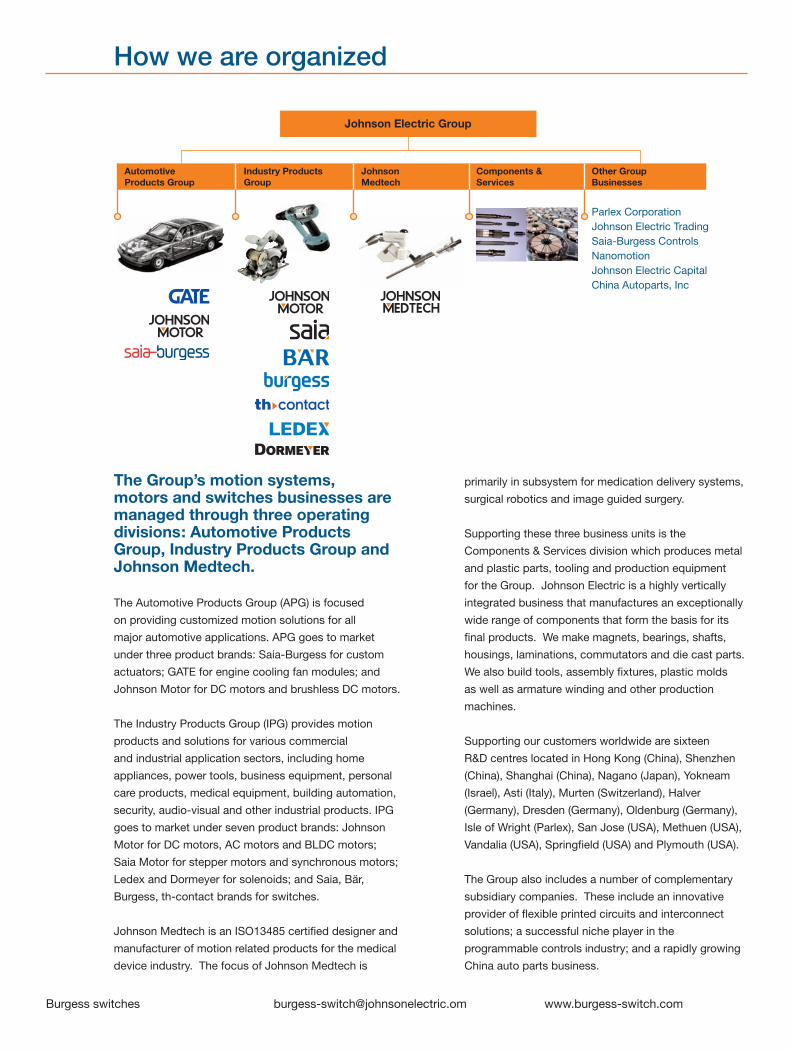
How we are organized
The Group’s motion systems, motors and switches businesses are managed through three operating divisions: Automotive Products Group, Industry Products Group and Johnson Medtech.
The Automotive Products Group (APG) is focused
on providing customized motion solutions for all
major automotive applications. APG goes to market
under three product brands: Saia-Burgess for custom
actuators; GATE for engine cooling fan modules; and
Johnson Motor for DC motors and brushless DC motors.
The Industry Products Group (IPG) provides motion
products and solutions for various commercial
and industrial application sectors, including home
appliances, power tools, business equipment, personal
care products, medical equipment, building automation,
security, audio-visual and other industrial products. IPG
goes to market under seven product brands: Johnson
Motor for DC motors, AC motors and BLDC motors;
Saia Motor for stepper motors and synchronous motors;
Ledex and Dormeyer for solenoids; and Saia, Bär,
Burgess, th-contact brands for switches.
Johnson Medtech is an ISO13485 certified designer and
manufacturer of motion related products for the medical
device industry. The focus of Johnson Medtech is
primarily in subsystem for medication delivery systems,
surgical robotics and image guided surgery.
Supporting these three business units is the
Components & Services division which produces metal
and plastic parts, tooling and production equipment
for the Group. Johnson Electric is a highly vertically
integrated business that manufactures an exceptionally
wide range of components that form the basis for its
final products. We make magnets, bearings, shafts,
housings, laminations, commutators and die cast parts.
We also build tools, assembly fixtures, plastic molds
as well as armature winding and other production
machines.
Supporting our customers worldwide are sixteen
R&D centres located in Hong Kong (China), Shenzhen
(China), Shanghai (China), Nagano (Japan), Yokneam
(Israel), Asti (Italy), Murten (Switzerland), Halver
(Germany), Dresden (Germany), Oldenburg (Germany),
Isle of Wright (Parlex), San Jose (USA), Methuen (USA),
Vandalia (USA), Springfield (USA) and Plymouth (USA).
The Group also includes a number of complementary
subsidiary companies. These include an innovative
provider of flexible printed circuits and interconnect
solutions; a successful niche player in the
programmable controls industry; and a rapidly growing
China auto parts business.
Johnson Electric Group
Automotive Products Group
Industry Products Group
Parlex CorporationJohnson Electric TradingSaia-Burgess ControlsNanomotionJohnson Electric CapitalChina Autoparts, Inc
Other Group Businesses
Components & Services
Johnson Medtech

Look no further.In addition to the wide range of standard products shown in this catalog, we will be happy to work with you to meet your switching needs. If your application requires more than a standard product solution, please consider us early in your design process. Our product development team will be happy to discuss your specification, whether you need a special switch design or a complete value-added assembly. We specialize in developing switches for demanding industrial environments.
The images shown give some examples of our capabilities.
Johnson Electric Group
12 Science Park East Avenue, 6/F
Hong Kong Science Park, Shatin, NT
Hong Kong
Tel : +852 2663 6688
Fax: +852 2897 2054
Website: www.johnsonelectric.com
IPG210/10/E/01
SA
IA S
witch C
atalog
Johnso
n Electric
Johnson Electric Group
Johnson Building, 6-22 Dai Shun Street
Tai Po Industrial Estate, N.T., Hong Kong
Tel : (852) 2663 6688
Fax: (852) 2663 6110
Web Site: www.johnsonelectric.com
IPG230/06/E/01
BÄ
R S
witch C
atalog
Johnso
n Electric
Johnson Electric Group
Johnson Building, 6-22 Dai Shun Street
Tai Po Industrial Estate, N.T., Hong Kong
Tel : (852) 2663 6688
Fax: (852) 2663 6110
Web Site: www.johnsonelectric.com
IPG240/07/E/02
TH
-Co
ntact Pro
duct C
atalog
Johnso
n Electric
Building Automation& Security
Industrial Equipment& Automation
Looking for a specialized switching solution?
Look no further:
In addition to the wide range of standard products shown in Johnson Electric catalogues, we will be happy to work with you to meet your system needs. If your application requires more than a standard product solution, please consider us early in your design process. Our product development team will be happy to discuss your specification, whether you need a special value-added assembly or a complete system. We specialize in developing solutions for medium and high-volume applications.
The images shown give some examples of our capabilities.
Products
Value Added Solutions
Subsystems
Transportation
Home Appliances, White Goods, Floor Care
Power & Garden Tools
Business Machines,Leisure & Fitness
Healthcare & Medical Equipment
[email protected] switches4
Johnson Electric Group
12 Science Park East Avenue, 6/F
Hong Kong Science Park, Shatin, NT
Hong Kong
Tel : +852 2663 6688
Fax: +852 2897 2054
Website: www.johnsonelectric.com
IPG220/10/E/01
Burg
ess Sw
itch Catalo
gJo
hnson E
lectric

Burgess switches [email protected] 5
Burgess is the leading global brand for industrial switches
A pioneer of snap-action technology, the Burgess brand stands for innovative, robust solutions for industrial switch requirements.
Wide rangeSnap-action switches have to fulfill a wide variety of functions. The standard Burgess range ensures there will be a switch for your needs, with one of the broad-est product portfolios around. From ultraminiature to metal-housed basic types, we are sure to have the type appropriate to your application, whether it is signal or power switching, high or low force actuation.
Environmental protectionThe sealed switch is a Burgess speciality. In demanding environments – wet, humid or dusty – even the most sensitive signal can be switched reliably with IP67 rated products. Our robust metal-housed switches offer impact resistance outside whilst switching with precision inside.
Burgess designs have defined industry standards. If you need a specific solution for your switching needs, call us to set your own standard.
Uncompromising reliability With many UL, CSA and ENEC approvals, the perfor-mance of Burgess products is globally recognized. For safety-related applications, such as machine mainte-nance systems, positive-action mechanisms ensure a physical break in the circuit.
Precision actuationSnap-action switches offer high levels of repeat ac-curacy and switch virtually independently of actuation speed and force. This is the mechanism of choice for pressure sensing, timing and position indicating ap-plications.
Minimum sizeOur F5 range demonstrates our capability to switch relatively high current from a small size envelope – 5A 250 VAC from a switch less than 13 mm long.
Typical Burgess switch applications• Circuit breakers• Special purpose vehicles • Vending machines
6 Burgess switches [email protected]
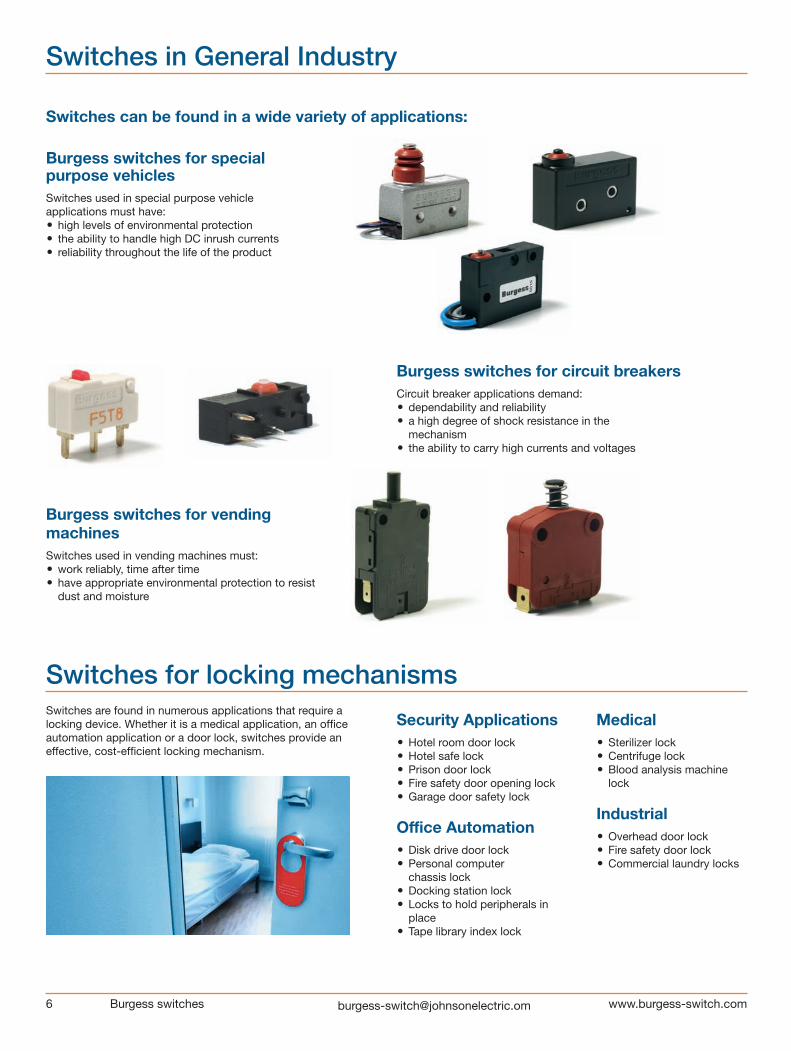
Switches in General Industry
Switches can be found in a wide variety of applications:
Burgess switches for special purpose vehiclesSwitches used in special purpose vehicle applications must have:• high levels of environmental protection• the ability to handle high DC inrush currents• reliability throughout the life of the product
Burgess switches for circuit breakersCircuit breaker applications demand:• dependability and reliability• a high degree of shock resistance in the
mechanism• the ability to carry high currents and voltages
Burgess switches for vending machinesSwitches used in vending machines must:• work reliably, time after time• have appropriate environmental protection to resist
dust and moisture
Switches for locking mechanismsSwitches are found in numerous applications that require a locking device. Whether it is a medical application, an office automation application or a door lock, switches provide an effective, cost-efficient locking mechanism.
Security Applications• Hotel room door lock• Hotel safe lock• Prison door lock• Fire safety door opening lock• Garage door safety lock
Office Automation• Disk drive door lock• Personal computer
chassis lock• Docking station lock• Locks to hold peripherals in
place• Tape library index lock
Medical• Sterilizer lock• Centrifuge lock• Blood analysis machine
lock
Industrial• Overhead door lock• Fire safety door lock• Commercial laundry locks
Burgess switches [email protected] 7
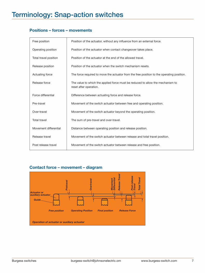
Positions – forces – movements
Free position Position of the actuator, without any influence from an external force.
Operating position Position of the actuator when contact changeover takes place.
Total travel position Position of the actuator at the end of the allowed travel.
Release position Position of the actuator when the switch mechanism resets.
Actuating force The force required to move the actuator from the free position to the operating position.
Release force The value to which the applied force must be reduced to allow the mechanism to reset after operation.
Force differential Difference between actuating force and release force.
Pre-travel Movement of the switch actuator between free and operating position.
Over-travel Movement of the switch actuator beyond the operating position.
Total travel The sum of pre-travel and over-travel.
Movement differential Distance between operating position and release position.
Release travel Movement of the switch actuator between release and total travel position.
Post release travel Movement of the switch actuator between release and free position.
Terminology: Snap-action switches
Contact force – movement – diagram
Actuator orauxiliary actuator
Guide
Free position Operating Position Final position Release Force
Operation of actuator or auxiliary actuator
Pre
trav
el
Ove
rtra
vel
Mov
emen
tD
iffe
ren
tial
Rel
ease
Tra
vel
Pos
t-re
leas
eTr
avel
Tota
l Tra
vel
8 Burgess switches [email protected]
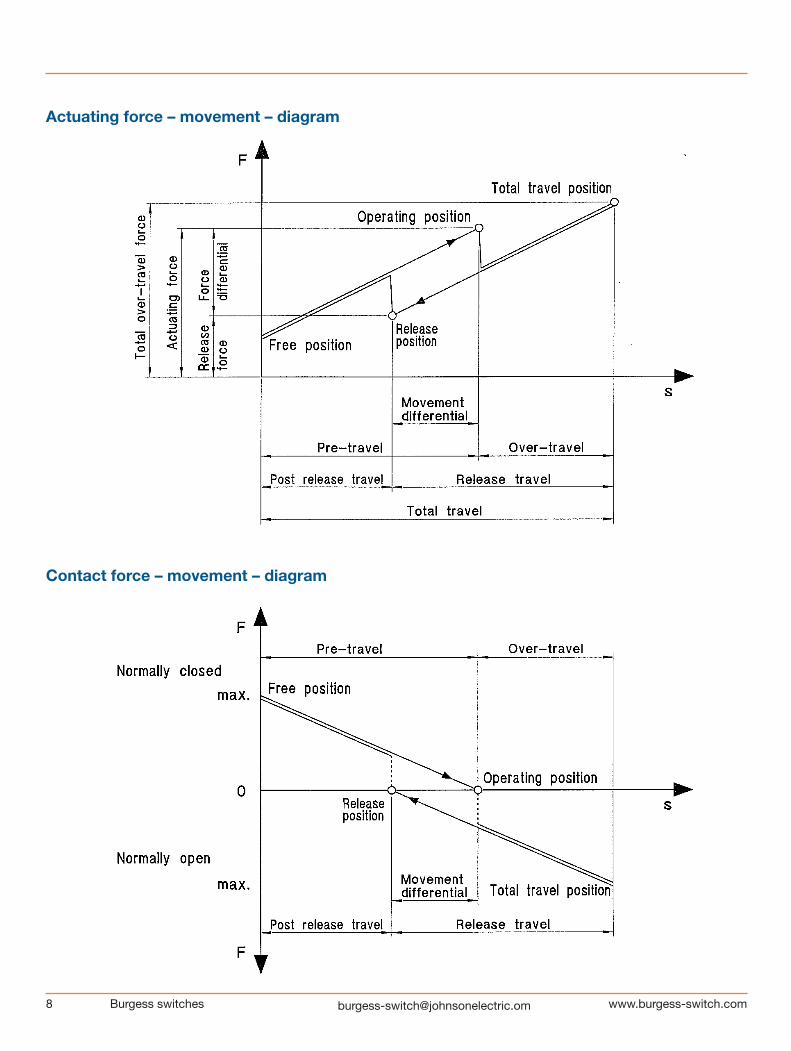
Contact force – movement – diagram
Actuating force – movement – diagram

Burgess switches [email protected] 9
Switch Technology
Clearance Distance – the distance in air between current carrying parts of opposite polarity or between any current carrying part and an earthed-(grounded) metal plate to which the switch is attached.
Creepage Distance – the path along the surface of insulating material between current carrying parts of opposite polarity or between any current carrying part and an earthed (grounded) metal plate to which the switch is attached.
Insulation Resistance – resistance as measured between the normally closed terminals, or between all terminals connected together and a metal plate to which the switch is mounted. In dry conditions the value would be expected to be greater than 5Mh.
Single Throw – a switch which provided an ON-OFF or OFF-ON function but does not change over from one conductor to another. Such switches are usually referred to as being «normally-closed only» or «normally-open only».
Switching Cycle – one complete switching operating from free position into overtravel and back through release position to free position.
Switch Resistance – a total resistance offered by a switch in a circuit, as measured from terminal through mating contacts, to terminal.
Transit Time – the time taken by the moving contact in a snap-action mechanism to move from one stable position to another.
Electrical Ratings
Electrical ratings given in the catalog are ratings according to UL1054, CSA22.55 or IEC61058-1.Where these are not available, a general rating is given based upon in-house laboratory testing.
The ratings tables should be considered as safe working maximums for most applications. How ever, switch performance is influenced by a variety of factors, including:
▪ Frequency of operation▪ Type of load▪ Amount of travel used▪ Temperature▪ Humidity
Please do not hesitate to contact Burgess about your specific application.
Approvals
Switch Life
a. Electrical Life – the electrical life data contained in this catalog is based on laboratory controlled tests. In practice, frequency and speed of operation, type of load, suppres-sion, actuator travel used, ambient humidity and tempera-ture and other environmental conditions can have a major effect on switch life.Individual assessments for specific applications are possible and can be undertaken by Burgess on request.Please ask Burgess if you would like an assessment for your specific application.
b. Mechanical Life – the figures quoted relate to the number of switching cycles made without an electrical load.
Switch Drawings
All drawings in this catalogue are third angle projection.All dimensions in this catalogue are nominal, except where specifically shown.
CSA mark. Switch meets CSA’s safety standards
UL Recognized Component Mark for Canada and the United States
ENEC Mark. Switch fulfills European EN standards. The two digit number indicates which certification body has issued the ENEC Certificate
CQC Approval (China) is available for certain switches

10 Burgess switches [email protected]
Application TechnologyShock and VibrationIf switches are likely to be subjected to shock or vibration, select models with the highest avail able actuating force.Burgess switches feature low mass mechanisms which are inherently resistant to shock and vibration.If possible, the switches should be mounted so that the line of acceleration is at right angles to the travel of the plunger. The maximum avail able overtravel should be used.
Direct CurrentDirect current (DC) ratings where shown should not be exceeded if destructive arcing and contact welding are to be avoided.Some form of arc suppression is recommended when switches are used in DC circuits containing inductive devices wired in series with the switch and the supply.
Lamp LoadsBecause of the very high inrush currents associated with incandescent lamps, applications should be subject to individual assessment.
Capacitive Loads (including fluorescent lamps)These can generate very high peak currents which can cause contact welding. Applications should be subject to individual assessment.
Inductive LoadsThe general ratings tables included in this catalog provide data for switches used to control inductive circuits at a power factor of 0.5 (EN 0.6; UL 0,7 means HP-Rating 0,5).
Contact MaterialsSilver and silver alloys are the primary contact materials used in Burgess switches.The ratings tables shown refer to switches with silver/silver alloy contacts.Gold contacts should be specified when switches are to be used in low voltage control or logic circuits, especially when long periods of inactivity are expected or when atmo-spheres with a high sulphur content may be encountered.Gold contacts are generally available in two forms; gold plated silver alloy contacts, which can also be used at higher currents or gold alloy cross-point contacts, which are only suitable for switching low currents.
Please ask Burgess if you would like an assessment for your specitic application.
Switch Actuation
Direct OperationActuating plungers should be operated in the direction of their axis. Where this is not possible the use of actuating levers is recommended. For direct actuation the attack angle should not exceed 30°.
Actuating LeversVarious lever types are available for use with Burgess switches. They are generally stainless steel.If roller or cam-follower levers are approached in the reverse direction, care must be taken to ensure that the angle of approach is small enough not to jam the lever.
Actuation by CamsCam-follower levers are particularly well suited for use with plastic actuating cams.Abrupt actuation or release of switch actuators shortens the life of the switches.For this reason cam should preferably provide a continuous movement. Ideally they should be of cyclodal form.
Actuation by sliding cams.
Long roller lever with continuous actuation

Burgess switches [email protected] 11
Environmental Protection
Protection ClassificationsThe protection classes of Burgess switches are in accor-dance with IEC 529 and are covered by just four codes.
IP40Adequate protection against solids such as probing fingers and small wires>1mm. Liquids however can gain access and, unless externally protected, the switches should be mounted in dry or well-sheltered positions.
IP5K4Good protection against solid foreign bodies, including dust and water splashing against the enclosure from any direction.Switches may be used out of doors if sheltered from the worst of the elements or on factory machines subjected to normal washing down procedures.
IP65Complete protection against solids, including dust, and against low pressure jets of water from all directions.
IP6K7Complete protection against solids including dust and against immersion in water at a specific pressure for a specified time.We reserve this code for switches which are factory sealed and tested.Switches should not be immersed in any liquid.
*International IK code indicates protection against mechanical impact regarding to EN 50102.
Working TemperaturesFor details of the working temperatures applicable to individual types, refer to the appropriate specification sheet. Special versions suitable for temperatures outside these ranges may be possible. Please contact us for information.
All quoted temperatures assume stable operation. They do not imply an ability to withstand excessive cycling within the range.
Health & Safety
Burgess has ensured, so far as it is reasonably practicable, that their products are as described in this catalog or in other current company publications, or as specified on Burgess installation drawings. They have been so design ed and constructed as to be safe and without risk to health when installed by suitably qualified personnel in accordance with relevant legislation, codes of practice, regulations (including IEE Wiring Regulations), the installation recommendations offered by the company and the accepted rules of the art. Their usage should be confined within the ratings limita-tions and parameters of-application indicated in this catalog and elsewhere.Please contact us should you need additional information or guidance.
Service Recommendations
MaintenanceBurgess switches are not user-maintainable but they should be kept in a reasonably clean, paint-free condition, especially in the actuator area. Regular checks should be made on mounting security and on the actuating medium to switch actuator relationship.Lubrication or the use of aqueous or chemical cleaning fluids is not recommended.
Installation Recommendations
The following notes are intended merely to stress the most important and general aspects of good switch installation procedure and to provide some helpful additional informa-tion. Safety ConsiderationInstallation should only be carried out by competent personnel.
Switch Positioning and OperationPre-loading of the switch actuator must be avoid ed. The actuating medium must be able to operate the switch through the operating position into overtravel and then to retract far enough to allow the switch to regain its free position.Burgess recommends that the actuating medium should drive the switch into at least 50% of the available over-travel.All ratings tables shown in this catalog are based on the use of all the available overtravel.
12 Burgess switches [email protected]
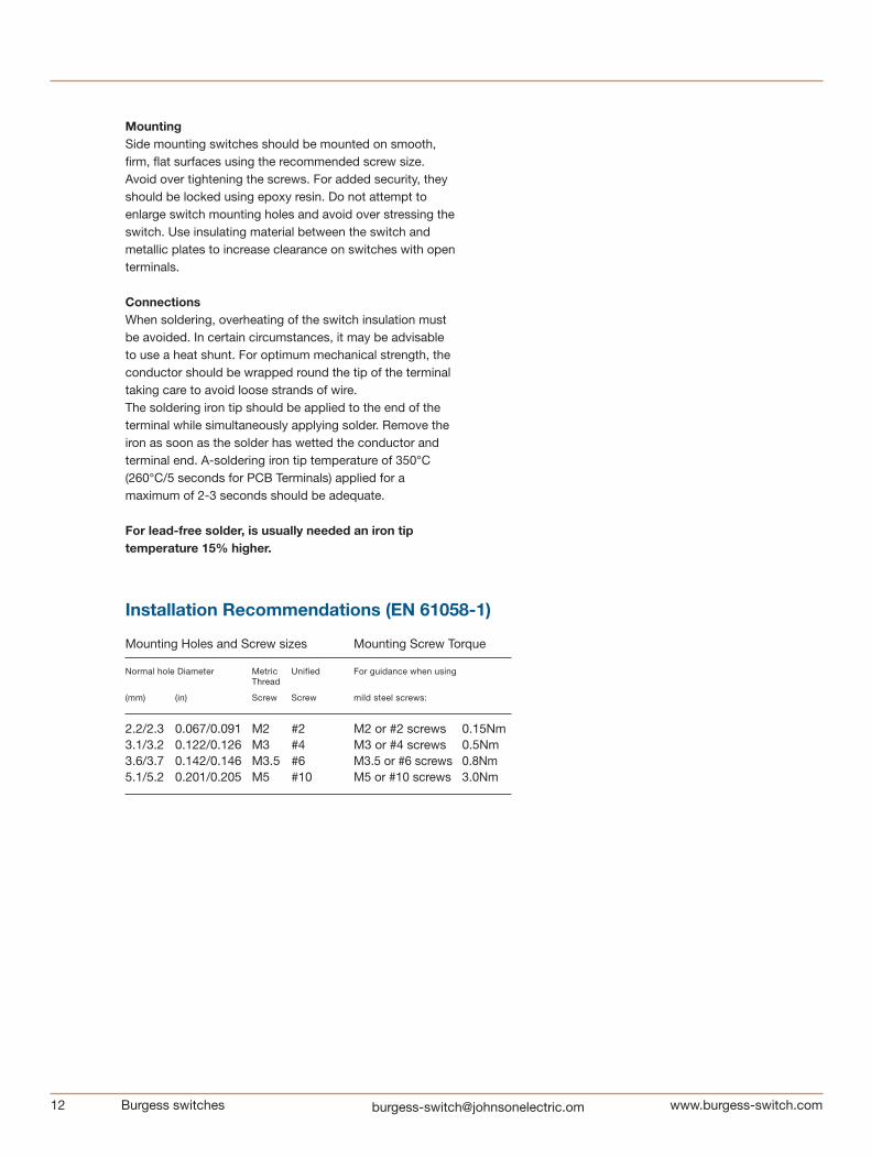
Installation Recommendations (EN 61058-1)
Mounting Holes and Screw sizes Mounting Screw Torque
Normal hole Diameter Metric Unified For guidance when using Thread
(mm) (in) Screw Screw mild steel screws:
2.2/2.3 0.067/0.091 M2 #2 M2 or #2 screws 0.15Nm3.1/3.2 0.122/0.126 M3 #4 M3 or #4 screws 0.5Nm3.6/3.7 0.142/0.146 M3.5 #6 M3.5 or #6 screws 0.8Nm5.1/5.2 0.201/0.205 M5 #10 M5 or #10 screws 3.0Nm
MountingSide mounting switches should be mounted on smooth, firm, flat surfaces using the recommended screw size. Avoid over tightening the screws. For added security, they should be locked using epoxy resin. Do not attempt to enlarge switch mounting holes and avoid over stressing the switch. Use insulating material between the switch and metallic plates to increase clearance on switches with open terminals.
ConnectionsWhen soldering, overheating of the switch insulation must be avoided. In certain circumstances, it may be advisable to use a heat shunt. For optimum mechanical strength, the conductor should be wrapped round the tip of the terminal taking care to avoid loose strands of wire.The soldering iron tip should be applied to the end of the terminal while simultaneously ap plying solder. Remove the iron as soon as the solder has wetted the conductor and terminal end. A-soldering iron tip temperature of 350°C (260°C/5 seconds for PCB Terminals) applied for a maximum of 2-3 seconds should be adequate.
For lead-free solder, is usually needed an iron tip temperature 15% higher.
Burgess switches [email protected] 13
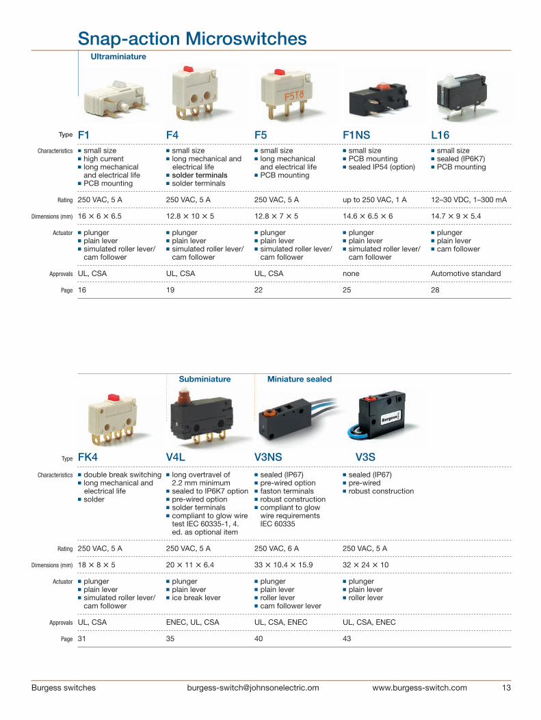
Snap-action Microswitches
■ double break switching■ long mechanical and electrical life■ solder
250 VAC, 5 A
18 • 8 • 5
■ plunger ■ plain lever■ simulated roller lever/
cam follower
UL, CSA
31
Type
Characteristics
Rating
Dimensions (mm)
Actuator
Approvals
Page
Ultraminiature
◼ small size■ high current■ long mechanical
and electrical life■ PCB mounting
250 VAC, 5 A
16 • 6 • 6.5
■ plunger■ plain lever■ simulated roller lever/
cam follower
UL, CSA
16
■ small size■ sealed (IP6K7)■ PCB mounting
12–30 VDC, 1–300 mA
14.7 • 9 • 5.4
■ plunger■ plain lever■ cam follower
Automotive standard
28
FK4 V4L V3NS V3S
Type
Characteristics
Rating
Dimensions (mm)
Actuator
Approvals
Page
Subminiature Miniature sealed
F1 F4 F5 F1NS L16
■ long overtravel of 2.2 mm minimum
■ sealed to IP6K7 option■ pre-wired option ■ solder terminals■ compliant to glow wire
test IEC 60335-1, 4. ed. as optional item
250 VAC, 5 A
20 • 11 • 6.4
■ plunger■ plain lever■ ice break lever
ENEC, UL, CSA
35
■ small size■ PCB mounting■ sealed IP54 (option)
up to 250 VAC, 1 A
14.6 • 6.5 • 6
■ plunger■ plain lever■ simulated roller lever/
cam follower
none
25
■ small size■ long mechanical
and electrical life■ PCB mounting
250 VAC, 5 A
12.8 • 7 • 5
■ plunger■ plain lever■ simulated roller lever/
cam follower
UL, CSA
22
■ small size■ long mechanical and electrical life■ solder terminals■ solder terminals 250 VAC, 5 A
12.8 • 10 • 5
■ plunger■ plain lever■ simulated roller lever/
cam follower
UL, CSA
19
■ sealed (IP67)■ pre-wired■ robust construction
250 VAC, 5 A
32 • 24 • 10
■ plunger■ plain lever■ roller lever
UL, CSA, ENEC 43
■ sealed (IP67)■ pre-wired option ■ faston terminals ■ robust construction ■ compliant to glow
wire requirements IEC 60335
250 VAC, 6 A
33 • 10.4 • 15.9
■ plunger■ plain lever■ roller lever■ cam follower lever
UL, CSA, ENEC 40

Snap-action Microswitches
14 Burgess switches [email protected]
3BR V9N 4BR
■ choice of IP54 or IP67 sealed versions
■ precise movements ■ screw terminals ■ pre-wired option■ long overtravel
250 VAC, 10 A max.
53.1 • 20.6 • 30.8
■ plunger
UL, CSA
52
■ choice of IP54 or IP67 sealed versions
■ precise movements■ metal housing■ pre-wired option■ long overtravel
125 VAC, 10 A max.
53.1 • 20.6 • 29.2
■ plunger
UL, CSA
59
■ sealed (IP67)■ metal housed■ screw terminals ■ pre-wired option
250 VAC, 10 A max.
42 • 24.5 • 16
■ plunger■ plain levers■ reverse action levers■ roller levers
UL, CSA
55
Standard Metal housed
Type
Characteristics
Rating
Dimensions (mm)
Actuator
Approvals
Page
Type
Characteristics
Rating
Dimensions (mm)
Actuator
Approvals
Page
BVM3 KB5 XP XT
Miniature Standard Forced break
■ positive-action forced double break switching
■ > 3 mm contact gap at full travel
■ high electrical rating■ faston terminals
up to 250 V, 25 A
41 • 19.5 • 15.5
■ plunger■ plain lever■ roller lever
ULS, CSA
66
■ positive-action forced break switching
■ > 3 mm contact gap at full travel
■ internationally recognized V3 housing
■ faston terminals
250 VAC, 10 A
28 • 16 • 10.5
■ plunger■ plain lever■ roller lever
ULS, CSA, ENEC
63
■ 8 mm contact gap 8 mm creepage and clearance distances
■ double break contacts
400 VAC, 16.5 A max.
30 • 32 • 12
■ shrouded plunger■ optional key■ plain plunger
UL, cUL, CSA, ENEC
73
■ double break switching■ positive-action force
break option■ > 3 mm contact gap at
full travel option■ faston terminals
400 VAC, 16 A
30 • 32 • 12
■ plain plunger■ mushroom plunger■ plunger with external
spring (for increased reset security)
UL, CSA, ENEC
70

Burgess switches [email protected]
Locknut mounting
Coil spring mechanism Microswitch
[0.26
]
[0.05][0.34]
[0.16]
[0.1]
POSIT
ION
[0.08]
[0.34] [0.2]
[0.63]
[0.19]
[0.02
]
4.0
[0.06]
0.50
[0
.02]
M
AX
[0.09]2.3
[0.16]
4.15 1.40
2.0
[0.0
8]
2.03
1.50
8.6
16.0 MAX
8.60 1.25
Ø 2.0 ± 0.05 [0.08]
Ø 1.
8 ±
0.0
5
Ø 2.
60
[0.07
]
3°
3 EQUI-SPACED RIBSR0.1 [0.04]
POSIT
ION
0.50
5.1
[0.2
]
5.7
[0.2
2]
MAX
3.1
[0.12]
4.85
2.54
[0
.1]
FREE
OPER
ATIN
G
6.5
MAX
1.1[0.04]2.
9[0.
11]
1.35
[0
.05]
F1T8GPUL 1.5X FULL SIZE
ENLARGED VIEW OF PEG
Dimensions
Circuit diagram
16 Burgess switches [email protected]
Ultr
amin
iatu
re
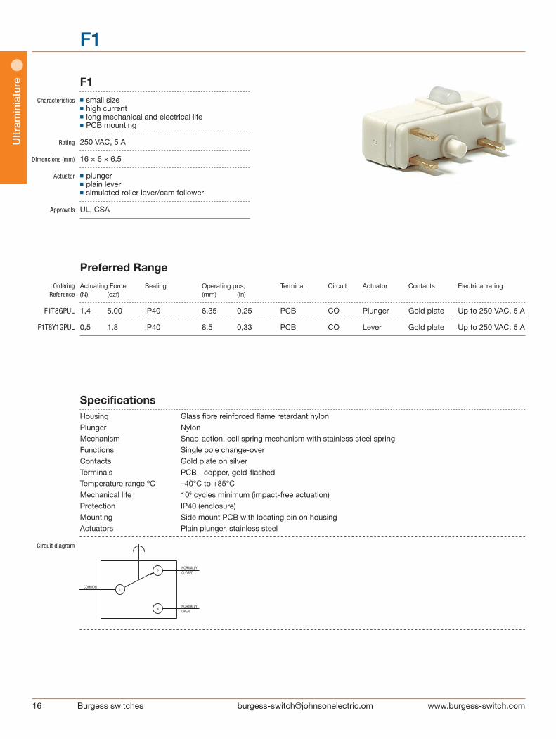
F1
F1 Characteristics ■ small size ■ high current ■ long mechanical and electrical life ■ PCB mounting
Rating 250 VAC, 5 A
Dimensions (mm) 16 × 6 × 6,5
Actuator ■ plunger ■ plain lever ■ simulated roller lever/cam follower
Approvals UL, CSA
Preferred Range Ordering Actuating Force Sealing Operating pos, Terminal Circuit Actuator Contacts Electrical rating Reference (N) (ozf) (mm) (in) F1T8GPUL 1,4 5,00 IP40 6,35 0,25 PCB CO Plunger Gold plate Up to 250 VAC, 5 A
F1T8Y1GPUL 0,5 1,8 IP40 8,5 0,33 PCB CO Lever Gold plate Up to 250 VAC, 5 A
Specifications Housing Glass fibre reinforced flame retardant nylon Plunger Nylon Mechanism Snap-action, coil spring mechanism with stainless steel spring Functions Single pole change-over Contacts Gold plate on silver Terminals PCB - copper, gold-flashed Temperature range ºC –40°C to +85°C Mechanical life 106 cycles minimum (impact-free actuation) Protection IP40 (enclosure) Mounting Side mount PCB with locating pin on housing Actuators Plain plunger, stainless steel
Circuit diagram

Ultram
iniature
17Burgess switches [email protected]
Dimensions
[0.26
]
[0.05][0.34]
[0.16][0.
1]
POSIT
ION
[0.08]
[0.34] [0.2]
[0.63]
[0.19]
[0.02
]
4.0
[0.06]
0.50
[0
.02]
M
AX
[0.09]2.3
[0.16]
4.15 1.40
2.0
[0.0
8]
2.03
1.50
8.6
16.0 MAX
8.60 1.25
Ø 2.0 ± 0.05 [0.08]
Ø 1.
8 ±
0.0
5
Ø 2.
60
[0.07
]
3°
3 EQUI-SPACED RIBSR0.1 [0.04]
POSIT
ION
0.50
5.1
[0.2
]
5.7
[0.2
2]
MAX
3.1
[0.12]
4.85
2.54
[0
.1]
FREE
OPER
ATIN
G
6.5
MAX
1.1[0.04]2.
9[0.
11]
1.35
[0
.05]
F1T8GPUL 1.5X FULL SIZE
ENLARGED VIEW OF PEG
[0.16
]
4.1[0.22
]
5.7
MAX
[0.18]
4.62
POSIT
ION
[0.16]
4.05
FREE
POS
ITIO
N
OPER
ATIN
G
17.93 [0.71]
[0.26
]
[0.05][0.34]
[0.1]
[0.06
]
[0.02
]
[0.06]
0.50
[0
.02]
M
AX
[0.16]
4.15 1.40
2.0
[0.0
8]
1.50
8.6 [0.34]
16.0 [0.63] MAX
8.60 1.25
Ø 2.0 ± 0.05[0.08]
Ø 1.
8 ±
0.0
5
Ø 2.
60
[0.07
]
3°
3 EQUI-SPACED RIBSR0.1 [0.04]
0.50
2.54
[0
.1]
6.5
MAX
1.1[0.04]2.
9[0.
11]
1.35
[0
.05]
F1T8Y1GPUL 1.5X FULL SIZE
ENLARGED VIEW OF PEG
Recommended maximum electrical ratings
Voltage Resistive load Inductive load Approval (max) (A)
250 VAC 5 (0.75 pf) 5 UL 1054/CSA 22.2 No. 55 - 6,000 operations 0 - 15 VDC 5 General rating - 50,000 operations 15 - 30 VDC 3 General rating - 50,000 operations
Operating Characteristics Actuating Release Free Operating Movement Over Actuator Reference Force Force Position Position Differential Travel Maximum Minimum Maximum Maximum (N) (ozf) (N) (ozf) (mm) (in) (mm) (in) (mm) (in) (mm) (in) Plunger F1T8GPUL 1,4 5,00 0,28 1,00 7,1 0,28 6,35 ± 0.38 0,25 ± 0.015 0,1 0,004 *
Straight lever F1T8Y1GPUL 0,5 1,8 0,06 0,022 11,0 0,43 8,5 ± 1,5 0,33 ± 0.06 0,5 0,02 *
Width of lever 4.05 mm/0.16 in * Plunger can be depressed flush with housing. The housing should not be used as an end stop.
1
2
4 1
2
4
17.93 [0.71]
1
2
4 1
2
4
17.93 [0.71]
F1
18 Burgess switches [email protected]
Ultr
amin
iatu
re
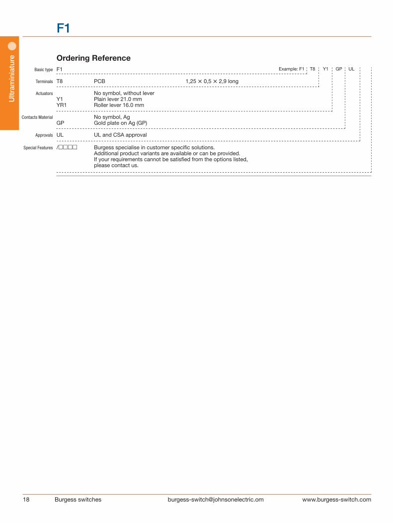
Basic type F1
Terminals T8 PCB 1,25 • 0,5 • 2,9 long
Actuators No symbol, without lever Y1 Plain lever 21.0 mm YR1 Roller lever 16.0 mm
Contacts Material No symbol, Ag GP Gold plate on Ag (GP)
Approvals UL UL and CSA approval Special Features /□□□□ Burgess specialise in customer specific solutions. Additional product variants are available or can be provided. If your requirements cannot be satisfied from the options listed, please contact us.
Ordering Reference Example: F1 T8 Y1 GP UL
F1
Ultram
iniature
19Burgess switches [email protected]
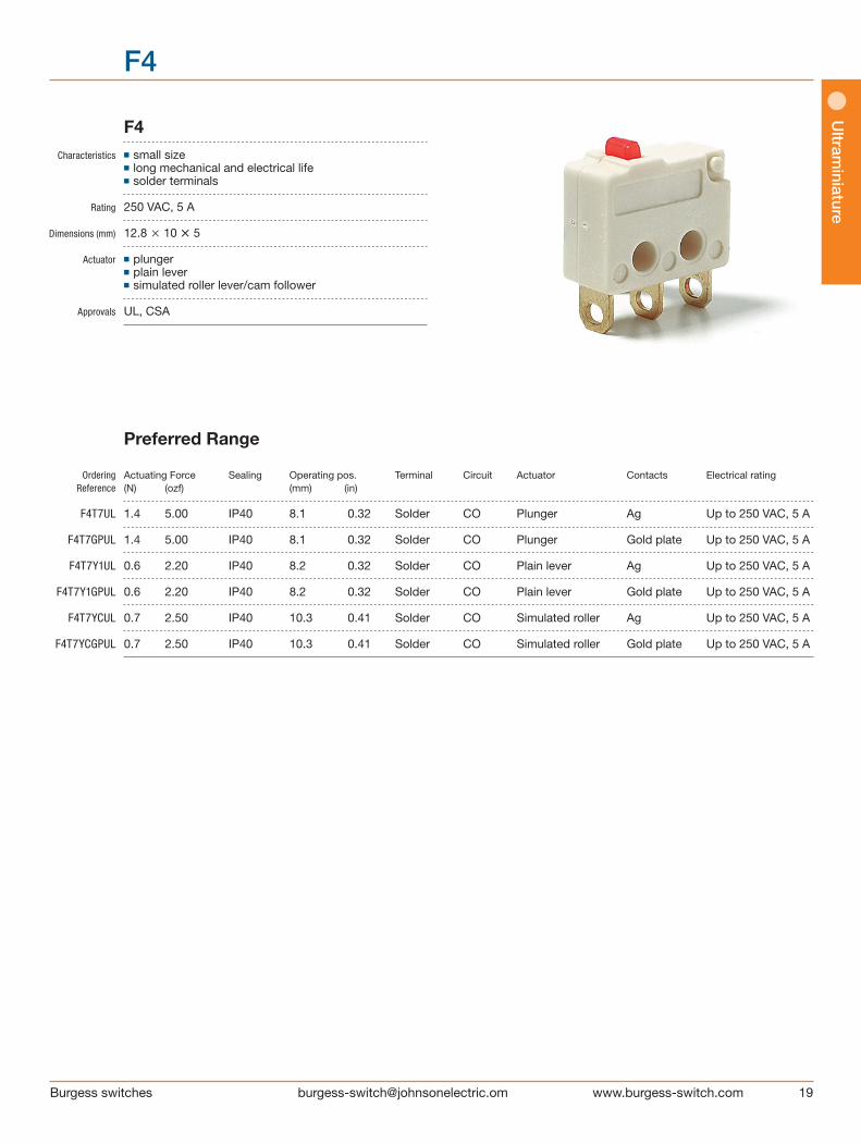
F4
F4 Characteristics ■ small size ■ long mechanical and electrical life ■ solder terminals Rating 250 VAC, 5 A Dimensions (mm) 12.8 × 10 • 5
Actuator ■ plunger ■ plain lever ■ simulated roller lever/cam follower
Approvals UL, CSA
Preferred Range
Ordering Actuating Force Sealing Operating pos. Terminal Circuit Actuator Contacts Electrical rating Reference (N) (ozf) (mm) (in)
F4T7UL 1.4 5.00 IP40 8.1 0.32 Solder CO Plunger Ag Up to 250 VAC, 5 A
F4T7GPUL 1.4 5.00 IP40 8.1 0.32 Solder CO Plunger Gold plate Up to 250 VAC, 5 A
F4T7Y1UL 0.6 2.20 IP40 8.2 0.32 Solder CO Plain lever Ag Up to 250 VAC, 5 A
F4T7Y1GPUL 0.6 2.20 IP40 8.2 0.32 Solder CO Plain lever Gold plate Up to 250 VAC, 5 A
F4T7YCUL 0.7 2.50 IP40 10.3 0.41 Solder CO Simulated roller Ag Up to 250 VAC, 5 A
F4T7YCGPUL 0.7 2.50 IP40 10.3 0.41 Solder CO Simulated roller Gold plate Up to 250 VAC, 5 A

20 Burgess switches [email protected]
Ultr
amin
iatu
re
F4
Specifications Housing Glass fibre reinforced flame retardent nylon Plunger Nylon Mechanism Snap-action, single pole Functions Change-over, Normally open, Normally closed Contacts Fixed, Moving – Ag or Gold plate on Ag Terminals 2.0 mm (0.08 in) faston and solder - brass, gold flashed Temperature range ºC -40°C to +85°C Mechanical life 107 cycles minimum (impact free actuation) Protection IP 40 (enclosure) Mounting Side mounting Actuators Plain lever, simulated roller lever/cam follower, stainless steel Accessories Lug mounting frame, insulating sheet, spring-leaf actuator
Circuit diagram
Dimensions
Recommended maximum electrical ratings
Voltage Load Approval (max) (A)
250 VAC 5 (0.75 pf) UL 1054/CSA 22.2 No. 55 - 6,000 operations 125 VAC 5 (0.75 pf) UL 1054/CSA 22.2 No. 55 - 6,000 operations 0 - 15 VDC 5 General rating - 50,000 operations 15 - 30 VDC 3 General rating - 50,000 operations
1
4
2
COMMON
OPEN
NORMALLY
CLOSED
NORMALLY
F4T7
Mounting holes
Fre
e p
osi
tion
OP

Ultram
iniature
21Burgess switches [email protected]
F4
Operating Characteristics Actuating Release Free Operating Movement Over Actuator Reference Force Force Position Position Differential travel Maximum Minimum Maximum Maximum (N) (ozf) (N) (ozf) (mm) (in) (mm) (in) (mm) (in) Plunger F4T7 1,4 5,00 0,25 0,90 8,8 0,35 8,1 +0.3 0,32 +0.01 0,13 0,005 * –0.2 –0.008 Y1-Lever F4T7Y1 0,6 2,20 0,07 0,25 10,0 0,39 8,2 +1.0 0,32 +0.04 0,70 0,030 * –0.7 –0.03
Width of lever 3.0 mm/0.12 in
YC-Lever F4T7YC 0,7 2,50 0,09 0,32 11,7 0,46 10,3 +0.8 0,41 +0.03 0,45 0,020 * –0.55 –0.02
Width of lever 3.0 mm/0.12 in
Operating characteristics are specified from the mounting holes. * Plunger can be depressed flush with housing. The hous ing should not be used as an end stop.
Basic type F4 Terminals T7 Solder 3.50 • 0.5 • 3.6 long
Circuit No symbol, change-over
Actuators No symbol, without lever Y1 Plain lever 21.0 mm YC Cam follower lever 16.9 mm Contacts Material No symbol, Ag GP Gold plate on Ag (GP)
Approvals No symbol, without approval UL UL and CSA approval Special Features /□□□□ Burgess specialise in customer specific solutions. Additional product variants are available or can be provided. If your requirements cannot be satisfied from the options listed, please contact us.
Ordering Reference Example: F4 T7 Y1 GP UL

22 Burgess switches [email protected]
F5
F5 Characteristics ■ small size ■ long mechanical and electrical life ■ PCB mounting
Rating 250 VAC, 5 A
Dimensions (mm) 12.8 • 7 • 5
Actuator ■ plunger ■ plain lever ■ simulated roller lever/cam follower
Approvals UL, CSA
Preferred Range
Ordering Actuating Force Sealing Operating pos. Terminal Circuit Actuator Contacts Electrical rating Reference (N) (ozf) (mm) (in)
F5T8UL 1.4 5.00 IP40 8.75 0.34 PCB CO Plunger Ag Up to 250 VAC, 5 A
F5T8GPUL 1.4 5.00 IP40 8.75 0.34 PCB CO Plunger Gold plate Up to 250 VAC, 5 A
F5T8Y1UL 0.6 2.20 IP40 8.80 0.35 PCB CO Plain lever Ag Up to 250 VAC, 5 A
F5T8Y1GPUL 0.6 2.20 IP40 8.80 0.35 PCB CO Plain lever Gold plate Up to 250 VAC, 5 A
F5T8YCUL 0.7 2.50 IP40 10.90 0.43 PCB CO Simulated roller Ag Up to 250 VAC, 5 A
F5T8YCGPUL 0.7 2.50 IP40 10.90 0.43 PCB CO Simulated roller Gold plate Up to 250 VAC, 5 A
Ultr
amin
iatu
re

Ultram
iniature
23Burgess switches [email protected]
F5
Specifications Housing Glass fibre reinforced flame retardent nylon Plunger Nylon Mechanism Snap-action, single pole Functions Change-over, Normally open, Normally closed Contacts Fixed, Moving - Silver or Gold plate on silver Terminals PCB - Brass, gold flashed Temperature range ºC -40°C to +85°C Mechanical life 107 cycles minimum (impact free actuation) Protection IP 40 (enclosure) Mounting PCB Actuators Plain lever, simulated roller lever/cam follower, stainless steel
Circuit diagram
Dimensions
1
4
2
COMMON
OPEN
NORMALLY
CLOSEDNORMALLY
Recommended maximum electrical ratings
Voltage Load Approval (max) (A)
250 VAC 5 (0.75 pf) UL 1054/CSA 22.2 No. 55 - 6,000 operations 125 VAC 5 (0.75 pf) UL 1054/CSA 22.2 No. 55 - 6,000 operations 0 - 15 VDC 5 General rating - 50,000 operations 15 - 30 VDC 1 General rating - 50,000 operations
24 Burgess switches [email protected]
F5
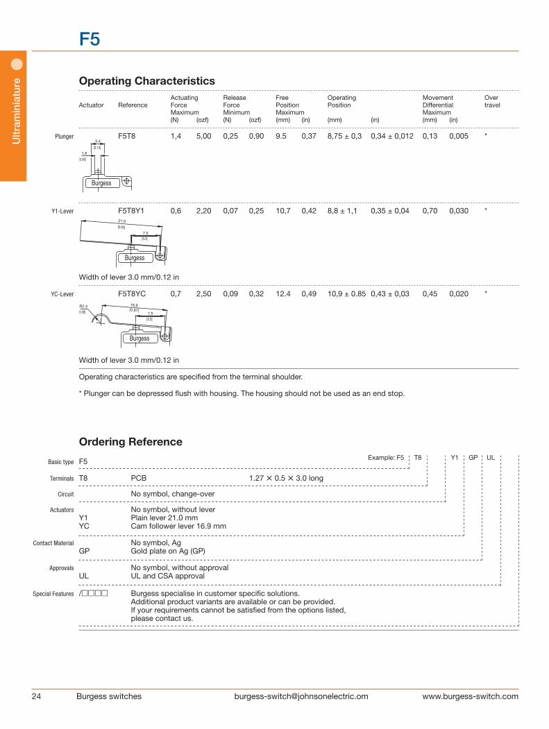
Operating Characteristics Actuating Release Free Operating Movement Over Actuator Reference Force Force Position Position Differential travel Maximum Minimum Maximum Maximum (N) (ozf) (N) (ozf) (mm) (in) (mm) (in) (mm) (in)
Plunger F5T8 1,4 5,00 0,25 0,90 9.5 0,37 8,75 ± 0,3 0,34 ± 0,012 0,13 0,005 *
Y1-Lever F5T8Y1 0,6 2,20 0,07 0,25 10,7 0,42 8,8 ± 1,1 0,35 ± 0,04 0,70 0,030 *
Width of lever 3.0 mm/0.12 in
YC-Lever F5T8YC 0,7 2,50 0,09 0,32 12.4 0,49 10,9 ± 0.85 0,43 ± 0,03 0,45 0,020 *
Width of lever 3.0 mm/0.12 in
Operating characteristics are specified from the terminal shoulder. * Plunger can be depressed flush with housing. The hous ing should not be used as an end stop.
Basic type F5
Terminals T8 PCB 1.27 • 0.5 • 3.0 long
Circuit No symbol, change-over
Actuators No symbol, without lever Y1 Plain lever 21.0 mm YC Cam follower lever 16.9 mm Contact Material No symbol, Ag GP Gold plate on Ag (GP)
Approvals No symbol, without approval UL UL and CSA approval
Special Features /□□□□ Burgess specialise in customer specific solutions. Additional product variants are available or can be provided. If your requirements cannot be satisfied from the options listed, please contact us.
Ordering Reference Example: F5 T8 Y1 GP UL
Ultr
amin
iatu
re
Ultram
iniature
25Burgess switches [email protected]
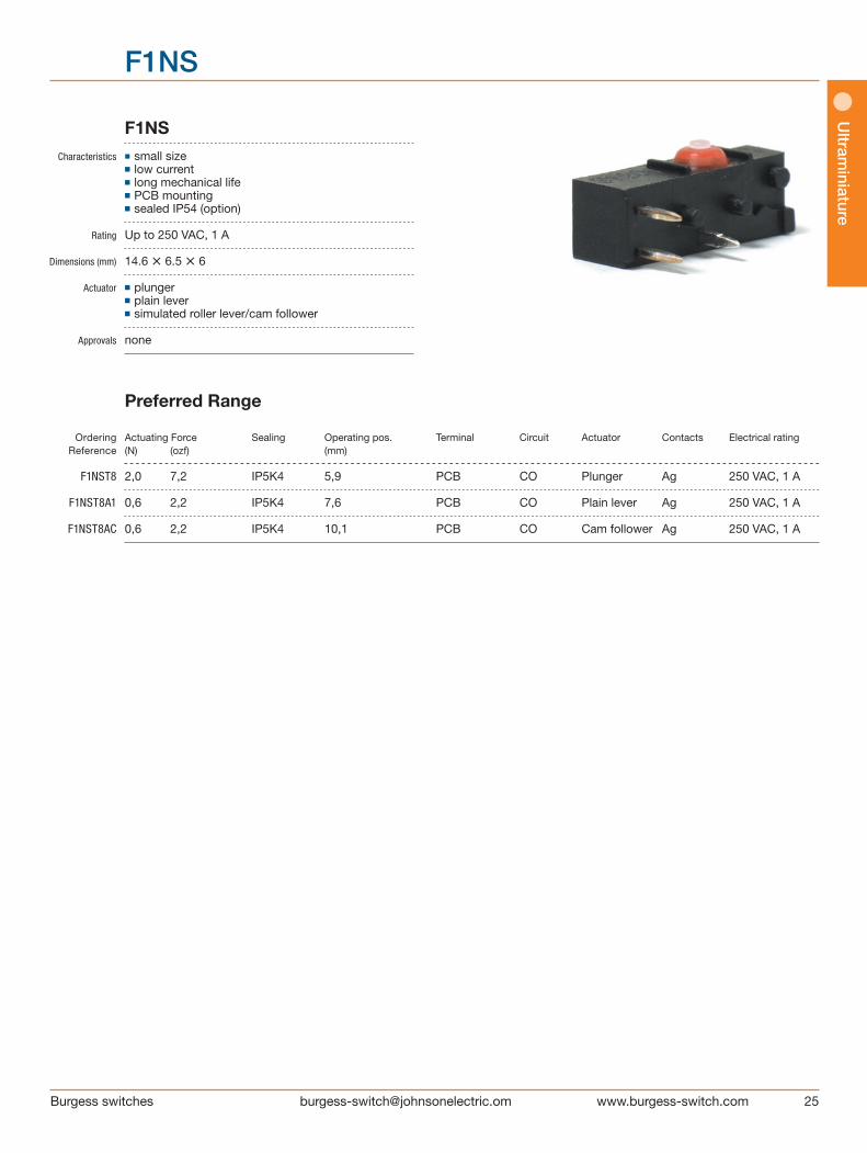
F1NS Characteristics ◼ small size ■ low current ■ long mechanical life ■ PCB mounting ■ sealed IP54 (option)
Rating Up to 250 VAC, 1 A
Dimensions (mm) 14.6 • 6.5 • 6
Actuator ■ plunger ■ plain lever ■ simulated roller lever/cam follower
Approvals none
Preferred Range
Ordering Actuating Force Sealing Operating pos. Terminal Circuit Actuator Contacts Electrical rating Reference (N) (ozf) (mm)
F1NST8 2,0 7,2 IP5K4 5,9 PCB CO Plunger Ag 250 VAC, 1 A
F1NST8A1 0,6 2,2 IP5K4 7,6 PCB CO Plain lever Ag 250 VAC, 1 A
F1NST8AC 0,6 2,2 IP5K4 10,1 PCB CO Cam follower Ag 250 VAC, 1 A
F1NS

26 Burgess switches [email protected]
Ultr
amin
iatu
re Specifications Housing Base: PA 6.6; Cowl: Silicon; Lid: PA 6.6 Plunger POM Mechanism Snap-action, coil spring mechanism with stainless steel spring. Single-pole change-over contact Contacts Fine silver, Gold plate on silver Terminals PCB - Phosphor Bronze silver plated Temperature range ºC –40°C bis +85°C Mechanical life 107 cycles minimum (impact-free actuation) Protection Enclosure IP40 (F1N), IP54 (F1NS) Mounting PCB. Locating pins on housing
Circuit diagram
Dimensions
14,6 MAX(.58)
2.8±0.15
Recommended maximum electrical ratings
Voltage Resistive load Inductive load Voltage Resistive load Inductive load (VAC) (A) (A) (VDC) (A) (A)
125 1 1 up to 250 1 1 30 2 2 50 0,5 0,5 75 0,25 0,25 125 0,2 0,03
4.8
F1NS
COMMONNORMALLY
NORMALLY
CLOSED
OPEN

Ultram
iniature
27Burgess switches [email protected]
Operating Characteristics Actuating Release Free Operating Movement Total travelled Actuator Reference Force Force Position Position Differential position Maximum Minimum Maximum Maximum Maximum (N) (ozf) (N) (ozf) (mm) (in) (mm) (in) (mm) (in) (mm) (in)
Plunger F1NST8 2 7,20 0,2 0,72 6,5 0,26 5,9 ± 0,2 0,23 ± 0,008 0,2 0,008 * A1-Lever F1NST8A1 0,6 2,20 0,09 0,32 10,5 0,41 7,6 ± 1,2 0,3 ± 0,05 0,7 0,03 * Width of lever 3 mm/0,12 in
AC-Lever F1NST8AC 0,6 2,20 0,09 0,32 13,3 0,52 10,1 ± 1,2 0,4 ± 0,05 0,7 0,03 *
Width of lever 3 mm/0,12 in
Datum for Free Position and Operating Position: base of switch opposite plunger.
* Flush with case. The case should not be used as an end stop.
Basic type F1N
Type of sealing No symbol, unsealed S Sealed IP5K4
Terminals T8 PCB 0.8 • 0.5 • 3.45 long
Circuit No symbol, change-over
Actuators No symbol, without lever A Special lever A type (see specification) A1 Plain lever 18.0 mm AC Cam follower lever 18.5 mm
Contact Material No symbol, Ag AU Gold on nickel GP Gold plate on Ag (GP) Special Features /□□□□ Burgess specialise in customer specific solutions. Additional product variants are available or can be provided. If your requirements cannot be satisfied from the options listed, please contact us.
Ordering Reference
Example: F1N S T8 A AU
F1NS
28 Burgess switches [email protected]
Ultr
amin
iatu
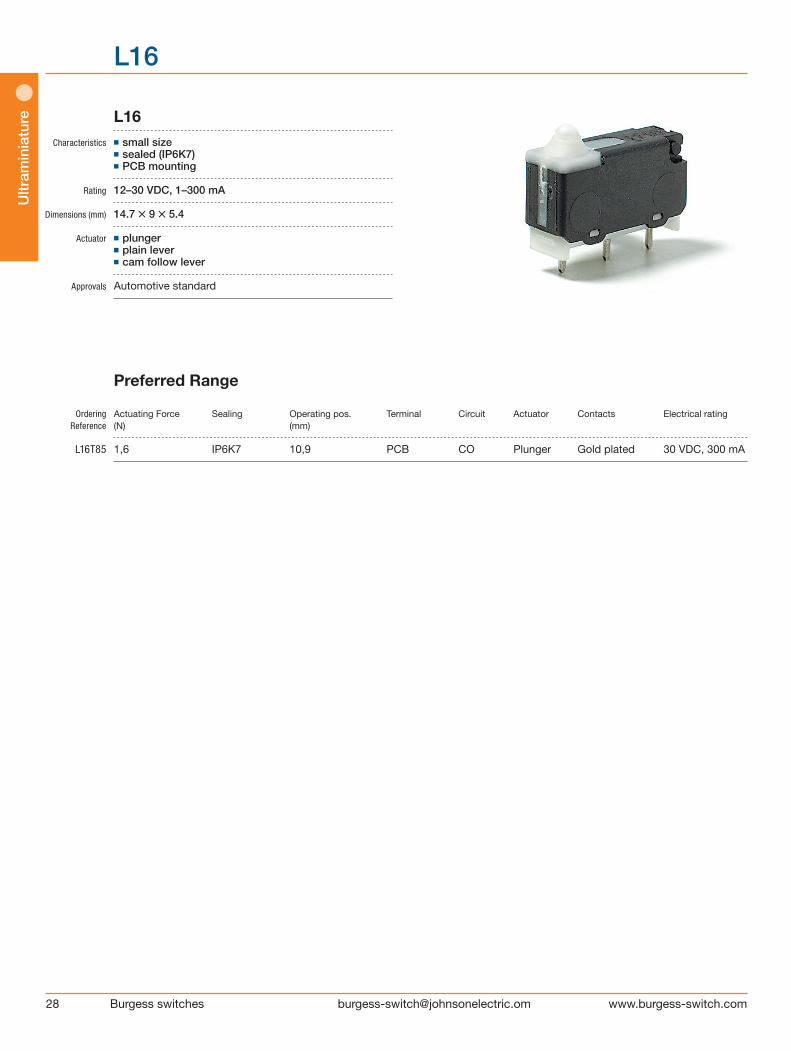
re L16 Characteristics ■ small size ■ sealed (IP6K7) ■ PCB mounting
Rating 12–30 VDC, 1–300 mA
Dimensions (mm) 14.7 • 9 • 5.4
Actuator ■ plunger ■ plain lever ■ cam follow lever
Approvals Automotive standard
Preferred Range
Ordering Actuating Force Sealing Operating pos. Terminal Circuit Actuator Contacts Electrical rating Reference (N) (mm)
L16T85 1,6 IP6K7 10,9 PCB CO Plunger Gold plated 30 VDC, 300 mA
L16
Ultram
iniature
29Burgess switches [email protected]
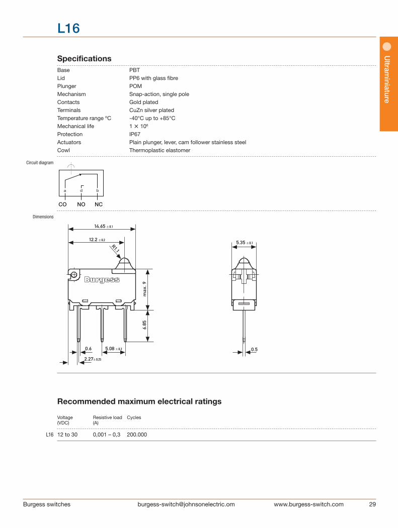
Specifications Base PBT Lid PP6 with glass fibre Plunger POM Mechanism Snap-action, single pole Contacts Gold plated Terminals CuZn silver plated Temperature range ºC -40°C up to +85°C Mechanical life 1 • 106
Protection IP67 Actuators Plain plunger, lever, cam follower stainless steel Cowl Thermoplastic elastomer
Circuit diagram
Dimensions
Recommended maximum electrical ratings
Voltage Resistive load Cycles (VDC) (A)
L16 12 to 30 0,001 – 0,3 200.000
a b d
CO NO NC
L16

30 Burgess switches [email protected]
Ultr
amin
iatu
re Operating Characteristics Actuating Release Free Operating Movement Total travelled Actuator Reference Force Force Position Position Differential positions Maximum Minimum Maximum Maximum Minimum (N) (N) (mm) (mm) (mm) (mm)
Plunger F6T85 1,6 0,2 11.5 10.95 ± 0.25 0,3 9.6
H-Lever F6T85H For positions and forces of this actuator please contact Saia Burgess 2,5 0,5 13,00 11,4 + 0,55 0,45 10.1
Width of lever 3.0 mm/0.12 in
Datum for free position and operating position is button edge of base (stand-off’s). The case should not be used as an end stop.
Basic type F6
Terminals T8 PCB 0.6 • 0.5 • 4.0 long T81 Formed PCB 0.6 • 0.5 • 2.35 long (Side mount L.H. plunger end) T82 Formed PCB 0.6 • 0.5 • 2.85 long (Side mount R.H. plunger end) T84 Short PCB 0.6 • 0.5 • 2.0 long T85 Long PCB 0.6 • 0.5 • 6.85 long
Circuit No symbol, change-over Actuators No symbol, without lever H Formed. lever 0.3 mm thickness Y1 Plain lever 21 mm YC Cam follower lever 16.9 mm HC Cam follower
Contact Material No symbol, Ag, gold plated
Special Features /□□□□ Burgess specialise in customer specific solutions. Additional product variants are available or can be provided. If your requirements cannot be satisfied from the options listed, please contact us.
Ordering Reference Example: F6 T8 H
L16
Ultram
iniature
31Burgess switches [email protected]
FK4
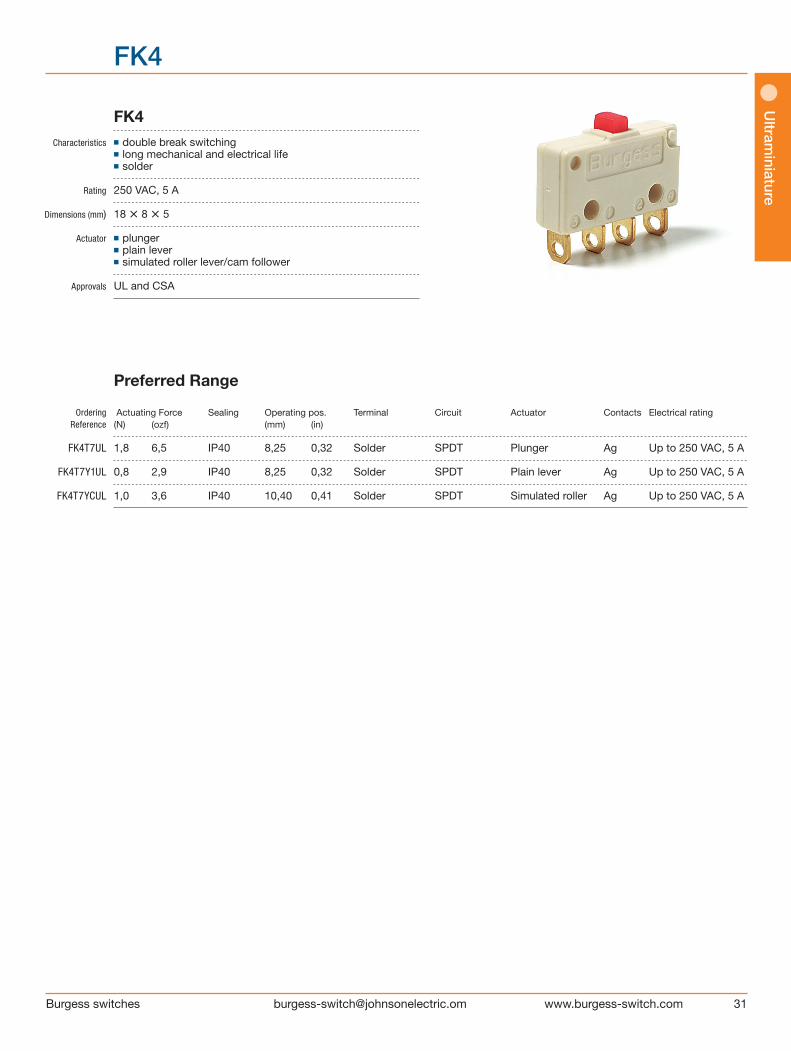
FK4 Characteristics ■ double break switching ■ long mechanical and electrical life ■ solder
Rating 250 VAC, 5 A Dimensions (mm) 18 • 8 • 5
Actuator ■ plunger ■ plain lever ■ simulated roller lever/cam follower
Approvals UL and CSA
Preferred Range
Ordering Actuating Force Sealing Operating pos. Terminal Circuit Actuator Contacts Electrical rating Reference (N) (ozf) (mm) (in)
FK4T7UL 1,8 6,5 IP40 8,25 0,32 Solder SPDT Plunger Ag Up to 250 VAC, 5 A
FK4T7Y1UL 0,8 2,9 IP40 8,25 0,32 Solder SPDT Plain lever Ag Up to 250 VAC, 5 A
FK4T7YCUL 1,0 3,6 IP40 10,40 0,41 Solder SPDT Simulated roller Ag Up to 250 VAC, 5 A

32 Burgess switches [email protected]
Ultr
amin
iatu
re
FK4
Burgess
±0.05
[0.04
][0.
16]
1.0
4.0
0.8±0.05
[0.2]
[0.02
]
[0.03
]
3.0
5.1 MAX
[0.12]
[0.09
]
[0.05]
[0.18]
[0.19]
2.5
4.6
[0.1]
4.77
POSIT
ION
[0.2][0.02]
[0.38]
[0.69]
[0.2]
9.53
5.08 0.50
2 MOUNTING HOLES
Ø2.25 0.0 [0.09]+0.1
1.18
[0.05]
FREE
POS
ITIO
N
OPER
ATIN
G
0.50
7.7
MAX
2.35
M
AX
5.08 1.18
17.6 MAX
4213
NORMALLY
OPEN
NORMALLY
CLOSED
4
21
3
Specifications Housing Glass fibre reinforced flame retardent nylon Plunger Nylon Mechanism Double pole, single throw snap-action coil spring mechanism with stainless steel springs Functions Change-over, NO, NC Contacts Silver Terminals Solder, PCB - brass, gold flashed Temperature range ºC –40°C to +85°C Mechanical life 107 cycles minimum (impact free actuation) Protection IP40 (enclosure) Mounting Side mounting or PCB mounting (T8 only) Actuators Plain lever, simulated roller lever/cam follower, stainless steel
Circuit diagram
Dimensions
Recommended maximum electrical ratings
Voltage Load Approval (max) (A)
250 VAC 5 (0.75 pf) UL 1054/CSA 22.2 No. 55 - 6,000 operations 125 VAC 5 (0.75 pf) UL 1054/CSA 22.2 No. 55 - 6,000 operations 0 - 15 VDC 5 General rating - 50,000 operations 15 - 30 VDC 3 General rating - 50,000 operations
Values shown are recommended maximum ratings for single circuit switching
Ultram
iniature
33Burgess switches [email protected]
FK4
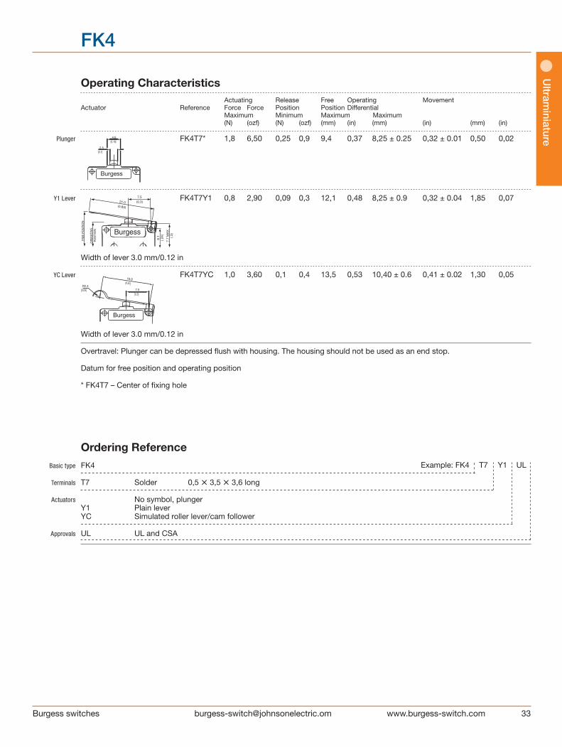
Operating Characteristics Actuating Release Free Operating Movement Actuator Reference Force Force Position Position Differential Maximum Minimum Maximum Maximum (N) (ozf) (N) (ozf) (mm) (in) (mm) (in) (mm) (in)
Plunger FK4T7* 1,8 6,50 0,25 0,9 9,4 0,37 8,25 ± 0.25 0,32 ± 0.01 0,50 0,02
Y1 Lever FK4T7Y1 0,8 2,90 0,09 0,3 12,1 0,48 8,25 ± 0.9 0,32 ± 0.04 1,85 0,07
Width of lever 3.0 mm/0.12 in
YC Lever FK4T7YC 1,0 3,60 0,1 0,4 13,5 0,53 10,40 ± 0.6 0,41 ± 0.02 1,30 0,05
Width of lever 3.0 mm/0.12 in
Overtravel: Plunger can be depressed flush with housing. The housing should not be used as an end stop.
Datum for free position and operating position * FK4T7 – Center of fixing hole
R2.4
BurgessBurgessBurgess
[0.83] [0.67]
[0.09][0.3]
16.9
7.5[0.3]
21.0
7.5
[0.18]
[0.1]
4.6
2.5
R2.4
BurgessBurgessBurgess
[0.83] [0.67]
[0.09][0.3]
16.9
7.5[0.3]
21.0
7.5
[0.18]
[0.1]
4.6
2.5
Basic type FK4
Terminals T7 Solder 0,5 • 3,5 • 3,6 long
Actuators No symbol, plunger Y1 Plain lever YC Simulated roller lever/cam follower
Approvals UL UL and CSA
Ordering Reference Example: FK4 T7 Y1 UL

Long overtravel Microswitches
Circuit diagram
Dimensions
COMMON(black)
NORMALLYCLOSED(grey)
NORMALLYOPEN(blue)
35Burgess switches [email protected]
Sub
miniature
V4L
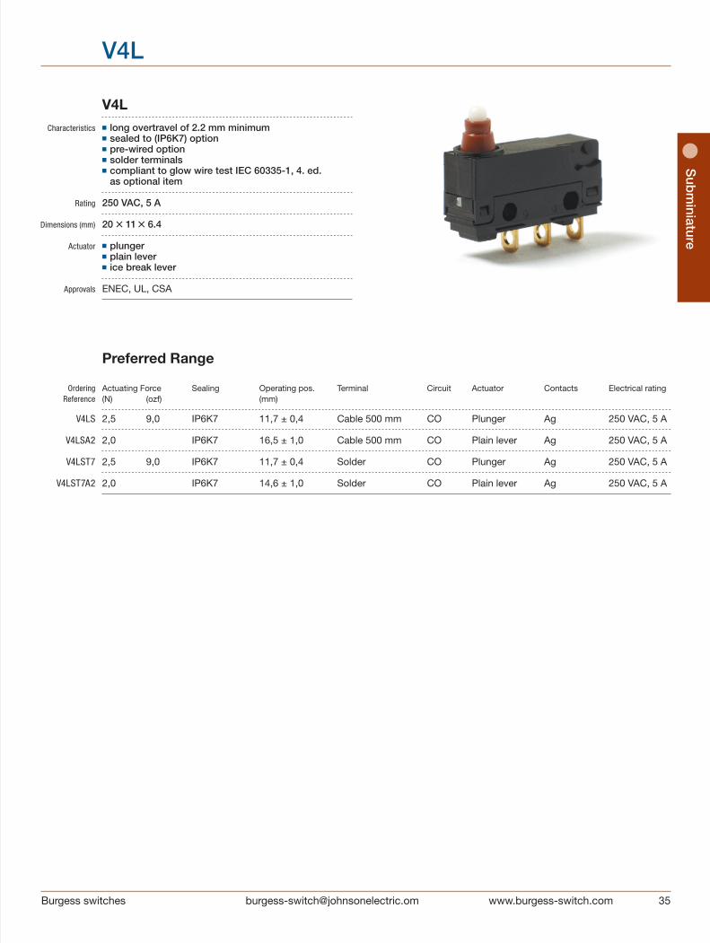
V4L Characteristics ■ long overtravel of 2.2 mm minimum ■ sealed to (IP6K7) option ■ pre-wired option ■ solder terminals ■ compliant to glow wire test IEC 60335-1, 4. ed.
as optional item
Rating 250 VAC, 5 A Dimensions (mm) 20 • 11 • 6.4
Actuator ■ plunger ■ plain lever ■ ice break lever
Approvals ENEC, UL, CSA
Preferred Range
Ordering Actuating Force Sealing Operating pos. Terminal Circuit Actuator Contacts Electrical rating Reference (N) (ozf) (mm)
V4LS 2,5 9,0 IP6K7 11,7 ± 0,4 Cable 500 mm CO Plunger Ag 250 VAC, 5 A
V4LSA2 2,0 IP6K7 16,5 ± 1,0 Cable 500 mm CO Plain lever Ag 250 VAC, 5 A
V4LST7 2,5 9,0 IP6K7 11,7 ± 0,4 Solder CO Plunger Ag 250 VAC, 5 A
V4LST7A2 2,0 IP6K7 14,6 ± 1,0 Solder CO Plain lever Ag 250 VAC, 5 A
36 Burgess switches [email protected]
Sub
min
iatu
re
V4L
Specifications
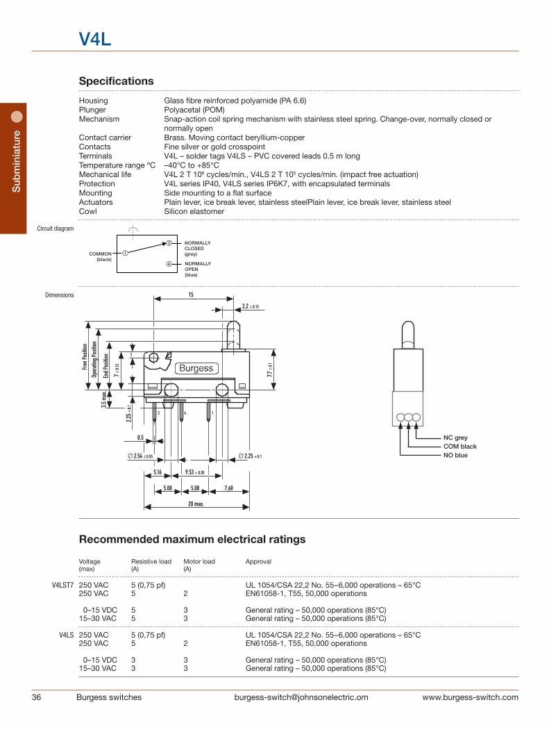
Housing Glass fibre reinforced polyamide (PA 6.6) Plunger Polyacetal (POM) Mechanism Snap-action coil spring mechanism with stainless steel spring. Change-over, normally closed or
normally open Contact carrier Brass. Moving contact beryllium-copper Contacts Fine silver or gold crosspoint Terminals V4L – solder tags V4LS – PVC covered leads 0.5 m long Temperature range ºC –40°C to +85°C Mechanical life V4L 2 T 106 cycles/min., V4LS 2 T 105 cycles/min. (impact free actuation) Protection V4L series IP40, V4LS series IP6K7, with encapsulated terminals Mounting Side mounting to a flat surface Actuators Plain lever, ice break lever, stainless steelPlain lever, ice break lever, stainless steel Cowl Silicon elastomer
Circuit diagram
Dimensions
COMMON(black)
NORMALLYCLOSED(grey)
NORMALLYOPEN(blue)
Recommended maximum electrical ratings
Voltage Resistive load Motor load Approval (max) (A) (A)
V4LST7 250 VAC 5 (0,75 pf) UL 1054/CSA 22,2 No. 55–6,000 operations – 65°C 250 VAC 5 2 EN61058-1, T55, 50,000 operations 0–15 VDC 5 3 General rating – 50,000 operations (85°C) 15–30 VAC 5 3 General rating – 50,000 operations (85°C)
V4LS 250 VAC 5 (0,75 pf) UL 1054/CSA 22,2 No. 55–6,000 operations – 65°C 250 VAC 5 2 EN61058-1, T55, 50,000 operations
0–15 VDC 3 3 General rating – 50,000 operations (85°C) 15–30 VAC 3 3 General rating – 50,000 operations (85°C)
NC greyCOM blackNO blue

37Burgess switches [email protected]
Sub
miniature
V4L
Ordering Reference Actuating Release Free Operating Movement Total overtravel Overtravel Actuator Reference Force Force Position Position Differential Position Maximum Minimum Maximum Maximum Minimum Minimum (N) (ozf) (N) (ozf) (mm) (in) (mm) (in) (mm) (in) (mm) (in) (mm) (in)
Plunger V4LT7 2,4 8,60 0,4 1,44 12,9 0,507 11,7 ± 0.4 0,46 ± 0.012 0,9 0,023 9,2 0,36 2,2 0,09 V4LST7 2,5 9,00 0,5 1,78 12,9 0,507 11,7 ± 0.4 0,46 ± 0.012 0,9 0,023 9,2 0,36 2,2 0,09 A1 Lever V4L… 2,4 8,60 0,4 1,44 14,5 0,57 12,6 ± 0,8 0,59 ± 0.03 1,0 0,04 9,6 0,38 2,2 0,09 V4LS… 2,5 9,00 0,5 1,78 14,5 0,57 12,6 ± 0,8 0,59 ± 0.03 1,0 0,04 9,6 0,38 2,2 0,09
Width of lever 4.0 mm/0.16 in
A2 Lever V4L… 1,5 5,70 0,3 1,08 16,5 0,65 13,5 ± 1.0 0,53 ± 0.04 1,3 0,05 9,6 0,38 2,9 1,1 V4LS… 2 7,20 0,3 1,08 16,5 0,65 13,5 ± 1.0 0,53 ± 0.04 1,3 0,05 9,6 0,38 2,9 1,1
Width of lever 4.0 mm/0.16 in
F Lever V4L… For positions and forces of this actuator please contact Burgess V4LS…
Width of lever 4.0 mm/0.16 in

38 Burgess switches [email protected]
Sub
min
iatu
re
V4L
Basic type V4L
Type of sealing No symbol, unsealed S Sealed IP6K7 Terminals No symbol, pre-wired 500 mm with cable FLRY 0.5 mm2 and cable box (V4LS only) T7 Solder 2.95 T 0.5 T 3.55 long Circuit No symbol, change over
Actuators No symbol, without lever A1 Plain lever 20.0 mm, fitted at the end opposite to plunger A2 Plain lever 30.0 mm, fitted at the end opposite to plunger F Special lever F type 20.0 mm, fitted at the end opposite to plunger
Contact Material No symbol, Ag X Gold alloy on silver palladium crosspoint (AUX)
Other contact materials on special request Approvals No symbol, without approval UL UL and CSA approval EN ENEC approval only UN UL, CSA and ENEC approval
Special Features /□□□□ Burgess specialise in customer specific solutions. Additional product variants are available or can be provided. If your requirements cannot be satisfied from the options listed, please contact us.
Ordering Reference Example: V4L S T7 A1 X UL

Burgess switches [email protected]
Locknut mounting
Sealed Microswitch
Circuit diagram
Dimensions
NORMALLY OPEN (blue)
COMMON(black)
NORMALLY CLOSED (grey)
1
4
2
33
4,8
2,37
13,02
5,66
3,10
2,80
22,22 ± 0,13,10
2,8
3,50
10,2
9 ±
0,1
13,1
MAX
OPE
RAT
ING
POSN
FREE
PO
SITI
ON
10,4
MAX
40 Burgess switches [email protected]
Min
iatu
re s
eale
dM
iniature sealed
V3NS
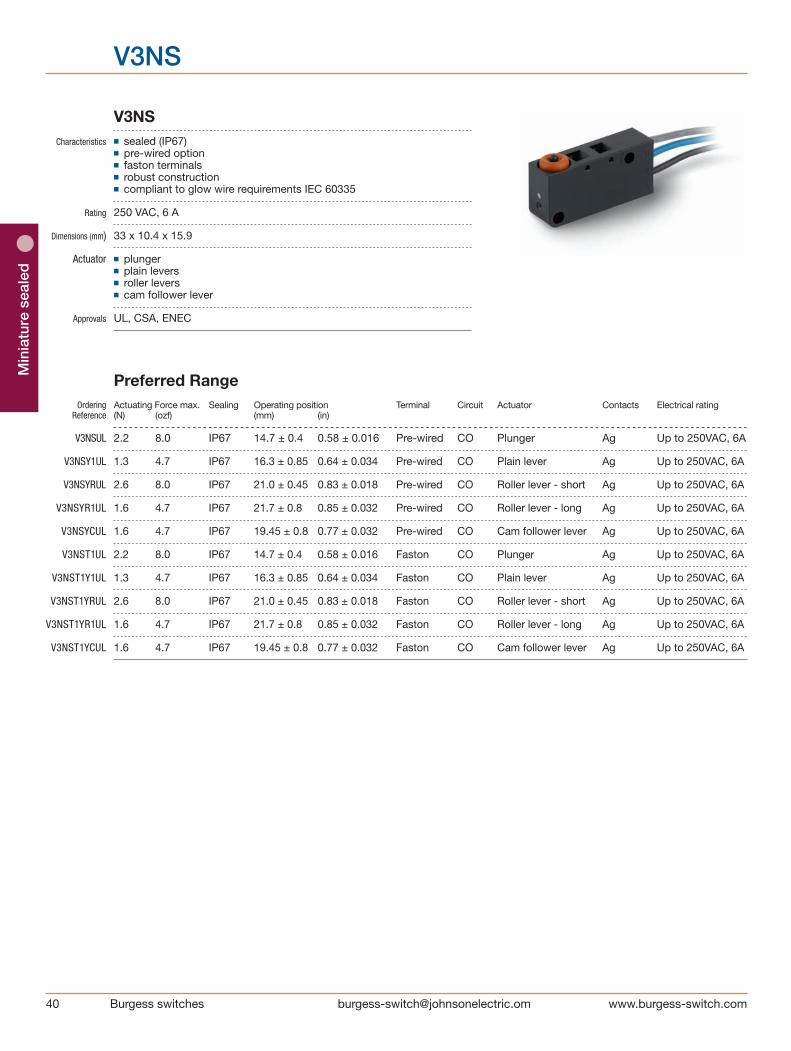
V3NS Characteristics ■ sealed (IP67) ■ pre-wired option ■ faston terminals ■ robust construction ■ compliant to glow wire requirements IEC 60335
Rating 250 VAC, 6 A
Dimensions (mm) 33 x 10.4 x 15.9
Actuator ■ plunger ■ plain levers ■ roller levers ■ cam follower lever
Approvals UL, CSA, ENEC
Preferred Range Ordering Actuating Force max. Sealing Operating position Terminal Circuit Actuator Contacts Electrical rating Reference (N) (ozf) (mm) (in)
V3NSUL 2.2 8.0 IP67 14.7 ± 0.4 0.58 ± 0.016 Pre-wired CO Plunger Ag Up to 250VAC, 6A
V3NSY1UL 1.3 4.7 IP67 16.3 ± 0.85 0.64 ± 0.034 Pre-wired CO Plain lever Ag Up to 250VAC, 6A
V3NSYRUL 2.6 8.0 IP67 21.0 ± 0.45 0.83 ± 0.018 Pre-wired CO Roller lever - short Ag Up to 250VAC, 6A
V3NSYR1UL 1.6 4.7 IP67 21.7 ± 0.8 0.85 ± 0.032 Pre-wired CO Roller lever - long Ag Up to 250VAC, 6A
V3NSYCUL 1.6 4.7 IP67 19.45 ± 0.8 0.77 ± 0.032 Pre-wired CO Cam follower lever Ag Up to 250VAC, 6A
V3NST1UL 2.2 8.0 IP67 14.7 ± 0.4 0.58 ± 0.016 Faston CO Plunger Ag Up to 250VAC, 6A
V3NST1Y1UL 1.3 4.7 IP67 16.3 ± 0.85 0.64 ± 0.034 Faston CO Plain lever Ag Up to 250VAC, 6A
V3NST1YRUL 2.6 8.0 IP67 21.0 ± 0.45 0.83 ± 0.018 Faston CO Roller lever - short Ag Up to 250VAC, 6A
V3NST1YR1UL 1.6 4.7 IP67 21.7 ± 0.8 0.85 ± 0.032 Faston CO Roller lever - long Ag Up to 250VAC, 6A
V3NST1YCUL 1.6 4.7 IP67 19.45 ± 0.8 0.77 ± 0.032 Faston CO Cam follower lever Ag Up to 250VAC, 6A

Miniature sealed
Burgess switches
Miniature sealed
Specifications Housing Glass fibre reinforced flame retardant nylon Plunger Polyphenylene Sulphide Mechanism Snap-action, single pole Functions Change-over Cowl Silicone Rubber Contacts Silver Terminals Pre-wired, Faston Temperature Range -40°C to +85°C Mechanical Life 1 million cycles minimum (impact free operation) Protection IP67 (enclosure) Mounting Side mounting Actuators Plain lever, cam follower lever - stainless steel, roller levers - stainless steel, acetal roller
Circuit diagram
Dimensions
V3NS
Recommended maximum electrical ratings Voltage Load Approval (max) (A)
125 VAC 6 (0.75pf) UL 1054/CSA 22.2 No.55 - 6000 operations (85°C) 250 VAC 6 (0.75pf) UL 1054/CSA 22.2 No.55 - 6000 operations (85°C) 250 VAC 6 (2) EN61058-1, T85 50,000 operations 250 VAC 4 General inductive rating - 200,000 operations minimum 250 VAC 5 General resistive rating - 200,000 operations minimum 30 vdc 5 General resistive rating - 200,000 operations minimum 5 vdc 0.001 General resistive rating - 1 million operations minimum
COMMON(black)
NORMALLY CLOSED (grey)
NORMALLY OPEN (blue)
1
4
2
6.4 x 0.8 FASTON (T1)
4.8 x 0.5 FASTON (T3)300 MIN3.
10
4.8
33
10.4
MAX
2.37
20.23
13.02
5.66
2.8
13.1
MAX
OPER
ATIN
G PO
SN
FREE
POS
ITION
3.50
3.10
2.80
22.22 ±0.1
10.2
9±0
.1
11.5 MAX
6.4
0.8
5
5
4.8
9.1MAX
0.5 5
5
42 Burgess switches [email protected]
Min
iatu
re s
eale
d
V3NS
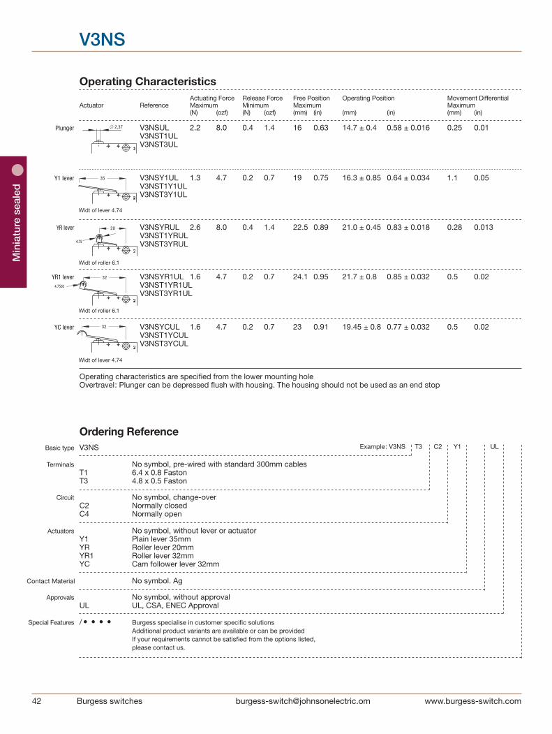
OperatingCharacteristics ActuatingForce ReleaseForce FreePosition OperatingPosition MovementDifferential Actuator Reference Maximum Minimum Maximum Maximum (N) (ozf) (N) (ozf) (mm) (in) (mm) (in) (mm) (in) Plunger V3NSUL 2.2 8.0 0.4 1.4 16 0.63 14.7±0.4 0.58±0.016 0.25 0.01 V3NST1UL V3NST3UL
Y1lever V3NSY1UL 1.3 4.7 0.2 0.7 19 0.75 16.3±0.85 0.64±0.034 1.1 0.05 V3NST1Y1UL V3NST3Y1UL
YRlever V3NSYRUL 2.6 8.0 0.4 1.4 22.5 0.89 21.0±0.45 0.83±0.018 0.28 0.013 V3NST1YRUL V3NST3YRUL
YR1lever V3NSYR1UL 1.6 4.7 0.2 0.7 24.1 0.95 21.7±0.8 0.85±0.032 0.5 0.02 V3NST1YR1UL V3NST3YR1UL
YClever V3NSYCUL 1.6 4.7 0.2 0.7 23 0.91 19.45±0.8 0.77±0.032 0.5 0.02 V3NST1YCUL V3NST3YCUL
Operatingcharacteristicsarespecifiedfromthelowermountinghole Overtravel:Plungercanbedepressedflushwithhousing.Thehousingshouldnotbeusedasanendstop
Basic type V3NS
Terminals No symbol, pre-wired with standard 300mm cables T1 6.4 x 0.8 Faston T3 4.8 x 0.5 Faston
Circuit No symbol, change-over C2 Normally closed C4 Normally open
Actuators No symbol, without lever or actuator Y1 Plain lever 35mm YR Roller lever 20mm YR1 Roller lever 32mm YC Cam follower lever 32mm
Contact Material No symbol. Ag
Approvals No symbol, without approval UL UL, CSA, ENEC Approval
Special Features /• • • • Burgess specialise in customer specific solutions Additional product variants are available or can be provided If your requirements cannot be satisfied from the options listed, please contact us.
Ordering Reference Example: V3NS T3 C2 Y1 UL
Widt of lever 4.74
Widt of lever 4.74
Widt of roller 6.1
Widt of roller 6.1
4.75
4.7500
∅ 2,37
35
20
32
32
Miniature sealed
Burgess switches
V3S
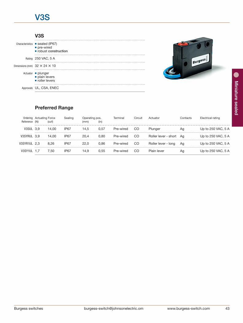
V3S Characteristics ■ sealed (IP67) ■ pre-wired ■ robust construction
Rating 250 VAC, 5 A Dimensions (mm) 32 • 24 • 10
Actuator ■ plunger ■ plain levers ■ roller levers
Approvals UL, CSA, ENEC
Preferred Range
Ordering Actuating Force Sealing Operating pos. Terminal Circuit Actuator Contacts Electrical rating Reference (N) (ozf) (mm) (in)
V3SUL 3,9 14,00 IP67 14,5 0,57 Pre-wired CO Plunger Ag Up to 250 VAC, 5 A
V3SYRUL 3,9 14,00 IP67 20,4 0,80 Pre-wired CO Roller lever - short Ag Up to 250 VAC, 5 A
V3SYR1UL 2,3 8,26 IP67 22,0 0,86 Pre-wired CO Roller lever - long Ag Up to 250 VAC, 5 A
V3SY1UL 1,7 7,50 IP67 14,9 0,55 Pre-wired CO Plain lever Ag Up to 250 VAC, 5 A

44 Burgess switches [email protected]
Min
iatu
re s
eale
d
V3S
Specifications Housing Glass fibre reinforced flame retardent nylon Plunger Acetal (lever types), stainless steel (plunger types) Mechanism Snap-action, single pole Functions Change-over Cowl Silicone rubber Contacts Silver Terminals ºC Pre-wired Temperature range –40°C to +85°C Mechanical life 106 cycles minimum, impact-free actuation Protection IP67 (enclosure) Mounting Side mounting Actuators Plain lever - stainless steel, Roller levers - stainless steel, nylon roller
Circuit diagram
Dimensions
(BLACK)1
4
2
COMMON
OPEN (BLUE)NORMALLY
CLOSED (GREY)NORMALLY
V3S CIRCUIT DIAGRAM
BURGESS
[19.7]
500 MIN
+0.12
2 MOUNTING HOLESØ3.2 -0.00 [0.13]
BLACK
BLUE
POSIT
IONFR
EE [0.53
]
[0.41
]
[0.08]
[0.13][0.875]
[0.09]
[0.42
][0.
41]
3.3 MAX
22.23±0.05
2.0
10.7
5 M
AX10
.29±
0.05
FREE
PO
SITI
ON
13.4
M
AX
10.5
[0.41]
[0.09]
GREY
Ø2.4
10.5 MAX
31.7 MAX
V3SUL FULL SIZE
Recommended maximum electrical ratings
Voltage Load Approval (max) (A)
125 VAC 5 (0.75 pf) UL 1054/CSA 22.2 No. 55 - 6,000 operations (85°C) 250 VAC 5 (0.75 pf) UL 1054/CSA 22.2 No. 55 - 6,000 operations (85°C) 250 VAC 5 EN61058-1, T85, 10,000 operations 0 - 15 VDC 6 General rating - 50,000 operations (85°C) 15 - 30 VDC 3 General rating - 50,000 operations (85°C)

Miniature sealed
Burgess switches
V3S
Operating Characteristics Actuating Release Free Operating Movement Actuator Reference Force Force Position Position Differential Maximum Minimum Maximum Maximum (N) (ozf) (N) (ozf) (mm) (in) (mm) (in) (mm) (in)
Plunger V3SUL 3,90 14,0 1,10 4,00 15,9 0,63 14,5 ± 0.5 0,57 ± 0.02 0,4 0,016 Plain lever V3SY1UL 1,65 6,0 0,42 1,50 13,4 0,71 14,9 ± 1,0 0,59 ± 0.4 1,0 0,040 Roller lever - short V3SYRUL 3,90 14,0 1,10 4,00 22,1 0,87 20,45 ± 0.64 0,8 ± 0.025 0,40 0,016 Roller lever - long V3SYR1UL 1,65 7,5 0,42 1,50 18,1 0,71 14,9 ± 01.0 0,55 ± 0.039 1,00 0,040
Over travel: Plunger can be depressed flush with housing. The housing should not be used as an end stop.
Ø4.78 X 4.78[Ø0.19 X 0.19]
24.2 [0.95][0.46]
Ø4.78 X 4.78[Ø0.19 X 0.19]
11.7
26.2 [1.03]
Ø4.78 X 4.78[Ø0.19 X 0.19]
24.2 [0.95][0.46]
Ø4.78 X 4.78[Ø0.19 X 0.19]
11.7
26.2 [1.03]
Ø4.78 X 4.78[Ø0.19 X 0.19]
24.2 [0.95][0.46]
Ø4.78 X 4.78[Ø0.19 X 0.19]
11.7
26.2 [1.03]
Ø4.78 X 4.78[Ø0.19 X 0.19]
24.2 [0.95][0.46]
Ø4.78 X 4.78[Ø0.19 X 0.19]
11.7
26.2 [1.03]
Basic type V3S
Circuit No symbol, change-over
Actuators No symbol, without lever or actuator Y1 Plain lever 26.2 mm YR Roller lever 11.7 mm YR1 Roller lever 24.2 mm
Contact Material No symbol, Ag
Terminals No symbol, fitted with standard 500 mm cables
Approvals No symbol, without approval UL UL and CSA approval, ENEC
Special Features /□□□□ Burgess specialise in customer specific solutions. Additional product variants are available or can be provided. If your requirements cannot be satisfied from the options listed, please contact us.
Ordering Reference Example: V3S Y1 UL
Locknut mounting
Precision Switches
Circuit diagram
Dimensions
[email protected] switches
Stand
ard
3BR
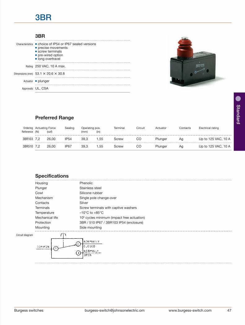
3BR Characteristics ■ choice of IP54 or IP67 sealed versions ■ precise movements ■ screw terminals ■ pre-wired option ■ long overtravel
Rating 250 VAC, 10 A max. Dimensions (mm) 53.1 • 20.6 • 30.8
Actuator ■ plunger
Approvals UL, CSA
Preferred Range
Ordering Actuating Force Sealing Operating pos. Terminal Circuit Actuator Contacts Electrical rating Reference (N) (ozf) (mm) (in)
3BR103 7,2 26,00 IP54 39,3 1,55 Screw CO Plunger Ag Up to 125 VAC, 10 A
3BR510 7,2 26,00 IP67 39,3 1,55 Screw CO Plunger Ag Up to 125 VAC, 10 A
Specifications Housing Phenolic Plunger Stainless steel Cowl Silicone rubber Mechanism Single pole change-over Contacts Silver Terminals Screw terminals with captive washers Temperature –10°C to +85°C Mechanical life 106 cycles minimum (impact free actuation) Protection 3BR / 510 IP67 / 3BR103 IP54 (enclosure) Mounting Side mounting
Circuit diagram

48 Burgess switches [email protected]
Sta
ndar
d
3BR
Dimensions
Recommended maximum electrical ratings
Voltage Load Horsepower Approval (max) (A)
250 VAC 5 (0.75 pf) - CSA 22.2 No. 55 - 6,000 operations 125 VAC 10 (0.75 pf) - CSA 22.2 No. 55 - 6,000 operations 250 VAC - 1⁄4 HP (0.45 pf) CSA 22.2 No. 55 - 6,000 operations 125 VAC - 1⁄8 HP (0.45 pf) CSA 22.2 No. 55 - 6,000 operations 0 - 15 VDC 10 - General rating - 50,000 operations 15 - 30 VDC 5 - General rating - 50,000 operations
Operating Characteristics Actuating Release Free Operating Movement Overtravel Actuator Reference Force Force Position Position Differential Maximum Minimum Maximum Maximum (N) (ozf) (N) (ozf) (mm) (in) (mm) (in) (mm) (in) (mm) (in)
Plunger 3BR103 7,2 26,00 1,7 6 40,8 1,6 39,3 ± 0.4 1,55 ± 0.016 0,08 0,003 4,6 0,18 3BR/510
Basic type 3BR
Environmental SH Sealed terminals with horizontal exiting 500 mm cables IP67 sealing 103 Sealed to IP54 510 Sealed to IP67
Special Features /□□□□ Burgess specialise in customer specific solutions. Additional product variants are available or can be provided. If your requirements cannot be satisfied from the options listed, please contact www.saia-burgess.com or your local SB outlet.
Ordering Reference Example: 3BR SH

Burgess switches [email protected]
Locknut mounting
Metal housed Switches
1
4
2
COMMON
OPENNORMALLY
CLOSEDNORMALLY
Circuit diagram
Dimensions
[0.3
4]
8.5
MA
X
+0.122 MOUNTING HOLES
Ø3.2-0.00 [0.13][0.16]
Ø3.97
POSI
TION
[0.24] [0.63]
[1.67]
[0.7
7]
[0.6
3]
[0.1
3]
[0.3
3]
[0.22]
[0.63]
OP
ER
ATI
NG
FRE
E P
OS
ITIO
N
19.6
0 M
AX
15.9 3.
18±
0.05
6.00 15.88±0.05
42.3 MAX
8.30
5.5
16.0 MAX
V9N 3/4 FULL SIZE
50 Burgess switches [email protected]
Met
al h
ous
ed
V9N
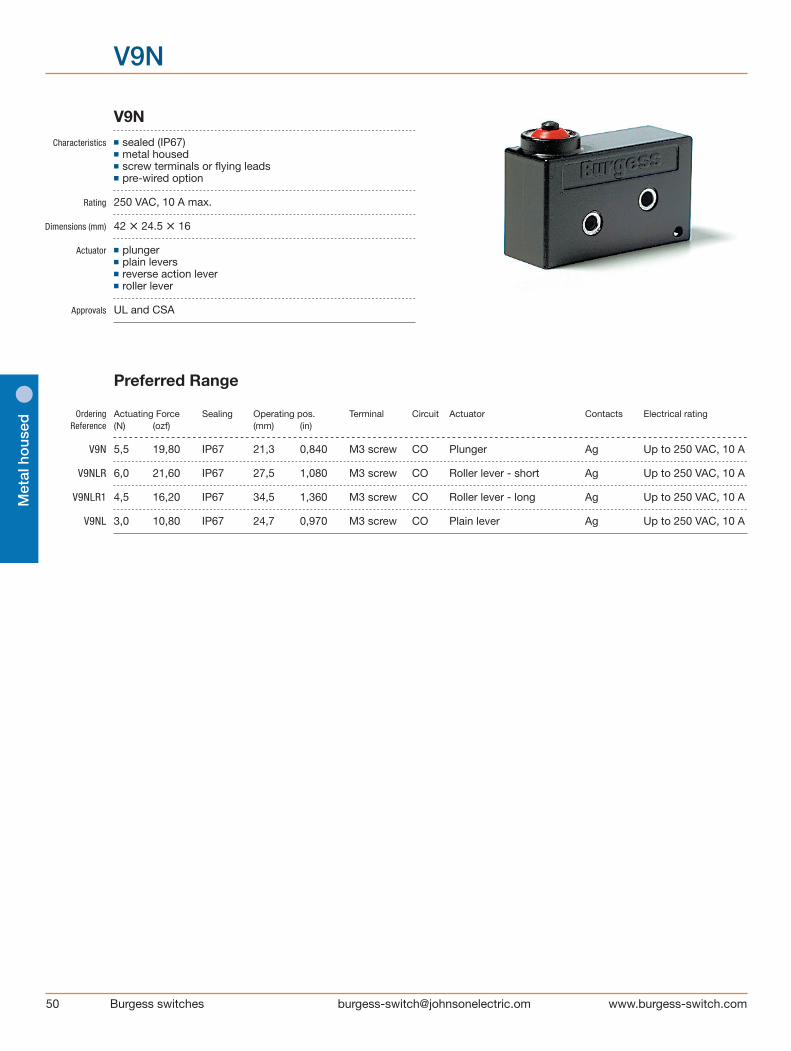
V9N Characteristics ■ sealed (IP67) ■ metal housed ■ screw terminals or flying leads ■ pre-wired option
Rating 250 VAC, 10 A max.
Dimensions (mm) 42 • 24.5 • 16
Actuator ■ plunger ■ plain levers ■ reverse action lever ■ roller lever
Approvals UL and CSA
Preferred Range
Ordering Actuating Force Sealing Operating pos. Terminal Circuit Actuator Contacts Electrical rating Reference (N) (ozf) (mm) (in)
V9N 5,5 19,80 IP67 21,3 0,840 M3 screw CO Plunger Ag Up to 250 VAC, 10 A
V9NLR 6,0 21,60 IP67 27,5 1,080 M3 screw CO Roller lever - short Ag Up to 250 VAC, 10 A
V9NLR1 4,5 16,20 IP67 34,5 1,360 M3 screw CO Roller lever - long Ag Up to 250 VAC, 10 A
V9NL 3,0 10,80 IP67 24,7 0,970 M3 screw CO Plain lever Ag Up to 250 VAC, 10 A

[email protected] switches
Metal ho
used
V9N
1
4
2
COMMON
OPENNORMALLY
CLOSEDNORMALLY
[0.3
4]
8.5
MA
X
+0.122 MOUNTING HOLES
Ø3.2-0.00 [0.13][0.16]
Ø3.97
POSI
TION
[0.24] [0.63]
[1.67]
[0.7
7]
[0.6
3]
[0.1
3]
[0.3
3]
[0.22]
[0.63]
OP
ER
ATI
NG
FRE
E P
OS
ITIO
N
19.6
0 M
AX
15.9 3.
18±
0.05
6.00 15.88±0.05
42.3 MAX
8.30
5.5
16.0 MAX
V9N 3/4 FULL SIZE
Specifications Housing Zinc diecasting Plunger Acetal Mechanism Snap-action, single pole Functions Change-over Cowl Silicon rubber Contacts Silver Terminals M3 screws with captive washers or pre-wired Temperature range –40°C to +125°C, switch only -10°C to +85°C pre-wired and roller levers Mechanical life 106 cycles minimum, impact-free actuation Protection IP67 (enclosure) Mounting Side mounting Actuators Plain levers - stainless steel, roller levers - stainless steel, nylon roller
Circuit diagram
Dimensions
Recommended maximum electrical ratings
Voltage Load Approval (max) (A)
250 VAC 10 (0.75 pf) UL 1054/CSA 22.2 No. 55 - 6,000 operations (85°C) 0 - 15 VDC 10 General rating - 50,000 operations (85°C) 15 - 30 VDC 10 General rating - 50,000 operations (85°C)

52 Burgess switches [email protected]
Met
al h
ous
ed
V9N
14.0
[0.55][Ø0.38 X 0.18]Ø9.5 X 4.6
[0.68]17.2
[1.75]44.5
Ø9.5 X 4.6
[1.0]
[Ø0.38 X 0.18]25.5
[1.13]28.70
[1.27]
32.3Ø9.5 X 4.6[Ø0.38 X 0.18]
[0.87]
22.2Ø4.8 X 4.8[Ø0.19 X 0.19]
Operating Characteristics Actuating Release Free Operating Movement Over Actuator Reference Force Force Position Position Differential travel Maximum Minimum Maximum Maximum (N) (ozf) (N) (ozf) (mm) (in) (mm) (in) (mm) (in) (mm) (in)
Plunger V9N 5,5 19,8 1,0 3,6 22,6 0,89 21,3 ± 0.3 0,84 ± 0.012 0,35 0,014 *
Roller V9NLR 6,0 21,6 1,3 4,7 31,0 1,22 27,5 ± 0.5 1,08 ± 0.02 0,35 0,014 * lever - short
Roller V9NLR1 4,5 16,2 0,8 2,9 39,0 1,54 34,5 ± 0.7 1,36 ± 0.028 0,60 0,024 * lever - long
Plain lever V9NL 3,0 10,8 0,6 2,1 31,0 1,22 24,7 ± 01.0 0,97 ± 0.039 0,70 0,028 *
Reverse action V9NM 7,5 27,0 1,5 5,4 26,0 1,02 22,4 ± 0.5 0,88 ± 0.02 0,50 0,020 3,50 0,137 lever - short
Reverse action V9NML 4,5 16,2 1,0 3,6 29,0 1,14 23,6 ± 01.0 0,93 ± 0.039 1,20 0,047 6,00 0,236 lever - long
Reverse action V9NMR 9,5 34,2 1,5 5,4 36,0 1,42 32,9 ± 0.5 1,295 ± 0.02 0,45 0,018 2,00 0,079 roller lever - short
Reverse action V9NMLR 5,0 18,0 1,0 3,6 39,5 1,56 34,0 ± 01.0 1,34 ± 0.039 1,00 0,039 5,50 0,216 roller lever - long
Operating characteristics are specified from lower mounting hole * Plunger can be depressed flush with housing. The housing should not be used as an end stop.
14.0
[0.55][Ø0.38 X 0.18]Ø9.5 X 4.6
[0.68]17.2
[1.75]44.5
Ø9.5 X 4.6
[1.0]
[Ø0.38 X 0.18]25.5
[1.13]28.70
[1.27]
32.3Ø9.5 X 4.6[Ø0.38 X 0.18]
[0.87]
22.2Ø4.8 X 4.8[Ø0.19 X 0.19]
14.0
[0.55][Ø0.38 X 0.18]Ø9.5 X 4.6
[0.68]17.2
[1.75]44.5
Ø9.5 X 4.6
[1.0]
[Ø0.38 X 0.18]25.5
[1.13]28.70
[1.27]
32.3Ø9.5 X 4.6[Ø0.38 X 0.18]
[0.87]
22.2Ø4.8 X 4.8[Ø0.19 X 0.19]
14.0
[0.55][Ø0.38 X 0.18]Ø9.5 X 4.6
[0.68]17.2
[1.75]44.5
Ø9.5 X 4.6
[1.0]
[Ø0.38 X 0.18]25.5
[1.13]28.70
[1.27]
32.3Ø9.5 X 4.6[Ø0.38 X 0.18]
[0.87]
22.2Ø4.8 X 4.8[Ø0.19 X 0.19]
14.0
[0.55][Ø0.38 X 0.18]Ø9.5 X 4.6
[0.68]17.2
[1.75]44.5
Ø9.5 X 4.6
[1.0]
[Ø0.38 X 0.18]25.5
[1.13]28.70
[1.27]
32.3Ø9.5 X 4.6[Ø0.38 X 0.18]
[0.87]
22.2Ø4.8 X 4.8[Ø0.19 X 0.19]
14.0
[0.55][Ø0.38 X 0.18]Ø9.5 X 4.6
[0.68]17.2
[1.75]44.5
Ø9.5 X 4.6
[1.0]
[Ø0.38 X 0.18]25.5
[1.13]28.70
[1.27]
32.3Ø9.5 X 4.6[Ø0.38 X 0.18]
[0.87]
22.2Ø4.8 X 4.8[Ø0.19 X 0.19]
14.0
[0.55][Ø0.38 X 0.18]Ø9.5 X 4.6
[0.68]17.2
[1.75]44.5
Ø9.5 X 4.6
[1.0]
[Ø0.38 X 0.18]25.5
[1.13]28.70
[1.27]
32.3Ø9.5 X 4.6[Ø0.38 X 0.18]
[0.87]
22.2Ø4.8 X 4.8[Ø0.19 X 0.19]
14.0
[0.55][Ø0.38 X 0.18]Ø9.5 X 4.6
[0.68]17.2
[1.75]44.5
Ø9.5 X 4.6
[1.0]
[Ø0.38 X 0.18]25.5
[1.13]28.70
[1.27]
32.3Ø9.5 X 4.6[Ø0.38 X 0.18]
[0.87]
22.2Ø4.8 X 4.8[Ø0.19 X 0.19]

[email protected] switches
Metal ho
used
V9N
Basic typ V9N
Actuators No symbol, without lever L Plain lever 44.5 mm LR Roller lever 22.2 mm LR1 Roller lever 32.3 mm M Reverse action lever 187.2 mm ML Reverse action lever 28.7 mm MR Reverse action roller lever 14.0 mm MLR Reverse action roller lever 25.5 mm
Terminals No symbol, unwired H Horizontal pre-wired cable V Vertical pre-wired cable
Pre-wired with No symbol, 1 m cable Terminals H + V
Special Features /□□□□ Burgess specialise in customer specific solutions. Additional product variants are available or can be provided. If your requirements cannot be satisfied from the options listed, please contact us.
Ordering Reference Example: V9N L H

54 Burgess switches [email protected]
Met
al h
ous
ed
4BR
4BR Characteristics ■ choice of IP54 or IP67 sealed versions ■ precise movements and exceptional repeat accuracy ■ robust metal housing ■ flying lead version available ■ long overtravel
Rating 125 VAC, 10 A max. Dimensions (mm) 53,1 • 20,6 • 29,2
Actuator ■ plunger
Approvals UL, CSA
Preferred Range
Ordering Actuating Force Sealing Operating pos. Terminal Circuit Actuator Contacts Electrical rating Reference (N) (ozf) (mm) (in)
4BR 7,2 26,00 IP54 39,3 1,550 Screw CO Plunger Ag Up to 125 VAC, 10 A
4BR510 7,2 26,00 IP67 39,3 1,550 Screw CO Plunger Ag Up to 125 VAC, 10 A
4BRSH 7.2 26,00 IP67 39,3 1,550 Pre-wired CO Plunger Ag Up to 125 VAC, 10 A

[email protected] switches
Metal ho
used
4BR
BURGESS
2
B
C
4
A1
[0.4
5]
[2.09]
[0.8
1][0
.7]
[1.0]
6BA TERMINAL SCREWSWITH CAPTIVE WASHERS
VIEW WITH COVER REMOVED
Ø3.66-0.00 [0.14]+0.05
2 MOUNTING HOLES
11.4
MA
X
53.1 MAX
20.6
MA
X
25.4±0.05
17.8
MA
XOP
ER
ATI
NG
P
OS
ITIO
N
FRE
E
PO
SIT
ION
[0.31]Ø8.0
Specifications Housing Zinc based alloy Base Plate Phenolic Plunger Stainless steel Cowl Silicon rubber Mechanism Single pole change-over Contacts Silver Terminals Removable screw terminals, insulated cover plate Temperature –10°C to +85°C Mechanical life 106 cycles minimum (impact free actuation) Protection 4BR/510 IP67 / 4BR IP54 (enclosure) Mounting Side mounting
Circuit diagram
Dimensions
1A
4C
2B
COMMON
OPENNORMALLY
CLOSEDNORMALLY
Recommended maximum electrical ratings
Voltage Resistive load Inductive load Horsepower Approval (max) (A)
250 VAC 5 (0.75 pf) 5 - CSA 22.2 No. 55 - 6,000 operations 125 VAC 10 (0.75 pf) - - CSA 22.2 No. 55 - 6,000 operations 250 VAC - - 1⁄4 HP (0.45 pf) CSA 22.2 No. 55 - 6,000 operations 125 VAC - - 1⁄8 HP (0.45 pf) CSA 22.2 No. 55 - 6,000 operations 0 - 15 VDC 10 - - General rating - 50,000 operations 15 - 30 VDC 5 - - General rating - 50,000 operations
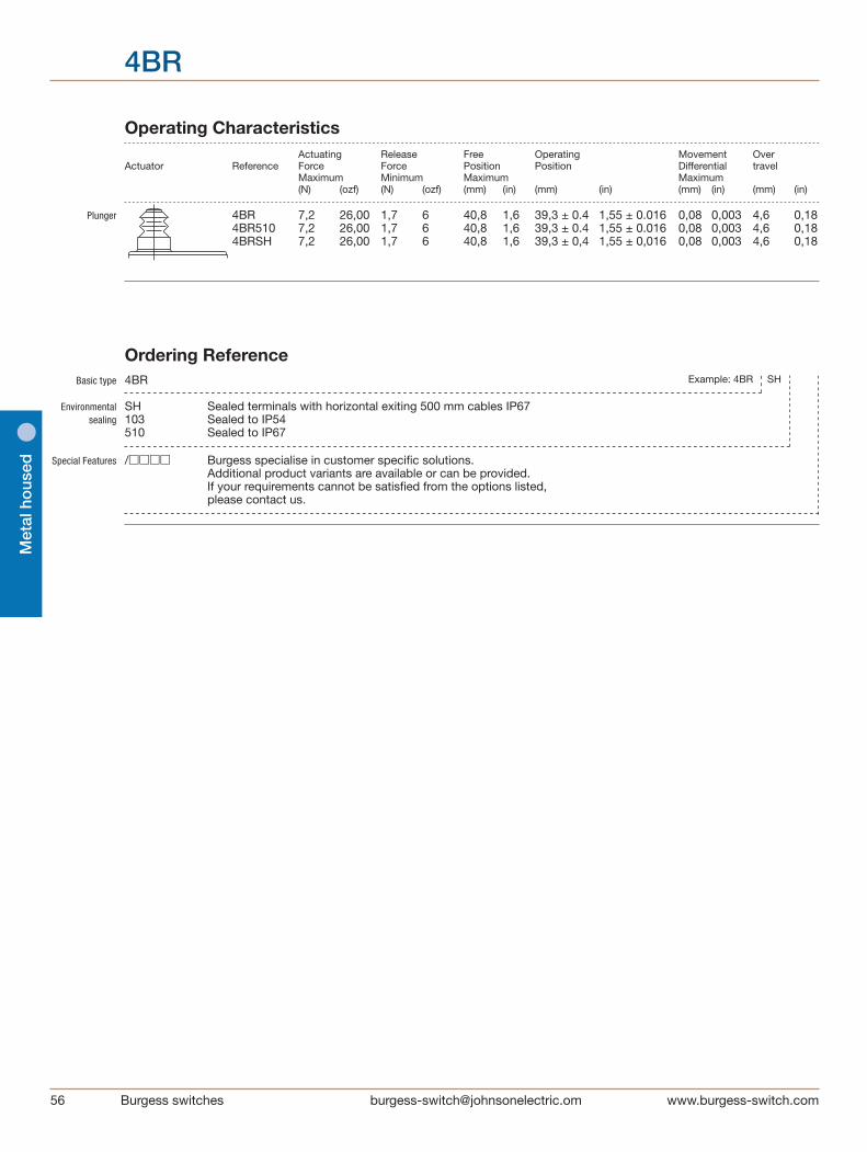
56 Burgess switches [email protected]
Met
al h
ous
ed
4BR
Operating Characteristics Actuating Release Free Operating Movement Over Actuator Reference Force Force Position Position Differential travel Maximum Minimum Maximum Maximum (N) (ozf) (N) (ozf) (mm) (in) (mm) (in) (mm) (in) (mm) (in)
Plunger 4BR 7,2 26,00 1,7 6 40,8 1,6 39,3 ± 0.4 1,55 ± 0.016 0,08 0,003 4,6 0,18 4BR510 7,2 26,00 1,7 6 40,8 1,6 39,3 ± 0.4 1,55 ± 0.016 0,08 0,003 4,6 0,18 4BRSH 7,2 26,00 1,7 6 40,8 1,6 39,3 ± 0,4 1,55 ± 0,016 0,08 0,003 4,6 0,18
4BR / 4BR/510
Basic type 4BR
Environmental SH Sealed terminals with horizontal exiting 500 mm cables IP67 sealing 103 Sealed to IP54 510 Sealed to IP67
Special Features /□□□□ Burgess specialise in customer specific solutions. Additional product variants are available or can be provided. If your requirements cannot be satisfied from the options listed, please contact us.
Ordering Reference Example: 4BR SH
Burgess switches [email protected]
Positive-action Switches
1
2
COMMON
CLOSEDNORMALLY
Dimensions
Locknut mounting
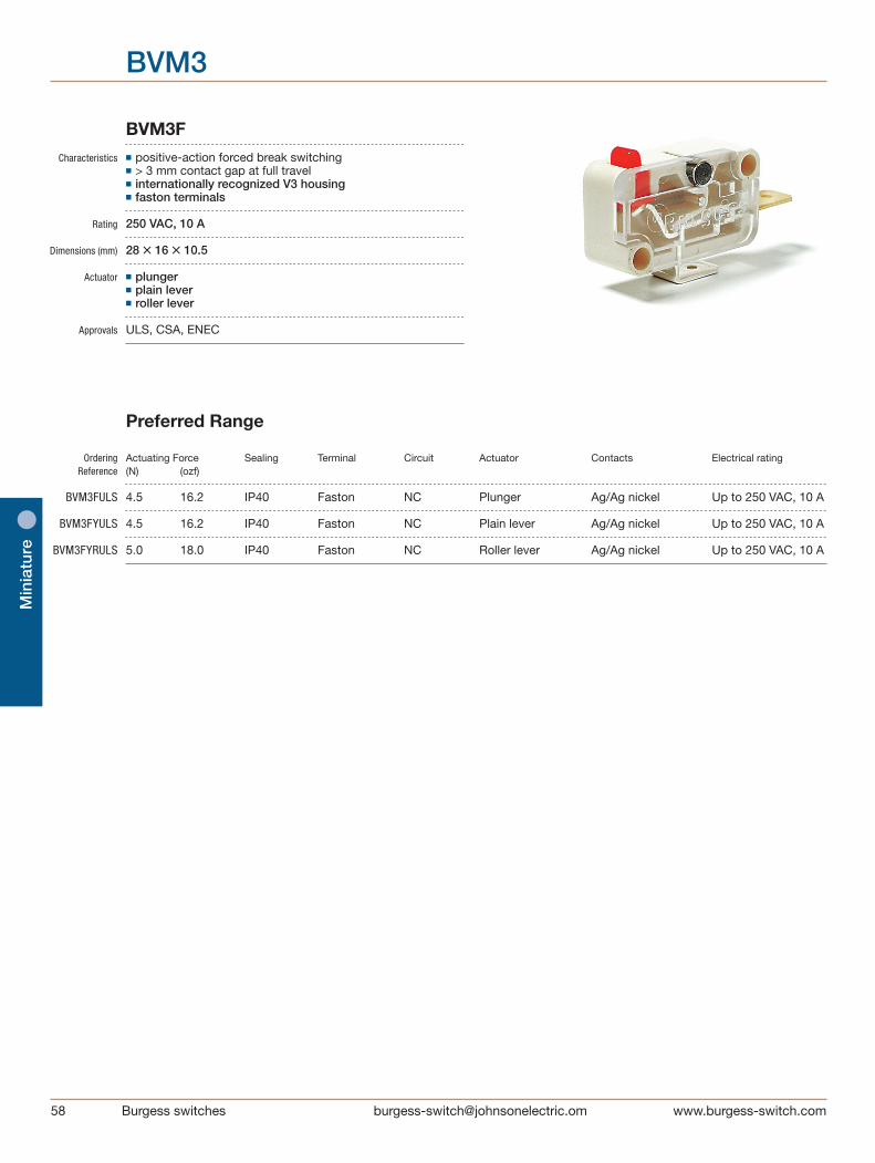
58 Burgess switches [email protected]
Min
iatu
re
BVM3
BVM3F Characteristics ■ positive-action forced break switching ■ > 3 mm contact gap at full travel ■ internationally recognized V3 housing ■ faston terminals
Rating 250 VAC, 10 A Dimensions (mm) 28 • 16 • 10.5
Actuator ■ plunger ■ plain lever ■ roller lever
Approvals ULS, CSA, ENEC
Preferred Range
Ordering Actuating Force Sealing Terminal Circuit Actuator Contacts Electrical rating Reference (N) (ozf)
BVM3FULS 4.5 16.2 IP40 Faston NC Plunger Ag/Ag nickel Up to 250 VAC, 10 A
BVM3FYULS 4.5 16.2 IP40 Faston NC Plain lever Ag/Ag nickel Up to 250 VAC, 10 A BVM3FYRULS 5.0 18.0 IP40 Faston NC Roller lever Ag/Ag nickel Up to 250 VAC, 10 A
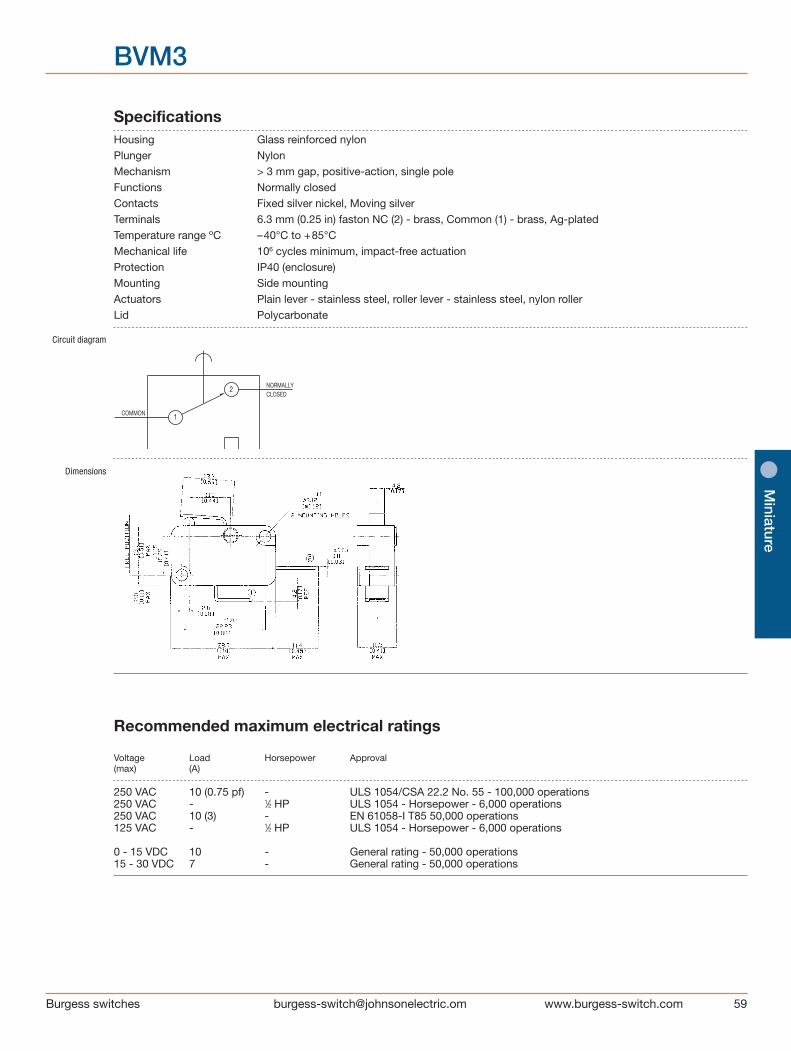
[email protected] switches
Miniature
BVM3
Specifications Housing Glass reinforced nylon Plunger Nylon Mechanism > 3 mm gap, positive-action, single pole Functions Normally closed Contacts Fixed silver nickel, Moving silver Terminals 6.3 mm (0.25 in) faston NC (2) - brass, Common (1) - brass, Ag-plated Temperature range ºC –40°C to +85°C Mechanical life 106 cycles minimum, impact-free actuation Protection IP40 (enclosure) Mounting Side mounting Actuators Plain lever - stainless steel, roller lever - stainless steel, nylon roller Lid Polycarbonate
Circuit diagram
Dimensions
1
2
COMMON
CLOSEDNORMALLY
Recommended maximum electrical ratings
Voltage Load Horsepower Approval (max) (A)
250 VAC 10 (0.75 pf) - ULS 1054/CSA 22.2 No. 55 - 100,000 operations 250 VAC - 1⁄2 HP ULS 1054 - Horsepower - 6,000 operations 250 VAC 10 (3) - EN 61058-I T85 50,000 operations 125 VAC - 1⁄2 HP ULS 1054 - Horsepower - 6,000 operations 0 - 15 VDC 10 - General rating - 50,000 operations 15 - 30 VDC 7 - General rating - 50,000 operations

60 Burgess switches [email protected]
Min
iatu
re
BVM3
Operating Characteristics Actuating Actuating Free Contact gap at Actuator Reference Force Force Position total travel at contact break at total travel Maximum Minimum Maximum Minimum (N) (ozf) (N) (ozf) (mm) (in) (mm) (in)
Plunger BVM3FULS 4,5 16,2 4,8 17,3 15,8 0,62 3,0 0,12
Y Lever BVM3FYULS 4,5 16,2 4,8 17,3 16,8 0,66 3,0 0,12
YR Lever BVM3FYRULS 5,0 18,0 5,5 19,8 22,35 0,88 3,0 0,12 Operating characteristics are specified from the mounting holes.
Total travel: Plunger can be depressed flush with housing. The housing should not be used as an end stop.
Ø 4.8 X 4.8[Ø 0.19 X 0.19] [0.46]
11.7
13.7[0.54]
Ø 4.8 X 4.8[Ø 0.19 X 0.19] [0.46]
11.7
13.7[0.54]
Ø 4.8 X 4.8[Ø 0.19 X 0.19] [0.46]
11.7
13.7[0.54]
Basic type BVM3
Terminals F Faston 6.3 • 0.8 mm
Actuators No symbol, without lever Y Straight lever 13.7 mm YR Roller lever 11.7 mm Approvals ULS UL 100 k operations and CSA approval, ENEC
Special Features /□□□□ Burgess specialise in customer specific solutions. Additional product variants are available or can be provided. If your requirements cannot be satisfied from the options listed, please contact us.
Ordering Reference Example: BVM3 F Y ULS
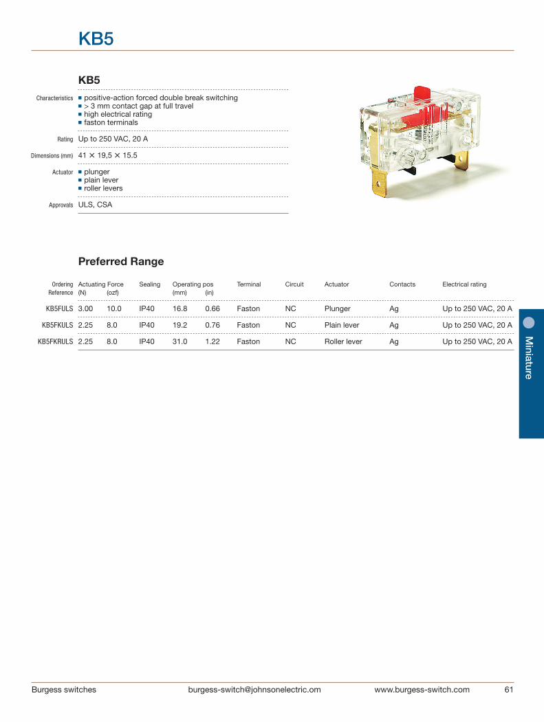
[email protected] switches
Miniature
KB5
KB5 Characteristics ■ positive-action forced double break switching ■ > 3 mm contact gap at full travel ■ high electrical rating ■ faston terminals
Rating Up to 250 VAC, 20 A
Dimensions (mm) 41 • 19,5 • 15.5
Actuator ■ plunger ■ plain lever ■ roller levers
Approvals ULS, CSA
Preferred Range
Ordering Actuating Force Sealing Operating pos Terminal Circuit Actuator Contacts Electrical rating Reference (N) (ozf) (mm) (in)
KB5FULS 3.00 10.0 IP40 16.8 0.66 Faston NC Plunger Ag Up to 250 VAC, 20 A
KB5FKULS 2.25 8.0 IP40 19.2 0.76 Faston NC Plain lever Ag Up to 250 VAC, 20 A
KB5FKRULS 2.25 8.0 IP40 31.0 1.22 Faston NC Roller lever Ag Up to 250 VAC, 20 A
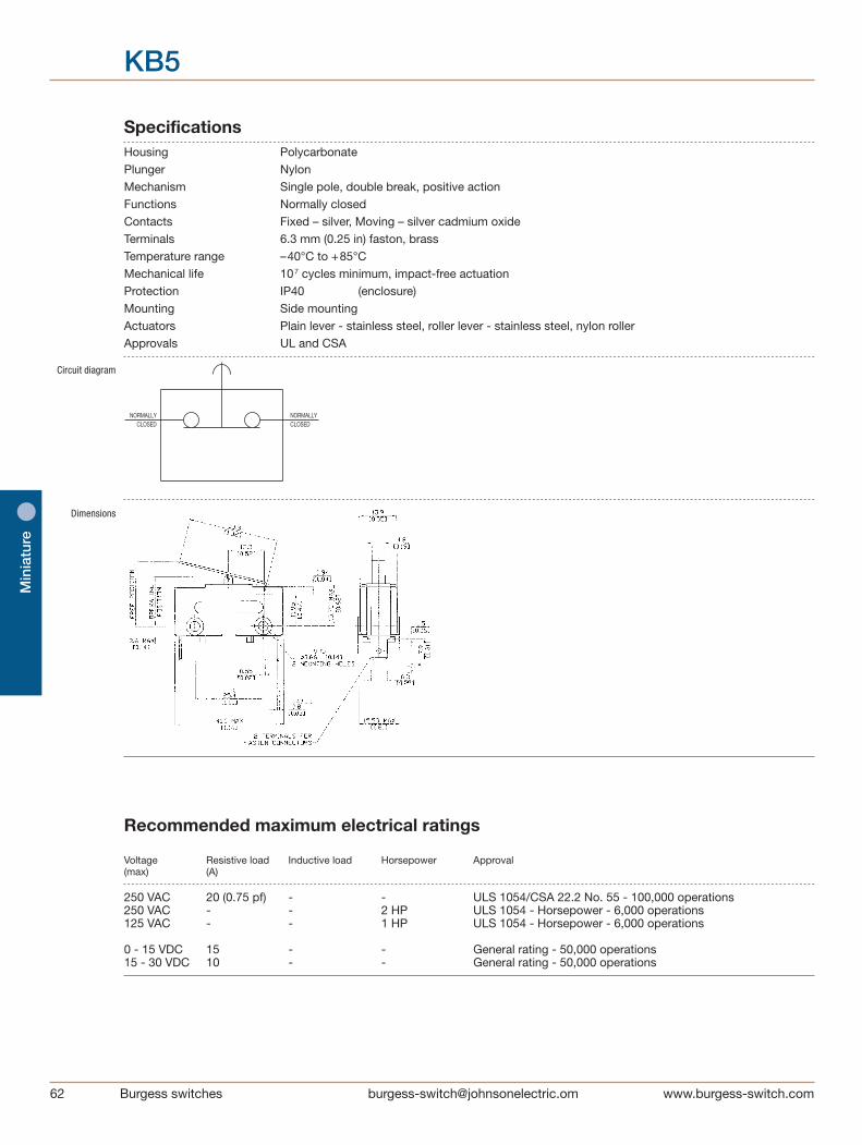
62 Burgess switches [email protected]
Min
iatu
re
KB5
Specifications Housing Polycarbonate Plunger Nylon Mechanism Single pole, double break, positive action Functions Normally closed Contacts Fixed – silver, Moving – silver cadmium oxide Terminals 6.3 mm (0.25 in) faston, brass Temperature range –40°C to +85°C Mechanical life 107 cycles minimum, impact-free actuation Protection IP40 (enclosure) Mounting Side mounting Actuators Plain lever - stainless steel, roller lever - stainless steel, nylon roller Approvals UL and CSA
Circuit diagram
Dimensions
NORMALLYCLOSED CLOSED
NORMALLY
Recommended maximum electrical ratings
Voltage Resistive load Inductive load Horsepower Approval (max) (A)
250 VAC 20 (0.75 pf) - - ULS 1054/CSA 22.2 No. 55 - 100,000 operations 250 VAC - - 2 HP ULS 1054 - Horsepower - 6,000 operations 125 VAC - - 1 HP ULS 1054 - Horsepower - 6,000 operations 0 - 15 VDC 15 - - General rating - 50,000 operations 15 - 30 VDC 10 - - General rating - 50,000 operations
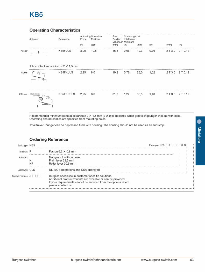
[email protected] switches
Miniature
Operating Characteristics Actuating Operation Free Contact gap at Actuator Reference Force Position Position total travel Maximum Minimum (N) (ozf) (mm) (in) (mm) (in) (mm) (in)
Plunger KB5FULS 3,00 10,8 16,8 0,66 19,3 0,76 2 T 3.0 2 T 0.12 1 At contact separation of 2 • 1,5 mm
K Lever KB5FKULS 2,25 8,0 19,2 0,76 26,0 1,02 2 T 3.0 2 T 0.12
KR Lever KB5FKRULS 2,25 8,0 31,0 1,22 36,5 1,40 2 T 3.0 2 T 0.12
Recommended minimum contact separation 2 • 1,5 mm (2 • 0,6) indicated when groove in plunger lines up with case. Operating characteristics are specified from mounting holes.
Total travel: Plunger can be depressed flush with housing. The housing should not be used as an end stop.
ROLLER Ø9.5 X 4.6[Ø0.37 X 0.18]
[1.2]
30.5[1.32]
33.5
ROLLER Ø9.5 X 4.6[Ø0.37 X 0.18]
[1.2]
30.5[1.32]
33.5
ROLLER Ø9.5 X 4.6[Ø0.37 X 0.18]
[1.2]
30.5[1.32]
33.5
Basic type KB5
Terminals F Faston 6.3 • 0.8 mm
Actuators No symbol, without lever K Plain lever 33.5 mm KR Roller lever 30.5 mm
Approvals ULS UL 100 k operations and CSA approved Special Features /□□□□ Burgess specialise in customer specific solutions. Additional product variants are available or can be provided. If your requirements cannot be satisfied from the options listed, please contact us.
Ordering Reference Example: KB5 F K ULS
KB5
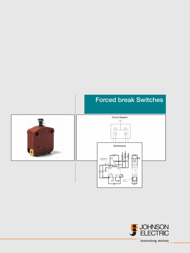
Forced break Switches
Circuit diagram
NORMALLY CLOSED
NORMALLY OPEN
2
43
1
Dimensions
2431243124312431
24312431
2431
[0.31]
[0.51]ɔ8.0
13.0±0.2
[0.39]
10.0[0.25 X 0.03]6.3 X 0.8
[0.2
7]
[0.47]12.0
22.0±0.1
[0.87]
É”4.3Å}0.05 [0.17]2 MOUNTING HOLES
[0.24]6.0
[1.18]
30.0
[1.2
5]
[1.1
9]
31.7
30.3 6.
0[0
.24]
TOTA
L TR
AV
EL
PO
SIT
ION
OP
ER
ATI
NG
P
OS
ITIO
NFR
EE
P
OS
ITIO
N
6.8
[0.16]
[0.51]ɔ4.0
13.0±0.2
[0.39]
10.0[0.25 X 0.03]6.3 X 0.8
[0.2
7]
[0.47]12.0
R2.5[0.1]
22.0±0.1
[0.87]
É”4.3Å}0.05 [0.17]2 MOUNTING HOLES
[0.24]6.0
[1.18]
30.0
[1.2
5]
[1.1
9]
31.7
30.3 6.
0[0
.24]
TOTA
L TR
AV
EL
PO
SIT
ION
OP
ER
ATI
NG
P
OS
ITIO
NFR
EE
P
OS
ITIO
N
6.8
[0.31]
[0.51]ɔ8.0
13.0±0.2
[0.39]
10.0[0.25 X 0.03]6.3 X 0.8
[0.2
7]
[0.47]12.0
22.0±0.1
[0.87]
É”4.3Å}0.05 [0.17]2 MOUNTING HOLES
[0.24]6.0
[1.18]
30.0
[1.2
6]
[1.1
9]
32.0
30.3 6.
0[0
.24]
TOTA
L TR
AV
EL
PO
SIT
ION
OP
ER
ATI
NG
P
OS
ITIO
NFR
EE
P
OS
ITIO
N
6.8
[0.16]
[0.51]ɔ4.0
13.0±0.2
[0.39]
10.0[0.25 X 0.03]6.3 X 0.8
[0.2
7]
[0.47]12.0
R2.5[0.1]
22.0±0.1
[0.87]
É”4.3Å}0.05 [0.17]2 MOUNTING HOLES
[0.24]6.0
[1.18]
30.0
[1.2
6]
[1.1
9]
32.0
30.3 6.
0[0
.24]
TOTA
L TR
AV
EL
PO
SIT
ION
OP
ER
ATI
NG
P
OS
ITIO
NFR
EE
P
OS
ITIO
N
6.8
[0.24]
[0.51]ɔ6.0
13.0±0.2
[0.39]10.0
[0.25 X 0.03]6.3 X 0.8
[0.2
7]
[0.47]12.0
22.0±0.1
[0.87]
É”4.3Å}0.05 [0.17]2 MOUNTING HOLES
[0.24]6.0
[1.18]
30.0
[1.2
6]
[1.1
9]
32.0
30.3 6.
0[0
.24]
TOTA
L TR
AV
EL
PO
SIT
ION
OP
ER
ATI
NG
P
OS
ITIO
NFR
EE
P
OS
ITIO
N
6.8
[0.31]
[0.51]ɔ8.0
13.0±0.2
[0.39]10.0
[0.25 X 0.03]6.3 X 0.8
[0.2
7]
[0.47]12.0
22.0±0.1
[0.87]
É”4.3Å}0.05 [0.17]2 MOUNTING HOLES
[0.24]6.0
[1.18]
30.0
[1.2
6]
[1.1
9]
32.0
30.3 6.
0[0
.24]
TOTA
L TR
AV
EL
PO
SIT
ION
OP
ER
ATI
NG
P
OS
ITIO
NFR
EE
P
OS
ITIO
N
6.8
[0.16]
[0.51]ɔ4.0
13.0±0.2
[0.39]10.0
[0.25 X 0.03]6.3 X 0.8
[0.2
7]
[0.47]12.0
R2.5[0.1]
22.0±0.1
[0.87]
É”4.3Å}0.05 [0.17]2 MOUNTING HOLES
[0.24]6.0
[1.18]
30.0
[1.2
6]
[1.1
9]
32.0
30.3 6.
0[0
.24]
TOTA
L TR
AV
EL
PO
SIT
ION
OP
ER
ATI
NG
P
OS
ITIO
N
FRE
E
PO
SIT
ION
6.8
XP RANGE
XP52E1Z11 3/4 FULL SIZEXP52Z11 3/4 FULL SIZEXP42E1Z11 3/4 FULL SIZEXP42Z11 3/4 FULL SIZE
XP2E2Z11 3/4 FULL SIZEXP2E1Z11 3/4 FULL SIZEXP2Z11 3/4 FULL SIZE

[email protected] switches
Forced
break
XP Characteristics ■ forced double break switching ■ positive-action force break option ■ > 3 mm contact gap at full travel option ■ faston terminals
Rating 400 VAC, 16 A
Dimensions (mm) 30 • 32 • 12
Actuator ■ plain plunger ■ mushroom plunger ■ plunger with external spring (for increased reset security) Approvals ENEC, UL, CSA
Preferred Range
Ordering Actuating Force Operating pos. Terminal Circuit Actuator Contacts Electrical rating Reference (N) (ozf) (mm) (in)
XP2Z11 3,0 10,0 14,9 0,587 Faston CO Straight plunger Ag nickel Up to 400 VAC, 16 A
XP42Z11 1,8 6,2 14,9 0,587 Faston NC Straight plunger Ag nickel Up to 400 VAC, 16 A
XP52Z11 3,0 10,0 13,0 0,511 Faston NO Straight plunger Ag nickel Up to 400 VAC, 16 A
XP52E1Z11 6,5 23,3 13,0 0,511 Faston NO Mushroom plunger, reset Ag nickel Up to 400 VAC, 16 A
XP2E2Z11 3,0 10,0 14,9 0,587 Faston CO Mushroom plunger, reset Ag nickel Up to 400 VAC, 16 A
XP
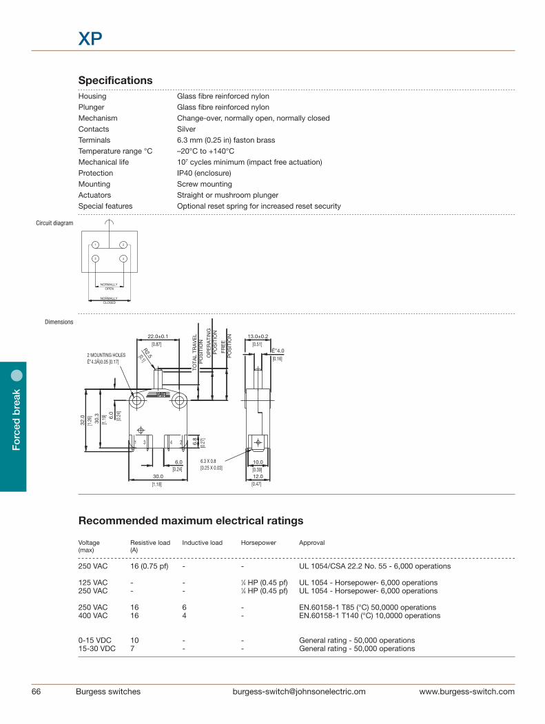
66 Burgess switches [email protected]
Fo
rced
bre
ak
XP
Specifications Housing Glass fibre reinforced nylon Plunger Glass fibre reinforced nylon Mechanism Change-over, normally open, normally closed Contacts Silver Terminals 6.3 mm (0.25 in) faston brass Temperature range °C –20°C to +140°C Mechanical life 107 cycles minimum (impact free actuation) Protection IP40 (enclosure) Mounting Screw mounting Actuators Straight or mushroom plunger Special features Optional reset spring for increased reset security
Circuit diagram
Dimensions
2431243124312431
24312431
2431
[0.31]
[0.51]ɔ8.0
13.0±0.2
[0.39]
10.0[0.25 X 0.03]6.3 X 0.8
[0.2
7]
[0.47]12.0
22.0±0.1
[0.87]
É”4.3Å}0.05 [0.17]2 MOUNTING HOLES
[0.24]6.0
[1.18]
30.0
[1.2
5]
[1.1
9]
31.7
30.3 6.
0[0
.24]
TOTA
L TR
AV
EL
PO
SIT
ION
OP
ER
ATI
NG
P
OS
ITIO
NFR
EE
P
OS
ITIO
N
6.8
[0.16]
[0.51]ɔ4.0
13.0±0.2
[0.39]
10.0[0.25 X 0.03]6.3 X 0.8
[0.2
7]
[0.47]12.0
R2.5[0.1]
22.0±0.1
[0.87]
É”4.3Å}0.05 [0.17]2 MOUNTING HOLES
[0.24]6.0
[1.18]
30.0
[1.2
5]
[1.1
9]
31.7
30.3 6.
0[0
.24]
TOTA
L TR
AV
EL
PO
SIT
ION
OP
ER
ATI
NG
P
OS
ITIO
NFR
EE
P
OS
ITIO
N
6.8
[0.31]
[0.51]ɔ8.0
13.0±0.2
[0.39]
10.0[0.25 X 0.03]6.3 X 0.8
[0.2
7]
[0.47]12.0
22.0±0.1
[0.87]
É”4.3Å}0.05 [0.17]2 MOUNTING HOLES
[0.24]6.0
[1.18]
30.0
[1.2
6]
[1.1
9]
32.0
30.3 6.
0[0
.24]
TOTA
L TR
AV
EL
PO
SIT
ION
OP
ER
ATI
NG
P
OS
ITIO
NFR
EE
P
OS
ITIO
N
6.8
[0.16]
[0.51]ɔ4.0
13.0±0.2
[0.39]
10.0[0.25 X 0.03]6.3 X 0.8
[0.2
7]
[0.47]12.0
R2.5[0.1]
22.0±0.1
[0.87]
É”4.3Å}0.05 [0.17]2 MOUNTING HOLES
[0.24]6.0
[1.18]
30.0
[1.2
6]
[1.1
9]
32.0
30.3 6.
0[0
.24]
TOTA
L TR
AV
EL
PO
SIT
ION
OP
ER
ATI
NG
P
OS
ITIO
NFR
EE
P
OS
ITIO
N
6.8
[0.24]
[0.51]ɔ6.0
13.0±0.2
[0.39]10.0
[0.25 X 0.03]6.3 X 0.8
[0.2
7]
[0.47]12.0
22.0±0.1
[0.87]
É”4.3Å}0.05 [0.17]2 MOUNTING HOLES
[0.24]6.0
[1.18]
30.0
[1.2
6]
[1.1
9]
32.0
30.3 6.
0[0
.24]
TOTA
L TR
AV
EL
PO
SIT
ION
OP
ER
ATI
NG
P
OS
ITIO
NFR
EE
P
OS
ITIO
N
6.8
[0.31]
[0.51]ɔ8.0
13.0±0.2
[0.39]10.0
[0.25 X 0.03]6.3 X 0.8
[0.2
7]
[0.47]12.0
22.0±0.1
[0.87]
É”4.3Å}0.05 [0.17]2 MOUNTING HOLES
[0.24]6.0
[1.18]
30.0
[1.2
6]
[1.1
9]
32.0
30.3 6.
0[0
.24]
TOTA
L TR
AV
EL
PO
SIT
ION
OP
ER
ATI
NG
P
OS
ITIO
NFR
EE
P
OS
ITIO
N
6.8
[0.16]
[0.51]ɔ4.0
13.0±0.2
[0.39]10.0
[0.25 X 0.03]6.3 X 0.8
[0.2
7]
[0.47]12.0
R2.5[0.1]
22.0±0.1
[0.87]
É”4.3Å}0.05 [0.17]2 MOUNTING HOLES
[0.24]6.0
[1.18]
30.0
[1.2
6]
[1.1
9]
32.0
30.3 6.
0[0
.24]
TOTA
L TR
AV
EL
PO
SIT
ION
OP
ER
ATI
NG
P
OS
ITIO
N
FRE
E
PO
SIT
ION
6.8
XP RANGE
XP52E1Z11 3/4 FULL SIZEXP52Z11 3/4 FULL SIZEXP42E1Z11 3/4 FULL SIZEXP42Z11 3/4 FULL SIZE
XP2E2Z11 3/4 FULL SIZEXP2E1Z11 3/4 FULL SIZEXP2Z11 3/4 FULL SIZE
Recommended maximum electrical ratings
Voltage Resistive load Inductive load Horsepower Approval (max) (A)
250 VAC 16 (0.75 pf) - - UL 1054/CSA 22.2 No. 55 - 6,000 operations 125 VAC - - 1⁄4 HP (0.45 pf) UL 1054 - Horsepower- 6,000 operations 250 VAC - - 1⁄4 HP (0.45 pf) UL 1054 - Horsepower- 6,000 operations 250 VAC 16 6 - EN.60158-1 T85 (°C) 50,0000 operations 400 VAC 16 4 - EN.60158-1 T140 (°C) 10,0000 operations 0-15 VDC 10 - - General rating - 50,000 operations 15-30 VDC 7 - - General rating - 50,000 operations
NORMALLY CLOSED
NORMALLY OPEN
2
43
1

[email protected] switches
Fo
rced b
reak
XP
Basic type XP Momentary XPS Positive action forced break (normally closed only)
Circuit 2 Change-over 4 Normally closed 5 Normally open
Terminals 2 Faston 6,3 • 0,8
Actuators No symbol, straight plunger E1 Mushroom plunger with reset spring E2 Mushroom plunger
Approvals Z11 UL, cUL, CSA and ENEC
Ordering Reference
Operating Characteristics Actuating Release Free Operating Total Travel Over Actuator Reference Force Force Position Position Position travel Maximum Minimum Maximum Maximum (N) (ozf) (N) (ozf) (mm) (in) (mm) (in) (mm) (in) (mm) (in) Straight plunger XP2Z11 3,00 10,0 5,5 19,7 15,3 0,602 14,9 ± 0.4 0,587 ± 0.016 8,0 0,315 4,5 0,177 XP42Z11 1,75 6,20 5,5 19,7 15,3 0,602 14,9 ± 0.4 0,587 ± 0.016 8,0 0,315 6,5 0,256 XP52Z11 3,00 10,0 5,5 19,7 16,6 0,653 13,0 ± 0.4 0,511 ± 0.016 8,0 0,315 4,5 0,177
Mushroom XP2E1Z11 6,5 23,3 9,0 32,3 15,3 0,602 14,9 ± 0.4 0,587 ± 0.016 10,5 0,413 2,1 0,082 plunger with XP42E1Z11 3,75 13,4 9,0 32,3 15,3 0,602 14,9 ± 0.4 0,587 ± 0.016 10,5 0,413 4,0 0,157 reset spring XP52E1Z11 6,5 23,3 9,0 32,3 16,6 0,653 13,0 ± 0.4 0,511 ± 0.016 10,5 0,413 2,1 0,082
Mushroom plunger XP2E2Z11 3,0 10,0 5,5 19,7 15,3 0,602 14,9 ± 0.4 0,587 ± 0.016 8,6 0,339 4,0 0,157
Ful
l ove
rtra
vel P
osi
tion
Op
erat
ing
Po
sitio
n
Res
t P
osi
tion
Example: XP 2 2 E1 Z11
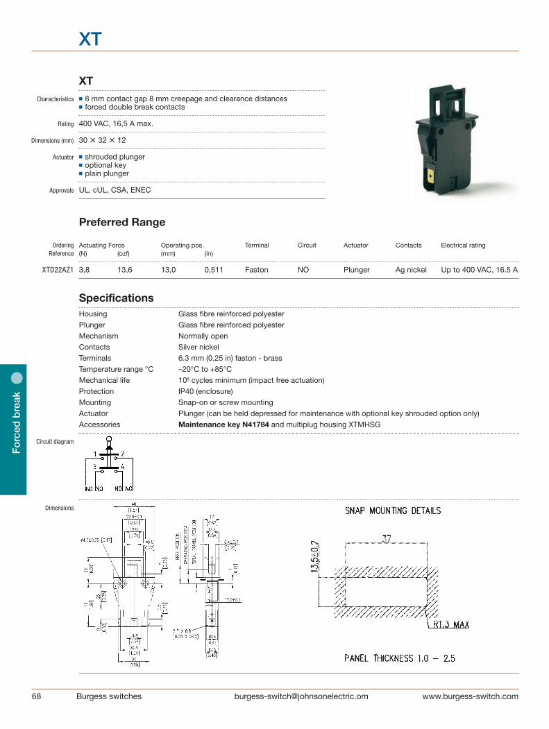
68 Burgess switches [email protected]
Fo
rced
bre
ak
XT
XT Characteristics ■ 8 mm contact gap 8 mm creepage and clearance distances ■ forced double break contacts
Rating 400 VAC, 16,5 A max.
Dimensions (mm) 30 • 32 • 12
Actuator ■ shrouded plunger ■ optional key ■ plain plunger
Approvals UL, cUL, CSA, ENEC
Preferred Range
Ordering Actuating Force Operating pos. Terminal Circuit Actuator Contacts Electrical rating Reference (N) (ozf) (mm) (in)
XTD22AZ1 3,8 13,6 13,0 0,511 Faston NO Plunger Ag nickel Up to 400 VAC, 16.5 A
Specifications Housing Glass fibre reinforced polyester Plunger Glass fibre reinforced polyester Mechanism Normally open Contacts Silver nickel Terminals 6.3 mm (0.25 in) faston - brass Temperature range °C –20°C to +85°C Mechanical life 106 cycles minimum (impact free actuation) Protection IP40 (enclosure) Mounting Snap-on or screw mounting Actuator Plunger (can be held depressed for maintenance with optional key shrouded option only) Accessories Maintenance key N41784 and multiplug housing XTMHSG
Circuit diagram
Dimensions

[email protected] switches
Fo
rced b
reak
XT
Recommended maximum electrical ratings
Voltage Load Inductive load Horsepower Approval (max) (A)
125 VAC 15.5 (0.75 pf) - - UL 1054/CSA 22.2 No. 55 - 100,000 operations 250 VAC 15.5 (0.75 pf) - - UL 1054/CSA 22.2 No. 55 - 100,000 operations 125 VAC - - 1⁄2 HP (0.45 pf) UL 1054 - Horsepower- 100,000 operations 250 VAC - - 1⁄2 HP (0.45 pf) UL 1054 - Horsepower- 100,000 operations 125 VAC - - 11⁄2 HP (0.45 pf) UL 1054 - Horsepower- 100,000 operations 250 VAC - - 11⁄2 HP (0.45 pf) UL 1054 - Horsepower- 100,000 operations 30 VAC 0,5 - - EN.60158-1 T85 (°C) 50,0000 operations 400 VAC 16,5 8 - EN.60158-1 T85 (°C) 50,0000 operations 30 VDC 0,5 - - UL 1054/CSA 22.2 No. 55 - 6,000 operations
Basic type XTD
Terminals 22 6.3 • 0.8 mm faston terminals A 100 k operations at 15:5 A 250 VAC, UL114 478
Form – Without identification: snap-on mounting with shroud J Snap-on mounting without shroud P Without shroud, without snap-on mounting K
Approvals Z1 UL, cUL, CSA and ENEC
Ordering Reference
Operating Characteristics Actuating Release Free Operating Total Travel Over Actuator Reference Force Force Position Position Position travel Maximum Minimum Maximum Maximum (N) (ozf) (N) (ozf) (mm) (in) (mm) (in) (mm) (in)
Plunger XTD22AZ1 3,8 13,600 5,8 20,8 18,0 0,708 13,0 ± 0.4 0,511 ± 0.016 10,0 0,394 3,0 0,118 ( ± 0.5) ( ± 3.5) (main contact) 12,6 0,496 (low voltage contact)
Example: XTD 22 J Z1
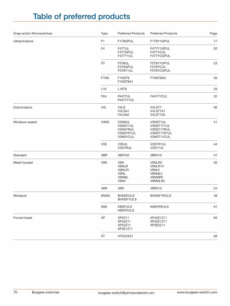
70 Burgess switches [email protected]
Snap-action Microswitches Type Preferred Products Preferred Products Page
Ultraminiature F1 F1T8GPUL F1T8Y1GPUL 17
F4 F4T7UL F4T7Y1GPUL 20 F4T7GPUL F4T7YCUL F4T7Y1UL F4T7YCGPUL
F5 F5T8UL F5T8Y1GPUL 23 F5T8GPUL F5T8YCUL F5T8Y1UL F5T8YCGPUL
F1NS F1NST8 F1NST8AC 26 F1NST8A1
L16 L16T8 29
FK4 FK4T7UL FK4T7YCUL 32 FK4T7Y1UL
Subminiature V4L V4LS V4LST7 36 V4LSA1 V4LST7A1 V4LSA2 V4LST7A2
Miniature sealed V3NS V3NSUL V3NST1UL 41 V3NSY1UL V3NST1Y1UL V3NSYRUL V3NST1YRUL V3NSYR1UL V3NST1YR1UL V3NSYCUL V3NST1YCUL
V3S V3SUL V3SYR1UL 44 V3SYRUL V3SY1UL
Standard 3BR 3BR103 3BR510 47
Metal housed V9N V9N V9NLRV 50 V9NLR V9NLR1V V9NLR1 V9NLV V9NL V9NMLV V9NML V9NMRV V9NV V9NMLRV
4BR 4BR 4BR510 54
Miniature BVM3 BVM3FULS BVM3FYRULS 58 BVM3FYULS
KB5 KB5FULS KB5FKRULS 61 KB5FKULS
Forced break XP XP2Z11 XP42E1Z11 65 XP42Z11 XP52E1Z11 XP52Z11 XP2E2Z11 XP2E1Z11 XT XTD22AZ1 68
Table of preferred products
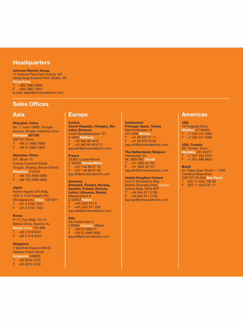
The data used in this Product Overview may be used as a guideline only. Specific operational characteristics of our products may vary according to individual applications. It is strongly recommended that specific operating conditions are clarified with Johnson Electric before application.
Johnson Electric Terms and Conditions of Sale apply.
All data may be subject to change without notice.
HeadquartersJohnson Electric Group12 Science Park East Avenue, 6/FHong Kong Science Park, Shatin, NTHong KongT +852 2663 6688F +852 2897 2054e-mail: [email protected]
Sales Offices
AsiaShanghai, China No. 1, Lane 10800, Songze Avenue, Qingpu Industrial Zone Shanghai 201700200122 China T +86 21 5882 2880 F +86 21 5882 2800
Shenzhen China2/F., Block 10Furong Industrial EstateXinqiao, Shajing, Baoan DistrictShenzhen 518125T +86 755 2990 0886F +86 755 2990 0890
Japan Keihin Higashi-Ohi Bldg. 10/F, 2-13-8 Higashi-Ohi Shinagawa-ku Tokyo 140-0011 T +81 3 5762 1031 F +81 3 5762 1032
Korea 6th Fl, Fine Bldg. 701-6 Banpo-Dong, Seocho-Ku Seoul, Korea 137-808 T +82 2 518 8341 F +82 2 518 8342
Singapore 1 Maritime Square #09-02, Harbour Front CentreSingapore 048623 T +65 6224 7570 F +65 6224 4538
EuropeAustriaCzech Republic, Hungary, Slo-vakia, Slovenia Linzer Bundesstrasse 101A-5023 SalzburgT +43 662 88 4910F +43 662 88 4910 [email protected]
France 10 Bld. Louise MichelF-92230 GennevilliersT +33 1 46 88 07 70F +33 1 46 88 07 [email protected] GermanyDenmark, Finland, Norway, Sweden, Poland, Estonia, Lativa, Lithuania, RussiaWeissenpferd 9D-58553 HalverT +49 2353 911 0F +49 2353 911 [email protected]
Italy Via Cadamosto 3I-20094 Corsico, MilanoT +39 02 4869 21F +39 02 4860 [email protected]
SwitzerlandPortugal, Spain, Turkey Bahnhofstrasse 18CH-3280 MurtenT +41 26 672 71 11F +41 26 670 19 [email protected]
The Netherlands/Belgium Hanzeweg 12c NL-2803 MC GoudaT +31 1825 43 154F +31 1825 43 [email protected]
United Kingdom/Ireland Unit 5, Woodstock Way, Boldon Business Park, BoldonTyne & Wear, NE35 9PFT +44 844 811 2130F +44 844 811 [email protected]
Americas USA 10 Progress DriveShelton, CT 06484 T +1 203 447 5362 F +1 203 447 5383
USA, Canada 801 Scholz Drive Vandalia, OH 45377 T +1 937 454 2345 F +1 937 898 8624
BrazilAv. Papa Joao Paulo I - 1256Cumbica-BuarulhosCEP 07170-350 Sao PauloT (55) 11-643 156 00F (55) 11-643 247 11
Johnson Electric Group
12 Science Park East Avenue, 6/F
Hong Kong Science Park, Shatin, NT
Hong Kong
Tel : +852 2663 6688
Fax: +852 2897 2054
Website: www.johnsonelectric.com
IPG220/10/E/01
Burg
ess Sw
itch Catalo
gJo
hnson E
lectric