Embed Size (px)
Citation preview

10 Edition 04.10l
AGA
Industrial & Commercial Thermal
Technical Information · GB
• Automatic burner control unit, ignition transformer, indicators and operating controls in a space-saving metal housing which replaces the local burner control cabinet
• For directly ignited burners of up to 350 kW in continuous operation pursuant to EN 746-2
• Display of the program status, unit parameters and flame signal; Manual mode for burner adjustment and for diagnostic purposes
• Visualisation and adaptation to the specific application via the PC programming and diagnostic software BCSoft to simplify logistics management.
Burner control unit BCU 440
BCU 440 · Edition 04.10l 2
▼ = To be continued
ContentsBurner control unit BCU 440 . . . . . . . . . . . . . . . . . . . . . . . . 1Contents . . . . . . . . . . . . . . . . . . . . . . . . . . . . . . . . . . . . . . . . . . . . 21 Application . . . . . . . . . . . . . . . . . . . . . . . . . . . . . . . . . . . . . . . . 41.1 Examples of application . . . . . . . . . . . . . . . . . . . . . . . . . . . 6
1.1.1 Atmospheric burners . . . . . . . . . . . . . . . . . . . . . . . . . . . . . . . . . .61.1.2 BCU 440: Modulating-controlled burner . . . . . . . . . . . . . 7
2 Certification . . . . . . . . . . . . . . . . . . . . . . . . . . . . . . . . . . . . . . . 82.1 EC type-tested and certified. . . . . . . . . . . . . . . . . . . . . . . 82.2 AGA . . . . . . . . . . . . . . . . . . . . . . . . . . . . . . . . . . . . . . . . . . . . . . . . 82.3 CSA . . . . . . . . . . . . . . . . . . . . . . . . . . . . . . . . . . . . . . . . . . . . . . . . 82.4 FM . . . . . . . . . . . . . . . . . . . . . . . . . . . . . . . . . . . . . . . . . . . . . . . . . 82.5 Approval for Russia . . . . . . . . . . . . . . . . . . . . . . . . . . . . . . . . 8
3 Function . . . . . . . . . . . . . . . . . . . . . . . . . . . . . . . . . . . . . . . . . . . 93.1 Connection diagram . . . . . . . . . . . . . . . . . . . . . . . . . . . . . . . 9
3.1.1 Zonal series wiring. . . . . . . . . . . . . . . . . . . . . . . . . . . . . . . . . . . 103.2 Program sequence. . . . . . . . . . . . . . . . . . . . . . . . . . . . . . . . 113.3 Program status and fault messages. . . . . . . . . . . . . .12
4 Parameters . . . . . . . . . . . . . . . . . . . . . . . . . . . . . . . . . . . . . . .134.1 Scanning the parameters. . . . . . . . . . . . . . . . . . . . . . . . .134.2 Flame control . . . . . . . . . . . . . . . . . . . . . . . . . . . . . . . . . . . . .14
4.2.1 Burner flame signal. . . . . . . . . . . . . . . . . . . . . . . . . . . . . . . . . . 144.2.2 Switch-off threshold of the flame amplifier. . . . . . . . . 14
4.3 Behaviour during start-up . . . . . . . . . . . . . . . . . . . . . . . .154.3.1 Safety time on start-up tSA . . . . . . . . . . . . . . . . . . . . . . . . . 15
4.4 Behaviour during operation. . . . . . . . . . . . . . . . . . . . . . .164.4.1 Safety time during operation tSB . . . . . . . . . . . . . . . . . . . . 164.4.2 Fault lock-out or restart . . . . . . . . . . . . . . . . . . . . . . . . . . . . . 164.4.3 rogram status when the most recent fault occurred 17
5 Selection . . . . . . . . . . . . . . . . . . . . . . . . . . . . . . . . . . . . . . . . .185.1 Determining the safety time tSA . . . . . . . . . . . . . . . . . .18
5.1.1 Calculating the safety time tSA . . . . . . . . . . . . . . . . . . . . . 185.2 Selection table . . . . . . . . . . . . . . . . . . . . . . . . . . . . . . . . . . . .19
5.2.1 Type code. . . . . . . . . . . . . . . . . . . . . . . . . . . . . . . . . . . . . . . . . . . . 19
6 Project planning information . . . . . . . . . . . . . . . . . . . . 206.1 Cable selection . . . . . . . . . . . . . . . . . . . . . . . . . . . . . . . . . . 20
6.1.1 Ignition cable . . . . . . . . . . . . . . . . . . . . . . . . . . . . . . . . . . . . . . . . 206.1.2 Ionisation cable . . . . . . . . . . . . . . . . . . . . . . . . . . . . . . . . . . . . . 206.1.3 UV cable . . . . . . . . . . . . . . . . . . . . . . . . . . . . . . . . . . . . . . . . . . . . . 20
6.2 Ignition electrode . . . . . . . . . . . . . . . . . . . . . . . . . . . . . . . . 206.2.1 Electrode gap . . . . . . . . . . . . . . . . . . . . . . . . . . . . . . . . . . . . . . . 206.2.2 Star electrodes . . . . . . . . . . . . . . . . . . . . . . . . . . . . . . . . . . . . . . 20
6.3 Safety interlocks (Limits) . . . . . . . . . . . . . . . . . . . . . . . . . 216.4 Protection of safety-relevant outputs . . . . . . . . . . . . 216.5 Reset . . . . . . . . . . . . . . . . . . . . . . . . . . . . . . . . . . . . . . . . . . . . . . 21
6.5.1 Parallel reset. . . . . . . . . . . . . . . . . . . . . . . . . . . . . . . . . . . . . . . . . .216.5.2 Permanent remote reset . . . . . . . . . . . . . . . . . . . . . . . . . . . . .216.5.3 Automatic remote reset (PLC) . . . . . . . . . . . . . . . . . . . . . . .216.5.4 Burner start. . . . . . . . . . . . . . . . . . . . . . . . . . . . . . . . . . . . . . . . . . 226.5.5 Restart and start-up attempts . . . . . . . . . . . . . . . . . . . . . . 22
6.6 Fault signalling . . . . . . . . . . . . . . . . . . . . . . . . . . . . . . . . . . .226.7 Overload protection. . . . . . . . . . . . . . . . . . . . . . . . . . . . . . .226.8 Installation. . . . . . . . . . . . . . . . . . . . . . . . . . . . . . . . . . . . . . . .226.9 Wiring . . . . . . . . . . . . . . . . . . . . . . . . . . . . . . . . . . . . . . . . . . . . .236.10 BCU switched off . . . . . . . . . . . . . . . . . . . . . . . . . . . . . . . .246.11 Furnace control . . . . . . . . . . . . . . . . . . . . . . . . . . . . . . . . .246.12 Mains switch . . . . . . . . . . . . . . . . . . . . . . . . . . . . . . . . . . . .246.13 Note on EC type-examination. . . . . . . . . . . . . . . . . . .246.14 Changing parameters . . . . . . . . . . . . . . . . . . . . . . . . . . .25
7 Flame control . . . . . . . . . . . . . . . . . . . . . . . . . . . . . . . . . . . . .268 Accessories . . . . . . . . . . . . . . . . . . . . . . . . . . . . . . . . . . . . . . .278.1 High-voltage cable . . . . . . . . . . . . . . . . . . . . . . . . . . . . . . . 278.2 BCSoft . . . . . . . . . . . . . . . . . . . . . . . . . . . . . . . . . . . . . . . . . . . . 278.3 “Changed parameters” stickers. . . . . . . . . . . . . . . . . . . 278.4 External securing bar . . . . . . . . . . . . . . . . . . . . . . . . . . . . .288.5 Fastening set . . . . . . . . . . . . . . . . . . . . . . . . . . . . . . . . . . . . .28
BCU 440 · Edition 04.10l 3
▼ = To be continued
8.6 Radio interference suppressed electrode adapters . . . . . . . . . . . . . . . . . . . . . . . . . . . . . . . . . . . . . . . . . . . . . .28
9 Technical data . . . . . . . . . . . . . . . . . . . . . . . . . . . . . . . . . . . 299.1 Housing dimensions . . . . . . . . . . . . . . . . . . . . . . . . . . . . . . 319.2 Operating controls. . . . . . . . . . . . . . . . . . . . . . . . . . . . . . . . 31
10 Legend . . . . . . . . . . . . . . . . . . . . . . . . . . . . . . . . . . . . . . . . . .3211 Glossary . . . . . . . . . . . . . . . . . . . . . . . . . . . . . . . . . . . . . . . . 3311.1 Waiting time tW . . . . . . . . . . . . . . . . . . . . . . . . . . . . . . . . . .3311.2 Safety time on start-up tSA . . . . . . . . . . . . . . . . . . . . . .3311.3 Ignition time tZ . . . . . . . . . . . . . . . . . . . . . . . . . . . . . . . . . .3311.4 Flame simulation/Flame simulation delay time tLV . . . . . . . . . . . . . . . . . . . . . . . . . . . . . . . . . . . . . . . . . . . . . . . . . . . . .3311.5 Safety time during operation tSB . . . . . . . . . . . . . . . .3411.6 Flame signal . . . . . . . . . . . . . . . . . . . . . . . . . . . . . . . . . . . . .3411.7 Fault lock-out . . . . . . . . . . . . . . . . . . . . . . . . . . . . . . . . . . . .3411.8 Safety interlocks (Limits) . . . . . . . . . . . . . . . . . . . . . . . .3411.9 Gas valve V1 . . . . . . . . . . . . . . . . . . . . . . . . . . . . . . . . . . . . .3411.10 Continuous operation . . . . . . . . . . . . . . . . . . . . . . . . . .34

BCU 440 · Edition 04.10l 4
Application
1 ApplicationBurner control unit BCU 440 controls, ignites and mon-itors gas burners in continuous operation.
It can be used for directly ignited industrial burners of up to 350 kW. The BCU is installed near the burner to be monitored.
The program status, the unit parameters and the level of the flame signal can be read directly from the unit.
If the local requirements on the burner control unit change, the PC software BCSoft can be adjusted to the unit parameters of the application by using the optical interface.
The service personnel is supported by a convenient vis-ualisation system of the input and output signals and the error history.
▼
The BCU unites the functionally interrelated com-ponents of auto-matic burner con-trol unit, ignition transformer, Man-ual/Automatic mode and display of operating and fault statuses in a compact metal housing.
BCU 440 · Edition 04.10l 5
Application
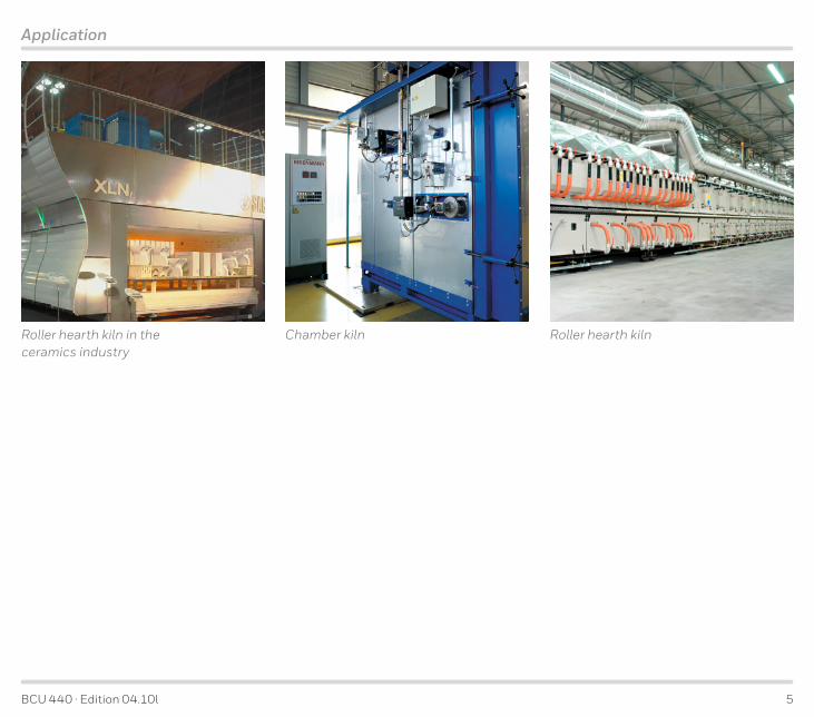
Roller hearth kilnRoller hearth kiln in the ceramics industry
Chamber kiln

BCU 440 · Edition 04.10l 6
Application
1 .1 Examples of application
1 .1 .1 Atmospheric burnersControl: ON/OFF
The burner is ignited by the ignition electrode and is monitored by the ionisation electrode. In the event of a flame failure during start-up, an immediate fault lock-out occurs. In the event of a flame failure during opera-tion, an immediate fault lock-out or a restart occurs, depending on the unit parameter settings.
BCU 440
L1, N, PE
1
µC
ZAI
12
1819
3
9
VAS
PLC

BCU 440 · Edition 04.10l 7
Application
1 .1 .2 BCU 440: Modulating-controlled burnerControl: continuous.
Modulating control of the gas flow rate with a constant air flow rate. The burners start at low-fire rate, and the actuator IC 20 controls the burner capacity via the lin-ear flow control LFC after the operating state has been signalled.
BCU 440
L1, N, PE
mA
BIO/BIC
VAS
µC
1
12
1819
3
9
AKT
AKT
BCU 440
BIO/BIC
VAS
µC
1
12
1819
3
9
AKT
AKT
BVGIC
20
+ LF
CM
PLC
BCU 440 · Edition 04.10l 8
Certification
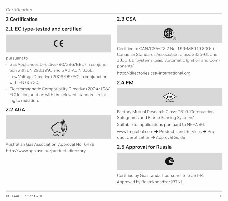
2 Certification2 .1 EC type-tested and certified
pursuant to
– Gas Appliances Directive (90/396/EEC) in conjunc-tion with EN 298:1993 and GAD-AC N 316E,
– Low Voltage Directive (2006/95/EC) in conjunction with EN 60730,
– Electromagnetic Compatibility Directive (2004/108/EC) in conjunction with the relevant standards relat-ing to radiation.
2 .2 AGA
AGA
Australian Gas Association, Approval No.: 6478
http://www.aga.asn.au/product_directory
2 .3 CSA
Certified to CAN/CSA–22.2 No. 199-M89 (R 2004), Canadian Standards Association Class: 3335-01 and 3335-81 “Systems (Gas)-Automatic Ignition and Com-ponents”
http://directories.csa-international.org
2 .4 FM
Factory Mutual Research Class: 7610 “Combustion Safeguards and Flame Sensing Systems”.
Suitable for applications pursuant to NFPA 86.
www.fmglobal.com Products and Services Pro-duct Certification Approval Guide
2 .5 Approval for Russia
Certified by Gosstandart pursuant to GOST-R.
Approved by Rostekhnadzor (RTN).

BCU 440 · Edition 04.10l 9
PE
Z I
1 2 3 5 PE 7 8 9 12 13 16 17 18 19 20
N n s
s1
N
88 c1
BCU 440
V1
7 8 9
F1
v1 c2
max. 2 A, 253 V
max. 2 A, 253 V
V1 C N S
C
ϑ
L1 (L1)N (L2)
OI
Function
3 Function3 .1 Connection diagramFor cable selection and wiring – see Project planning information.
For the explanation of symbols – see Legend.

BCU 440 · Edition 04.10l 10
1 2 3 5 PE 7 8 9 12 13 16 17 18 19 20
N n s
s1
N
88c1
BCU 440
V1
F1
v1c2
max. 2 A,253 V
max. 2 A,253 V
V1 C N S
C
OI
1
ZI
1 2 3 5 PE 7 8 9 12 13 16 17 18 19 20
N n s
s1
N
88c1
BCU 440
V1
F1
v1c2
max. 2 A,253 V
max. 2 A,253 V
V1 C N S
C
OI
2
ZI
1 2 3 5 PE 7 8 9 12 13 16 17 18 19 20
N n s
s1
N
88c1
BCU 440
V1
F1
v1c2
max. 2 A,253 V
max. 2 A,253 V
V1 C N S
C
OI
nZ
I
L1(L1)
L2(L1) PE
ϑ
Function
3 .1 .1 Zonal series wiringFor cable selection and wiring – see Project planning information.
For the explanation of sym-bols – see Legend.
BCU 440 · Edition 04.10l 11
Function
01
02
04
Switch on BCU 440
Start-up with ϑ-signal
Safety interlocks (Limits)
In the event of fault signal: reset
Flame simulation check
In the event of flame failure: restart or
fault lock-out
Operation signalling contact closes
Safety time tSA running (P22), ignition in
process, V1 opens
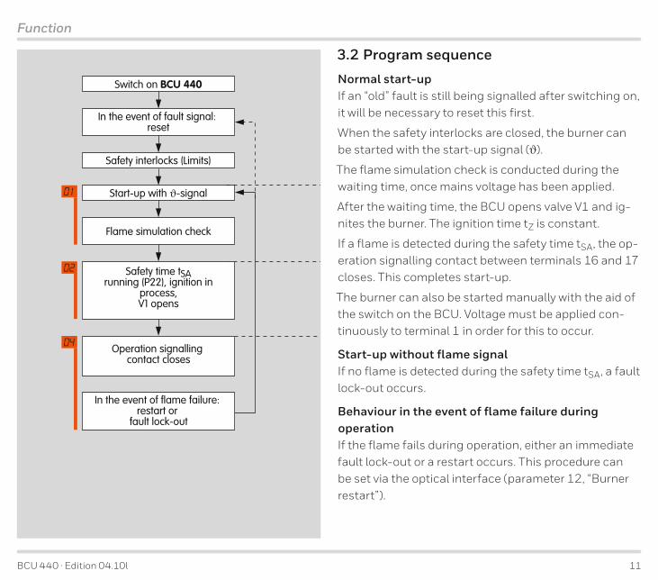
3 .2 Program sequence
Normal start-upIf an “old” fault is still being signalled after switching on, it will be necessary to reset this first.
When the safety interlocks are closed, the burner can be started with the start-up signal (ϑ).
The flame simulation check is conducted during the waiting time, once mains voltage has been applied.
After the waiting time, the BCU opens valve V1 and ig-nites the burner. The ignition time tZ is constant.
If a flame is detected during the safety time tSA, the op-eration signalling contact between terminals 16 and 17 closes. This completes start-up.
The burner can also be started manually with the aid of the switch on the BCU. Voltage must be applied con-tinuously to terminal 1 in order for this to occur.
Start-up without flame signalIf no flame is detected during the safety time tSA, a fault lock-out occurs.
Behaviour in the event of flame failure during operationIf the flame fails during operation, either an immediate fault lock-out or a restart occurs. This procedure can be set via the optical interface (parameter 12, “Burner restart”).
BCU 440 · Edition 04.10l 12
Function
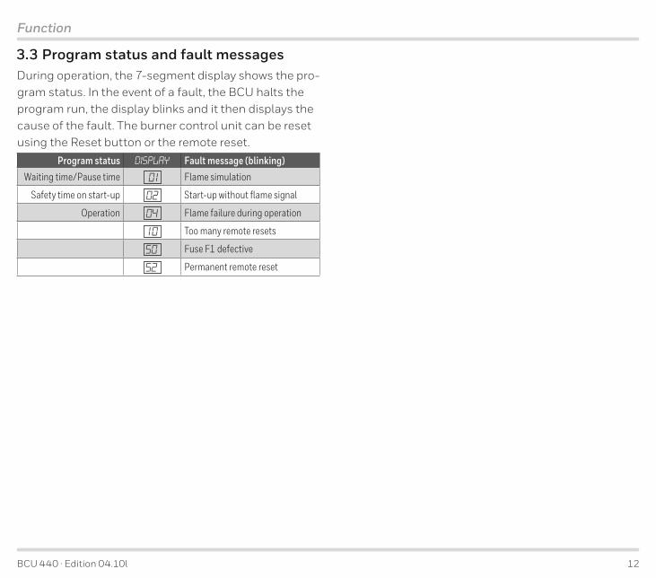
3 .3 Program status and fault messagesDuring operation, the 7-segment display shows the pro-gram status. In the event of a fault, the BCU halts the program run, the display blinks and it then displays the cause of the fault. The burner control unit can be reset using the Reset button or the remote reset.
Program status DISPLAY Fault message (blinking)Waiting time/Pause time 01 Flame simulation
Safety time on start-up 02 Start-up without flame signal
Operation 04 Flame failure during operation
10 Too many remote resets
50 Fuse F1 defective
52 Permanent remote reset
BCU 440 · Edition 04.10l 13
Parameters
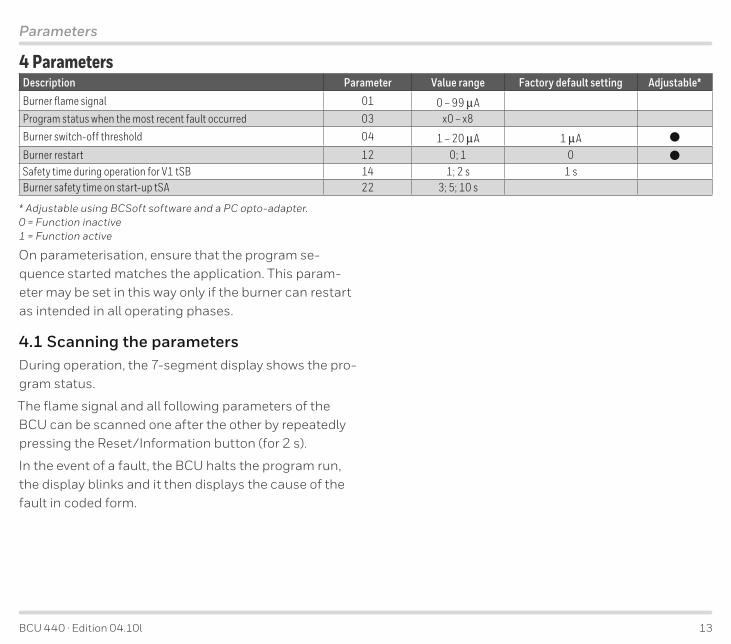
4 ParametersDescription Parameter Value range Factory default setting Adjustable*Burner flame signal 01 0 – 99 µAProgram status when the most recent fault occurred 03 x0 – x8 Burner switch-off threshold 04 1 – 20 µA 1 µA
Burner restart 12 0; 1 0
Safety time during operation for V1 tSB 14 1; 2 s 1 sBurner safety time on start-up tSA 22 3; 5; 10 s
* Adjustable using BCSoft software and a PC opto-adapter.0 = Function inactive1 = Function active
On parameterisation, ensure that the program se-quence started matches the application. This param-eter may be set in this way only if the burner can restart as intended in all operating phases.
4 .1 Scanning the parametersDuring operation, the 7-segment display shows the pro-gram status.
The flame signal and all following parameters of the BCU can be scanned one after the other by repeatedly pressing the Reset/Information button (for 2 s).
In the event of a fault, the BCU halts the program run, the display blinks and it then displays the cause of the fault in coded form.
BCU 440 · Edition 04.10l 14
Parameters
4 .2 Flame control
4 .2 .1 Burner flame signalParameter 01
Flame signal of the burner, display in µA, measuring range: 0 – 30 µA.
4 .2 .2 Switch-off threshold of the flame amplifierParameter 04
The sensitivity at which the burner control unit still de-tects a flame can be set between 1 and 20 µA.
The measured flame signal of the system’s “own” burner should be at least 3 µA (empirical value) higher than the set switch-off threshold.
BCU 440 · Edition 04.10l 15
Parameters
4 .3 Behaviour during start-up
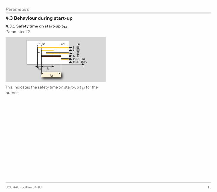
4 .3 .1 Safety time on start-up tSA Parameter 22
tSA
tZtW
8801ϑ
t
179
18-19
1216-17
02 04
This indicates the safety time on start-up tSA for the burner.
BCU 440 · Edition 04.10l 16
Parameters
4 .4 Behaviour during operation
4 .4 .1 Safety time during operation tSB Parameter 14
This indicates the safety time during operation tSB for valve V1.
The default in accordance with EN 298 is 1 s.
The BCU has also the available option of tSB of 2 s. Pro-longing the time increases the installation availability in the case of brief-duration signal fades (e.g. fades of the flame signal).
In accordance with EN 746-2, the safety time of the installation during operation (including closing time of the valves) may not exceed 3 s.
Note the requirements of the Standards!
4 .4 .2 Fault lock-out or restartParameter 12
This parameter determines whether the BCU starts a one-off restart or performs an immediate fault lock-out for the burner after an installation fault (flame failure or failure of air flow).
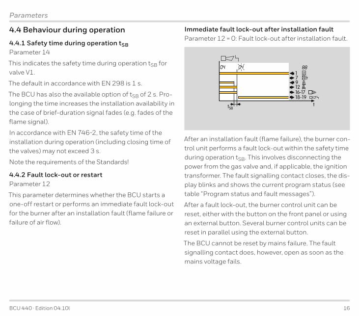
Immediate fault lock-out after installation faultParameter 12 = 0: Fault lock-out after installation fault.
88ϑ
t
179
18-19
1216-17
tSB
04 04
After an installation fault (flame failure), the burner con-trol unit performs a fault lock-out within the safety time during operation tSB. This involves disconnecting the power from the gas valve and, if applicable, the ignition transformer. The fault signalling contact closes, the dis-play blinks and shows the current program status (see table “Program status and fault messages”).
After a fault lock-out, the burner control unit can be reset, either with the button on the front panel or using an external button. Several burner control units can be reset in parallel using the external button.
The BCU cannot be reset by mains failure. The fault signalling contact does, however, open as soon as the mains voltage fails.

BCU 440 · Edition 04.10l 17
Parameters
Restart following flame failureParameter 12 = 1: Restart after installation fault.
tSA
tZ
tW
8801ϑ
t
179
18-19
1216-17
02
tSB
0404
> 2 s
1x
If the BCU detects an installation fault (flame failure) after a minimum operating time of 2 s, the valves are closed and the operation signalling contact is opened within time tSB.
The burner control unit now attempts to restart the burner once. If the burner does not function, a fault lock-out occurs. The display blinks and shows the cause of the fault.
In accordance with EN 746-2, a restart may be con-ducted only if the safety of the installation is not im-paired. Restart is recommended for burners which oc-casionally display unstable behaviour during operation.
The precondition for a restart is that activation of the restart allows the burner to restart as intended (in all operating phases). In this case, it must be ensured that the program sequence started by the BCU matches the application.
4 .4 .3 rogram status when the most recent fault occurredParameter 03
This indicates the program status in which the last burner fault occurred.
Example: The unit indicates that fuse F1 is defective with a blinking 50 .
Parameter 03 can now be used to scan in what program status the BCU was when the fault was detected.

BCU 440 · Edition 04.10l 18
Selection
5 Selection5 .1 Determining the safety time tSA The safety time on start-up tSA = 3 s, 5 s or 10 s should be indicated when ordering.
The details are based on the 1997 edition of EN 746-2.
EN 746-2PN tSA
70 kW 5 s
> 70 kW* 3 s
350 kW 10 s
> 350 kW** 5 s
0 ∞* 10 s
* PZ 0,1 x PN‘ PZmax = 350 kW
** PZ 0,33 x PN‘ PZmax = 350 kW
PN = Rated capacity
PZ = Pilot burner capacity (this is defined via the gas valve V1)
The safety time on start-up tSA depends on the burner type, the burner capacity and the respective applica-tion.
Burner with mechanical combustion air supply
Burner capacity
Natural draught burner with direct ignitionNatural draught burner with pilot burner
kWSafety time on
start-up tSA
s
5 .1 .1 Calculating the safety time tSA

BCU 440 · Edition 04.10l 19
Selection
5 .2 Selection table
-3 -5 -10 /1 /2 W R 1 2 3 4 GBBCU 440
= standard, = available
Order exampleBCU 440-3/1W1GB
5 .2 .1 Type code
Code DescriptionBCU Burner control unit4 Series 440 Basic version 40
-3-5-10
Safety time on start-up tSA [s]35
10
/1/2
Safety time in operation [s]12
WR
Mains voltage230 V AC, -15/+10%, 50/60 Hz115 V AC, -15/+10%, 50/60 Hz
1234
Ignition transformerTZI 5-15/100
TZI 7-25/20TZI 7,5-12/100
TZI 7,5-20/33GB Front fi lm in English with additional stickers in D, F, I, NL, E
BCU 440 · Edition 04.10l 20
Project planning information
6 Project planning information6 .1 Cable selectionUse mains cable suitable for the type of operation and complying with local regulations. Signal and control line: max. 2.5 mm2. Cable for burner ground/PE wire: 4 mm2. Do not route BCU cables in the same cable duct as frequency converter cables or cables emitting strong fields.
The connection cables are fed into the BCU housing via cable glands. The cable glands are equipped with mul-tiple seal inserts for cable diameters of up to 7 mm. For two cable glands, there is one seal insert each for cable diameters between 7 and 12 mm.
6 .1 .1 Ignition cableUse unscreened high-voltage cable (see Accessories). Cable length: max. 5 m, recommended < 1 m. Screw the ignition cable securely into the ignition transformer and run to the burner by the shortest possible route.
The longer the ignition cable, the lower the ignition capacity. Only use radio interference suppressed elec-trode adapters (with 1 kΩ resistor) for ignition electrodes (see Accessories). Do not lay ionisation cable and igni-tion cables together and lay them as far apart as pos-sible.
6 .1 .2 Ionisation cableUse unscreened high-voltage cable (see Accessories). Cable length: max. 50 m. Avoid external electrical in-terference. Install as far as possible from mains and ignition cables and interference from electro-magnetic sources. If possible, do not lay in a metal conduit. Sev-eral ionisation cables can be routed together.
6 .1 .3 UV cableCable length: max. 50 m. Avoid external electrical in-terference. Install as far as possible from mains and ignition cables and interference from electro-magnetic sources. If possible, do not lay in a metal conduit. Sev-eral UV cables can be routed together.
6 .2 Ignition electrode
6 .2 .1 Electrode gapGap between electrode and burner ground:
2 mm ± 0.5 mm.
6 .2 .2 Star electrodesWe recommend using 7.5 kV ignition transformers on burners with star electrodes.
BCU 440 · Edition 04.10l 21
Project planning information
6 .3 Safety interlocks (Limits)The limiters in the safety interlock (linking of all the rel-evant safety control and switching equipment for the use of the application, e.g. safety temperature limiter, minimum and maximum gas pressure, tightness con-trol) must isolate terminal 1 from the voltage supply. If fuse F1 has tripped, this is indicated by a blinking 50 on the display.
If the safety interlocks fail, an immediate program abort with switch-off of all outputs occurs (even during the safety time). If the safety interlocks are operational again or the unit is switched back on, the program run is restarted in standby.
6 .4 Protection of safety-relevant outputsWhen commissioning, do not switch the safety-relevant outputs to a short-circuit.
Before switching on, ensure that outputs 7 and 12 are not overloaded (> 3 A), using an ohmmeter, for example.
All safety-relevant outputs of the BCU are fused with an internal, non-replaceable fuse (see connection dia-grams). This affects the outputs for ignition and gas valve V1. In the event that the internal fuse for these outputs blows, the unit must be sent to the manufac-turer for repair.
6 .5 Reset
6 .5 .1 Parallel resetSeveral burner control units can be reset in parallel us-ing the external button. The BCU cannot be reset by mains failure.
6 .5 .2 Permanent remote resetPermanent remote reset gives rise to a malfunction. If a remote reset signal is permanently applied to terminal 3, 52 flashes on the display to indicate a fault.
Reset with a pulse < 1 s.
6 .5 .3 Automatic remote reset (PLC)In the case of automatic remote reset (PLC), the reset pulse duration should not exceed 1 second. Check compliance with Standards.
If a fault is acknowledged by remote reset too often, er-ror 10 (Too many remote resets) is displayed. The error can only be acknowledged with the Reset/Information button on the unit.
The burner malfunction must be remedied. The mal-function can not be remedied by changing the method of activation.
BCU 440 · Edition 04.10l 22
Project planning information
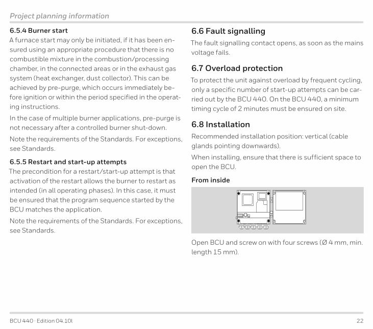
6 .5 .4 Burner startA furnace start may only be initiated, if it has been en-sured using an appropriate procedure that there is no combustible mixture in the combustion/processing chamber, in the connected areas or in the exhaust gas system (heat exchanger, dust collector). This can be achieved by pre-purge, which occurs immediately be-fore ignition or within the period specified in the operat-ing instructions.
In the case of multiple burner applications, pre-purge is not necessary after a controlled burner shut-down.
Note the requirements of the Standards. For exceptions, see Standards.
6 .5 .5 Restart and start-up attemptsThe precondition for a restart/start-up attempt is that activation of the restart allows the burner to restart as intended (in all operating phases). In this case, it must be ensured that the program sequence started by the BCU matches the application.
Note the requirements of the Standards. For exceptions, see Standards.
6 .6 Fault signallingThe fault signalling contact opens, as soon as the mains voltage fails.
6 .7 Overload protectionTo protect the unit against overload by frequent cycling, only a specific number of start-up attempts can be car-ried out by the BCU 440. On the BCU 440, a minimum timing cycle of 2 minutes must be ensured on site.
6 .8 InstallationRecommended installation position: vertical (cable glands pointing downwards).
When installing, ensure that there is sufficient space to open the BCU.
From inside
Open BCU and screw on with four screws (Ø 4 mm, min. length 15 mm).

BCU 440 · Edition 04.10l 23
Project planning information
From outside
163
mm
185 mm
7.28"
6.42
"
Screw on the closed unit to the rear with 4 self-tapping screws (enclosed).
Otherwise, mount with external securing bars or fasten-ing set (see Accessories).
6 .9 WiringElectrical connection via plug-in connection terminals (2.5 mm²) and plug-in cable glands. The latter can be removed in order to facilitate installation. The BCU is suitable for hard wiring only. Do not reverse phase and neutral conductor. Different phases of a three-phase current system must not be installed at the BCU. No voltage may be connected to the valve and ignition out-puts.

BCU 440 · Edition 04.10l 24
Project planning information
6 .10 BCU switched offIn general, the BCU cannot be activated when no mains voltage is applied or the burner control unit is switched off. The fault signalling contact is only closed when the unit is supplied with voltage and switched on.
If the unit is switched off, an immediate program abort with switch-off of all outputs occurs (even during the safety time). When the unit is switched on, the program run is restarted in standby.
6 .11 Furnace controlSwitch on the system to start up the furnace, then release the burner start via the safety interlocks and afterwards start the burner control so that the burner control unit may monitor the burners as intended. To shut down the furnace, first disconnect the burner control unit from the temperature control (burner ON signal), then disconnect the safety interlocks and finally switch off the system.
6 .12 Mains switchThe mains switch in the unit isolates the BCU on two poles from the mains. It does not meet the require-ments of EN 50156-1:2004 for a device to disconnect the power supply.
Although the mains switch cannot be used for discon-necting from the electrical power supply in accordance with EN 50156, it does allow the burner to be isolated functionally from the central control system. This func-tion is required for manual operation.
Disconnection for electrical maintenance work is to be implemented with an external switch per unit or group only, in accordance with Standard EN 50156.
6 .13 Note on EC type-examinationSince EN 298 (1993) does not describe all functions of the BCU, the operator is responsible for ensuring that all parameters and functions are matched to the re-spective application.
BCU 440 · Edition 04.10l 25
Project planning information
6 .14 Changing parametersIn certain cases, it may be necessary to change the de-fault settings. Using a separate software package and a PC opto-adapter, it is possible to modify certain pa-rameters on the BCU, such as the switch-off threshold of the flame amplifier or the behaviour in the event of a flame failure.
The software package with PC opto-adapter, as well as “Changed parameters” stickers, are available as acces-sories – see section entitled Accessories.
The unit parameters set at the factory are specified in the enclosed delivery note.
Document changed parameters in BCSoft using the protocol function and enclose the protocol with the plant documentation.
If a replacement is ordered for a BCU with changed pa-rameters, refer to the protocol for details.

BCU 440 · Edition 04.10l 26
Flame control
7 Flame controlWith ionisation sensor
The BCU generates an alternating voltage (230 V AC) between the sensing electrode and burner ground. The flame rectifies this voltage. Only the DC signal (> 1 µA) is detected by the burner control unit.
A flame cannot be simulated. Ignition and monitoring with a single electrode is possible.

BCU 440 · Edition 04.10l 27
Accessories
8 Accessories8 .1 High-voltage cableFZLSi 1/7 up to 180°C, Order No. 04250410.
FZLK 1/7 up to 80°C, Order No. 04250409.
8 .2 BCSoft
Opto-adapter including BCSoft CD-ROM, Order No. 74960437.
The current software can be downloaded from our In-ternet site at http://www.docuthek.com. To do so, you need to register in the DOCUTHEK.
8 .3 “Changed parameters” stickers
D-49018 Osnabrück, Germany
Achtung, geänderte Parameter!Die Angaben auf dem Typenschild gelten nicht mehr in vollem Umfang.Aktuelle Parameter direkt auslesen.
Important, changed parameters!The details on the type label are no longer completely accurate. Read the current parameters direct from the unit.
Attention, paramètres modifiés !Les informations figurant sur la plaque signalétique ne sont plus valables dans leur intégralité. Veuillez vous référer directement aux paramètres actualisés.
Affix below the type label on the BCU following changes to unit parameters set at the fac-tory.
100 pcs, Order No. 74921492.
BCU 440 · Edition 04.10l 28
Accessories
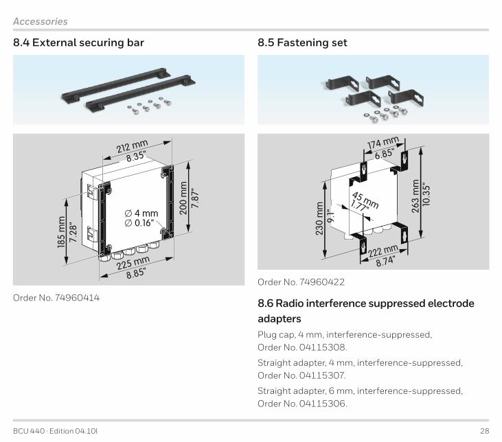
8 .4 External securing bar18
5 m
m7.
28"
200
mm
7.87
"
212 mm
� 4 mm� 0.16"
8.35"
225 mm
8.85"
Order No. 74960414
8 .5 Fastening set
174 mm
230
mm
45 mm 1.77"
6.85"
9.1"
222 mm
8.74"
263
mm
10.3
5"
Order No. 74960422
8 .6 Radio interference suppressed electrode adaptersPlug cap, 4 mm, interference-suppressed, Order No. 04115308.
Straight adapter, 4 mm, interference-suppressed, Order No. 04115307.
Straight adapter, 6 mm, interference-suppressed, Order No. 04115306.

BCU 440 · Edition 04.10l 29
Technical data
9 Technical dataMains voltage: 230 V AC. -15/+10%. 50/60 Hz. 115 V AC. -15/+10%. 50/60 Hz. for grounded and ungrounded mains.
Voltage to inputs and valve = mains voltage.
Signal and control line: max. 2.5 mm2 (AWG 14).
Cable for burner ground/PE wire: 4 mm2 (AWG 12).
Cable gland: 5 cable glands with multiple seal inserts for cable diam-eters of up to 7 mm, Each BCU is supplied for two cable glands with one seal insert each for cable diameters between 7 and 12 mm.
Input voltage of signal inputs:
Rated value 115 V AC 230 V ACSignal “1” 80 – 126.5 160 – 253Signal “0” 0 – 20 0 – 40Frequency 50/60 Hz 50/60 Hz
Inherent current:Signal „1“ typ. 2 mA
Power consumption: approx. 9 VA plus inherent con-sumption of the integrated ignition transformer (50/60 Hz).
Inherent consumption of ignition transformer:
Type Input230 V AC
Input115 V AC Output
TZI 5-15/100 0.45 (0.35)* A 0.9 (0.7)* A 5 kV15 (11)* mA
TZI 7-25/20 1.1 (0.8)* A 2.2 (1.6)* A 7 kV25 (18)* mA
TZI 7,5-20/33 0.9 (0.7)* A 1.8 (1.35)* A 7.5 kV20 (15)* mA
TZI 7,5-12/100 0.6 (0.45)* A 1.2 (0.9)* A 7.5 kV12 (9)* mA
* Values in brackets apply to 60 Hz.
Output current:
max. 1 A, cos ϕ = 1, for the valve outputs (or SRC out-puts),
but total current for valves and ignition transformer: max. 2.5 A.
Fail-safe inputs and outputs:
All the inputs and outputs marked “ ” (see 9 (Con-nection diagram)) may be used for safety tasks.
Operation and fault signalling contacts:
Signalling contact for mains voltage, max. 2 A, 253 V,
not internally fused.
▼
BCU 440 · Edition 04.10l 30
Technical data
Flame control: sensor voltage approx. 230 V AC, sensor current > 1 µA.
Length of sensor cable: max. 5 m (16.4 ft).
Fuses in unit: Fuse for protecting the air output (26): F1: 5 A, slow-acting, H pursuant to IEC 127-2/5.
21 (Protection of safety-relevant outputs), valve 1 and valve 2 outputs (terminals 7, 12 and 14): 3.15 A, slow-acting, not replaceable.
F3 (only for BCU.. A and C): 3.15 A, slow-acting, H pursuant to IEC 127-2/5.
Ambient temperature: -20 to +60°C (-4 to +140°F), climate: no condensation permitted.
Enclosure: IP 54 pursuant to IEC 529.
Number of operating cycles: Relay outputs: 250,000 pursuant to EN 298, Mains switch: 1,000, Reset/Information button: 1,000.
Weight: approx. 5 kg (11 lb) depending on version.

BCU 440 · Edition 04.10l 31
88
200
mm
(7.8
7") A
55mm
B
C
D
E
200 mm (7.87")
50mm(1.97") (2.17")
� 4,5 mm0.177"
163
mm
6.42
"
185 mm
7.28"
Technical data
9 .1 Housing dimensionsDie-cast aluminium housing with plug-in terminal blocks and plug-in M20 cable glands for input signals and optionally pre-assembled cables for output signals.
9 .2 Operating controlsA: Optical interface.
B: Labelling field for individual labelling of the system components.
C: 2-digit 7-segment display.
D: Mains switch.
E: Reset/Information button to reset the system after a fault or to scan parameters on the display.
BCU 440 · Edition 04.10l 32
Legend
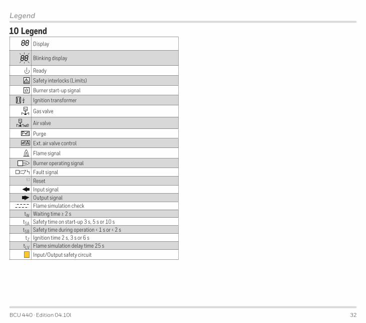
10 Legend88 Display
88 Blinking display
Ready
Safety interlocks (Limits)
Burner start-up signal
Ignition transformer
Gas valve
Air valve
P PurgeA Ext. air valve control
Flame signal
Burner operating signal
Fault signalResetInput signalOutput signalFlame simulation check
tW Waiting time ≥ 2 stSA Safety time on start-up 3 s, 5 s or 10 stSB Safety time during operation < 1 s or < 2 s
tZ Ignition time 2 s, 3 s or 6 stLV Flame simulation delay time 25 s
Input/Output safety circuit

BCU 440 · Edition 04.10l 33
Glossary
11 Glossary11 .1 Waiting time tW
tSA
tZtW
8801ϑ
t
179
18-19
1216-17
02 02
Once the start-up signal ϑ has been applied, the wait-ing time tW starts to elapse. During this time, a self-test is conducted to detect errors in internal and external circuit components. If no malfunction is detected, the burner will start up.
11 .2 Safety time on start-up tSA This refers to the period of time between switching on and switching off of the pilot gas valve V1, when no flame signal is detected. The safety time on start-up tSA (3, 5 or 10 s) is the minimum operating time of the burner and burner control unit.
11 .3 Ignition time tZ If no malfunction is detected during the waiting time tW, the ignition time tZ then starts to elapse. Voltage is supplied to the pilot gas valve V1 and the ignition trans-former and the burner is ignited. The duration of the ignition time is either 2, 3 or 7 seconds, depending on safety time tSA selected.
11 .4 Flame simulation/Flame simulation delay time tLV
tLV
8801ϑ
t
179
18-19
12 V116-17
01
An extraneous signal (flame simulation) is a flame sig-nal that is detected, although there should be no flame according to the program sequence. If such an extrane-ous signal is detected, the flame simulation delay time tLV starts to elapse. If the flame simulation is disconti-nued during the flame simulation delay time tLV, start-up can be initiated or operation continued. Otherwise, a fault lock-out occurs.

BCU 440 · Edition 04.10l 34
Glossary
11 .5 Safety time during operation tSB
88ϑ
t
179
18-19
1216-17
tSB
04 04
If the flame fails during operation, the valve outputs are disconnected within the safety time tSB.
The default safety time during operation tSB in accord-ance with EN 298 is 1 second. In accordance with EN 746-2, the safety time of the installation during opera-tion (including closing time of the valves) may not ex-ceed 3 s. Note the requirements of the Standards!
11 .6 Flame signalIf a flame is detected, the flame detector will supply a flame signal.
11 .7 Fault lock-outIn the event of a fault lock-out, the valve and the igni-tion transformer are disconnected from the electrical power supply, and a fault is signalled. Resetting must take place manually following a fault lock-out.
11 .8 Safety interlocks (Limits)The limiters in the safety interlock (linking of all the rel-evant safety control and switching equipment for the use of the application, e.g. safety temperature limiter, minimum/maximum gas pressure) must isolate input
from the voltage supply.
11 .9 Gas valve V1The start fuel flow rate for the burner is released by gas valve V1. It opens when the safety time on start-up tSA starts to elapse. It remains open until the burner is switched off again by a controlled shut-down or fault lock-out.
11 .10 Continuous operationThe gas burner runs continuously for more than 24 hours.
BCU 440 · Edition 04.10l
FeedbackFinally, we are offering you the opportunity to assess this “Technical Information (TI)” and to give us your opinion, so that we can improve our documents further and suit them to your needs.
ClarityFound information quicklySearched for a long timeDidn’t find informationWhat is missing?
ComprehensionCoherentToo complicatedNo answer
ScopeToo littleSufficientToo wideNo answer
No answer
NavigationI can find my way aroundI got “lost”No answer
UseTo get to know the productTo choose a productPlanningTo look for information
My scope of functionsTechnical departmentSalesNo answer
Remarks
Elster GmbH Postfach 2809 · 49018 Osnabrück Strotheweg 1 · 49504 Lotte (Büren) GermanyTel +49 541 1214-0 Fax +49 541 1214-370 [email protected]
ContactThe current addresses of our international agents are available on the Internet: www.kromschroeder.de/Weltweit.20.0.html?&L=1
We reserve the right to make technical modifications in the interests of progress.Copyright © 2016 Elster GmbH All rights reserved.
03
25
08
14