Embed Size (px)
Citation preview
© 2018 JETIR November 2018, Volume 5, Issue 11 www.jetir.org (ISSN-2349-5162)
JETIR1811A98 Journal of Emerging Technologies and Innovative Research (JETIR) www.jetir.org 778
Bus Detection Module For Blind People
K.Bhavana1 B.Lalitha2 k.lalitha3 1, 2, 3 Prasad V Potluri Siddhartha Institute Of Technology, Kanuru,Vijayawada, Andhra Pradesh, India
Approved by AICTE and Affiliated to JNTUK: Kakinada 1, 2, 3 Department of electrical and electronics
Abstract--This project will shed the light on the field
of transportation to improve the life quality of
visually impaired persons (VIPs) using Radio
Frequency module. The Idea behind this project is to
develop a prototype that would use the technological
advancements to assist the daily commuters,
especially visual impaired person to access public
transport.
This system will allow blind people to safely catch
buses and other transportation with the help of
vibrating device, alarm and a tactile interface through
a wireless communication system between the
transmitter and the receiver..
VIPs will have the opportunity to get information
about bus arrival and departure time as well as assist
the bus operator to know the presence of a VIP on the
road. The motivation behind this project is that buses
are vital in enabling blind people to participate fully
in society, access to facilities and services.
Index Terms - INTRODUCTION
This project will shed the light on the field of
transportation for the improvement of the life quality for
visually impaired persons (VIP’s) using the technology
like radio frequency module. The idea behind this project
is to develop a prototype that would use the technological
advancements to assist the daily commuters, especially
visual impaired person to access public transport.
This system will allow blind people to safely catch buses
with the help of vibrating device, alarm and a tactile
interface through a wireless communication system
between the transmitter and the receiver. VIP’s will have
the opportunity to get information about bus arrival and
departure time as well as assist the bus operator to know
the presence of a VIP on the road. The system is based on
a distributed model.
This system can be installed over the taxies, trains, public
buses, etc… all over the city so that people can very
easily communicate with them. This system, if
manufactured commercially, is very economic and thus
can be made available at the stores so that women,
children, senior citizens or any section of society can use
it. With few changes in the hardware and programming,
this prototype can be turned into a security device.
Looking towards the present scenario of the nation, this
device can be proved to be very useful, as far as women
security is concerned. Thus, this project presents a new
approach to bus identification system for VIP’s using RF.
HARD WARE COMPONENTS
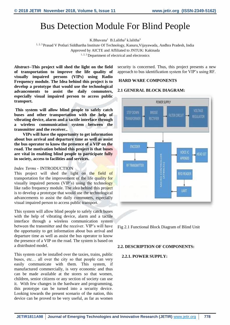
2.1 GENERAL BLOCK DIAGRAM:
Fig 2.1 Functional Block Diagram of Blind Unit
2.2. DESCRIPTION OF COMPONENTS:
2.2.1. POWER SUPPLY:
© 2018 JETIR November 2018, Volume 5, Issue 11 www.jetir.org (ISSN-2349-5162)
JETIR1811A98 Journal of Emerging Technologies and Innovative Research (JETIR) www.jetir.org 779
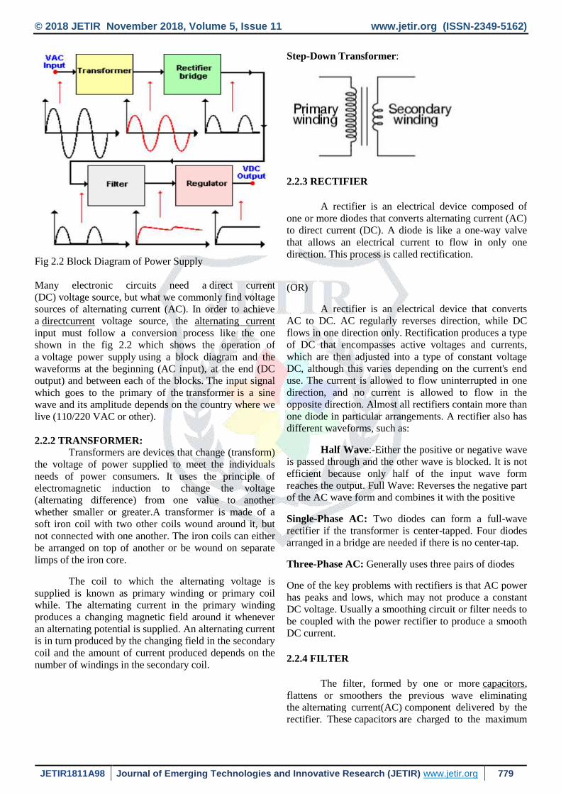
Fig 2.2 Block Diagram of Power Supply
Many electronic circuits need a direct current
(DC) voltage source, but what we commonly find voltage
sources of alternating current (AC). In order to achieve
a directcurrent voltage source, the alternating current
input must follow a conversion process like the one
shown in the fig 2.2 which shows the operation of
a voltage power supply using a block diagram and the
waveforms at the beginning (AC input), at the end (DC
output) and between each of the blocks. The input signal
which goes to the primary of the transformer is a sine
wave and its amplitude depends on the country where we
live (110/220 VAC or other).
2.2.2 TRANSFORMER: Transformers are devices that change (transform)
the voltage of power supplied to meet the individuals
needs of power consumers. It uses the principle of
electromagnetic induction to change the voltage
(alternating difference) from one value to another
whether smaller or greater.A transformer is made of a
soft iron coil with two other coils wound around it, but
not connected with one another. The iron coils can either
be arranged on top of another or be wound on separate
limps of the iron core.
The coil to which the alternating voltage is
supplied is known as primary winding or primary coil
while. The alternating current in the primary winding
produces a changing magnetic field around it whenever
an alternating potential is supplied. An alternating current
is in turn produced by the changing field in the secondary
coil and the amount of current produced depends on the
number of windings in the secondary coil.
Step-Down Transformer:
2.2.3 RECTIFIER
A rectifier is an electrical device composed of
one or more diodes that converts alternating current (AC)
to direct current (DC). A diode is like a one-way valve
that allows an electrical current to flow in only one
direction. This process is called rectification.
(OR)
A rectifier is an electrical device that converts
AC to DC. AC regularly reverses direction, while DC
flows in one direction only. Rectification produces a type
of DC that encompasses active voltages and currents,
which are then adjusted into a type of constant voltage
DC, although this varies depending on the current's end
use. The current is allowed to flow uninterrupted in one
direction, and no current is allowed to flow in the
opposite direction. Almost all rectifiers contain more than
one diode in particular arrangements. A rectifier also has
different waveforms, such as:
Half Wave:-Either the positive or negative wave
is passed through and the other wave is blocked. It is not
efficient because only half of the input wave form
reaches the output. Full Wave: Reverses the negative part
of the AC wave form and combines it with the positive
Single-Phase AC: Two diodes can form a full-wave
rectifier if the transformer is center-tapped. Four diodes
arranged in a bridge are needed if there is no center-tap.
Three-Phase AC: Generally uses three pairs of diodes
One of the key problems with rectifiers is that AC power
has peaks and lows, which may not produce a constant
DC voltage. Usually a smoothing circuit or filter needs to
be coupled with the power rectifier to produce a smooth
DC current.
2.2.4 FILTER
The filter, formed by one or more capacitors,
flattens or smoothers the previous wave eliminating
the alternating current(AC) component delivered by the
rectifier. These capacitors are charged to the maximum
© 2018 JETIR November 2018, Volume 5, Issue 11 www.jetir.org (ISSN-2349-5162)
JETIR1811A98 Journal of Emerging Technologies and Innovative Research (JETIR) www.jetir.org 780
voltage value that the rectifier can deliver and discharge
when the pulsating signal disappears .
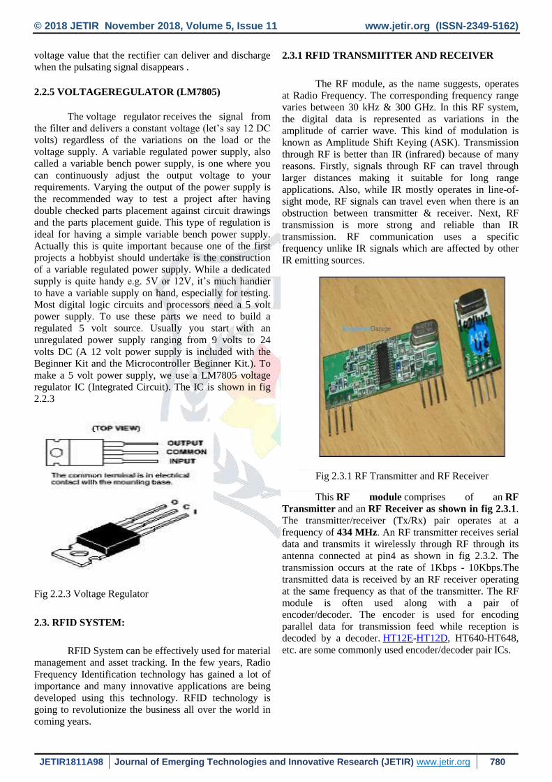
2.2.5 VOLTAGEREGULATOR (LM7805)
The voltage regulator receives the signal from
the filter and delivers a constant voltage (let’s say 12 DC
volts) regardless of the variations on the load or the
voltage supply. A variable regulated power supply, also
called a variable bench power supply, is one where you
can continuously adjust the output voltage to your
requirements. Varying the output of the power supply is
the recommended way to test a project after having
double checked parts placement against circuit drawings
and the parts placement guide. This type of regulation is
ideal for having a simple variable bench power supply.
Actually this is quite important because one of the first
projects a hobbyist should undertake is the construction
of a variable regulated power supply. While a dedicated
supply is quite handy e.g. 5V or 12V, it’s much handier
to have a variable supply on hand, especially for testing.
Most digital logic circuits and processors need a 5 volt
power supply. To use these parts we need to build a
regulated 5 volt source. Usually you start with an
unregulated power supply ranging from 9 volts to 24
volts DC (A 12 volt power supply is included with the
Beginner Kit and the Microcontroller Beginner Kit.). To
make a 5 volt power supply, we use a LM7805 voltage
regulator IC (Integrated Circuit). The IC is shown in fig
2.2.3
Fig 2.2.3 Voltage Regulator
2.3. RFID SYSTEM:
RFID System can be effectively used for material
management and asset tracking. In the few years, Radio
Frequency Identification technology has gained a lot of
importance and many innovative applications are being
developed using this technology. RFID technology is
going to revolutionize the business all over the world in
coming years.
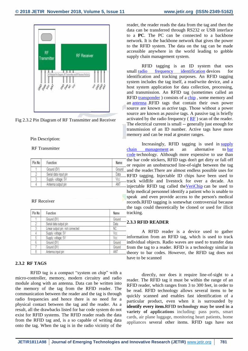
2.3.1 RFID TRANSMIITTER AND RECEIVER
The RF module, as the name suggests, operates
at Radio Frequency. The corresponding frequency range
varies between 30 kHz & 300 GHz. In this RF system,
the digital data is represented as variations in the
amplitude of carrier wave. This kind of modulation is
known as Amplitude Shift Keying (ASK). Transmission
through RF is better than IR (infrared) because of many
reasons. Firstly, signals through RF can travel through
larger distances making it suitable for long range
applications. Also, while IR mostly operates in line-of-
sight mode, RF signals can travel even when there is an
obstruction between transmitter & receiver. Next, RF
transmission is more strong and reliable than IR
transmission. RF communication uses a specific
frequency unlike IR signals which are affected by other
IR emitting sources.
Fig 2.3.1 RF Transmitter and RF Receiver
This RF module comprises of an RF
Transmitter and an RF Receiver as shown in fig 2.3.1.
The transmitter/receiver (Tx/Rx) pair operates at a
frequency of 434 MHz. An RF transmitter receives serial
data and transmits it wirelessly through RF through its
antenna connected at pin4 as shown in fig 2.3.2. The
transmission occurs at the rate of 1Kbps - 10Kbps.The
transmitted data is received by an RF receiver operating
at the same frequency as that of the transmitter. The RF
module is often used along with a pair of
encoder/decoder. The encoder is used for encoding
parallel data for transmission feed while reception is
decoded by a decoder. HT12E-HT12D, HT640-HT648,
etc. are some commonly used encoder/decoder pair ICs.
© 2018 JETIR November 2018, Volume 5, Issue 11 www.jetir.org (ISSN-2349-5162)
JETIR1811A98 Journal of Emerging Technologies and Innovative Research (JETIR) www.jetir.org 781
Fig 2.3.2 Pin Diagram of RF Transmitter and Receiver
Pin Description:
RF Transmitter
RF Receiver
2.3.2 RF TAGS
RFID tag is a compact “system on chip” with a
micro-controller, memory, modern circuitry and radio
module along with an antenna. Data can be written into
the memory of the tag from the RFID reader. The
communication between the reader and the tag is through
radio frequencies and hence there is no need for a
physical contact between the tag and the reader. As a
result, all the drawbacks listed for bar code system do not
exist for RFID systems. The RFID reader reads the data
from the RFID tag and, is a so capable of writing data
onto the tag. When the tag is in the radio vicinity of the
reader, the reader reads the data from the tag and then the
data can be transferred through RS232 or USB interface
to a PC. The PC can be connected to a backbone
network. It is the backbone network that gives the power
to the RFID system. The data on the tag can be made
accessible anywhere in the world leading to gobble
supply chain management system.
RFID tagging is an ID system that uses
small radio frequency identification devices for
identification and tracking purposes. An RFID tagging
system includes the tag itself, a read/write device, and a
host system application for data collection, processing,
and transmission. An RFID tag (sometimes called an
RFID transponder ) consists of a chip , some memory and
an antenna .RFID tags that contain their own power
source are known as active tags. Those without a power
source are known as passive tags. A passive tag is briefly
activated by the radio frequency ( RF ) scan of the reader.
The electrical current is small -- generally just enough for
transmission of an ID number. Active tags have more
memory and can be read at greater ranges.
Increasingly, RFID tagging is used in supply
chain management as an alternative to bar
code technology. Although more expensive to use than
the bar code stickers, RFID tags don't get dirty or fall off
or require an unobstructed line-of-sight between the tag
and the reader.There are almost endless possible uses for
RFID tagging. Injectable ID chips have been used to
track wildlife and livestock for over a decade. An
injectable RFID tag called theVeriChip can be used to
help medical personnel identify a patient who is unable to
speak and even provide access to the person's medical
records.RFID tagging is somewhat controversial because
the tags could theoretically be cloned or used for illicit
tracking.
2.3.3 RFID READER
A RFID reader is a device used to gather
information from an RFID tag, which is used to track
individual objects. Radio waves are used to transfer data
from the tag to a reader. RFID is a technology similar in
theory to bar codes. However, the RFID tag does not have to be scanned
directly, nor does it require line-of-sight to a
reader. The RFID tag it must be within the range of an
RFID reader, which ranges from 3 to 300 feet, in order to
be read. RFID technology allows several items to be
quickly scanned and enables fast identification of a
particular product, even when it is surrounded by
identify every item.RFID technology may be used in a
variety of applications including: pass ports, smart
cards, air plane luggage, monitoring heart patients, home
appliances several other items. RFID tags have not
© 2018 JETIR November 2018, Volume 5, Issue 11 www.jetir.org (ISSN-2349-5162)
JETIR1811A98 Journal of Emerging Technologies and Innovative Research (JETIR) www.jetir.org 782
replaced bar codes because of their cost and the need to individually
RFID technology uses digital data in an RFID
tag, made up of circuits containing a tiny antenna for
transferring information to an RFID transceiver. The
majority of RFID tags contain at least an integrated
circuit for modulating and demodulating radio frequency
and an antenna for transmitting and receiving signals.
Frequency ranges vary from low frequencies of 125 to
134 kHz and 140 to 148.5 kHz, and high frequencies of
850 to 950 MHz and 2.4 to 2.5 GHz. Wavelengths in the
2.4 GHz range are limited because they can be absorbed by water.
2.3.3.APPLICATIONS::
Each andevery product/ item can be attached with an
RFID tag. And, when the tag comes in the vicinity of the
reader, the contents of the tag can be read by him then
processed/ sent over a network. The power of the RFID
Technology comes integrating this information with the
corporate network or even the global internet. Some important applications are
Asset Tracking: Every valuable asset can be tracked
using RFID. Computers, Instruments, Machinery, etc.., in
an organization can be attached with tags to make asset
verification easier. When assets are moved from one
place to another, their moment can be tracked easily. RFID tags are used for tracking of animals also.
Inventory Management:Manufacturing organizations
can use RFID Technology for efficient Inventory
management. Automobile Industry uses this technology
in the production facilities. Each Manufactured part of
the car is attached with a tag, the tag stores the details of the part.
Transport Management: Transport organizations have
been the greatest beneficiaries of RFID Technology. In
public transport systems, a lot of money is spent on
ticketing. Ticketing can be automated completely using
RFID system. Each bus can have an RFID reader an the
public can given debit cards. The pair will be
automatically deducted from the card at the time of entry
in to 3the bus, the reader will write in to the tag the point
of entry and when the user alightes from the bus, the pair
will be calculated and deducted from the card.
Sensor Networks:The RFID tags can be Integrated with
sensors such as Temperature sensors, Pressure sensors
etc.., so that the sensors information can be transferred to
the reader and from the reader to another controlling device.
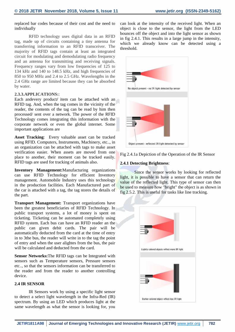
2.4 IR SENSOR
IR Sensors work by using a specific light sensor
to detect a select light wavelength in the Infra-Red (IR)
spectrum. By using an LED which produces light at the
same wavelength as what the sensor is looking for, you
can look at the intensity of the received light. When an
object is close to the sensor, the light from the LED
bounces off the object and into the light sensor as shown
in fig 2.4.1. This results in a large jump in the intensity,
which we already know can be detected using a
threshold.
Fig 2.4.1a Depiction of the Operation of the IR Sensor
2.4.1 Detecting Brightness:
Since the sensor works by looking for reflected
light, it is possible to have a sensor that can return the
value of the reflected light. This type of sensor can then
be used to measure how "bright" the object is as shown in
fig 2.5.2. This is useful for tasks like line tracking.

© 2018 JETIR November 2018, Volume 5, Issue 11 www.jetir.org (ISSN-2349-5162)
JETIR1811A98 Journal of Emerging Technologies and Innovative Research (JETIR) www.jetir.org 783
Fig 2.4.1b Depiction of the Operation of the IR
Sensor to Measure Brightness
2.4.2 FEATURES:
Very low supply current
Photo detector and preamplifier in one package
Internal filter for PCM frequency
Supply voltage: 2.5 V to 5.5 V
Improved immunity against ambient light
Insensitive to supply voltage ripple and noise
Material categorization:
Infrared radiation is the portion of
electromagnetic spectrum having wavelengths longer
than visible light wavelengths, but smaller than
microwaves,
2.5 ARDUINO UNO R3 (Micro controller)
The Arduino Uno is a microcontroller board
based on the ATmega328. It has 14 digital input/output
pins (of which 6 can be used as PWM outputs), 6 analog
inputs, a 16 MHz ceramic resonator, a USB connection, a
power jack, an ICSP header, and a reset button. It
contains everything needed to support the
microcontroller; simply connect it to a computer with a
USB cable or power it with a AC-to-DC adapter or
battery to get started. The Uno differs from all preceding
boards in that it does not use the FTDI USB-to-serial
driver chip. Instead, it features the Atmega16U2
(Atmega8U2 up to version R2) programmed as a USB-
to-serial converter. The Uno board has a resistor pulling
the 8U2 HWB line to ground, making it easier to put into
DFU mode The board has the following new features:
1.0 pinout are to added SDA and SCL pins that
are near to the AREF pin and two other new pins
placed near to the RESET pin, the IOREF that
allow the shields to adapt to the voltage provided
from the board. In future, shields will be
compatible with both the board that uses the
AVR, which operates with 5V and with the
Arduino Due that operates with 3.3V. The
second one is a not connected pin, that is
reserved for future purposes.
Stronger RESET circuit.
Atmega 16U2 replace the 8U2, as shown in fig
2.5.2.
Uno means one in Italian and is named to
mark the upcoming release of Arduino 1.0. The
Uno and version 1.0 will be the reference
versions of Arduino, moving forward. The Uno
is the latest in a series of USB Arduino boards.
Fig 2.5.1 General Diagram of Arduino
Fig 2.5.2 Pin Diagram of Arduino
2.5.1 Description:
Microcontroller ATmega328
Operating Voltage 5V
InputVoltage(recommended) 7-12V
Input Voltage
(limits) 6-20V
Digital I/O Pins 14 (of which 6 provide PWM
output)
Analog Input Pins
6
DC Current per I/O
Pin 40 mA
© 2018 JETIR November 2018, Volume 5, Issue 11 www.jetir.org (ISSN-2349-5162)
JETIR1811A98 Journal of Emerging Technologies and Innovative Research (JETIR) www.jetir.org 784
DC Current for
3.3V Pin 50 mA
Flash Memory 32 KB (ATmega328) of which 0.5
KB used by bootloader
SRAM 2 KB (ATmega328)
EEPROM 1 KB (ATmega328)
Clock Speed 16 MHz
Length 68.6 mm
Width 53.4 mm
Weight 25 g
2.6L293D MOTOR DRIVER
We discuss about L293D motor driver working
for motors. The L293 and L293D are quadruple high-
current half-H drivers. Here we learn about hybrid
bridges (H-BRIDGE). The hi-bridges which are mainly
used in change of polarities. There are two polarities in
every motor. In L293D two h-bridges are present. Four
transistors are present in each h-bridge. If we give logic
bits 1, 0 then current flow is Vcc to motor positive after
that motor positive to negative and then flows to ground.
Then motor rotates in one direction. We change the logic
bits as 0, 1 then current flow is Vcc to motor negative
after that motor negative to positive and then flows to
ground. Then motor rotate in opposite direction. If we
give logic bits 1, 1 then Vcc and ground are short. So
motor does not rotate. If we give logic bits 0, 0 then
motor does not start. Because two pins are given to zero.
The L293 is designed to provide bidirectional
drive currents of up to 1 A at voltages from 4.5 V to 36
V. The L293D is designed to provide bidirectional drive
currents of up to600-mA at voltages from 4.5 V to 36 V.
Both devices are designed to drive inductive loads such
as relays, solenoids, dc and bipolar stepping motors, as
well as other high-current/high-voltage loads in positive-
supply applications. All inputs are TTL compatible. Each
output is a complete totem-
pole drive circuit, with a Darlington transistor
sink and a pseudo-Darlington source. Drivers are enabled
in pairs, with drivers 1 and 2 enabled by 1,2EN and
drivers 3 and 4 enabled by 3,4EN. When an enable input
is high, the associated drivers are enabled and their
outputs are active and in phase with their inputs. When
the enable input is low, those drivers are disabled and
their outputs are off and in the high-impedance state.
With the proper data inputs, each pair of drivers forms a
full-H (or bridge) reversible drive suitable for solenoid or
motor applications.On the L293, external high-speed
output clamp diodes should be used for inductive
transient suppression. A VCC1 terminal, separate from
VCC2, is provided for the logic inputs to minimize
device power dissipation. The L293and L293D is
characterized for operation from 0°C to 70°C.The pin
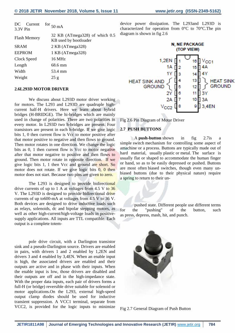
diagram is shown in fig 2.6
Fig 2.6 Pin Diagram of Motar Driver
2.7 PUSH BUTTONS
A push-button shown in fig 2.7is a
simple switch mechanism for controlling some aspect of
amachine or a process. Buttons are typically made out of
hard material, usually plastic or metal. The surface is
usually flat or shaped to accommodate the human finger
or hand, so as to be easily depressed or pushed. Buttons
are most often biased switches, though even many un-
biased buttons (due to their physical nature) require
a spring to return to their un-
pushed state. Different people use different terms
for the "pushing" of the button, such
as press, depress, mash, hit, and punch.
Fig 2.7 General Diagram of Push Button

© 2018 JETIR November 2018, Volume 5, Issue 11 www.jetir.org (ISSN-2349-5162)
JETIR1811A98 Journal of Emerging Technologies and Innovative Research (JETIR) www.jetir.org 785
2.7.1 USES:
The "push-button" has been utilized
in calculators, push-button telephones, kitchen
appliances, and various other mechanical and
electronic devices, home and commercial.
In industrial and commercial applications, push
buttons can be connected together by a
mechanical linkage so that the act of pushing one
button causes the other button to be released. In
this way, a stop button can "force" a start button
to be released. This method of linkage is used in
simple manual operations in which the machine
or process have no electrical circuits for control.
Pushbuttons are often color-coded to associate
them with their function so that the operator will
not push the wrong button in error. Commonly
used colours are red for stopping the machine or
process and green for starting the machine or
process.
Red pushbuttons can also have large heads
(called mushroom heads) for easy operation and
to facilitate the stopping of a machine. These
pushbuttons are called emergency-
-stop buttons and are mandated by the electrical
code in many jurisdictions for increased safety.
This large mushroom shape can also be found in
buttons for use with operators who need to
wear gloves for their work and could not actuate
a regular flush-mounted push button. As an aid
for operators and users in industrial or
commercial applications, a pilot light is
commonly added to draw the attention of the user
and to provide feedback if the button is pushed.
Typically this light is included into the centre of
the pushbutton and a lens replaces the pushbutton
hard centre disk. The source of the energy to
illuminate the light is not directly tied to the
contacts on the back of the pushbutton but to the
action the pushbutton controls. In this way a start
button when pushed will cause the process or
machine operation to be started and a secondary
contact designed into the operation or process
will close to turn on the pilot light and signify the
action of pushing the button caused the resultant
process or action to start.
2.8 DC MOTAR INTERFACING
In this project the d.c motor interfacing consists
of two motors .One motor is used to open & close the car
door and the other is used to move the car forward. This
uses L293D IC interfacing.
2.8.1 PUSH-PULL FOUR CHANNEL DRIVER (load
driver)
Description
Output current is 1A or 600mA per channel
respectively. Each channel is controlled by a TTL-
compatible logic input and each pair of drivers (a The
L293 and L293D are quad push-pull drivers capable of
delivering full bridge) is equipped with an inhibit input
which turns off all four transistors. A separate supply
input is provided for the logic so that it may be run off a
lower voltage to reduce dissipation. Additionally the
L293D includes the output clamping diodes
Within the IC for complete interfacing inductive loads.
Both devices are available in 16-pin Batwing DIP
packages. They are also available in Power S0IC and
Hermetic DIL packages.The general block diagram of
load drive is shown in
Figure 2.8.1: block diagram of load driver L293D
2.8.2 FEATURES:
Output Current 1A Per Channel (600mA for
L293D)
Peak Output Current 2A Per Channel (1.2A for
L293D)
Inhibit Facility
High Noise Immunity
Separate Logic Supply
Over-Temperature Protection

© 2018 JETIR November 2018, Volume 5, Issue 11 www.jetir.org (ISSN-2349-5162)
JETIR1811A98 Journal of Emerging Technologies and Innovative Research (JETIR) www.jetir.org 786
2.9 RFID TECHNOLOGY
Radio-frequency identification (RFID)
uses electromagnetic fields to automatically identify and
track tags attached to objects. The tags contain
electronically stored information. Passive tags collect
energy from a nearby RFID reader's interrogating radio
waves. Active tags have a local power source such as a
battery and may operate at hundreds of meters from the
RFID reader. Unlike a barcode, the tag need not be
within the line of sight of the reader, so it may be
embedded in the tracked object. RFID is one method
for Automatic Identification and Data Capture (AIDC).
RFID tags are used in many industries,
for example, an RFID tag attached to an automobile
during production can be used to track its progress
through the assembly line; RFID-tagged pharmaceuticals
can be tracked through warehouses; and implanting RFID
microchip sin livestock and pets allows positive
identification of animals. Since RFID tags can be
attached to cash, clothing, and possessions, or implanted
in animals and people, the possibility of reading
personally-linked information without consent has raised
serious privacy concerns.[2] These concerns resulted in
standard specifications development addressing privacy
and security issues. ISO/IEC 18000 and ISO/IEC 29167
use on-chip cryptography methods for untraceability, tag
and reader authentication, and over-the-air
privacy. ISO/IEC 20248 specifies a digital signature data
structure for RFID and barcodes providing data, source
and read method authenticity. This work is done
within ISO/IEC JTC 1/SC 31 Automatic identification
and data capture techniques (AIDC).
AUTOMATIC IDENTIFICATION AND DATA
CAPTURE (AIDC):Automatic identification and data
capture (AIDC) refers to the methods of automatically
identifying objects, collecting data about them, and
entering that data directly into computer systems (i.e.
without human involvement). Technologies typically
considered as part of AIDC include bar codes, Radio
Frequency Identification (RFID), biometrics,magnetic
stripes, Optical Character Recognition (OCR), smart
cards, and voice recognition. AIDC is also commonly
referred to as “Automatic Identification,” “Auto-ID,” and
“Automatic Data Capture”
AIDC is the process or means of obtaining
external data, particularly through analysis
of images, sounds or videos. To capture data,
a transducer is employed which converts the actual image
or a sound into a digital file. The file is then stored and at
a later time it can be analysed by a computer, or
compared with other files in a database to verify identity
or to provide authorization to enter a secured system.
Capturing of data can be done in various ways; the best
method depends on application.
AIDC also refers to the methods of recognizing
objects, getting information about them and entering that
data or feeding it directly into computer systems without
any human involvement. Automatic identification and
data capture technologies
include barcodes, RFID, bokodes, OCR, magneticstripes,
smartcards and biometrics (like iris and facial
recognition system).In biometric security systems,
capture is the acquisition of or the process of acquiring
and identifying characteristics such as finger image, palm
image, facial image, iris print or voice print which
involves audio data and the rest all involves video data.
Radio-frequency identification (RFID) is
relatively a new AIDC technology which was first
developed in 1980s. The technology acts as a base in
automated data collection, identification and analysis
systems worldwide. RFID has found its importance in a
wide range of markets including livestock identification
and Automated Vehicle Identification (AVIsystems
because of its capability.
2.10 VOICE MODULE
Today’s consumers demand the best in
audio/voice. They want crystal-clear sound whenever
they are in whatever format they want to use. APLUS
delivers the technology to enhance a listener’ audio/voice
experience
The APR33A3[5]is a powerful audio processor
along with high performance audio analog to digital
converter (ADC) and digital to analog
converter(DAC).The APR33 is a fully integrated solution
offering high performance and unparalleled d integration
with analog input, digital processing and analog output
functionality. The APPR3A incorporates all the
functionality required to perform demanding audio/voice
applications. High quality audio/voice systems with
lower bill of material costs can be can be implemented
with the APR33a3 because of its integrated analog data
converters and full suite of quality enhancing features
such as sample rate converter
The aPR33A series C3.1 is Tape mode manages
messages sequentially much like traditional cassette tape
recorders. Within tape mode two options exist, auto
rewind and non-auto rewind. Auto rewind mode
configures the device to automatically rewind to the
beginning of the message immediately following
recording or playback of the message. In tape mode,
using either option, messages must be recorded or played
back sequentially, much like a traditional cassette tape
© 2018 JETIR November 2018, Volume 5, Issue 11 www.jetir.org (ISSN-2349-5162)
JETIR1811A98 Journal of Emerging Technologies and Innovative Research (JETIR) www.jetir.org 787
recorder specially designed for simple key trigger, user
can record and playback the message. Meanwhile, this
mode provides the power-management system. Users can
let the chip enter power-down mode when unused. It can
effectively reduce electric current consuming to 15uA
and increase the using time in any projects powered by
batteries.
2.10.1 FEATURES:
Operating Voltage Range:3V-6.5V
Single Chip ,high Quality Audio/voice Recording
&Play black solution No External ICs Required
Minimum External Components user Friendly
,Easy to Use Operation
Programming & Development Systems Not
Required
Non-volatile Flash Memory Technology
No Battery Backup Required External Reset Pin.
Low Power Down Current:15micro amp
Resolution Up to 16 –bits
2.10.2 Pin Configuration of IC
Speakers are the final components of the audio
chain—the interface between electrical signals and
sound. With few exceptions, a typical speaker enclosure
contains several transducers that disperse sound into your
living room. The sound seemingly spreads every which
way and may bounce off the walls, carpet, or furniture
several times and to various degrees before it arrives at
your ears. The more I think about this the harder I find it
to understand why this does not result in total sonic
chaos.
To make it easier to understand, I could ignore
the living room for now and look at speakers in an ane-
choic chamber. But since I don't own a speaker lab, I'd
have to drag the speakers out into my back yard, put them
on a high pole, and have them speak towards the sky.
This has a similar benefit as the anechoic chamber in that
hardly any sound bounces off my lawn and none off the
sky. If I looked at the speakers from above, with a micro-
phone attached to an even higher pole, this should give
me almost anechoic results. Unfortunately, living in the
Pacific Northwets [sic], this is not an option either, at
least most of the time.
Enter the computer. My speaker design software
(Lspcad) lets me simulate many of these things. Under-
standing that simulations likely simplify reality, I still
find them very educational. For instance, to simulate the
behaviour of speakers in a room, the software lets me
specify width, length, and height of my living
room, along with the size of the speakers, the transducer
positions on the enclosure, the rates at which my walls,
floor, and ceiling absorb or reflect sound, and the posi-
tion of my ear. Granted, my living room is L-shaped, and
I have two ears, but it's a start, and it is way easier to
change the speaker position in a dialog box than con-
stantly moving around large pieces of furniture.
I still remember the first time I saw the simulated
in-room frequency response curve after entering all the
numbers, particularly my haphazard speaker positioning
choices. These choices can ruin the best speakers, and my
speakers were nowhere nearly the best. I played around
with
SOFTWARE REQUIREMENTS
3.1 Introduction:
http://Arduino.cc/en/Main/Software
Otherwise, the USB stick in your kit2 has the software
under the Software Directory. There are two directories
under that. One is “Windows” and the other is “Mac OS
X”. If you are installing onto Linux, you will need to
follow the directions at ref.[2].
3.1 The Integrated Development Environment (IDE):
You use the Arduino IDE on your computer
(picture following) to create, open, and change sketches
(Arduino calls There are step-by-step directions and the
software available at:programs “sketches”. We will use
the two words interchangeably in this book.). Sketches
define what the board will do. You can either use the
buttons along the top of the IDE or the menu items.
Fig: 3.1 Environment of IDE.
3.1.1 Parts of the IDE: (from left to right, top to
bottom)
1. Compile- Before your program “code” can be
sent to the board, it needs to be converted into
instructions that the board understands. This
process is called compiling.
2. Stop- This stops the compilation process.(I have
never used this button and you probably won’t
have a need to either).
3. Create new Sketch- This opens a new window
to create a new sketch.
4. Open Existing Sketch- This loads a sketch from
a file on your computer.

© 2018 JETIR November 2018, Volume 5, Issue 11 www.jetir.org (ISSN-2349-5162)
JETIR1811A98 Journal of Emerging Technologies and Innovative Research (JETIR) www.jetir.org 788
5. Save Sketch- This saves the changes to the
sketch you are working on.
6. Upload to Board- This compiles and then
transmits over the USB cable to your board.
7. Tab Button- This lets you create multiple files in
your sketch. This is for more advanced
programming.
8. Sketch Editor- This is where you write or edit
sketches.
9. Text Console- This shows you what the IDE is
currently doing and is also where error messages
display if you make a mistake in typing your
program (often called a syntax error).
10. Line Number- This shows you what line number
your cursor is on. It is useful since the compiler
gives error messages with a line number.
3.2 Features of Arduino Programming:
Easy-to-use.
Full Arduino™ compatible
Supported file formats and programming
languages: Arduino, C, C++, Header, HTML,
HTML5, JavaScript, CSS, Text
IDE languages (English, German)
Supports all Arduino libraries.
Object & Function Explorer.
Code Autocompletion.
Code Folding.
Bookmarks.
Hints & Information about the Arduino
commands.
Advanced Reference Search Function (File
Cross-Search)
Website editor for IoT applications with
Arduino.
Comfortable and powerful code editor.
Export function to Arduino IDE (good way for
older Arduino versions less 1.6.x)
Manage full project without project files in one
editor
Value Converter (DEC, HEX, BIN, ASCII)
WORKING OF THE MODEL
4.1 VIP MODULE:
Theblindpeople section
consistsofRFIDreader,AT89C51microcontroller,
power supply ,voice synthesizer, headset, RF
transmitter as shown in fig. The 5V dc is given to
operate the microcontroller.When the tag is
interpreted or decoded, the sequence is displayed as
numbers unique to the tag. Since it make use of the
Radio frequency interference technique, Radio
frequency helps in decoding the information. The
radio frequency used to decode the data in the
RFID tag is produced by the RFID reader.The RFID
reader obtains the address of the desired RFID
tag(the address differs from each tag) the identified
tag when attached to the bus will be the reference to
that bus and is indirectly detected . Then the RS 232
is used to transmit the serial information to the
microcontroller and it is designed to provide a voice
based announcement for the user.So that the user gets
the voice which pronounces the destination
location.APR9600 device offers true single chip
voice recording, non-volatile
storage and play back capability for 40-60 seconds.
Then the information in the voice IC is heard in the
speaker.

© 2018 JETIR November 2018, Volume 5, Issue 11 www.jetir.org (ISSN-2349-5162)
JETIR1811A98 Journal of Emerging Technologies and Innovative Research (JETIR) www.jetir.org 789
4.2 BUS MODULE:
The bus section consist of RFID tag,RF receiver,
buzzer and battery as shown in fig. The first step of
application is to intimate the bus driver about the bus
stop, so that the driver can provide the special attention at
VIP Person is boarding bus.By using wireless
communication of transmitters and receivers nature of
RF protocols using TWS 434 and RWS 434. The TWS-
434 transmitter accepts both linear and digital inputs can
operate from 1.5 to 12 Volts-DC. The P2_0, P2_1,
P2_2and P2_3 pin of controller is assumed as data
transmit pins. The DATA_OUT pin of encoder is
connected to the DATA_IN pinof RF Transmitter and
then the RF Transmitter transmits the data to the receiver.
The RWS 434receiver operates from 4.5 to 5.5 volts-DC
and has both linear and digital out puts. The P2_0, P2_1,
P2_2 and P2_3 pin of controller is assumed as data
transmit pins. The DATA_OUT pin of RF Transmitter is
connected to the DATA_IN pin of DECODER and then
the data is processed by the decoder.The receiver which
has the 12Vbattery receives the radio wave from the
transmitter which activates the buzzer. The buzzer
isussed to indicate the presence of VIP person to the
driver
CONCLUSION:
Since the estimated number of blind people over the
world is between 40 to 45 million, special services
should be provided to them in order to give them the
right to live as others do. In this paper, we presented a
bus detection system for blind people using RFID. The
proposed system is easy and provides a convenient
service for all the passengers; not only the blind ones.
The system has two subsystems which are: the bus
subsystem and the station subsystem. Bus subsystem
announces the coming stations in the bus route for all
passengers. 50 Moreover, the bus driver will be provided
with the number of blind people who required the bus
and their destinations. The station sub-system will give
announcement of the approaching buses. A prototype of
the proposed system was successfully built and tested.
Our design is promising in terms of its performance and
functionality.
FUTURE SCOPE:
This prototype to assist the Visionless people while
boarding the bus has wide applications other than just
helping the blind people inform their presence to the
bus driver. In further stages of development this project
can be used to enhance the safety and comfort of a
© 2018 JETIR November 2018, Volume 5, Issue 11 www.jetir.org (ISSN-2349-5162)
JETIR1811A98 Journal of Emerging Technologies and Innovative Research (JETIR) www.jetir.org 790
larger section of society. Following are some of the
anticipated future scopes: 1. This system can be installed
over the taxies and not just public buses, all over the city
so that people can very easily communicate with them.
2. This system, if manufactured commercially, is very
economic and thus can be made available at the stores
so that women, children, senior citizens or any section of
society can use it. 3. With few changes in the hardware
and programming, this prototype can be turned into a
security device. Women may have this all the time with
them while they are out of their homes. Each policeman
will also be handed over one device. So whenever any
woman feels any kind of danger,
REFERENCE
1 New York Transportation Statistics. Available from:
http://transportation-
modescity.findthedata.org/q/1447/1033/Howmany-
people-use-public-transportation-to-commute-inNew-
YorkNew-York. Accessed 25 November 2015.
2 Hersh, M.A., Johnson, M.A. Assistive Technology for
Visually Impaired and Blind People, Springer, 2008. 51
3 Miesenberger, K. [et al.] [eds.] Computers Helping
People with Special Needs, LNCS, vol. 4061 Springer
Berlin / Heidelberg, 10th International Conference,
ICCHP 2006, Linz, Austria, July 11-13, 2006.
4 Implementation of RFID for blind bus boarding system
B.N Kiran, Smitha B.C, Sushma K.N, Varsha
R.Gowda,”International Journal of Science Engineering
and Applied Science(IJSEAS)-Volume 1.
5 Myat K Khine, Thiri Thandar Aung,”RFID- based Audio
Guidance Cane For Blind and Visually Impaired Person,
International Journal of Engineering Research &
Technology(IJERT), Vol. 3 Issue 8, August -2014.
6 Quoc T., Kim M., Lee H. and Eom k., “Wireless Sensor
Network apply for the Blind U-bus System,”
International Journal of u- and eService, Science and
Technology Vol. 3, No. 3, September, 2010.
7 On The Bus Public Transport. Available at:
http://www.onthebusproject.com, Accessed 25
November 2015.