Embed Size (px)
Citation preview
Universal Field I/O eFD-75
CompanyInformation
SystemsOverview
ProgrammableControllers
Field I/O
Software
C-more & other HMI
Drives
SoftStarters
Motors &Gearbox
Steppers/Servos
Motor Controls
ProximitySensors
Photo Sensors
Limit Switches
Encoders
CurrentSensors
PressureSensors
TemperatureSensors
Pushbuttons/Lights
Process
Relays/Timers
Comm.
TerminalBlocks & Wiring
Power
CircuitProtection
Enclosures
Tools
Pneumatics
Safety
Appendix
ProductIndex
Part #Index
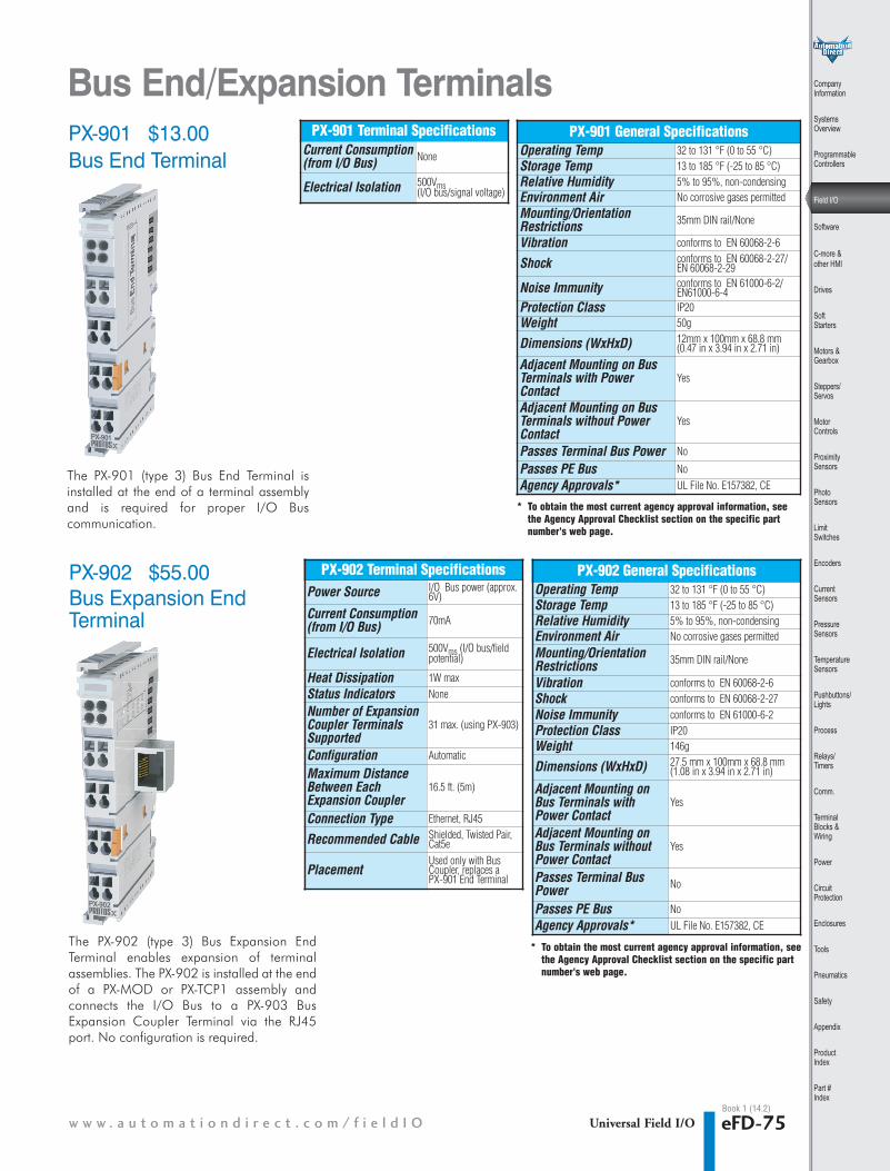
Bus End/Expansion TerminalsPX-901 $13.00
PX-902 $55.00
Bus End Terminal
The PX-901 (type 3) Bus End Terminal isinstalled at the end of a terminal assemblyand is required for proper I/O Bus communication.
The PX-902 (type 3) Bus Expansion EndTerminal enables expansion of terminalassemblies. The PX-902 is installed at the endof a PX-MOD or PX-TCP1 assembly andconnects the I/O Bus to a PX-903 BusExpansion Coupler Terminal via the RJ45port. No configuration is required.
PX-901
PX-901
PX-902 Terminal SpecificationsPower Source I/O Bus power (approx.
6V)
Current Consumption (from I/O Bus) 70mA
Electrical Isolation 500Vms (I/O bus/fieldpotential)
Heat Dissipation 1W maxStatus Indicators None
Number of ExpansionCoupler TerminalsSupported
31 max. (using PX-903)
Configuration Automatic
Maximum DistanceBetween EachExpansion Coupler
16.5 ft. (5m)
Connection Type Ethernet, RJ45
Recommended Cable Shielded, Twisted Pair,Cat5e
PlacementUsed only with BusCoupler, replaces a PX-901 End Terminal
PX-902 General SpecificationsOperating Temp 32 to 131 °F (0 to 55 °C)Storage Temp 13 to 185 °F (-25 to 85 °C)Relative Humidity 5% to 95%, non-condensingEnvironment Air No corrosive gases permitted
Mounting/OrientationRestrictions 35mm DIN rail/None
Vibration conforms to EN 60068-2-6Shock conforms to EN 60068-2-27Noise Immunity conforms to EN 61000-6-2Protection Class IP20Weight 146g
Dimensions (WxHxD) 27.5 mm x 100mm x 68.8 mm(1.08 in x 3.94 in x 2.71 in)
Adjacent Mounting onBus Terminals withPower Contact
Yes
Adjacent Mounting onBus Terminals withoutPower Contact
Yes
Passes Terminal BusPower No
Passes PE Bus NoAgency Approvals* UL File No. E157382, CE
Book 1 (14.2)
PX-901 Terminal SpecificationsCurrent Consumption (from I/O Bus) None
Electrical Isolation 500Vms(I/O bus/signal voltage)
PX-901 General SpecificationsOperating Temp 32 to 131 °F (0 to 55 °C)Storage Temp 13 to 185 °F (-25 to 85 °C)Relative Humidity 5% to 95%, non-condensingEnvironment Air No corrosive gases permittedMounting/OrientationRestrictions 35mm DIN rail/None
Vibration conforms to EN 60068-2-6
Shock conforms to EN 60068-2-27/EN 60068-2-29
Noise Immunity conforms to EN 61000-6-2/ EN61000-6-4
Protection Class IP20Weight 50g
Dimensions (WxHxD) 12mm x 100mm x 68.8 mm(0.47 in x 3.94 in x 2.71 in)
Adjacent Mounting on BusTerminals with PowerContact
Yes
Adjacent Mounting on BusTerminals without PowerContact
Yes
Passes Terminal Bus Power No
Passes PE Bus NoAgency Approvals* UL File No. E157382, CE
Bus Expansion EndTerminal
PX-902
PX-902
* To obtain the most current agency approval information, seethe Agency Approval Checklist section on the specific partnumber's web page.
* To obtain the most current agency approval information, seethe Agency Approval Checklist section on the specific partnumber's web page.
w w w . a u t o m a t i o n d i r e c t . c o m / f i e l d I O
1 - 8 0 0 - 6 3 3 - 0 4 0 5eFD-76 Universal Field I/O
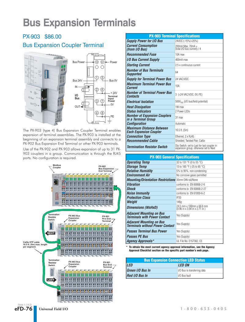
Bus Expansion TerminalsPX-903 $86.00Bus Expansion Coupler Terminal
PX-903
1 5
2 6
3 7
4 9
The PX-903 (type 4) Bus Expansion Coupler Terminal enablesexpansion of terminal assemblies. The PX-903 is installed at thebeginning of an expansion terminal assembly and connects to aPX-902 Bus Expansion End Terminal or other PX-903 terminals.
Use of the PX-902 and PX-903 allows expansion of up to 31 PX-903 couplers in a group. Communication is through the RJ45ports. No configuration is required.
TerminalInputPower
Power
1
2
3
4
5
6
7
8
+ 24V
0V
PE
Bus 0VBus 24V
I/OBus
IN
OUT
Bus Power
PX-903 Terminal SpecificationsSupply Power for I/O Bus 24VDC (-15%/+20%)
Current Consumption (from I/O Bus)
200mA Max, 70mA + (total I/O bus current) / 4
Recommended Fuse 10A max
I/O Bus Current Supply 400mA max
Starting Current 2.5 x continuous current
Number of Bus TerminalsSupported 64
Supply for Terminal Power Bus 24 VAC/VDC
Maximum Terminal Power BusCurrent 10A
Number of Terminal Power BusContacts 3 (+24 VAC/VDC, 0V, PE)
Electrical Isolation 500Vms (I/O bus/field potential)
Heat Dissipation 1W maxStatus Indicators 2 Power LEDsNumber of Expansion Couplersin a Terminal Group 31 max
Configuration Automatic
Maximum Distance BetweenEach Expansion Coupler 16.5 ft. (5m)
Connection Type Ethernet, 2 x RJ45Recommended Cable Shielded, Twisted Pair, Cat5e
Termination Resistor Switch Dip Switch, set to Last for last coupler inexpansion group, otherwise set to Next
PX-903 General SpecificationsOperating Temp 32 to 131 °F (0 to 55 °C)Storage Temp 13 to 185 °F (-25 to 85 °C)Relative Humidity 5% to 95%, non-condensingEnvironment Air No corrosive gases permitted
Mounting/Orientation Restrictions 35mm DIN rail/None
Vibration conforms to EN 60068-2-6Shock conforms to EN 60068-2-27Noise Immunity conforms to EN 61000-6-2Protection Class IP20Weight 146g
Dimensions (WxHxD) 24.5 mm x 100mm x 68.8 mm(0.96 in x 3.94 in x 2.71 in )
Adjacent Mounting on BusTerminals with Power Contact Yes (Supply)
Adjacent Mounting on BusTerminals without Power Contact Yes (Supply)
Passes Terminal Bus Power Yes (Supply)
Passes PE Bus Yes (Supply)Agency Approvals* UL File No. E157382, CE
* To obtain the most current agency approval information, see the AgencyApproval Checklist section on the specific part number's web page.
Bus Expansion Connection LED StatusLED LED ONGreen I/O Bus In I/O Bus is transferring data
Red I/O Bus In I/O Bus fault
1
2
3
4
5
6
7
8
PX-903
1
2
3
4
5
6
7
8
PX-14444
1
2
3
4
5
6
7
8
PX-14444
1
2
3
4
5
6
7
8
PX-14444
1
2
3
4
5
6
7
8
PX-14444
1
2
3
4
5
6
7
8
PX-14444
1
2
3
4
5
6
7
8
PX-14444
1
2
3
4
5
6
7
8
PX-14444
1
2
3
4
5
6
7
8
PX-14444
1
2
3
4
5
6
7
8
PX-14444
1
2
3
4
5
6
7
8
PX-144
1
2
3
4
5
6
7
8
PX-144
1
2
3
4
5
6
7
8
PX-901PX-1444
8
PX 1444444 PX-144444 PPXPXP -X-X 90144
44 8
PX 1444
44444 888
PPPXXPPXPP 901901
1
2
3
4
5
6
7
8444444 88
PX-903
1
2
3
4
5
6
7
8
PX-14444
1
2
3
4
5
6
7
8
PX-14444
1
2
3
4
5
6
7
8
PX-14444
1
2
3
4
5
6
7
8
PX-14444
1
2
3
4
5
6
7
8
PX-14444
1
2
3
4
5
6
7
8
PX-14444
1
2
3
4
5
6
7
8
PX-14444
1
2
3
4
5
6
7
8
PX-14444
1
2
3
4
5
6
7
8
PX-14444
1
2
3
4
5
6
7
8
PX-144
1
2
3
4
5
6
7
8
PX-144
1
2
3
4
5
6
7
8
PX-901
5 11 5 1111111 5555
6 22 6 222222 666
PX-1444
8
PX 144
7
4444 PX-144444 PPXPXP -X-X 90144
44 8
PX 1444
44444 888
PPPXXPPXPP 901901
33 7 33333333 7777
1
2
3
4
5
6
7
8
PX-144
1
2
3
4
5
6
7
8
PX-144
1
2
3
4
5
6
7
8
PX-144
1
2
3
4
5
6
7
8
PX-144
1
2
3
4
5
6
7
8
PX-144
1
2
3
4
5
6
7
8
PX-144
1
2
3
4
5
6
7
8
PX-144
1
2
3
4
5
6
7
8
PX-144
1
2
3
4
5
6
7
8
PX-144
1
2
3
4
5
6
7
8
PX-144
1
2
3
4
5
6
7
8
PX-144
PX-902Bus ExpansionEnd Terminal
Modbus Coupler
PX-901Bus End Terminal
PX-903 BusExpansion Coupler
PX-901Bus End Terminal
TerminationResistorSwitch
TerminationResistorSwitch
PX-903 BusExpansion Coupler
PX-902
d TerminalTeTeTerminalTerminalTeTerminalTerminalTerminal
PX-TCP1
TM
1234
Us GNDs
Up
GNDp
.PE
1234
+ +
PEPE
ONDIP
1 2
3 4
5 6
7 8
ON1 2
3333333 77 3
444444 88
PXPXP -X-X 903
4
PX
Terminatiioon
22222222 66
555555 1
2
5
6
7
11
22
33
555
6
7
111
222
333
5
6
7
11
22
33
5
6
7
11
22
33
5
6
7
11
22
33
5
6
7
11
22
33
5
6
7
11
22
33
5
6
7
11
22
33
5
6
7
11
22
33
5 11 5 111111 5555
6 22 6 222222 666
7 33 7 33333333 7777
PX-901Bus End TerminalTerminalTeTeTerminalTerminalTeTerminalTerminal
PX-903 BusExpansion CouplerCoCoCoCoCoCoCoCo
1
22222222 66
555555
Termination
1
2
3
4
5
6
7
8
PX-144444
11
22
33
44
5
6
7
8
PX-144444
11
22
33
44
5
6
7
8
PX-144444
11
22
33
44
5
6
7
8
PX-144444
11
22
33
44
5
6
7
8
PX-144444
11
22
33
44
5
6
7
8
PX-144444
11
22
33
44
5
6
7
8
PX-144444
11
22
33
44
5
6
7
8
PX-144444
11
22
33
44
5
6
7
8
PX-144444
11
22
33
44
PX
5
6 222 6
PX-14
8
PX-14
7
4444 PXPX-144444 PPXPXP -X-X 90244
4444
PX
4 8
PX-1444 PPPPXXPPXPP 902902
3333 7
1111 55
3
PX-TCP1P1P1
TM
Up
GNDp
.PE
Us GNDs
+ +
PEPEPE
ONONONDIPDIPDIP
1 2
3 4
5 6
7 8
ONONON1 2
3333333 77 3
22222 66
11111111111111
TerminationResistorResistorSSwwiittcchh
Terminationionon
11111111111111
ResistorResistorSwitch
Cat5e STP cable16.5 ft. (5m) max. lengthper segment
LAST
NEXT
Book 1 (14.2)
1 - 8 0 0 - 6 3 3 - 0 4 0 5eFD-72 Universal Field I/OBook 1 (14.2)
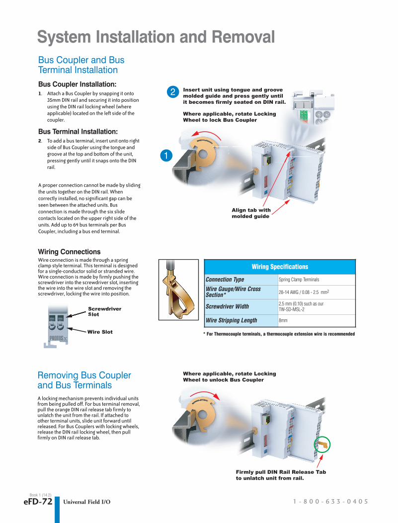
System Installation and Removal
Removing Bus Couplerand Bus TerminalsA locking mechanism prevents individual unitsfrom being pulled off. For bus terminal removal,pull the orange DIN rail release tab firmly tounlatch the unit from the rail. If attached toother terminal units, slide unit forward untilreleased. For Bus Couplers with locking wheels,release the DIN rail locking wheel, then pullfirmly on DIN rail release tab.
Bus Coupler and BusTerminal InstallationBus Coupler Installation:1. Attach a Bus Coupler by snapping it onto
35mm DIN rail and securing it into positionusing the DIN rail locking wheel (whereapplicable) located on the left side of thecoupler.
Bus Terminal Installation:2. To add a bus terminal, insert unit onto right
side of Bus Coupler using the tongue andgroove at the top and bottom of the unit,pressing gently until it snaps onto the DINrail.
A proper connection cannot be made by slidingthe units together on the DIN rail. When correctly installed, no significant gap can beseen between the attached units. Bus connection is made through the six slide contacts located on the upper right side of theunits. Add up to 64 bus terminals per Bus Coupler, including a bus end terminal.
Insert unit using tongue and groove molded guide and press gently until it becomes firmly seated on DIN rail.
Align tab with molded guide
ntil raaiill.
Where applicable, rotate Locking Wheel to lock Bus Coupler
2
1
Wiring Specifications
Connection Type Spring Clamp Terminals
Wire Gauge/Wire CrossSection* 28-14 AWG / 0.08 - 2.5 mm2
Screwdriver Width 2.5 mm (0.10) such as ourTW-SD-MSL-2
Wire Stripping Length 8mm
Wiring ConnectionsWire connection is made through a springclamp style terminal. This terminal is designedfor a single-conductor solid or stranded wire.Wire connection is made by firmly pushing thescrewdriver into the screwdriver slot, insertingthe wire into the wire slot and removing thescrewdriver, locking the wire into position.
Firmly pull DIN Rail Release Tabto unlatch unit from rail.
Where applicable, rotate Locking Wheel to unlock Bus Coupler
* For Thermocouple terminals, a thermocouple extension wire is recommendedWire Slot
ScrewdriverSlotScSl
w w w . a u t o m a t i o n d i r e c t . c o m / f i e l d I O Universal Field I/O eFD-73
CompanyInformation
SystemsOverview
ProgrammableControllers
Field I/O
Software
C-more & other HMI
Drives
SoftStarters
Motors &Gearbox
Steppers/Servos
Motor Controls
ProximitySensors
Photo Sensors
Limit Switches
Encoders
CurrentSensors
PressureSensors
TemperatureSensors
Pushbuttons/Lights
Process
Relays/Timers
Comm.
TerminalBlocks & Wiring
Power
CircuitProtection
Enclosures
Tools
Pneumatics
Safety
Appendix
ProductIndex
Part #Index
Book 1 (14.2)
PX-TCP2 PX-903 PX-902StandardTerminal
PX-TCP1 / PX-MOD
100 mm[3.94”]
68.8 mm[2.71”]
100 mm[3.94”]
51 mm[2.01”]
PX-TCP2
mm4”]
51 mm
EthernetTCP/IP
COM
ERROR
WDG
I/O RUN
I/O ERR
PX-TCP2TM
ON 1 2
3 4
5 6
7 8
9 10
m]
m
PX-TCP2TM
24V 0V
+ +
PEPE
EthernetTCP/IPTCP/IPTCP/IP
COM
I/O I/O ERR+I/O I/O RUN +
ERROR 24VWDG
44 mm[1.73”]
0V
+
PE
0V24V
44 m
PX-TCP1
TM
mm3”]
mm
1234
Us GNDs
Up
GNDp
.PE
PXPX-MODPX-MODPXPXPX-MOD-MODPXPXPX-MPX-MPX-MODPX-MOD
1234
24V 0V
+ +
PEPE
ONDIP
1 2 3 4 5 6 7 8
ON1 2
24.5 mm[.96”]
mm
PX-TCP1CP1PX-TCP1
TM
Up
GNDp
.PE
Us GNDsUs GNDsUs GNDsGNDs
1234
24V 0V
+ +
PEPE
[.96”]24.5 mm
[.96”]24.5 mm
1
2
3
4
5
6
7
84 8
+
PE
3 7
2 662
PX-903
PX-903
1 51 51 51 5
27.5 mm[.96”][.96”][.96”]
PX-902
27.5 mm
PPPXXXPXPPPXP -X-X 902902902902902902
12 mm[.47”]
1
2
3
4
5
6
7
8
33
4
6
77
8
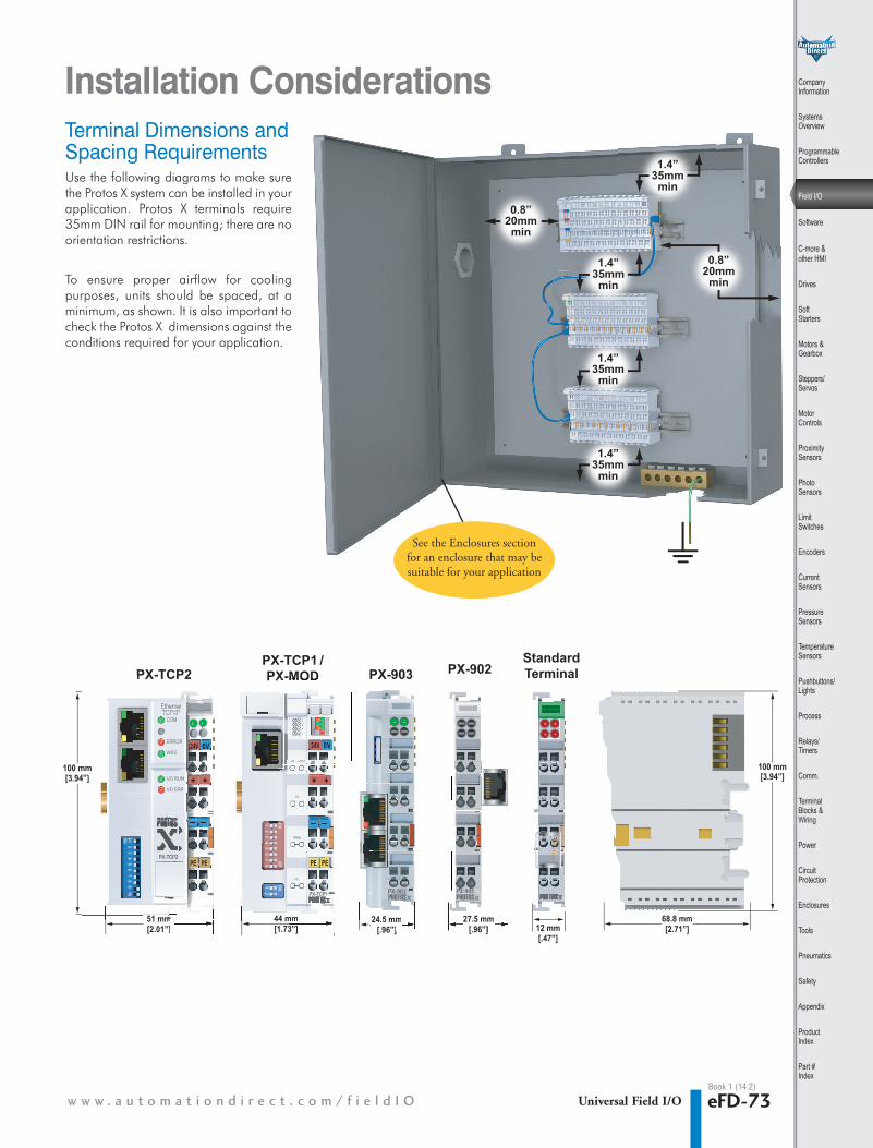
1.4”35mmmin
1.4”35mmmin
1.4”35mmmin
1.4”35mmmin
0.8”20mmmin
0.8”20mmmin
Installation ConsiderationsTerminal Dimensions andSpacing RequirementsUse the following diagrams to make surethe Protos X system can be installed in your application. Protos X terminals require35mm DIN rail for mounting; there are noorientation restrictions.
To ensure proper airflow for coolingpurposes, units should be spaced, at aminimum, as shown. It is also important tocheck the Protos X dimensions against theconditions required for your application.
See the Enclosures sectionfor an enclosure that may besuitable for your application
1 - 8 0 0 - 6 3 3 - 0 4 0 5eFD-74 Universal Field I/OBook 1 (14.2)
I/O Bus contacts
1
2
3
4
5
6
7
8
PX-970
Note, buscontacts donot exist on
this module
1
2
3
4
5
6
7
8
2 6
3 7
I/O Bus contacts
I/O Bus contacts
1
2
3
4
5
6
7
8
2 6
3 73 7
4 8
Terminalpower
buscontact
Terminalpower
buscontact
TerminalPE
buscontact
Terminal powerbus pass thorugh
Terminal powerbus pass thorugh
Terminal PEbus pass thorugh
Terminal powerbus supply
Terminal powerbus supply
Terminal powerbus supply
Note, bus and pass throughcontactsdo not exist on this module
Note, bus and pass throughcontactsdo not exist on this module
I/O Bus contacts
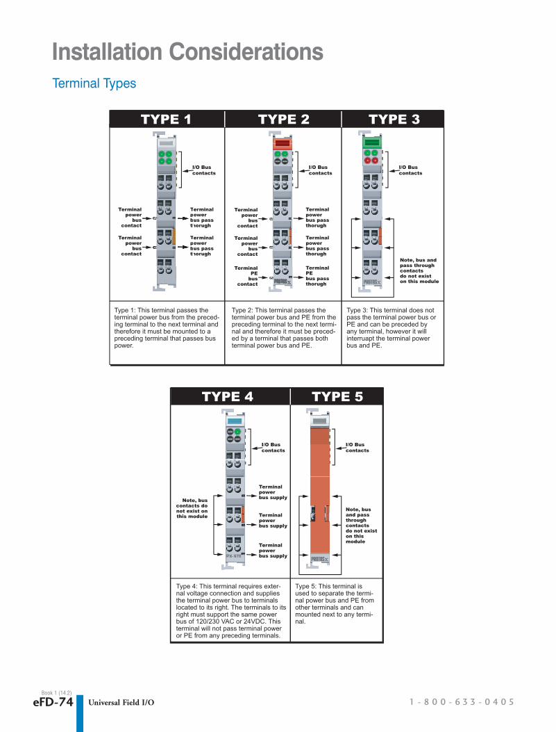
Protos XTM Five Basic Terminal Types
Type 1: This terminal passes the terminal power bus from the preced-ing terminal to the next terminal and therefore it must be mounted to a preceding terminal that passes bus power.
TYPE 1 TYPE 2 TYPE 3 TYPE 4 TYPE 5
Type 2: This terminal passes the terminal power bus and PE from the preceding terminal to the next termi-nal and therefore it must be preced-ed by a terminal that passes both terminal power bus and PE.
Type 3: This terminal does not pass the terminal power bus or PE and can be preceded by any terminal, however it will interruapt the terminal power bus and PE.
Type 4: This terminal requires exter-nal voltage connection and supplies the terminal power bus to terminals located to its right. The terminals to its right must support the same power bus of 120/230 VAC or 24VDC. This terminal will not pass terminal power or PE from any preceding terminals.
Type 5: This terminal is used to separate the termi-nal power bus and PE from other terminals and can mounted next to any termi-nal.
Protos XTM is a trademark of Automationdirect.com Incorporated
Terminalpower
buscontact
Terminal powerbus pass thorugh
Terminalpower
buscontact
Terminal powerbus pass thorugh
I/O Bus contacts
1
2
3
4
5
6
7
8
Tepobuth
Tepobuth
2 6
Tepobuth
TeTepobuth
3 7 TeTe
Terminal Types
I/O Bus contacts
1
2
3
4
5
6
7
8
PX-970
2 6
33 77
4 8
PXPXP -XX 970
Note, buscontacts donot exist on
this module
1
2
3
4
5
6
7
8
I/O Bus contacts
I/O Bus contacts
1
2
3
4
5
6
7
8
Terminalpower
buscontact
Terminalpower
buscontact
TerminalPE
buscontact
Terminal powerbus pass thorugh
Terminal powerbus pass thorugh
Terminal PEbus pass thorugh
Terminal powerbus supply
Terminal powerbus supply
Terminal powerbus supply
Note, bus and pass throughcontactsdo not exist on this module
Note, bus and pass throughcontactsdo not exist on this module
I/O Bus contacts
Protos XTM Five Basic Terminal Types
Type 1: This terminal passes the terminal power bus from the preced-ing terminal to the next terminal and therefore it must be mounted to a preceding terminal that passes bus power.
TYPE 1 TYPE 2 TYPE 3 TYPE 4 TYPE 5
Type 2: This terminal passes the terminal power bus and PE from the preceding terminal to the next termi-nal and therefore it must be preced-ed by a terminal that passes both terminal power bus and PE.
Type 3: This terminal does not pass the terminal power bus or PE and can be preceded by any terminal, however it will interruapt the terminal power bus and PE.
Type 4: This terminal requires exter-nal voltage connection and supplies the terminal power bus to terminals located to its right. The terminals to its right must support the same power bus of 120/230 VAC or 24VDC. This terminal will not pass terminal power or PE from any preceding terminals.
Type 5: This terminal is used to separate the termi-nal power bus and PE from other terminals and can mounted next to any termi-nal.
Protos XTM is a trademark of Automationdirect.com Incorporated
Terminalpower
buscontact
Terminal powerbus pass thorugh
Terminalpower
buscontact
Terminal powerbus pass thorugh
I/O Bus contacts
1
2
3
4
5
6
7
8
Installation Considerations