Embed Size (px)
Citation preview

Relion® 670 series
Busbar protection REB670Pre-configuredProduct Guide

Contents
1. Application.....................................................................3
2. Available functions..........................................................9
3. Differential protection....................................................12
4. Zone selection..............................................................13
5. Current protection........................................................16
6. Control.........................................................................16
7. Logic............................................................................17
8. Monitoring....................................................................17
9. Basic IED functions......................................................19
10. Human machine interface............................................19
11. Station communication ...............................................20
12. Remote communication..............................................21
13. Hardware description..................................................21
14. Connection diagrams..................................................24
15. Technical data.............................................................30
16. Ordering......................................................................54
Disclaimer
The information in this document is subject to change without notice and should not be construed as a commitment by ABB. ABB assumes no responsibility for any
errors that may appear in this document.
© Copyright 2012 ABB.
All rights reserved.
Trademarks
ABB and Relion are registered trademarks of the ABB Group. All other brand or product names mentioned in this document may be trademarks or registered
trademarks of their respective holders.
Busbar protection REB670 1MRK505212-BEN EPre-configured Product version: 1.2
2 ABB

1. ApplicationREB670 is designed for the selective, reliable and fastdifferential protection of busbars, T-connections and meshedcorners. REB670 can be used for protection of single anddouble busbar with or without transfer bus, double circuitbreaker or one-and-half circuit breaker stations. The IED isapplicable for the protection of medium voltage (MV), highvoltage (HV) and extra high voltage (EHV) installations at apower system frequency of 50Hz or 60Hz. The IED candetect all types of internal phase-to-phase and phase-to-earth faults in solidly earthed or low impedance earthedpower systems, as well as all internal multi-phase faults inisolated or high-impedance earthed power systems.
REB670 has very low requirements on the main currenttransformers (that is, CTs) and no interposing currenttransformers are necessary. For all applications, it is possibleto include and mix main CTs with 1A and 5A rated secondarycurrent within the same protection zone. Typically, CTs withup to 10:1 ratio difference can be used within the samedifferential protection zone. Adjustment for different main CTratios is achieved numerically by a parameter setting.
The numerical, low-impedance differential protection functionis designed for fast and selective protection for faults withinprotected zone. All connected CT inputs are provided with arestraint feature. The minimum pick-up value for thedifferential current is set to give a suitable sensitivity for allinternal faults. For busbar protection applications typical
setting value for the minimum differential operating current isfrom 50% to 150% of the biggest CT. This setting is madedirectly in primary amperes. The operating slope for thedifferential operating characteristic is fixed to 53% in thealgorithm.
The fast tripping time of the low-impedance differentialprotection function is especially advantageous for powersystem networks with high fault levels or where fast faultclearance is required for power system stability.
The advanced open CT detection algorithm detects instantlythe open CT secondary circuits and prevents differentialprotection operation without any need for additional checkzone.
Differential protection zones in REB670 include a sensitiveoperational level. This sensitive operational level is designedto be able to detect internal busbar earth faults in lowimpedance earthed power systems (that is, power systemswhere the earth-fault current is limited to a certain level,typically between 300A and 2000A primary by a neutral pointreactor or resistor). Alternatively this sensitive level can beused when high sensitivity is required from busbar differentialprotection (that is, energizing of the bus via long line).
Overall operating characteristic of the differential function inREB670 is shown in figure 1.
Differential protectionoperation characteristic
Operateregion
Diff Oper Level
I d [P
rimar
y Am
ps]
Iin [Primary Amps]
s=0.53
I d=I in
Sensitivedifferentialprotection
en06000142.vsd
Sensitive Oper Level Sens Iin Block
IEC06000142 V1 EN
Figure 1. REB670 operating characteristic
Integrated overall check zone feature, independent from anydisconnector position, is available. It can be used in doublebusbar stations to secure stability of the busbar differential
protection in case of entirely wrong status indication ofbusbar disconnector in any of the feeder bays.
Busbar protection REB670 1MRK505212-BEN EPre-configured Product version: 1.2 Issued: February 2015
Revision: E
ABB 3

Flexible, software based dynamic Zone Selection enableseasy and fast adaptation to the most common substationarrangements such as single busbar with or without transferbus, double busbar with or without transfer bus, one-and-a-half breaker stations, double busbar-double breaker stations,ring busbars, and so on. The software based dynamic ZoneSelections ensures:
• Dynamic linking of measured CT currents to theappropriate differential protection zone as required bysubstation topology
• Efficient merging of the two differential zones whenrequired by substation topology (that is load-transfer)
• Selective operation of busbar differential protectionensures tripping only of circuit breakers connected tothe faulty zone
• Correct marshaling of backup-trip commands frominternally integrated or external circuit breaker failureprotections to all surrounding circuit breakers
• Easy incorporation of bus-section and/or bus-couplerbays (that is, tie-breakers) with one or two sets of CTsinto the protection scheme
• Disconnector and/or circuit breaker status supervision
Advanced Zone Selection logic accompanied by optionallyavailable end-fault and/or circuit breaker failure protectionsensure minimum possible tripping time and selectivity forfaults within the blind spot or the end zone between bay CTand bay circuit breaker. Therefore REB670 offers bestpossible coverage for such faults in feeder and bus-section/bus-coupler bays.
Optionally available circuit breaker failure protection, one forevery CT input into REB670, offers secure local back-upprotection for the circuit breakers in the station.
Optionally available four-stage, non-directional overcurrentprotections, one for every CT input into REB670, provideremote backup functionality for connected feeders andremote-end stations.
It is normal practice to have just one busbar protection IEDper busbar. Nevertheless some utilities do apply twoindependent busbar protection IEDs per zone of protection.REB670 IED fits both solutions.
A simplified bus differential protection for multi-phase faultsand earth faults can be obtained by using a single, one-phaseREB670 IED with external auxiliary summation currenttransformers.
The wide application flexibility makes this product anexcellent choice for both new installations and therefurbishment of existing installations.
Description of 3 ph package A20Three-phase version of the IED with two low-impedancedifferential protection zones and four three-phase CT inputs
A20. The version is intended for simpler applications such asT-connections, meshed corners, and so on.
Description of 3 ph package A31Three-phase version of the IED with two low-impedancedifferential protection zones and eight three-phase CT inputsA31. The version is intended for applications on smallerbusbars, with up to two zones and eight CT inputs.
Description of 1 ph packages B20 and B21One-phase version of the IED with two low-impedancedifferential protection zones and twelve CT inputs B20, B21.
• Due to three available binary input modules, the B20 isintended for applications without need for dynamic ZoneSelection such as substations with single busbar with orwithout bus-section breaker, one-and-half breaker ordouble breaker arrangements. Three such IEDs offercost effective solutions for such simple substationarrangements with up to twelve CT inputs.
• The B21 is intended for applications in substationswhere dynamic Zone Selection or bigger number ofbinary inputs and outputs is needed. Such stations forexample are double busbar station with or withouttransfer bus with up to 12 CT inputs. Note that binaryinputs can be shared between phases by including theLDCM communication module. This simplifies panelwiring and saves IO boards.
• This version can be used with external auxiliary 3-phaseto 1-phase summation current transformers withdifferent turns ratio for each phase.
Description of 1 ph package B31One-phase version of the IED with two low-impedancedifferential protection zones and twenty-four CT inputs B31.
• The IED is intended for busbar protection applications inbig substations where dynamic Zone Selection, quitelarge number of binary inputs and outputs and many CTinputs are needed. The IED includes two differentialzones and twenty-four CT inputs. Note that binary inputscan be shared between phases by including the LDCMcommunication module. This simplifies panel wiring andsaves IO boards.
• This version can be used with external auxiliary 3-phaseto 1-phase summation current transformers withdifferent turns ratio for each phase.
Available configurations for pre-configured REB670Three configurations have been made available for pre-configured REB670 IED. It shall be noted that all threeconfigurations include the following features:
Busbar protection REB670 1MRK505212-BEN EPre-configured Product version: 1.2
4 ABB

• fully configured for the total available number of bays ineach REB670 variant
• facility to take any bay out of service via the local HMI orexternally via binary input
• facility to block any of the two zones via the local HMI orexternally via binary input
• facility to block all bay trips via the local HMI or externallyvia binary input, but leaving all other function in service(that is BBP Zones, BFP and OCP where applicable)
• facility to externally initiate built-in disturbance recorder• facility to connect external breaker failure backup trip
signal from every bay• facility to connect external bay trip signal
Configuration X01• This configuration includes just busbar protection for
simple stations layouts (that is One-and-a-half breaker,Double Breaker or Single Breaker stations). Additionallyit can be used for double busbar-single breaker stationswhere disconnector replica is done by using just bauxiliary contact from every disconnector and/or circuitbreakers. As a consequence no disconnector/breakersupervision will be available. It is as well possible toadapt this configuration by the Signal Matrix tool to beused as direct replacement of RED521 · 1.0 terminals.This configuration is available for all five REB670 variants(that is A20, A31, B20, B21 & B31). It shall be noted thatoptional functions breaker failure protection CCRBRF,end fault protection and overcurrent protectionPH4SPTOC can be ordered together with thisconfiguration, but they will not be pre-configured. Thusthese optional functions shall be configured by the enduser.
Configuration X02• This configuration includes just busbar protection for
double busbar-single breaker stations, where ZoneSelection is done by using a and b auxiliary contacts
from every disconnector and/or circuit breaker. Thus fulldisconnector/breaker supervision is available. Thisconfiguration is available for only three REB670 variants(that is A31, B21 and B31). It shall be noted that optionalfunctions breaker failure protection CCRBRF, end faultprotection and overcurrent protection PH4SPTOC canbe ordered together with this configuration, but they willnot be pre-configured. Thus these optional functionsshall be configured by the end user.
Configuration X03• This configuration includes BBP with breaker failure
protection CCRBRF, end fault protection and overcurrentprotection PH4SPTOC for double busbar-single breakerstations, where Zone Selection is done by using a and bauxiliary contacts from every disconnectors and/orcircuit breakers. Thus full disconnector/breakersupervision is available. This configuration is available foronly three REB670 variants (that is A31, B21 and B31).
Application examples of REB670Examples of typical station layouts, which can be protectedwith REB670 are given below:
xx06000009.vsdIEC06000009 V1 EN
Figure 2. Example of T-connection
BI1 BI1 BI1 BI1 BI1 BI1 BI1
QA1 QA1 QA1 QA1 QA1 QA1 QA1
QB1ZA ZB
xx06000012.vsdIEC06000012 V1 EN
Figure 3. Example of single bus station
Busbar protection REB670 1MRK505212-BEN EPre-configured Product version: 1.2
ABB 5

BI1
QA1
QB1 QB7
BI1
QB7QB1
QA1
BI1
QB7QB1
QA1
BI1
QB7QB1
QA1
BI1
QB7QB1
QA1
ZA
ZB
BI1
QB7QB1
QA1
xx06000013.vsdIEC06000013 V1 EN
Figure 4. Example of single bus station with transfer bus
BI1
QA1
QB1 QB2
BI1
QA1
QB1 QB2
BI1
QA1
QB1 QB2
BI1
QA1
QB1 QB2
BI1
QA1
QB1 QB2BI1
QA1
BI1
QB1 QB2
QA1
ZA
ZB
xx06000014.vsdIEC06000014 V1 EN
Figure 5. Example of double bus-single breaker station
BI1
QB1 QB2 QB7
BI1
QB1 QB2 QB7
BI1
QB1 QB2 QB7
BI1
QB1 QB2 QB7
BI1
QB20QB2 QB7QB1
QA1 QA1 QA1 QA1 QA1
ZAZB
xx06000015.vsdIEC06000015 V1 EN
Figure 6. Example of double bus-single breaker station with transfer bus
BI1
QA1
QB1 QB2
BI1
QA1
QB1 QB2
BI1
QA1
QB1 QB2
BI1
QA1
QB1 QB2
BI1
QA1
QB1 QB2
BI1
QA1
QB1 QB2
BI1
QA1
QB1 QB2
BI1
QA1
QB1 QB2BI1
QA1
BI1 QA1
BI1 QA1
BI1
QB1 QB2
QA1
BI1
QA1
ZA1
ZB1
ZA2
ZB2
xx06000016.vsdIEC06000016 V1 EN
Figure 7. Example of double bus-single breaker station with two bus-section and two bus-coupler breakers
Busbar protection REB670 1MRK505212-BEN EPre-configured Product version: 1.2
6 ABB

BI3
BI1
QA1
BI2
QA2
QA3
BI3
BI1
QA1
BI2
QA2
QA3
BI3
BI1
QA1
BI2
QA2
QA3
BI3
BI1
QA1
BI2
QA2
QA3
BI3
BI1
QA1
BI2
QA2
QA3
ZA
ZB
xx06000017.vsdIEC06000017 V1 EN
Figure 8. Example of one-and-a-half breaker station
QA1
BI1 BI2
QA2 QA1
BI1 BI2
QA2 QA1
BI1 BI2
QA2 QA1
BI1 BI2
QA2 QA1
BI1 BI2
QA2
ZA
ZB
xx06000018.vsdIEC06000018 V1 EN
Figure 9. Example of double bus-double breaker station
QB32
QB12BI1
QA3BI3
BI8
QA4
BI4
QA2
BI2
BI5
BI6BI7
QB5QB8
QB6QB7
QB31
QB11
QB42 QB22
QB21QB41
QA1ZA1 ZA2
ZB1 ZB2
xx06000019.vsdIEC06000019 V1 EN
Figure 10. Example of mesh or ring bus station
Busbar protection REB670 1MRK505212-BEN EPre-configured Product version: 1.2
ABB 7

Note that customized REB670 is delivered without any configuration. Thus the complete IED engineering shall be done by thecustomer or its system integrator. In order to secure proper operation of the busbar protection it is strictly recommended toalways start engineering work from the PCM600 project for the pre-configured REB670 which is the closest to the actualapplication. Then, necessary modifications shall be applied in order to adopt the customized IED configuration to suite theactual station layout. The PCM600 project for the pre-configured REB670 IEDs is available in the Connectivity Package DVD.
Busbar protection REB670 1MRK505212-BEN EPre-configured Product version: 1.2
8 ABB

2. Available functions
Main protection functions
2 = number of basic instances3-A03 = optional function included in packages A03 (refer to ordering details)
IEC 61850 ANSI Function description Busbar
RE
B67
0 (A
20)
RE
B67
0 (A
31)
RE
B67
0 (B
20)
RE
B67
0 (B
21)
RE
B67
0 (B
31)
Differential protection
BUTPTRC,BCZTPDIF,BZNTPDIS,BZITGGIO
87B Busbar differential protection, 2 zones, three phase/4 bays 1
BUTPTRC,BCZTPDIF,BZNTPDIF,BZITGGIO
87B Busbar differential protection, 2 zones, three phase/8 bays 1
BUSPTRC,BCZSPDIF,BZNSPDIF,BZISGGIO
87B Busbar differential protection, 2 zones, single phase/12 bays 1 1
BUSPTRC,BCZSPDIF,BZNSPDIF,BZISGGIO
87B Busbar differential protection, 2 zones, single phase/24 bays 1
SWSGGIO Status of primary switching object for busbar protection zone selection 20 40 60 60 96
Back-up protection functions
IEC 61850 ANSI Function description Busbar
RE
B67
0 (A
20)
RE
B67
0 (A
31)
RE
B67
0 (B
20)
RE
B67
0 (B
21)
RE
B67
0 (B
31)
Current protection
OC4PTOC 51_67 Four step phase overcurrent protection 4-C06 8-C07
PH4SPTOC 51 Four step single phase overcurrent protection 12-C08
12-C08
24-C08
CCRBRF 50BF Breaker failure protection 4-C10 8-C11
CCSRBRF 50BF Breaker failure protection, single phase version 12-C12
12-C12
24-C13
Busbar protection REB670 1MRK505212-BEN EPre-configured Product version: 1.2
ABB 9

Control and monitoring functions
IEC 61850 ANSI Function description Busbar
RE
B67
0 (A
20)
RE
B67
0 (A
31)
RE
B67
0 (B
20)
RE
B67
0 (B
21)
RE
B67
0 (B
31)
Control
SMBRREC 79 Autorecloser 2-H05 2-H05 2-H05 2-H05 2-H05
QCBAY Apparatus control 1 1 1 1 1
LOCREM Handling of LRswitch positions 1 1 1 1 1
LOCREMCTRL
LHMI control of PSTO 1 1 1 1 1
SLGGIO Logic rotating switch for function selection and LHMI presentation 15 15 15 15 15
VSGGIO Selector mini switch 20 20 20 20 20
DPGGIO IEC61850 generic communication I/O functions 16 16 16 16 16
SPC8GGIO Single pole generic control 8 signals 5 5 5 5 5
AutomationBits AutomationBits, command function for DNP3.0 3 3 3 3 3
SingleCommand16Signals
Single command, 16 signals 4 4 4 4 4
Logic
Configuration logic blocks 40-280 40-280
40-280 40-280 40-280
FixedSignals Fixed signal function block 1 1 1 1 1
B16I Boolean 16 to Integer conversion 16 16 16 16 16
B16IFCVI Boolean 16 to Integer conversion with Logic Node representation 16 16 16 16 16
IB16 Integer to Boolean 16 conversion 16 16 16 16 16
IB16FCVB Integer to Boolean 16 conversion with Logic Node representation 16 16 16 16 16
Monitoring
CVMMXN Measurements 6 6 6 6 6
EVENT Event function 20 20 20 20 20
DRPRDRE Disturbance report 1 1 1 1 1
SPGGIO IEC61850 generic communication I/O functions 64 64 64 64 64
SP16GGIO IEC61850 generic communication I/O functions 16 inputs 16 16 16 16 16
MVGGIO IEC61850 generic communication I/O functions 24 24 24 24 24
BSStatReport Logical signal status report 3 3 3 3 3
RANGE_XP Measured value expander block 28 28 28 28 28
Busbar protection REB670 1MRK505212-BEN EPre-configured Product version: 1.2
10 ABB
Designed to communicate
IEC 61850 ANSI Function description Busbar
RE
B67
0 (A
20)
RE
B67
0 (A
31)
RE
B67
0 (B
20)
RE
B67
0 (B
21)
RE
B67
0 (B
31)
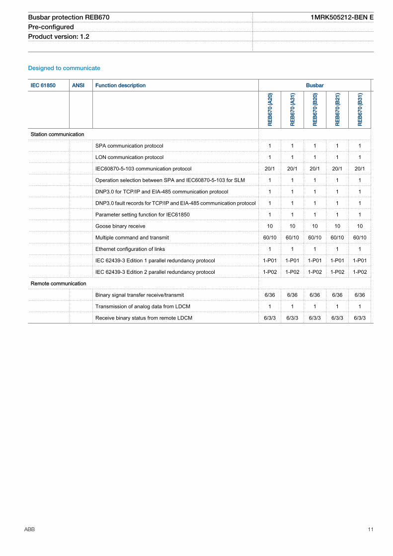
Station communication
SPA communication protocol 1 1 1 1 1
LON communication protocol 1 1 1 1 1
IEC60870-5-103 communication protocol 20/1 20/1 20/1 20/1 20/1
Operation selection between SPA and IEC60870-5-103 for SLM 1 1 1 1 1
DNP3.0 for TCP/IP and EIA-485 communication protocol 1 1 1 1 1
DNP3.0 fault records for TCP/IP and EIA-485 communication protocol 1 1 1 1 1
Parameter setting function for IEC61850 1 1 1 1 1
Goose binary receive 10 10 10 10 10
Multiple command and transmit 60/10 60/10 60/10 60/10 60/10
Ethernet configuration of links 1 1 1 1 1
IEC 62439-3 Edition 1 parallel redundancy protocol 1-P01 1-P01 1-P01 1-P01 1-P01
IEC 62439-3 Edition 2 parallel redundancy protocol 1-P02 1-P02 1-P02 1-P02 1-P02
Remote communication
Binary signal transfer receive/transmit 6/36 6/36 6/36 6/36 6/36
Transmission of analog data from LDCM 1 1 1 1 1
Receive binary status from remote LDCM 6/3/3 6/3/3 6/3/3 6/3/3 6/3/3
Busbar protection REB670 1MRK505212-BEN EPre-configured Product version: 1.2
ABB 11

Basic IED functions
IEC 61850 Function description
Basic functions included in all products
IntErrorSig Self supervision with internal event list 1
TIME Time and synchronization error 1
TimeSynch Time synchronization 1
ActiveGroup Parameter setting groups 1
Test Test mode functionality 1
ChangeLock Change lock function 1
TerminalID IED identifiers 1
Productinfo Product information 1
MiscBaseCommon Misc Base Common 1
IEDRuntimeComp IED Runtime Comp 1
RatedFreq Rated system frequency 1
SMBI Signal Matrix for binary inputs 40
SMBO Signal Matrix for binary outputs 40
SMMI Signal Matrix for mA inputs 4
SMAI Signal Matrix for analog inputs 24
Sum3Ph Summation block 3 phase 12
LocalHMI Parameter setting function for HMI in PCM600 1
LocalHMI Local HMI signals 1
AuthStatus Authority status 1
AuthorityCheck Authority check 1
AccessFTP FTP access with password 1
SPACommMap SPA communication mapping 1
DOSFRNT Denial of service, frame rate control for front port 1
DOSOEMAB Denial of service, frame rate control for OEM port AB 1
DOSOEMCD Denial of service, frame rate control for OEM port CD 1
3. Differential protectionThe function consists of differential protection algorithm,sensitive differential protection algorithm, check zonealgorithm, open CT algorithm and two supervision algorithms.
Busbar differential protectionThis protection function is intended for fast and selectivetripping of faults within protected zone. For each currentinput, the CT ratio can be set from the front HMI or via theparameter-setting tool, PCM600. In this way adaptation todifferent CT ratios is provided in the simplest way. Theminimum pick-up value for the differential current is then set
to give a suitable sensitivity for all internal faults. This settingis made directly in primary amperes. For busbar protectionapplications typical setting value for the minimum differentialoperating current is from 50% to 150% of the biggest CT.The settings can be changed from the front HMI or via theparameter-setting tool, PCM600.
All current inputs are indirectly provided with a restraintfeature. The operation is based on the well-proven RADSSpercentage restraint stabilization principle, with an extrastabilization feature to stabilize for very heavy CT saturation.Stability for external faults is guaranteed if a CT is not
Busbar protection REB670 1MRK505212-BEN EPre-configured Product version: 1.2
12 ABB

saturated for at least two milliseconds during each powersystem cycle. It is also possible to add external trippingcriteria by binary signal.
The trip command from the differential protection includingsensitive differential protection and circuit breaker failurebackup-trip commands can be set either as self-resetting orlatched. In second case the manual reset is needed in orderto reset the individual bay trip output contacts.
Sensitive differential level BZISGGIODifferential protection zones in REB670 include a sensitiveoperational level. This sensitive operational level is designedto be able to detect internal busbar earth faults in lowimpedance earthed power systems (i.e. power systems wherethe earth-fault current is limited to a certain level, typicallybetween 300A and 2000A primary by a neutral point reactoror resistor). For increased security, the sensitive differentialprotection must be externally enabled by a binary signal (e.g.from external open delta VT overvoltage relay or externalpower transformer neutral point overcurrent relay). Finally it isas well possible to set a time delay before the trip signal fromthe sensitive differential protection is given. This sensitivelevel can be alternatively used in special applications whenhigh sensitivity is required from busbar differential protection(i.e. energizing of dead bus via a long line).
Operation and operating characteristic of the sensitivedifferential protection can be set independently from theoperating characteristic of the main differential protection.However, the sensitive differential level is blocked as soon asthe total incoming current exceeds the pre-set level or whendifferential current exceed the set minimum pickup current forthe usual differential protection. Therefore, by appropriatesettings it can be ensured that this sensitive level is blockedfor all external multi-phase faults, which can cause CTsaturation. Operating characteristic of sensitive differentialcharacteristics is shown in figure 1.
Check zoneFor busbar protection in double busbar stations whendynamic zone selection is needed, it is sometimes required toinclude the overall differential zone (that is, check zone).Hence, the built-in, overall check zone is available in the IED.Because the built-in check zone current measurement is notdependent on the disconnector status, this feature ensuresstability of Busbar differential protection even for completelywrong status indication from the busbar disconnectors. It isto be noted that the overall check zone, only supervise theusual differential protection operation. The external tripcommands, breaker failure backup-trip commands andsensitive differential protection operation are not supervisedby the overall check zone.
The overall check zone has simple current operatingalgorithm, which ensures check zone operation for all internalfaults regardless the fault current distribution. To achieve this,the outgoing current from the overall check zone is used as
restraint quantity. If required, the check zone operation canbe activated externally by a binary signal.
Open CT detectionThe innovative measuring algorithm provides stability for openor short-circuited main CT secondary circuits, which meansthat no separate check zone is actually necessary. Startcurrent level for open CT detection can usually be set todetect the open circuit condition for the smallest CT. Thisbuilt-in feature allows the protection terminal to be set verysensitive, even to a lower value than the maximum CT primaryrating in the station. At detection of problems in CTsecondary circuits, the differential protection can be instantlyblocked and an alarm is given. Alternatively, the differentialprotection can be automatically desensitized in order toensure busbar differential protection stability during normalthrough-load condition. When problems in CT secondarycircuits have been found and associated error has beencorrected a manual reset must be given to the IED. This canbe done locally from the local HMI, or remotely via binaryinput or communication link.
However, it is to be noted that this feature can only be partlyutilized when the summation principle is in use.
Differential protection supervisionDual monitoring of differential protection status is available.The first monitoring feature operates after settable time delaywhen differential current is higher than the user settable level.This feature can be, for example, used to design automaticreset logic for previously described open CT detectionfeature. The second monitoring feature operates immediatelywhen the busbar through-going current is bigger than theuser settable level. Both of these monitoring features arephase segregated and they give out binary signals, which canbe either used to trigger disturbance recorder or for alarmingpurposes.
4. Zone selectionTypically CT secondary circuits from every bay in the stationare connected to the busbar protection. The built-in softwarefeature called “Zone Selection” gives a simple but efficientcontrol over the connected CTs to busbar protection IED inorder to provide fully operational differential protectionscheme for multi-zone applications on both small and largebuses.
The function consists of dedicated disconnector/circuitbreaker status monitoring algorithm, bay dedicated CT-connection control algorithm and zone interconnectionalgorithm.
Switch status monitoringFor stations with complex primary layout (that is, doublebusbar single breaker station with or without transfer bus) theinformation about busbar disconnector position in every bayis crucial information for busbar protection. The positions of
Busbar protection REB670 1MRK505212-BEN EPre-configured Product version: 1.2
ABB 13

these disconnectors then actually determine which CT input(that is, bay) is connected to which differential protectionzone. For some more advanced features like end-fault orblind-spot protection the actual status of the circuit breaker insome or even all bays can be vital information for busbarprotection as well. The switch function block is used to takethe status of two auxiliary contacts from the primary device,evaluate them and then to deliver the device primary contactposition to the rest of the zone selection logic.
For such applications typically two auxiliary contacts (that is,normally open and normally closed auxiliary contacts) fromeach relevant primary switching object shall be connected tothe IED. Then the status for every individual primary switchingobject will be determined. The dedicated function block foreach primary switching object is available in order todetermine the status of the object primary contacts. By aparameter setting one of the following two logical schemescan be selected for each primary object individually by theend user:
• If not open then closed (that is, as in RADSS schemes)
• Open or closed only when clearly indicated by auxcontact status (that is, as in INX schemes)
Table 1 gives quick overview about both schemes.
Note that the first scheme only requires fast breaking normallyclosed auxiliary contact (that is, b contact) for properoperation. The timing of normally open auxiliary contact is notcritical because it is only used for supervision of the primaryobject status. The second scheme in addition requiresproperly timed-adjusted, early-making normally open auxiliarycontact (that is, early making a contact) for proper operation.
Regardless which scheme is used the time-delayeddisconnector/circuit breaker status supervision alarm isavailable (that is, 00 or 11 auxiliary contact status). How twointegrated differential protection zones behave whendisconnector alarm appears is freely configurable by the enduser.
It is possible by a parameter setting to override the primaryobject status as either permanently open or permanentlyclosed. This feature can be useful during testing, installationand commissioning of the busbar protection scheme. At thesame time, separate alarm is given to indicate that the actualobject status is overwritten by a setting parameter.
It is to be noted that it is as well possible to use only normallyclosed auxiliary contacts for Zone Selection logic. In that casethe Switch function blocks are not used.
Table 1. Treatment of primary object auxiliary contact status
Primary equipment Status in busbar protection Alarm facility
Normally Openauxiliarycontact status(that is,“closed” or“a” contact)
NormallyClosedauxiliarycontact status(that is,“open” or “b”contact)
when“Scheme 1RADSS”is selected
when“Scheme 2INX”is selected
Alarm aftersettable timedelay
Information visible on local HMI
open open closed Last positionsaved
yes intermediate_00
open
closed open open no open
closed
open closed closed no closed
closed closed closed closed yes badState_11
BayEach CT input is allocated to one dedicated bay functionblock. This function block is used to provide complete userinterface for all signals from and towards this bay. It is alsoused to influence bay measured current.
It is possible by a parameter setting CTConnection to connector disconnect the CT input to the bay function block. Oncethe CT input is connected to the bay function block thisassociated current input can be included to or excluded from
the two internally available differential functions in software.This can be done by a parameter setting for simple stationlayouts (that is, one-and-a-half breaker stations) oralternatively via dedicated logical scheme (that is, doublebusbar stations). For each bay the end user have to selectone of the following five alternatives:
Busbar protection REB670 1MRK505212-BEN EPre-configured Product version: 1.2
14 ABB

• Permanently connect this bay current to zone A (that is,ZA)
• Permanently connect this bay current to zone B (that is,ZB)
• Permanently connect this bay current to zone A andinverted bay current to ZB (that is, ZA and ZB)
• Connect this bay current to ZA or ZB depending on thelogical status of the two input binary signals available onthis bay function block. These two input signals willinclude measured current to the respective zone whentheir logical value is one (that is, CntrlIncludes). Thisoption is used together with above described Switchfunction blocks in order to provide complete ZoneSelection logic
• Connect the bay current to ZA or ZB depending on thelogical status of the two input binary signals available onthis bay function block. These two signals will includemeasured current to the respective zone when theirlogical value is zero (that is, CntrlExcludes). This optionis typically used when only normally closed auxiliarycontacts from the busbar disconnector are available tothe Zone Selection logic
At the same time, an additional feature for instantaneous ortime delayed disconnection or even inversion of theconnected bay current via separate logical signals is alsoavailable. This feature is provided in order to facilitate for bus-section or bus-coupler CT disconnection for tie-breakers witha CT only on one side of the circuit breaker. This ensurescorrect and fast fault clearance of faults between the CT andthe circuit breaker within these bays. The same feature canbe individually used in any feeder bay to optimize Busbardifferential protection performance, when feeder circuitbreaker is open. Thus, the end-fault protection for faultsbetween circuit breaker and the CT is available. However, touse this feature circuit breaker auxiliary contacts and closingcommand to the circuit breaker shall be wired to the binaryinputs of the IED. Therefore, he IED offers best possiblecoverage for these special faults between CT and circuitbreaker in feeder and bus-section/bus-coupler bays.
Within the Bay function block it is decided by a parametersetting how this bay should behave during zoneinterconnection (that is, load transfer). For each bayindividually one of the following three options can be selected:
• Bay current is forced out from both zones during zoneinterconnection (used for bus-coupler bays)
• Bay current is unconditionally forced into both zonesduring zone interconnection (used in special applications)
• Bay current is connected to both zones during zoneinterconnection if the bay was previously connected toone of the two zones (typically used for feeder bays)
The third option ensures that the feeder, which is out ofservice, is not connected to any of the two zones during zoneinterconnection.
Within the Bay function block it is decided by a parametersetting whether this bay should be connected to the checkzone or not. In this way the end user has simple control overthe bays, which shall be connected to the overall check zone.
By appropriate configuration logic it is possible to take anybay (that is, CT input) out of service. This can be done fromthe local HMI or externally via binary signal. In that case allinternal current measuring functions (that is, differentialprotection, sensitive differential protection, check zone,breaker failure protection and overcurrent protection) aredisabled. At the same time, any trip command to this baycircuit breaker can be inhibited.
Via two dedicated binary input signals it is possible to:
• Trip only the bay circuit breaker (used for integrated OCprotection tripping)
• Trip the whole differential zone to which this bay ispresently connected (used for backup-trip commandfrom either integrated or external bay circuit breakerfailure protection)
Finally dedicated trip binary output from the Bay functionblock is available in order to provide common trip signal tothe bay circuit breaker from busbar differential protection,breaker failure protection, backup overcurrent protection andso on.
In this way the interface to the user is kept as simple aspossible and IED engineering work is quite straight forward.
Zone interconnection (Load transfer)When this feature is activated the two integrated differentialprotection zones are merged into one common, overalldifferential zone. This feature is required in double busbarstations when in any of the feeder bays both busbardisconnectors are closed at the same time (that is, loadtransfer). As explained in above section Bay each CT inputwill then behave in the pre-set way in order to ensure propercurrent balancing during this special condition. This featurecan be started automatically (when Zone Selection logicdetermines that both busbar disconnectors in one feeder bayare closed at the same time) or externally via dedicated binarysignal. If this feature is active for longer time than the pre-setvale the alarm signal is given.
Busbar protection REB670 1MRK505212-BEN EPre-configured Product version: 1.2
ABB 15

5. Current protection
Four step phase overcurrent protection OC4PTOCThe four step phase overcurrent protection functionOC4PTOC has an inverse or definite time delay independentfor step 1 and 4 separately. Step 2 and 3 are always definitetime delayed.
All IEC and ANSI inverse time characteristics are availabletogether with an optional user defined time characteristic.
The directional function is voltage polarized with memory. Thefunction can be set to be directional or non-directionalindependently for each of the steps.
Second harmonic blocking level can be set for the functionand can be used to block each step individually
This function can be used as a backup bay protection (e.g.for transformers, reactors, shunt capacitors and tie-breakers).A special application is to use this phase overcurrentprotection to detect short-circuits between the feeder circuitbreaker and feeder CT in a feeder bay when the circuitbreaker is open. This functionality is called end-faultprotection. In such case unnecessarily operation of thebusbar differential protection can be prevented and only fastovercurrent trip signal can be sent to the remote line end. Inorder to utilize this functionality the circuit breaker status andCB closing command must be connected to the REB670.One of the overcurrent steps can be set and configured to actas end-fault protection in REB670.
The function is normally used as end fault protection to clearfaults between current transformer and circuit breaker.
Four step single phase overcurrent protection PH4SPTOCFour step single phase overcurrent protection(PH4SPTOC)has an inverse or definite time delay independentfor each step separately.
All IEC and ANSI time delayed characteristics are availabletogether with an optional user defined time characteristic.
The function is normally used as end fault protection to clearfaults between current transformer and circuit breaker.
Breaker failure protection CCRBRFBreaker failure protection (CCRBRF) ensures fast back-uptripping of surrounding breakers in case the own breaker failsto open. CCRBRF can be current based, contact based, oran adaptive combination of these two conditions.
Current check with extremely short reset time is used ascheck criterion to achieve high security against inadvertentoperation.
Contact check criteria can be used where the fault currentthrough the breaker is small.
CCRBRF can be single- or three-phase initiated to allow usewith single phase tripping applications. For the three-phaseversion of CCRBRF the current criteria can be set to operateonly if two out of four for example, two phases or one phaseplus the residual current start. This gives a higher security tothe back-up trip command.
CCRBRF function can be programmed to give a single- orthree-phase re-trip of the own breaker to avoid unnecessarytripping of surrounding breakers at an incorrect initiation dueto mistakes during testing.
Breaker failure protection, single phase version CCSRBRFBreaker failure protection, single phase version (CCSRBRF)function ensures fast back-up tripping of surroundingbreakers.
A current check with extremely short reset time is used ascheck criteria to achieve a high security against unnecessaryoperation.
CCSRBRF can be programmed to give a re-trip of the ownbreaker to avoid unnecessary tripping of surroundingbreakers at an incorrect starting due to mistakes duringtesting.
6. Control
Autorecloser SMBRRECThe autoreclosing function provides high-speed and/ordelayed three pole autoreclosing. The autoreclosing can beused for delayed busbar restoration. One Autorecloser(SMBRREC) per zone can be made available.
Logic rotating switch for function selection and LHMIpresentation SLGGIOThe logic rotating switch for function selection and LHMIpresentation (SLGGIO) (or the selector switch function block)is used to get a selector switch functionality similar to the oneprovided by a hardware selector switch. Hardware selectorswitches are used extensively by utilities, in order to havedifferent functions operating on pre-set values. Hardwareswitches are however sources for maintenance issues, lowersystem reliability and an extended purchase portfolio. Thelogic selector switches eliminate all these problems.
Selector mini switch VSGGIOThe Selector mini switch VSGGIO function block is amultipurpose function used for a variety of applications, as ageneral purpose switch.
VSGGIO can be controlled from the menu or from a symbolon the single line diagram (SLD) on the local HMI.
Single point generic control 8 signals SPC8GGIOThe Single point generic control 8 signals (SPC8GGIO)function block is a collection of 8 single point commands,designed to bring in commands from REMOTE (SCADA) to
Busbar protection REB670 1MRK505212-BEN EPre-configured Product version: 1.2
16 ABB

those parts of the logic configuration that do not needextensive command receiving functionality (for example,SCSWI). In this way, simple commands can be sent directlyto the IED outputs, without confirmation. Confirmation (status)of the result of the commands is supposed to be achieved byother means, such as binary inputs and SPGGIO functionblocks. The commands can be pulsed or steady.
AutomationBits, command function for DNP3.0 AUTOBITSAutomationBits function for DNP3 (AUTOBITS) is used withinPCM600 to get into the configuration of the commandscoming through the DNP3 protocol. The AUTOBITS functionplays the same role as functions GOOSEBINRCV (for IEC61850) and MULTICMDRCV (for LON).
Single command, 16 signalsThe IEDs can receive commands either from a substationautomation system or from the local HMI. The commandfunction block has outputs that can be used, for example, tocontrol high voltage apparatuses or for other user definedfunctionality.
7. Logic
Configurable logic blocksA number of logic blocks and timers are available for the userto adapt the configuration to the specific application needs.
• OR function block.
• INVERTER function blocks that inverts the input signal.
• PULSETIMER function block can be used, for example, forpulse extensions or limiting of operation of outputs, settablepulse time.
• GATE function block is used for whether or not a signalshould be able to pass from the input to the output.
• XOR function block.
• LOOPDELAY function block used to delay the output signalone execution cycle.
• TIMERSET function has pick-up and drop-out delayedoutputs related to the input signal. The timer has a settabletime delay.
• AND function block.
• SRMEMORY function block is a flip-flop that can set orreset an output from two inputs respectively. Each blockhas two outputs where one is inverted. The memory settingcontrols if the block's output should reset or return to thestate it was, after a power interruption. Set input haspriority.
• RSMEMORY function block is a flip-flop that can reset orset an output from two inputs respectively. Each block hastwo outputs where one is inverted. The memory setting
controls if the block's output should reset or return to thestate it was, after a power interruption. RESET input haspriority.
Fixed signal function blockThe Fixed signals function (FXDSIGN) generates a number ofpre-set (fixed) signals that can be used in the configuration ofan IED, either for forcing the unused inputs in other functionblocks to a certain level/value, or for creating certain logic.
8. Monitoring
Measurements CVMMXN, CMMXU, VNMMXU, VMMXU,CMSQI, VMSQIThe measurement functions are used to get on-lineinformation from the IED. These service values make itpossible to display on-line information on the local HMI andon the Substation automation system about:
• measured voltages, currents, frequency, active, reactiveand apparent power and power factor
• primary and secondary phasors• positive, negative and zero sequence currents and
voltages• mA, input currents• pulse counters
Event counter CNTGGIOEvent counter (CNTGGIO) has six counters which are used forstoring the number of times each counter input has beenactivated.
Disturbance report DRPRDREComplete and reliable information about disturbances in theprimary and/or in the secondary system together withcontinuous event-logging is accomplished by the disturbancereport functionality.
Disturbance report DRPRDRE, always included in the IED,acquires sampled data of all selected analog input and binarysignals connected to the function block with a, maximum of40 analog and 96 binary signals.
The Disturbance report functionality is a common name forseveral functions:
• Event list• Indications• Event recorder• Trip value recorder• Disturbance recorder
The Disturbance report function is characterized by greatflexibility regarding configuration, starting conditions,recording times, and large storage capacity.
Busbar protection REB670 1MRK505212-BEN EPre-configured Product version: 1.2
ABB 17

A disturbance is defined as an activation of an input to theAxRADR or BxRBDR function blocks, which are set to triggerthe disturbance recorder. All signals from start of pre-faulttime to the end of post-fault time will be included in therecording.
Every disturbance report recording is saved in the IED in thestandard Comtrade format. The same applies to all events,which are continuously saved in a ring-buffer. The local HMI isused to get information about the recordings. Thedisturbance report files may be uploaded to PCM600 forfurther analysis using the disturbance handling tool.
Event list DRPRDREContinuous event-logging is useful for monitoring the systemfrom an overview perspective and is a complement to specificdisturbance recorder functions.
The event list logs all binary input signals connected to theDisturbance report function. The list may contain up to 1000time-tagged events stored in a ring-buffer.
Indications DRPRDRETo get fast, condensed and reliable information aboutdisturbances in the primary and/or in the secondary system itis important to know, for example binary signals that havechanged status during a disturbance. This information is usedin the short perspective to get information via the local HMI ina straightforward way.
There are three LEDs on the local HMI (green, yellow andred), which will display status information about the IED andthe Disturbance report function (triggered).
The Indication list function shows all selected binary inputsignals connected to the Disturbance report function thathave changed status during a disturbance.
Event recorder DRPRDREQuick, complete and reliable information about disturbancesin the primary and/or in the secondary system is vital, forexample, time-tagged events logged during disturbances.This information is used for different purposes in the shortterm (for example corrective actions) and in the long term (forexample functional analysis).
The event recorder logs all selected binary input signalsconnected to the Disturbance report function. Each recordingcan contain up to 150 time-tagged events.
The event recorder information is available for thedisturbances locally in the IED.
The event recording information is an integrated part of thedisturbance record (Comtrade file).
Trip value recorder DRPRDREInformation about the pre-fault and fault values for currentsand voltages are vital for the disturbance evaluation.
The Trip value recorder calculates the values of all selectedanalog input signals connected to the Disturbance reportfunction. The result is magnitude and phase angle before andduring the fault for each analog input signal.
The trip value recorder information is available for thedisturbances locally in the IED.
The trip value recorder information is an integrated part of thedisturbance record (Comtrade file).
Disturbance recorder DRPRDREThe Disturbance recorder function supplies fast, completeand reliable information about disturbances in the powersystem. It facilitates understanding system behavior andrelated primary and secondary equipment during and after adisturbance. Recorded information is used for differentpurposes in the short perspective (for example correctiveactions) and long perspective (for example functional analysis).
The Disturbance recorder acquires sampled data fromselected analog- and binary signals connected to theDisturbance report function (maximum 40 analog and 96binary signals). The binary signals available are the same asfor the event recorder function.
The function is characterized by great flexibility and is notdependent on the operation of protection functions. It canrecord disturbances not detected by protection functions. Upto ten seconds of data before the trigger instant can be savedin the disturbance file.
The disturbance recorder information for up to 100disturbances are saved in the IED and the local HMI is usedto view the list of recordings.
Event functionWhen using a Substation Automation system with LON orSPA communication, time-tagged events can be sent atchange or cyclically from the IED to the station level. Theseevents are created from any available signal in the IED that isconnected to the Event function (EVENT). The event functionblock is used for LON and SPA communication.
Analog and double indication values are also transferredthrough EVENT function.
IEC61850 generic communication I/O functions MVGGIOIEC61850 generic communication I/O functions (MVGGIO)function is used to send the instantaneous value of an analogsignal to other systems or equipment in the substation. It canalso be used inside the same IED, to attach a RANGE aspectto an analog value and to permit measurement supervision onthat value.
Busbar protection REB670 1MRK505212-BEN EPre-configured Product version: 1.2
18 ABB

Measured value expander block RANGE_XPThe current and voltage measurements functions (CVMMXN,CMMXU, VMMXU and VNMMXU), current and voltagesequence measurement functions (CMSQI and VMSQI) andIEC 61850 generic communication I/O functions (MVGGIO)are provided with measurement supervision functionality. Allmeasured values can be supervised with four settable limits:low-low limit, low limit, high limit and high-high limit. Themeasure value expander block (RANGE_XP) has beenintroduced to enable translating the integer output signal fromthe measuring functions to 5 binary signals: below low-lowlimit, below low limit, normal, above high-high limit or abovehigh limit. The output signals can be used as conditions in theconfigurable logic or for alarming purpose.
9. Basic IED functions
Time synchronizationThe time synchronization source selector is used to select acommon source of absolute time for the IED when it is a partof a protection system. This makes it possible to compareevent and disturbance data between all IEDs in a stationautomation system.
10. Human machine interface
Human machine interfaceThe local HMI is equipped with a LCD that is used amongother things to locally display the following crucial information:
• Connection of each bay, respecting the two differentialprotection zones and the check zone. In the ParameterSetting Tool the user sets individual bay names tofacilitate the identification of each primary bay for stationpersonnel.
• Status of each individual primary switchgear device, forexample, open, closed, 00 as intermediate state and 11as bad state. In PCM600 the user sets the individualprimary switchgear object names to facilitate theidentification of each switchgear device for the stationpersonnel.
The local HMI is divided into zones with different functionality.
• Status indication LEDs.• Alarm indication LEDs, which consist of 15 LEDs (6 red
and 9 yellow) with user printable label. All LEDs areconfigurable from PCM600.
• Liquid crystal display (LCD).• Keypad with push buttons for control and navigation
purposes, switch for selection between local and remotecontrol and reset.
• Isolated RJ45 communication port.
IEC06000143 V1 EN
Figure 11. Example of medium graphic HMI
Busbar protection REB670 1MRK505212-BEN EPre-configured Product version: 1.2
ABB 19

IEC06000191 V1 EN
Figure 12. Bay to zone connection example
1 User settable bay name
2 Internally used bay FB
3 Connections to internal zones
IEC06000192 V1 EN
Figure 13. Example of status of primary switchgear objects
1 User settable switchgear names
2 Switchgear object status
11. Station communication
OverviewEach IED is provided with a communication interface,enabling it to connect to one or many substation levelsystems or equipment, either on the Substation Automation(SA) bus or Substation Monitoring (SM) bus.
Following communication protocols are available:
• IEC 61850-8-1 communication protocol• LON communication protocol• SPA or IEC 60870-5-103 communication protocol• DNP3.0 communication protocol
Theoretically, several protocols can be combined in the sameIED.
IEC 61850-8-1 communication protocolThe IED is equipped with single or double optical Ethernetrear ports (order dependent) for IEC 61850-8-1 station buscommunication. The IEC 61850-8-1 communication is alsopossible from the optical Ethernet front port. IEC 61850-8-1protocol allows intelligent electrical devices (IEDs) fromdifferent vendors to exchange information and simplifiessystem engineering. Peer-to-peer communication according
Busbar protection REB670 1MRK505212-BEN EPre-configured Product version: 1.2
20 ABB
to GOOSE is part of the standard. Disturbance files uploadingis provided.
Serial communication, LONExisting stations with ABB station bus LON can be extendedwith use of the optical LON interface. This allows full SAfunctionality including peer-to-peer messaging andcooperation between existing ABB IED's and the new IED670.
SPA communication protocolA single glass or plastic port is provided for the ABB SPAprotocol. This allows extensions of simple substationautomation systems but the main use is for SubstationMonitoring Systems SMS.
IEC 60870-5-103 communication protocolA single glass or plastic port is provided for theIEC60870-5-103 standard. This allows design of simplesubstation automation systems including equipment fromdifferent vendors. Disturbance files uploading is provided.
DNP3.0 communication protocolAn electrical RS485 and an optical Ethernet port is availablefor the DNP3.0 communication. DNP3.0 Level 2communication with unsolicited events, time synchronizingand disturbance reporting is provided for communication toRTUs, Gateways or HMI systems.
Multiple command and transmitWhen 670 IED's are used in Substation Automation systemswith LON, SPA or IEC60870-5-103 communication protocolsthe Event and Multiple Command function blocks are used asthe communication interface for vertical communication tostation HMI and gateway and as interface for horizontal peer-to-peer communication (over LON only).
IEC 62439-3 Parallel Redundant ProtocolRedundant station bus communication according to IEC62439-3 Edition 1 and IEC 62439-3 Edition 2 are available asoptions in 670 series IEDs. IEC 62439-3 parallel redundantprotocol is an optional quantity and the selection is made atordering. Redundant station bus communication according toIEC 62439-3 uses both port AB and port CD on the OEMmodule.
Select IEC 62439-3 Edition 1 protocol atthe time of ordering when an existingredundant station bus DuoDriver installationis extended.Select IEC 62439-3 Edition 2 protocol atthe time of ordering for new installationswith redundant station bus.IEC 62439-3 Edition 1 is NOT compatiblewith IEC 62439-3 Edition 2.
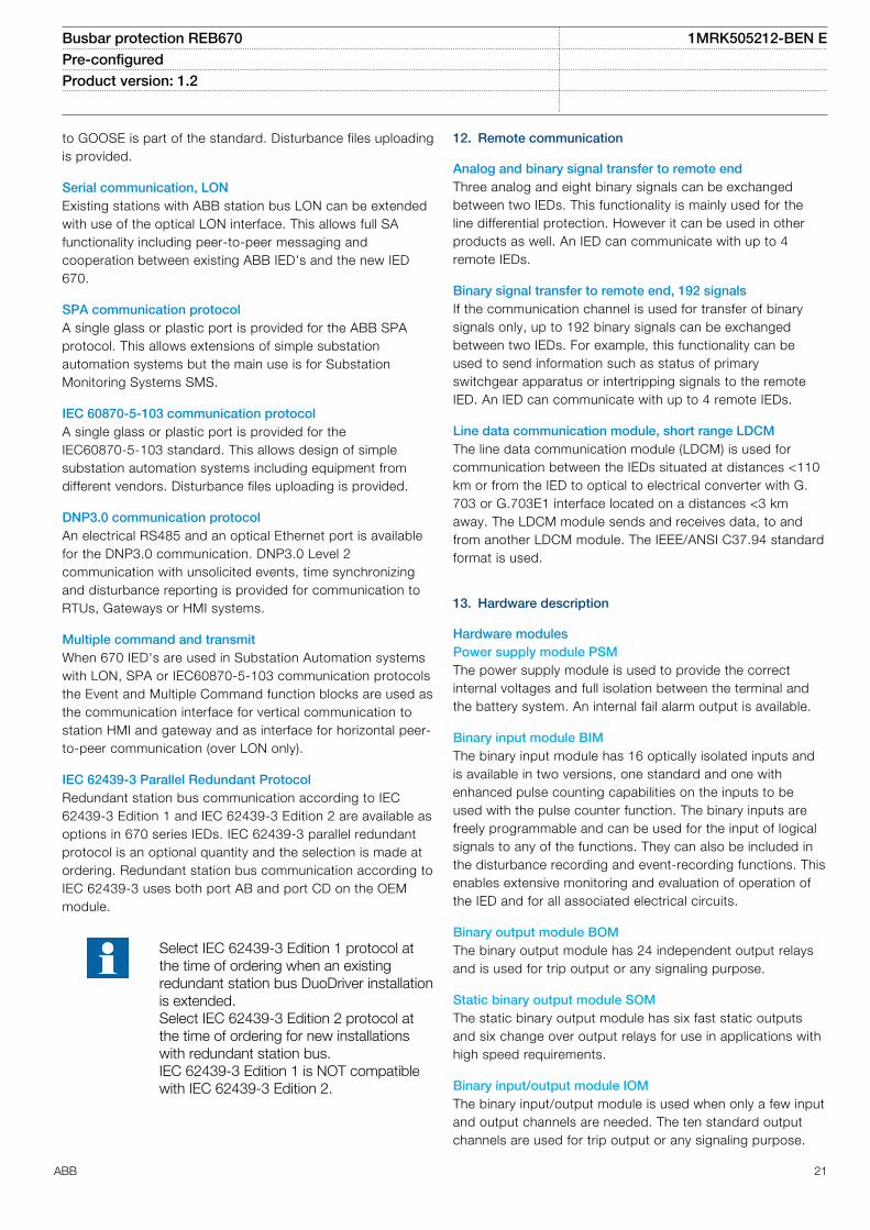
12. Remote communication
Analog and binary signal transfer to remote endThree analog and eight binary signals can be exchangedbetween two IEDs. This functionality is mainly used for theline differential protection. However it can be used in otherproducts as well. An IED can communicate with up to 4remote IEDs.
Binary signal transfer to remote end, 192 signalsIf the communication channel is used for transfer of binarysignals only, up to 192 binary signals can be exchangedbetween two IEDs. For example, this functionality can beused to send information such as status of primaryswitchgear apparatus or intertripping signals to the remoteIED. An IED can communicate with up to 4 remote IEDs.
Line data communication module, short range LDCMThe line data communication module (LDCM) is used forcommunication between the IEDs situated at distances <110km or from the IED to optical to electrical converter with G.703 or G.703E1 interface located on a distances <3 kmaway. The LDCM module sends and receives data, to andfrom another LDCM module. The IEEE/ANSI C37.94 standardformat is used.
13. Hardware description
Hardware modulesPower supply module PSMThe power supply module is used to provide the correctinternal voltages and full isolation between the terminal andthe battery system. An internal fail alarm output is available.
Binary input module BIMThe binary input module has 16 optically isolated inputs andis available in two versions, one standard and one withenhanced pulse counting capabilities on the inputs to beused with the pulse counter function. The binary inputs arefreely programmable and can be used for the input of logicalsignals to any of the functions. They can also be included inthe disturbance recording and event-recording functions. Thisenables extensive monitoring and evaluation of operation ofthe IED and for all associated electrical circuits.
Binary output module BOMThe binary output module has 24 independent output relaysand is used for trip output or any signaling purpose.
Static binary output module SOMThe static binary output module has six fast static outputsand six change over output relays for use in applications withhigh speed requirements.
Binary input/output module IOMThe binary input/output module is used when only a few inputand output channels are needed. The ten standard outputchannels are used for trip output or any signaling purpose.
Busbar protection REB670 1MRK505212-BEN EPre-configured Product version: 1.2
ABB 21
The two high speed signal output channels are used forapplications where short operating time is essential. Eightoptically isolated binary inputs cater for required binary inputinformation.
Optical ethernet module OEMThe optical fast-ethernet module is used to connect an IED tothe communication buses (like the station bus) that use theIEC 61850-8-1 protocol (port A, B). The module has one ortwo optical ports with ST connectors.
Serial and LON communication module SLM, supports SPA/IEC 60870-5-103, LON and DNP 3.0The serial and LON communication module (SLM) is used forSPA, IEC 60870-5-103, DNP3 and LON communication. Themodule has two optical communication ports for plastic/plastic, plastic/glass or glass/glass. One port is used for serialcommunication (SPA, IEC 60870-5-103 and DNP3 port ordedicated IEC 60870-5-103 port depending on ordered SLMmodule) and one port is dedicated for LON communication.
Line data communication module LDCMEach module has one optical port, one for each remote endto which the IED communicates.
Alternative cards for Short range (850 nm multi mode) areavailable.
Galvanic RS485 serial communication moduleThe Galvanic RS485 communication module (RS485) is usedfor DNP3.0 communication. The module has one RS485
communication port. The RS485 is a balanced serialcommunication that can be used either in 2-wire or 4-wireconnections. A 2-wire connection uses the same signal for RXand TX and is a multidrop communication with no dedicatedMaster or slave. This variant requires however a control of theoutput. The 4-wire connection has separated signals for RXand TX multidrop communication with a dedicated Masterand the rest are slaves. No special control signal is needed inthis case.
GPS time synchronization module GTMThis module includes a GPS receiver used for timesynchronization. The GPS has one SMA contact forconnection to an antenna. It also includes an optical PPS ST-connector output.
IRIG-B Time synchronizing moduleThe IRIG-B time synchronizing module is used for accuratetime synchronizing of the IED from a station clock.
Transformer input module TRMThe transformer input module is used to galvanically separateand transform the secondary currents and voltages generatedby the measuring transformers. The module has twelve inputsin different combinations of currents and voltage inputs.
Alternative connectors of Ring lug or Compression type canbe ordered.
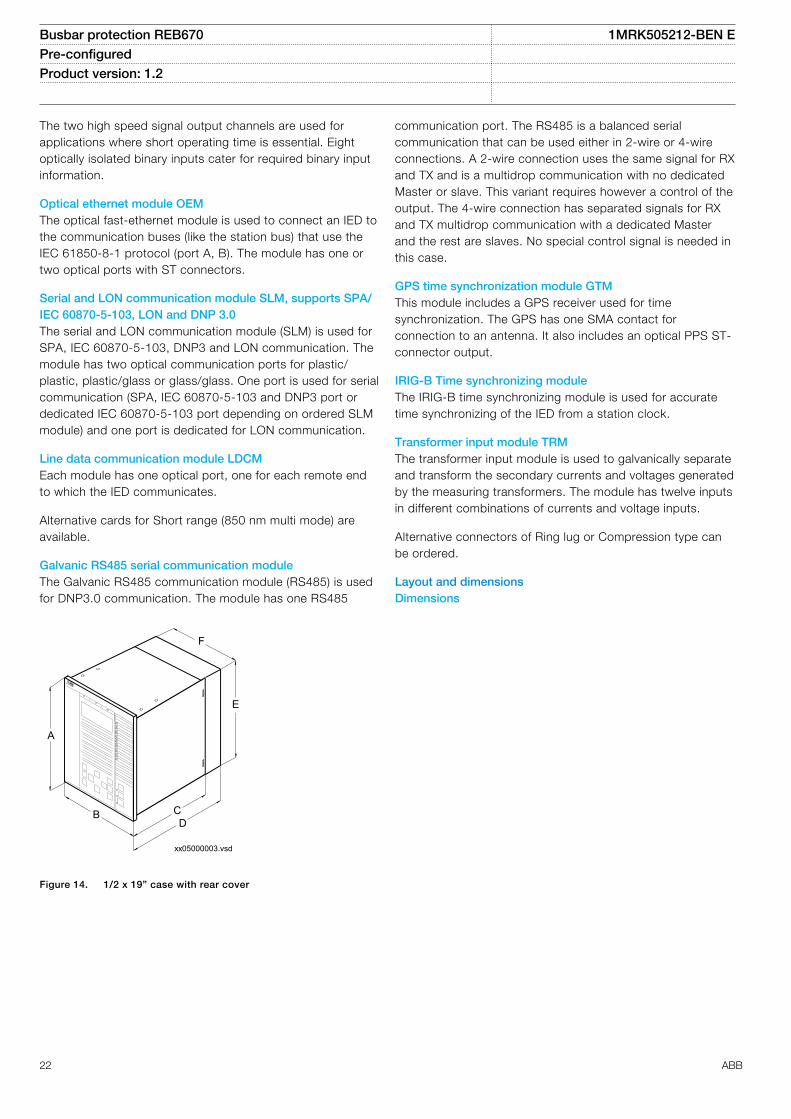
Layout and dimensionsDimensions
xx05000003.vsd
CB
E
F
A
D
IEC05000003 V1 EN
Figure 14. 1/2 x 19” case with rear cover
Busbar protection REB670 1MRK505212-BEN EPre-configured Product version: 1.2
22 ABB

xx05000004.vsdIEC05000004 V1 EN
Figure 15. Side-by-side mounting
Case size A B C D E F
6U, 1/2 x 19” 265.9 223.7 201.1 242.1 252.9 205.7
6U, 3/4 x 19” 265.9 336.0 201.1 242.1 252.9 318.0
6U, 1/1 x 19” 265.9 448.1 201.1 242.1 252.9 430.3
(mm)
Mounting alternatives• 19” rack mounting kit• Flush mounting kit with cut-out dimensions:
– 1/2 case size (h) 254.3 mm (w) 210.1 mm– 1/1 case size (h) 254.3 mm (w) 434.7 mm
• Wall mounting kit
See ordering for details about available mounting alternatives.
Busbar protection REB670 1MRK505212-BEN EPre-configured Product version: 1.2
ABB 23

14. Connection diagrams
Table 2. Designations for 1/2 x 19” casing with 1 TRM slot
1MRK002801-AC-2-670-1.2-PG V1 EN
Module Rear Positions
PSM X11
BIM, BOM, SOM, IOM orMIM
X31 and X32 etc. to X51and X52
SLM X301:A, B, C, D
LDCM, IRIG-B or RS485 X302
LDCM or RS485 X303
OEM X311:A, B, C, D
LDCM, RS485 or GTM X312, 313
TRM X401
Table 3. Designations for 3/4 x 19” casing with 1 TRM slot
1MRK002801-AC-3-670-1.2-PG V1 EN
Module Rear Positions
PSM X11
BIM, BOM, SOM, IOM orMIM
X31 and X32 etc. toX101 and X102
SLM X301:A, B, C, D
LDCM, IRIG-B or RS485 X302
LDCM or RS485 X303
OEM X311:A, B, C, D
LDCM, RS485 or GTM X312, X313
TRM X401
Busbar protection REB670 1MRK505212-BEN EPre-configured Product version: 1.2
24 ABB

Table 4. Designations for 1/1 x 19” casing with 2 TRM slots
1MRK002801-AC-6-670-1.2-PG V1 EN
Module Rear Positions
PSM X11
BIM, BOM, SOM,IOM or MIM
X31 and X32 etc. to X131and X132
SLM X301:A, B, C, D
LDCM, IRIG-B orRS485
X302
LDCM or RS485 X303
OEM X311:A, B, C, D
LDCM, RS485 orGTM
X312, X313, X322, X323
TRM 1 X401
TRM 2 X411
Busbar protection REB670 1MRK505212-BEN EPre-configured Product version: 1.2
ABB 25

1MRK002801-AC-10-670-1.2-PG V1 EN
Figure 16. Transformer input module (TRM)
■ Indicates high polarity
CT/VT-input designation according to figure 16
Cur
rent
/vol
tage
conf
igur
atio
n(5
0/60
Hz)
AI01 AI02 AI03 AI04 AI05 AI06 AI07 AI08 AI09 AI10 AI11 AI12
12I, 1A 1A 1A 1A 1A 1A 1A 1A 1A 1A 1A 1A 1A12I, 5A 5A 5A 5A 5A 5A 5A 5A 5A 5A 5A 5A 5A
Note that internal polarity can be adjusted by setting of analog input CT neutral direction and/or on SMAI pre-processing function blocks.
Busbar protection REB670 1MRK505212-BEN EPre-configured Product version: 1.2
26 ABB
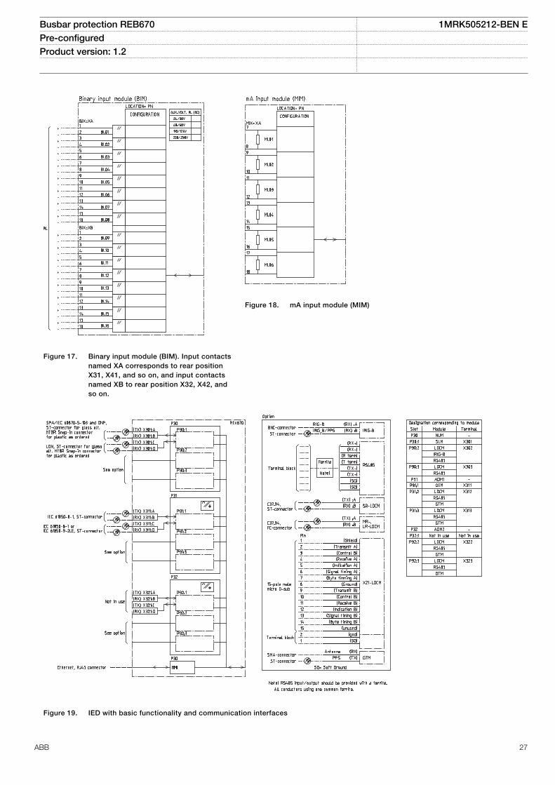
1MRK002801-AC-11-670-1.2-PG V1 EN
Figure 17. Binary input module (BIM). Input contactsnamed XA corresponds to rear positionX31, X41, and so on, and input contactsnamed XB to rear position X32, X42, andso on.
1MRK002801-AC-15-670-1.2-PG V1 EN
Figure 18. mA input module (MIM)
1MRK002801-AC-8-670-1.2-PG V1 EN
Figure 19. IED with basic functionality and communication interfaces
Busbar protection REB670 1MRK505212-BEN EPre-configured Product version: 1.2
ABB 27

1MRK002801-AC-7-670-1.2-PG V1 EN
Figure 20. Power supply module (PSM)
1MRK002801-AC-12-670-1.2-PG V1 EN
Figure 21. Binary output module (BOM). Output contacts named XA corresponds to rear position X31, X41, and so on, and outputcontacts named XB to rear position X32, X42, and so on.
Busbar protection REB670 1MRK505212-BEN EPre-configured Product version: 1.2
28 ABB

1MRK002801-AC-13-670-1.2-PG V1 EN
Figure 22. Static output module (SOM)
1MRK002801-AC-14-670-1.2-PG V1 EN
Figure 23. Binary in/out module (IOM). Input contacts named XA corresponds to rear position X31, X41, and so on, and output contactsnamed XB to rear position X32, X42, and so on.
Busbar protection REB670 1MRK505212-BEN EPre-configured Product version: 1.2
ABB 29

15. Technical data
General
Definitions
Reference value The specified value of an influencing factor to which are referred the characteristics of the equipment
Nominal range The range of values of an influencing quantity (factor) within which, under specified conditions, the equipment meets thespecified requirements
Operative range The range of values of a given energizing quantity for which the equipment, under specified conditions, is able to perform itsintended functions according to the specified requirements
Energizing quantities, rated values and limitsAnalog inputs
Table 5. TRM - Energizing quantities, rated values and limits for protection transformer modules
Quantity Rated value Nominal range
Current Ir = 1 or 5 A (0.2-40) × Ir
Operative range (0-100) x Ir
Permissive overload 4 × Ir cont.100 × Ir for 1 s *)
Burden < 150 mVA at Ir = 5 A< 20 mVA at Ir = 1 A
Frequency fr = 50/60 Hz ± 5%
*) max. 350 A for 1 s when COMBITEST test switch is included.
Table 6. OEM - Optical ethernet module
Quantity Rated value
Number of channels 1 or 2
Standard IEEE 802.3u 100BASE-FX
Type of fiber 62.5/125 mm multimode fibre
Wave length 1300 nm
Optical connector Type ST
Communication speed Fast Ethernet 100 MB
Auxiliary DC voltage
Table 7. PSM - Power supply module
Quantity Rated value Nominal range
Auxiliary dc voltage, EL (input) EL = (24 - 60) VEL = (90 - 250) V
EL ± 20%EL ± 20%
Power consumption 50 W typically -
Auxiliary DC power in-rush < 5 A during 0.1 s -
Busbar protection REB670 1MRK505212-BEN EPre-configured Product version: 1.2
30 ABB

Binary inputs and outputs
Table 8. BIM - Binary input module
Quantity Rated value Nominal range
Binary inputs 16 -
DC voltage, RL 24/30 V48/60 V110/125 V220/250 V
RL ± 20%RL ± 20%RL ± 20%RL ± 20%
Power consumption24/30 V, 50mA48/60 V, 50mA110/125 V, 50mA220/250 V, 50mA220/250 V, 110mA
max. 0.05 W/inputmax. 0.1 W/inputmax. 0.2 W/inputmax. 0.4 W/inputmax. 0.5 W/input
-
Counter input frequency 10 pulses/s max -
Oscillating signal discriminator Blocking settable 1–40 HzRelease settable 1–30 Hz
Debounce filter Settable 1–20ms
Maximum 176 binary input channels maybe activated simultaneously with influencingfactors within nominal range.
Table 9. BIM - Binary input module with enhanced pulse counting capabilities
Quantity Rated value Nominal range
Binary inputs 16 -
DC voltage, RL 24/30 V48/60 V110/125 V220/250 V
RL ± 20%RL ± 20%RL ± 20%RL ± 20%
Power consumption24/30 V48/60 V110/125 V220/250 V
max. 0.05 W/inputmax. 0.1 W/inputmax. 0.2 W/inputmax. 0.4 W/input
-
Counter input frequency 10 pulses/s max -
Balanced counter input frequency 40 pulses/s max -
Oscillating signal discriminator Blocking settable 1–40 HzRelease settable 1–30 Hz
Maximum 176 binary input channels maybe activated simultaneously with influencingfactors within nominal range.
Busbar protection REB670 1MRK505212-BEN EPre-configured Product version: 1.2
ABB 31

Table 10. IOM - Binary input/output module
Quantity Rated value Nominal range
Binary inputs 8 -
DC voltage, RL 24/30 V48/60 V110/125 V220/250 V
RL ± 20%RL ± 20%RL ± 20%RL ± 20%
Power consumption24/30 V, 50 mA48/60 V, 50 mA110/125 V, 50 mA220/250 V, 50 mA220/250 V, 110 mA
max. 0.05 W/inputmax. 0.1 W/inputmax. 0.2 W/inputmax. 0.4 W/inputmax. 0.5 W/input
-
Counter input frequency 10 pulses/s max
Oscillating signal discriminator Blocking settable 1-40 HzRelease settable 1-30 Hz
Debounce filter Settable 1-20 ms
Maximum 176 binary input channels maybe activated simultaneously with influencingfactors within nominal range.
Table 11. IOM - Binary input/output module contact data (reference standard: IEC 61810-2)
Function or quantity Trip and signal relays Fast signal relays (parallelreed relay)
Binary outputs 10 2
Max system voltage 250 V AC, DC 250 V DC
Test voltage across open contact, 1 min 1000 V rms 800 V DC
Current carrying capacityPer relay, continuousPer relay, 1 sPer process connector pin, continuous
8 A10 A12 A
8 A10 A12 A
Making capacity at inductive load with L/R>10 ms 0.2 s1.0 s
30 A10 A
0.4 A0.4 A
Making capacity at resistive load 0.2 s1.0 s
30 A10 A
220–250 V/0.4 A110–125 V/0.4 A48–60 V/0.2 A24–30 V/0.1 A
Breaking capacity for AC, cos φ > 0.4 250 V/8.0 A 250 V/8.0 A
Breaking capacity for DC with L/R < 40 ms 48 V/1 A110 V/0.4 A125 V/0.35 A220 V/0.2 A250 V/0.15 A
48 V/1 A110 V/0.4 A125 V/0.35 A220 V/0.2 A250 V/0.15 A
Maximum capacitive load - 10 nF
Busbar protection REB670 1MRK505212-BEN EPre-configured Product version: 1.2
32 ABB

Table 12. IOM with MOV and IOM 220/250 V, 110mA - contact data (reference standard: IEC 61810-2)
Function or quantity Trip and Signal relays Fast signal relays (parallel reed relay)
Binary outputs IOM: 10 IOM: 2
Max system voltage 250 V AC, DC 250 V DC
Test voltage across opencontact, 1 min
250 V rms 250 V rms
Current carrying capacityPer relay, continuousPer relay, 1 sPer process connector pin,continuous
8 A10 A12 A
8 A10 A12 A
Making capacity at inductiveloadwith L/R>10 ms0.2 s1.0 s
30 A10 A
0.4 A0.4 A
Making capacity at resistive load 0.2 s1.0 s
30 A10 A
220–250 V/0.4 A110–125 V/0.4 A48–60 V/0.2 A24–30 V/0.1 A
Breaking capacity for AC, cosj>0.4
250 V/8.0 A 250 V/8.0 A
Breaking capacity for DC with L/R < 40 ms
48 V/1 A110 V/0.4 A220 V/0.2 A250 V/0.15 A
48 V/1 A110 V/0.4 A220 V/0.2 A250 V/0.15 A
Maximum capacitive load - 10 nF
Table 13. SOM - Static Output Module (reference standard: IEC 61810-2): Static binary outputs
Function of quantity Static binary output trip
Rated voltage 48 - 60 VDC 110 - 250 VDC
Number of outputs 6 6
Impedance open state ~300 kΩ ~810 kΩ
Test voltage across open contact, 1 min No galvanic separation No galvanic separation
Current carrying capacity:
Continuous 5A 5A
1.0s 10A 10A
Making capacity at capacitive load with themaximum capacitance of 0.2 μF :
0.2s 30A 30A
1.0s 10A 10A
Breaking capacity for DC with L/R ≤ 40ms 48V / 1A 110V / 0.4A
60V / 0.75A 125V / 0.35A
220V / 0.2A
250V / 0.15A
Operating time <1ms <1ms
Busbar protection REB670 1MRK505212-BEN EPre-configured Product version: 1.2
ABB 33

Table 14. SOM - Static Output module data (reference standard: IEC 61810-2): Electromechanical relay outputs
Function of quantity Trip and signal relays
Max system voltage 250V AC/DC
Number of outputs 6
Test voltage across open contact, 1 min 1000V rms
Current carrying capacity:
Continuous 8A
1.0s 10A
Making capacity at capacitive load with the maximum capacitance of0.2 μF:
0.2s 30A
1.0s 10A
Breaking capacity for DC with L/R ≤ 40ms 48V / 1A
110V / 0.4A
125V / 0.35A
220V / 0.2A
250V / 0.15A
Table 15. BOM - Binary output module contact data (reference standard: IEC 61810-2)
Function or quantity Trip and Signal relays
Binary outputs 24
Max system voltage 250 V AC, DC
Test voltage across open contact, 1 min 1000 V rms
Current carrying capacityPer relay, continuousPer relay, 1 sPer process connector pin, continuous
8 A10 A12 A
Making capacity at inductive load with L/R>10 ms0.2 s1.0 s
30 A10 A
Breaking capacity for AC, cos j>0.4 250 V/8.0 A
Breaking capacity for DC with L/R < 40 ms 48 V/1 A110 V/0.4 A125 V/0.35 A220 V/0.2 A250 V/0.15 A
Influencing factors
Table 16. Temperature and humidity influence
Parameter Reference value Nominal range Influence
Ambient temperature, operatevalue
+20 °C -10 °C to +55 °C 0.02% /°C
Relative humidityOperative range
10%-90%0%-95%
10%-90% -
Storage temperature -40 °C to +70 °C - -
Busbar protection REB670 1MRK505212-BEN EPre-configured Product version: 1.2
34 ABB

Table 17. Auxiliary DC supply voltage influence on functionality during operation
Dependence on Reference value Within nominalrange
Influence
Ripple, in DC auxiliary voltageOperative range
max. 2%Full wave rectified
15% of EL 0.01% /%
Auxiliary voltage dependence, operatevalue
± 20% of EL 0.01% /%
Interrupted auxiliary DC voltage
24-60 V DC ± 20% 90-250 V DC ± 20%
Interruption interval0–50 ms
No restart
0–∞ s Correct behaviour at power down
Restart time <300 s
Table 18. Frequency influence (reference standard: IEC 60255–1)
Dependence on Within nominal range Influence
Frequency dependence, operate value fr ± 2.5 Hz for 50 Hzfr ± 3.0 Hz for 60 Hz
± 1.0% / Hz
Frequency dependence for differential protection fr ± 2.5 Hz for 50 Hzfr ± 3.0 Hz for 50 Hz
± 2.0% / Hz
Harmonic frequency dependence (20% content) 2nd, 3rd and 5th harmonic of fr ± 1.0%
Harmonic frequency dependence for differential protection (10%content)
2nd, 3rd and 5th harmonic of fr ± 6.0%
Busbar protection REB670 1MRK505212-BEN EPre-configured Product version: 1.2
ABB 35

Type tests according to standards
Table 19. Electromagnetic compatibility
Test Type test values Reference standards
1 MHz burst disturbance 2.5 kV IEC 60255-22-1
100 kHz slow damped oscillatory wave immunity test 2.5 kV IEC 61000-4-18, Class III
Ring wave immunity test, 100 kHz 2-4 kV IEC 61000-4-12, Class IV
Surge withstand capability test 2.5 kV, oscillatory4.0 kV, fast transient
IEEE/ANSI C37.90.1
Electrostatic dischargeDirect applicationIndirect application
15 kV air discharge8 kV contact discharge8 kV contact discharge
IEC 60255-22-2, Class IV IEC 61000-4-2, Class IV
Electrostatic dischargeDirect applicationIndirect application
15 kV air discharge8 kV contact discharge8 kV contact discharge
IEEE/ANSI C37.90.1
Fast transient disturbance 4 kV IEC 60255-22-4, Class A
Surge immunity test 1-2 kV, 1.2/50 mshigh energy
IEC 60255-22-5
Power frequency immunity test 150-300 V, 50 Hz IEC 60255-22-7, Class A
Conducted common mode immunity test 15 Hz-150 kHz IEC 61000-4-16, Class IV
Power frequency magnetic field test 1000 A/m, 3 s100 A/m, cont.
IEC 61000-4-8, Class V
Damped oscillatory magnetic field test 100 A/m IEC 61000-4-10, Class V
Radiated electromagnetic field disturbance 20 V/m, 80-1000 MHz 1.4-2.7 GHz
IEC 60255-22-3
Radiated electromagnetic field disturbance 35 V/m26-1000 MHz
IEEE/ANSI C37.90.2
Conducted electromagnetic field disturbance 10 V, 0.15-80 MHz IEC 60255-22-6
Radiated emission 30-1000 MHz IEC 60255-25
Conducted emission 0.15-30 MHz IEC 60255-25
Table 20. Insulation
Test Type test values Reference standard
Dielectric test 2.0 kV AC, 1 min. IEC 60255-5
Impulse voltage test 5 kV, 1.2/50 ms, 0.5 J
Insulation resistance >100 MW at 500 VDC
Busbar protection REB670 1MRK505212-BEN EPre-configured Product version: 1.2
36 ABB

Table 21. Environmental tests
Test Type test value Reference standard
Cold test Test Ad for 16 h at -25°C IEC 60068-2-1
Storage test Test Ad for 16 h at -40°C IEC 60068-2-1
Dry heat test Test Bd for 16 h at +70°C IEC 60068-2-2
Damp heat test, steady state Test Ca for 4 days at +40 °C and humidity 93% IEC 60068-2-78
Damp heat test, cyclic Test Db for 6 cycles at +25 to +55 °C and humidity 93 to 95% (1 cycle =24 hours)
IEC 60068-2-30
Table 22. CE compliance
Test According to
Immunity EN 50263
Emissivity EN 50263
Low voltage directive EN 50178
Table 23. Mechanical tests
Test Type test values Reference standards
Vibration response test Class II IEC 60255-21-1
Vibration endurance test Class I IEC 60255-21-1
Shock response test Class II IEC 60255-21-2
Shock withstand test Class I IEC 60255-21-2
Bump test Class I IEC 60255-21-2
Seismic test Class II IEC 60255-21-3
Busbar protection REB670 1MRK505212-BEN EPre-configured Product version: 1.2
ABB 37

Differential protection
Table 24. Busbar differential protection
Function Range or value Accuracy
Operating characteristic S=0.53 fixed ± 2.0% of Ir for I < Ir± 2.0% of I for I > Ir
Reset ratio > 95% -
Differential current operating level (1-100000) A ± 2.0% of Ir for I < Ir± 2.0% of I for I > Ir
Sensitive differential operationlevel
(1-100000) A ± 2.0% of Ir for I < Ir± 2.0% of I for I < Ir
Check zone operation level (0-100000) A ± 2.0% of Ir for I < Ir± 2.0% of I for I > Ir
Check zone slope (0.0-0.9) -
Timers (0.000-60.000) s ± 0.5% ± 10 ms
Timers (0.00-6000.00) s ± 0.5% ± 10 ms
Operate time 19 ms typically at 0 to 2 x Id12 ms typically at 0 to 10 x Id
-
Reset time 21 ms typically at 2 to 0 x Id29 ms typically at 10 to 0 x Id
-
Critical impulse time 8 ms typically at 0 to 2 x Id -
Busbar protection REB670 1MRK505212-BEN EPre-configured Product version: 1.2
38 ABB

Current protection
Table 25. Four step phase overcurrent protection OC4PTOC
Function Setting range Accuracy
Operate current (5-2500)% of lBase ± 1.0% of Ir at I ≤ Ir± 1.0% of I at I > Ir
Reset ratio > 95% at (50–2500)% of lBase -
Min. operating current (1-10000)% of lBase ± 1.0% of Ir at I ≤ Ir±1.0% of I at I > Ir
Relay characteristic angle (RCA) (40.0–65.0) degrees ± 2.0 degrees
Relay operating angle (ROA) (40.0–89.0) degrees ± 2.0 degrees
2nd harmonic blocking (5–100)% of fundamental ± 2.0% of Ir
Independent time delay at 0 to 2 xIset
(0.000-60.000) s ± 0.2 % or ± 35 ms whichever isgreater
Minimum operate time (0.000-60.000) s ± 2.0 % or ± 40 ms whichever isgreater
Inverse characteristics, seetable 63, table 64 and table 65
16 curve types See table 63, table 64 and table 65
Operate time, start non-directionalat 0 to 2 x Iset
Min. = 15 ms
Max. = 30 ms
Reset time, start non-directional at2 to 0 x Iset
Min. = 15 ms
Max. = 30 ms
Critical impulse time 10 ms typically at 0 to 2 x Iset -
Impulse margin time 15 ms typically -
Table 26. Four step single phase overcurrent protection PH4SPTOC
Function Setting range Accuracy
Operate current (1-2500)% of lbase ± 1.0% of Ir at I £ Ir± 1.0% of I at I > Ir
Reset ratio > 95% -
Second harmonic blocking (5–100)% of fundamental ± 2.0% of Ir
Independent time delay (0.000-60.000) s ± 0.5% ± 10 ms
Minimum operate time (0.000-60.000) s ± 0.5% ± 10 ms
Inverse characteristics, seetable 63 and table 64
19 curve types See table 63 and table 64
Operate time, start function 25 ms typically at 0 to 2 x Iset -
Reset time, start function 25 ms typically at 2 to 0 x Iset -
Critical impulse time 10 ms typically at 0 to 2 x Iset -
Impulse margin time 15 ms typically -
Busbar protection REB670 1MRK505212-BEN EPre-configured Product version: 1.2
ABB 39
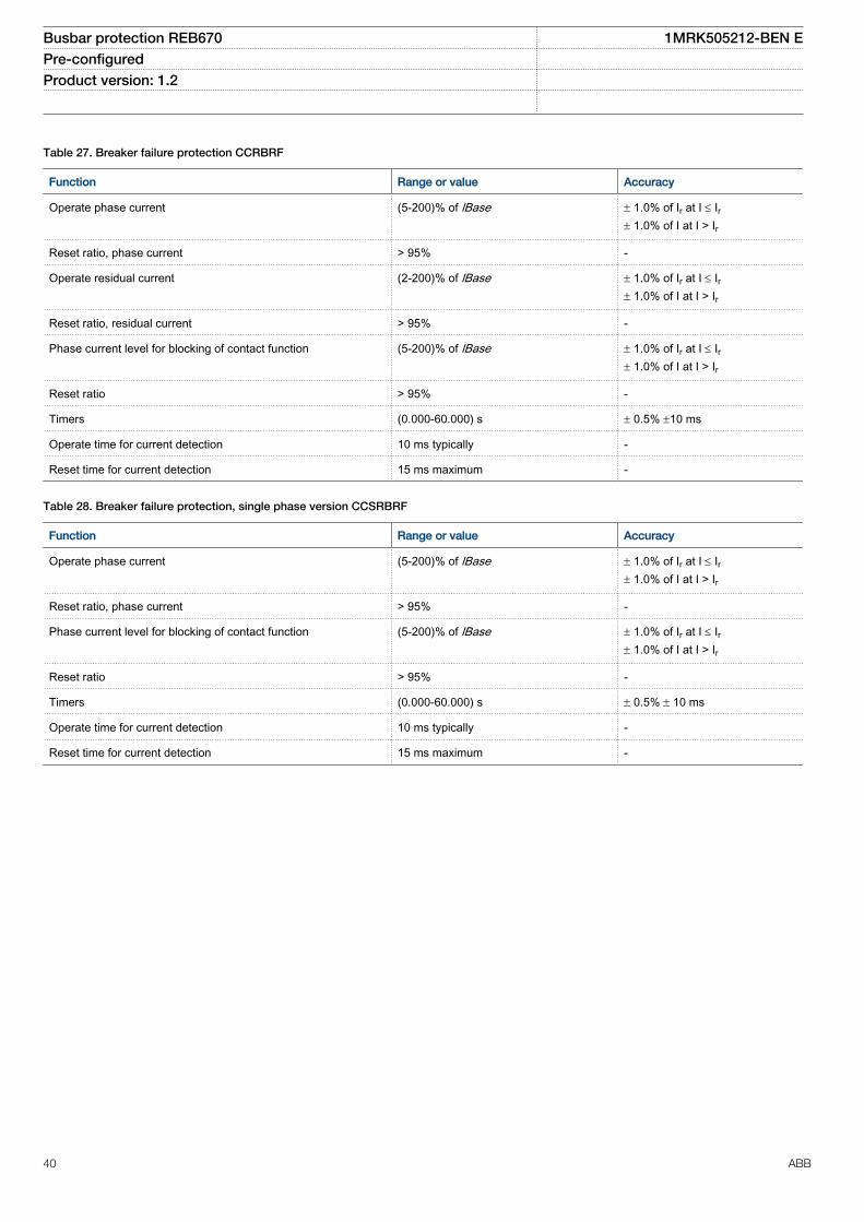
Table 27. Breaker failure protection CCRBRF
Function Range or value Accuracy
Operate phase current (5-200)% of lBase ± 1.0% of Ir at I £ Ir± 1.0% of I at I > Ir
Reset ratio, phase current > 95% -
Operate residual current (2-200)% of lBase ± 1.0% of Ir at I £ Ir± 1.0% of I at I > Ir
Reset ratio, residual current > 95% -
Phase current level for blocking of contact function (5-200)% of lBase ± 1.0% of Ir at I £ Ir± 1.0% of I at I > Ir
Reset ratio > 95% -
Timers (0.000-60.000) s ± 0.5% ±10 ms
Operate time for current detection 10 ms typically -
Reset time for current detection 15 ms maximum -
Table 28. Breaker failure protection, single phase version CCSRBRF
Function Range or value Accuracy
Operate phase current (5-200)% of lBase ± 1.0% of Ir at I £ Ir± 1.0% of I at I > Ir
Reset ratio, phase current > 95% -
Phase current level for blocking of contact function (5-200)% of lBase ± 1.0% of Ir at I £ Ir± 1.0% of I at I > Ir
Reset ratio > 95% -
Timers (0.000-60.000) s ± 0.5% ± 10 ms
Operate time for current detection 10 ms typically -
Reset time for current detection 15 ms maximum -
Busbar protection REB670 1MRK505212-BEN EPre-configured Product version: 1.2
40 ABB

Control
Table 29. Autorecloser SMBRREC
Function Range or value Accuracy
Number of autoreclosing shots 1 - 5 -
Autoreclosing open time:shot 1 - t1 1Phshot 1 - t1 2Phshot 1 - t1 3PhHSshot 1 - t1 3PhDld
(0.000-60.000) s
± 0.5% ± 10 ms
shot 2 - t2shot 3 - t3shot 4 - t4shot 5 - t5
(0.00-6000.00) s
Extended autorecloser open time (0.000-60.000) s
Autorecloser maximum wait time for sync (0.00-6000.00) s
Maximum trip pulse duration (0.000-60.000) s
Inhibit reset time (0.000-60.000) s
Reclaim time (0.00-6000.00) s
Minimum time CB must be closed before AR becomes ready for autoreclosing cycle (0.00-6000.00) s
Circuit breaker closing pulse length (0.000-60.000) s
CB check time before unsuccessful (0.00-6000.00) s
Wait for master release (0.00-6000.00) s
Wait time after close command before proceeding to next shot (0.000-60.000) s
Busbar protection REB670 1MRK505212-BEN EPre-configured Product version: 1.2
ABB 41

Logic
Table 30. Configurable logic blocks
Logic block Quantity with update rate Range or value Accuracy
fast medium normal
LogicAND 90 90 100 - -
LogicOR 90 90 100 - -
LogicXOR 15 15 10 - -
LogicInverter 45 45 50 - -
LogicSRMemory 15 15 10 - -
LogicRSMemory 15 15 10 - -
LogicGate 15 15 10 - -
LogicTimer 15 15 10 (0.000–90000.000) s ± 0.5% ± 10 ms
LogicPulseTimer 15 15 10 (0.000–90000.000) s ± 0.5% ± 10 ms
LogicTimerSet 15 15 10 (0.000–90000.000) s ± 0.5% ± 10 ms
LogicLoopDelay 15 15 10 (0.000–90000.000) s ± 0.5% ± 10 ms
Boolean 16 to Integer 4 4 8 - -
Boolean 16 to integerwith Logic Node
4 4 8 - -
Integer to Boolean 16 4 4 8 - -
Integer to Boolean 16with Logic Node
4 4 8 - -
Busbar protection REB670 1MRK505212-BEN EPre-configured Product version: 1.2
42 ABB
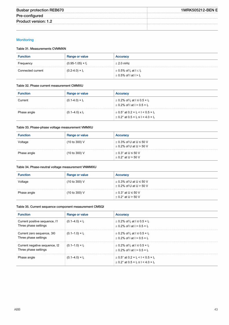
Monitoring
Table 31. Measurements CVMMXN
Function Range or value Accuracy
Frequency (0.95-1.05) × fr ± 2.0 mHz
Connected current (0.2-4.0) × Ir ± 0.5% of Ir at I £ Ir± 0.5% of I at I > Ir
Table 32. Phase current measurement CMMXU
Function Range or value Accuracy
Current (0.1-4.0) × Ir ± 0.2% of Ir at I ≤ 0.5 × Ir± 0.2% of I at I > 0.5 × Ir
Phase angle (0.1–4.0) x Ir ± 0.5° at 0.2 × Ir < I < 0.5 × Ir± 0.2° at 0.5 × Ir ≤ I < 4.0 × Ir
Table 33. Phase-phase voltage measurement VMMXU
Function Range or value Accuracy
Voltage (10 to 300) V ± 0.3% of U at U ≤ 50 V± 0.2% of U at U > 50 V
Phase angle (10 to 300) V ± 0.3° at U ≤ 50 V± 0.2° at U > 50 V
Table 34. Phase-neutral voltage measurement VNMMXU
Function Range or value Accuracy
Voltage (10 to 300) V ± 0.3% of U at U ≤ 50 V± 0.2% of U at U > 50 V
Phase angle (10 to 300) V ± 0.3° at U ≤ 50 V± 0.2° at U > 50 V
Table 35. Current sequence component measurement CMSQI
Function Range or value Accuracy
Current positive sequence, I1Three phase settings
(0.1–4.0) × Ir ± 0.2% of Ir at I ≤ 0.5 × Ir± 0.2% of I at I > 0.5 × Ir
Current zero sequence, 3I0Three phase settings
(0.1–1.0) × Ir ± 0.2% of Ir at I ≤ 0.5 × Ir± 0.2% of I at I > 0.5 × Ir
Current negative sequence, I2Three phase settings
(0.1–1.0) × Ir ± 0.2% of Ir at I ≤ 0.5 × Ir± 0.2% of I at I > 0.5 × Ir
Phase angle (0.1–4.0) × Ir ± 0.5° at 0.2 × Ir < I < 0.5 × Ir± 0.2° at 0.5 × Ir ≤ I < 4.0 × Ir
Busbar protection REB670 1MRK505212-BEN EPre-configured Product version: 1.2
ABB 43

Table 36. Voltage sequence measurement VMSQI
Function Range or value Accuracy
Voltage positive sequence, U1 (10 to 300) V ± 0.3% of U at U ≤ 50 V± 0.2% of U at U > 50 V
Voltage zero sequence, 3U0 (10 to 300) V ± 0.3% of U at U ≤ 50 V± 0.2% of U at U > 50 V
Voltage negative sequence, U2 (10 to 300) V ± 0.3% of U at U ≤ 50 V± 0.2% of U at U > 50 V
Phase angle (10 to 300) V ± 0.3° at U ≤ 50 V± 0.2° at U > 50 V
Table 37. Event counter CNTGGIO
Function Range or value Accuracy
Counter value 0-100000 -
Max. count up speed 10 pulses/s (50% duty cycle) -
Table 38. Disturbance report DRPRDRE
Function Range or value Accuracy
Pre-fault time (0.05–9.90) s -
Post-fault time (0.1–10.0) s -
Limit time (0.5–10.0) s -
Maximum number of recordings 100, first in - first out -
Time tagging resolution 1 ms See table 59
Maximum number of analog inputs 30 + 10 (external + internallyderived)
-
Maximum number of binary inputs 96 -
Maximum number of phasors in the Trip Value recorder per recording 30 -
Maximum number of indications in a disturbance report 96 -
Maximum number of events in the Event recording per recording 150 -
Maximum number of events in the Event list 1000, first in - first out -
Maximum total recording time (3.4 s recording time and maximum number ofchannels, typical value)
340 seconds (100 recordings) at50 Hz, 280 seconds (80recordings) at 60 Hz
-
Sampling rate 1 kHz at 50 Hz1.2 kHz at 60 Hz
-
Recording bandwidth (5-300) Hz -
Table 39. Event list
Function Value
Buffer capacity Maximum number of events in the list 1000
Resolution 1 ms
Accuracy Depending on time synchronizing
Busbar protection REB670 1MRK505212-BEN EPre-configured Product version: 1.2
44 ABB

Table 40. Indications
Function Value
Buffer capacity Maximum number of indications presented for single disturbance 96
Maximum number of recorded disturbances 100
Table 41. Event recorder
Function Value
Buffer capacity Maximum number of events in disturbance report 150
Maximum number of disturbance reports 100
Resolution 1 ms
Accuracy Depending on timesynchronizing
Table 42. Trip value recorder
Function Value
Buffer capacity
Maximum number of analog inputs 30
Maximum number of disturbance reports 100
Table 43. Disturbance recorder
Function Value
Buffer capacity Maximum number of analog inputs 40
Maximum number of binary inputs 96
Maximum number of disturbance reports 100
Maximum total recording time (3.4 s recording time and maximum numberof channels, typical value)
340 seconds (100 recordings) at 50 Hz280 seconds (80 recordings) at 60 Hz
Busbar protection REB670 1MRK505212-BEN EPre-configured Product version: 1.2
ABB 45
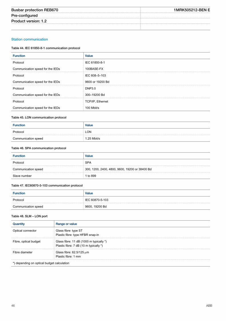
Station communication
Table 44. IEC 61850-8-1 communication protocol
Function Value
Protocol IEC 61850-8-1
Communication speed for the IEDs 100BASE-FX
Protocol IEC 608–5–103
Communication speed for the IEDs 9600 or 19200 Bd
Protocol DNP3.0
Communication speed for the IEDs 300–19200 Bd
Protocol TCP/IP, Ethernet
Communication speed for the IEDs 100 Mbit/s
Table 45. LON communication protocol
Function Value
Protocol LON
Communication speed 1.25 Mbit/s
Table 46. SPA communication protocol
Function Value
Protocol SPA
Communication speed 300, 1200, 2400, 4800, 9600, 19200 or 38400 Bd
Slave number 1 to 899
Table 47. IEC60870-5-103 communication protocol
Function Value
Protocol IEC 60870-5-103
Communication speed 9600, 19200 Bd
Table 48. SLM – LON port
Quantity Range or value
Optical connector Glass fibre: type STPlastic fibre: type HFBR snap-in
Fibre, optical budget Glass fibre: 11 dB (1000 m typically *)Plastic fibre: 7 dB (10 m typically *)
Fibre diameter Glass fibre: 62.5/125 mmPlastic fibre: 1 mm
*) depending on optical budget calculation
Busbar protection REB670 1MRK505212-BEN EPre-configured Product version: 1.2
46 ABB

Table 49. SLM – SPA/IEC 60870-5-103/DNP3 port
Quantity Range or value
Optical connector Glass fibre: type STPlastic fibre: type HFBR snap-in
Fibre, optical budget Glass fibre: 11 dB (3000ft/1000 m typically *)Plastic fibre: 7 dB (80ft/25 m typically *)
Fibre diameter Glass fibre: 62.5/125 mmPlastic fibre: 1 mm
*) depending on optical budget calculation
Table 50. Galvanic RS485 communication module
Quantity Range or value
Communication speed 2400–19200 bauds
External connectors RS-485 6-pole connectorSoft ground 2-pole connector
Table 51. IEC 62439-3 Edition 1 and Edition 2 parallel redundancy protocol
Function Value
Protocol IEC 61850-8-1
Communication speed 100 Base-FX
Busbar protection REB670 1MRK505212-BEN EPre-configured Product version: 1.2
ABB 47

Remote communication
Table 52. Line data communication module
Characteristic Range or value
Type of LDCM Short range (SR) Medium range (MR) Long range (LR)
Type of fibre Graded-indexmultimode62.5/125 µm or50/125 µm
Singlemode 9/125 µm Singlemode 9/125 µm
Wave length 850 nm 1310 nm 1550 nm
Optical budgetGraded-index multimode 62.5/125 mm, Graded-index multimode 50/125 mm
13 dB (typicaldistance about 3km *)9 dB (typicaldistance about 2km *)
22 dB (typicaldistance 80 km *)
26 dB (typical distance 110 km *)
Optical connector Type ST Type FC/PC Type FC/PC
Protocol C37.94 C37.94implementation **)
C37.94 implementation **)
Data transmission Synchronous Synchronous Synchronous
Transmission rate / Data rate 2 Mb/s / 64 kbit/s 2 Mb/s / 64 kbit/s 2 Mb/s / 64 kbit/s
Clock source Internal or derivedfrom receivedsignal
Internal or derivedfrom received signal
Internal or derived from receivedsignal
*) depending on optical budget calculation**) C37.94 originally defined just for multimode; using same header, configuration and data format as C37.94
Busbar protection REB670 1MRK505212-BEN EPre-configured Product version: 1.2
48 ABB
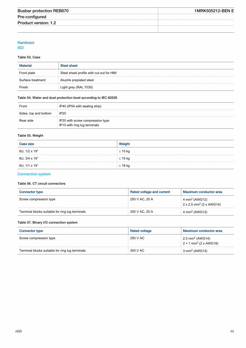
HardwareIED
Table 53. Case
Material Steel sheet
Front plate Steel sheet profile with cut-out for HMI
Surface treatment Aluzink preplated steel
Finish Light grey (RAL 7035)
Table 54. Water and dust protection level according to IEC 60529
Front IP40 (IP54 with sealing strip)
Sides, top and bottom IP20
Rear side IP20 with screw compression typeIP10 with ring lug terminals
Table 55. Weight
Case size Weight
6U, 1/2 x 19” £ 10 kg
6U, 3/4 x 19” £ 15 kg
6U, 1/1 x 19” £ 18 kg
Connection system
Table 56. CT circuit connectors
Connector type Rated voltage and current Maximum conductor area
Screw compression type 250 V AC, 20 A 4 mm2 (AWG12)2 x 2.5 mm2 (2 x AWG14)
Terminal blocks suitable for ring lug terminals 250 V AC, 20 A 4 mm2 (AWG12)
Table 57. Binary I/O connection system
Connector type Rated voltage Maximum conductor area
Screw compression type 250 V AC 2.5 mm2 (AWG14)2 × 1 mm2 (2 x AWG18)
Terminal blocks suitable for ring lug terminals 300 V AC 3 mm2 (AWG14)
Busbar protection REB670 1MRK505212-BEN EPre-configured Product version: 1.2
ABB 49

Basic IED functions
Table 58. Self supervision with internal event list
Data Value
Recording manner Continuous, event controlled
List size 40 events, first in-first out
Table 59. Time synchronization, time tagging
Function Value
Time tagging resolution, events and sampled measurement values 1 ms
Time tagging error with synchronization once/min (minute pulse synchronization), events and sampledmeasurement values
± 1.0 ms typically
Time tagging error with SNTP synchronization, sampled measurement values ± 1.0 ms typically
Table 60. GPS time synchronization module (GTM)
Function Range or value Accuracy
Receiver – ±1µs relative UTC
Time to reliable time reference with antenna in newposition or after power loss longer than 1 month
<30 minutes –
Time to reliable time reference after a power losslonger than 48 hours
<15 minutes –
Time to reliable time reference after a power lossshorter than 48 hours
<5 minutes –
Table 61. GPS – Antenna and cable
Function Value
Max antenna cable attenuation 26 db @ 1.6 GHz
Antenna cable impedance 50 ohm
Lightning protection Must be provided externally
Antenna cable connector SMA in receiver endTNC in antenna end
Accuracy +/-2μs
Busbar protection REB670 1MRK505212-BEN EPre-configured Product version: 1.2
50 ABB

Table 62. IRIG-B
Quantity Rated value
Number of channels IRIG-B 1
Number of channels PPS 1
Electrical connector:
Electrical connector IRIG-B BNC
Pulse-width modulated 5 Vpp
Amplitude modulated– low level– high level
1-3 Vpp3 x low level, max 9 Vpp
Supported formats IRIG-B 00x, IRIG-B 12x
Accuracy +/-10μs for IRIG-B 00x and +/-100μs for IRIG-B 12x
Input impedance 100 k ohm
Optical connector:
Optical connector PPS and IRIG-B Type ST
Type of fibre 62.5/125 μm multimode fibre
Supported formats IRIG-B 00x, PPS
Accuracy +/- 2μs
Busbar protection REB670 1MRK505212-BEN EPre-configured Product version: 1.2
ABB 51

Inverse characteristic
Table 63. ANSI Inverse time characteristics
Function Range or value Accuracy
Operating characteristic:
( )1= + ×
-
æ öç ÷ç ÷è ø
P
At B k
I
EQUATION1249-SMALL V1 EN
Reset characteristic:
( )2 1= ×
-
trt kI
EQUATION1250-SMALL V1 EN
I = Imeasured/Iset
k = (0.05-999) in steps of 0.01 -
ANSI Extremely Inverse A=28.2, B=0.1217, P=2.0 , tr=29.1 ANSI/IEEE C37.112, 5%+ 40 ms
ANSI Very inverse A=19.61, B=0.491, P=2.0 , tr=21.6
ANSI Normal Inverse A=0.0086, B=0.0185, P=0.02, tr=0.46
ANSI Moderately Inverse A=0.0515, B=0.1140, P=0.02, tr=4.85
ANSI Long Time Extremely Inverse A=64.07, B=0.250, P=2.0, tr=30
ANSI Long Time Very Inverse A=28.55, B=0.712, P=2.0, tr=13.46
ANSI Long Time Inverse A=0.086, B=0.185, P=0.02, tr=4.6
Busbar protection REB670 1MRK505212-BEN EPre-configured Product version: 1.2
52 ABB

Table 64. IEC Inverse time characteristics
Function Range or value Accuracy
Operating characteristic:
( )1= ×
-
æ öç ÷ç ÷è ø
P
At k
I
EQUATION1251-SMALL V1 EN
I = Imeasured/Iset
k = (0.05-999) in steps of 0.01 -
Time delay to reset, IEC inverse time (0.000-60.000) s ± 0.5% of set time ± 10 ms
IEC Normal Inverse A=0.14, P=0.02 IEC 60255-151, 5% + 40ms
IEC Very inverse A=13.5, P=1.0
IEC Inverse A=0.14, P=0.02
IEC Extremely inverse A=80.0, P=2.0
IEC Short time inverse A=0.05, P=0.04
IEC Long time inverse A=120, P=1.0
Programmable characteristicOperate characteristic:
( )= + ×
-
æ öç ÷ç ÷è ø
P
At B k
I C
EQUATION1370-SMALL V1 EN
Reset characteristic:
( )= ×
-PR
TRt k
I CR
EQUATION1253-SMALL V1 EN
I = Imeasured/Iset
k = (0.05-999) in steps of 0.01A=(0.005-200.000) in steps of 0.001B=(0.00-20.00) in steps of 0.01C=(0.1-10.0) in steps of 0.1P=(0.005-3.000) in steps of 0.001TR=(0.005-100.000) in steps of 0.001CR=(0.1-10.0) in steps of 0.1PR=(0.005-3.000) in steps of 0.001
Table 65. RI and RD type inverse time characteristics
Function Range or value Accuracy
RI type inverse characteristic
1
0.2360.339
= ×
-
t k
IEQUATION1137-SMALL V1 EN
I = Imeasured/Iset
k = (0.05-999) in steps of 0.01 IEC 60255-151, 5% + 40ms
RD type logarithmic inverse characteristic
5.8 1.35= - ×æ öç ÷è ø
tI
Ink
EQUATION1138-SMALL V1 EN
I = Imeasured/Iset
k = (0.05-999) in steps of 0.01
Busbar protection REB670 1MRK505212-BEN EPre-configured Product version: 1.2
ABB 53

16. Ordering
GuidelinesCarefully read and follow the set of rules to ensure problem-free order management.Please refer to the available functions table for included application functions.PCM600 can be used to make changes and/or additions to the delivered factory configuration of the pre-configured.
To obtain the complete ordering code, please combine code from the tables, as given in the example below.Example code: REB670*1.2-A20X01-C06-X0-A-A-B-A-A2-X0-CAX-XXX-XD. Using the code of each position #1-12 specified as REB670*1-2 2-3 3 3-4-5-6-7 7-8-9 99-10 10 10 10 10 10 10 10 10 10 10-11 11 11 11 11 11-12 12
# 1 - 2 - 3 - 4 - 5 6 - 7 - 8 - 9 -REB670* - - - - - . - -
10 - 11 - 12 . -
Po
sitio
n
SOFTWARE #1 Notes and Rules
Version number Version no 1.2
Selection for position #1.
Configuration alternatives #2 Notes and Rules
3 phase, 4 bays A20 3 phase, 8 bays A31 1 phase, 12 bays, 1/2 19" case B20 1 phase, 12 bays, 1/1 19" case B21 1 phase, 24 bays B31 ACT configuration Simple station layout, 1 1/2 CB, 2 CB, 1 CB, b-contacts, BBP only X01 Double busbar - 1 CB, a and b contacts, BBP only X02 Note: Only for A31, B21 and B31 Double busbar - 1 CB, a and b contacts, BBP, EnFP X03 Note: Only for A31, B21 and B31
Note: One each of Breaker failureprotection and Overcurrentprotection must be ordered
Selection for position #2.
Software options #3 Notes and Rules
No option X00 All fields in the ordering form donot need to be filled in
Four step phase overcurrent protection, 4 bays C06 Note: Only for A20 Four step phase overcurrent protection, 8 bays C07 Note: Only for A31 Four step single phase overcurrent protection, 12 bays C08 Note: Only for B20 and B21 Four step single phase overcurrent protection, 24 bays C09 Note: Only for B31 Breaker failure protection, 4 bays C10 Note: Only for A20 Breaker failure protection, 8 bays C11 Note: Only for A31 Breaker failure protection, 12 bays, single phase C12 Note: Only for B20 and B21 Breaker failure protection, 24 bays, single phase C13 Note: Only for B31 Autorecloser, 2 circuit breakers H05 IEC 62439-3 Edition 1, parallel redundancy protocol P01 Note:Require 2-channel OEM IEC 62439-3 Edition 2, parallel redundancy protocol P02 Selection for position #3
Busbar protection REB670 1MRK505212-BEN EPre-configured Product version: 1.2
54 ABB

First local HMI user dialogue language #4 Notes and Rules
HMI language, English IEC B1 HMI language, English US B2 Additional local HMI user dialogue language HMI language, German A1 HMI language, Russian A2 HMI language, French A3 HMI language, Spanish A4 HMI language, Polish A6 HMI language, Hungarian A7 HMI language, Czech A8 HMI language, Swedish A9 Selection for position #4.
Casing #5 Notes and Rules
1/2 x 19" case A Note: Only for A20/B20 3/4 x 19" case 1 TRM B Note: Only for A20/B20 1/1 x 19" case 2 TRM slots E Note: Only for A31/B21/B31 Selection for position #5.
Mounting details with IP40 of protection from the front #6 Notes and Rules
No mounting kit included X 19" rack mounting kit for 1/2 x 19" case of 2xRHGS6 or RHGS12 A Note: Only for A20/B20 19" rack mounting kit for 3/4 x 19" case or 3xRGHS6 B Note: Only for A20/B20 19" rack mounting kit for 1/1 x 19" case C Wall mounting kit D Note: Wall mounting not
recommended withcommunication modules withfibre connection (SLM, OEM,LDCM)
Flush mounting kit E Flush mounting kit + IP54 mounting seal F Selection for position #6.
Connection type for Power supply, Input/output and Communication modules #7 Notes and Rules
Compression terminals K Auxiliary power supply 24-60 VDC A 90-250 VDC B Selection for position #7.
Human machine hardware interface #8 Notes and Rules
Small size - text only, IEC keypad symbols A Medium size - graphic display, IEC keypad symbols B Medium size - graphic display, ANSI keypad symbols C Selection for position #8.
Connection type for Analog modules #9 Notes and Rules
Compression terminals A Ringlug terminals B Analog system First TRM, 12I, 1A 1 First TRM, 12I, 5A 2 No second TRM included X0 Note: A31/B31 must include a
second TRM, optional in B21 Second TRM, 12I, 1A 1 Second TRM, 12I, 5A 2 Selection for position #9.
Busbar protection REB670 1MRK505212-BEN EPre-configured Product version: 1.2
ABB 55

Binary input/output module, mA and time synchronizationboards. Note: 1BIM and 1 BOM included.
#10 Notes and Rules
Make BIM with 50 mA inrush current the primary choice. BIM with 50 mA inrush current fulfill additional standards. As a consequence the EMC withstandcapability is further increased.BIM with 30 mA inrush current is still available.For pulse counting, for example kWh metering, the BIM with enhanced pulse counting capabilities must be used.
Slot position (rear view)
X31
X41
X51
X61
X71
X81
X91
X101
X111
X121
X131 Note: Max 3 positions in 1/2 rack,
8 in 3/4 rack with 1 TRM and 11in 1/1 rack with 2 TRM
1/2 Case with 1 TRM █ █ █ Note: Only for A20/B20. Onlyposition X31 to X51 can beselected
3/4 Case with 1 TRM █ █ █ █ █ █ █ █ Note: Only for A20/B201/1 Case with 2 TRM █ █ █ █ █ █ █ █ █ █ █ Note: Only for A31/B21/B31 No board in slot X X X X X X X X X Note: * Not in B21/B31 Binary output module 24 output relays (BOM) A A A A A A A A A A Note: Maximum 4 BOM+SOM
boardsNote: Basic configuration in A20,A31 and B20 adapted for 1 BIMand 1 BOMNote: Basic configuration in B21and B31 adapted for 2 BIM and 1BOM
BIM 16 inputs, RL24-30 VDC, 30 mA B B B B B B B B B B BIM 16 inputs, RL48-60 VDC, 30 mA C C C C C C C C C C BIM 16 inputs, RL110-125 VDC, 30 mA D D D D D D D D D D BIM 16 inputs, RL220-250 VDC, 30 mA E E E E E E E E E E
BIM 16 inputs, RL24-30 VDC, 50 mA B1
B1 B1
B1
B1
B1
B1
B1
B1
B1
BIM 16 inputs, RL48-60 VDC, 50 mA C1
C1 C1
C1
C1
C1
C1
C1
C1
C1
BIM 16 inputs, RL110-125 VDC, 50 mA D1
D1 D1
D1
D1
D1
D1
D1
D1
D1
BIM 16 inputs, RL220-250 VDC, 50 mA E1
E1 E1
E1
E1
E1
E1
E1
E1
E1
BIMp 16 inputs, RL24-30 VDC for pulse counting F* F F F F F F F F BIMp 16 inputs, RL48-60 VDC for pulse counting G* G G G G G G G G BIMp 16 inputs, RL110-125 VDC for pulse counting H* H H H H H H H H BIMp 16 inputs, RL220-250 VDC for pulse counting K* K K K K K K K K IOM 8 inputs, 10+2 output, RL24-30 VDC L* L L L L L L L L IOM 8 inputs, 10+2 output, RL48-60 VDC M* M M M M M M M M IOM 8 inputs, 10+2 output, RL110-125 VDC N* N N N N N N N N IOM 8 inputs, 10+2 output, RL220-250 VDC P* P P P P P P P P IOM 8 inputs, 10+2 output, RL24-30 VDC, 50 mA L1* L1 L1 L1 L1 L1 L1 L1 L1 IOM 8 inputs, 10+2 output, RL48-60 VDC, 50 mA M1* M
1M1
M1
M1
M1
M1
M1
M1
IOM 8 inputs, 10+2 output, RL110-125 VDC, 50 mA N1* N1
N1
N1
N1
N1
N1
N1
N1
IOM 8 inputs, 10+2 output, RL220-250 VDC, 50 mA P1* P1
P1
P1
P1
P1
P1
P1
P1
IOM with MOV 8 inputs, 10-2 output, 24-30 VDC U* U U U U U U U U IOM with MOV 8 inputs, 10-2 output, 48-60 VDC V* V V V V V V V V IOM with MOV 8 inputs, 10-2 output, 110-125 VDC W* W W W W W W W W IOM with MOV 8 inputs, 10-2 output, 220-250 VDC Y* Y Y Y Y Y Y Y Y mA input module MIM, 6 channels R* R R R R R R R R Note: No MIM board in 1/2 case SOM Static outputs module, 12 outputs, 48-60 VDC T1* T1 T1 T1 T1 T1 T1 T1 T1 SOM static outputs module, 12 outputs, 110-250 VDC T2* T2 T2 T2 T2 T2 T2 T2 T2
Selection for position #10.
Busbar protection REB670 1MRK505212-BEN EPre-configured Product version: 1.2
56 ABB

Remote end communication, DNP serial comm. and time synchronization modules #11 Notes and Rules
Slot position (rear view)
X312
X313
X302
X303
X322
X323
Available slots in 1/2 case with 1 TRM █ █ █ █ Note: Max 1 LDCM Available slots in 3/4 case with 1 TRM █ █ █ █ Note: Max 2 LDCM Available slots in 1/1 case with 2 TRM slots █ █ █ █ █ █ Note: Max 2 LDCM No remote communication board included X X X X X X Optical short range SR LDCM A A A A A A GPS Time module GTM S S S S IRIG-B Time synchronization module, with PPS F Galvanic RS485 communication module G G G G G G Selection for position #11.
Serial communication unit for station communication #12 Notes and Rules
Slot position (rear view)
X301
X311
No first communication board included X No second communication board included X Serial and LON communication module (plastic) A Note: Optical ethernet module, 2
channel glass is not allowedtogether with SLM. Serial (plastic) and LON (glass) communication module B
Serial and LON communication module (glass) C Serial IEC 60870-5-103 plastic interface F Serial IEC 60870-5-103 plastic/glass interface G Serial IEC 60870-5-103 glass interface H Optical ethernet module, 1 channel glass D Optical ethernet module, 2 channel glass E Selection for position #12.
Guidelines
Carefully read and follow the set of rules to ensure problem-free order management. Be aware that certain functions can only be ordered incombination with other functions and that some functions require specific hardware selections.
Please refer to the available functions table for included application functions.
AccessoriesExternal current transformer unit
Note: Only for REB670 B20, B21 and B31
3 pcs SLCE 8–1 summation transformers on apparatus plate (2U high), 1/1 A Quantity: 1MRK 000 643-EA
3 pcs SLCE 8–1 summation transformers on apparatus plate (2U high), 5/1 A Quantity: 1MRK 000 643-FA
3 pcs SLCE 8–1 summation transformers on apparatus plate (2U high), 2/1 A Quantity: 1MRK 000 643-GA
GPS antenna and mounting details
GPS antenna, including mounting kits Quantity: 1MRK 001 640-AA
Cable for antenna, 20 m Quantity: 1MRK 001 665-AA
Cable for antenna, 40 m Quantity: 1MRK 001 665-BA
Busbar protection REB670 1MRK505212-BEN EPre-configured Product version: 1.2
ABB 57

Interface converter (for remote end data communication)
External interface converter from C37.94 to G703 Quantity: 1 2 1MRK 002 245-AA
External interface converter from C37.94 to G703.E1 Quantity: 1 2 1MRK 002 245-BA
Test switchThe test system COMBITEST intended for use with the IED670 products is described in 1MRK 512 001-BEN and 1MRK001024-CA. Please refer to the website:www.abb.com/substationautomation for detailed information.
Due to the high flexibility of our product and the wide varietyof applications possible the test switches needs to beselected for each specific application.
Select your suitable test switch based on the availablecontacts arrangements shown in the referencedocumentation.
However our proposals for suitable variants are:
RK926 315-AV is provided with one three-phase CT inputwith current shorting and with sixteen trip output blocking
contacts. It is suitable when external CT grounding is requiredboth for the three-phase version and single-phase versions.One such switch is then used per bay. With sucharrangement the best possible test facilities for BBP &integrated BFP are available
Test switches type RTXP 24 is ordered separately. Pleaserefer to Section "Related documents" for reference tocorresponding documents.
RHGS 6 Case or RHGS 12 Case with mounted RTXP 24 andthe on/off switch for dc-supply are ordered separately. Pleaserefer to Section "Related documents" for reference tocorresponding documents.
Protection cover
Protective cover for rear side of RHGS6, 6U, 1/4 x 19” Quantity: 1MRK 002 420-AE
Protective cover for rear side of terminal, 6U, 1/2 x 19” Quantity: 1MRK 002 420-AC
Protective cover for rear side of terminal, 6U, 3/4 x 19” Quantity: 1MRK 002 420-AB
Protective cover for rear side of terminal, 6U, 1/1 x 19” Quantity: 1MRK 002 420-AA
Combiflex
Key switch for settings
Key switch for lock-out of settings via LCD-HMI Quantity: 1MRK 000 611-A
Note: To connect the key switch, leads with 10 A Combiflex socket on one end must be used.
Side-by-side mounting kit Quantity: 1MRK 002 420-Z
Configuration and monitoring tools
Front connection cable between LCD-HMI and PC Quantity: 1MRK 001 665-CA
Busbar protection REB670 1MRK505212-BEN EPre-configured Product version: 1.2
58 ABB
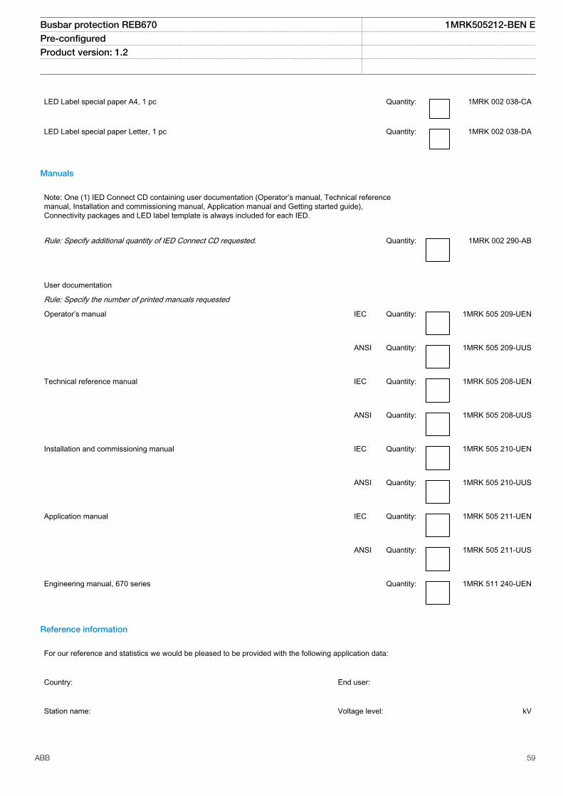
LED Label special paper A4, 1 pc Quantity: 1MRK 002 038-CA
LED Label special paper Letter, 1 pc Quantity: 1MRK 002 038-DA
Manuals
Note: One (1) IED Connect CD containing user documentation (Operator’s manual, Technical referencemanual, Installation and commissioning manual, Application manual and Getting started guide),Connectivity packages and LED label template is always included for each IED.
Rule: Specify additional quantity of IED Connect CD requested. Quantity: 1MRK 002 290-AB
User documentation
Rule: Specify the number of printed manuals requested
Operator’s manual IEC Quantity: 1MRK 505 209-UEN
ANSI Quantity: 1MRK 505 209-UUS
Technical reference manual IEC Quantity: 1MRK 505 208-UEN
ANSI Quantity: 1MRK 505 208-UUS
Installation and commissioning manual IEC Quantity: 1MRK 505 210-UEN
ANSI Quantity: 1MRK 505 210-UUS
Application manual IEC Quantity: 1MRK 505 211-UEN
ANSI Quantity: 1MRK 505 211-UUS
Engineering manual, 670 series Quantity: 1MRK 511 240-UEN
Reference information
For our reference and statistics we would be pleased to be provided with the following application data:
Country: End user:
Station name: Voltage level: kV
Busbar protection REB670 1MRK505212-BEN EPre-configured Product version: 1.2
ABB 59

Related documents
Documents related to REB670 Identity number
Operator’s manual 1MRK 505 209-UEN
Installation and commissioning manual 1MRK 505 210-UEN
Technical reference manual 1MRK 505 208-UEN
Application manual 1MRK 505 211-UEN
Product guide pre-configured 1MRK 505 212-BEN
Connection and Installation components 1MRK 513 003-BEN
Test system, COMBITEST 1MRK 512 001-BEN
Accessories for 670 series IEDs 1MRK 514 012-BEN
670 series SPA and signal list 1MRK 500 092-WEN
IEC 61850 Data objects list for 670 series 1MRK 500 091-WEN
Engineering manual 670 series 1MRK 511 240-UEN
Communication set-up for Relion 670 series 1MRK 505 260-UEN
More information can be found on www.abb.com/substationautomation.
Busbar protection REB670 1MRK505212-BEN EPre-configured Product version: 1.2
60 ABB

61

Contact us
ABB ABSubstation Automation ProductsSE-721 59 Västerås, SwedenPhone +46 (0) 21 32 50 00Fax +46 (0) 21 14 69 18
www.abb.com/substationautomation
1MR
K50
5212
-BE
N E
© C
opyr
ight
201
2 A
BB
. All
right
s re
serv
ed.