Embed Size (px)
Citation preview
490, 491, 497, 498
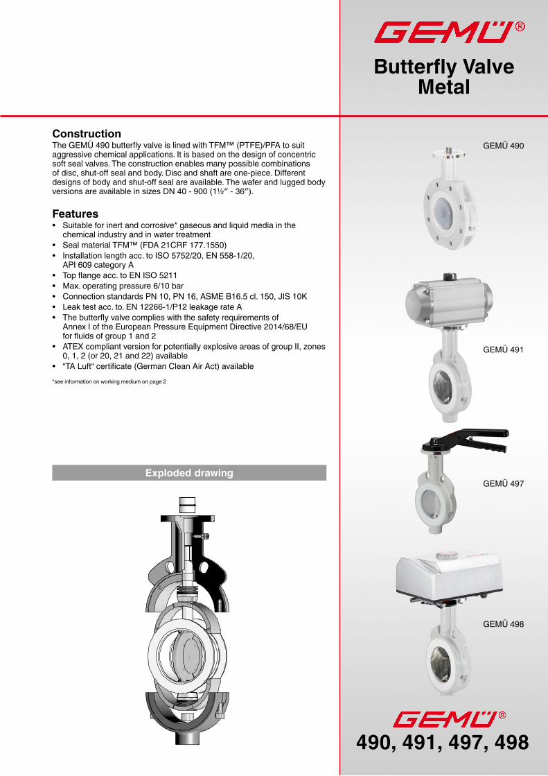
GEMÜ 490
GEMÜ 497
GEMÜ 491
GEMÜ 498
Construction The GEMÜ 490 butterfly valve is lined with TFM™ (PTFE)/PFA to suit aggressive chemical applications. It is based on the design of concentric soft seal valves. The construction enables many possible combinations of disc, shut-off seal and body. Disc and shaft are one-piece. Different designs of body and shut-off seal are available. The wafer and lugged body versions are available in sizes DN 40 - 900 (1½″ - 36″).
Features• Suitable for inert and corrosive* gaseous and liquid media in the
chemical industry and in water treatment• Seal material TFM™ (FDA 21CRF 177.1550)• Installation length acc. to ISO 5752/20, EN 558-1/20,
API 609 category A• Top flange acc. to EN ISO 5211• Max. operating pressure 6/10 bar• Connection standards PN 10, PN 16, ASME B16.5 cl. 150, JIS 10K• Leak test acc. to. EN 12266-1/P12 leakage rate A• The butterfly valve complies with the safety requirements of
Annex I of the European Pressure Equipment Directive 2014/68/EU for fluids of group 1 and 2
• ATEX compliant version for potentially explosive areas of group II, zones 0, 1, 2 (or 20, 21 and 22) available
• “TA Luft“ certificate (German Clean Air Act) available
Butterfly ValveMetal
Exploded drawing
*see information on working medium on page 2
490,491,497,4982
PTFE TFM™
TFM™PTFE
Cl ₂ (54°C)
(54°C)
SO₂ (23°C)
160320
460640
210310 cm³ / m²
day / bar
HCl
0 100 200 300 400 500 600
4
11
0 1 2 3 4 5 6 7 8 9 10 11 12%
TFM™PTFE
Technical data
Max. perm. temp. of working mediumStandard TFM™ (PTFE) -20 to 200°CNo water hammer permissible
Working mediumInert, corrosive, gaseous and liquid media which have no negative impact on the physical and chemical properties of the disc and seal material.
Advantages of the TFM™* (PTFE) shut-off sealTFM™ is manufactured from PTFE and a 1% content of perfluoropropyl vinyl ether (PPVE). While the properties of conventio-nal PTFE (excellent chemical resistance, application in a wide temperature range and resistance to embrittlement or ageing etc.) will be maintained, the PPVE additive leads to a better distribution of the PTFE particles and thus to a higher density of the molecular structure. The following extra advantages result:• Significantly better cold flow properties (measured as a deformation under load): Same cold flow properties as PTFE with
25% glass fibres.• Reduced permeability or increased blocking properties.• The smooth surface allows only slight abrasion of the shut-off seal and creates less abrasive particles in the medium.
A: Permanent deformation after cyclic load
Load: 150 bar for 100 hours, temperature 23°CPermanent deformation in %, 24 hrs after load removal
B. Permeability of various media
Permeability of TFM™ compared to conventional PTFE (thickness: 1mm)
C. Surface nature at 50x magnification
* TFM is a registered trademark of Dyneon
Connection Kv value Weight [kg]DN [m³/h] Wafer Lug40 1½″ 102 2,5 2,550 2″ 124 3 565 2½″ 211 4 780 3″ 318 5 8.1
100 4″ 660 6.3 10.8125 5″ 985 7.7 14.5150 6″ 1244 10 15.8200 8″ 2523 16.5 24.6250 10″ 3514 24.5 33.3300 12″ 5315 37 57350 14″ 8134 87* 87400 16″ 11571 107* 107450 18″ 15519 - 152500 20″ 19308 - 185600 24″ 24807 - 306700 28″ 30887 - 442
(750) 30″ 34744 - 490800 32″ 39789 - 630900 36″ 55653 - 781
1000 40″ 62690 - 946(1050) 42″ 70528 - 985 Body configuration Lug (thread holes drilled through)
Max. perm. pressure of working mediumDN 40 - 450 (1½″- 18″) 10 barDN 500 - 600 (20″- 24″) 6 barDN 700 - 1050 (28″- 42″) 3 bar
3490,491,497,498
2
4
6
8
10
0- 0,1
12
-20 180200 40 60 80 100 120 140 160 200 200-40-60-80
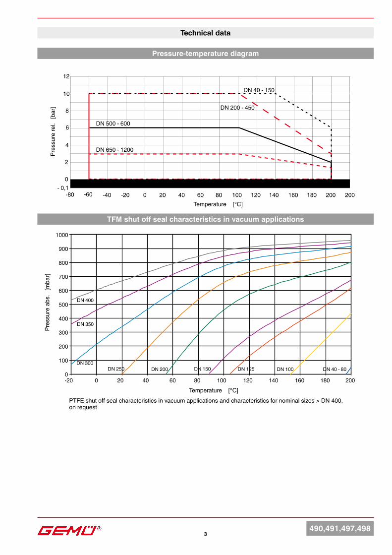
DN 650 - 1200
DN 500 - 600
DN 200 - 450
DN 40 - 150
DN 40 - 80DN 100DN 125DN 150DN 200DN 250DN 300
DN 350
0
100
200
300
400
500
600
700
800
900
1000
-20 180200 40 60 80 100 120 140 160 200
DN 400
Pressure-temperature diagram
Temperature [°C]
Pres
sure
rel.
[bar
]
Technical data
Temperature [°C]
Pres
sure
abs
. [m
bar]
Vacuum
PTFE shut off seal characteristics in vacuum applications and characteristics for nominal sizes > DN 400, on request
TFM shut off seal characteristics in vacuum applications
490,491,497,4984
Technical data
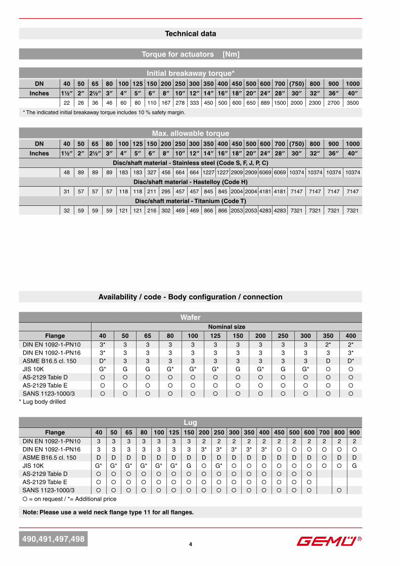
Availability / code - Body configuration / connection
WaferNominal size
Flange 40 50 65 80 100 125 150 200 250 300 350 400DIN EN 1092-1-PN10 3* 3 3 3 3 3 3 3 3 3 2* 2*DIN EN 1092-1-PN16 3* 3 3 3 3 3 3 3 3 3 3 3*ASME B16.5 cl. 150 D* 3 3 3 3 3 3 3 3 3 D D*JIS 10K G* G G G* G* G* G G* G G* ○ ○AS-2129 Table D ○ ○ ○ ○ ○ ○ ○ ○ ○ ○ ○ ○AS-2129 Table E ○ ○ ○ ○ ○ ○ ○ ○ ○ ○ ○ ○SANS 1123-1000/3 ○ ○ ○ ○ ○ ○ ○ ○ ○ ○ ○ ○
LugFlange 40 50 65 80 100 125 150 200 250 300 350 400 450 500 600 700 800 900
DIN EN 1092-1-PN10 3 3 3 3 3 3 3 2 2 2 2 2 2 2 2 2 2 2DIN EN 1092-1-PN16 3 3 3 3 3 3 3 3* 3* 3* 3* 3* ○ ○ ○ ○ ○ ○ASME B16.5 cl. 150 D D D D D D D D D D D D D D D ○ D DJIS 10K G* G* G* G* G* G* G ○ G* ○ ○ ○ ○ ○ ○ ○ ○ GAS-2129 Table D ○ ○ ○ ○ ○ ○ ○ ○ ○ ○ ○ ○ ○ ○ ○AS-2129 Table E ○ ○ ○ ○ ○ ○ ○ ○ ○ ○ ○ ○ ○ ○ ○SANS 1123-1000/3 ○ ○ ○ ○ ○ ○ ○ ○ ○ ○ ○ ○ ○ ○ ○ ○○ = on request / *= Additional price
Note: Please use a weld neck flange type 11 for all flanges.
* Lug body drilled
Torque for actuators [Nm]
Initial breakaway torque*DN 40 50 65 80 100 125 150 200 250 300 350 400 450 500 600 700 (750) 800 900 1000
Inches 1½″ 2″ 2½″ 3″ 4″ 5″ 6″ 8″ 10″ 12″ 14″ 16″ 18″ 20″ 24″ 28″ 30″ 32″ 36″ 40″22 26 36 46 60 80 110 167 278 333 450 500 600 650 889 1500 2000 2300 2700 3500
* The indicated initial breakaway torque includes 10 % safety margin.
Max. allowable torqueDN 40 50 65 80 100 125 150 200 250 300 350 400 450 500 600 700 (750) 800 900 1000
Inches 1½″ 2″ 2½″ 3″ 4″ 5″ 6″ 8″ 10″ 12″ 14″ 16″ 18″ 20″ 24″ 28″ 30″ 32″ 36″ 40″Disc/shaft material - Stainless steel (Code S, F, J, P, C)
48 89 89 89 183 183 327 456 664 664 1227 1227 2909 2909 6069 6069 10374 10374 10374 10374
Disc/shaft material - Hastelloy (Code H)31 57 57 57 118 118 211 295 457 457 845 845 2004 2004 4181 4181 7147 7147 7147 7147
Disc/shaft material - Titanium (Code T)32 59 59 59 121 121 216 302 469 469 866 866 2053 2053 4283 4283 7321 7321 7321 7321
5490,491,497,498
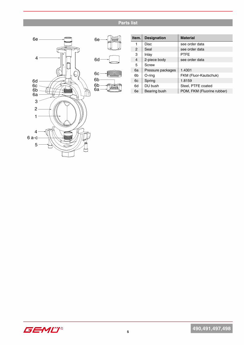
Parts list
Item. Designation Material1 Disc see order data2 Seal see order data3 Inlay PTFE4 2-piece body see order data5 Screw
6a Pressure packages 1.43016b O-ring FKM (Fluor-Kautschuk)6c Spring 1.81596d DU bush Steel, PTFE coated6e Bearing bush POM, FKM (Fluorine rubber)
123
4
4
5
6e
6d6c6b 6a
6c
6d
6b
6e
6b
6a
6 a-c
6490,491,497,498
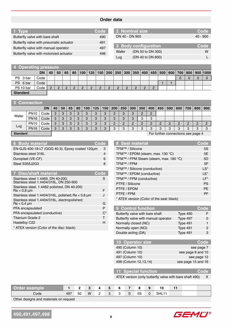
6 Body material CodeEN-GJS-400-18-LT (GGG 40.3), Epoxy coated 120µm 3Stainless steel 316L 4Duroplast (VE-CF) 6 Steel S355J2G3 8
Order data
1 Type CodeButterfly valve with bare shaft 490Butterfly valve with pneumatic actuator 491Butterfly valve with manual operator 497Butterfly valve with motorized actuator 498
11 Special function CodeATEX version (only butterfly valve with bare shaft 490) X
10 Operator size Code490 (Column 10) see page 7491 (Column 10) see page 8 and 10 497 (Column 10) see page 12498 (Column 12,13,14) see page 15 and 16
Order example 1 2 3 4 5 6 7 8 9 10 11Code 497 50 W 2 3 3 S 5S 0 SHL11
Other designs and materials on request
9 Control function CodeButterfly valve with bare shaft Type 490 FButterfly valve with manual operator Type 497 0Normally closed (NC) Type 491 1Normally open (NO) Type 491 2Double acting (DA) Type 491 3
3 Body configuration CodeWafer (DN 50 to DN 300) WLug (DN 40 to DN 800) L
5 ConnectionDN 40 50 65 80 100 125 150 200 250 300 350 400 450 500 600 700 800 900
Wafer PN10 Code 3 3 3 3 3 3 3 3 3 3 2 2PN16 Code 3 3 3 3 3 3 3 3 3 3 3 3
Lug PN10 Code 3 3 3 3 3 3 3 2 2 2 2 2 2 2 2 2 2 2PN16 Code 3 3 3 3 3 3 3 3 3 3 3 3 3 3 3 3 3 3
Standard For further connections see page 4
7 Disc/shaft material CodeStainless steel 1.4469, DN 40-200; S Stainless steel 1.4404/316L, DN 250-900Stainless steel, 1.4462 polished, DN 40-200; Ra < 0,8 µm FStainless steel 1.4404/316L, polished; Ra < 0,8 µm JStainless steel 1.4404/316L, electropolished; Ra < 0,4 µm GPFA encapsulated PPFA encapsulated (conductive) C*Titanium Grade 2 THastelloy C22 H* ATEX version (Color of the disc: black)
2 Nominal size CodeDN 40 - DN 900 40 - 900
8 Seal material CodeTFM™ / Silicone 5STFM™ / EPDM (steam, max. 130 °C) 5ETFM™ / FPM Steam (steam, max. 180 °C) 5DTFM™ / FPM 5FTFM™ / Silicone (conductive) LS*TFM™ / EPDM (conductive) LE*TFM™ / FPM (conductive) LF* PTFE / Silicone PSPTFE / EPDM PEPTFE / FPM PF* ATEX version (Color of the seal: black)
4 Operating pressureDN 40 50 65 80 100 125 150 200 250 300 350 400 450 500 600 700 800 900 1000
PS 3 bar Code 0 0 0 0PS 6 bar Code 1 1PS 10 bar Code 2 2 2 2 2 2 2 2 2 2 2 2 2
Standard
H
AB
E
øa
øy
øG
øZ
IX
Y
7490,491,497,498
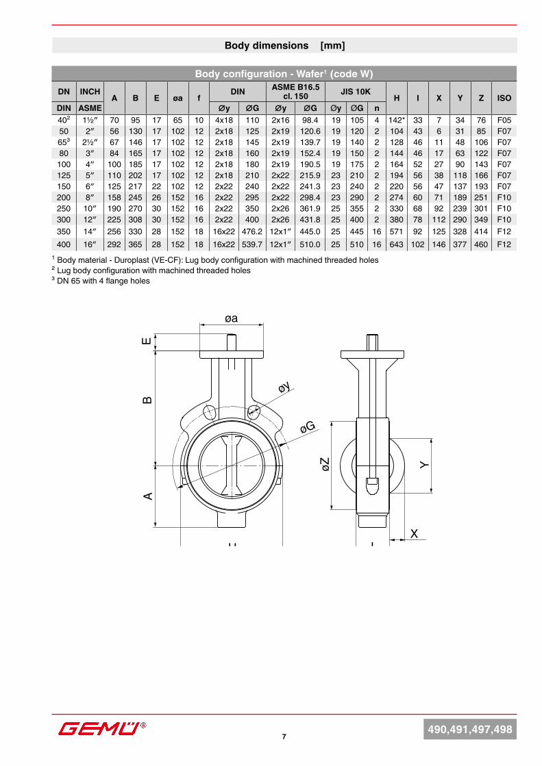
Body dimensions [mm]
1 Body material - Duroplast (VE-CF): Lug body configuration with machined threaded holes² Lug body configuration with machined threaded holes³ DN 65 with 4 flange holes
Body configuration - Wafer1 (code W)DN INCH
A B E øa fDIN ASME B16.5
cl. 150 JIS 10KH I X Y Z ISO
DIN ASME ∅y ∅G ∅y ∅G Øy ØG n40² 1½″ 70 95 17 65 10 4x18 110 2x16 98.4 19 105 4 142* 33 7 34 76 F0550 2″ 56 130 17 102 12 2x18 125 2x19 120.6 19 120 2 104 43 6 31 85 F0765³ 2½″ 67 146 17 102 12 2x18 145 2x19 139.7 19 140 2 128 46 11 48 106 F0780 3″ 84 165 17 102 12 2x18 160 2x19 152.4 19 150 2 144 46 17 63 122 F07
100 4″ 100 185 17 102 12 2x18 180 2x19 190.5 19 175 2 164 52 27 90 143 F07125 5″ 110 202 17 102 12 2x18 210 2x22 215.9 23 210 2 194 56 38 118 166 F07150 6″ 125 217 22 102 12 2x22 240 2x22 241.3 23 240 2 220 56 47 137 193 F07200 8″ 158 245 26 152 16 2x22 295 2x22 298.4 23 290 2 274 60 71 189 251 F10250 10″ 190 270 30 152 16 2x22 350 2x26 361.9 25 355 2 330 68 92 239 301 F10300 12″ 225 308 30 152 16 2x22 400 2x26 431.8 25 400 2 380 78 112 290 349 F10350 14″ 256 330 28 152 18 16x22 476.2 12x1″ 445.0 25 445 16 571 92 125 328 414 F12400 16″ 292 365 28 152 18 16x22 539.7 12x1″ 510.0 25 510 16 643 102 146 377 460 F12
8490,491,497,498
H
AB
E
øa
øy
øZ
IX
Y
øG
f
H
AB
E
øa
øy
øZ
IX
Y
øG
f
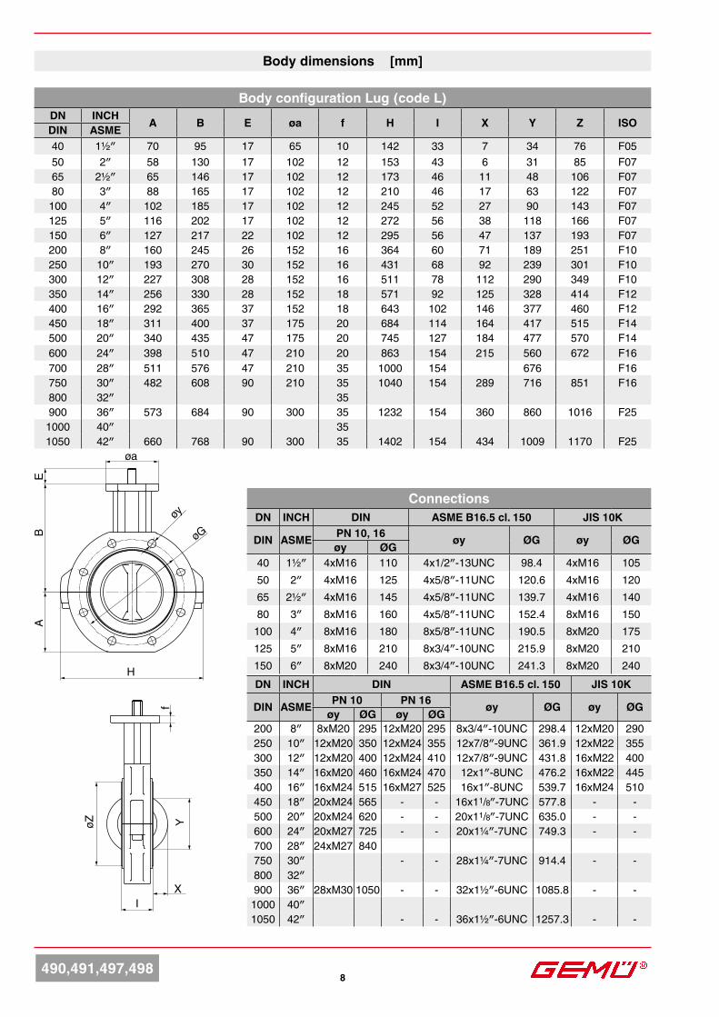
Body dimensions [mm]
Body configuration Lug (code L)DN INCH A B E øa f H I X Y Z ISODIN ASME40 1½″ 70 95 17 65 10 142 33 7 34 76 F0550 2″ 58 130 17 102 12 153 43 6 31 85 F0765 2½″ 65 146 17 102 12 173 46 11 48 106 F0780 3″ 88 165 17 102 12 210 46 17 63 122 F07
100 4″ 102 185 17 102 12 245 52 27 90 143 F07125 5″ 116 202 17 102 12 272 56 38 118 166 F07150 6″ 127 217 22 102 12 295 56 47 137 193 F07200 8″ 160 245 26 152 16 364 60 71 189 251 F10250 10″ 193 270 30 152 16 431 68 92 239 301 F10300 12″ 227 308 28 152 16 511 78 112 290 349 F10350 14″ 256 330 28 152 18 571 92 125 328 414 F12400 16″ 292 365 37 152 18 643 102 146 377 460 F12450 18″ 311 400 37 175 20 684 114 164 417 515 F14500 20″ 340 435 47 175 20 745 127 184 477 570 F14600 24″ 398 510 47 210 20 863 154 215 560 672 F16700 28″ 511 576 47 210 35 1000 154 676 F16750 30″ 482 608 90 210 35 1040 154 289 716 851 F16800 32″ 35900 36″ 573 684 90 300 35 1232 154 360 860 1016 F25
1000 40″ 351050 42″ 660 768 90 300 35 1402 154 434 1009 1170 F25
DN INCH DIN ASME B16.5 cl. 150 JIS 10K
DIN ASME PN 10 PN 16 øy ØG øy ØGøy ØG øy ØG200 8″ 8xM20 295 12xM20 295 8x3/4″-10UNC 298.4 12xM20 290250 10″ 12xM20 350 12xM24 355 12x7/8″-9UNC 361.9 12xM22 355300 12″ 12xM20 400 12xM24 410 12x7/8″-9UNC 431.8 16xM22 400350 14″ 16xM20 460 16xM24 470 12x1″-8UNC 476.2 16xM22 445400 16″ 16xM24 515 16xM27 525 16x1″-8UNC 539.7 16xM24 510450 18″ 20xM24 565 - - 16x11/8″-7UNC 577.8 - -500 20″ 20xM24 620 - - 20x11/8″-7UNC 635.0 - -600 24″ 20xM27 725 - - 20x1¼″-7UNC 749.3 - -700 28″ 24xM27 840750 30″ - - 28x1¼″-7UNC 914.4 - -800 32″900 36″ 28xM30 1050 - - 32x1½″-6UNC 1085.8 - -
1000 40″1050 42″ - - 36x1½″-6UNC 1257.3 - -
ConnectionsDN INCH DIN ASME B16.5 cl. 150 JIS 10K
DIN ASME PN 10, 16 øy ØG øy ØGøy ØG40 1½″ 4xM16 110 4x1/2″-13UNC 98.4 4xM16 10550 2″ 4xM16 125 4x5/8″-11UNC 120.6 4xM16 12065 2½″ 4xM16 145 4x5/8″-11UNC 139.7 4xM16 14080 3″ 8xM16 160 4x5/8″-11UNC 152.4 8xM16 150
100 4″ 8xM16 180 8x5/8″-11UNC 190.5 8xM20 175125 5″ 8xM16 210 8x3/4″-10UNC 215.9 8xM20 210150 6″ 8xM20 240 8x3/4″-10UNC 241.3 8xM20 240
Ø LK
Ø LxM
SW
Ø d
DN 40 - 150 DN 200 - 900Ø LK
Ø LxM
Ø dSW
C
9 490,491,497,498
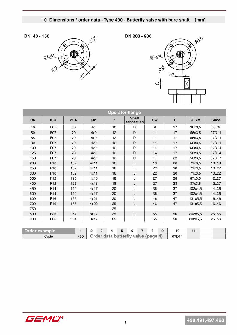
10 Dimensions / order data - Type 490 - Butterfly valve with bare shaft [mm]
Order example 1 2 3 4 5 6 7 8 9 10 11Code 490 07D11Order data butterfly valve (page 4)
Operator flangeDN ISO ØLK Ød f Shaft
connection SW C ØLxM Code
40 F05 50 4x7 10 D 9 17 36x3,5 05D950 F07 70 4x9 12 D 11 17 56x3,5 07D1165 F07 70 4x9 12 D 11 17 56x3,5 07D1180 F07 70 4x9 12 D 11 17 56x3,5 07D11
100 F07 70 4x9 12 D 14 17 56x3,5 07D14125 F07 70 4x9 12 D 14 17 56x3,5 07D14150 F07 70 4x9 12 D 17 22 56x3,5 07D17200 F10 102 4x11 16 L 19 26 71x3,5 10L19250 F10 102 4x11 16 L 22 30 71x3,5 10L22300 F10 102 4x11 16 L 22 30 71x3,5 10L22350 F12 125 4x13 18 L 27 28 87x3,5 12L27400 F12 125 4x13 18 L 27 28 87x3,5 12L27450 F14 140 4x17 20 L 36 37 102x4,5 14L36500 F14 140 4x17 20 L 36 37 102x4,5 14L36600 F16 165 4x21 20 L 46 47 131x5,5 16L46700 F16 165 4x22 35 L 46 47 131x5,5 16L46750 35800 F25 254 8x17 35 L 55 56 202x5,5 25L56900 F25 254 8x17 35 L 55 56 202x5,5 25L56
10490,491,497,498
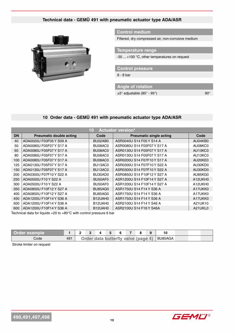
10 Order data - GEMÜ 491 with pneumatic actuator type ADA/ASR
Stroke limiter on request
Order example 1 2 3 4 5 6 7 8 9 10Code 491 BU85AGAOrder data butterfly valve (page 4)
Control mediumFiltered, dry compressed air, non-corrosive medium
Control pressure6 - 8 bar
Temperature range-30 ... +100 °C, other temperatures on request
Angle of rotation±5° adjustable (85° - 95°) 90°
Technical data - GEMÜ 491 with pneumatic actuator type ADA/ASR
10 Actuator version*DN Pneumatic double acting Code Pneumatic single acting Code40 ADA0020U F03F05 Y S09 A BU02AB0 ASR0040U S14 F05 Y S14 A AU04KB050 ADA0080U F05F07 Y S17 A BU08AC0 ASR0080U S14 F05F07 Y S17 A AU08KC065 ADA0080U F05F07 Y S17 A BU08AC0 ASR0130U S14 F05F07 Y S17 A AU13KC080 ADA0080U F05F07 Y S17 A BU08AC0 ASR0130U S14 F05F07 Y S17 A AU13KC0
100 ADA0080U F05F07 Y S17 A BU08AC0 ASR0200U S14 F07F10 Y S17 A AU20KE0125 ADA0130U F05F07 Y S17 A BU13AC0 ASR0300U S14 F07F10 Y S22 A AU30KD0150 ADA0130U F05F07 Y S17 A BU13AC0 ASR0300U S14 F07F10 Y S22 A AU30KD0200 ADA0300U F07F10 Y S22 A BU30AD0 ASR0850U S14 F10F12 Y S27 A AU85KG0250 ADA0500U F10 Y S22 A BU50AF0 ASR1200U S14 F10F14 Y S27 A A12UKH0300 ADA0500U F10 Y S22 A BU50AF0 ASR1200U S14 F10F14 Y S27 A A12UKH0350 ADA0850U F10F12 Y S27 A BU85AG0 ASR1750U S14 F14 Y S36 A A17UKK0400 ADA0850U F10F12 Y S27 A BU85AG0 ASR1750U S14 F14 Y S36 A A17UKK0450 ADA1200U F10F14 Y S36 A B12UAH0 ASR1750U S14 F14 Y S36 A A17UKK0500 ADA1200U F10F14 Y S36 A B12UAH0 ASR2100U S14 F14 Y S46 A A21UK10600 ADA1200U F10F14 Y S36 A B12UAH0 ASR2100U S14 F16 Y S46A A21UKL0
Technical data for liquids +20 to +80°C with control pressure 6 bar
D
L40 40
3015
15
ØT f8 XU
4 x M5x12
C
M6
2412 12
32
1616
M 5x12
G1/8
24 1212
321616
M 5x7,5 G1/4
ADA/ASR 00010-0850U
EB
30
44
L40 40
65 65130
XU
8 x M5x12
M6
EB
30
44
ADA 00010 ADA/ASR2100U-4000U
ADA/ASR 1200U-4000U
ØT f8
30 1515
DC
2412 12
32
1616
M 5x12
G1/4
ADA/ASR0020U-1750U
11 490,491,497,498
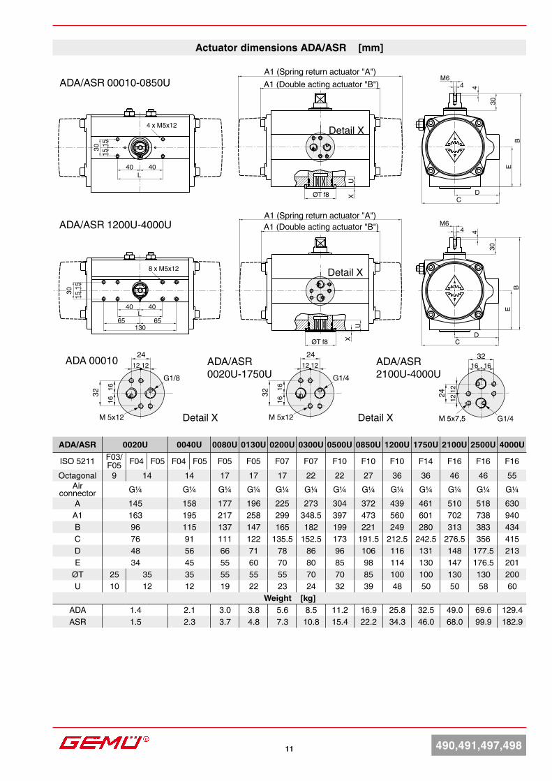
Actuator dimensions ADA/ASR [mm]
A1 (Spring return actuator "A")A1 (Double acting actuator "B")
ADA/ASR 0020U 0040U 0080U 0130U 0200U 0300U 0500U 0850U 1200U 1750U 2100U 2500U 4000U
ISO 5211 F03/ F05 F04 F05 F04 F05 F05 F05 F07 F07 F10 F10 F10 F14 F16 F16 F16
Octagonal 9 14 14 17 17 17 22 22 27 36 36 46 46 55Air
connector G¼ G¼ G¼ G¼ G¼ G¼ G¼ G¼ G¼ G¼ G¼ G¼ G¼A 145 158 177 196 225 273 304 372 439 461 510 518 630
A1 163 195 217 258 299 348.5 397 473 560 601 702 738 940B 96 115 137 147 165 182 199 221 249 280 313 383 434C 76 91 111 122 135.5 152.5 173 191.5 212.5 242.5 276.5 356 415D 48 56 66 71 78 86 96 106 116 131 148 177.5 213E 34 45 55 60 70 80 85 98 114 130 147 176.5 201
ØT 25 35 35 55 55 55 70 70 85 100 100 130 130 200U 10 12 12 19 22 23 24 32 39 48 50 50 58 60
Weight [kg]ADA 1.4 2.1 3.0 3.8 5.6 8.5 11.2 16.9 25.8 32.5 49.0 69.6 129.4ASR 1.5 2.3 3.7 4.8 7.3 10.8 15.4 22.2 34.3 46.0 68.0 99.9 182.9
A1 (Spring return actuator "A")A1 (Double acting actuator "B")
Detail X
Detail X
Detail X
Detail X
12490,491,497,498
10 Order data - GEMÜ 491 with pneumatic actuator type DR/SC*
10 Actuator sizeDN Pneumatic double acting Code Pneumatic single acting Code40 DR0015U F03F05 N S11 A DU01AW0 SC0060U 6 F05F07 N S14 A SU06KP050 DR0030U F05F07 N S14 A DU03AP0 SC0100U 6 F05F07 N S17 A SU10KC065 DR0030U F05F07 N S14 A DU06AP0 SC0100U 6 F05F07 N S17 A SU10KC080 DR0060U F05F07 N S17 A DU06AC0 SC0100U 6 F05F07 N S17 A SU10KC0
100 DR0060U F05F07 N S17 A DU06AC0 SC0150U 6 F05F07 N S17 A SU15KC0125 DR0100U F05F07 N S17 A DU10AC0 SC0220U 6 F07F10 N S22 A SU22KD0150 DR0150U F07F10 N S22 A DU15AD0 SC0300U 6 F07F10 N S22 A SU30KD0200 DR0220U F07F10 N S22 A DU22AD0 SC0450U 6 F10F12 N S27 A SU45KG0250 DR0300U F07F10 N S22 A DU30AD0 SC0900U 6 F10F12 N S27 A SU90KG0300 DR0450U F10F12 N S27 A DU45AG0 SC1200U 6 F10F12 N S27 A S12UKG0350 DR0450U F10F12 N S27 A DU45AG0 SC1200U 6 F10F12 N S27 A S12UKG0400 DR0450U F10F12 N S27 A DU45AG0 SC1200U 6 F10F12 N S27 A S12UKG0450 DR0900U F14 N S36 A DU90AK0 SC2000U 6 F14 N S36 A S20UKK0500 DR0900U F14 N S36 A DU90AK0 SC2000U 6 F14 N S36 A S20UKK0600 DR0900U F14 N S36 A DU90AK0 SC2000U 6 F16 N S46 A S20UKL0
Technical data for liquids +20 to +80°C with control pressure 6 bar
Order example 1 2 3 4 5 6 7 8 9 10Code 491 DU15AE0Order data butterfly valve (page 4)
Stroke limiter on request
Control mediumFiltered, dry compressed air, non-corrosive medium
Control pressure6 - 8 bar
Temperature range-30 ... +100 °C, other temperatures on request
Angle of rotation20° adjustable (75° - 95°) 90°
Technical data - GEMÜ 491 with pneumatic actuator type DR/SC
H
4 4 Ø40
A
M5x8M6x12
F
O
30M
ØIN
B
M5x8
32
24
hL h1
M6x10
4540
M6x10
45
40
VDI/VDE 3845
Typ 2000U-4000U
Typ 0015U-1200U
Typ 5000U
Detail Y
Luft-anschluss
'4'
Luft-anschluss
'2'
Detail X
1313 490,491,497,498
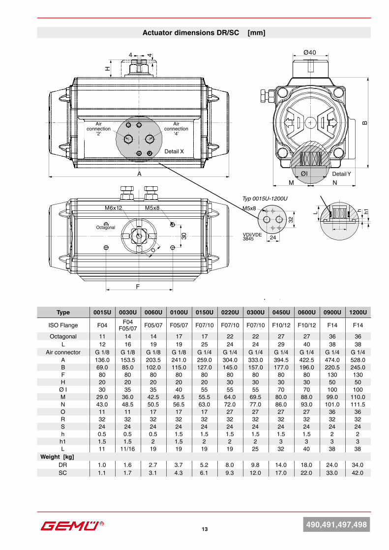
Actuator dimensions DR/SC [mm]
Type 0015U 0030U 0060U 0100U 0150U 0220U 0300U 0450U 0600U 0900U 1200U
ISO Flange F04 F04 F05/07 F05/07 F05/07 F07/10 F07/10 F07/10 F10/12 F10/12 F14 F14
Octagonal 11 14 14 17 17 22 22 27 27 36 36L 12 16 19 19 25 24 24 29 40 38 38
Air connector G 1/8 G 1/8 G 1/8 G 1/8 G 1/4 G 1/4 G 1/4 G 1/4 G 1/4 G 1/4 G 1/4A 136.0 153.5 203.5 241.0 259.0 304.0 333.0 394.5 422.5 474.0 528.0B 69.0 85.0 102.0 115.0 127.0 145.0 157.0 177.0 196.0 220.5 245.0F 80 80 80 80 80 80 80 80 80 130 130H 20 20 20 20 20 30 30 30 30 50 50
Ø I 30 35 35 40 55 55 55 70 70 100 100M 29.0 36.0 42.5 49.5 55.5 64.0 69.5 80.0 88.0 99.0 110.0N 43.0 48.5 50.5 56.5 63.0 72.0 77.0 86.0 93.0 101.0 111.5O 11 11 17 17 17 27 27 27 27 36 36R 32 32 32 32 32 32 32 32 32 32 32S 24 24 24 24 24 24 24 24 24 24 24h 0.5 0.5 0.5 1.5 1.5 1.5 1.5 1.5 1.5 2 2
h1 1.5 1.5 2 1.5 2 2 2 3 3 3 3L 11 11/16 19 19 19 19 25 32 40 38 38
Weight [kg]DR 1.0 1.6 2.7 3.7 5.2 8.0 9.8 14.0 18.0 24.0 34.0SC 1.1 1.7 3.1 4.3 6.1 9.3 12.0 17.0 22.0 33.0 42.0
Air connection
'2'
Octagonal
Air connection
'4'
490,491,497,498 14
OPEN
SHU
T30
60
B
LH
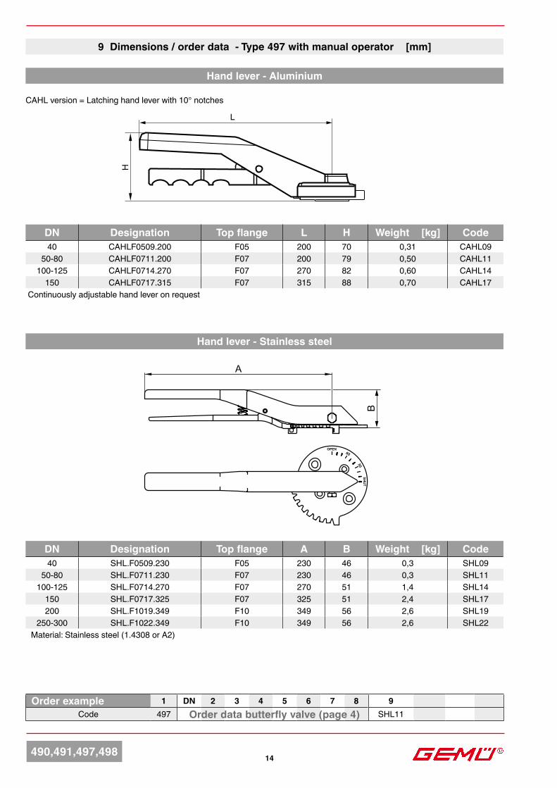
9 Dimensions / order data - Type 497 with manual operator [mm]
DN Designation Top flange A B Weight [kg] Code40 SHL.F0509.230 F05 230 46 0,3 SHL09
50-80 SHL.F0711.230 F07 230 46 0,3 SHL11100-125 SHL.F0714.270 F07 270 51 1,4 SHL14
150 SHL.F0717.325 F07 325 51 2,4 SHL17200 SHL.F1019.349 F10 349 56 2,6 SHL19
250-300 SHL.F1022.349 F10 349 56 2,6 SHL22Material: Stainless steel (1.4308 or A2)
Hand lever - Aluminium
Order example 1 DN 2 3 4 5 6 7 8 9Code 497 SHL11Order data butterfly valve (page 4)
DN Designation Top flange L H Weight [kg] Code40 CAHLF0509.200 F05 200 70 0,31 CAHL09
50-80 CAHLF0711.200 F07 200 79 0,50 CAHL11100-125 CAHLF0714.270 F07 270 82 0,60 CAHL14
150 CAHLF0717.315 F07 315 88 0,70 CAHL17 Continuously adjustable hand lever on request
Hand lever - Stainless steel
CAHL version = Latching hand lever with 10° notches
HE
ØR
B
15
CD
A
490,491,497,49815
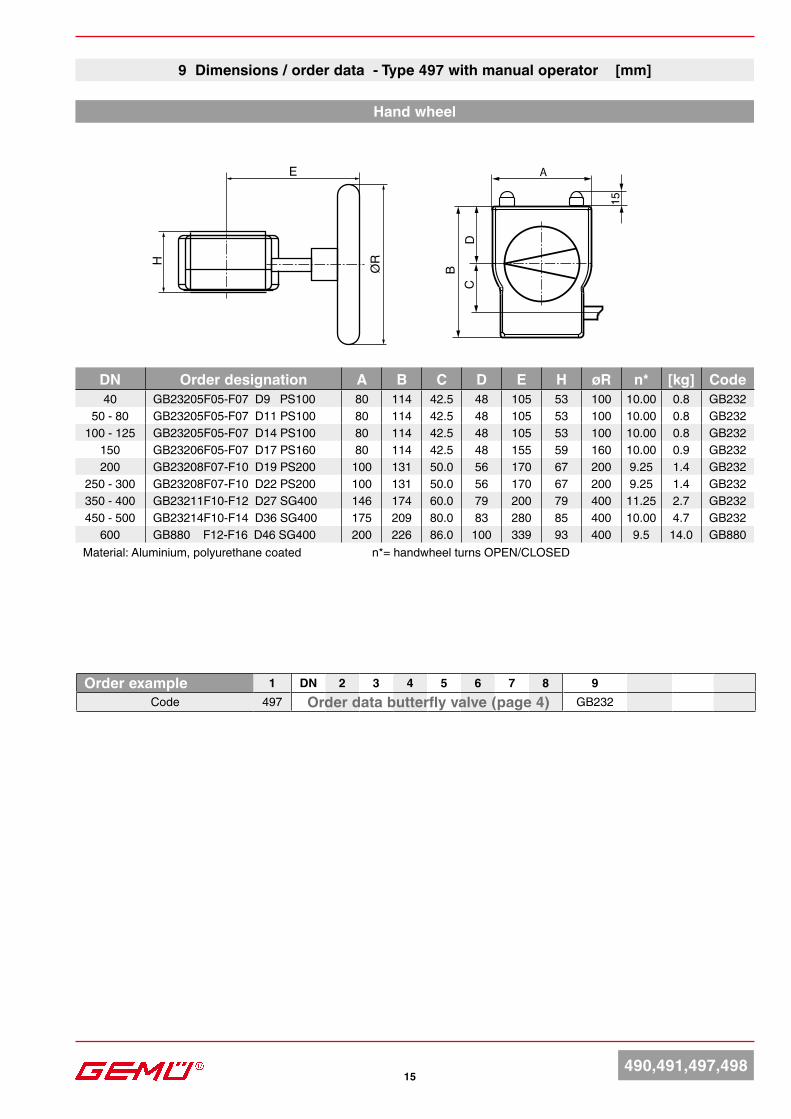
DN Order designation A B C D E H øR n* [kg] Code40 GB23205F05-F07 D9 PS100 80 114 42.5 48 105 53 100 10.00 0.8 GB232
50 - 80 GB23205F05-F07 D11 PS100 80 114 42.5 48 105 53 100 10.00 0.8 GB232100 - 125 GB23205F05-F07 D14 PS100 80 114 42.5 48 105 53 100 10.00 0.8 GB232
150 GB23206F05-F07 D17 PS160 80 114 42.5 48 155 59 160 10.00 0.9 GB232200 GB23208F07-F10 D19 PS200 100 131 50.0 56 170 67 200 9.25 1.4 GB232
250 - 300 GB23208F07-F10 D22 PS200 100 131 50.0 56 170 67 200 9.25 1.4 GB232350 - 400 GB23211F10-F12 D27 SG400 146 174 60.0 79 200 79 400 11.25 2.7 GB232450 - 500 GB23214F10-F14 D36 SG400 175 209 80.0 83 280 85 400 10.00 4.7 GB232
600 GB880 F12-F16 D46 SG400 200 226 86.0 100 339 93 400 9.5 14.0 GB880Material: Aluminium, polyurethane coated n*= handwheel turns OPEN/CLOSED
Order example 1 DN 2 3 4 5 6 7 8 9Code 497 GB232Order data butterfly valve (page 4)
9 Dimensions / order data - Type 497 with manual operator [mm]
Hand wheel
16490,491,497,498
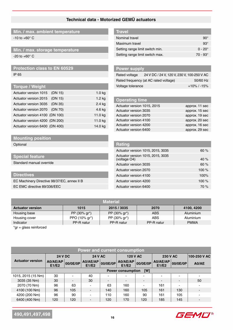
Technical data - Motorized GEMÜ actuators
Min. / max. ambient temperature-10 to +60° C
Min. / max. storage temperature-20 to +60° C
Mounting positionOptional
Special featureStandard manual override
DirectivesEC Machinery Directive 98/37/EC, annex II BEC EMC directive 89/336/EEC
TravelNominal travel 90°Maximum travel 93°Setting range limit switch min. 0 - 20°Setting range limit switch max. 70 - 93°
Protection class to EN 60529IP 65
Torque / WeightActuator version 1015 (DN 15) 1.0 kgActuator version 2015 (DN 15) 1.2 kgActuator version 3035 (DN 35) 2.4 kg Actuator version 2070 (DN 70) 4.6 kgActuator version 4100 (DN 100) 11.0 kgActuator version 4200 (DN 200) 11.0 kgActuator version 6400 (DN 400) 14.0 kg
Power supplyRated voltage 24 V DC / 24 V, 120 V, 230 V, 100-250 V ACRated frequency (at AC rated voltage) 50/60 Hz Voltage tolerance +10% / -15%
Operating timeActuator version 1015, 2015 approx. 11 secActuator version 3035 approx. 15 secActuator version 2070 approx. 19 secActuator version 4100 approx. 20 secActuator version 4200 approx. 16 secActuator version 6400 approx. 29 sec
RatingActuator version 1015, 2015, 3035 60 %Actuator version 1015, 2015, 3035 (voltage O4) 40 %Actuator version 3035 60 %Actuator version 2070 100 %Actuator version 4100 100%Actuator version 4200 100 %Actuator version 6400 70 %
MaterialActuator version 1015 2015 / 3035 2070 4100, 4200Housing base PP (30% gr*) PP (30% gr*) ABS AluminiumHousing cover PPO (10% gr*) PP (30% gr*) ABS AluminiumIndicator PP-R natur PP-R natur PP-R natur PMMA*gr = glass reinforced
Power and current consumption
Actuator version24 V DC 24 V AC 120 V AC 230 V AC 100-250 V AC
A0/AE/APE1/E2 00/0E/0P A0/AE/AP
E1/E2 00/0E/0P A0/AE/APE1/E2 00/0E/0P A0/AE/AP
E1/E2 00/0E/0P A0/AE
Power consumption [W]1015, 2015 (15 Nm) 30 - 40 - - - - - -
3035 (35 Nm) 30 - 30 - - - - - 502070 (70 Nm) 96 63 - 63 160 - 161 - -
4100 (100 Nm) 96 105 - 140 160 105 161 130 -4200 (200 Nm) 96 90 - 110 160 90 161 105 -6400 (400 Nm) 120 120 - 120 170 120 185 145 -
490,491,497,49817
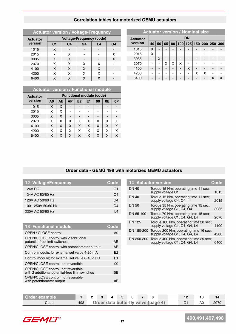
Correlation tables for motorized GEMÜ actuators
14 Actuator version CodeDN 40 Torque 15 Nm, operating time 11 sec; supply voltage C1 1015DN 40 Torque 15 Nm, operating time 11 sec; supply voltage C4, O4 2015DN 50 Torque 35 Nm, operating time 15 sec; supply voltage C1, C4, O4 3035DN 65-100 Torque 70 Nm, operating time 15 sec; supply voltage C1, C4, G4, L4 2070DN 125 Torque 100 Nm, operating time 20 sec; supply voltage C1, C4, G4, L4 4100DN 150-200 Torque 200 Nm, operating time 16 sec; supply voltage C1, C4, G4, L4 4200DN 250-300 Torque 400 Nm, operating time 29 sec; supply voltage C1, C4, G4, L4 6400
Motorized GEMÜ actuators
12 Voltage/Frequency Code 24V DC C1 24V AC 50/60 Hz C4120V AC 50/60 Hz G4100 - 250V 50/60 Hz O4230V AC 50/60 Hz L4
13 Functional module CodeOPEN / CLOSE control A0OPEN/CLOSE control with 2 additional potential-free limit switches AEOPEN/CLOSE control with potentiometer output APControl module; for external set value 4-20 mA E2Control module; for external set value 0-10V DC E1OPEN/CLOSE control, not reversible 00OPEN/CLOSE control, not reversible with 2 additional potential-free limit switches 0EOPEN/CLOSE control, not reversible with potentiometer output 0P
Order data butterfly valve (page 4)Order example 1 2 3 4 5 6 7 8 12 13 14
Code 498 C1 A0 2070Order data butterfly valve (page 4)
Order data - GEMÜ 498 with motorized GEMÜ actuators
Actuator version / Voltage-Frequency Actuator version
Voltage-Frequency (code)C1 C4 G4 L4 O4
1015 X - - - -2015 - X - - X3035 X X - - X2070 X X X X -4100 X X X X -4200 X X X X -6400 X X X X -
Actuator version / Functional moduleActuator version
Functional module (code)A0 AE AP E2 E1 00 0E 0P
1015 X X - - - - - -2015 X X - - - - - -3035 X X - - - - - -2070 X X X X X X X X4100 X X X X X X X X4200 X X X X X X X X6400 X X X X X X X X
Actuator version / Nominal sizeActuator version
DN40 50 65 80 100 125 150 200 250 300
1015 X - - - - - - - - -2015 X - - - - - - - - -3035 - X - - - - - - - -2070 - - X X X - - - - -4100 - - - - - X - - - -4200 - - - - - - X X - -6400 - - - - - - - - X X
66 76
172 208
94
B
83,5 121,540
51
155
167 235
176
107,540
4616
8 191
377
97
245104,7
207
14520
0
105277,5
131
8055C62*
14540
BA
18490,491,497,498
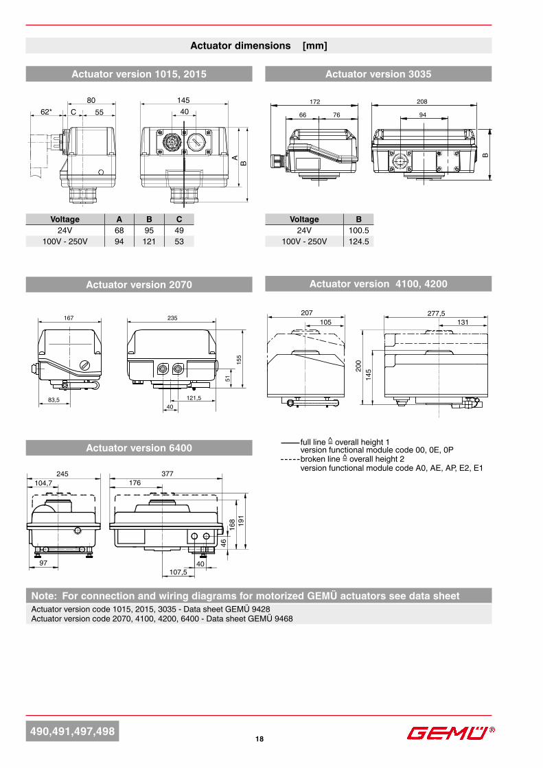
Actuator dimensions [mm]Actuator dimensions [mm]Actuator dimensions [mm]
Actuator version 2070
Voltage A B C24V 68 95 49
100V - 250V 94 121 53
Actuator version 1015, 2015 Actuator version 3035
Voltage B24V 100.5
100V - 250V 124.5
Actuator version 4100, 4200
Actuator version 6400 full line = overall height 1 version functional module code 00, 0E, 0P broken line = overall height 2 version functional module code A0, AE, AP, E2, E1
^
^
Note: For connection and wiring diagrams for motorized GEMÜ actuators see data sheetActuator version code 1015, 2015, 3035 - Data sheet GEMÜ 9428Actuator version code 2070, 4100, 4200, 6400 - Data sheet GEMÜ 9468
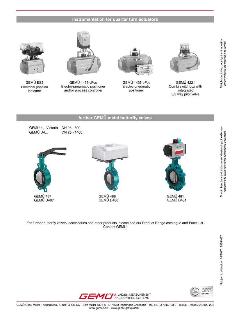
GEMÜ 4 ...Victoria
GEMÜ 481 GEMÜ D481
GEMÜ 487 GEMÜ D487
GEMÜ 488 GEMÜ D488
DN 25 - 600GEMÜ D4... DN 25 - 1400
For further butterfly valves, accessories and other products, please see our Product Range catalogue and Price List. Contact GEMÜ.
VALVES, MEASUREMENTAND CONTROL SYSTEMS
GEMÜ Gebr. Müller · Apparatebau GmbH & Co. KG · Fritz-Müller-Str. 6-8 · D-74653 Ingelfingen-Criesbach · Tel. +49 (0) 7940/123-0 · Telefax +49 (0) 7940/[email protected] · www.gemu-group.com
further GEMÜ metal butterfly valves
Instrumentation for quarter turn actuators
GEMÜ 1436 cPosElectro-pneumatic positioner
and/or process controller
GEMÜ 1435 ePosElectro-pneumatic
positioner
GEMÜ 4221Combi switchbox with
integrated 3/2 way pilot valve
GEMÜ ES2Electrical position
indicator
Subj
ect t
o al
tera
tion
· 09/
2017
· 88
3844
37Sh
ould
ther
e be
any
dou
bts o
r misu
nder
stan
ding
s, th
e G
erm
anve
rsio
n of
this
data
shee
t is th
e au
thor
itativ
e do
cum
ent!
All r
ight
s in
clud
ing
copy
right
and
indu
stria
l pr
oper
ty ri
ghts
are
exp
ress
ly re
serv
ed.


![Section 18 Butterfly Valves - AAP Industries · BUTTERFLY VALVES [18] Wafer Butterfly Valve with Gear-Op Stainless Steel Wafer Butterfly Valve Wafer Butterfly Valve with Stainless](https://img.pdfslide.net/doc/110x75/60a1925cd0b68c353a5fc104/section-18-butterfly-valves-aap-industries-butterfly-valves-18-wafer-butterfly.jpg)