Embed Size (px)
Citation preview

BWL Procedural Guideline PG-02-0002 For Generation, Transmission and End-User
Interconnection Requirements, Rev 2 FAC-001-2
Generation, Transmission, and End User Facilities
Electric System Integrity Engineering June 14, 2016
1
Contents
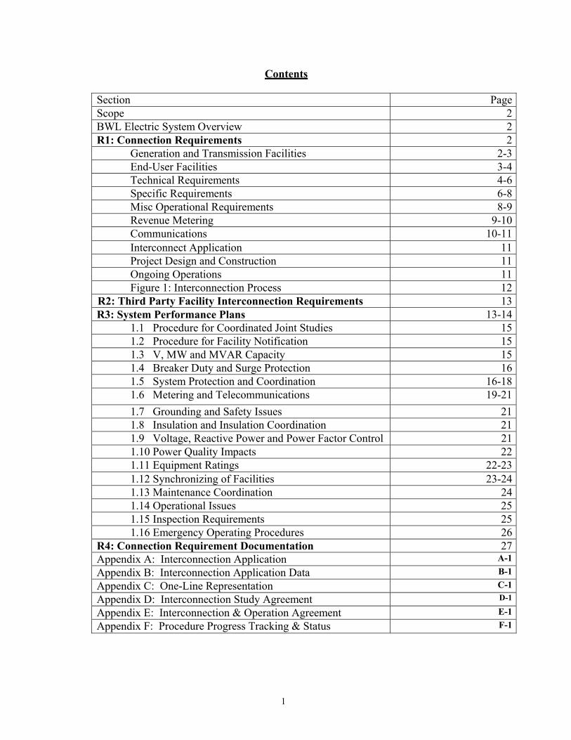
Section PageScope 2BWL Electric System Overview 2R1: Connection Requirements 2
Generation and Transmission Facilities 2-3End-User Facilities 3-4Technical Requirements 4-6Specific Requirements 6-8Misc Operational Requirements 8-9Revenue Metering 9-10Communications 10-11Interconnect Application 11Project Design and Construction 11Ongoing Operations 11Figure 1: Interconnection Process 12
R2: Third Party Facility Interconnection Requirements 13R3: System Performance Plans 13-14
1.1 Procedure for Coordinated Joint Studies 151.2 Procedure for Facility Notification 151.3 V, MW and MVAR Capacity 151.4 Breaker Duty and Surge Protection 161.5 System Protection and Coordination 16-181.6 Metering and Telecommunications 19-21
1.7 Grounding and Safety Issues 211.8 Insulation and Insulation Coordination 211.9 Voltage, Reactive Power and Power Factor Control 211.10 Power Quality Impacts 221.11 Equipment Ratings 22-231.12 Synchronizing of Facilities 23-241.13 Maintenance Coordination 241.14 Operational Issues 251.15 Inspection Requirements 251.16 Emergency Operating Procedures 26
R4: Connection Requirement Documentation 27Appendix A: Interconnection Application A-1
Appendix B: Interconnection Application Data B-1
Appendix C: One-Line Representation C-1
Appendix D: Interconnection Study Agreement D-1
Appendix E: Interconnection & Operation Agreement E-1
Appendix F: Procedure Progress Tracking & Status F-1

2
Scope This document was developed to comply with the North American Electric Reliability Council (NERC) Reliability Standard FAC-001-2, Facility Connection Requirements. Facility connection and performance requirements are established to avoid adverse impacts on reliability, meet NERC standards and to ensure that public safety is maintained. These requirements address connection requirements for Generation, Transmission and End-User facilities. BWL Electric System Overview The BWL electric system is comprised of two voltage classes, transmission and distribution. The BWL looped electric transmission system operates at 138 kV distributing bulk power supplied by the neighboring ITC 138 kV transmission system and power directly from Eckert Station and Erickson Station generators stepped up from 13.2 kV and 18.0 kV respectively. The BWL radial distribution system operates at 13.2 kV, 8.32 kV, and 4.16 kV. The 13.2 kV distribution system is supplied by BWL 138 kV transmission substations, and power directly from Eckert Station generators. The 8.32 kV and 4.16 kV distribution systems are supplied by 13.2 kV distribution substations. Each distribution feeder circuit has tie switch connections with one or more adjacent circuit feeders throughout the radial route.
R1: Connection Requirements
GENERATION AND TRANSMISSION FACILITIES
Planning and Operation The electric transmission system is used to transmit power from generation and transmission stations to step-down substations, to permit the exchange of power with neighboring transmission systems, and to accommodate inadvertent or transmission grid loop power flows that may occur due to operations of the other interconnected systems. The transmission system is designed so that reasonably foreseeable normal and contingency conditions do not result in equipment damage or loss of load in a major portion of the electric system. The looped electric transmission system is thus capable of withstanding the forced outage of any single element. The single contingency should then not result in the loss of load unless bus voltages are impacted. The BWL electric transmission system may be able to accommodate a second concurrent electric system element contingency based on relative geographic locations but is not intentionally designed to do so.
Protective Relaying The transmission system is protected by a variety of directional phase, pilot wire, and directional ground overcurrent relays. This approach allows rapid detection and isolation of faults while allowing normal loads and tolerating abnormal load dynamics with minimal effect on the overall BWL electric system.

3
Interconnection The potential hazards associated with high voltage systems and the essential need of the electric transmission system require specific work rules. These rules are to protect the public, BWL worker, and assure overall electric system operating integrity. Interconnection to the BWL electric transmission system, by way of generation or transmission facility, shall not create any safety hazards in the transmission system or detract from the safety of the existing system. Also, interconnection configurations shall consider accommodating BWL electric transmission first contingency events that may impact scheduled maintenance of the interconnected systems and the need for overall BWL electric system integrity during such maintenance.
END-USER FACILITIES Planning and Operation The electric distribution system provides electric service from the electric substation to the customer’s metering point. The high voltage part of the distribution circuit (13.2 kV, 8.32 kV, and 4.16 kV) is referred to as the “primary” and any lower voltage (commonly 480 V, 277 V, 240 V, 208 V, and 120 V) is referred to as the “secondary”. The distribution circuit is designed to provide adequate electric service to the customer in an economical and reliable manner. The BWL primary distribution circuits are three phase, four wire, grounded wye designs. The maximum design capacity of a circuit is based on industry and BWL design standards. The capacity for a 13.2 kV circuit is typically 8 MVA while 8.32 kV and 4.16 kV circuits are limited by cable size and voltage. The distribution circuit is capable of anticipated overloads of up to 125% rated load for periods not to exceed 8 hours. Distribution circuits are also designed to limit short circuit within BWL equipment ratings, meet power quality requirements, and reliability needs. Such needs are measured by the number and duration of customer interruptions. Protective Relaying The distribution system is protected by three-phase primary voltage breakers with phase and neutral overcurrent protection and reclosing relays at the substation. The phase and overcurrent relays have both inverse-time and instantaneous overcurrent elements. The reclosing relays are active on 13.2 kV overhead circuits from 138 kV transmission substations. The primary distribution circuit includes ancillary protection by a variety of three-phase pole mounted reclosers, sectionalizers and single-phase fuses and sectionalizers. The three-phase reclosers and sectionalizers are equipped with electronic controls that allow some flexibility to adjust sensitivity. The single-phase sectionalizers are designed with a specific sensitivity, as are single-phase fuses within fault interrupt ratings. Thus, single-phase protection devices must be replaced to accommodate different sensitivity or fault levels. The secondary distribution system generally relies on primary protection of the BWL equipment supplying the secondary system. Thus, the protection is typically primary single-fuses with limited fault interrupt ratings and specific sensitivity. Thus, a fault will likely interrupt all services connected to the secondary distribution system supplied by the same BWL supply equipment. Some cable-in-duct

4
secondary distribution systems are protected with fast acting current limiting cable fuses rated to interrupt within one-half cycle when current levels approach cable melt values based on cable size. The aforementioned protective devices automatically disconnect any portion of the system that faults thus minimizing the portion of the system or circuit that is isolated. The fault must not be allowed to exist for any significant period of time. The sensitivity of the protective devices must allow normal load to be served without interruption. Substation circuit reclosers are designed to reclose after automatically opening the circuit to isolate faults. Typically, the initial reclose may occur in less than a second with as many as three recloses within one minute. Interconnection The potential hazards associated with high voltage systems require specific work rules. These rules are to protect the public, BWL worker, and assure electric distribution system operating integrity. Interconnection to the BWL electric distribution system shall not create any safety hazards in the distribution system or detract from the safety of the existing system. Also, the reverse power flow conditions that generators are capable of producing must be evaluated to ensure that safety and proper coordination is not compromised. AUROA Protection The end-user is responsible for protecting his own equipment from an AUROA event. TECHNICAL REQUIREMENTS The following details present the technical requirements for interconnection of the Project. The BWL has adopted IEEE Std. 1547, Standard for Interconnecting Distributed Resources with Electric Power Systems to simplify the technical requirements. Certain requirements, as specified by this document, must be met to provide compatibility between the Project and the BWL’s electric system, and to assure that the safety and reliability of the electric system is not degraded by the interconnection. The data that the BWL requires to evaluate the proposed interconnection is documented in the appropriate Appendices. A site plan, one-line diagrams, and interconnection protection system details of the Project are required as part of the application data. The generator manufacturer supplied data package should also be included in such cases. The physically closest available system voltage, as well as equipment and operational constraints influence the chosen point of interconnection. The BWL has the ultimate authority to determine the acceptability of a particular POI. Any new line construction to connect the Project to the BWL’s electric system will be undertaken by the BWL at the Project Developer's expense. Interconnection line(s) will terminate on a termination structure provided by the Project Developer. The Project Developer is responsible for ensuring that structural material strengths are adequate for all requirements, incorporating appropriate safety factors. Upon written request, the BWL will provide line tension information for maximum dead-end tensions under heavy icing conditions. The structure must be designed for this maximum line tension along with an adequate margin of safety. Electrical clearances shall comply with requirements of the National Electrical Safety Code. The installation of

5
disconnect switches, bus support insulators, and other equipment shall comply with accepted industry practices. Regardless of the technology of the interconnection, for simplicity for all Projects, the interconnection relaying system must be certified by a nationally recognized testing laboratory to meet IEEE Std. 1547. The data submitted for review must include information from the manufacturer indicating such certification, and the manufacturer must placard the equipment such that a field inspection can verify the certification. A copy of this standard may be obtained (for a fee) from the Institute of Electrical and Electronics Engineers (www.ieee.org). The interconnection relaying design requirements are intended to assure protection of the BWL electric system. Any additional relaying which may be necessary to protect equipment at the Project is solely the responsibility of the Project Developer to determine, design, and apply. The relaying requirements will vary with the capacity rating of the Project, the type of generation being used, and the mode of operation (Flow-back or Non-Flow-back). All relaying proposed by the Project Developer to satisfy these requirements must be submitted for review and approved by the BWL. Utility grade relays are required. All relays must be equipped with targets or other visible indicators to indicate that the relay has operated. If the protective system uses AC power as the control voltage, it must be designed to disconnect the generation from the BWL electric system if the AC control power is lost. The relay system must be designed such that the Project Developer is prevented from energizing the BWL electric system when/if that system is de-energized. SEL digital relays are preferred. For situations where the Project will only be operated in parallel with the BWL’s electric system for a short duration (100 milliseconds or less), as in a make-before-break automatic transfer scheme, no additional relaying is required. Such momentary paralleling requires a modern integrated Automatic Transfer Switch (ATS) system, which is incapable of paralleling the Project with the BWL’s electric system. The ATS must be tested, verified, and documented by the Project Developer for proper operation at least every 2 years. The BWL may be present during this testing. All relaying must be connected to instrument transformers. All current connections shall be connected into current transformers (CTs). All CTs shall be rated to provide no more than 5 amperes secondary current for all normal load conditions, and must be designed for relaying use, with an “accuracy class” of at least C50. Current transformers with an accuracy class designation such as T50 are NOT acceptable. For three-phase systems, all three phases must be equipped with CTs. All potential connections must be connected into voltage transformers (VTs). For single-phase connections, the VTs shall be provided such that the secondary voltage does not exceed 120 volts for normal operations. For three-phase connections, the VTs shall be provided such that the line-to-line voltage does not exceed 120 volts for normal operation, and both the primary and secondary of the VTs shall be connected for grounded-wye connections. Direct Transfer Trip (DTT) is generally not required for Induction or Inverter-Type Projects. Direct Transfer Trip is generally not required for Synchronous Projects that will operate in the Non-Flow-back Mode since a more economic reverse power relay scheme can usually meet the requirements. For Synchronous Flowback Projects, the need for DTT is determined based on the location of the POI. The BWL requires DTT when the total generation within a protective zone is greater than 33% of the minimum BWL load that could be isolated along with the generation. This prevents sustained isolated

6
operation of the generation for conditions where Project protective relaying may not otherwise operate. Direct transfer trip adds to the cost and complexity of an interconnection. A DTT transmitter is required for each BWL protective device whose operation could result in sustained isolated operation of the Project. An associated DTT receiver at the Project is required for each DTT transmitter. A Data Circuit is required between each transmitter and receiver. Telemetry is required to monitor status of the DTT communication, even if telemetry would not otherwise have been required. At the Project Developer’s expense, the BWL will provide the receiver(s) that the Project Developer must install, and the BWL will install the transmitter(s) at the appropriate BWL protective devices. If metering for “Flow-back” Mode is not present, reverse power protection must be provided. The reverse power relaying will detect power flow from the Project into the BWL system, and operation of the reverse power relaying will separate the Project from the BWL system. The BWL employs automatic multiple-shot reclosing on most of the BWL’s circuit breakers and circuit reclosers to increase the reliability of service to its customers. The Project Developer is advised to consider the effects of Automatic Reclosing to assure that the Project’s internal equipment will not be damaged. In addition to the risk of damage to the Project, an out-of-phase reclosing operation may also present a hazard to BWL equipment since this equipment may not be rated or built to withstand this type of reclosing. To prevent out-of-phase reclosing, circuit breakers can be modified with voltage check relays. These relays block reclosing until the parallel generation is separated and the line is "de- energized." If the Project can be connected to more than one circuit, these revisions may be required on the alternate circuit(s) as well. The BWL will determine relaying and control equipment that needs to be installed to protect its own equipment from out-of-phase reclosing. Installation of this protection will be undertaken by the BWL at the Project Developer's expense. The BWL also installs single-phase fuses on its distribution circuits to increase the reliability of service to its customers. Three-phase generator installations may require replacement of fuses with three-phase circuit breakers or circuit reclosers at the Project Developer’s expense.
SPECIFIC REQUIREMENTS BY GENERATOR TYPE Synchronous Projects
If the interconnection system is certified by a nationally recognized testing laboratory to satisfy all requirements of IEEE Std. 1547, no additional equipment is required. To satisfy IEEE Std. 1547 requirements for disconnection for faults, each generator must be equipped with voltage-controlled overcurrent relays. These relays shall measure and respond to currents and voltages in all three phases. Also, out-of-step relaying may be required as suggested in IEEE Std. 1547 for loss-of-synchronism conditions if the apparent voltage flicker from a loss-of-synchronism condition exceeds 5%. If the interconnection system is not certified to satisfy requirements of IEEE Std. 1547, under/overvoltage, under/overfrequency, and voltage-controlled overcurrent relays will be required. The under/overvoltage relaying must be either a three-phase relay or three single-phase relays. Three-phase voltage controlled overcurrent relaying must be provided. All protection must use utility grade relays. In order to minimize damage to both Project equipment and to BWL system equipment for loss-of- synchronism (also called out-of-step), and to minimize disruptions to other BWL customers in the area,
7
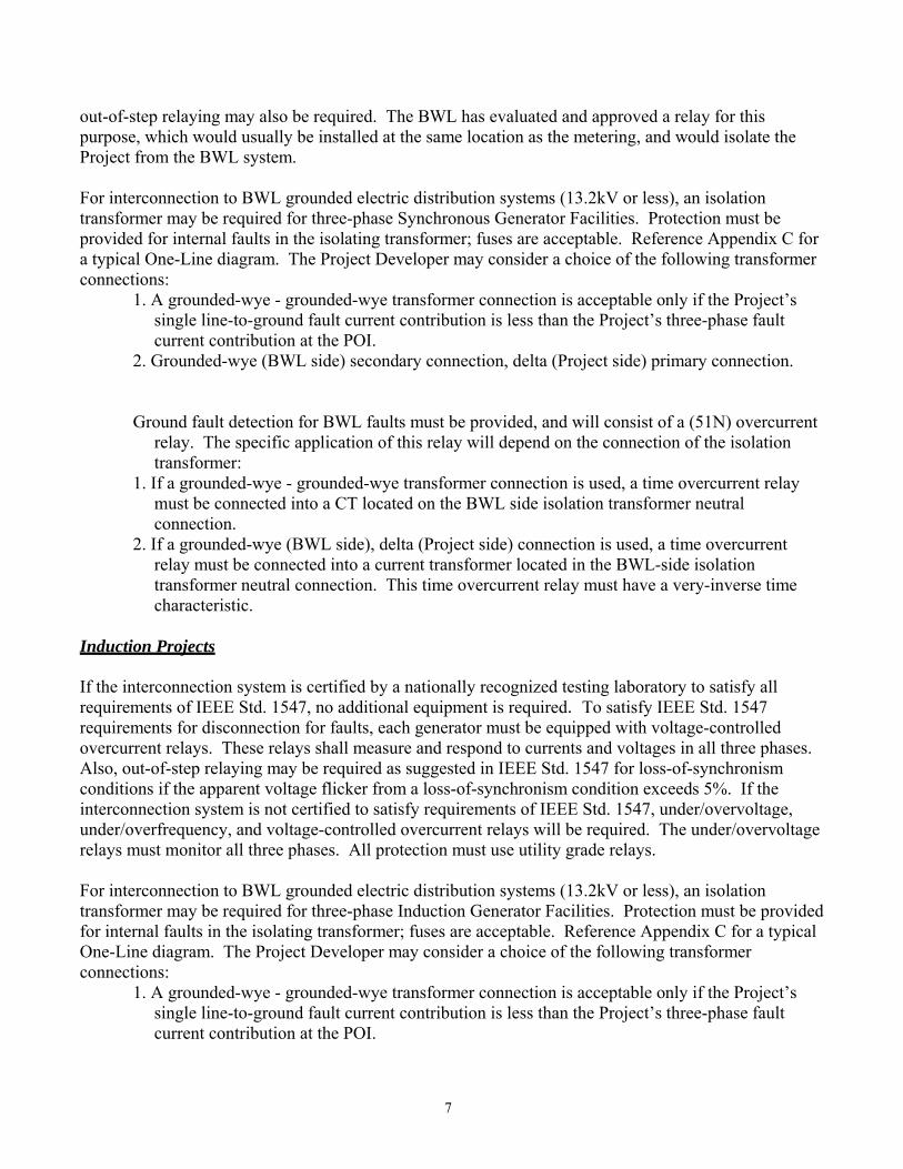
out-of-step relaying may also be required. The BWL has evaluated and approved a relay for this purpose, which would usually be installed at the same location as the metering, and would isolate the Project from the BWL system. For interconnection to BWL grounded electric distribution systems (13.2kV or less), an isolation transformer may be required for three-phase Synchronous Generator Facilities. Protection must be provided for internal faults in the isolating transformer; fuses are acceptable. Reference Appendix C for a typical One-Line diagram. The Project Developer may consider a choice of the following transformer connections:
1. A grounded-wye - grounded-wye transformer connection is acceptable only if the Project’s single line-to-ground fault current contribution is less than the Project’s three-phase fault current contribution at the POI.
2. Grounded-wye (BWL side) secondary connection, delta (Project side) primary connection.
Ground fault detection for BWL faults must be provided, and will consist of a (51N) overcurrent relay. The specific application of this relay will depend on the connection of the isolation transformer:
1. If a grounded-wye - grounded-wye transformer connection is used, a time overcurrent relay must be connected into a CT located on the BWL side isolation transformer neutral connection.
2. If a grounded-wye (BWL side), delta (Project side) connection is used, a time overcurrent relay must be connected into a current transformer located in the BWL-side isolation transformer neutral connection. This time overcurrent relay must have a very-inverse time characteristic.
Induction Projects If the interconnection system is certified by a nationally recognized testing laboratory to satisfy all requirements of IEEE Std. 1547, no additional equipment is required. To satisfy IEEE Std. 1547 requirements for disconnection for faults, each generator must be equipped with voltage-controlled overcurrent relays. These relays shall measure and respond to currents and voltages in all three phases. Also, out-of-step relaying may be required as suggested in IEEE Std. 1547 for loss-of-synchronism conditions if the apparent voltage flicker from a loss-of-synchronism condition exceeds 5%. If the interconnection system is not certified to satisfy requirements of IEEE Std. 1547, under/overvoltage, under/overfrequency, and voltage-controlled overcurrent relays will be required. The under/overvoltage relays must monitor all three phases. All protection must use utility grade relays. For interconnection to BWL grounded electric distribution systems (13.2kV or less), an isolation transformer may be required for three-phase Induction Generator Facilities. Protection must be provided for internal faults in the isolating transformer; fuses are acceptable. Reference Appendix C for a typical One-Line diagram. The Project Developer may consider a choice of the following transformer connections:
1. A grounded-wye - grounded-wye transformer connection is acceptable only if the Project’s single line-to-ground fault current contribution is less than the Project’s three-phase fault current contribution at the POI.

8
2. Grounded-wye (BWL side) secondary connection, delta (Project side) primary connection.
In cases where it can be shown that self excitation of the induction generator cannot occur when isolated from the BWL, the BWL may waive the requirement that the Project Developer provide protection for BWL system ground faults. Otherwise ground fault detection for BWL faults must be provided, and will consist of a (51N) overcurrent relay. The specific application of this relay will depend on the connection of the isolation transformer:
1. If a grounded-wye - grounded-wye transformer connection is used, a time overcurrent relay must be connected into a CT located on the BWL side isolation transformer neutral connection.
2. If a grounded-wye (BWL side), delta (Project side) connection is used, a time overcurrent relay must be connected into a current transformer located in the BWL-side isolation transformer neutral connection.
NOTE: This time overcurrent relay must have a very-inverse time characteristic.
Inverter-Type Projects If the interconnection system is certified by a nationally recognized testing laboratory to satisfy all requirements of IEEE Std. 1547, no additional equipment is required. If the interconnection system is not certified to satisfy requirements of IEEE Std. 1547, under/overvoltage, and under/overfrequency, will be required. The under/overvoltage relays must monitor all three phases. All protection must use Utility grade relays. If an isolation transformer is used for three-phase installations, the isolation transformer (without generation on-line) must be incapable of producing ground fault current to the BWL system such as a grounded-wye (BWL side) secondary connection, delta (Project side) primary connection. Protection must be provided for internal faults in the isolating transformer; fuses are acceptable. If the inverter has passed a certified anti-island test, the BWL may waive the requirement that the Project Developer provide protection for BWL system ground faults. Otherwise ground fault detection for BWL faults must be provided, and will consist of a (51N) overcurrent relay. The grounded-wye (BWL side), delta (Project side) connection requires a time overcurrent relay connected into a current transformer located in the BWL-side transformer neutral. This time overcurrent relay must have a very-inverse time characteristic. Reference Appendix C for a typical One-Line diagram for induction generation.
MISCELLANEOUS OPERATIONAL REQUIREMENTS
Standby Power Standby power will be provided under the terms of the BWL Rules and Regulations For Electric Service an approved rate set forth in the BWL Rate Schedule. The Project Developer should be aware that such standby power may require a separate meter be installed at the Project. If the Project is outside of the BWL’s franchise area, it will be the Project Developer’s responsibility to arrange contractually and technically for the supply of its facility’s standby, maintenance, and any supplemental power needs.

9
System Stability and Site Limitations The Stiffness Ratio is the combined three-phase short circuit capability of the Project and the BWL divided by the short circuit capability of the Project measured at the POI. A stability study may be required for Projects with a Stiffness Ratio of less than 40. Five times the generator rated kVA will be used as a proxy for short circuit current contribution for induction generators. For synchronous Projects, with a Stiffness Ratio of less than 40, the BWL requires special generator trip schemes or loss of synchronism (out-of-step) relay protection. If the apparent voltage flicker from a loss-of-synchronism condition exceeds 5%, an out-of-step relay will be required. This type of protection is typically applied at the POI and trips the entire Project off-line, if instability is detected, to protect the BWL electric system and its customers. If the project Developer chooses not to provide for mitigation of unacceptable voltage flicker (above five percent), the BWL may disallow the interconnection of the Project or require a new dedicated interconnection at the Project Developer’s expense. The Project Developer is responsible for evaluating the consequences of unstable generator operation or voltage transients on the Project equipment and determining, designing, and applying any relaying which may be necessary to protect that equipment. This type of protection is typically applied on individual generators to protect the generator facilities. The BWL will determine if operation of the Project will create objectionable voltage flicker and/or disturbances to other BWL customers and develop any required mitigation measures at the Project Developer’s expense.
REVENUE METERING Installation of BWL metering equipment and applicable rates, including sale of energy to the BWL shall be in accordance with the BWL Rules and Regulations For Electric Service and BWL Rate Schedule. The BWL will own, operate, and maintain all required billing metering equipment at the Project. The billing metering will meter both real and reactive interconnection flows between the Project and the BWL electric system. Where applicable, separate metering of station power may be required to accurately meter the generation facility load when the Project is off-line.
The Project Developer shall provide authorized employees and agents of the BWL access to the premises at all times to install, turn on, disconnect, inspect, test, read, repair, or remove the metering equipment. The Project Developer may, at its option, have a representative witness this work.
The Project Developer may be required to provide, at no cost to the BWL, a dedicated dial-up voice-grade circuit (POTS line) to allow remote access to the billing meter by the BWL. This circuit shall be terminated within ten feet of the meter involved.
The metering installations shall be constructed in accordance with the practices, which normally apply to the construction of metering installations for residential, commercial, or industrial customers. For Projects with multiple generators, metering of each generator may be required. When practical, multiple generators may be metered at a common point provided the metered quantity represents only the gross generator output. The BWL shall supply to the Project Developer all required metering equipment and the standard detailed specifications and requirements relating to the location, construction, and access of the metering installation and will provide consultation pertaining to the meter installation as required. The BWL will endeavor to coordinate the delivery of these materials with the Project Developer’s installation schedule.

10
The Project Developer may be required to provide a mounting surface for the metering equipment, a conduit for instrument transformer secondary wiring to meter cabinets, and a conduit for communication links as required. The mounting surface and location must meet the BWL’s specifications and requirements. The responsibility for installation of the equipment is shared between the BWL and the Project Developer. The Project Developer may be required to install some of the metering equipment on its side of the POI, including cabinets, conduits, and mounting surfaces. The BWL shall install the instrument transformers, the meters, and communication links. The BWL will endeavor to coordinate the installation of these items with the Project Developer's schedule during normal scheduled business hours. Non-Flow-back Projects A BWL meter will be installed that only records energy deliveries to the Project. Flow-back Projects Special billing metering will be required. If telemetering is required, the billing metering will be included as part of the telemetering installation. COMMUNICATIONS The BWL will determine the need for data and operational status and control communications and the type(s) of communication systems to be utilized. In the event such direct communications are required, the customer shall be responsible for the ordering, acquiring, installation, maintenance, and ongoing costs of the required analog phone line(s) including the monthly charges for the telephone lines and any rental equipment required by the local telephone provider. All telephone circuits (both voice and data) must be analog circuits. At the BWL’s discretion, the BWL may select an alternative communication method, such as wireless or fiber optic communications. Regardless of the method, the Project Developer will be responsible for all costs associated with the material and installation, whereas the BWL will be responsible to define the specific communication requirements. A dedicated dial-up voice-grade circuit (POTS line) is required for access to the billing meter by the BWL. When DTT is required, a modular RJ-11 jack must also be installed within six feet of the billing metering equipment, to allow the BWL to use this circuit for voice communication with personnel performing master station checkout of the RTU. This dial-up voice-grade circuit shall be a local telephone company provided business measured line without dial-in or dial-out call restrictions. If DTT is required, a separate dedicated 4-wire, Class A, Data Circuit must be installed and protected as specified by the local telephone provider for each DTT receiver and for the RTU. The circuit must be installed in rigid metallic conduit from the RTU and each DTT receiver to the point of connection to the telephone utility equipment. Wall space must be provided for adjacent mounting next to the telephone board, of the billing metering panel and a telemetry enclosure. The billing metering panel is typically 60 inches high by 48 inches wide and the telemetry enclosure is typically 24 inches high by 24 inches wide.
11
A clear space of 4.5 feet in front of this equipment is required to permit maintenance and testing. A review of each installation shall be made to determine the location and space requirements most agreeable to the BWL and the Project Developer. INTERCONNECT APPLICATION (Ref. Figure 1 the Interconnection Process) A BWL customer desiring to utilize cogeneration or small power production equipment interconnected to the BWL electric system shall first make application with the BWL Generator Interconnection Application form (Appendix A) with the additional appropriate form(s) (Appendix B & C) by size and type of generation contained herein. The application, required interconnection data, and an application fee are all together needed for a complete submittal. The BWL will acknowledge receipt of the application, data, application fee, and proceed to review the data for completeness and system impact. Small interconnect systems found in compliance with the BWL system parameters outlined above and not for parallel operation with the BWL will be verified by inspection and the customer authorized to operate the interconnected equipment by an authorized BWL representative on the Application form. In the event the BWL review determines further analytical studies to accommodate the impact and installation of the interconnect facilities is needed an Interconnection Study Agreement (Appendix D) must be executed. Upon completion of the study an Interconnection and Operation Agreement (Appendix E) will be prepared by the BWL based on the Interconnection Study. The Operation Agreement shall be duly executed before the BWL project is implemented to connect the customer’s facilities to the BWL electric system. PROJECT DESIGN AND CONSTRUCTION
After the Interconnection and Operating Agreement is executed, the BWL will proceed to acquire necessary rights-of-way, procure required equipment, and design and construct the BWL portion of the Interconnection Facilities. ONGOING OPERATIONS The Project Developer and BWL will exchange contact information and update this information from time to time.

12
Figure 1-Interconnection Process
BWL Receives Interconnection Application + Data + Filing Fee
BWL Acknowledges Receipt
Interconnection Application Complete? No
Yes
Unapproved Application Returned To Developer With Explanation
BWL Review of Application Data. Determine Need For System Study. No
Yes
Parallel Operation? Yes No
Execute Study Agreement
BWL Performs Interconnection Study
Approve Application
Execute Interconnection and Operating Agreement
Project Design & Construction
BWL Testing and Interconnection

13
R2: Third party Facility Interconnection Requirements
In the event of an Entity interested in connecting to BWL generation that is used to interconnect to the interconnected Transmission systems, will be required to adhere to the BWL published procedural guidelines.
The BWL, as a Generator Owner, shall within 45 days of having an executed Agreement to evaluate the reliability impact of interconnecting a third party Facility to the existing Generating Facility that is used to interconnect to the interconnected Transmission System, document and publish its Facility connection requirements. The BWL shall make available evidence that it has met all applicable requirements as stated in Requirement R2.
As the BWL is both a Generator Owner and Transmission Owner, the Transmission Owner would be aware of any generation added at BWL generation facilities and would adhere to the interconnection procedures accordingly.
R3: SYSTEM PEFORMANCE PLANS 3.1 Coordination with ITC The BWL keeps ITC informed of all facility interconnection projects such as a high voltage substation or a generating station by email or written letter. For an ITC transmission line to BWL End-User project such as College Substation, BWL expresses interest in the interconnection to ITC. After the Facility Interconnection Study Agreement is done and fees are paid, a kick-off /scoping meeting is held to develop a scope document for a System Impact Study to be done by ITC. After the study is finished, a joint meeting is held to evaluate the reliability impact of the new facilities and their connection on the interconnected systems and make jointly coordinated recommendations. For a new generation project such as the Reo Town Facility, the BWL performs a Transmission Planning Study to evaluate the reliability impact of this new facility on the existing transmission system and share its findings with ITC to check if it agrees with similar study by ITC through email communications. Once the impact of the new project is known to both BWL and ITC, meetings are held for joint evaluation and recommendations.
3.1.1 Procedures for coordinated joint studies of new facilities and their impacts on the interconnected transmissions systems. The procedures for coordinated joint studies of new facilities and their impacts on the interconnected transmissions systems as follows: 1. The Facility Interconnection Study is started with a kick-off/scoping meeting to develop a scope of
study. 2. The Planning Engineers gather system data required for the new Facility Interconnection and
perform the study using BWL System Planning Criteria as stipulated in Electric System Design & Operation Criteria, Rev.1. and all other applicable NERC Reliability Standards and applicable Regional, Sub-regional, Power Pool, and individual system planning criteria and facility connection requirements.

14
3. The project assessment will include steady-state, short-circuit, and dynamic studies as necessary to
evaluate system performance in accordance with Reliability Standard TPL-001-0. The study should also consider alternatives for cost effective solution.
4. The purpose of this study is to provide an initial assessment of the projects impact. The results of
the study will indicate whether the transmission system is capable of accommodating the new facility with minimal or no system upgrade.
5. The cost associated with any equipment modifications shall be the responsibility of the requesting party. The requesting party shall also be responsible for obtaining any required Right-of-Way (ROW) or easements from landowners, as well as any required permits needed for the interconnection. 6. If no upgrade is needed, then project cost and time required are estimated. In case system upgrade is
needed, then the project is sent for detailed System Planning and Analysis work.

15
7. Joint meetings are held at different phases of development to evaluate the results of system impact study, cost estimates, time schedule and design details and jointly coordinated recommendations are made.
3.1.2 Procedures for notification of new or modified facilities to others (those responsible for the reliability of the interconnected transmission system) as soon as feasible. Any entity seeking to interconnect, generation, transmission, or end-user facilities shall contact the following individual as soon as feasible: Utility Services Board of Water & Light PO Box 13007 Lansing, Michigan 48901-3007 Phone: (517) 702-6700 The requesting entity shall provide all required technical information needed to evaluate impact of the proposed facilities on the generation, transmission, and/or end-user facilities. The BWL will make notification of new or modified facilities as soon as feasible by email and letters to ITC, MISO and RFC who are responsible for the reliability of the interconnected transmission system.
3.1.3 Voltage level and MW and MVAR capacity or demand at point of connection. The Project Developer needs to assure sufficient voltage regulation at its facility to assure satisfactory generator operation over the range of voltage variation expected on the BWL electric system. Any isolating transformer to be installed must comply with the current ANSI Standard C57.12. The transformer must have voltage taps on the high and/or low voltage windings. The proper selection and specification of transformer impedance is important relative to enabling the proposed Project to meet the BWL’s reactive power requirements. The isolation transformer configuration will be considered by the BWL during the Application Data review following submittal of the Application. The significant cost and procurement time of some transformers should encourage the Project Developer to consult with the BWL prior to submitting an application or procuring the transformer(s). The voltage level of a new facility interconnection will be determined by the point of interconnection with the BWL system. The customer load requirements of the new facilities will be determined based on joint studies. For transmission interconnection, the nominal voltage is 138kV. The maximum normal voltage is 148 kV (1.05 PU) and the minimum normal voltage is 135.2kV (.98 PU). The minimum emergency voltage is 131.1 kV (0.95 PU). For planning purposes, the 13.2kV, 8.32 kV and 4.16 kV distribution systems shall be designed such that the following performance criteria are met: Primary circuit voltage shall not be below 12.87 kV on the 13.2 kV system, 8.112 kV on the 8.32 kV system and 4.056 kV on the 4.16 kV system.

16
3.1.4 Breaker Duty and Surge Protection. An isolation device would be placed at the Point of Interconnection (POI). It can be a circuit breaker, circuit switcher, pole top switch, load-break disconnect, etc., depending on the electrical system configuration. The following are required of the isolation device: Must be approved for use on the BWL system. Must comply with current relevant ANSI and/or IEEE Standards. Must have load break capability, unless used in series with a three-phase interrupting device. Must be rated for the application. If used as part of a protective relaying scheme, it must have adequate interrupting capability. The
BWL will provide maximum short circuit currents and X/R ratios available at the POI upon request. Must be operable and accessible by the BWL at all times (24 hours a day, 7 days a week) The BWL will determine if the isolation device will be used as a protective tagging point. If the determination is so made, the device must have a visible open break, provisions for padlocking in the open position and it must be gang operated. If the device has automatic operation, the controls must be located remote from the device. Surge protection shall be provided by surge arresters that will be selected to coordinate with the BIL rating of major equipment components. All the equipment must be grounded properly to ensure that protection system operates properly as designed. 3.1.5 System Protection and Coordination The BWL system protection requirements are intended to protect BWL’s transmission and generation systems from equipment damage, to ensure the safety of the general public, BWL and other utility personnel, to minimize any adverse operating conditions affecting BWL and its customers and to comply with any NERC or BWL operating criteria. Natural hazards (lightning, ice, and wind), human interference (vehicles, vandalism) and electrical equipment malfunction can cause damage to the electric transmission and distribution system. Such causes can result in short circuits or faults, as commonly referenced in the utility industry. Faults create a safety hazard for personnel, jeopardize the stability of the entire electrical network, and can impose severe damage to equipment. the electrical equipment that comprises a utility network is protected by the various protection systems. Generation or other new electric energy sources connected in parallel with the electric transmission and distribution system have the potential to create two problems for the utility, as follows: 1. Provides an additional energy source(s) that increase fault current magnitudes. This additional fault current can interfere with the operation of existing protective devices on the system. 2. The generation or other electric energy source, along with a portion of the BWL electric system, can become isolated from the bulk of the electric system. Such isolation is commonly referred to as islanding and is considered most unsafe and thus is not an acceptable mode of operation. The majority of faults on an overhead electric system are transient in nature. By quickly de-energizing the line and then automatically re-energizing or reclosing it, the overhead fault is usually cleared and the system returned to service. The BWL follows the common utility practice of reclosing the circuit
17
breaker of the overhead 13.2 kV circuits originating at 138 kV transmission substations. Remote reclosing methods may be used elsewhere in the circuit. Generating equipment connected to electric systems utilizing reclosing protection schemes can experience severe damage during automatic reclosing. The damage is often the result of the reconnection of the electric system and generator being out of synchronism. Such an event may result in a hazard and/or damage to both the BWL and the customer systems. Studies must then be performed to evaluate any adverse effects to the electric system, solutions to prevent such effects, and required modification of the BWL electric system including system protection. The extent of any modifications is dependent upon both the size of the generation or other electric source and the electrical characteristic of the BWL electric system at and near the point of common coupling. Thus, the BWL will require, in most cases, the customer-owned generation to have BWL specified protection systems at the point of interconnection dedicated to protect the BWL electrical system. The customer is also responsible for protecting customer-owned equipment directly impactedby the aforementioned natural, human, equipment malfunction hazards, along with BWL protection device and reclosing operations. The relay settings as detailed in this section will generally conform to the values specified in IEEE Std. 1547 as applied in the vast majority of applications. The Customer shall design the protection and control system and issue protective device settings for each individual project that will address the settings for these protective functions. The customer shall coordinate with the BWL in the design of the protection and control system and in the creation of the protective device settings to ensure adherence to BWL protection standards. The BWL shall review and approve the final protection and control system design and settings. Undervoltage Relays If an interconnection system which is certified to meet IEEE Std. 1547 is used, the undervoltage setpoints as defined in IEEE Std. 1547 will be used initially. Otherwise, the undervoltage relays will initially be set to trip at 88% of the nominal primary voltage at the relay location, and must reset from a trip condition if the voltage increases to 90% of the nominal primary voltage at the relay location. To accommodate variations in this criteria, the trip point of the relays shall be adjustable over a range of 70% of the nominal voltage to 90% of the nominal voltage. The trip time shall not exceed 1.0 seconds at 90% of the relay setting. Overvoltage Relays If an interconnection system which is certified to meet IEEE Std. 1547 is used, the overvoltage setpoints as defined in IEEE Std. 1547 will be used initially. Two steps of overvoltage relaying are required. For the first overvoltage set point, the overvoltage relays will initially be set to trip at 107% of the nominal primary voltage at the relay location, and must reset from a trip condition if the voltage decreases to 105% of the nominal primary voltage, at the relay location. To accommodate variations in this criteria, the trip point of the relays shall be adjustable over a range of 105% of the nominal voltage to 120% of the nominal voltage. The trip time shall not exceed 1.0 seconds at 110% of the relay setting. For the second overvoltage set point, the overvoltage relays will initially be set to trip at 120% of the nominal primary voltage at the relay location, and must reset from a trip condition if the voltage decreases

18
to 118% of the nominal primary voltage at the relay location. To accommodate variations in this criteria, the trip point of the relays shall be adjustable over a range of 115% of the nominal voltage to 140% of the nominal voltage. The trip time shall be instantaneous (relay operating time not to exceed 0.02 seconds at 110% of the trip setting). Underfrequency Relays If an interconnection system which is certified to meet IEEE Std. 1547 is used, the underfrequency setpoints as defined in IEEE Std. 1547 will be used initially. Otherwise, the underfrequency relay will initially be set for a trip point of 58.5 Hz, and must trip within 0.2 seconds. Relays with an inverse time characteristic (where the trip time changes with respect to the applied frequency) are not acceptable. These relays must respond reliably for applied source voltages as low as 70% of the nominal voltage.
51V Relays – Voltage Controlled Overcurrent Relays For synchronous generator applications, the (51V) relays must be set to detect any phase faults that may occur between the generator and the nearest three-phase fault clearing device on the BWL system. Since these faults may take up to 1-second to detect and isolate, the appropriate saturated direct-axis reactance of the generator will be used depending on its time constants. The settings of this device will consider the relay manufacturer’s recommended practice for the type of generator and prime mover (mechanical energy source), and will be determined by the BWL for the specific system application.
59N Relay – Ground Fault Detection This relay will be applied to detect ground faults on the BWL system when the Project is connected to a grounded BWL system via an ungrounded transformer winding. This relay will initially be set for a 10% shift in the apparent power system neutral. For an ungrounded-wye transformer winding with a single 120 V secondary VT, the setting will initially be 12 Volts. For a delta transformer winding with broken delta 120 V secondary VTs, the setting will initially be 20 Volts. The time delay will initially be 1 second. 51N Relay – Ground Fault Detection This relay will be applied to detect ground faults on the BWL system when the Project is connected to a grounded BWL system via a grounded-wye transformer winding, and will be connected into a CT in the transformer neutral connection. This relay will be set to detect faults on the directly connected BWL system, and the timing will be set to comply with BWL practice for overcurrent relay coordination. The CT ratio and specific relay setting will be determined via a fault study performed by the BWL. 32 Relay – Reverse Power The reverse power relay must be selected such that it can detect a power flow into the BWL system of a small fraction of the overall generator capacity. The relay will normally be set near its minimum (most sensitive) setting, and will trip after a 1 second time delay. The delay will avoid unnecessary tripping for momentary conditions.

19
3.1.6 Metering and Telecommunications Installation of BWL metering equipment and applicable rates, including sale of energy to the BWL shall be in accordance with the BWL Rules and Regulations For Electric Service and BWL Rate Schedule.
The BWL will own, operate, and maintain all required billing metering equipment at the Project. The billing metering will meter both real and reactive interconnection flows between the Project and the BWL electric system. Where applicable, separate metering of station power may be required to accurately meter the generation facility load when the Project is off-line. The Project Developer shall provide authorized employees and agents of the BWL access to the premises at all times to install, turn on, disconnect, inspect, test, read, repair, or remove the metering equipment. The Project Developer may, at its option, have a representative witness this work. The Project Developer may be required to provide, at no cost to the BWL, a dedicated dial-up voice- grade circuit (POTS line) to allow remote access to the billing meter by the BWL. This circuit shall be terminated within ten feet of the meter involved. The metering installations shall be constructed in accordance with the practices, which normally apply to the construction of metering installations for residential, commercial, or industrial customers. For Projects with multiple generators, metering of each generator may be required. When practical, multiple generators may be metered at a common point provided the metered quantity represents only the gross generator output. The BWL shall supply to the Project Developer all required metering equipment and the standard detailed specifications and requirements relating to the location, construction, and access of the metering installation and will provide consultation pertaining to the meter installation as required. The BWL will endeavor to coordinate the delivery of these materials with the Project Developer’s installation schedule. The Project Developer may be required to provide a mounting surface for the metering equipment, a conduit for instrument transformer secondary wiring to meter cabinets, and a conduit for communication links as required. The mounting surface and location must meet the BWL’s specifications and requirements. The responsibility for installation of the equipment is shared between the BWL and the Project Developer. The Project Developer may be required to install some of the metering equipment on its side of the POI, including cabinets, conduits, and mounting surfaces. The BWL shall install the instrument transformers, the meters, and communication links. The BWL will endeavor to coordinate the installation of these items with the Project Developer's schedule during normal scheduled business hours. If DTT is required, telemetry to monitor the DTT is also required. Disturbance monitoring is also recommended as being beneficial to the Project Developer and the BWL, but is not required in all cases. Telemetry and disturbance monitoring is generally required for larger capacity Projects that will operate in the Flow-back Mode. For Projects that will operate in the Non-Flow-back Mode, the requirement for telemetry will be determined on a case-by-case basis as part of the Interconnection Study. Telemetry enables the BWL to operate the electric system safely and reliably under both normal and emergency conditions. The Utility measures its internal load plus losses (generation) on a real-time basis via an extensive telemetry system. This system sums all energy flowing into the BWL electric

20
system from Projects interconnected to the system and from interconnections with other utilities. During system disturbances when portions of the electrical systems are out of service, it is essential to
know if a Project is on line or off line to determine the proper action to correct the problem. Time savedduring restoration activities translates to fewer outages and outages of shorter duration for the BWL’s customers. The BWL evaluates the performance of the overall protective system for all faults on the electric system. It is critical that sufficient monitoring of the protective system is in place to determine its response. It is preferable to deploy disturbance monitoring into all Projects, but it can be expensive to deploy. Therefore, disturbance monitoring is required only for installations that already require telemetry. The Project Developer shall provide a suitable indoor location, approved by the BWL, for the BWL’s owned, operated, and maintained Remote Terminal Unit (RTU). The location must be equipped with a 125 V DC power supply. The Project Developer must provide the necessary phone and data circuits, and install a telephone backboard for connections to the BWL RTU and metering equipment. All phone circuits must be properly protected as detailed in IEEE Std. 487. When telemetry is required, the following values will be telemetered:
1. Real and reactive power flow at the POI. 2. Voltage at the POI. 3. The status (normal/fail) of protective relay Communication Channels. A status indication of
"FAIL" indicates the Communication Channel used for relaying (i.e. transfer trip) is unable to perform its protective function. This includes the following individual contact from each individual Direct Transfer Trip receiver, required by the BWL:
i. Loss-of-guard (LOG) alarm ii. Receive-trip relay (RTX). iii. Lockout relay.
4. The status (open/closed) of the main isolating breaker and each generating unit breaker (if the Project is composed of multiple units, a single logical (OR) status of the individual Project breaker states, indicating all Project breakers are open or any one or more Project breakers are closed, is permissible). A closed status would be indicated if any individual generator is on line.
The RTU will be equipped with “sequence of events” recording. The Project Developer shall provide, wired to a terminal block near the RTU panel, the following general equipment Auxiliary Contacts and relay contacts:
1. An output contact of an instantaneous relay to act as a ground fault detector for faults on the BWL electric system. This relay shall be connected into the same sensing source as the ground fault protective relay required by the BWL.
2. Each and every trip of an interconnection isolation device, which is initiated by any of the generator interconnection relaying schemes required by the BWL.
3. Each and every trip of an interconnection isolation device, which is initiated by any of the protective systems for the generator.
4. Each and every trip or opening of an interconnecting isolation device, which is initiated by any other manual or electrical means.
5. A contact indicating the position of the Project’s primary-side main breaker. 6. A contact indicating operation of the over/undervoltage relays.
7. A contact indicating operation of the under/over freq. relay or the BWL’s gnd fault relay.8. A contact indicating operation of the Project provided transformer bank relaying.

21
9. A contact indicating operation of any of the (51V) relaying. 10. A contact indicating the position of the high-side fault-clearing device. 11. A contact indicating the position of the reverse power relay, if said, relay is required by the BWL.
If any of the functions indicated in items 2-4, 6, 7, 9, or 11 are combined into a multi-functional device, either:
1. Each of those functions must be monitored independently on the RTU, or 2. Provisions acceptable to the BWL must be provided to interrogate the multi-functional device
such that the operation of the individual functions may be evaluated separately. Telemetry, when required, will be provided by the BWL at the Project Developer's expense. In addition to other telemetry costs, a one-time charge may be assessed to the Project Developer for equipment and software installed at the BWL’s Electric System Operations Center to process the data signals.
3.1.7 Grounding and Safety Issues Refer to IEEE-1547 Section 4 Interconnection technical specifications and requirements. 3.1.8 Insulation and Insulation Coordination Insulation and insulation coordination shall be specified in a manner to insure the integrity of the electrical power system and the safety of BWL customers and personnel. It is the responsibility of the connecting entity to perform a study on proper insulation practices and submit to the designated BWL engineer. Surge arresters shall be selected to coordinate with the BIL rating of major equipment components and shall comply with recommendations set forth in the current ANSI Standard C62.2. 3.1.9 Voltage, Reactive Power, and Power Factor Control Synchronous generators that will operate in the Flow-back Mode must be dynamically capable of providing 0.90 power factor lagging (delivering reactive power to the BWL) and 0.95 power factor leading (absorbing reactive power from the BWL) at the POI. The POI is the location where the BWL accepts delivery of the output of the Project. The POI can be the physical location of the billing meters or a location where the billing meters are not located, but adjusted for line and transformation losses. Induction and Inverter-Type Projects that will operate in the Flow-back Mode must provide for their own reactive needs (steady state unity power factor at the POI). To obtain unity power factor, the Induction or Inverter-Type Project can:
1. Install a switchable Volt-Ampere reactive (VAR) supply source to maintain unity power factor at the POI; or
2. Provide the BWL with funds to install a VAR supply source equivalent to that required for the Project to attain unity power factor at the POI at full output.
There are no interconnection reactive power capability requirements for Synchronous, Induction, and Inverter-Type Projects that will operate in the Non-Flow-back Mode. The BWL Rate Schedule contain power factor adjustments based on the power factor of the metered load at these facilities.

22
3.1.10 Power Quality Impacts Newly interconnected facilities shall not cause excessive voltage flicker or harmonic distortion on the electric facilities of the BWL. IEEE Standard 519 provides definitions and limits on acceptable levels of voltage fluctuation and harmonic distortion. New facilities connecting to the BWL’s system shall comply with the limits set by IEEE 519. Newly connected facility switched loads and capacitor banks shall not result in a voltage step change greater than 3% on the BWL system, regardless of the frequency of occurrence. Voltage unbalance shall not exceed 1.0% measured at the point-of interconnection. The allowable limit applies to normal steady-state operating conditions and is measured by the formula: Voltage Unbalance (%) = (Max. Deviation from Avg. Voltage ÷ Avg. Voltage) x 100 Average voltage is defined as the sum of the three phase voltages divided by three. 3.1.11 Equipment Ratings The BWL will determine the individual equipment ratings for specific Transmission Owner’s interconnection facilities and network upgrades if needed during the detailed design of the facilities. The Customer shall size the interconnection facilities using applicable reliability standards, good utility practice and the information provided in the interconnection evaluation study to ensure that the customer’s interconnection facilities appropriately coordinate with the BWL’s system. The BWL will determine the required short circuit ratings for all Transmission Owner’s interconnection facilities and network upgrades during the detailed design of such items. The interconnection customer agrees to provide appropriately sized or short circuit rated Customer’s interconnection facilities comparable to those required by Transmission Owner using applicable reliability standards, good utility practice, and the information provided in the interconnection evaluation study. The Interconnection Customer shall provide the GSU transformer impedance data and its line conductor impedance data to the POI including the positive, negative, and zero sequence values to be used in calculating fault impedance values. Equipment must meet minimum ratings required to operate the facility at full load under normal ratings of the equipment. This includes, but is not limited to, voltage class, ampacity, available fault current rating, fault closing rating, and basic impulse level (BIL). All current carrying devices and equipment shall be designed to carry the maximum loads that are predicted and used in load flow analysis. The BWL shall have the right to review customer design and specifications to verify that equipment ratings are consistent with BWL criteria. Power Transformers Power transformers shall be designed, built, and tested in accordance with the latest version of ANSI 57 series, IEEE, NEMA, or any other applicable approved industry standard.

23
Circuit Breakers Circuit Breakers shall be designed, manufactured and tested in accordance with the latest revision of ANSI C37.12 or any other applicable approved industry standard. High Voltage Switches High voltage switches shall be designed, manufactured, and tested in accordance with the latest revision of ANSI C37.35-1976. Instrument Transformers Instrument Transformers shall be designed, manufactured and applied in accordance with IEEE Std. C57.13. Accuracy The burdens placed on instrument transformers shall be within the limits required to ensure the accuracy required by the application. Surge Arrestors The high voltage terminal of the surge arrestor is to be connected to the terminal of the protected equipment by the shortest and most direct path possible. The ground terminal of the surge arrestor is to be connected to the grounded portion of the protected equipment by the shortest and most direct path. The grounded portion of the protected equipment is to be connected directly to the grounding electrode. DC System The D.C. system shall be comprised of an appropriately sized station battery (125 Volts D.C. nominal), a battery charger, electrical disconnect devices, and a D.C. distribution panel. Standards Batteries shall be sized, installed, and maintained in accordance with the latest version of IEEE Std 485, ANSI/IEEE Std 450, and ANSI/IEEE Std 484. Reliability Batteries shall be maintained in the fully charged state by being continuously connected to a suitably sized charger that derives its energy from a highly reliable AC source. Distribution Panel A DC distribution panel shall be included that provides coordinated overcurrent protection from the battery to each individual DC load. The protective devices shall be rated for D.C. use. There shall be no cross connections between DC circuits. 3.1.12 Synchronizing of Facilities The Project Developer will be solely responsible for the required synchronizing equipment and for properly synchronizing the Project with the BWL’s electric system. Voltage fluctuation at the POI during synchronization shall be in accordance with IEEE Std. 1547 and limited to ±5%. The Project Developer will notify the BWL prior to synchronizing to and prior to scheduled disconnection from the BWL electric system. These requirements are directly concerned with the actual operation of the Project with the BWL:

24
The Project may not commence parallel operation until approval has been given by the BWL. The completed installation is subject to inspection by the BWL prior to approval. Preceding this inspection, all contractual agreements must be executed by the Project Developer.
The Project must be designed to prevent the Project from energizing into a de-energized BWL line. The Project’s circuit breaker or contactor must be blocked from closing in on a de- energized circuit.
The Project shall discontinue parallel operation with a particular service and perform necessary switching when requested by the BWL for any of the following reasons: 1. When public safety is being jeopardized. 2. During voltage or loading problems, system emergencies, or when abnormal sectionalizing
or circuit configuration occurs on the BWL system. 3. During scheduled shutdowns of BWL equipment that are necessary to facilitate
maintenance or repairs. Such scheduled shutdowns shall be coordinated with the Project. 4. In the event there is demonstrated electrical interference (i.e. Voltage Flicker, Harmonic
Distortion, etc.) to the BWL’s customers, suspected to be caused by the Project, and such interference exceeds then current system standards, the BWL reserves the right, at the BWL’s initial expense, to install special test equipment as may be required to perform a disturbance analysis and monitor the operation and control of the Project to evaluate the quality of power produced by the Project. In the event the Project is the source of the interference then the appropriate rule in BWL Rules and Regulations For Electric Service apply and will be implemented accordingly.
5. When either the Project or its associated synchronizing and protective equipment is demonstrated by the BWL to be improperly maintained, so as to present a hazard to the BWL system or its customers.
6. Whenever the Project is operating isolated with other BWL customers, for whatever reason. 7. Whenever a loss of communication channel alarm is received from a location where a
communication channel has been installed for the protection of the BWL system. 8. Whenever the BWL notifies the Project Developer in writing of a claimed non-safety
related violation of the Interconnection Agreement and the Project Developer fails to remedy the claimed violation within ten working days of notification, unless within that time either the Project Developer files a complaint seeking resolution of the dispute or the Project Developer and BWL agree in writing to a different procedure. 9. If the Project has shown an unsatisfactory response to requests to separate the generation from the BWL system, the BWL reserves the right to disconnect the Project from parallel operation with the BWL electric system until all operational issues are satisfactorily resolved.
3.1.13 Maintenance Coordination
A. All BOARD required interconnection devices must remain in service with relay settings as recorded on the "Board Relay Setting and Test Report Form". Proposed changes in relay settings must be submitted in writing to the BOARD for approval. Any modification of the existing interconnection or protection scheme requires prior written approval of the BOARD'S, Manager of Electric Planning Department, or his/her designee.
25
B. BOARD required interconnection equipment owned by APPLICANT shall be periodically tested by BOARD personnel at the APPLICANT'S expense. The APPLICANT shall schedule and provide the BOARD access for testing at reasonable hours. Copies of equipment test reports shall be forwarded to the BOARD'S Superintendent of System Operation or his/her designee and approved before APPLICANT may resume parallel operation. APPLICANT shall comply with the following requirements for BOARD required interconnection equipment:
1. Interconnection relays shall be tested at intervals not to exceed three years.
2. Individual relays shall be secondary bench tested by applying the appropriate currents,
voltages or frequencies. The relays must be tested at their specified setting to verify the minimum operating point at which relay will actuate (Minimum Pickup).
3. Lamicoid name plates shall be installed by APPLICANT adjacent to all BOARD-
required interconnection relays. Each relay name plate shall include the device number and the relay's function.
4. Non-revenue meter calibration shall be checked and all current transformers and potential
transformers shall be tested at intervals not to exceed six years. Current transformers shall be primary or secondary ratio tested. If the current transformers are secondary ratio tested, a voltage ratio must be performed to verify turns ratio.
C. Generation, transmission, or end-user customers need to take a maintenance outage that impacts
the LBWL facilities; they must follow the BWL Planned Outage Procedure
3.1.14 Operational Issues (abnormal frequencies and voltages) Refer to IEEE-1547 Section 5: Interconnection test specifications and requirements
3.1.15 Inspection Requirements for Existing or New Facilities The Project Developer must provide the BWL with 5-10 business days advance written notice, depending on the size of the project, of when the Project will be ready for inspection, testing, and approval. The Utility may review the design drawings, for approval, after the Interconnection Study has been completed. If reviewed, the BWL shall either approve the Project Developer's design drawings as submitted or return them to the Project Developer with a clear statement as to why they were not approved. Where appropriate, the BWL will indicate required changes on the engineering drawings. In the event that revisions are necessary to the Project Developer's submitted design drawings and the Project Developer submits revised design drawings to the BWL, then the BWL shall either approve, in writing, the Project Developer's revised design drawings as resubmitted, or return them to the Project Developer with a clear statement as to why they were not approved. Where appropriate, the BWL will indicate required changes on the engineering drawings. The BWL will retain one copy of the approved design drawings. In the event that the BWL exercises its option to Acceptance Test the proposed interconnection relays that protect the BWL electric system, then the BWL shall communicate the

26
results of that testing to the Project Developer for both the relays and the necessary documentation on the relays. In the event the Project Developer proposes a revision to the BWL’s approved relaying and control equipment used to protect the BWL electric system and submits a description and engineering design drawings of the proposed changes, the BWL shall either approve the Project Developer's amended design drawings or return them to the Project Developer with a clear statement as to why they were not approved. Where appropriate, the BWL will indicate required changes on the engineering drawings. Prior to final approval for Parallel Operation, the BWL’s specified relay calibration settings shall be applied and a commissioning test must be performed on the Project relaying and control equipment that involves the protection of the BWL electric system. The commissioning test must be witnessed by the BWL. Upon satisfactory completion of this test and final inspection, the BWL will provide written permission for Parallel Operation. If the results are unsatisfactory, the BWL will provide written communication of these results and required action to the Project Developer. 3.1.16 Communications and Procedures During Normal and Emergency Operating Conditions.
A. All oral operating communications between the parties shall be conducted through the BOARD'S Brush Electrical System Operating Center (B.E.S.O.C.). APPLICANT agrees to maintain direct phone service from the local phone company so that operating instructions from the BOARD can be given to the APPLICANT or its designated operator.
B. APPLICANT shall maintain daily operating communications with the BOARD'S Brush
Electrical System Operating Center. The operating communications shall include, but not be limited to, system paralleling or separation, scheduled and unscheduled shutdowns, equipment clearance, levels of operating voltage and power factors.
C. APPLICANT shall keep a daily operations log for its generating facility which shall include
information on generator output, unit availability, maintenance outages, circuit breaker trip operations and any significant events related to operation of the generating facility. APPLICANT shall send a copy of this log to the Manager of the BOARD'S Electric Planning Department, or his/her designee every 6 months and shall make the log available for review upon demand.
D. APPLICANT agrees to supply and timely update the BOARD'S Brush Electrical System
Operating Center of the following:
The current names and phone numbers of the personnel responsible for operating and maintaining the generating facility and any changes made to this list.
Any emergency situations which may adversely affect the BOARD’S electric system
integrity, or any requirement that BOARD de-energize a portion of the APPLICANT'S system under its control.

27
Any change in the mechanical or electrical condition that may affect capacity or the reliability of the APPLICANT'S generating facility.
Immediately upon discovery, any BOARD required interconnection relay that is either
inoperable or operating improperly.
Immediately upon discovery, any circuit breaker that has operated by a BOARD required interconnection relay, along with the relay targets that caused the circuit breaker to operate
Plans to manually parallel with or separate from the BOARD system and the times of
actual manual parallels and separations. Emergency separations shall be reported as soon as conditions permit.
R4. Facility Connection Requirement Documentation The Board of Water & Light shall maintain and update its Facility Connection Requirements document as necessary. The BWL’s FAC standards subject matter expert, with input from other Transmission Resources and Engineering department staff, shall be responsible for maintaining and updating these Facility Connection Requirements and making its Facility Connection Requirements available to requesting entities within 5 business days. The BWL has also made its Facility Connection Requirement available to the users of the transmission system, Regional Reliability Organization and NERC by publishing its Facility Connection Requirement document to the BWL website as follows: http://www.lbwl.com/uploadedFiles/MainSite/Content/About_the_BWL/Facilities/FacilityInterconnection.pdf
28
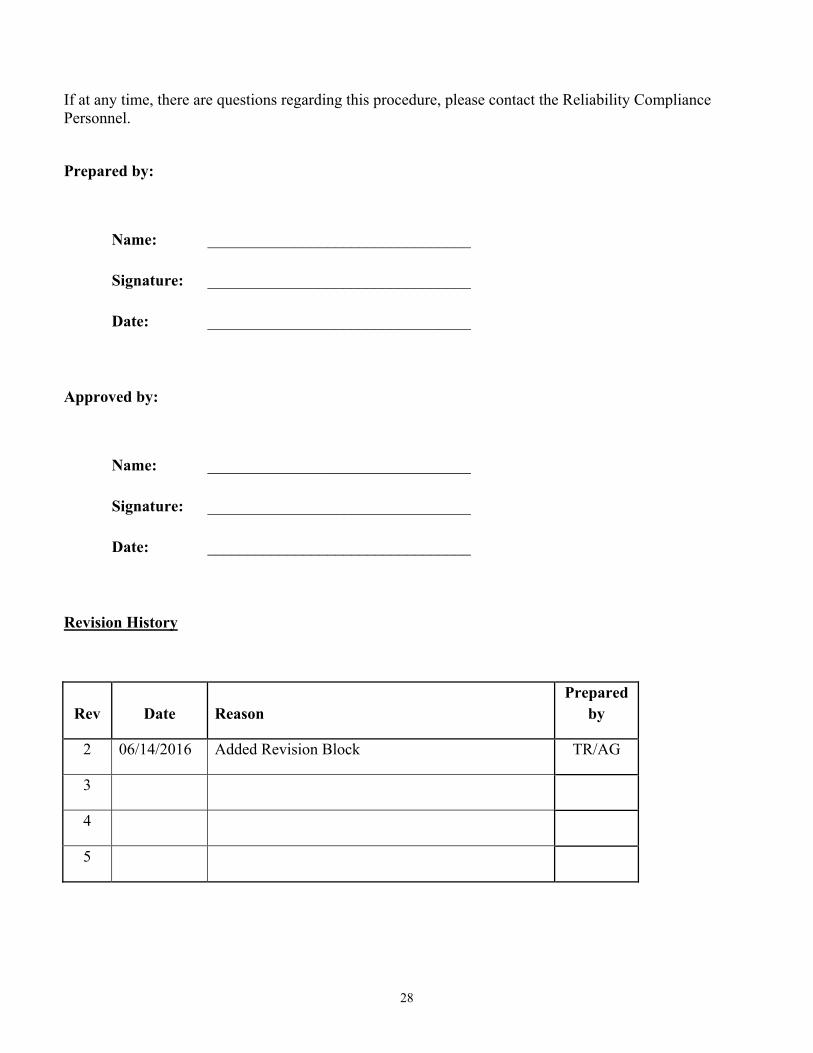
If at any time, there are questions regarding this procedure, please contact the Reliability Compliance Personnel.
Prepared by:
Name: _________________________________
Signature: _________________________________
Date: _________________________________
Approved by:
Name: _________________________________
Signature: _________________________________
Date: _________________________________
Revision History
Rev Date Reason Prepared
by
2 06/14/2016 Added Revision Block TR/AG
3
4
5

A-1
APPENDIX A
INTERCONNECTION APPLICATION

A-2
A-2 GENERATOR INTERCONNECTION APPLICATION
1. The undersigned, , Project Developer submits this Generator Interconnection Application and appropriate filing fee to interconnect
, a new Project, to the Board of Water & Light (BWL) Electric System or to increase the capacity of interconnected to the BWL Electric System.
, an existing Project
2. The undersigned requesting interconnection or an increase in the capacity of an existing
interconnection project to the BWL Electric System must provide the following information: Completed Interconnection Application Data sheet appropriate for the capacity rating and
type of generating unit(s), as found in the BWL’s Generator Interconnection Requirements (the appropriate Interconnection Application Data sheet must be attached to this Interconnection Application).
Description of the equipment configuration and proposed interconnection one-line diagram (one-line diagram must be attached to this Interconnection Application).
Project Developer (Single Point of Contact):
Name:
Address:
Phone Number:
Fax Number:
E-mail Address:
Project Site Address:
3. This Generator Interconnection Application shall be directed to the BWL representative as indicated below:
Utility Services Board of Water & Light PO Box 13007 Lansing, Michigan 48901-3007
Phone: 517-702-6700
4. I, the undersigned and authorized representative of , the Project, submit this Generator Interconnection Application and required technical data for the BWL. I understand that upon acceptance, the BWL shall subsequently provide an Interconnection Study Agreement, if said Interconnection Study is determined to be necessary. The Interconnection Study Agreement will include the Scope of the Interconnection Study. I also understand that I shall be required to furnish certain required technical data as requested by the Utility in support of this study and reimburse the Utility for its study expenses.

A-3
Authorized Signature:
Printed Name:
Title:
Company Name:
Date:
5. Upon review of the application data, the BWL hereby recommends:
Subject to verification by visual inspection, interconnection for non-parallel operation is authorized.
Subject to verification by visual inspection, interconnection for parallel operation requires execution of an Interconnection and Operation Agreement.
Interconnection for parallel operation requires execution of an Interconnection Study Agreement prior to any execution of an Interconnection and Operation Agreement.
Authorized Signature:
Printed Name:
Title:
Date:

B-1
APPENDIX B
APPLICATION DATA

B-2
BOARD OF WATRER & LIGHT INTERCONNECTION APPLICATION DATA
PROJECT:
PROVIDED BY: DATE: Instructions: Attach data sheets as required. Indicate in the table below the page number of the attached data on which the requested information is provided.
General Information
Item No.
Data Description
Attached Page No.
1 Flow-back or Non-Flow-back
2 Project Type (Base load, peaking, intermediate)
3 Site Plan
4 Simple One-Line Diagram(s) for Project and Project Load
5 Detailed One-Line Diagram(s) for Project
6 Energization Date for Project Interconnection Facilities
7 First Parallel Operation Date for Testing
8 Project Commercial Operation Date
9 Estimated Project Cost
Isolating Transformer(s) at Project: Transformer No.
Item No.
Data Description
Attached Page No.
1 Rated kV and connection (delta, wye, wye-grnd) of each winding
2 kVA of each winding
3 BIL of each winding
4 Fixed taps available for each winding
5 Positive/negative range for any LTC windings
6 %Z impedance on transformer self cooled rating
7 Load loss Watts at full load or X/R ratio
The following information on these system components shall appear on the preliminary One-Line Diagram, including manufacturer make and model for the items listed below:
Breakers - Rating, location and normal operating status (open or closed) Buses - Operating voltage Capacitors - Size of bank in kVAR Current Transformers - Overall ratio, connected ratio Fuses - normal operating status, rating (Amps), type Generators - Capacity rating (kVA), location, type, method of grounding Grounding Resistors - Size (ohms), current (Amps)

B-3
Isolating transformers - Capacity rating (kVA), location, impedance, voltage ratings, primary and secondary connections and method of grounding Potential Transformers - Ratio, connection Reactors - Ohms/phase Relays - Types, quantity, IEEE device number, operator lines indicating the device initiated by the
relays. Switches - Location and normal operating status (open or closed), type, rating Tagging Point - Location, identification
Instructions: Attach data sheets as required. Indicate in the table below the page number of the attached data (manufacturer’s data where appropriate) on which the requested information is provided. Provide one table for each unique generator.
Electric Generator(s) at Project: Generator No. Item No.
Data Value
Data Description
Attached Page No.
1 Generator Type (synchronous, induction, or inverter)
2 Generator Nameplate Voltage
3 Generator Nameplate Watts or Volt-Amperes
4 Generator Nameplate Power Factor (pf)
5 Short Circuit Current contribution from generator at the Point of Interconnection (single-phase and three-phase)
6 National Recognized Testing Laboratory Certification
7 Written Commissioning Test

C-1
APPENDIX C
ONE LINE REPRESENTATIONS FOR
APPLICATION DATA

C-2
The Interconnection Application shall include a simple one-line representation of the project conforming to one of the following typical one-line representations for the size and generation type of the project. Inverter generator projectors shall consider the typical representations for induction generation.

C-3
ONE-LINE REPRESENTATION TYPICAL ISOLATION AND FAULT PROTECTION FOR SYNCHRONOUq GENERATOR INSTALLA iONS
LESS THAA 30 kW
[)js!IibUJon CIJ{:Uit
3-phase circuit br&akor, recloser, swl!ch9f or set ot $ fuses
3 -phase gang operated dsl cOfV1ect switch Of roJqtired)
PO'M:R TRJINSFORMER
(Nola A)
kV
kVA
kV
_ _ 9\>Z@I<VA
_ kV/120 v (Note B)
(3)
(3)
(Note C)
LocalLoad
27 32 59 01o/u
Similar metering, relayno and dele Is Jequtred lor each generator.
Undervoltoge Reverse Power(notnequlred for sellback) OveiVoltege ove ndonrequency
(Nola C)
_kW_PF_kV ·=_ %@_1<VA ·=_%@_INA
><.: ,._%@ kVA
A) Soe technicalreqliremenls brpennlsslble connection conf190raUoos and prolscllon. Trans former conneolloos proposed
shan be shO\vn on the one-line dla£1llm by the Project Dovo!oper. Transformer connecUoo end seo:>ndery !)'"oundng to be epprovedbyULVIty,
8) VTs lor 59,27,81o/u ond 32 are shov.n connected on tho primary (Project side) of the pCYoVer!roostormer, W mey Instead be
comected on the secondary (Utility side). IEEE std 1547 requlrameols ror voltage and frequency must bemet ell he PCC. IEEE std.1547 pennftslhe VTs to be comected ettht polrt of generator ectlonIn certain cases.
C) Mainbreeksrprotecllon,generator protectJon8/'ld Sl-flctvontzlng equipment ere not shown.
D) Trfp of eii52G breakers or the 52M breakerIs ao:eploble, depending upon whether the Project DiNeIoper wBris to salVe is ownIsolated load erter loss of Utli ity seiVIco.

C-4
(1)
ONE-LINE REPRESENTATION TYPICAL ISOLATION AND FAULT PROTECTION FOR SYNCHRONOUS GENERATOR INSTALLATIONS
30kW OR LARGER, BUT LESS THAN 160 kW
DistribUtion Circvit
3-phasEclrctAt breaker, reclosor,switcher or set of 3 fusos
3-phase oano operated dsconnect switch (If f\lquirod)
3 VT9
>--(No-tEB-) ----18
kV PO'M:R kVA
TRN-ISFORMEA (Note A) kV
%2@kVA (3)
(3)
(Note C)
LocalLoad
Smllermeter1ng,ratayklg and data Is requlrlld tor each oenoretor.
(Nolo C)
LEGEND _kW_PF_kV
27 32 61N 59 59N 810/U
Undervoltage Reverse Power(not requried forselback) Neutralovorourront (reqtArod for grounded sooondery) OvONolteoe Zoro seQtJ&nce OYorvoltago (assum!r19 txlprounded seconday on powertrensrormer) OventJod6rlrequoncy
·=_%@_INA '><.!' =_96@_kVA
=- %@_INA
t::iQill
A) See techricelrequirements for permissible comactlon configur&llons endprotection.TransConnor connecUons proposed shal oo shownon the ono.flne dleorem by lh& Project Developer. Transformerconnection and secondary groundino to be awroved by UtJlly.
B) Protection alt(tmatt-/es tor the vertous accepteblo tronsrormer connections ere shown. Only one protection o erneNve w11
uuma.lely be used,depending on the ectuollrensformerwhdlng connections. VTe for 59,27, a 1oluand 52 ero shoi'll'l comebled on the prtmary (ProJect side) or the power transformer,but may lnsleed be comectad on the secondary (UUIIty side). VTs are required onthe secondary of the power transformer If a 59N 13 roqulred for en un!TOLrldad secondery conoocllon. IEEE std 1547 req\Jremenls forvollege end frequency most be mol allhe PCC. IEEE std.1547 permhthe vrs to be connected at the polntotgeneretor connection In certan cases.
C) Mainbreaker prolecUon,generalor proledion end s chronizlng equipment are not shown.
D) Trtp ot ell52G breakers or the 52MbreakerIs acceptable. depending upon whether tho ProJect Developer wanls to sorvo Ks cmn lsolet&d load after loss o/ Utili service. ·
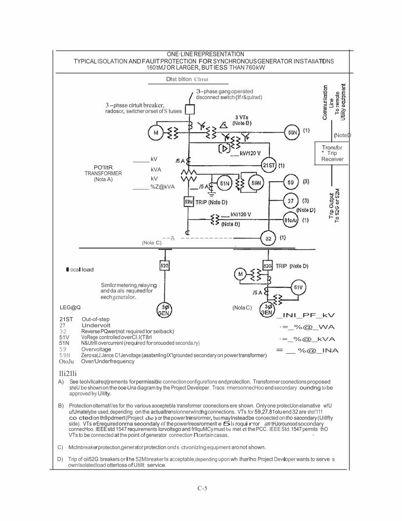
C-5
ONE·LINE REPRESENTATION TYPICAL ISOLATION AND FAUlT PROTECTION FOR SYNCHRONOUS GENERATOR INSTAllATOI NS
160'tMJ OR LARGER,BUT lESS THAN 760 kW
Dlst bltlon Clrrut
3-phss:e clrtult breaker, radosor, switcher orset of S tuses
3- phase gang operated disconnect switch (If r&qulrad)
(NoteD
PO'IItR
TRANSFORMER (Nota A)
kV
kVA
kV
%Z@kVA
Tronsfor ' Trip Receiver
(Nola C) --A ---------------
local load
LEG@Q
21ST 27 32 51V 51N
Simllcr metering,relaying and da als required for eech generalor.
Out-of-step Undervolt Reverse PQwer(not required lor seiback) VoRege controlled overCl.I(T8rl N&Utrlll overcurrenl (required for orouoded seconda.ry)
(Nola C)
_INI_PF_kV ·=_%@_WA ·=_%@_kVA
59 59N OtoJu
lli2lli
Overvoltage Zero sa(J.Jence C1Jervoltage (asstxnlngIX'Igrounded secondary on power transformer) Over/Underfrequency
= %@_INA
A) See teolvllcalreqtjrements for permissible connection oonfigure!lons end prolecllon. Transfonner coonections proposed sheU be shown on the ooe-Una diagram by the Project Developer. Traos rmeroonnecHoo end secondary oundng to be approved by Ullllty.
B) Protection olternati\'es for tho various aooeptebla transformer cooneclions ere shown. Only one prolecUon elamatlve w!U
u!Umatelybe used,depending on the actualtrenslonnerwlndnl g connections. VTs for 59,27,81olu end 32 are sho\'111 co cted on th9pdmert (Project de) or the power trensrormer, but mayInsteadbe conoected on tho saoondary (Uillfty side). VTs erErequired onrna seoondaly ot the powerlreosrormerIt e 5Is roquirror an tHJorounood socondary connecHoo. IEEE std 1547 requirements lorvoltsgo and frllquMCy must be met et the PCC. IEEE Std. 1547 permits thO VTs to be connected at the point of generator connection ncertain casas. ·
C) Mclnbreakerprotection,generator protection ond s ctvonlzlng equpment aro not shown.
D) Trip of oii52G breakers orIhe 52Mbreaker Is acceptable,depending upon wh lharlho Project Developer wants to serve s
own Isolated load otterloss of Utillt service.

C-6
ONE-LINE REPRESENTATION TYPICAL ISOLATION AND FAULT PROTECTION FOR SYNCHRONOUS GENERATOR INSTALLATIONS
750WJ ORLARGER, BUT LESS TH.MI 2MW
[)(slr1Wlon Circuit
3-phase circuit breek&r, rttcloser, swllchor or ot ot 3 fUses
3-phese gong oporelod disconnect switch (if reqt.ired)
(Notoo
PO'WER TRANSFORMER
(Note A)
__ kV
kVA kV
%!@INA
(No o C)
(1)
Transfer
Trtp Receiver
Looe!Load
Sfmller metering, relaying end data Is required for eech genero!or.
LEGEND (Note C)
_kW PF kV
21ST 27 32 51V 51N 59 59N 8fo/u
out-or-step Undervol!aoe Reven;e Powcr(nol required for seUbacl<) Voltage conlrotle<1ovorwrrent Neutrel ovorourrant (roqurrod tor grounood secondary) overvollag& Zero sequence overvoltage (assumingI.KlgroiXIded second81)' on powertraosrormer) ovor/Undecfrt quonoy
Xg" _%@_kVA
Xu' = %@_kVA
X., =_% @_kVA
A) See tectncalroqliromonts brpermissible connection configurations and prolectlon. TransConnor connec(lons proposed shabl e sho'r'm on the ooo-tlna diagram by theProject Developer. Trensf:lrmerconnection and secondary grouoong to be approved by Utility.
!_B) Prot.ectton eltemetf.res for the various acceptable transformer connectlons are shown. Only one protecllon e:tematiVe will
ui!lmelely be used,depenclnQ on the edueltrenslormerwlldino connections. vrs ror 59,27, 81o/u and 32 ere &hovm eo;> ecled onthe pclmary (Pro)oot side)of thO powor transformer, bi..t may Instead be comeded on lhEI secondllfY (UUiiy side). vrs ere requi'ed on tha secondary of the power transformerIt a 59N Is required for en ungrounded socondfl(}' !Xlf1.!lQciiOn.IEEE std 1547 requirements tor voltage and frequency must be met et lhe PCC. IEEE Sid.1547 permns1M
r{∙; .·VT!ito be comected althO point of generator connection h certain cases. I : }<;∙:, ,I,
. ;fSl.'· ¥nbreekerprotecUoo,generator protection end syndvO!izlno eq!Jpmenlare not shoo'll. :,<o_r J·:·.•=·•' ... . '
. f-fQl_ZJ!JP.f E!ll.52G breakers orthe 52M breal<orls acceptable, depending uponrlflolher he Project Developer wants to serve its - l :ht:${0\'inlsolaled load anerloss of UUIservice.

C-7
ONE-LINE REPRESENTATION TYPICAL ISOLATOI N AND FAULT PROTECTION FOR SYNCHRONOUS GENERATOR INSTALLATIONS
2MWOR LARGER
Dlstribi.Aion CircUt
3-phase gang operated dscoMed mltch f required)
3 -phase clrcut breaker, redosor, sviltdler or set ot 3 fuses
POIllER TRMSFORMER
{Note A)
I<V __ kVA
kV
%Z@INA
(NoteC)
(1)
(NoteD Transror
Trip Receiver
LooelLoad
Sfmllarmeleflng,relaying and deta Is raqufrod for each oenerfllor.
LEGEND (Note C)
__ INV _ PF _ kV
21ST 27 32 51V 51N 50 59N 61Q/u
llilru
Out-of-step Undervolteoe Reveroe Power (not requri ed for saUback) Voftege controlled ovorCU'T'Elnt Neutralovercurront (requtnd for grOUlde<t socondety) Overvoltege Zero SO J.Jence overvollege (e!lstxnlng ungroll1d9d secQndefY on power transformer) over/Underfr quenoy
- -= --%@ _ A ·=_ %@_INA
X.. =_ %@_ INA
A) See techrJctlrequirements lor permissible comedlon conilgurallcns endprolecllon. Transformercon cllons proposed shall be shown on lhe one-line d!agrem by the Project Dweloper. Trans rmer connection end secondety groun ng tobe approved by U!Jity.
B) Protection altemaliotes ror the venous acceptable transformer connecllons are shown. Only one pcotecUon e emetrve wiU ultimately be used,depending on the actuellrenstormer winding roMecllons. VTs for 59,27, e1Q/u end32 are shown ronnected on the primary (Project side)of the power tmnsformer, but mayInstead be connected on the secondacy(UUily side). VTs ere required on the secondary ot the power trensfOllller Ite 59N Is required for en lflground&d 9condOlY conneoUon. IEEE std 1547 r quhments for voltage end rre uencymust be met at the PCC. IEEE Std.1547 permls the VTs_to be comected at the point or generetOf connection i"l certsnOilS&s.
C) MainbrookerprolecUon,ganerotor protactol n end s chronlzlng eqi.Apment ere not 'hown.
D) Tr1p or aii52G bfaakers or the 52M breakerIs acceptable, depending upon Whether the Project Developer wants to &ervo its ownlsolalodload sfterloss of UUii! service.

D-1
APPENDIX D
INTERCONNECTION STUDY AGREEMENT

D-2
BOARD OF WATER & LIGHT INTERCONNECTION STUDY AGREEMENT FOR GENERATOR CONNECTION
WHEREAS, proposals to construct or upgrade , a Project which will be operated in parallel with and interconnected to the Board of Water & Light’s (BWL) electric system must be reviewed by the BWL to determine how it will impact the BWL electric system.
WHEREAS, on , the BWL received from , the Project Developer, a Generator Interconnection Application.
WHEREAS the BWL has determined that an Interconnection Study is necessary to determine
whether the BWL electric system can accommodate the requested interconnection.
NOW, THEREFORE, in consideration of the mutual covenants and agreements herein set forth, the BWL and , the Project Developer, agree as follows:
1. The BWL shall complete an Interconnection Study in accordance with the BWL Generator Interconnection Requirements and this Agreement.
2. The BWL is permitted to charge the Project Developer for an Interconnection Study. The charges shall not exceed the lesser of either of the following:
(a) 5% of the estimated total cost of the Project or, (b) $10,000
The BWL shall not charge the Project Developer, if the Project’s aggregate export capacity is less than 15% of the line section peak load and the Project does not contribute more than 25% of the maximum short circuit current at the point of interconnection. The Project Developer will be billed for the cost of the Interconnection Study at the conclusion of the Interconnection Study.
3. The Project Developer, is to return this executed Interconnection Study Agreement to the BWL as soon as possible. The interconnection process will not proceed until the fully executed Interconnection Study Agreement is received.
4. The BWL shall supply a copy of the completed Interconnection Study to the Project Developer.
5. Any notice or request made to or by either Party regarding this Agreement shall be made to the representative of the other Party, or its designated agent, as indicated below.

D-3
Joint Agreement Signatures:
Name: Name: BWL Project Manager Project Developer
Company: Board of Water & Light Company: Address 1: PO Box 13007 Address 1: Address 2: Lansing, Michigan 48901-3007 Address 2:
(Signature) (Signature)
(Title) (Title) Date: Date:

E-1
APPENDIX E INTERCONNECTION &
OPERATION
AGREEMENT

E-2
BOARD OF WATER & LIGHT AGREEMENT FOR
PARALLEL OPERATION OF APPLICANT GENERATORS
THIS AGREEMENT, made this day of by an between
a commercial customer, hereinafter referred to as the "APPLICANT" and the "BOARD OF WATER AND LIGHT" a municipal utility operating under the laws of the State of Michigan, hereinafter referred to as the "BOARD". WITNESSETH: WHEREAS APPLICANT has developed an electrical generating facility. WHEREAS THE APPLICANT desires that the BOARD allow parallel operation of the APPLICANT'S electrical generating facility with the BOARD'S electrical system. NOW, THEREFORE, in consideration of the mutual promises and covenants herein made between the APPLICANT and the BOARD, it is hereby agreed: 1. TERM OF AGREEMENT This Agreement shall be binding upon execution by the parties and unless otherwise cancelled shall remain in effect as long as the applicant’s generating facility is interconnected to the BOARD'S electrical system. 2. RESPONSIBILITY AND AUTHORITY
A. The APPLICANT shall be responsible to implement the operating guidelines contained in this
Agreement and abide by the BOARD'S existing Electric Rates, Rules and Regulations for Electric Service. The Applicant acknowledges that said Rates, Rules and Regulations may be revised from time to time, and hereby agrees to be bound by said revisions.
B. The APPLICANT shall notify the BOARD prior to installation and testing of any generating
units. And the APPLICANT shall not start up and test any generating unit prior to obtaining written approval from the BOARD, if such testing is to be done in parallel with the BOARD'S electrical system.
C. The APPLICANT shall furnish the BOARD with, and obtain BOARD approval of, current
drawings for the interconnection and protective relaying schemes to be used by the APPLICANT.
D. The APPLICANT acknowledges that it may incur a penalty for additional reactive power
(VARS) that is required for the excitation of the induction generators if the APPLICANT'S system power factor falls below 85%. The penalty will be applied in accordance with the BOARD'S Electric Rates, Rules and Regulations for Electric Service. The APPLICANT also acknowledges that capacitors or other devices added to its electrical system for the purpose of

E-3
providing power factor correction may increase the chances that the induction generator experiences "self excitation". This condition is known to be very unstable and may cause system overvoltages and/or equipment damage during automatic bus transferring for line outages. If this condition is sufficiently serious the BOARD may, in its discretion, require the APPLICANT to disconnect the capacitors or other devices at the APPLICANTS site or in the alternative the BOARD may elect to move any existing capacitors on their own distribution feeders at the APPLICANT'S expense.
E. The APPLICANT shall pay for all costs associated with any alteration of the BOARD'S
equipment required for proper operation of the APPLICANT'S generating facility in parallel with the BOARD'S electrical system. The APPLICANT will also be liable to pay costs of future alterations due to changes in operating status, safety or adverse effects on the BOARD'S system or those of its customers.
F. Should the parallel operation of the APPLICANT'S generating facility cause interference with,
affect voltage, frequency or harmonic content of, the BOARD'S system or those of its customers, the APPLICANT shall upon notice discontinue parallel operation until the condition has been corrected.
G. The APPLICANT shall be liable for any injury or damage caused to the BOARD'S employees or
equipment as a result of operation of APPLICANT'S generating facility. H. The BOARD assumes no liability for damage to the APPLICANT'S equipment or employees as
a result of operating under this agreement. I. The APPLICANT agrees to indemnify and hold harmless the BOARD, its agents, officers, and
employees, to the extent permitted by law, during the entire term of the Agreement from any and all loss or damage to property, or injury to or death of any person and from all suits, claims, liability or demands, however caused, resulting from the use of the herein generating facility, and shall settle, adjust, or defend the same at its sole cost and expense, including, but not limited to attorney fees; provided, however, that said duty to defend, indemnify and hold harmless is conditioned upon the notification of the APPLICANT by the BOARD of any such suit, claim, liability, demand, etc., within ten (10) days of the same being made upon the BOARD; and further provided that the APPLICANT shall not be required to indemnify the BOARD, its agents, officers, and employees for damage to property or injury or death to persons caused by the sole negligence of the BOARD, its agents, officers or employees. The provisions of this section shall not give any third party any claims to which he/she or it would not otherwise be entitled. The APPLICANT'S obligation hereunder shall survive cancellation or termination of this agreement for damages to property or injury or death to persons incurred before the termination or cancellation.
J. If the APPLICANT does not meet all of the above requirements, the BOARD may require
termination of parallel operation. Failure to terminate parallel operation when required shall be cause for the BOARD to interrupt electric service to the APPLICANT. The BOARD may also give written notification of cancellation of this AGREEMENT.
E-4
3. OPERATION OF APPLICANT'S GENERATING FACILITY
A. The APPLICANT'S generators shall be operated so as not to feed power back into the BOARD'S Electrical System. The BOARD will not be billed and shall not be responsible to pay for any power inadvertently delivered by the APPLICANT to the BOARD'S system.
B. All oral operating communications between the parties shall be conducted through the BOARD'S
Brush Electrical System Operating Center (B.E.S.O.C.). APPLICANT agrees to maintain direct phone service from the local phone company so that operating instructions from the BOARD can be given to the APPLICANT or its designated operator.
C. APPLICANT shall maintain daily operating communications with the BOARD'S Brush
Electrical System Operating Center. The operating communications shall include, but not be limited to, system paralleling or separation, scheduled and unscheduled shutdowns, equipment clearance, levels of operating voltage and power factors.
D. APPLICANT shall keep a daily operations log for its generating facility which shall include
information on generator output, unit availability, maintenance outages, circuit breaker trip operations and any significant events related to operation of the generating facility. APPLICANT shall send a copy of this log to the BOARD'S Electric System Operations Department, or his/her designee every 6 months and shall make the log available for review upon demand.
E. APPLICANT agrees to supply and timely update the BOARD'S Brush Electrical System
Operating Center of the following:
1. The current names and phone numbers of the personnel responsible for operating and maintaining the generating facility and any changes made to this list.
2. Any emergency situations which may adversely affect the BOARD’S electric system
integrity, or any requirement that BOARD de-energize a portion of the APPLICANT'S system under its control.
3. Any change in the mechanical or electrical condition that may affect capacity or the
reliability of the APPLICANT'S generating facility.
4. Immediately upon discovery, any BOARD required interconnection relay that is either inoperable or operating improperly.
5. Immediately upon discovery, any circuit breaker that has operated by a BOARD required
interconnection relay, along with the relay targets that caused the circuit breaker to operate.
6. Plans to manually parallel with or separate from the BOARD system and the times of
actual manual parallels and separations. Emergency separations shall be reported as soon as conditions permit.

E-5
F. In the event APPLICANT wishes to perform work on its own generating facilities which would normally be energized by a BOARD controlled source of energy, it shall provide written notice to the Brush Electrical System Operating Center of the need for a clearance. The BOARD shall provide clearance in accordance with its current procedure of opening, locking and tagging the interconnection disconnect device(s) to APPLICANT'S facilities from BOARD sources of energy, and to establish the interconnection disconnect device as a visible break according to usual BOARD procedures.
G. Unless an emergency exist, APPLICANT shall give 72 hours (three working days) notice when
requesting a clearance and shall supply the BOARD'S Brush Electrical System Operating Center with the following information:
1. Nature of work to be performed.
2. Date and time work will begin.
3. Date and time work will be completed.
4. Apparatus to be cleared and the clearance points required.
5. Name of person in charge of the work.
6. Whether protective grounds will be installed.
H. The parties agree to the following:
1. On request, BOARD will open interconnection disconnect device(s) necessary to clear APPLICANT'S equipment from BOARD supply sources in the following manner:
a. BOARD will install and remove tags on any open interconnection
disconnect switch or draw out breaker used as a clearance point.
b. Where BOARD must have the interconnection disconnect switch open for a clearance point, a qualified BOARD employee will observe that the switch is open, lock it open with a BOARD lock, disconnect the control voltage and attach filled-out tags to indicate it is a clearance point. If no provision for locking is provided, all three disconnects will be tagged with a properly completed tag. If a draw out breaker is the only means of disconnect, the breaker will be racked out and tagged with a properly completed tag.
c. BOARD assumes no liability for APPLICANT'S equipment energized
from generating facility sources or by any other means. APPLICANT agrees that work is performed at its own risk. APPLICANT shall take all necessary steps to ensure that work is conducted in compliance with all

E-6
applicable federal, state and local laws and regulations and in a manner which does not endanger the safety of persons or equipment.
I. APPLICANT agrees to the following conditions regarding a clearance requested by BOARD:
1 APPLICANT shall provide the BOARD emergency access to the interconnect device by
either having a key, secured at Brush Electrical System Operating Center or a BOARD key box mounted at the APPLICANT'S facility.
2. The same clearance and tagging procedures as in section 3.8 above will be used.
3. APPLICANT will not manually or automatically re-energize the transformer or circuits
involved prior to receiving approval from Brush Electrical System Operating Center.
4. The APPLICANT shall install and maintain warning signs on the main control panel and at each remote operating location where the APPLICANT has remote closing capability to accommodate a clearance procedure.
4. MAINTENANCE OF APPLICANT-OWNED INTERCONNECTION EQUIPMENT
A. All BOARD required interconnection devices must remain in service with relay settings as recorded on the "Board Relay Setting and Test Report Form". Proposed changes in relay settings must be submitted in writing to the BOARD for approval. Any modification of the existing interconnection or protection scheme requires prior written approval of the BOARD'S Electric System Protection Engineer or his/her designee.
B. BOARD required interconnection equipment owned by APPLICANT shall be periodically tested
by BOARD personnel at the APPLICANT'S expense. The APPLICANT shall schedule and provide the BOARD access for testing at reasonable hours. Copies of equipment test reports shall be forwarded to the BOARD'S Superintendent of System Operation or his/her designee and approved before APPLICANT may resume parallel operation. APPLICANT shall comply with the following requirements for BOARD required interconnection equipment:
1. Interconnection relays shall be tested at intervals not to exceed three years.
2. Individual relays shall be secondary bench tested by applying the appropriate currents,
voltages or frequencies. The relays must be tested at their specified setting to verify the minimum operating point at which relay will actuate (Minimum Pickup).
3. Lamicoid name plates shall be installed by APPLICANT adjacent to all BOARD-
required interconnection relays. Each relay name plate shall include the device number and the relay's function.
4. Non-revenue meter calibration shall be checked and all current transformers and potential
transformers shall be tested at intervals not to exceed six years. Current transformers shall be primary or secondary ratio tested. If the current transformers are secondary ratio tested, a voltage ratio must be performed to verify turns ratio.

E-7
5. SIGNATURES The said parties do hereby agree to the full performance of the covenants herein contained and the APPLICANT acknowledges to understand and agree to the provisions set forth. In witness whereof, the parties have caused this Agreement to be executed by their duly authorized representatives and effective as of the last date signed by both parties below.
WITNESS LANSING BOARD OF WATER AND LIGHT
Title: General Manager
Title: Corporate Secretary
DATE:
WITNESS CUSTOMER/OWNER
Title:
Title:
DATE:
Approved as to form only by:
Title: Legal Counsel

F-1
APPENDIX F
PROCEDURE PROGRESS TRACKING & STATUS
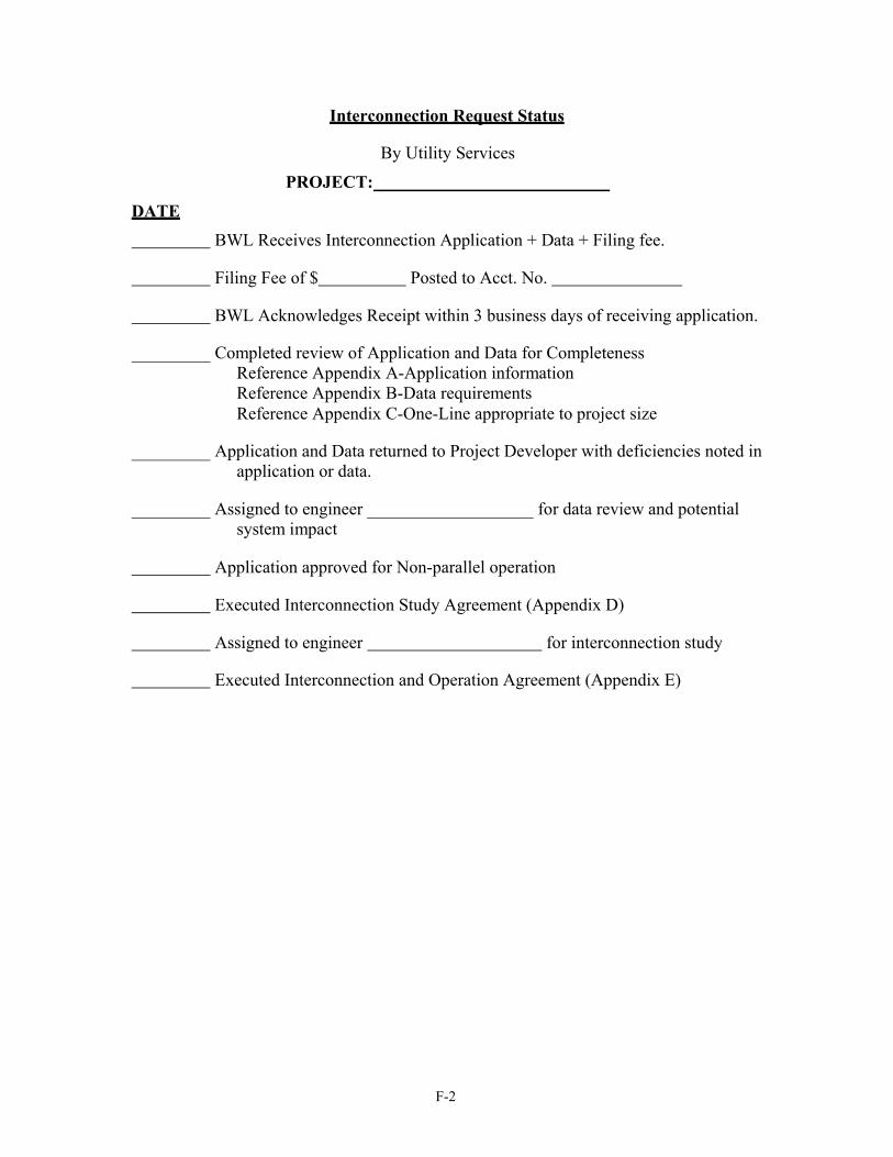
F-2
Interconnection Request Status DATE
By Utility Services
PROJECT:
BWL Receives Interconnection Application + Data + Filing fee.
Filing Fee of $ Posted to Acct. No.
BWL Acknowledges Receipt within 3 business days of receiving application.
Completed review of Application and Data for Completeness Reference Appendix A-Application information Reference Appendix B-Data requirements Reference Appendix C-One-Line appropriate to project size
Application and Data returned to Project Developer with deficiencies noted in application or data.
Assigned to engineer system impact
for data review and potential
Application approved for Non-parallel operation
Executed Interconnection Study Agreement (Appendix D)
Assigned to engineer for interconnection study
Executed Interconnection and Operation Agreement (Appendix E)