Embed Size (px)
Citation preview

By Authority OfTHE UNITED STATES OF AMERICA
Legally Binding Document
By the Authority Vested By Part 5 of the United States Code § 552(a) and Part 1 of the Code of Regulations § 51 the attached document has been duly INCORPORATED BY REFERENCE and shall be considered legally binding upon all citizens and residents of the United States of America. HEED THIS NOTICE: Criminal penalties may apply for noncompliance.
Official Incorporator:THE EXECUTIVE DIRECTOROFFICE OF THE FEDERAL REGISTERWASHINGTON, D.C.
Document Name:
CFR Section(s):
Standards Body:
e
International Organization for Standardization
49 CFR 173.301b(c)(1)
ISO 10297: Gas cylinders--Refillable gascylinder valves--Specification and typetesting


INTERNATIONAL STANDARD
ISO 10297
First edition 1999-05-01
Gas cylinders - Refillable gas cylinder valves ........ Specification and type testing
Bouteilles a gaz - Robinets de bouteilles a gaz rechargeables -Specifications et essais de type
~:::~~~~:~
~ISO-~· --... - .. -- -- -- --_. _._ .. --~-- -- --:::=== .... - ~ Reference number
ISO 10297:1999(E)

ISO 10297:1999(E)
Contents Page
1 Scope ........................................................................................................................................................................ 1
2 Normative references .............................................................................................................................................. 1
3 Definitions and symbols ......................................................................................................................................... 2
4 Valve requirements .................................................................................................................................................. 3
5 Prototype valve test ................................................................................................................................................. 7
6 Marking ................................................................................................................................................................... 16
7 Test report ........................................................................................ ,." .............................. , ............. " .................... 16
Annex A (informative) Example of test sequence .................................................................................................. 17
Annex B (normative) Valve impact test. .................................................................................................................. 18
Annex C (normative) Endurance test ...................................................................................................................... 20
Bibliography .............................................................................................................................................................. 24
© ISO 1999
All rights reserved. Unless otherwise speCified, no part of this publication may be reproduced or utilized in any form or by any means, electronic or mechanical, including photocopying and microfilm, without permission in writing from the publisher.
International Organization for Standardization Case postale 56 • CH-1211 Geneve 20 • Switzerland Internet [email protected]
Printed in Switzerland
©ISO ISO 10297:1999(E)
Foreword
ISO (the International Organization for Standardization) is a worldwide federation of national standards bodies (ISO member bodies). The work of preparing International Standards is normally carried out through ISO technical committees. Each member body interested in a subject for which a technical committee has been established has the right to be represented on that committee. International organizations, governmental and non-governmental, in liaison with ISO, also take part in the work. ISO collaborates closely with the International Electrotechnical Commission (IEC) on all matters of electrotechnical standardization.
International Standards are drafted in accordance with the rules given in the ISO/IEC Directives, Part 3.
Draft International Standards adopted by the technical committees are circulated to the member bodies for voting. Publication as an I nternational Standard requires approval by at least 75 % of the member bodies casting a vote.
International Standard ISO 10297 was prepared by Technical Committee ISOITC 58, Gas cylinders, Subcommittee SC 2, Cylinder fittings.
Annexes Band C form an integral part of this International Standard, annex A and the Bibliography are for information only.
iii

i 1
1
1
1
1
1
1
1
1
1
1
1
1
1
1
1
1
1
1
1
1
1
1
1
1
1
1
1
1
1
1
1
1
1
1
1
1
1
1
1
1
1
1
1 I
INTERNATIONAL STANDARD © ISO ISO 10297:1999(E)
Gas cylinders ......... Refillable gas cylinder valves -Specification and type testing
1 Scope
This International Standard specifies requirements for refillable gas cylinder valves and the method of testing such valves for type approval.
This International Standard is applicable to valves to be fitted to gas cylinders of up to 150 I water capacity, intended to convey compressed, liquefied or dissolved gases.
This International Standard is only applicable to valves operated by a hand wheel or a key.
This International Standard is not applicable to valves for breathing equipment, fire extinguishers, cryogenic equipment or liquefied petroleum gas (LPG).
Additional specific requirements for valves fitted with pressure-reducing, pressure-retaining and non-return devices are not covered by this International Standard.
2 Normative references
The following normative documents contain provisions which, through reference in this text, constitute provisions of this International Standard. For dated references, subsequent amendments to, or revisions of, any of these publications do not apply. However, parties to agreements based on this International Standard are encouraged to investigate the possibility of applying the most recent edition of the normative documents indicated below. For undated references, the latest edition of the normative document referred to applies. Members of lEe and ISO maintain registers of currently valid International Standards.
ISO 188, Rubber, vulcanized or thermoplastic - Accelerated ageing or heat-resistance tests.
I SO 1817, Rubber, vulcanized - Determination of the effect of liquids.
ISO 5145, Cylinder valve outlets for gases and gas mixtures - Selection and dimensioning.
ISO 10156, Gases and gas mixtures - Determination of fire potential and oxidizing ability for the selection of cylinder valve outlets.
ISO 10920, Transportable gas cylinders - 25E taper thread for connection of valves - Specification.
ISO 11114-1, Transportable gas cylinders - Compatibility of cylinder and valve materials with gas contentsPart 1: Metallic materials.
ISO 11114-2, Transportable gas cylinders - Compatibility of cylinder and valve materials with gas contentsPart 2: Non-metallic materials.
ISO 11114-3, Transportable gas cylinders - Compatibility of cylinder and valve materials with gas contentsPart 3: Autogenous ignition test in oxygen atmosphere.
I SO 11116-1, Gas cylinders - 17E taper thread for connection of valves to gas cylinders - Part 1: Specifications.
I SO 11117, Gas cylinders - Valve protection caps and valve guards for industrial and medical gas cylindersDesign, construction and tests.
1

ISO 10297:1999(E) ©ISO
3 Definitions and symbols
For the purposes of this International Standard, the following definitions and symbols apply.
3.1 working pressure Pw settled pressure, at a uniform temperature of 15 °e, for a full gas cylinder
3.2 operating pressure Po varying pressure which is developed in a cylinder during service
3.3 valve test pressure Pvt for permanent gases:
Pvt = 1,2 xPw
For liquefied gases and dissolved gases under pressure (for example, acetylene), Pvt shall be at least equal to the minimum test pressure of the cylinder quoted in the relevant transportation regulation for that gas or gas group.
3.4 external tightness tightness to atmosphere (leakage in and/or leakage out) when the valve is open (see Figure 1)
Key p = internal pressure
Pa = atmospheric pressure
1 Leakage in
2 Leakage out
Figure 1 - External tightness
2

©ISO ISO 10297:1999(E)
3.5 Internal tightness tightness across the valve seat (leakage in and/or leakage out) when the valve is dosed (see Figure 2)
Key p = internal pressure
Pa = atmospheric pressure
1 Leakage in
2 Leakage out
3.6 minimum closing torque Tc
1
Figure 2 - Internal tightness
minimum closing torque applied to valve operating mechanism necessary to obtain the internal tightness
3.7 resistance torque maximum closing torque applied to valve operating mechanism which the valve can withstand without suffering damage
3.8 valve operating mechanism manually rotated device, which doses and opens the valve orifice
4 Valve requirements
4.1 General
Valves shall operate satisfactorily over the full range of service temperatures, from - 20°C to + 65 DC. The range may be extended for short periods (e.g. during filling). VVhere higher or lower service temperatures are required for longer periods, the purchaser shall specify this.
Valves shall be capable of withstanding any mechanical stresses or chemical attack they may experience during normal service.
Valves shall be cleaned to meet the requirements of the intended service.
3
ISO 10297:1999(E) ©ISO
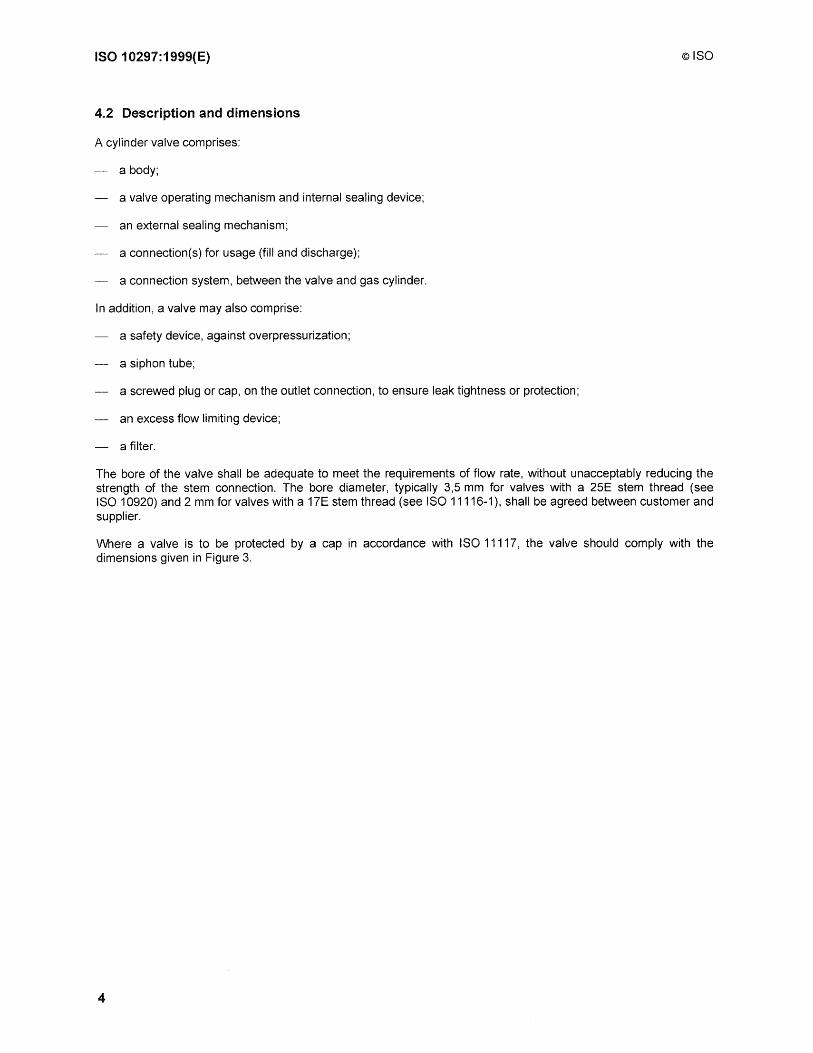
4.2 Description and dimensions
A cylinder valve comprises:
a body;
a valve operating mechanism and internal sealing device;
an external sealing mechanism;
a connection(s) for usage (fill and discharge);
a connection system, between the valve and gas cylinder.
In addition, a valve may also comprise:
a safety device, against overpressurization;
a siphon tube;
a screwed plug or cap, on the outlet connection, to ensure leak tightness or protection;
an excess flow limiting device;
a filter.
The bore of the valve shall be adequate to meet the requirements of flow rate, without unacceptably reducing the strength of the stem connection. The bore diameter, typically 3,5 mm for valves with a 25E stem thread (see ISO 10920) and 2 mm for valves with a 17E stem thread (see ISO 11116-1), shall be agreed between customer and supplier.
Where a valve is to be protected by a cap in accordance with ISO 11117, the valve should comply with the dimensions given in Figure 3.
4

©ISO ISO 10297: 1999(E)
r ~ 32,5 mm
h ~ 90 mm
R ~ 38 mm
L ~ 125 mm
, r __ _
NOTE 1 h represents the height between the lower part of the valve and the point at which the overall radius of the valve is
equal to the radius of the handwheel when the radius of the valve is greater than the radius of the handwheel.
NOTE 2 When the axes of the valve, the valve stem thread and handwheel do not coincide the distance between the two
axes should be added to r.
NOTE 3 L is the maximum length of a valve in the closed position when not fitted to a cylinder.
NOTE 4 R should be measured to the part of the valve furthest from the stem axis and includes any outlet plugs or caps if
fitted.
Figure 3 - Maximum dimensions for gas cylinder valves, protected by a cap
4.3 Materials
Metallic and non-metallic materials in contact with the gas shall be chemically and/or physically compatible with the
gas, under all intended operating conditions (see ISO 11114-1 and ISO 11114-2).
Compatibility of materials with oxygen and other oxidizing gases, ignition resistance of materials and lubricants,
shall be established by an appropriate test procedure (see ISO 11114-3).
Valves for acetylene may be manufactured from copper-based alloys if the copper content does not exceed 70 %
(mlm). The manufacturer shall not use any procedure resulting in copper enrichment of the surface. Silver content of
alloys shall be limited for acetylene valves. The acceptable limit varies between 43 % (mfm) and 50 % (mlm),
depending on the composition of the alloy.
Non-metallic sealing material for use with air, oxygen and oxygen enriched gases, shall be capable of withstanding
an ageing sensitivity test in accordance with ISO 188.
Non-metallic sealing material in valves shall be capable of withstanding corrosive media tests in accordance with
ISO 1817.
5
ISO 10297:1999(E) ©ISO
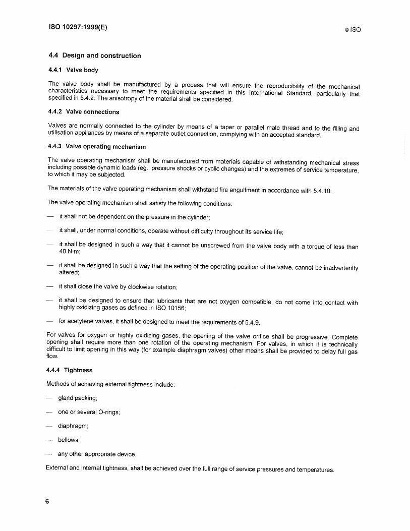
4.4 Design and construction
4.4.1 Valve body
The valve body shall be manufactured by a process that will ensure the reproducibility of the mechanical characteristics necessary to meet the requirements specified in this International Standard, particularly that specified in 5.4.2. The anisotropy of the material shall be considered.
4.4.2 Valve connections
Valves are normally connected to the cylinder by means of a taper or parallel male thread and to the filling and utilisation appliances by means of a separate outlet connection, complying with an accepted standard.
4.4.3 Valve operating mechanism
The valve operating mechanism shall be manufactured from materials capable of withstanding mechanical stress including possible dynamic loads (eg., pressure shocks or cyclic changes) and the extremes of service temperature, to which it may be subjected.
The materials of the valve operating mechanism shall withstand fire engulfment in accordance with 5.4.10.
The valve operating mechanism shall satisfy the following conditions:
it shall not be dependent on the pressure in the cylinder;
it shall, under normal conditions, operate without difficulty throughout its service life;
it shall be designed in such a way that it cannot be unscrewed from the valve body with a torque of less than 40 N'm;
it shall be designed in such a way that the setting of the operating position of the valve, cannot be inadvertently altered;
it shall close the valve by clockwise rotation;
it shall be designed to ensure that lubricants that are not oxygen compatible, do not come into contact with highly oxidizing gases as defined in ISO 10156;
for acetylene valves, it shall be designed to meet the requirements of 5.4.9.
For valves for oxygen or highly oxidizing gases, the opening of the valve orifice shall be progressive. Complete opening shall require more than one rotation of the operating mechanism. For valves, in which it is technically difficult to limit opening in this way (for example diaphragm valves) other means shall be provided to delay full gas flow.
4.4.4 Tightness
Methods of achieving external tightness include:
gland packing;
one or several a-rings;
diaphragm;
bellows;
any other appropriate device.
External and internal tightness, shall be achieved over the full range of service pressures and temperatures.
6

©ISO ISO 10297:1999(E)
The external tightness shall be maintained for all positions of the valve spindle, from the opening, to complete closing and during operation.
All sealing devices shall withstand 2 000 opening and closing cycles, at Pvt, without replacement of the sealing device. Adjustment is permitted.
The minimum gauge pressure, during the tightness test, shall be 0,1 bar. VVhere the valve is not intended for use with inflammable or toxic gases this pressure may be increased to 0,5 bar.
At the customer's request the tightness test may be carried out under vacuum.
VVhen incorporating diaphragms or bellows, additional gland packings or a-rings, may be used to ensure safety, in case of deterioration of the diaphragms or the bellows. This particularly applies for toxic gases.
The tightness test is normally carried out with air or nitrogen. Valves designated for use with gases lighter than air, or very searching gases (for example carbon dioxide) may be subjected to a test using helium.
For the definition of an inflammable gas see ISO 10156, and for the definition of a toxic gas see annex A of ISO 5145.
4.4.5 leakage rate
The internal or external leakage rate shall not exceed 6 cm3/h at 20°C and 1 013 mbar.
The specified rate may be amended by agreement and subject to special applications, eg., for valves for highly toxic or high purity gas service, a lower leakage rate may be specified.
4.4.6 Operating torque
For handwheel operated valves, with a handwheel diameter of 65 mm, the closing torque to obtain internal tightness, shall be 7 N'm or less. For certain valves (for example key operated or diaphragm valves) this torque may be higher. The size of the handwheel, or equivalent operating device, shall be appropriate for the required closing torque (see 5.4.3.2 and 5.4.6).
The torque necessary for the complete closing and opening of the valve, shall not increase significantly during the valve's service life (see 5.4.4).
5 Prototype valve test
5.1 General
Before valves are introduced into service, they shall be submitted for prototype approval (see 5.2 and 5.3). A prototype approval is valid for a given family of valves, having the same basic design.
Variations to connections do not require further prototype testing.
Changes to the internal components for reasons of gas/material compatibility (for example 'a' ring, packing, diaphragm, spindle, lubricant) constitute a type variant within the given family.
Type variants require repetition of the relevant parts of the type test.
Changes of the basic design dimensions of components or changes of valve body material, constitute a new family and require the full type test.
7

ISO 10297:1999(E) ©ISO
5.2 Documents
The manufacturer shall make available to the test authority, the following documents:
a set of drawings consisting of the general arrangement, parts list, material specifications and detail drawings. Any type variant, within the given family, shall be clearly identified;
description of valve and method of operation;
information on the field of application of the valve (gases and gas mixtures, pressures, use with or without valve protection device, etc). It shall be clearly indicated which gases and gas mixtures can be used with each type variant;
certificates of material compatibility as required.
5.3 Test valves
A minimum of nine sample valves are required (more samples may be necessary, depending on the number of type variants to be tested):
a) one sample (No.1) for the hydraulic pressure test;
b) samples for tightness tests and endurance test as follows:
1) when no type variants are specified, five samples of the basic specification shall be tested. (Nos. 2 to 6);
2) when one type variant (a) is specified, three samples (Nos 2, 3, 4) of the basic specification and two samples (Nos. 5a and 6a) of the type variant shall be tested;
3) when two or more type variants (a, b, etc.) are specified, two samples (Nos. 2 and 3) of the basic specification, and two samples of each type variant (Nos. 4a and 5a, 4b and 5b, etc.) shall be tested;
c) one sample (No.2) is also used for the fire exposure test;
d) one sample (No.7) for any additional test which may be required;
e) two samples (Nos. 8 and 9) for determination of operating torques.
In addition, for oxygen or highly oxidizing gas service, three sample valves (10n, 11n and 12n) are required for the oxygen pressure surge test and for acetylene service, three sample valves (10m, 11m, and 12m) are required for the internal tightness test after flashback.
5.4 Test procedure
5.4.1 Table of tests
Tests shall be carried out, in accordance with the schedule given in Table 1.
See annex A, for an example of test sequence for a basic design with type variants.
8

©ISO ISO 10297:1999(E)
Table 1 - Sequence of tests (tightness, endurance and fire resistance) for type approval (no variants)
Test Test and sub Condition of Test temperature Valve No. of Total sequence clause No. test valve sample tests/valve No. of
°C number tests
1 Hydraulic 5.4.2 As received 20±5 1 1 1
2 I nternal/external As received 20 ± 5 2a to 6 6b or 8 30b or 40 tightness 5.4.3
3 I nternallexternal From test 20 ±5 2a t06 6b or 8 30b or 40 tightness 5.4.3 sequence 2,
aged at 65°C for 5 days
4 Endurance 5.4.4 From test 20±5 2a to 6 1 5 sequence 3
5 Internal/external From test 20±5 2a to 6 6b or 8 30b or 40 tightness 5.4.3 sequence 4
6 I nternal/external From test 65 ±2,5 2a to 6 6b or 8 30b or 40 tightness 5.4.3 sequence 5
7 Internal/external From test -20 ± 2,5c 2a to 6 6b or 8 30b or 40 tightness 5.4.3 sequence 6
8 Visual From test 20 ± 5 2a to 6 1 5 examination sequence 7
5.4.5
9 Excessive torque As received 20 ± 5 8 and 9 1 2 5.4.6
10 Fire exposure From test 800 to 1 000 2 1 1 5.4.10 sequence 8
a For additional type variants, valve sample numbers and tests will change in accordance with 5.3. b The total number of tests will be 30 without vacuum test and 40 if a vacuum test is required. c For some parts of the world and for certain applications, tests at a lower temperature (e.g. -30°C) shall be considered.
5.4.2 Hydraulic pressure test
For safety reasons this test shall be carried out prior to all other tests.
The hydraulic pressure test shall be carried out under the following conditions:
valve seat in open position;
valve outlet connection sealed;
safety relief devices (where fitted) removed and the opening sealed;
test medium, water or other suitable fluid;
for permanent gases 1,5 x 1,5 Pw;
for liquefied gases 1,5 Pvt;
for dissolved gases, such as acetylene, the test pressure of the valve shall be 450 bar;
test temperature, ambient temperature (20 ± 5) °C;
pressure holding time, 2 min minimum.
The pressure shall be raised continuously and gradually. The prototype valve shall withstand the test, without permanent deformation or rupture.
9
ISO 10297:1999(E) ©ISO
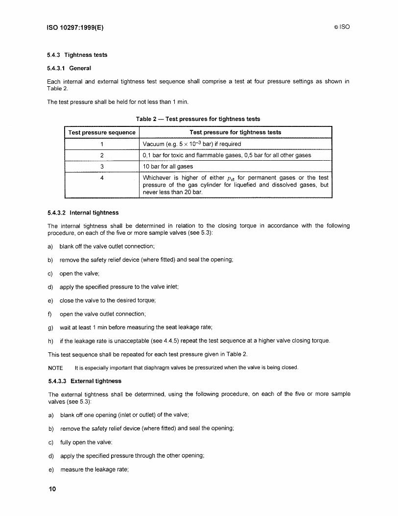
5.4.3 Tightness tests
5.4.3.1 General
Each internal and external tightness test sequence shall comprise a test at four pressure settings as shown in Table 2.
The test pressure shall be held for not less than 1 min.
Table 2 - Test pressures for tightness tests
Test pressure sequence Test pressure for tightness tests
1 Vacuum (e.g. 5 x 10⁻³ bar) if required
2 0,1 bar for toxic and flammable gases, 0,5 bar for all other gases
3 10 bar for all gases
4 VVhichever is higher of either Pvt for permanent gases or the test pressure of the gas cylinder for liquefied and dissolved gases, but never less than 20 bar.
5.4.3.2 Internal tightness
The internal tightness shall be determined in relation to the closing torque in accordance with the following procedure, on each of the five or more sample valves (see 5.3):
a) blank off the valve outlet connection;
b) remove the safety relief device (where fitted) and seal the opening;
c) open the valve;
d) apply the specified pressure to the valve inlet;
e) close the valve to the desired torque;
f) open the valve outlet connection;
g) wait at least 1 min before measuring the seat leakage rate;
h) if the leakage rate is unacceptable (see 4.4.5) repeat the test sequence at a higher valve closing torque.
This test sequence shall be repeated for each test pressure given in Table 2.
NOTE It is especially important that diaphragm valves be pressurized when the valve is being closed.
5.4.3.3 External tightness
The external tightness shall be determined, using the following procedure, on each of the five or more sample valves (see 5.3):
a) blank off one opening (inlet or outlet) of the valve;
b) remove the safety relief device (where fitted) and seal the opening;
c) fully open the valve;
d) apply the specified pressure through the other opening;
e) measure the leakage rate;
10
©ISO ISO 10297: 1999(E)
f) partially close the valve;
g) measure the leakage rate.
If required, action f) and action g) may be repeated for different partial closings.
For test sequence 7 of Table 1, carried out at (-20 ± 2,5) °C, the external leakage rate shall also be measured while the handwheel is being rotated.
5.4.4 Endurance test
An endurance test of 2 000 cycles, consisting of fully opening and closing of the valve, shall be carried out at Pvt·
After each closure the pressure downstream of the seat shall be released to atmosphere. There shall be a pause of at least 6 s at each fully open and fully closed position.
Care should be taken to ensure that, during the test, friction does not cause the valve temperature to significantly exceed that specified in Table 1.
For handwheel valves, the closing torque used during the test shall be 7 N·m. No significant torque shall be applied in the fully open position.
For key-operated or diaphragm valves which require a minimum closing torque (Te) greater than 7 N'm, the torque used during the test shall be equal to 1,5 x Te.
For small valves, with a minimum closing torque of less than 7 N"m, the torque used during the test, shall be twice the minimum closing torque, subject to a maximum of 7 N·m.
For all subsequent tests, the torque used during the endurance test shall not be exceeded.
5.4.5 Visual examination
\M1en the endurance test and the subsequent tightness tests have been completed, sealing elements such as diaphragms, bellows, O-rings, shall be subject to a visual check for unacceptable wear and/or damage.
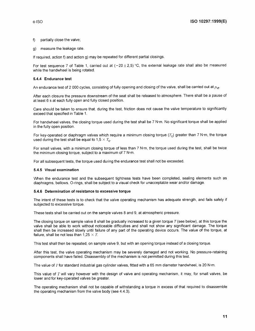
5.4.6 Determination of resistance to excessive torque
The intent of these tests is to check that the valve operating mechanism has adequate strength, and fails safely if subjected to excessive torque.
These tests shall be carried out on the sample valves 8 and 9, at atmospheric pressure.
The closing torque on sample valve 8 shall be gradually increased to a given torque T (see below), at this torque the valve shall be able to work without noticeable difficulties and shall not show any significant damage. The torque shall then be increased slowly until failure of any part of the operating device occurs. The value of the torque, at failure, shall be not less than 1,25 x T.
This test shall then be repeated, on sample valve 9, but with an opening torque instead of a closing torque.
After this test, the valve operating mechanism may be severely damaged and not working. No pressure-retaining components shall have failed. Disassembly of the mechanism is not permitted during this test.
The value of Tfor standard industrial gas cylinder valves, fitted with a 65 mm diameter handwheel, is 20 N·m.
This value of T will vary however with the deSign of valve and operating mechanism, it may, for small valves, be lower and for key-operated valves be greater.
The operating mechanism shall not be capable of withstanding a torque in excess of that required to disassemble the operating mechanism from the valve body (see 4.4.3).
11

ISO 10297:1999(E) ©ISO
5.4.7 Mechanical impact test
If it is not intended for the valve to be protected by a cap or another form of guarding, an impact test shall be carried out on valve sample 7, as described in annex B.
5.4.8 Oxygen pressure surge test
This test shall be carried out for valves used in all applications where the gas or gas mixture has an oxidizing potential greater than that of air (for the definition of oxidizing potential see ISO 10156). For all types of valve the pressure surge test shall be carried out with pure oxygen.
The purpose of the test is to check whether the valve safely withstands an oxygen pressure surge.
Three sample valves, samples 10 to 12, in the "as-received" condition (or lubricated if a lubricant is used for such a valve) shall be tested.
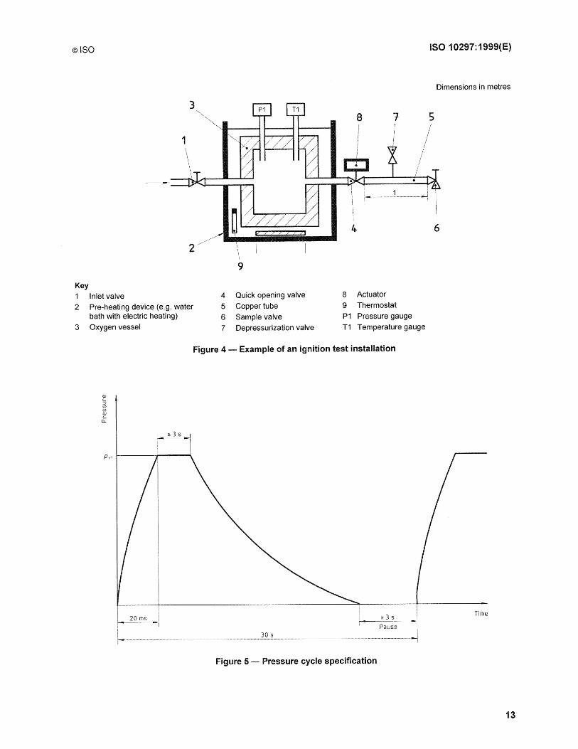
Before the test, the ignition test installation shall be checked for the required pressure rise (for examples of test installation and pressure cycle specification, see Figures 4 and 5). For this purpose the test valve, at the end of the 1 m length of copper tube, is replaced by a reliable pressure gauge.
The maximum pressure at the dead end of the copper tube or tube in monel or any other material with equivalent resistance to oxygen (measured by pressure gauge and recorded on an oscilloscope) shall be achieved within (20_~) ms (time necessary to reach Pvt starting from atmospheric pressure).
Stabilization time at Pvt is not fixed but shall be greater than or equal to 3 s. Before the next pressure surge the system (sample valve and copper tube) shall be depressurized down to atmospheric pressure. Stabilization time at atmospheric pressure is not fixed but shall be greater than, or equal to 3 s.
The total time of the pressure cycle shall be 30 s, as illustrated in Figure 5. Total time is the time between the beginning of two consecutive pressure surges.
For calibration purposes, heated oxygen at (60 ± 3) °C shall be used.
The quality of oxygen shall be:
minimum purity 99,5 % (Vl\f);
hydrocarbon content :'S 0,001 % (VIV).
Each test shall be carried out as follows:
supply oxygen at a temperature of (60 ± 3) DC, directly into the connection of the valve to be tested, by means of a copper tube having an internal diameter of 5 mm and a length of 1 m. The specified material and dimensions of the tube, are essential in order to ensure that a well-defined energy input into the valve to be tested is achieved;
two test sequences shall be carried out in accordance with Table 3;
Table 3 - Test sequence
Test sequence Valve operating system Valve stem
1 Closed Open
2 Open Sealed with a screwed metallic plug
oxygen is heated up to (60 ± 3) DC, in the oxygen pre-heater. Flow of oxygen, to the test sample valve, is controlled by a quick opening valve (see Figure 4). The test consists of subjecting the sample valve to 20 pressure cycles from atmospheric pressure to the valve test pressure (Pvt) (see Figure 5).
After the tests, the sample valve shall be dismantled and carefully checked, including close examination of nonmetallic components. It shall not show any traces of ignition.
12
©ISO ISO 10297:1999(E)
Dimensions in metres
8 1 5
4 6 , \ \
9
Key 1 Inlet valve 4 Quick opening valve 8 Actuator
2 Pre-heating device (e.g. water 5 Copper tube 9 Thermostat bath with electric heating) 6 Sample valve P1 Pressure gauge
3 Oxygen vessel 7 Depressurization valve T1 Temperature gauge
Figure 4 - Example of an ignition test installation
Pvt 1-----#----'"'
Time
Figure 5 - Pressure cycle specification
13

ISO 10297:1999(E) ©ISO
5.4.9 Acetylene flashback test
This test is for valves intended for acetylene service.
The purpose of the test is to establish whether the sample valve is able to withstand an acetylene flashback. After the flashback test, it shall be possible to close the valve.
V\lhere the sample valve is fitted with an integral pressure relief device, this device shall be closed for the test.
The acetylene cylinder used for the test, shall have a free volume at the top of the cylinder of approximately 150 cm3.
The sample valve shall be screwed into an acetylene cylinder of 5 I water capacity (prepared with porous mass and solvent). No neck filter shall be fitted to the cylinder or to the valve.
The cylinder shall be filled with at least half of its maximum permissible quantity of acetylene. An igniter tube of volume 30 cm3 is connected to the outlet boss (see Figure 6). This igniter tube is closed at one end by a bursting disc having a maximum burst pressure of 40 bar. The decomposition of the acetylene propagates into the cylinder and, due to a pressure rise, causes the rupture of the bursting disc. Hot decomposition gases flow out of the valve.
After 30 s the sample valve shall be closed from a safe distance (i.e. by remote control).
The cylinder shall be left until stable (approximately 24 h). The internal tightness of the valve shall then be checked, and the leakage rate shall not exceed 50 cm3/h.
14

©ISO
1--_______ ___
2
4
\ C( \
0
0
0 0
0 0
8 Key 1 Remotely operated closing device 2 Sample valve
3 Acetylene cylinder
4 Temperature indicator
5 Igniter tube
0 0
0 ()
0 0
6 7
8 9
10
3
~ ~.
10
Bursting disc
Constantan wire
Porous mass
! i
1
Approximate volume 30 cm3
Approximate volume 150 cm3
5
Figure 6 - Example of acetylene flashback test apparatus
5.4.10 Fire exposure test for valve operating mechanism
ISO 10297: 1999(E)
6
The sample valve operating mechanism (handwheel) shall be exposed for 1 min to a gas torch flame of length 150 mm, without additional air supply, such that the flame reaches a temperature of 800°C to 1 000 °G. The operating mechanism shall be completely enveloped by the flame.
Although the operating mechanism may be damaged during the test, the valve shall still be capable of being closed manually after sufficient cooling.
15
ISO 10297:1999(E) ©ISO
6 Marking
Gas cylinder valves, conforming to this International Standard, shall have the following marking:
a) the number of this International Standard, i.e. ISO 10297;
b) the manufacturer's designation;
c) the year and month of manufacture;
d) the identification of the cylinder/valve connection.
In addition for permanent gases, the working pressure shall be marked. Futher additional markings may be specified as required (e.g. cap or guard not required).
7 Test report
A written report shall be prepared summarizing all the tests carried out and the results obtained.
This report shall be signed by the responsible person(s) of the testing laboratory and shall include drawings, parts, lists, material certificates, etc.
The report shall be obtainable from the valve manufacturer on request.
16
©ISO
AnnexA (informative)
Example of test sequence
ISO 10297:1999(E)
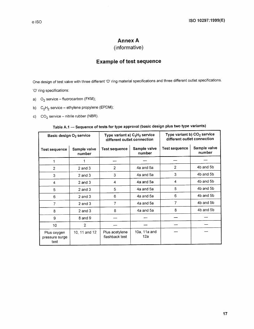
One design of test valve with three different '0' ring material specifications and three different outlet specifications.
'0' ring specifications:
a) O2 service - fluorocarbon (FKM);
b) C2H2 service - ethylene propylene (EPDM);
c) CO2 service - nitrile rubber (NBR).
Table A.1 - Sequence of tests for type approval (basic design plus two type variants)
Basic design O2 service Type variant a) C2H2 service Type variant b) CO2 service different outlet connection different outlet connection
Test sequence Sample valve Test sequence Sample valve Test sequence Sample valve number number number
1 1 - - - -
2 2 and 3 2 4a and 5a 2 4b and 5b
3 2 and 3 3 4a and 5a 3 4b and 5b
4 2 and 3 4 4a and 5a 4 4b and 5b
5 2 and 3 5 4a and 5a 5 4b and 5b
6 2 and 3 6 4a and 5a 6 4b and 5b
7 2 and 3 7 4a and 5a 7 4b and 5b
8 2 and 3 8 4a and 5a 8 4b and 5b
9 8 and 9 - - - -
10 2 - - - -
Plus oxygen 10, 11 and 12 Plus acetylene 10a, 11aand - -pressure surge flashback test 12a
test
17

ISO 10297:1999(E)
Annex B (normative)
Valve impact test
©ISO
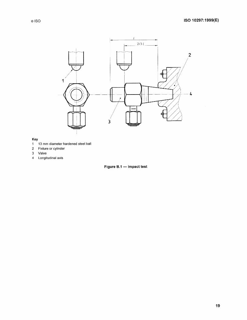
In circumstances where cylinder valves are used in cylinders of water capacity 5 I, or greater, and where valve protection is not intended to be fitted, the following test shall be carried out. The purpose of this test is to ensure that the valve has sufficient inherent strength to withstand impacts which may occur in transit.
One valve, in the closed condition (closed to the torque used in the endurance test, in accordance with 5.4.4) shall be fitted into a gas cylinder neck equipped with the corresponding screw thread or a similar specialized fixture (see Figure B.1), the tightening torque being the same as that as used in service.
The valve shall protrude from the cylinder neck or fixture by the same nominal amount as in service.
The valve shall be struck by a 13 mm diameter hardened steel ball, which has a minimum velocity of 3 mls and an impact energy, as given in Table B.1. The impact shall be at 90 0 to the longitudinal axis of the valve and co-incident with a plane passing through the same axis.
The point of impact shall be two thirds the distance (L) from the plane where the valve stem thread meets the cylinder, to the furthest point of the valve body, measured along the longitudinal axis of the valve (see Figure B.1).
The point of impact on the valve shall not be obscured by features such as outlet connecting threads, bursting disc holders, hand wheels, etc.
The valve shall be struck once only, and shall withstand the appropriate impact energy as given in Table B.1. Distortion due to impact is permissible.
After testing, the valve shall be removed from the test rig, it shall then be fitted into a pressure supply and closed to the previous torque.
Working pressure (Pw) shall be applied to the valve inlet. The leakage shall conform to 4.4.5.
Table B.1 - Impact energy
Cylinder water capacity, -vr Impact energy
I J
5 ~V < 60 200
60 ~v ~150 300
18
©ISO ISO 10297:1999(E)
g;J /~ ,
2
/
1
Key
1 13 mm diameter hardened steel ball
2 Fixture or cylinder 3 Valve
4 Longitudinal axis
Figure B.1 -Impact test
19

ISO 10297:1999(E)
C.1 Test valves
Annex C (normative)
Endurance test
©ISO
Valves to be tested shall be at room temperature (20°C ± 5°C). They shall have been aged in accordance with the procedure specified in Table 1.
C.2 Test medium
The endurance test shall be carried out with dry air or nitrogen filtered to at least 20 11m and at a dew point of less than - 40°C at atmospheric pressure.
NOTE If nitrogen is used the risks of asphyxiation should be considered if a major leak occurs.
Tests shall not be carried out in a waterbath or other liquid medium.
C.3 Test machine
C.3.1 Equipment
Figure C.1 shows a typical arrangement of computer controlled equipment.
C.3.2 Speed and application of torque
The test machine shall be able to open and close the test valves at a speed between 0,167 s-1 and 0,5 s-1(10 rpm and 30 rpm).
At the end of the closing part of the test cycle, overtorque due to dynamic effects shall be no more than 10 % of the set figure.
C.3.3 Alignment
The valve and the machine spindles shall be aligned in such a way that no significant side or axial load is put on the valve during the test.
C.3.4 Calibration
The calibration of the machine shall be verified before commencing and after completion of each endurance test.
20

©ISO ISO 10297: 1999(E)
1 2
a) Closed position
1-
b) Open position
Key 1 DC motor with torque transmitter 6 Adapter 2 Display 7 Input nitrogen, N2 , Pvt
3 Pressure transmitter 8 Outlet 4 Venting valve, closed/open/closed 9 Venting valve, closed 5 Pvt/Pa 10 Pvt
Figure C.1 - Typical arrangement of equipment
21

ISO 10297:1999(E) ©ISO
C.4 Test cycle
C.4.1 Stroke of the endurance test
The test valve shall be cycled through its full stroke minus no more than 45° from the fully open position. This will ensure that the test machine does not apply torque in the fully open position.
C.4.2 Endurance test
This test shall be carried out at an ambient temperature of 20°C ± 5 °C (see Table 1).
The endurance test of 2 000 cycles shall be carried out with the torque specified in 5.4.4 with a tolerance of ± 5 % in the closing direction only. The valve inlet shall be pressurised throughout the whole test to Pvt as defined in 3.3.
The valve outlet shall be connected to a venting device which remains closed during the closing and opening portions of the cycle.
After the valve has reached the closed position, the valve outlet shall be vented down to atmospheric pressure by opening the venting device. Once atmospheric pressure has been reached, the venting device shall be closed and the outlet pressure shall be measured to be no more than 1 % of Pvt immediately before commencing the next cycle.
There shall be a pause of at least 6 s at each fully open and fully closed position of the test valve.
The average time rate shall be no more than 3 cycles per minute and no less than 1 cycle per minute for the duration of the test. Any break longer than 5 min during the duration of the 2 000 cycle test shall be recorded in the test report.
C.4.3 Record
The test cycle shall be recorded e.g. as a graphical illustration, see Figure C.2.
-2~~~~~~~_~b~~!~~~ _____________________________________________________________________ ~ r-- - - ---- - -----
CLosing I CLosed cylinder vaLve 1 Open cylinder val ve 1 1 1 1 1 1
Cyl. valve :6s 1 3 s 16s : Opening i Pause 6 s
Number : Measuring externaL 1 Venting 1 Measuring internal Number Temperature of turns : leakage (spindLe Leakage outlet side leakage (seat Leakage) of turns st abil izationi rest ing
: is measured via outlet : as a drop in pressure) I I
Open 1 I 1 1 1
Venting valve: Closed Closed . 1 1 I
1 1 1 1 1 I I 1 1 1
Pressure outlet Pvl 1 I PV1 I I .. I
Atmospheri~
pressure P~
: 1 I 1
Figure C.2 - Diagram showing a typical cycle for endurance test
22

©ISO ISO 10297:1999{E)
C.S Measurements after the endurance test
The tests specified in Table 1, test sequences 5, 6 and 7 shall be completed. For these tests, the torque used during the endurance test shall not be exceeded.
The test valves shall then be examined in accordance with sequence 8.
23
ISO 10297:1999(E) ©ISO
Bibliography
[1] ISO 11116-2, Gas cylinders - 17E taper thread for connection of valves to gas cylinders - Part 2: Inspection gauges.
[2] ISO 11191, Gas cylinders - 25E taper thread for connection of valves to gas cylinders -Inspection gauges.
24
ISO 10297:1999(E) ©ISO
les 23.020.30; 23.060.40
Price based on 24 pages