Embed Size (px)
Citation preview

By Authority OfTHE UNITED STATES OF AMERICA
Legally Binding Document
By the Authority Vested By Part 5 of the United States Code § 552(a) and Part 1 of the Code of Regulations § 51 the attached document has been duly INCORPORATED BY REFERENCE and shall be considered legally binding upon all citizens and residents of the United States of America. HEED THIS NOTICE: Criminal penalties may apply for noncompliance.
Official Incorporator:THE EXECUTIVE DIRECTOROFFICE OF THE FEDERAL REGISTERWASHINGTON, D.C.
Document Name:
CFR Section(s):
Standards Body:
e


UL 44
ISBN 0-7629-0400-3
Thermoset-Insulated Wires andCables


Underwriters Laboratories Inc. (UL)333 Pfingsten RoadNorthbrook, IL 60062-2096
UL Standard for Safety for Thermoset-Insulated Wires and Cables, UL 44
Fifteenth Edition, Dated March 22, 1999
Revisions: This Standard contains revisions through and including May 13, 2002.
Announcement Bulletin(s): This Standard contains the announcement bulletin(s) dated August 25, 1997and October 30, 1997. The announcement bulletin is located at the end of the Standard (after the adoptionbulletin(s)).
Text that has been changed in any manner is marked with a vertical line in the margin. Changes inrequirements are marked with a vertical line in the margin and are followed by an effective date noteindicating the date of publication or the date on which the changed requirement becomes effective.
The revised requirements are substantially in accordance with UL’s Bulletin(s) on this subject datedDecember 7, 2001. The bulletin(s) is now obsolete and may be discarded.
The revisions dated April 1, 2002 include a reprinted title page (page1) for this Standard.
Pages 70, 71, and 75 were revised on May 13, 2002 to indicate the revision dates of paragraphs 60.12,60.16, 60.17, 60.34, 60.36, and 60.38.
As indicated on the title page (page 1), this UL Standard for Safety is an American National Standard.Attention is directed to the note on the title page of this Standard outlining the procedures to be followedto retain the approved text of this ANSI/UL Standard.
As indicated on the title page (page1), this UL Standard for Safety has been adopted by the Departmentof Defense.
The master for this Standard at UL’s Northbrook Office is the official document insofar as it relates to aUL service and the compliance of a product with respect to the requirements for that product and service,or if there are questions regarding the accuracy of this Standard.
UL’s Standards for Safety are copyrighted by UL. Neither a printed copy of a Standard, nor the distributiondiskette for a Standard-on-Diskette and the file for the Standard on the distribution diskette should bealtered in any way. All of UL’s Standards and all copyrights, ownerships, and rights regarding thoseStandards shall remain the sole and exclusive property of UL.
All rights reserved. No part of this publication may be reproduced, stored in a retrieval system, ortransmitted in any form by any means, electronic, mechanical photocopying, recording, or otherwisewithout prior permission of UL.
Revisions of UL Standards for Safety are issued from time to time. A UL Standard for Safety is currentonly if it incorporates the most recently adopted revisions.
UL provides this Standard ″as is″ without warranty of any kind, either expressed or implied, including butnot limited to, the implied warranties of merchantability or fitness for any purpose.
MAY 13, 2002 − UL 44 tr1

In no event will UL be liable for any special, incidental, consequential, indirect or similar damages,including loss of profits, lost savings, loss of data, or any other damages arising out of the use of or theinability to use this Standard, even if UL or an authorized UL representative has been advised of thepossibility of such damage. In no event shall UL’s liability for any damage ever exceed the price paid forthis Standard, regardless of the form of the claim.
UL will attempt to answer support requests concerning electronic versions of its Standards. However, thissupport service is offered on a reasonable efforts basis only, and UL may not be able to resolve everysupport request. UL supports the electronic versions of its Standards only if they are used under theconditions and operating systems for which it is intended. UL’s support policies may change fromtime-to-time without notification.
UL reserves the right to change the format, presentation, file types and formats, delivery methods andformats, and the like of both its printed and electronic Standards without prior notice.
Purchasers of the electronic versions of UL’s Standards for Safety agree to defend, indemnify, and holdUL harmless from and against any loss, expense, liability, damage, claim, or judgement (includingreasonable attorney’s fees) resulting from any error or deviation introduced while purchaser is storing anelectronic Standard on the purchaser’s computer system.
If a single-user version electronic Standard was purchased, one copy of this Standard may be stored onthe hard disk of a single personal computer, or on a single LAN file-server or the permanent storagedevice of a multiple-user computer in such a manner that this Standard may only be accessed by one userat a time and for which there is no possibility of multiple concurrent access.
If a multiple-user version electronic Standard was purchased, one copy of the Standard may be stored ona single LAN file-server, or on the permanent storage device of a multiple-user computer, or on an Intranetserver. The number of concurrent users shall not exceed the number of users authorized.
Electronic Standards are intended for on-line use, such as for viewing the requirements of a Standard,conducting a word search, and the like. Only one copy of the Standard may be printed from eachsingle-user version of an electronic Standard. Only one copy of the Standard may be printed for eachauthorized user of a multiple-user version of an electronic Standard. Because of differences in thecomputer/software/printer setup used by UL and those of electronic Standards purchasers, the printedcopy obtained by a purchaser may not look exactly like the on-line screen view or the printed Standard.
An employee of an organization purchasing a UL Standard can make a copy of the page or pages beingviewed for their own fair and/or practical internal use.
The requirements in this Standard are now in effect, except for those paragraphs, sections, tables, figures,and/or other elements of the Standard having future effective dates as indicated in the note following theaffected item. The prior text for requirements that have been revised and that have a future effective dateare located after the Standard, and are preceded by a ″SUPERSEDED REQUIREMENTS″ notice.
New product submittals made prior to a specified future effective date will be judged under all of therequirements in this Standard including those requirements with a specified future effective date, unlessthe applicant specifically requests that the product be judged under the current requirements. However, ifthe applicant elects this option, it should be noted that compliance with all the requirements in thisStandard will be required as a condition of continued Listing and Follow-Up Services after the effectivedate, and understanding of this should be signified in writing.
Copyright © 2002 Underwriters Laboratories Inc.
MAY 13, 2002 − UL 44tr2

This Standard consists of pages dated as shown in the following checklist:
Page Date
1-2. . . . . . . . . . . . . . . . . . . . . . . . . . . . . . . . . . . . . . . . . . . . . . . . . . . . . . . . . . . . . . . . . . . . . . . . . . . . . . . April 1, 20023 . . . . . . . . . . . . . . . . . . . . . . . . . . . . . . . . . . . . . . . . . . . . . . . . . . . . . . . . . . . . . . . . . . . . . . . . . . . . . . . . July 13, 20004 . . . . . . . . . . . . . . . . . . . . . . . . . . . . . . . . . . . . . . . . . . . . . . . . . . . . . . . . . . . . . . . . . . . . . . . . . . . . . . . . April 1, 20025. . . . . . . . . . . . . . . . . . . . . . . . . . . . . . . . . . . . . . . . . . . . . . . . . . . . . . . . . . . . . . . . . . . . . . . . . . . . . . . . May 18, 20006 . . . . . . . . . . . . . . . . . . . . . . . . . . . . . . . . . . . . . . . . . . . . . . . . . . . . . . . . . . . . . . . . . . . . . . . . . . . . . . . . April 1, 20027. . . . . . . . . . . . . . . . . . . . . . . . . . . . . . . . . . . . . . . . . . . . . . . . . . . . . . . . . . . . . . . . . . . . . . . . . . . . . . . . May 18, 20008 . . . . . . . . . . . . . . . . . . . . . . . . . . . . . . . . . . . . . . . . . . . . . . . . . . . . . . . . . . . . . . . . . . . . . . . . . . . November 1, 20018A . . . . . . . . . . . . . . . . . . . . . . . . . . . . . . . . . . . . . . . . . . . . . . . . . . . . . . . . . . . . . . . . . . . . . . . . . . . . . . . April 1, 20028B-9. . . . . . . . . . . . . . . . . . . . . . . . . . . . . . . . . . . . . . . . . . . . . . . . . . . . . . . . . . . . . . . . . . . . . . . . . . . . . July 13, 200010. . . . . . . . . . . . . . . . . . . . . . . . . . . . . . . . . . . . . . . . . . . . . . . . . . . . . . . . . . . . . . . . . . . . . . . . . . . . . March 22, 199911 . . . . . . . . . . . . . . . . . . . . . . . . . . . . . . . . . . . . . . . . . . . . . . . . . . . . . . . . . . . . . . . . . . . . . . . . . . . . . . . April 1, 200212-13 . . . . . . . . . . . . . . . . . . . . . . . . . . . . . . . . . . . . . . . . . . . . . . . . . . . . . . . . . . . . . . . . . . . . . . . . . . . . July 13, 200014 . . . . . . . . . . . . . . . . . . . . . . . . . . . . . . . . . . . . . . . . . . . . . . . . . . . . . . . . . . . . . . . . . . . . . . . . . . . . . . . April 1, 200215. . . . . . . . . . . . . . . . . . . . . . . . . . . . . . . . . . . . . . . . . . . . . . . . . . . . . . . . . . . . . . . . . . . . . . . . . . . . . . . July 13, 200016-18 . . . . . . . . . . . . . . . . . . . . . . . . . . . . . . . . . . . . . . . . . . . . . . . . . . . . . . . . . . . . . . . . . . . . . . . . . . . . April 1, 200219 . . . . . . . . . . . . . . . . . . . . . . . . . . . . . . . . . . . . . . . . . . . . . . . . . . . . . . . . . . . . . . . . . . . . . . . . . . November 1, 200120-21 . . . . . . . . . . . . . . . . . . . . . . . . . . . . . . . . . . . . . . . . . . . . . . . . . . . . . . . . . . . . . . . . . . . . . . . . . . . . April 1, 200222-22B . . . . . . . . . . . . . . . . . . . . . . . . . . . . . . . . . . . . . . . . . . . . . . . . . . . . . . . . . . . . . . . . . . . . . . . . . . July 13, 200023. . . . . . . . . . . . . . . . . . . . . . . . . . . . . . . . . . . . . . . . . . . . . . . . . . . . . . . . . . . . . . . . . . . . . . . . . . . . . March 22, 199924-27 . . . . . . . . . . . . . . . . . . . . . . . . . . . . . . . . . . . . . . . . . . . . . . . . . . . . . . . . . . . . . . . . . . . . . . . . . . . . April 1, 200228-31 . . . . . . . . . . . . . . . . . . . . . . . . . . . . . . . . . . . . . . . . . . . . . . . . . . . . . . . . . . . . . . . . . . . . . . . . . . March 22, 199932-34B . . . . . . . . . . . . . . . . . . . . . . . . . . . . . . . . . . . . . . . . . . . . . . . . . . . . . . . . . . . . . . . . . . . . . . . . . . May 18, 200035. . . . . . . . . . . . . . . . . . . . . . . . . . . . . . . . . . . . . . . . . . . . . . . . . . . . . . . . . . . . . . . . . . . . . . . . . . . . . March 22, 199936-36B . . . . . . . . . . . . . . . . . . . . . . . . . . . . . . . . . . . . . . . . . . . . . . . . . . . . . . . . . . . . . . . . . . . . . . . . . . . April 1, 200237-38 . . . . . . . . . . . . . . . . . . . . . . . . . . . . . . . . . . . . . . . . . . . . . . . . . . . . . . . . . . . . . . . . . . . . . . . . . . March 22, 199939 . . . . . . . . . . . . . . . . . . . . . . . . . . . . . . . . . . . . . . . . . . . . . . . . . . . . . . . . . . . . . . . . . . . . . . . . . . . . . . . April 1, 200240. . . . . . . . . . . . . . . . . . . . . . . . . . . . . . . . . . . . . . . . . . . . . . . . . . . . . . . . . . . . . . . . . . . . . . . . . . . . . . . July 13, 200041. . . . . . . . . . . . . . . . . . . . . . . . . . . . . . . . . . . . . . . . . . . . . . . . . . . . . . . . . . . . . . . . . . . . . . . . . . . . . March 22, 199942-43 . . . . . . . . . . . . . . . . . . . . . . . . . . . . . . . . . . . . . . . . . . . . . . . . . . . . . . . . . . . . . . . . . . . . . . . . . . . . April 1, 200244. . . . . . . . . . . . . . . . . . . . . . . . . . . . . . . . . . . . . . . . . . . . . . . . . . . . . . . . . . . . . . . . . . . . . . . . . . . . . March 22, 199945 . . . . . . . . . . . . . . . . . . . . . . . . . . . . . . . . . . . . . . . . . . . . . . . . . . . . . . . . . . . . . . . . . . . . . . . . . . . . . . . April 1, 200246-47 . . . . . . . . . . . . . . . . . . . . . . . . . . . . . . . . . . . . . . . . . . . . . . . . . . . . . . . . . . . . . . . . . . . . . . . . . . . . July 13, 200048-50D . . . . . . . . . . . . . . . . . . . . . . . . . . . . . . . . . . . . . . . . . . . . . . . . . . . . . . . . . . . . . . . . . . . . . . . . . . . April 1, 200251. . . . . . . . . . . . . . . . . . . . . . . . . . . . . . . . . . . . . . . . . . . . . . . . . . . . . . . . . . . . . . . . . . . . . . . . . . . . . . . July 13, 200052 . . . . . . . . . . . . . . . . . . . . . . . . . . . . . . . . . . . . . . . . . . . . . . . . . . . . . . . . . . . . . . . . . . . . . . . . . . . . . . May 18, 200053-57 . . . . . . . . . . . . . . . . . . . . . . . . . . . . . . . . . . . . . . . . . . . . . . . . . . . . . . . . . . . . . . . . . . . . . . . . . . March 22, 199958-59 . . . . . . . . . . . . . . . . . . . . . . . . . . . . . . . . . . . . . . . . . . . . . . . . . . . . . . . . . . . . . . . . . . . . . . . . . . . . July 13, 200060. . . . . . . . . . . . . . . . . . . . . . . . . . . . . . . . . . . . . . . . . . . . . . . . . . . . . . . . . . . . . . . . . . . . . . . . . . . . . March 22, 199961 . . . . . . . . . . . . . . . . . . . . . . . . . . . . . . . . . . . . . . . . . . . . . . . . . . . . . . . . . . . . . . . . . . . . . . . . . . . . . . . April 1, 200262-63 . . . . . . . . . . . . . . . . . . . . . . . . . . . . . . . . . . . . . . . . . . . . . . . . . . . . . . . . . . . . . . . . . . . . . . . . . . March 22, 199964-68 . . . . . . . . . . . . . . . . . . . . . . . . . . . . . . . . . . . . . . . . . . . . . . . . . . . . . . . . . . . . . . . . . . . . . . . . . . . . April 1, 200269. . . . . . . . . . . . . . . . . . . . . . . . . . . . . . . . . . . . . . . . . . . . . . . . . . . . . . . . . . . . . . . . . . . . . . . . . . . . . March 22, 199970-71. . . . . . . . . . . . . . . . . . . . . . . . . . . . . . . . . . . . . . . . . . . . . . . . . . . . . . . . . . . . . . . . . . . . . . . . . . . . May 13, 200272-74 . . . . . . . . . . . . . . . . . . . . . . . . . . . . . . . . . . . . . . . . . . . . . . . . . . . . . . . . . . . . . . . . . . . . . . . . . . . . April 1, 200275 . . . . . . . . . . . . . . . . . . . . . . . . . . . . . . . . . . . . . . . . . . . . . . . . . . . . . . . . . . . . . . . . . . . . . . . . . . . . . . May 13, 200276-78 . . . . . . . . . . . . . . . . . . . . . . . . . . . . . . . . . . . . . . . . . . . . . . . . . . . . . . . . . . . . . . . . . . . . . . . . . . . . April 1, 2002
MAY 13, 2002 − UL 44 tr3

MAY 13, 2002 − UL 44tr4
No Text on This Page

MARCH 22, 1999(Title Page Reprinted: April 1, 2002)
1
UL 44
Standard for Thermoset-Insulated Wires and Cables
The First through Fifth editions were titled Rubber-Covered Wires and Cables.The Sixth through Thirteenth editions were titled Rubber-Insulated Wires andCables.
First Edition – November, 1917Second Edition – March, 1932
Third Edition – March, 1939Fourth Edition – June, 1940
Fifth Edition – April, 1956Sixth Edition – May, 1961
Seventh Edition – July, 1968Eighth Edition – June, 1975
Ninth Edition – December, 1976Tenth Edition – December, 1977
Eleventh Edition – February, 1983Twelfth Edition – August, 1983
Thirteenth Edition – October, 1991Fourteenth Edition – January, 1997
Fifteenth Edition
March 22, 1999
UL maintains this standard under the ANSI continuous maintenance procedure,resulting in each revision being designated as ANSI approved upon completionof the process. The Fifteenth Edition of UL 44, including revisions publishedthrough April 1, 2002, was designated as the American National StandardANSI/UL 44 on March 1, 2002.
An effective date included as a note immediately following certain requirementsis one established by Underwriters Laboratories Inc.
Approved as ANSI/UL 44 – 2002, March 1, 2002
The Department of Defense (DoD) has adopted UL 44 on April 5, 1985. Thepublication of revised pages or a new edition of this Standard will not invalidatethe DoD adoption.
Comments on this standard should be made in writing to the UL-MelvilleStandards Department at 1285 Walt Whitman Road, Melville, New York11747–3081.
ANSI/UL 44 – 2002
Revisions of this Standard will be made by issuing revised or additional pagesbearing their date of issue. A UL Standard is current only if it incorporates themost recently adopted revisions, all of which are itemized on the transmittal noticethat accompanies the latest set of revised requirements.
ISBN 0-7629-0400-3
COPYRIGHT © 1975, 2002 UNDERWRITERS LABORATORIES INC.

CONTENTS
FOREWORD . . . . . . . . . . . . . . . . . . . . . . . . . . . . . . . . . . . . . . . . . . . . . . . . . . . . . . . . . . . . . . . . . . . . . . . . . . . . . . . .8
INTRODUCTION
1 Scope . . . . . . . . . . . . . . . . . . . . . . . . . . . . . . . . . . . . . . . . . . . . . . . . . . . . . . . . . . . . . . . . . . . . . . . . . . . . . .8A2 Units of Measurement . . . . . . . . . . . . . . . . . . . . . . . . . . . . . . . . . . . . . . . . . . . . . . . . . . . . . . . . . . . . . . . .8A3 References . . . . . . . . . . . . . . . . . . . . . . . . . . . . . . . . . . . . . . . . . . . . . . . . . . . . . . . . . . . . . . . . . . . . . . . . .8B4 Materials . . . . . . . . . . . . . . . . . . . . . . . . . . . . . . . . . . . . . . . . . . . . . . . . . . . . . . . . . . . . . . . . . . . . . . . . . . .8B5 Index Table . . . . . . . . . . . . . . . . . . . . . . . . . . . . . . . . . . . . . . . . . . . . . . . . . . . . . . . . . . . . . . . . . . . . . . . . .8B
CONDUCTOR(S)
6 Metal . . . . . . . . . . . . . . . . . . . . . . . . . . . . . . . . . . . . . . . . . . . . . . . . . . . . . . . . . . . . . . . . . . . . . . . . . . . . . . .167 Size, Temper, and Assembly . . . . . . . . . . . . . . . . . . . . . . . . . . . . . . . . . . . . . . . . . . . . . . . . . . . . . . . . . .168 Conductor Diameter and Cross-Sectional Area . . . . . . . . . . . . . . . . . . . . . . . . . . . . . . . . . . . . . . . . . .189 Metal Coating . . . . . . . . . . . . . . . . . . . . . . . . . . . . . . . . . . . . . . . . . . . . . . . . . . . . . . . . . . . . . . . . . . . . . . .1810 Joints . . . . . . . . . . . . . . . . . . . . . . . . . . . . . . . . . . . . . . . . . . . . . . . . . . . . . . . . . . . . . . . . . . . . . . . . . . . . .1811 Resistance . . . . . . . . . . . . . . . . . . . . . . . . . . . . . . . . . . . . . . . . . . . . . . . . . . . . . . . . . . . . . . . . . . . . . . . . .1912 Stranding . . . . . . . . . . . . . . . . . . . . . . . . . . . . . . . . . . . . . . . . . . . . . . . . . . . . . . . . . . . . . . . . . . . . . . . . . .1913 Separator . . . . . . . . . . . . . . . . . . . . . . . . . . . . . . . . . . . . . . . . . . . . . . . . . . . . . . . . . . . . . . . . . . . . . . . . . .22
INSULATION
14 Material and Application . . . . . . . . . . . . . . . . . . . . . . . . . . . . . . . . . . . . . . . . . . . . . . . . . . . . . . . . . . . . .2215 Thicknesses of Insulation . . . . . . . . . . . . . . . . . . . . . . . . . . . . . . . . . . . . . . . . . . . . . . . . . . . . . . . . . . .22A
15.1 General . . . . . . . . . . . . . . . . . . . . . . . . . . . . . . . . . . . . . . . . . . . . . . . . . . . . . . . . . . . . . . . . . . . .22A16 Centering . . . . . . . . . . . . . . . . . . . . . . . . . . . . . . . . . . . . . . . . . . . . . . . . . . . . . . . . . . . . . . . . . . . . . . . . . .26
NONMETALLIC COVERINGS AND FILLERS
17 General . . . . . . . . . . . . . . . . . . . . . . . . . . . . . . . . . . . . . . . . . . . . . . . . . . . . . . . . . . . . . . . . . . . . . . . . . . . .2618 Number of Coverings . . . . . . . . . . . . . . . . . . . . . . . . . . . . . . . . . . . . . . . . . . . . . . . . . . . . . . . . . . . . . . . .2719 Fillers . . . . . . . . . . . . . . . . . . . . . . . . . . . . . . . . . . . . . . . . . . . . . . . . . . . . . . . . . . . . . . . . . . . . . . . . . . . . .2720 Tapes . . . . . . . . . . . . . . . . . . . . . . . . . . . . . . . . . . . . . . . . . . . . . . . . . . . . . . . . . . . . . . . . . . . . . . . . . . . . .2721 Cotton Braids . . . . . . . . . . . . . . . . . . . . . . . . . . . . . . . . . . . . . . . . . . . . . . . . . . . . . . . . . . . . . . . . . . . . . .28
21.1 General . . . . . . . . . . . . . . . . . . . . . . . . . . . . . . . . . . . . . . . . . . . . . . . . . . . . . . . . . . . . . . . . . . . . .2821.2 Coverage . . . . . . . . . . . . . . . . . . . . . . . . . . . . . . . . . . . . . . . . . . . . . . . . . . . . . . . . . . . . . . . . . . .28
22 All-Glass and Glass/Cotton Braids . . . . . . . . . . . . . . . . . . . . . . . . . . . . . . . . . . . . . . . . . . . . . . . . . . . .3423 Cotton Wraps and Servings . . . . . . . . . . . . . . . . . . . . . . . . . . . . . . . . . . . . . . . . . . . . . . . . . . . . . . . . . .35
23.1 General . . . . . . . . . . . . . . . . . . . . . . . . . . . . . . . . . . . . . . . . . . . . . . . . . . . . . . . . . . . . . . . . . . . . .3523.2 Coverage . . . . . . . . . . . . . . . . . . . . . . . . . . . . . . . . . . . . . . . . . . . . . . . . . . . . . . . . . . . . . . . . . . .36
24 Glass Wraps . . . . . . . . . . . . . . . . . . . . . . . . . . . . . . . . . . . . . . . . . . . . . . . . . . . . . . . . . . . . . . . . . . . . . . .3825 Spun-Rayon Braids and Wraps . . . . . . . . . . . . . . . . . . . . . . . . . . . . . . . . . . . . . . . . . . . . . . . . . . . . . . .3826 Saturation of Fibrous Coverings Other Than Tapes . . . . . . . . . . . . . . . . . . . . . . . . . . . . . . . . . . . . .3827 Finish . . . . . . . . . . . . . . . . . . . . . . . . . . . . . . . . . . . . . . . . . . . . . . . . . . . . . . . . . . . . . . . . . . . . . . . . . . . . .3828 Thicknesses of Jacket . . . . . . . . . . . . . . . . . . . . . . . . . . . . . . . . . . . . . . . . . . . . . . . . . . . . . . . . . . . . . . .3929 Lubrication . . . . . . . . . . . . . . . . . . . . . . . . . . . . . . . . . . . . . . . . . . . . . . . . . . . . . . . . . . . . . . . . . . . . . . . . .40
JULY 13, 2000 THERMOSET-INSULATED WIRES AND CABLES - UL 44 3

METAL COVERINGS
30 General . . . . . . . . . . . . . . . . . . . . . . . . . . . . . . . . . . . . . . . . . . . . . . . . . . . . . . . . . . . . . . . . . . . . . . . . . . . .4131 Lead Sheath . . . . . . . . . . . . . . . . . . . . . . . . . . . . . . . . . . . . . . . . . . . . . . . . . . . . . . . . . . . . . . . . . . . . . . .4132 Aluminum Sheath . . . . . . . . . . . . . . . . . . . . . . . . . . . . . . . . . . . . . . . . . . . . . . . . . . . . . . . . . . . . . . . . . . .41
LAY OF CABLED CONDUCTORS
33 General . . . . . . . . . . . . . . . . . . . . . . . . . . . . . . . . . . . . . . . . . . . . . . . . . . . . . . . . . . . . . . . . . . . . . . . . . . . .41
ASSEMBLIES THAT INCLUDE SINGLE-CONDUCTOR THERMOSET-INSULATED WIRES
34 General . . . . . . . . . . . . . . . . . . . . . . . . . . . . . . . . . . . . . . . . . . . . . . . . . . . . . . . . . . . . . . . . . . . . . . . . . . . .42
CABLE FOR DEEP-WELL SUBMERSIBLE WATER PUMPS
35 General . . . . . . . . . . . . . . . . . . . . . . . . . . . . . . . . . . . . . . . . . . . . . . . . . . . . . . . . . . . . . . . . . . . . . . . . . . . .42
PERFORMANCE
DIELECTRIC VOLTAGE-WITHSTAND TEST IN WATER
36 General . . . . . . . . . . . . . . . . . . . . . . . . . . . . . . . . . . . . . . . . . . . . . . . . . . . . . . . . . . . . . . . . . . . . . . . . . . . .45
TEST FOR INSULATION RESISTANCE AT 60.0°F (15.6°C)
37 General . . . . . . . . . . . . . . . . . . . . . . . . . . . . . . . . . . . . . . . . . . . . . . . . . . . . . . . . . . . . . . . . . . . . . . . . . . . .4638 Temperature Factor . . . . . . . . . . . . . . . . . . . . . . . . . . . . . . . . . . . . . . . . . . . . . . . . . . . . . . . . . . . . . . .50C
TEST FOR INSULATION RESISTANCE IN WATER AT RATED TEMPERATURE
39 General . . . . . . . . . . . . . . . . . . . . . . . . . . . . . . . . . . . . . . . . . . . . . . . . . . . . . . . . . . . . . . . . . . . . . . . . . . . .5339.1 Minimum value . . . . . . . . . . . . . . . . . . . . . . . . . . . . . . . . . . . . . . . . . . . . . . . . . . . . . . . . . . . . . . .5339.2 Maximum rate of decrease . . . . . . . . . . . . . . . . . . . . . . . . . . . . . . . . . . . . . . . . . . . . . . . . . . . .5639.3 Test method . . . . . . . . . . . . . . . . . . . . . . . . . . . . . . . . . . . . . . . . . . . . . . . . . . . . . . . . . . . . . . . . .56
TEST FOR INSULATION RESISTANCE IN AIR AT 97.0°C (206.6°F)
40 General . . . . . . . . . . . . . . . . . . . . . . . . . . . . . . . . . . . . . . . . . . . . . . . . . . . . . . . . . . . . . . . . . . . . . . . . . . . .5740.1 Minimum value . . . . . . . . . . . . . . . . . . . . . . . . . . . . . . . . . . . . . . . . . . . . . . . . . . . . . . . . . . . . . . .5740.2 Maximum rate of decrease . . . . . . . . . . . . . . . . . . . . . . . . . . . . . . . . . . . . . . . . . . . . . . . . . . . .6040.3 Test method . . . . . . . . . . . . . . . . . . . . . . . . . . . . . . . . . . . . . . . . . . . . . . . . . . . . . . . . . . . . . . . . .60
ALTERNATIVE SPARK TESTING
41 General . . . . . . . . . . . . . . . . . . . . . . . . . . . . . . . . . . . . . . . . . . . . . . . . . . . . . . . . . . . . . . . . . . . . . . . . . . . .61
CAPACITANCE AND RELATIVE-PERMITTIVITY TESTS
42 General . . . . . . . . . . . . . . . . . . . . . . . . . . . . . . . . . . . . . . . . . . . . . . . . . . . . . . . . . . . . . . . . . . . . . . . . . . . .62
APRIL 1, 2002THERMOSET-INSULATED WIRES AND CABLES - UL 444

TEST FOR STABILITY FACTOR
43 General . . . . . . . . . . . . . . . . . . . . . . . . . . . . . . . . . . . . . . . . . . . . . . . . . . . . . . . . . . . . . . . . . . . . . . . . . . . .62
TEST FOR GLASS CONTENT OF BRAID ON TYPE SA WIRE
44 General . . . . . . . . . . . . . . . . . . . . . . . . . . . . . . . . . . . . . . . . . . . . . . . . . . . . . . . . . . . . . . . . . . . . . . . . . . . .63
TEST FOR FALLING PARTICLES AND DRIPPING FROM FIBROUS-COVERED WIRE AND CABLE
45 General . . . . . . . . . . . . . . . . . . . . . . . . . . . . . . . . . . . . . . . . . . . . . . . . . . . . . . . . . . . . . . . . . . . . . . . . . . . .63
TEST FOR MOISTURE ABSORPTION BY FIBROUS COVERINGS OTHER THAN TAPE
46 General . . . . . . . . . . . . . . . . . . . . . . . . . . . . . . . . . . . . . . . . . . . . . . . . . . . . . . . . . . . . . . . . . . . . . . . . . . . .63
COLD-BEND TEST
47 General . . . . . . . . . . . . . . . . . . . . . . . . . . . . . . . . . . . . . . . . . . . . . . . . . . . . . . . . . . . . . . . . . . . . . . . . . . . .63
COLD-IMPACT TEST
48 General . . . . . . . . . . . . . . . . . . . . . . . . . . . . . . . . . . . . . . . . . . . . . . . . . . . . . . . . . . . . . . . . . . . . . . . . . . . .64
DEFORMATION TEST
49 General . . . . . . . . . . . . . . . . . . . . . . . . . . . . . . . . . . . . . . . . . . . . . . . . . . . . . . . . . . . . . . . . . . . . . . . . . . . .64
CRUSHING TEST (TYPES XHHW-2, XHHW, AND XHH)
50 General . . . . . . . . . . . . . . . . . . . . . . . . . . . . . . . . . . . . . . . . . . . . . . . . . . . . . . . . . . . . . . . . . . . . . . . . . . . .65
TEST FOR DIELECTRIC BREAKDOWN AFTER GLANCING IMPACT (TYPES XHHW-2, XHHW, ANDXHH)
51 General . . . . . . . . . . . . . . . . . . . . . . . . . . . . . . . . . . . . . . . . . . . . . . . . . . . . . . . . . . . . . . . . . . . . . . . . . . . .65
TEST FOR DIELECTRIC BREAKDOWN AFTER SCORING (TYPES XHHW-2, XHHW, AND XHH)
52 General . . . . . . . . . . . . . . . . . . . . . . . . . . . . . . . . . . . . . . . . . . . . . . . . . . . . . . . . . . . . . . . . . . . . . . . . . . . .65
HORIZONTAL-SPECIMEN FLAME TEST
53 General . . . . . . . . . . . . . . . . . . . . . . . . . . . . . . . . . . . . . . . . . . . . . . . . . . . . . . . . . . . . . . . . . . . . . . . . . . . .66
VW-1 (VERTICAL-SPECIMEN) FLAME TEST
54 General . . . . . . . . . . . . . . . . . . . . . . . . . . . . . . . . . . . . . . . . . . . . . . . . . . . . . . . . . . . . . . . . . . . . . . . . . . . .66
VERTICAL-TRAY FLAME TEST
55 General . . . . . . . . . . . . . . . . . . . . . . . . . . . . . . . . . . . . . . . . . . . . . . . . . . . . . . . . . . . . . . . . . . . . . . . . . . . .66
MAY 18, 2000 THERMOSET-INSULATED WIRES AND CABLES - UL 44 5

SUNLIGHT-RESISTANCE TEST
56 General . . . . . . . . . . . . . . . . . . . . . . . . . . . . . . . . . . . . . . . . . . . . . . . . . . . . . . . . . . . . . . . . . . . . . . . . . . . .67
LIMITED SMOKE
57 General . . . . . . . . . . . . . . . . . . . . . . . . . . . . . . . . . . . . . . . . . . . . . . . . . . . . . . . . . . . . . . . . . . . . . . . . . . . .68
TESTS FOR OIL-RESISTANCE
58 General . . . . . . . . . . . . . . . . . . . . . . . . . . . . . . . . . . . . . . . . . . . . . . . . . . . . . . . . . . . . . . . . . . . . . . . . . . . .68
TESTS FOR GASOLINE- AND OIL-RESISTANCE
59 General . . . . . . . . . . . . . . . . . . . . . . . . . . . . . . . . . . . . . . . . . . . . . . . . . . . . . . . . . . . . . . . . . . . . . . . . . . . .68
MARKINGS
60 Details . . . . . . . . . . . . . . . . . . . . . . . . . . . . . . . . . . . . . . . . . . . . . . . . . . . . . . . . . . . . . . . . . . . . . . . . . . . . .69
APRIL 1, 2002THERMOSET-INSULATED WIRES AND CABLES - UL 446

MAY 18, 2000 THERMOSET-INSULATED WIRES AND CABLES - UL 44 7
No Text on This Page

FOREWORD
A. This Standard contains basic requirements for products covered by Underwriters Laboratories Inc. (UL)under its Follow-Up Service for this category within the limitations given below and in the Scope sectionof this Standard. These requirements are based upon sound engineering principles, research, records oftests and field experience, and an appreciation of the problems of manufacture, installation, and usederived from consultation with and information obtained from manufacturers, users, inspection authorities,and others having specialized experience. They are subject to revision as further experience andinvestigation may show is necessary or desirable.
B. The observance of the requirements of this Standard by a manufacturer is one of the conditions of thecontinued coverage of the manufacturer’s product.
C. A product which complies with the text of this Standard will not necessarily be judged to comply withthe Standard if, when examined and tested, it is found to have other features which impair the level ofsafety contemplated by these requirements.
D. A product that contains features, characteristics, components, materials, or systems new or differentfrom those covered by the requirements in this standard, and that involves a risk of fire or of electric shockor injury to persons shall be evaluated using appropriate additional component and end-productrequirements to maintain the level of safety as originally anticipated by the intent of this standard. Aproduct whose features, characteristics, components, materials, or systems conflict with specificrequirements or provisions of this standard does not comply with this standard. Revision of requirementsshall be proposed and adopted in conformance with the methods employed for development, revision, andimplementation of this standard.
E. UL, in performing its functions in accordance with its objectives, does not assume or undertake todischarge any responsibility of the manufacturer or any other party. The opinions and findings of ULrepresent its professional judgment given with due consideration to the necessary limitations of practicaloperation and state of the art at the time the Standard is processed. UL shall not be responsible to anyonefor the use of or reliance upon this Standard by anyone. UL shall not incur any obligation or liability fordamages, including consequential damages, arising out of or in connection with the use, interpretation of,or reliance upon this Standard.
F. Many tests required by the Standards of UL are inherently hazardous and adequate safeguards forpersonnel and property shall be employed in conducting such tests.
NOVEMBER 1, 2001THERMOSET-INSULATED WIRES AND CABLES - UL 448

INTRODUCTION
1 Scope
1.1 These requirements cover 14 – 4/0 AWG and 213 – 2000 kcmil sizes of Type XHHW-2, XHHW, XHH,RHW-2, RHH, RHW, SIS, and SA wires and cables for use in accordance with Article 310 and otherapplicable parts of National Electrical Code. Deep-well pump cables and other multiple-conductorassemblies to which a type-letter designation is not assigned are included in these requirements.
1.1 revised April 1, 2002
1.2 These requirements do not cover wires or cables for use at potentials higher than 2000 V.
1.3 Although these requirements cover parallel and cabled assemblies of two or more insulatedconductors, they do not cover complete armored (AC series), metal-clad (Type MC), medium-voltage(Type MV), or service-entrance (Types SE and USE) cables. These cables are covered in separaterequirements.
1.4 Deleted November 1, 2001
2 Units of Measurement
2.1 In addition to being stated in the inch/pound units that are customary in the USA, each numericalrequirement in this standard is also stated in units that make the requirement conveniently usable incountries employing the various metric systems (practical SI and customary). Equivalent – although notexactly identical – results are to be expected from applying a requirement in USA or metric terms.Equipment calibrated in metric units is to be used when a requirement is applied in metric terms.
2.1 revised April 1, 2002
APRIL 1, 2002 THERMOSET-INSULATED WIRES AND CABLES - UL 44 8A

3 References
3.1 Wherever the designation ″UL 1581″ is used in this wire standard, reference is to be made to thedesignated part(s) of the Reference Standard for Electrical Wires, Cables, and Flexible Cords (UL 1581).
4 Materials
4.1 Each material used in a thermoset-insulated wire or cable shall be compatible with all of the othermaterials in the wire or cable.
5 Index Table
5.1 A thermoset-insulated wire or cable shall be as specified in Table 5.1 or 5.2 and shall comply in allrespects with the requirements for the construction details and test performance that are applicable to thatconstruction.
JULY 13, 2000THERMOSET-INSULATED WIRES AND CABLES - UL 448B

JULY 13, 2000 THERMOSET-INSULATED WIRES AND CABLES - UL 44 9
No Text on This Page

5.2 The table serves as an index to the requirements for construction details and test performance. Eachvertical column serves as an index to the requirements that apply to the particular wire or cable whosetype letters appear at the top of the column. The figures in parentheses are the numbers of the paragraphsin the text of this Standard, to which reference is to be made. References in square brackets are to UL1581.
MARCH 22, 1999THERMOSET-INSULATED WIRES AND CABLES - UL 4410

Tab
le5.
1In
dex
tore
quire
men
tsa
for
XH
HW
-2,
XH
HW
,X
HH
,R
HH
,R
HW
-2,
and
RH
WT
able
5.1
revi
sed
Apr
il1,
2002
Typ
e-le
tter
desi
gnat
ion
XH
HW
-2X
HH
WX
HH
RH
HR
HW
-2R
HW
Max
imum
Tem
pera
ture
90°C
(194
°F)
wet
ordr
y
75°C
(167
°F)
wet
90°C
(194
°F)
dry
90°C
(194
°F)
dry
90°C
(194
°F)
dry
90°C
(194
°F)
wet
ordr
y75
°C(1
67°F
)w
etor
dry
Max
imum
Vol
tage
600
600
or20
00
Con
duct
orS
ize
14A
WG
–20
00kc
mil
(Tab
le7.
1)
Num
ber
ofC
ondu
ctor
sO
ne,
2pa
ralle
l,2
orm
ore
cabl
ed
Con
duct
orM
etal
14an
d13
AW
G–
soft-
anne
aled
copp
er,
12A
WG
–20
00kc
mil
–al
umin
um,
copp
er-c
lad
alum
inum
,or
soft-
anne
aled
copp
er(6
.1)
Con
duct
orD
imen
sion
sS
ee8.
1–
8.3
for
diam
eter
and
cros
s-se
ctio
nala
rea
Con
duct
or–
Gen
eral
Met
alco
atin
g(9
.1an
d9.
2)S
plic
es(1
0.1
and
10.2
)S
epar
ator
(13.
1an
d13
.2)
Con
duct
orR
esis
tanc
e(1
1.1)
Con
duct
orS
tran
ding
(12.
1–
12.7
)
Insu
latio
nM
ater
ial(s
)bX
LE
PC
V
SB
R/II
R/N
RC
PC
PE
EP
CV
EP
XL
Sili
cone
rubb
er(R
HH
only
)
Insu
latio
n–
Gen
eral
App
licat
ion
(14.
1),
Join
ts(1
4.2)
,O
ther
mat
eria
ls(1
4.3)
,C
ente
ring
(16.
1)
Thi
ckne
ssof
Insu
latio
n–
Ave
rage
(15.
1)
Thi
ckne
ssof
Insu
latio
n–
Min
imum
atA
nyP
oint
(15.
1)
APRIL 1, 2002 THERMOSET-INSULATED WIRES AND CABLES - UL 44 11
Tabl
e5.
1C
ontin
ued
onN
ext
Pag
e

Tab
le5.
1C
ontin
ued
Typ
e-le
tter
desi
gnat
ion
XH
HW
-2X
HH
WX
HH
RH
HR
HW
-2R
HW
Non
met
allic
Cov
erin
gsan
dF
iller
s(1
7.1
and
17.2
)
Gen
eral
(17.
1an
d17
.2)
Num
ber
ofC
over
ings
(18.
1–
18.4
)F
iller
s(1
9.1)
Tap
es(2
0.1
–20
.4)
Cot
ton
Bra
ids
(21.
1–
21.2
.7)
All-
Gla
ssan
dG
lass
/Cot
ton
Bra
ids
(22.
1–
22.4
)A
ram
idB
raid
(22.
5)C
otto
nW
raps
and
Ser
ving
s(2
3.1.
1–
23.2
.4)
Gla
ssW
raps
(24.
1an
d24
.2)
Spu
n-R
ayon
Bra
ids
and
Wra
ps(2
5.1)
Sat
urat
ion
ofF
ibro
usC
over
ings
(26.
1–26
.4)
Fin
ish
(27.
1)C
PC
PE
Neo
pren
e(R
HW
,R
HH
,R
HW
-2)
NB
R/P
VC
(RH
,R
HW
)T
hick
ness
ofJa
cket
(28.
1)Lu
bric
atio
n(2
9.1)
Lay
ofC
able
dC
ondu
ctor
s(3
3.1)
Ass
embl
ies
Tha
tIn
clud
eS
ingl
e-C
ondu
ctor
The
rmos
et-
Insu
late
dW
ires
(34.
1)
Pum
pC
able
Gen
eral
(1.1
,19
.1,
29.1
,33
.1,
35.1
,60
.6,
60.7
,an
d60
.32)
none
(1.1
,19
.1,
29.1
,33
.1,
35.1
,60
.6,
60.7
,an
d60
.32)
Thi
ckne
ssof
Jack
et(3
5.1)
none
(35.
1)
Phy
sica
lPro
pert
ies
ofJa
cket
(35.
1)no
ne(3
5.1)
Phy
sica
lPro
pert
ies
ofIn
sula
tionb
Una
ged
XL
EP
CV
SB
R/II
R/N
RC
PC
PE
EP
CV
EP
XL
Sili
cone
rubb
er(R
HH
only
)
Afte
rA
ging
Phy
sica
lPro
pert
ies
ofJa
cket
bU
nage
dno
ne
CP
CP
EN
eopr
ene
NB
R/P
VC
Afte
rA
ging
Die
lect
ricV
olta
ge-W
ithst
and
(36.
1–
36.3
)
Insu
latio
nR
esis
tanc
eat
60.0
°F(1
5.6°
C)
(37.
1an
d38
.1)
Insu
latio
nR
esis
tanc
ein
Wat
erat
Rat
edT
empe
ratu
re(3
9.1.
1–
39.3
.1)
none
(39.
1.1–
39.3
.1)
Insu
latio
nR
esis
tanc
ein
Air
at97
.0°C
(206
.6°F
)no
ne(4
0.1.
1–
40.3
.2)
none
Alte
rnat
ive
Spa
rkT
estin
g(4
1.1)
Con
tinui
ty[p
ars.
900.
13–
900.
17of
UL
1581
]
JULY 13, 2000THERMOSET-INSULATED WIRES AND CABLES - UL 4412
Tabl
e5.
1C
ontin
ued
onN
ext
Pag
e

Tab
le5.
1C
ontin
ued
Typ
e-le
tter
desi
gnat
ion
XH
HW
-2X
HH
WX
HH
RH
HR
HW
-2R
HW
Cap
acita
nce
and
Rel
ativ
eP
erm
ittiv
ity(4
2.1)
none
(42.
1)
Sta
bilit
yF
acto
r(4
3.1)
none
(43.
1)
Gla
ssC
onte
ntno
ne(2
2.1)
Fal
ling
Par
ticle
san
dD
rippi
ngfr
omF
ibro
usC
over
ings
none
(45.
1)
Moi
stur
eA
bsor
ptio
nby
Fib
rous
Cov
erin
gsO
ther
Tha
nT
ape
none
(46.
1)
Col
dB
end
(47.
1)
Col
dIm
pact
(48.
1)
Def
orm
atio
n(4
9.1)
Cru
shin
g(5
0.1
and
50.2
)no
ne
Gla
ncin
gIm
pact
(51.
1)no
ne
Sco
ring
(52.
1)no
ne
Hor
izon
talF
lam
e(5
3.1)
VW
-1F
lam
e(5
4.1)
Ver
tical
-Tra
yF
lam
eS
ingl
e-an
dm
ultip
le-c
ondu
ctor
(55.
1–
55.4
)
Tra
yC
able
sS
unlig
htR
esis
tanc
eS
ingl
e-an
dja
cket
edm
ultip
le-c
ondu
ctor
(56.
1–
56.4
)
Sun
light
Res
ista
nce
for
Mes
seng
erU
se
Sin
gle-
and
jack
eted
mul
tiple
-co
nduc
tor
(56.
1–56
.4)
Mes
seng
erus
eno
tap
plic
able
Sin
gle-
and
jack
eted
mul
tiple
-co
nduc
tor
(56.
1–
56.4
)
Mes
seng
erus
eno
tap
plic
able
Sin
gle-
and
jack
eted
mul
tiple
-co
nduc
tor
(56.
1–
56.4
)
Mes
seng
erus
eno
tap
plic
able
Oil
Res
ista
nce
(57.
1an
d57
.2)
Gas
olin
e-an
dO
il-R
esis
tanc
e(5
8.1)
Mar
king
s(6
0.1–
60.4
4)a
See
5.2.
bT
heph
ysic
alpr
oper
ties
requ
irem
ents
for
indi
vidu
alm
ater
iala
rein
UL
1581
.S
ee47
.1in
UL
1581
.S
eeal
so40
.2in
UL
1581
.
JULY 13, 2000 THERMOSET-INSULATED WIRES AND CABLES - UL 44 13

Tab
le5.
2In
dex
tore
quire
men
tsa
for
Typ
esS
Aan
dS
IST
able
5.2
revi
sed
Apr
il1,
2002
Typ
e-le
tter
desi
gnat
ion
SA
SIS
Max
imum
Tem
pera
ture
90°C
(194
°F)
dry
90°C
(194
°F)
dry
200°
C(3
92°F
)sp
ecia
ldry
Max
imum
Vol
tage
600
Con
duct
orS
ize
14A
WG
–20
00kc
mil
(6.1
,8.
1)14
–4/
0A
WG
(6.1
,8.
1)
Num
ber
ofC
ondu
ctor
sO
ne,
2pa
ralle
l,2
orm
ore
cabl
ed
Con
duct
orM
etal
Sof
t-an
neal
edco
pper
14,
13A
WG
soft-
anne
aled
copp
er,
12–
4/0
AW
G–
alum
inum
,co
pper
-cla
dal
umin
um,
orso
ft-an
neal
edco
pper
(6.1
)
Con
duct
orD
imen
sion
sS
ee8.
1–8.
3fo
rdi
amet
eran
dcr
oss-
sect
iona
lare
a
Con
duct
or–
Gen
eral
Met
alco
atin
g(9
.1an
d9.
2)S
plic
es(1
0.1
and
10.2
)S
epar
ator
(13.
1an
d13
.2)
Con
duct
orR
esis
tanc
e(1
1.1)
Con
duct
orS
tran
ding
(12.
1–
12.7
)
Insu
latio
nM
ater
ial(s
)b20
0°C
silic
one
CP
CP
EE
PC
VX
L
Insu
latio
n–
Gen
eral
App
licat
ion
(14.
1)Jo
ints
(14.
2)O
ther
mat
eria
l(14
.3)
Cen
terin
g(1
6.1)
Thi
ckne
ssof
Insu
latio
n–A
vera
ge(1
5.1)
Thi
ckne
ssof
Insu
latio
n–
Min
imum
atA
nyP
oint
(15.
1)
Non
met
allic
Cov
erin
gsan
dF
iller
s
Gen
eral
(17.
1an
d17
.2)
Num
ber
ofC
over
ings
(18.
1–18
.4)
Fill
ers
(19.
1)T
apes
(20.
1–
20.4
)G
lass
Bra
ids
(22.
1–
22.4
)A
ram
idB
raid
s(2
2.5)
Sat
urat
ion
ofF
ibro
usC
over
ings
(26.
1–26
.4)
Fin
ish
(27.
1)Lu
bric
atio
n(2
9.1)
none
Lay
ofC
able
dC
ondu
ctor
s(3
3.1)
Ass
embl
ies
Tha
tIn
clud
eS
ingl
e-C
ondu
ctor
Rub
ber-
Insu
late
dW
ires
(34.
1)
Phy
sica
lPro
pert
ies
ofIn
sula
tionb
Una
ged
200°
Csi
licon
eE
PC
V,
XL
CP
,C
PE
Afte
rA
ging
APRIL 1, 2002THERMOSET-INSULATED WIRES AND CABLES - UL 4414
Tabl
e5.
2C
ontin
ued
onN
ext
Pag
e

Tab
le5.
2C
ontin
ued
Typ
e-le
tter
desi
gnat
ion
SA
SIS
Die
lect
ricV
olta
ge-W
ithst
and
(36.
1–
36.3
)
Insu
latio
nR
esis
tanc
eat
60.0
°F(1
5.6°
C)
(37.
1an
d38
.1)
Alte
rnat
ive
Spa
rkT
estin
g(4
1.1)
Con
tinui
ty[p
ars.
900.
13–
900.
17of
UL
1581
]
Gla
ssC
onte
nt(4
4.1)
none
Col
dB
end
(47.
1)
Col
dIm
pact
(48.
1)
Def
orm
atio
nno
ne(4
9.1)
Hor
izon
talF
lam
eT
est
(53.
1)
VW
-1F
lam
eT
est
(54.
1)
Ver
tical
-Tra
yF
lam
eT
est
(55.
1–
55.4
)
Mar
king
s(6
0.1
–60
.41)
a See
5.2.
b The
phys
ical
prop
ertie
sre
quire
men
tsfo
rin
divi
dual
mat
eria
lare
inU
L15
81.
See
47.1
ofU
L15
81.
See
also
40.2
ofU
L15
81.
JULY 13, 2000 THERMOSET-INSULATED WIRES AND CABLES - UL 44 15

CONDUCTOR(S)
6 Metal
6.1 Only soft-annealed copper, copper-clad aluminum, or an aluminum alloy shall be used for theconductor or conductors in a wire or cable. Soft-annealed copper shall comply with ASTM B 3-01. Each27 – 36 AWG (14.2 – 5.0 mils or 0.361 – 0.127 mm) strand in wire rated for 200°C (392°F) shall beprotected against oxidation by a coating of nickel complying with ASTM B 355-95, a coating of silvercomplying with ASTM B 298-99, or a coating of another metal or alloy (evaluation required – lead, tin/lead,and tin coatings are not acceptable). Uncoated or tin/lead-coated or tin-coated solid conductors anduncoated or tin/lead-coated or tin-coated strands whose diameter is at least 0.015 inch or 0.38 mm areacceptable in wire rated for 200°C (392°F). Solid aluminum conductors in size 12 – 8 AWG shall complywith the requirements for aluminum-wire stock (aluminum-alloy conductor material). All other aluminumconductors shall comply with the requirements for semi-annealed 8000 series aluminum conductors inRequirements for Aluminum Conductors of an 8000 Series Alloy, Section 10 of UL 1581. Copper-cladaluminum conductors shall comply with the requirements in Requirements for Copper-Clad AluminumConductors, Section 11 of UL 1581.
6.1 revised April 1, 2002
7 Size, Temper, and Assembly
7.1 Conductors shall be of the size, temper, and assembly indicated for the finished wire type in Table7.1.
APRIL 1, 2002THERMOSET-INSULATED WIRES AND CABLES - UL 4416

Tab
le7.
1C
ondu
ctor
sT
able
7.1
revi
sed
Apr
il1,
2002
Typ
esof
wire
Siz
esan
dm
etal
(See
Tab
les
5.1
and
5.2)
Tem
per
Ass
embl
y
XH
HW
-2,
XH
HW
,X
HH
,R
HH
,R
HW
,R
HW
-2,
SIS
a ,S
A
14–
4/0
AW
Gco
pper
Sof
t-an
neal
edS
olid
2–
4/0
AW
Gco
pper
Sof
t-an
neal
edC
ompa
ctst
rand
ing
b,f
14A
WG
–20
00kc
mil
copp
erS
oft-
anne
aled
Com
pres
sed
stra
ndin
gan
dev
ery
othe
rty
peof
stra
ndin
gbco
vere
din
Tab
le21
0.1
ofU
L15
81ot
her
than
com
pact
stra
ndin
g
XH
HW
-2,
XH
HW
,X
HH
,R
HW
-2,
RH
H,
RH
W,
SIS
a
12–
8A
WG
alum
inum
cS
olid
6–
4/0
AW
Gal
umin
umS
emi-a
nnea
ledd
Sol
id
12A
WG
–20
00kc
mil
alum
inum
Sem
i-ann
eale
ddC
ompr
esse
dst
rand
ing
and
ever
yot
her
type
ofst
rand
ingb
cove
red
inT
able
210.
2of
UL
1581
othe
rth
anco
mpa
ctst
rand
ing
12A
WG
–10
00kc
mil
alum
inum
Sem
i-ann
eale
ddC
ompa
ctst
rand
ingb
12–
4/0
AW
Gco
pper
-cla
dal
umin
umd
Sol
id
12A
WG
–20
00kc
mil
copp
er-c
lad
alum
inum
dA
nyty
peof
stra
ndin
gbco
vere
din
Tab
le21
0.2
ofU
L15
81ot
her
than
com
pact
and
com
pres
sed
stra
ndin
ga
Typ
eS
ISis
limite
dto
14–
4/0
AW
Gco
pper
and
12–
4/0
AW
Gal
umin
uman
dco
pper
-cla
dal
umin
um.
bS
ee12
.1–
12.7
.c
Alu
min
um-w
irest
ock
(alu
min
um-a
lloy
cond
ucto
rm
ater
ial).
dS
ee6.
1.e
Del
eted
.fS
ee60
.39.
APRIL 1, 2002 THERMOSET-INSULATED WIRES AND CABLES - UL 44 17

8 Conductor Diameter and Cross-Sectional Area
8.1 The nominal, maximum (1.01 x nominal), and minimum (0.98 x nominal) diameters of solid andstranded conductors are shown in Tables 20.1, 20.2, 20.3, 20.3.1, 20.4, 20.5, and 20.6 of UL 1581.Conductor diameter is to be measured using the method shown in Conductor Diameter, Section 200 ofUL 1581.
8.1 revised March 22, 1999
8.2 Compressed unilay copper conductors that are smaller in diameter than the requirement (0.98 xnominal as indicated in Table 20.3 of UL 1581) for compressed concentric-lay conductors shall be markedthe same as compact conductors in accordance with 60.39.
8.3 The nominal cross-sectional area of a conductor is indicated in Table 20.1 of UL 1581 (not arequirement).
9 Metal Coating
9.1 Where the insulation adjacent to a copper or copper-clad aluminum conductor is of a material thatcorrodes unprotected copper in the test in Conductor Corrosion, Section 500 of UL 1581, and where aprotective separator is not provided, the solid conductor and each of the individual strands of a strandedconductor shall be separately covered with a coating of tin complying with ASTM B 33-00, of a tin/leadalloy complying with ASTM B 189-95, of nickel complying with ASTM B 355-95, of silver complying withASTM B 298-99, or of another metal or alloy (evaluation required).
9.1 revised April 1, 2002
9.2 The use of a metal coating, when not required for corrosion protection, is still appropriate for use onsolid or individual wires (strands) or selected wires, such as the outer layer of wires of a strandedconductor. The metal coating when used shall comply with 9.1
9.2 revised March 22, 1999
10 Joints
10.1 A joint in a solid conductor or in one of the individual wires of a stranded conductor shall be madein a workmanlike manner and shall not change the diameter of the solid conductor, the individual wirestrand, or the overall stranded conductor. A joint shall not be made in a stranded conductor as a whole.A joint in a stranded conductor shall be made by separately joining each individual wire. A joint shall bemade only before any coverings are applied to an insulated conductor and before a conductor isassembled into a cable. The insulation applied to such joints shall be equivalent to that removed and shallcomply with the requirements in this Standard. A joint in a compact- or compressed-stranded conductorshall be made before compacting or compressing.
10.1 revised March 22, 1999
10.2 In a rope-lay-stranded conductor, which consists of a central core surrounded by one or more layersof stranded members (primary groups), splices of the members as individual units shall not be closertogether than two lay lengths.
10.2 revised March 22, 1999
APRIL 1, 2002THERMOSET-INSULATED WIRES AND CABLES - UL 4418

11 Resistance
11.1 The direct-current resistance of any length of conductor in ohms per thousand conductor feet or inohms per conductor kilometer shall not be higher than the maximum (nominal x 1.02) resistance indicatedin the applicable table in D-C Conductor Resistance, Section 30 of UL 1581 at 20°C (68°F) or at 25°C(77°F) when measured as described in D-C Conductor Resistance, Section 220 of UL 1581. The d-cresistance of each conductor in a finished Type XHHW-2M, XHHWM, XHHM, RHW-2M, RHHM, RHWM,RHM, SISM, or SAM cable shall not exceed the value tabulated in the applicable one of the tables inSection 30 of UL 1581 for a single conductor multiplied by whichever of the following factors is applicable:
Construction Multiplier
Cabled in one layer 1.02
Cabled in more than one layer 1.03
Cabled as one pair 1.04
Cabled as an assembly of pairs or other precabled units. 1.04
11.1 revised March 22, 1999
12 Stranding
12.1 A stranded conductor shall have the number of strands indicated in Table 12.1.
Table 12.1Conductor stranding
Table 12.1 revised November 1, 2001
Size of wireNumber of strands incombination unilay
Minimum number of strands b
Compact stranded All others
AWG
14, 13 19a – 7
12 – 9 19a 7 7
8 19a 7 7
7 – 2 19 7 7
1 – 4/0 19 18 19
kcmil
213 – 500 – 35 37
501 – 1000 – 58 61
1001 – 1500 – – 91
1501 – 2000 – – 127
a Copper only.b Conductors with a lesser number of strands shall be permitted based on the results of an investigation which shall includetesting for connectability and bending.
12.2 The individual wires used in making up a stranded conductor are usually drawn to the samediameter which is not required to be the diameter of any AWG or other standard gauge number.
12.2 revised March 22, 1999
NOVEMBER 1, 2001 THERMOSET-INSULATED WIRES AND CABLES - UL 44 19

12.3 Copper strands smaller than 36 AWG and aluminum and copper-clad aluminum strands smallerthan 22 AWG shall not be used.
12.3 revised April 1, 2002
12.4 A 19-wire combination round-wire unilay-stranded conductor of soft-annealed copper, or analuminum alloy as indicated in 6.1, shall be round and shall consist of a straight central wire, an inner layerof six wires of the same diameter as the central wire with the six wires having identical lengths of lay andan outer layer consisting of six wires of the same diameter as the central wire alternated with six smallerwires having a diameter of 0.732 times the diameter of the central wire and with all twelve wires of theouter layer having the same length of lay and direction of lay as the six wires of the inner layer. Noparticular assembly of the individual wires of any other stranded conductor is required. However, simplebunching (untwisted strands) shall not be used for the entire conductor or any part thereof. The length oflay of the strands in a single-bunch bunch-stranded conductor shall not be greater than indicated in Table12.2. The direction of lay of the strands in a single-bunch bunch-stranded conductor shall be left- hand.Any type of stranding in Table 210.2 of UL 1581 other than compact stranding or single-bunchbunch-stranding shall comply with 12.6 or 12.7 as applicable. The direction of lay of the outer layer shallbe left-hand in all cases.
Table 12.2Length of lay of strands in a single-bunch bunch-stranded conductor a
Table 12.2 revised May 14, 2001
AWG size of conductor
Maximum length of lay
inches mm
14 AWG 1-5/8 41
13 1-5/8 41
12 2 51
11 2 51
10 2-1/2 64
9 2-1/2 64
8 2-3/4 70
7 3 76
6 3-3/8 86
5 AWG – 2000 kcmil 16 times the diameter of the conductor
a Includes the constructions in note a to Table 210.2 of UL 1581.
12.5 A compact-stranded conductor shall be a round conductor consisting of a central core (one or morestrands) surrounded by one or more layers of helically laid strands. A compact-stranded copper conductorshall consist of uncoated strands. A compact-stranded aluminum conductor shall have all layers with thesame direction of lay (left-hand unidirectional). A compact-stranded copper conductor is to be left- handunidirectional or have the direction of lay reversed in adjacent layers (concentric-lay-stranded with theouter layer left-handed) and with each layer rolled, drawn, or otherwise compressively formed to changethe originally round or partially preshaped strands to various close-fitting shapes that achieve almostcomplete filling of the spaces originally present between the strands. Each layer shall be compactedbefore the next layer is applied, and each compacted layer – including the outermost layer – shall havea smooth, round outer surface. The length of lay of the strands in the outer layer of a 1 AWG – 1000 kcmilconductor shall be 8 – 16 times the overall diameter of that layer. The length of lay of the strands in theouter layer of a 12 – 2 AWG conductor shall be 8.0 – 17.5 times the overall diameter of that layer. Acompact-stranded conductor shall not be segmented.
12.5 revised November 1, 2001
APRIL 1, 2002THERMOSET-INSULATED WIRES AND CABLES - UL 4420

12.6 A compressed-stranded conductor shall be a round conductor consisting of a central core (one ormore strands) surrounded by one or more layers of helically laid strands with either the direction of layreversed in successive layers, or of unilay or unidirectional lay. The direction of lay of the outer layer shallbe left-hand in all cases. The strands of one or more layers may be compressed by rolling, drawing, orother means to change the originally round strands to various shapes that achieve filling of some of thespaces originally present between the strands.
12.6 revised November 1, 2001
12.7 Every stranded conductor covered in Table 210.2 of UL 1581 other than a compact-strandedconductor or a single-bunch bunch-stranded conductor shall comply with the following:
a) The direction of lay of the strands, members, or ropes in a 6 AWG – 2000 kcmil conductorother than a combination unilay or compressed unilay or compressed unidirectional layconductor shall be reversed in successive layers. Rope-bunched lay and rope-concentric layconductors shall be either unidirectional or reversed. All unidirectional lays and the outer layerof reversed lays shall be in the left-hand direction.
b) For a bunch-stranded member of a rope-lay-stranded conductor in which the members areformed into rope-stranded components that are then cabled into the final conductor, the lengthof lay of the individual members within each component shall not be more than 30 times theoutside diameter of one of those members.
c) For a concentric-stranded member of a rope-lay-stranded conductor, the length of lay of theindividual strands in a member shall be 8 – 16 times the outside diameter of the member. Thedirection of lay of the strands in each member shall be reversed in successive layers of themember.
d) The length of lay of the strands in both layers of a 19-wire combination round-wire unilay-stranded copper or aluminum conductor shall be 8 – 16 times the outside diameter of thecompleted conductor. Otherwise, the length of lay of the strands in every layer of a concentric-lay-stranded or compressed stranded conductor consisting of fewer than 37 strands shall be 8 –16 times the outside diameter of the conductor.
e) The length of lay of the strands in the outer two layers of a concentric-lay-stranded orcompressed stranded conductor consisting of 37 or more strands shall be 8 – 16 times theoutside diameter of the conductor.
f) The length of lay of the members or ropes in the outer layer of a rope-lay-strandedconductor shall be 8 – 16 times the outside diameter of that layer.
12.7 revised April 1, 2002
APRIL 1, 2002 THERMOSET-INSULATED WIRES AND CABLES - UL 44 21

13 Separator
13.1 The insulation shall be kept by the manufacturing process or a separator from penetrating betweenthe strands of a conductor (see Insulation Fall-In Test, Section 520 of UL 1581). A separator is notrequired between the conductor and the insulation of a solid or stranded wire or cable. When used aseparator shall be electrically nonconductive (an insulation grade is not required) and shall not be countedas part of the required insulation.
13.1 revised March 22, 1999
13.2 A separator used between a conductor and insulation shall be colored or shall be opaque to makethe separator clearly distinguishable from the conductor once the insulation is removed. The color shallbe other than copper, silver, green or green and yellow and shall be solid, striped, or in some otherpattern.
13.2 revised March 22, 1999
INSULATION
14 Material and Application
14.1 A single-conductor wire or cable and each conductor of a multiple-conductor cable shall be insulatedfor its entire length with one of the insulations specified for the construction in Table 5.1 or 5.2. Theinsulation shall be applied directly to the surface of the conductor or to any separator and shall cover theconductor or any separator completely. The insulation shall fit tightly to the conductor and shall notadhere. For the case of an insulated conductor for use in a pump cable, see tag marking required in60.34(g). The insulation shall not have any defects visible with normal or corrected vision withoutmagnification.
14.1 revised March 22, 1999
14.2 Any repair or joint in the insulation shall be made in a workmanlike manner resulting in all partsaffected in the process complying with the same electrical tests as the remainder of the insulation. Thethickness of insulation at the repaired part or joint shall comply with the requirements in 15.1.1.
14.3 Either of the following materials that the manufacturer wishes to use as an insulation or a jacket shallbe evaluated for the requested temperature rating as described in Long-Term Aging, Section 481 of UL1581:
a) Material generically different from any insulation or jacket material that is named in Table 5.1or 5.2 for the construction (new material).
b) Material that is named in Table 5.1 or 5.2 yet does not comply with the short-term testsspecified for the material in Specific Materials, Section 50 of UL 1581.
The temperature rating of materials (a) and (b) shall be as required for the specific thermoset-insulatedwire or cable type. The thickness of insulation and/or jacket using materials (a) and/or (b) shall be asrequired for the specific type. Investigation of the electrical, mechanical, and physical characteristics of thewire or cable using material (a) and/or (b) shall show the material(s) to be comparable in performance toan insulation or jacket material named in Table 5.1 or 5.2 for the required temperature rating. Theinvestigation shall include tests such as crushing, impact, abrasion, deformation, heat shock, insulationresistance, and dielectric voltage-withstand, or other tests as appropriate.
14.3 revised July 13, 2000
JULY 13, 2000THERMOSET-INSULATED WIRES AND CABLES - UL 4422
15 Thicknesses of Insulation
15.1 General
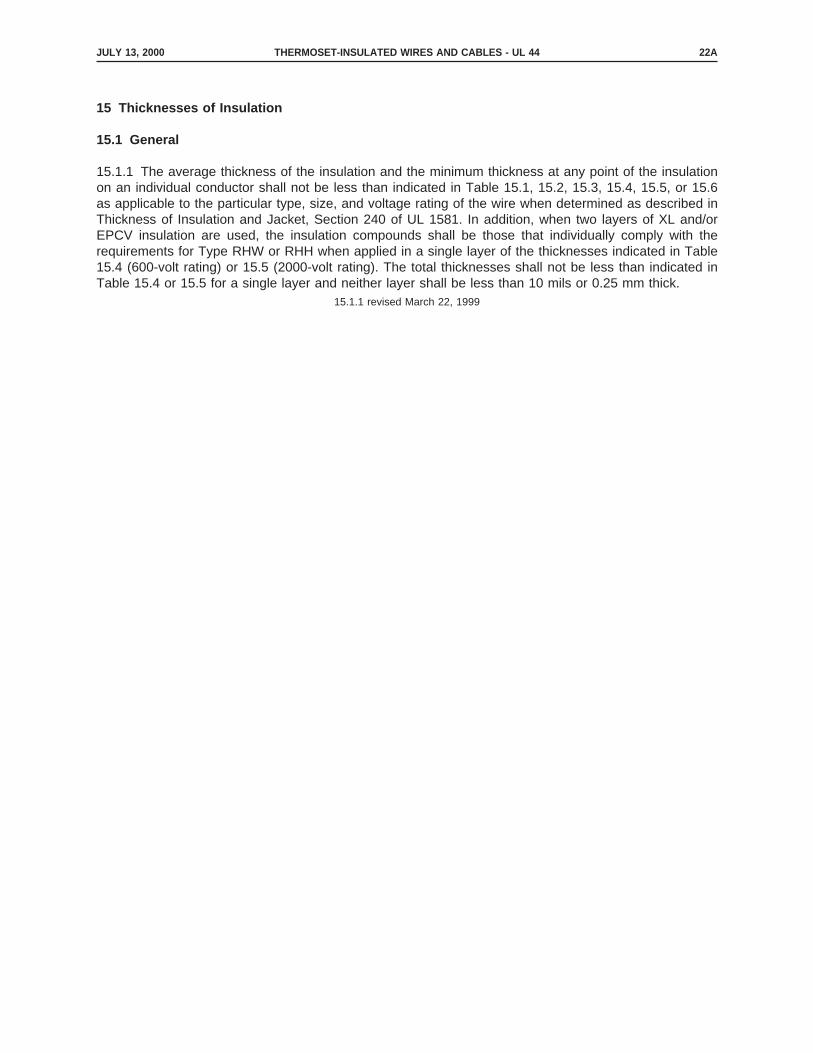
15.1.1 The average thickness of the insulation and the minimum thickness at any point of the insulationon an individual conductor shall not be less than indicated in Table 15.1, 15.2, 15.3, 15.4, 15.5, or 15.6as applicable to the particular type, size, and voltage rating of the wire when determined as described inThickness of Insulation and Jacket, Section 240 of UL 1581. In addition, when two layers of XL and/orEPCV insulation are used, the insulation compounds shall be those that individually comply with therequirements for Type RHW or RHH when applied in a single layer of the thicknesses indicated in Table15.4 (600-volt rating) or 15.5 (2000-volt rating). The total thicknesses shall not be less than indicated inTable 15.4 or 15.5 for a single layer and neither layer shall be less than 10 mils or 0.25 mm thick.
15.1.1 revised March 22, 1999
JULY 13, 2000 THERMOSET-INSULATED WIRES AND CABLES - UL 44 22A

JULY 13, 2000THERMOSET-INSULATED WIRES AND CABLES - UL 4422B
No Text on This Page
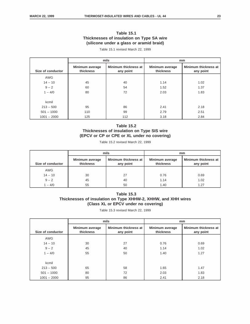
Table 15.1Thicknesses of insulation on Type SA wire
(silicone under a glass or aramid braid)
Table 15.1 revised March 22, 1999
Size of conductor
mils mm
Minimum averagethickness
Minimum thickness atany point
Minimum averagethickness
Minimum thickness atany point
AWG
14 – 10 45 40 1.14 1.02
9 – 2 60 54 1.52 1.37
1 – 4/0 80 72 2.03 1.83
kcmil
213 – 500 95 86 2.41 2.18
501 – 1000 110 99 2.79 2.51
1001 – 2000 125 112 3.18 2.84
Table 15.2Thicknesses of insulation on Type SIS wire
(EPCV or CP or CPE or XL under no covering)
Table 15.2 revised March 22, 1999
Size of conductor
mils mm
Minimum averagethickness
Minimum thickness atany point
Minimum averagethickness
Minimum thickness atany point
AWG
14 – 10 30 27 0.76 0.69
9 – 2 45 40 1.14 1.02
1 – 4/0 55 50 1.40 1.27
Table 15.3Thicknesses of insulation on Type XHHW-2, XHHW, and XHH wires
(Class XL or EPCV under no covering)
Table 15.3 revised March 22, 1999
Size of conductor
mils mm
Minimum averagethickness
Minimum thickness atany point
Minimum averagethickness
Minimum thickness atany point
AWG
14 – 10 30 27 0.76 0.69
9 – 2 45 40 1.14 1.02
1 – 4/0 55 50 1.40 1.27
kcmil
213 – 500 65 58 1.65 1.47
501 – 1000 80 72 2.03 1.83
1001 – 2000 95 86 2.41 2.18
MARCH 22, 1999 THERMOSET-INSULATED WIRES AND CABLES - UL 44 23

Tab
le15
.4T
hick
ness
esof
insu
latio
non
600-
VT
ype
RH
W-2
,R
HH
,an
dR
HW
wire
sT
able
15.4
revi
sed
Apr
il1,
2002
Siz
eof
cond
ucto
r
Wire
with
insu
latio
nco
nsis
ting
ofC
lass
SB
R/II
R/N
Run
der
ane
opre
ne,
NB
R/P
VC
,C
PE
orC
Pja
cket
ora
fibro
usco
verin
gan
dw
irew
ithin
sula
tion
cons
istin
gof
silic
one
rubb
er(R
HH
only
)or
EP
unde
ra
neop
rene
,N
BR
/PV
C,
CP
E,
orC
Pja
cket
ora
fibro
usco
verin
gan
dw
irew
ithin
sula
tion
cons
istin
gof
Cla
ssC
P,
CP
E,
orX
Lor
EP
CV
unde
rno
cove
ring
Wire
with
com
posi
tein
sula
tion
cons
istin
gof
ala
yer
ofC
P,
CP
E,
EP
CV
,or
XL
over
ala
yer
ofE
Pw
ithou
tan
you
ter
cove
ring
Inne
rLa
yer
–E
PO
uter
Laye
r–
CP
,C
PE
,E
PC
V,
orX
L
Min
imum
thic
knes
sM
inim
umth
ickn
ess
Min
imum
thic
knes
s
mils
mm
mils
mm
mils
mm
Ave
rage
At
any
poin
tA
vera
geA
tan
ypo
int
Ave
rage
At
any
poin
ta
Ave
rage
At
any
poin
ta
Ave
rage
At
any
poin
ta
Ave
rage
At
any
poin
ta
AB
AB
AB
AB
AW
G
14–
1045
401.
141.
0230
2728
0.76
0.69
0.71
1514
120.
380.
360.
30
9,8,
760
541.
521.
3745
4042
1.14
1.02
1.07
1514
120.
380.
360.
30
6–
260
541.
521.
3745
4044
1.14
1.02
1.12
3027
240.
760.
690.
61
1–
4/0
8072
2.03
1.83
5550
541.
401.
271.
3745
4036
1.14
1.02
0.91
kcm
il
213
–50
095
862.
412.
1865
5865
1.65
1.47
1.65
6558
521.
651.
471.
32
501
–10
0011
099
2.79
2.51
8072
782.
031.
831.
9865
5852
1.65
1.47
1.32
1001
–20
0012
511
23.
182.
84–
––
––
––
––
––
–
aT
hem
inim
umth
ickn
ess
atan
ypo
int
shal
lnot
bele
ssth
anin
dica
ted
inco
lum
nA
orB
unde
rIn
ner
Laye
rw
ithth
em
inim
umth
ickn
ess
atan
ypo
int
not
less
than
indi
cate
din
the
corr
espo
ndin
gco
lum
nA
orB
unde
rO
utle
rLa
yer.
The
thic
knes
sin
colu
mn
Bun
der
Inne
rLa
yer
plus
the
thic
knes
sin
Col
umn
Bun
der
Out
ler
Laye
req
uals
90pe
rcen
tof
the
sum
ofth
eav
erag
eth
ickn
esse
sin
dica
ted
unde
rIn
ner
Laye
ran
dO
utle
rLa
yer.
APRIL 1, 2002THERMOSET-INSULATED WIRES AND CABLES - UL 4424

Tab
le15
.5T
hick
ness
esof
insu
latio
non
2000
-VT
ype
RH
W-2
,R
HH
,an
dR
HW
wire
sT
able
15.5
revi
sed
Apr
il1,
2002
Siz
eof
cond
ucto
r
Wire
with
insu
latio
nco
nsis
ting
ofsi
licon
eru
bber
(RH
Hon
ly)
orE
Pun
der
ane
opre
ne,
NB
R/
PV
C,
CP
E,
orC
Pja
cket
ora
fibro
usco
verin
gan
dw
irew
ithin
sula
tion
cons
istin
gof
Cla
ssX
Lor
EP
CV
unde
rno
cove
ring
Wire
with
insu
latio
nco
nsis
ting
ofC
Por
CP
Eun
der
noco
verin
gan
dw
irew
ithin
sula
tion
cons
istin
gof
Cla
ssS
BR
/IIR
/NR
unde
ra
neop
rene
,N
BR
/PV
C,
CP
E,
orC
Pja
cket
ora
fibro
usco
verin
g
Wire
with
com
posi
tein
sula
tion
cons
istin
gof
ala
yer
ofC
P,
CP
E,
EP
CV
,or
XL
over
ala
yer
ofE
Pw
ithou
tan
you
ter
cove
ring
Inne
rLa
yer
–E
PO
uter
Laye
r–
CP
,C
PE
,E
PC
V,
orX
L
Min
imum
thic
knes
sM
inim
umth
ickn
ess
Min
imum
thic
knes
s
mils
mm
mils
mm
mils
mm
mils
mm
Avg
.A
tan
ypo
int
Avg
.A
tan
ypo
int
Avg
.A
tan
ypo
int
Avg
.A
tan
ypo
int
Avg
.A
tan
ypo
int
aA
vg.
At
any
poin
taA
vg.
At
any
poin
taA
vg.
At
any
poin
ta
AB
AB
AB
AB
AW
G
14–
1060
541.
521.
3780
722.
031.
8345
4042
1.14
1.02
1.07
1514
120.
380.
360.
30
970
631.
781.
6080
722.
031.
8355
5051
1.40
1.27
1.30
1514
120.
380.
360.
30
8,7
7063
1.78
1.60
8072
2.03
1.83
5550
521.
401.
271.
3230
2724
0.76
0.69
0.61
6–
270
631.
781.
6095
862.
412.
1855
5052
1.40
1.27
1.32
3027
240.
760.
690.
61
1–
4/0
9081
2.29
2.06
110
992.
792.
5165
5863
1.65
1.47
1.60
4540
361.
141.
020.
91
kcm
il
213
–50
010
594
2.67
2.39
125
112
3.18
2.84
7568
741.
901.
731.
8865
5852
1.65
1.47
1.32
501
–10
0012
010
83.
052.
7414
012
63.
563.
2090
8188
2.29
2.06
2.24
6558
521.
651.
471.
32
1001
–20
0014
012
63.
563.
2014
012
63.
563.
2011
510
411
32.
922.
642.
8795
8576
2.41
2.16
1.93
aT
hem
inim
umth
ickn
ess
atan
ypo
int
shal
lnot
bele
ssth
anin
dica
ted
inC
olum
nA
orB
unde
rIn
ner
Laye
rw
ithth
em
inim
umth
ickn
ess
atan
ypo
int
not
less
than
indi
cate
din
the
corr
espo
ndin
gC
olum
nA
orB
unde
rO
uter
Laye
r.T
heth
ickn
ess
inC
olum
nB
unde
rE
Ppl
usth
eth
ickn
ess
inC
olum
nB
unde
rO
uter
Laye
req
uals
90pe
rcen
tof
the
sum
ofth
eav
erag
eth
ickn
esse
sin
dica
ted
unde
rIn
ner
Laye
ran
dO
uter
Laye
r.
APRIL 1, 2002 THERMOSET-INSULATED WIRES AND CABLES - UL 44 25

Table 15.6Thicknesses of insulation on Type RH wire
Table 15.6 deleted July 13, 2000
16 Centering
16.1 The insulation shall have a circular cross section, shall be applied concentrically about the conductoror any separator (making the conductor plus any separator well centered in the insulation), and shall fittightly on the conductor or any separator. When the insulation is applied in more than one layer, adjacentlayers shall be vulcanized, cured, or cross-linked into an integral mass and this mass shall be taken as awhole for all measurements and tests with the exception that the thicknesses of the layers of compositeinsulation shall be measured separately.
NONMETALLIC COVERINGS AND FILLERS
17 General
17.1 A single-conductor wire or cable, and each conductor of any 2-conductor flat parallel wire or cableand of any cabled multiple-conductor cable, shall have a covering of fibrous material or a jacket appliedover the outer surface of the insulation unless it is indicated in note a to the physical-properties table inUL 1581 (see Table 50.1, 50.62, and 50.231 of UL 1581) that a covering is not required over theinsulation. A covering other than the tape, braid, wrap, neoprene jacket, NBR/PVC jacket, CPE jacket, orCP jacket described in this Standard is to be evaluated. See 14.3 for the long-term evaluation of a jacketmaterial not named in Table 5.1 or 5.2 or not complying with the short-term tests specified for the materialin Specific Materials, Section 50 of UL 1581.
17.1 revised March 22, 1999
17.2 A fibrous covering when used, shall be applied to the insulated conductor either before or after theprocess of vulcanizing, curing, or cross-linking the insulating compound. A separator, when used, shall bebetween the insulation and the fibrous covering.
APRIL 1, 2002THERMOSET-INSULATED WIRES AND CABLES - UL 4426

18 Number of Coverings
18.1 A single-conductor 600-V 14 – 7 AWG wire or cable that is insulated with a material over which acovering is required shall have one or more fibrous coverings or a jacket. A single-conductor 600-V 6AWG – 2000 kcmil wire or cable and a single conductor 2000-V 14 AWG – 2000 kcmil wire or cable thatis insulated with a material over which a covering is required shall have two or more fibrous coverings ora jacket. However, when the wire or cable is for use in armored cable the wire or cable shall have one ormore fibrous coverings or a jacket..
18.1 revised April 1, 2002
18.2 A multiple-conductor cable shall have, in addition to the individual-conductor covering required in17.1, a fibrous covering or jacket enclosing the parallel or cabled conductors.
18.2 revised March 22, 1999
18.3 Deleted March 22, 1999
18.4 When a wire or conductor assembly is intended and tagged or otherwise marked for furtherprocessing (such as for use in armored cable), the second fibrous covering required in 18.1 for asingle-conductor wire and the overall fibrous covering required in 18.2 for a multiple-conductor assemblyare not required. When a second fibrous covering is provided it is not required to comply with therequirements for braids or wraps in 21.1.1 – 25.1.
18.4 revised March 22, 1999
19 Fillers
19.1 Fillers are not required in a pump cable or other multiple-conductor cable or assembly. Fibrous fillersused elsewhere than in a jacketed cable shall be of polypropylene, glass, or other moisture-resistantmaterial or shall be made moisture-resistant by means of a saturant.
19.1 revised March 22, 1999
20 Tapes
20.1 Tape shall not be the final outer covering of a single- or multiple-conductor wire or cable. Tape isotherwise appropriate as a fibrous covering.
20.2 When more than one layer of cloth or nylon tape is applied, the thickness of each tape layer shallbe added together to meet the required minimum thickness. Except as noted in 20.3, any tape used shallconsist of any convenient width elastomer filled woven cloth or nylon tape that is treated on one or bothsides and is not less than 8.0 mils or 0.2 mm thick for cloth or 6.0 mils or 0.15 mm for nylon. A tape shallbe applied helically without any creases or folds and with an overlap of at least 1/8 inch or 3 mm on 8AWG and smaller conductors and at least 1/4 inch or 6 mm on larger conductors.
20.2 revised April 1, 2002
20.3 A covering consisting of a tape other than the elastomer-filled tape described in 20.2 is to be at leastequivalent to the covering described in 20.2. A tape of polypropylene or oriented polyethyleneterephthalate not less than 1.0 mil or 0.03 mm thick shall be applied either helically or longitudinally, withthe specified overlap, only under a braid or wrap covering on an individual wire (such tape is requiredunder the braid on a 6 AWG – 2000 kcmil Type SA cable).
20.3 revised April 1, 2002
APRIL 1, 2002 THERMOSET-INSULATED WIRES AND CABLES - UL 44 27

20.4 The thickness of a tape is to be determined by removing the tape from the insulation and measuringits thickness by means of a dead-weight dial micrometer having a presser foot 0.250 ±0.010 inch or 6.4±0.1 mm in diameter and exerting 3.0 ±0.1 ozf or 85 ±3 gf or 0.83 ±0.02 N on the tape, the load beingapplied by means of a weight.
21 Cotton Braids
21.1 General
21.1.1 A cotton braid employed as a covering on an individual conductor or as an outer covering over twoor more individual conductors shall be of a close weave, shall cover the insulated conductor or conductorsover which it is applied, and shall be fabricated on a machine having the same number of ends per carrierthroughout. Each end shall consist of the same kind (soft or glazed), size, and ply of yarn. The braid shallbe applied to make the tangent of the lay angle (the angle of weave with reference to the axis of the wireor cable) not less than indicated in Table 21.1.
Table 21.1Cotton-braid angles
Calculated diameter under braid
Value of tangentCorresponding braid angle
in degreesinches mm
0 – 1.000 0 – 25.4 0.700 35
1.001 – 1.500 25.5 – 38.1 0.839 40
over 1.500 over 38.1 1.000 45
21.1.2 A cotton braid shall employ yarn in accordance with Table 21.2.
Table 21.2Cotton yarn sizes
Calculated diameter under braid
Minimum size and ply of yarninches mm
0.200 or less 5.08 or less 14/1 or 30/2
0.201 – 0.350 5.11 – 8.89 12/1 or 26/2
0.351 – 0.800 8.92 – 20.32 10/1 or 20/2
0.801 – 1.500 20.35 – 38.10 12/2
1.501 – 3.000 38.13 – 76.20 8/2
21.1.3 Single-ply yarn shall be used only when the diameter under the braid is not larger than 0.800 inchor 20.32 mm. Otherwise, at least 2-ply yarn shall be employed.
21.1.4 In determining the lay angle and yarn size for the overall braid of a twin wire (parallel conductors),a value equal to 1.64 times the diameter of the individual insulated conductor is to be taken as thediameter under the braid.
21.2 Coverage
21.2.1 The size, ply, and number of ends of yarn and the length of lay shall make the percent coverageQ of a cotton braid in each direction at least 40 percent when the diameter under the braid is not largerthan 0.500 inch or 12.7 mm, and at least 50 percent when the diameter under the braid is larger than0.500 inch or 12.7 mm. Coverage is to be computed by means of whichever of the following formulas isapplicable.
MARCH 22, 1999THERMOSET-INSULATED WIRES AND CABLES - UL 4428

in which:
N is the number of picks per inch,
E is the number of ends per pick,
T is the diameter of one end of yarn in inches, and
A is the lay angle; or
in which:
N is the number of picks per centimeter,
E is the number of ends per pick,
T is the diameter of one end of yarn in millimeters, and
A is the lay angle.
21.2.2 The number N of picks per inch or per centimeter is to be measured by means of a standard braidcounter at three places that are at least 2 inches or 50 mm apart in any 12-inch or 300-mm section in thecenter 3 ft or 1 m of a 5-ft or 1500-mm specimen of the braid-covered wire or cable. The outer surface ofthe specimen is to be wiped with a cloth wet with an organic solvent. The average of the threedeterminations is to be taken as the number of picks per inch or the number of picks per centimeter forthat specimen.
MARCH 22, 1999 THERMOSET-INSULATED WIRES AND CABLES - UL 44 29

21.2.3 Values of yarn diameter used in determining picks per inch or picks per centimeter by theapplicable formula in 21.2.5 were computed by means of whichever of the following formulas applies
or
in which:
Tin is the diameter of one end of yarn in inches,
Tmm is the diameter of one end of yarn in millimeters,
K is the cabling factor (1.00 for single-ply yarn and 1.60 for 2-ply yarn), and
S is the yarn size number.
21.2.4 The lay angle A is to be determined by means of the formula
in which:
C is the number of carriers in each direction,
E is the number of ends per pick,
T is the diameter of one end of yarn in inches (Tin) or in millimeters (Tmm),
Q is the minimum acceptable percent coverage in each direction, and
D is the diameter under the braid in inches or in millimeters.
MARCH 22, 1999THERMOSET-INSULATED WIRES AND CABLES - UL 4430

21.2.5 By transposition, the formula in 21.2.1 becomes either
The transposed formula facilitates computation of the minimum number of picks per inch or the minimumnumber of picks per centimeter for any combination of factors when the lay angle, as determined bymeans of the formula in 21.2.4, is not less than indicated in Table 21.1.
21.2.6 Where two braids are used to achieve compliance with the requirement for two fibrous coveringsin 18.1, the lay angle, yarn size, and coverage (including picks per inch or picks per centimeter) of eachbraid shall be determined on the basis of the diameter under that braid and the number of carriers on themachine applying that braid. For the outer braid, the diameter under that braid is to be taken as thediameter over the inner braid. It is appropriate for the number of carriers for the inner braid to be less thanthe number of carriers employed for the outer braid. However, the size and ply of the cotton yarn usedshall comply with these requirements, and the number of ends per carrier in the inner braid shall not beless than the number of ends per carrier in the outer braid.
21.2.7 Tables 21.3 and 21.4 have been computed on the basis of 21.1.1 – 21.2.6 and give the minimumnumber of picks per inch (Table 21.3) and the minimum number of picks per centimeter (Table 21.4) forthe braids most commonly used. The ranges of diameter given in the first column are for calculateddiameters based on typical values of conductor diameter and insulation thickness. For a solid conductor,the nominal conductor diameter (mils are to be converted to inches by multiplying by 0.001) in Table 20.1of UL 1581 is to be used. For a standard, round, concentric-lay-stranded conductor (ASTM Class B), thediameter in column A (inches) or B (millimeters) of Table 20.4 of UL 1581 is to be used. For acompressed-stranded conductor, the diameter in column P (inches) or Q (millimeters) of Table 20.3 of UL1581 is to be used. For a compact-stranded conductor, the diameter in column A (inches) or B(millimeters) of Table 20.3 of UL 1581 is to be used. A braid complying with Table 21.3 or Table 21.4 hasat least the minimum angle of lay and coverage. Braids are not limited to those covered in Tables 21.3and 21.4 as long as they comply with the requirements in 21.1.1 – 21.2.6.
MARCH 22, 1999 THERMOSET-INSULATED WIRES AND CABLES - UL 44 31

Table 21.3Minimum number of picks per inch for some cotton braids
Calculateddiameterunder thebraid ininches
Numberof
carriers
Size and ply of yarn, and number of ends per pick
14/1 or 30/2 12/1 or 26/2 10/1 or 20/2 12/2 10/2 8/2
2 3 2 3 2 3 4 2 3 4 3 4 3 4
0.100 –0.125
12 22.1 20.0 17.6
16 17.8 15.1
0.126 –0.150
12 23.5 12.7 21.6 11.1 19.3 9.1
16 20.8 18.6 15.9
20 16.5 13.8
0.151 –0.175
12 24.4 14.2 22.4 12.8 20.3 11.0
16 22.5 10.6 20.4 8.6 18.0
20 19.8 17.4 14.6
0.176 –0.200
16 23.5 12.6 21.5 11.0 19.2 8.9
20 21.6 19.4 16.8
24 18.9 16.4 13.3
0.201 –0.225
16 22.0 12.3 20.0 10.5
20 20.5 18.2
24 18.4 15.7
0.226 –0.250
16 22.7 13.3 20.6 11.5
20 21.5 10.9 19.2 8.8
24 19.8 17.2
0.251 –0.300
16 23.2 14.1 21.2 12.5 7.4
20 22.3 12.5 20.1 10.7
24 21.1 10.2 18.8
0.301 –0.350
16 23.7 14.8 21.6 13.4 8.8
20 23.0 13.7 20.9 12.2 6.9
24 22.1 12.2 20.0 10.6
0.351 –0.400
16 21.9 13.8 9.4 14.2 8.2
20 21.4 12.9 8.1 13.4 6.7
24 20.7 11.9 12.4
0.401 –0.450
16 22.1 14.2 9.9 14.5 8.7
20 21.7 13.5 8.9 13.8 7.6
24 21.1 12.7 7.5 13.0
0.451 –0.500
16 22.2 14.4 10.2 14.6 9.0
20 21.9 13.8 9.3 14.1 8.2
24 21.4 13.1 8.1 13.5 7.0
0.501 –0.600
20 27.9 18.2 13.1 18.6 11.7 8.0
24 27.6 17.7 12.5 18.3 11.1 7.1
0.601 –0.800
20 28.1 18.3 13.5 18.8 12.2 8.7 11.0 7.7
24 27.9 18.2 13.2 18.7 11.8 8.2 10.6 7.1
MAY 18, 2000THERMOSET-INSULATED WIRES AND CABLES - UL 4432
Table 21.3 Continued on Next Page

Table 21.3 Continued
Calculateddiameterunder thebraid ininches
Numberof
carriers
Size and ply of yarn, and number of ends per pick
14/1 or 30/2 12/1 or 26/2 10/1 or 20/2 12/2 10/2 8/2
2 3 2 3 2 3 4 2 3 4 3 4 3 4
0.801 –1.000
20 19.7 12.5 9.1 11.3 8.2 10.0 7.1
24 19.5 12.3 8.8 11.1 7.8 9.7 6.7
1.001 –1.200
24 19.7 12.5 9.1 11.3 8.3 10.0 7.1
36 19.3 11.9 8.3 10.7 7.3 9.3 6.1
48 18.7 11.0 7.0 9.7 5.7 8.1
1.201 –1.500
24 19.8 12.7 9.3 11.5 8.4 10.2 7.4
36 19.5 12.3 8.8 11.1 7.7 9.7 6.7
48 19.2 11.7 8.0 10.4 6.9 9.0 5.6
1.501 –2.000
36 10.0 7.2
48 9.8 6.6
Table 21.4Minimum number of picks per centimeter for some cotton braids
Calculateddiameterunder thebraid in
millimetersNumber of
carriers
Size and ply of yarn, and number of ends per picks
14/1 or 30/2 12/1 or 26/2 10/1 or 20/2 12/2 10/2 8/2
2 3 2 3 2 3 4 2 3 4 3 4 3 4
2.54 – 3.1812 8.7 7.9 6.9
16 7.0 5.9
3.20 – 3.81
12 9.3 5.0 8.5 4.4 7.6 3.6
16 8.2 7.3 6.3
20 6.5 5.4
3.84 – 4.44
12 9.6 5.6 8.8 5.0 8.0 4.3
16 8.9 4.2 8.0 3.4 7.1
20 7.8 6.9 5.8
4.47 – 5.08
16 9.3 5.0 8.5 4.3 7.6 3.5
20 8.5 7.6 6.6
24 7.4 6.5 5.2
5.11 – 5.72
16 8.7 4.8 7.9 4.1
20 8.1 7.2
24 7.2 6.2
5.74 – 6.35
16 8.9 5.2 8.1 4.5
20 8.5 4.3 7.6 3.5
24 7.8 6.8
6.38 – 7.62
16 9.1 5.6 8.4 4.9 2.9
20 8.8 4.9 7.9 4.2
24 8.3 4.0 7.4
MAY 18, 2000 THERMOSET-INSULATED WIRES AND CABLES - UL 44 33
Table 21.4 Continued on Next Page

Table 21.4 Continued
Calculateddiameterunder thebraid in
millimetersNumber of
carriers
Size and ply of yarn, and number of ends per picks
14/1 or 30/2 12/1 or 26/2 10/1 or 20/2 12/2 10/2 8/2
2 3 2 3 2 3 4 2 3 4 3 4 3 4
7.65 – 8.89
16 9.4 5.8 8.5 5.3 3.5
20 9.1 5.4 8.2 4.8 2.7
24 8.7 4.8 7.9 4.2
8.92 – 10.16
16 8.6 5.4 3.7 5.6 3.2
20 8.4 5.1 3.2 5.3 2.6
24 8.2 4.7 4.9
10.19 – 11.43
16 8.7 5.6 3.9 5.7 3.4
20 8.5 5.3 3.5 5.4 3.0
24 8.3 5.0 3.0 5.1
11.46 – 12.70
16 8.7 5.7 4.0 5.8 3.5
20 8.6 5.4 3.7 5.6 3.2
24 8.4 5.2 3.2 5.3 2.8
12.73 – 15.2420 11.0 7.2 5.2 7.3 4.6 3.2
24 10.9 7.0 4.9 7.2 4.4 2.8
15.27 – 20.3220 11.1 7.2 5.3 7.4 4.8 3.4 4.3 3.0
24 11.0 7.2 5.2 7.4 4.6 3.2 4.2 2.8
20.35 – 25.4020 7.8 4.9 3.6 4.5 3.2 3.9 2.8
24 7.7 4.8 3.5 4.4 3.1 3.8 2.6
25.43 – 30.48
24 7.8 4.9 3.6 4.5 3.3 3.9 2.8
36 7.6 4.7 3.3 4.2 2.9 3.7 2.4
48 7.4 4.3 2.8 3.8 2.2 3.2
30.51 – 38.10
24 7.8 5.0 3.7 4.5 3.3 4.0 2.9
36 7.7 4.8 3.5 4.4 3.0 3.8 2.6
48 7.6 4.6 3.2 4.1 2.7 3.5 2.2
38.13 – 50.8036 3.9 2.8
48 3.9 2.6
22 All-Glass and Glass/Cotton Braids
22.1 A glass braid and a combination glass-and-cotton braid on a Type SA or other wire shall comply withthe requirements in 21.1.1 and 21.2.6, shall employ a glass yarn that is not smaller than 150-1/0, and shallprovide a coverage in each direction of at least 40 percent when the diameter under the braid is not largerthan 0.500 inch or 12.70 mm, and at least 50 percent when the diameter under the braid is larger than0.500 inch or 12.70 mm. The glass content of an all-glass braid shall comply with the requirement in 44.1.
22.2 To determine whether or not a braid employing glass complies with the requirement in 22.1 withrespect to lay angle and coverage, the table indicating the minimum number of picks per inch (Table 21.3)or the minimum number of picks per centimeter (Table 21.4) is to be used under the conditions indicatedin Table 22.1.
MAY 18, 2000THERMOSET-INSULATED WIRES AND CABLES - UL 4434

22.3 Table 22.1 is based on the assumed use of 150-1/0 glass yarn. A smaller size yarn shall not beused. Any larger size of yarn shall have the required angle of lay and coverage.
22.3 revised March 22, 1999
MAY 18, 2000 THERMOSET-INSULATED WIRES AND CABLES - UL 44 34A
MAY 18, 2000THERMOSET-INSULATED WIRES AND CABLES - UL 4434B
No Text on This Page

22.4 In a combination braid, the ratio of glass to cotton is not specified. However, the usual constructionis half cotton and half glass, with all-glass carriers in one direction and all-cotton carriers in the otherdirection.
22.5 An aramid braid used to replace glass shall have the same angle of lay and coverage as requiredfor glass and a minimum yarn diameter of 0.0225 inch or 0.57 mm.
22.5 revised March 22, 1999
Table 22.1Minimum picks per inch or picks per centimeter for all-glass and combination glass/cotton
braids
Cotton size withwhich glass is
used
Number of endsper carrier for
glass
Calculated diameter under braidPicks per inch (Table 21.3) or picks
per centimeter (Table 21.4)
More than 50percent glass
50 percent or lessglassinches mm
14/1
Same as thatspecified for anall-cotton braid
0.200 or less 5.08 or lessAs specified for
14/1 cotton Same as thatspecified for anall-cotton braid
employing yarn ofthe same size as
that with which theglass is used
12/1 0.201 – 0.350 5.11 – 8.89As specified for
12/1 cotton
10/1 0.351 – 0.800 8.92 – 20.32As specified for
10/1 cotton
12/2One more than that
specified for anall-cotton braid
0.801 – 1.500 20.35 – 38.10As specified for
12/2 cotton
8/2Double the number
specified for anall-cotton braid
1.501 – 2.00 38.13 – 50.80 As specified for 8/2 cotton
23 Cotton Wraps and Servings
23.1 General
23.1.1 A cotton serving or wrap covering an insulated conductor shall be closely laid, shall result in thecoverage indicated in 23.2.1, and shall be composed of cotton yarn of a size and ply not less thanindicated in Table 23.1.
MARCH 22, 1999 THERMOSET-INSULATED WIRES AND CABLES - UL 44 35

Table 23.1Yarn for cotton wrap or serving
Diameter under serving
Minimum size and ply of yarninches mm
0 – 0.200 0 – 5.08 14/1
0.201 – 0.360 5.11 – 9.14 12/1
0.361 – 0.800 9.17 – 20.32 10/1
0.801 – 1.500 20.35 – 38.10 12/2
23.1.2 A cotton serving or wrap shall be constructed and applied to make the tangent of the lay angle (theangle between the yarn and the axis of the wire or cable) not less than indicated in Table 23.2.
Table 23.2Cotton-wrap angle
Table 23.2 revised April 1, 2002
Diameter under wrap Value of tangentCorresponding layangle in degrees
1.000 inch or less (25.40 mm or less)14 – 9 AWG only 0.649 33
All other wire sizes 0.700 35
1.001 – 1.500 inches (25.43 – 38.10 mm) 0.839 40
23.1.3 When a wrap consists of two or more servings, the lay of adjacent servings shall be in oppositedirections and the angle of lay and coverage of any outer serving shall be based on the diameter over theserving immediately under the outer serving.
23.2 Coverage
23.2.1 The size, ply, and number of ends of yarn and the length of lay shall result in a wrap that coversat least 80 percent of the surface to which it is applied, when computed by means of whichever of thefollowing formulas applies.
APRIL 1, 2002THERMOSET-INSULATED WIRES AND CABLES - UL 4436

in which:
Q is the percent coverage,
N is the number of ends of yarn in the ribbon,
APRIL 1, 2002 THERMOSET-INSULATED WIRES AND CABLES - UL 44 36A

APRIL 1, 2002THERMOSET-INSULATED WIRES AND CABLES - UL 4436B
No Text on This Page

W is the constant for the yarn size employed (see Table 23.3),
B = C cos A = L sin A,
C is the mean circumference of the serving = L tan A,
L is the length of lay (measured), and
A is the lay angle.
23.2.2 With reference to 23.2.1 and Table 23.3, the value of C (the mean circumference of the wrap) isto be computed from the expression
in which:
D is the nominal diameter of the wire over the insulation (under the wrap) and
T is the constant for the size of yarn employed (as given in Table 23.3).
The length of lay is to be measured using a sample of wire 20 – 24 inches or 500 – 600 mm long. Whencomputed in this manner, the percent coverage is required to be at least 80 without any minus tolerance.
23.2.2 revised March 22, 1999
Table 23.3Cotton-yarn constants
Size and ply of yarn (size/ply)
Values of constants
W
T
inch mm
14/1 0.0134 0.0096 0.2438
12/1 0.0144 0.0105 0.2667
10/1 0.0158 0.0114 0.2896
12/2 0.0204 0.0155 0.3937
23.2.3 Binder threads of a fibrous material shall be helically applied to the outermost serving or wrap andin the direction opposite that of the lay of the yarns in that serving. The binder threads shall be uniformlyspaced and shall consist of material having a strength, elasticity, and a manner of application that enablethe completed wire or cable to withstand the cold-bend test in 47.1 without breaking any of the binderthreads.
23.2.4 With reference to the moisture-absorption and cold-bend tests referenced in 46.1 and 47.1, thecold-bend test is to be conducted first (with adjacent turns in contact with one another). The specimen isthen to be used for the moisture-absorption test with the helix elongated (after removal from the mandrel)to the point that adjacent turns are 1/8 – 1/4 inch or 3 – 6 mm apart.
MARCH 22, 1999 THERMOSET-INSULATED WIRES AND CABLES - UL 44 37

24 Glass Wraps
24.1 A glass serving or wrap on an insulated conductor shall be closely laid, shall employ a glass yarnthat is not smaller than 150-1/0, shall have an angle of lay in accordance with 23.1.2, shall provide thecoverage specified in 23.2.1 and 23.2.2, and shall have binder threads in accordance with 23.2.3 and23.2.4. A glass wrap shall not be used as an outer covering when the diameter under that covering isgreater than 0.200 inch or 5.08 mm.
24.2 The coverage requirement in 24.1 is based on the use of 150-1/0 glass yarn, which is the size mostgenerally used, and for which the yarn constant W is 0.010 inch for computing coverage by means of theformula in 23.2.1. The yarn constant T is 0.0040 inch or 0.1016 mm for computing the meancircumference by means of the formula in 23.2.2.
25 Spun-Rayon Braids and Wraps
25.1 A spun-rayon braid or wrap shall comply with the requirements for cotton coverings with No. 6single-ply yarn or No. 12 2-ply yarn used when the diameter over the insulation (under the covering) is0.801 – 1.500 inches or 20.35 – 38.10 mm.
25.1 revised March 22, 1999
26 Saturation of Fibrous Coverings Other Than Tapes
26.1 All fibrous coverings other than tapes shall be saturated and finished to enable the completedconstruction to comply with the moisture test described in 46.1.
26.2 The saturant and finish on a fibrous-covered single-conductor wire or cable and the saturant of theoverall fibrous covering of a multiple-conductor assembly for use in armored cable shall enable thecompleted wire, cable, or assembly to comply with the horizontal flame test described in 53.1 and 53.2.The jacket or the saturant and any finish on a fibrous-covered individual wire for use in armored cablewithout a lead sheath under the armor shall enable the completed individual wire to comply with thehorizontal flame test described in 53.1 and 53.2.
26.3 The saturant and any finish on a fibrous-covered individual wire of a multiple-conductor cable (cablethat qualifies for the suffix letter ″D ″ or ″ M″ indicated in 60.40) is not required to enable the completedwire to comply when flame-tested.
26.3 revised March 22, 1999
26.4 The saturant and finish on a fibrous-covered multiple-conductor cable (cable that qualifies for thesuffix letter ″D″ or ″M″ indicated in 60.40) is required to enable the completed cable to comply whenflame-tested.
27 Finish
27.1 The surface of a fibrous covering on a wire or cable shall be smooth and shall not be tacky. Thefinish shall not flake off of the wire or cable during or as a result of the cold-temperature bendingreferenced in 47.1 without the surface of the wire actually being rubbed. Cracking not associated withflaking shall be disregarded.
MARCH 22, 1999THERMOSET-INSULATED WIRES AND CABLES - UL 4438

28 Thicknesses of Jacket
28.1 The average and minimum thicknesses of a neoprene, NBR/PVC, CPE, or CP jacket shall not beless than indicated in the applicable Table 28.1, 28.2, 28.3, or 28.4 when determined as indicated inThicknesses of Jacket on Thermoplastic- and Thermoset-Insulated Wires and Cables, Section 260 of UL1581, or Thicknesses of Jacket on Flexible Cord, Fixture Wire, and Elevator Cable, Section 280 of UL1581. Any reinforcement between the insulation and the jacket on a No. 1 AWG or larger conductor shallbe a compound-filled tape or braid..
28.1 revised March 22, 1999
Table 28.1Thicknesses of jacket on single-conductor wires and cables
Table 28.1 revised April 1, 2002
Size ofconductor
600-V wires and cables 2000–V Wires and Cables
mils mm mils mm
Minimumaverage
thickness
Minimumthickness
at anypoint
Minimumaverage
thickness
Minimumthickness at
any point
Minimumaverage
thickness
Minimumthickness
at anypoint
Minimumaverage
thickness
Minimumthickness
at anypoint
AWG
14 – 12 15 12 0.38 0.30 15 12 0.38 0.30
11, 10 15 12 0.38 0.30 30 24 0.76 0.61
9 – 3 30 24 0.76 0.61 30 24 0.76 0.61
2 30 24 0.76 0.61 45 36 1.14 0.91
1 – 3/0 45 36 1.14 0.91 45 36 1.14 0.91
4/0 45 36 1.14 0.91 65 52 1.65 1.32
kcmil
213 – 1000 65 52 1.65 1.32 65 52 1.65 1.32
1001 – 2000 95 76 2.41 1.93 95 76 2.41 1.93
Table 28.2Thicknesses of jacket on each insulated conductor in 2-conductor flat parallel wire or cable, and
in a cabled multiple-conductor cable or assembly
Calculated diameter of insulationunder jacket
mils mm
Minimum averagethickness of
jacket a
Minimumthickness at anypoint of jacket a
Minimum averagethickness of
jacket a
Minimumthickness at anypoint of jacket ainches mm
0 – 0.250 0– 6.35 15 12 0.38 0.30
0.251 – 0.425 6.38 – 10.80 25 20 0.64 0.51
0.426 – 0.700 10.82 – 17.78 30 24 0.76 0.61
0.701 – 1.500 17.81 – 38.10 50 40 1.27 1.02
1.501 – 2.500 38.13 – 63.50 80 64 2.03 1.62
aNot applicable to a colored coating on an insulated conductor.
APRIL 1, 2002 THERMOSET-INSULATED WIRES AND CABLES - UL 44 39

Table 28.3Thicknesses of overall jacket on 600-V a 2-conductor flat parallel wire or cable
Table 28.3 revised July 13, 2000
Size of conductors
mils mm
Minimum averagethickness of jacket
Minimum thickness atany point of jacket
Minimum averagethickness of jacket
Minimum thickness atany point of jacket
14 – 11 AWG 45 36 1.14 0.91
10 – 5 60 48 1.52 1.22
4 – 4/0 80 64 2.03 1.62
213 – 2000 kcmil a a a a
aFor 600-V 2-conductor flat parallel cable larger than No. 4/0 AWG and for any size of 2-conductor flat parallel wire or cablerated for 2000-V the jacket thicknesses in Table 28.4 apply.
Table 28.4Thicknesses of overall jacket on cabled multiple-conductor cable, on 600-V 2-conductor flat
parallel cable larger than No. 4/0 AWG, and on all sizes of 2000-V 2-conductor flat parallel wireor cable
Calculated diameter under jacket ofround cable and calculated length of
major axis under jacket of2-conductor flat parallel cable not
covered by Table 28.3
mils mm
Minimum averagethickness of
jacket
Minimumthickness at anypoint of jacket
Minimum averagethickness of
jacket
Minimumthickness at anypoint of jacketinches mm
0 – 0.425 0 – 10.80 45 36 1.14 0.91
0.426 – 0.700 10.82 – 17.78 60 48 1.52 1.22
0.701 – 1.500 17.81 – 38.10 80 64 2.03 1.62
1.501 – 2.500 38.13 – 63.50 110 88 2.79 2.23
over 2.500 over 63.50 140 112 3.56 2.85
29 Lubrication
29.1 Each finished wire or cable shall be coated with talc dust, mica dust, or another lubricant thatfacilitates pulling the wire or cable into conduit unless the results of an investigation demonstrate that thewire or cable is self-lubricating to keep it from being damaged when pulled into conduit. Wires and cablesintended for further processing (for use as the individual insulated conductors of a service-entrance cable,for example); assemblies of wires for use in armored cable or as pump cable; and the assemblies coveredin 34.1 are not required to be lubricated.
29.1 revised March 22, 1999
JULY 13, 2000THERMOSET-INSULATED WIRES AND CABLES - UL 4440

METAL COVERINGS
30 General
Section 30 deleted March 22, 1999
31 Lead Sheath
Section 31 deleted March 22, 1999
32 Aluminum Sheath
Section 32 deleted March 22, 1999
LAY OF CABLED CONDUCTORS
33 General
33.1 The two or more conductors in a multiple-conductor round cable or assembly other than theassemblies covered in 34.1 and the pump cable covered in Cable for Deep-Well Submersible WaterPumps, General, Section 35, shall be cabled with a length of lay not greater than indicated in Table 33.1.In a cable consisting of a number of layers of conductors, the direction of lay of successive layers shallbe reversed, with the outer layer in any case having a left-hand lay (counter-clockwise away from theobserver).
Table 33.1Length of lay of cabled conductors other than the assemblies and pump cables covered in
Sections 34 and 35
Number of conductors in cable Maximum length of lay
2 30 times conductor diametera
3 35 times conductor diametera
4 40 times conductor diametera
5 or more 15 times the calculated overall diameter of the assembly. In a multiple-layercable, the length of the lay of the conductors in each of the inner layers isnot specified (governed by the construction of the cabling machine)
a″Conductor diameter″ is the calculated diameter of one of the individual finished conductors of which the cable is composed.
MARCH 22, 1999 THERMOSET-INSULATED WIRES AND CABLES - UL 44 41

ASSEMBLIES THAT INCLUDE SINGLE-CONDUCTOR THERMOSET-INSULATED WIRES
34 General
34.1 Single-conductor wires that individually comply with the requirements in this Standard, with orwithout including other insulated single-conductor cables, are to be cabled (length and direction of lay notspecified) into assemblies (not to be identified as cables) without overall coverings, other than an open,skeleton tape or wrap intended only to hold the assembly together. A grounding conductor is not required.The size of any grounding conductor used is not specified. An insulated grounding conductor shall be ofsolid or stranded copper, aluminum, or copper-clad aluminum. A bare grounding conductor shall not becovered and shall be of solid copper coated with tin or a tin/lead alloy. The completed assembly shallcomply with the following requirements:
a) Assemblies in which bare coated copper conductor is included are to be tank tested(dielectric voltage-withstand) as indicated in 36.1 after immersion in water for at least 1 h (atleast 6 h when any 2000-V conductor is included).
b) Each assembly in which a bare conductor is not included is either to be tank tested (1- or6-h or longer immersion) as indicated in 36.1 or spark tested as indicated in 41.1 (each layer ina multiple- layer assembly is to be sparked separately).
c) Each 14 – 8 AWG conductor in an assembly is to be individually tested for continuity afterthe assembly is completed.
34.1 revised April 1, 2002
CABLE FOR DEEP-WELL SUBMERSIBLE WATER PUMPS
35 General
35.1 The circuit conductors in a cable for use within well casings for wiring deep-well submersible waterpumps shall consist of solid or stranded 14 – 2 AWG copper, solid or stranded 12 – 2 AWG aluminum orcopper-clad aluminum, or stranded 1 AWG – 500 kcmil copper or aluminum or copper-clad aluminumType RHW-2, XHHW-2, RHW, or XHHW conductors. A grounding conductor is not required. Where used,a grounding conductor shall consist of a fully insulated solid or stranded conductor that is of the same typeas the circuit conductors, is of a size that is not smaller than indicated in Table 35.1 or 35.2 for the largestsize circuit conductor used, and is identified as indicated in 60.27. The insulation shall comply with 14.1.See 14.3 for the long-term evaluation of an insulation or jacket material not named in Table 5.1 or 5.2 ornot complying with the short-term tests specified for the material in Specific Materials, Section 50 of UL1581. The circuit and grounding conductors shall be assembled in one of the following ways:
a) Two through six circuit conductors plus any grounding conductor are to be cabled (length oflay not specified) with an overall covering. The overall covering shall consist of a neoprene,NBR/PVC, CPE, or CP jacket having the thicknesses in Table 35.3 for the largest size circuitconductor used and the physical properties in the applicable Table 50.112, 50.87, 50.31, or50.10 of UL 1581.
b) Two through six circuit conductors plus any grounding conductor are to be cabled (length oflay not specified) without an overall covering.
c) Two or three circuit conductors plus any grounding conductor are to be laid flat and parallelto one another with an interconnecting web between adjacent conductors extrudedsimultaneously with the insulation, integral insulation and jacket, or jacket. Polarity identification
APRIL 1, 2002THERMOSET-INSULATED WIRES AND CABLES - UL 4442

of each circuit conductor shall be present and shall consist of ridges, surface striping, or wordprinting. The minimum thickness at any point of the insulation, integral insulation and jacket, orjacket on each circuit conductor and any grounding conductor after separation shall not be lessthan the minimum thickness at any point indicated in Tables 15.3, 15.4, or 28.1 for theinsulation, integral insulation and jacket, or jacket of single-conductor Type RHW-2, XHHW-2,RHW, or XHHW wire of the same construction.
d) Two or three circuit conductors plus any grounding conductor are to be laid flat and parallelto one another with a nonintegral, overall neoprene, NBR/PVC, CPE, or CP jacket having thethicknesses in Table 35.3 and the physical properties in Table 50.112, 50.87, 50.31, or 50.10 ofUL 1581. There shall be an interconnecting web between adjacent conductors. The web shallbe integral with the jacket. The thickness of the web is not specified.
35.1 revised April 1, 2002
Table 35.1Smallest size of grounding conductor, where used, in deep-well submersible-water-pump cable
with all conductors of copperTable 35.1 revised March 22, 1999
Size of circuit conductors
Smallest AWG size of grounding conductor
Type RHW-2 or XHHW-2 Type RHW or XHHW
AWG
14 14 14
13 13 13
12 12 12
11 11 11
10 – 8 10 10
7 – 4 8 8
3 6 8
2 – 2/0 6 6
3/0 4 6
4/0 – 250 kcmil 4 4
251 – 300 3 4
301 – 400 3 3
401 – 500 2 3
APRIL 1, 2002 THERMOSET-INSULATED WIRES AND CABLES - UL 44 43

Table 35.2Smallest size of grounding conductor, where used, in deep-well submersible-water-pump cable
with all conductors of aluminum or copper-clad aluminum
Table 35.2 revised March 22, 1999
Size of circuit conductors
Smallest AWG size of grounding conductor
Type RHW-2 or XHHW-2 Type RHW or XHHW
AWG
12 12 12
11 11 11
10 10 10
9 9 9
8 – 6 8 8
5 6 8
4 – 2 6 6
1 4 6
1/0 – 3/0 4 4
4/0 2 4
kcmil
213 – 350 2 2
351 – 400 1 2
401 – 500 1 1
Table 35.3Nonintegral jacket on pump cable
Table 35.3 revised March 22, 1999
Conductor size
Minimum average thickness of jacket Minimum thickness at any point of jacket
mils mm mils mm
14 – 10 AWG 15 0.38 12 0.30
9 – 2 30 0.76 24 0.61
1 – 4/0 45 1.14 36 0.91
213 – 500 kcmil 65 1.65 52 1.32
MARCH 22, 1999THERMOSET-INSULATED WIRES AND CABLES - UL 4444

PERFORMANCE
DIELECTRIC VOLTAGE-WITHSTAND TEST IN WATER
36 General
36.1 The insulation shall enable a finished wire or cable capable to withstand for 60 s without breakdownthe application of the test potential indicated in Table 36.1 under the following conditions. The wire orcable shall be immersed in tap water at room temperature for not less than 6 h, following which it shall besubjected to the voltage test while still immersed. The dielectric voltage-withstand test shall be conductedbefore the insulation-resistance test. The test is to be made as described in Dielectric Voltage-WithstandTest of Coils and Reels in Water, Section 820 of UL 1581. See also 41.1.
36.1 revised March 22, 1999
Table 36.148 – 62 Hz RMS dielectric test potential in kilovolts
Table 36.1 revised April 1, 2002
Size of Conductor 600-V Type SIS
600-V Types XHHW-2,XHHW, XHH, RHW-2, RHH,
RHW, and SA2000-V Types RHW-2, RHH,
and RHW
14 – 12 AWG 3.0 3.0 6.0
11, 10 3.0 3.0 6.0
9, 8 3.5 3.5 6.0
7 3.5 3.5 7.5
6 – 2 3.5 3.5 7.5
1 – 4/0 4.0 4.0 9.0
213 – 500 kcmil – 5.0 10.0
501 – 1000 – 6.0 11.0
1001 – 2000 – 7.0 13.5
36.2 The test voltage is to be applied before or after any fibrous covering or jacket is applied or beforeany finishing operation, however, not before the cross-linking process. The water is to be at anyconvenient temperature, and no adjustment multiplier is necessary.
36.3 The individual conductors of a multiple-conductor cable are to be tested in tap water beforeassembly. After assembly, the test potential is to be applied between each conductor and all of the otherconductors connected together.
36.3 revised March 22, 1999
APRIL 1, 2002 THERMOSET-INSULATED WIRES AND CABLES - UL 44 45

TEST FOR INSULATION RESISTANCE AT 60.0°F (15.6°C)
37 General
37.1 The insulation shall result in the finished wire or cable having an insulation resistance of not lessthan the number of megohms, based on a thousand conductor feet, indicated in Table 37.1 (600-V wireor cable) or 37.2 (2000-V wire or cable) or not less than the number of megohms, based on a conductorkilometer, indicated in Table 37.3 (600-V wire or cable) or 37.4 (2000-V wire or cable) when the wire orcable is tested under the following conditions: the wire or cable shall be immersed in tap water at 60.0°F(15.6°C) for not less than 6 h, following which it shall be tested for insulation resistance while stillimmersed, except that metal-sheathed cable is not required to be immersed in water. This test is to beconducted immediately following the dielectric voltage-withstand test and, in any case, the coil or coilsshall be earth-grounded and completely discharged previous to the measurement of insulation resistance.The test is to be made as described in Insulation-Resistance Test in Water, Section 920 of UL 1581.
Table 37.1Minimum insulation resistance of 600-V wires and cables in megohms based on 1000 conductor
feet at 60.0°F (15.6°C)Table 37.1 revised July 13, 2000
Size ofconductor
Type SA wirewith
insulation asindicated inTable 15.1
TypeXHHW-2,
XHHW, andXHH wires
withinsulation asindicated inTable 15.3
Type SISwire with
Class EPCV,CP, CPE, or
XL insulationas indicatedin Table 15.2
Type RHW-2, RHH, and RHW wires with insulation asindicated in Table 15.4
Wire with insulation consisting of:
SBR/IIR/NR
ClassCP orCPE
ClassEP,
EPCV,or XL
A layer ofCP, CPE,
EPCV, or XLover a layer
of EP
Type RHHwire withsiliconerubber
insulation
AWG
14 760 2875 285 1525 380 3820 3820 1525
13 710 2670 265 1420 355 3560 3560 1405
12 650 2430 240 1305 325 3280 3280 1295
11 600 2225 220 1200 300 3010 3010 1190
10 550 2010 200 1105 275 2765 2765 1095
9 625 2550 255 1255 310 3135 3135 1245
8 520 2095 205 1040 260 2600 2600 1040
7 475 1900 190 950 235 2380 2380 950
6 435 1730 170 870 215 2175 2600 870
5 395 1580 155 795 195 1985 2380 795
4 360 1430 140 725 180 1815 2175 720
3 325 1300 125 655 160 1640 1985 655
2 295 1170 115 595 145 1490 1790 595
1 340 1235 120 680 170 1700 2040 680
1/0 310 1105 110 620 155 1550 1875 685
2/0 280 1000 100 560 140 1395 1700 560
3/0 250 895 90 505 125 1270 1550 505
4/0 225 825 80 455 110 1135 1395 455
JULY 13, 2000THERMOSET-INSULATED WIRES AND CABLES - UL 4446
Table 37.1 Continued on Next Page

Table 37.1 Continued
Size ofconductor
Type SA wirewith
insulation asindicated inTable 15.1
TypeXHHW-2,
XHHW, andXHH wires
withinsulation asindicated inTable 15.3
Type SISwire with
Class EPCV,CP, CPE, or
XL insulationas indicatedin Table 15.2
Type RHW-2, RHH, and RHW wires with insulation asindicated in Table 15.4
Wire with insulation consisting of:
SBR/IIR/NR
ClassCP orCPE
ClassEP,
EPCV,or XL
A layer ofCP, CPE,
EPCV, or XLover a layer
of EP
Type RHHwire withsiliconerubber
insulation
kcmil
250 245 895 – 495 120 1235 1610 495
300 225 825 – 455 110 1135 1490 455
350 210 755 – 425 105 1070 1395 425
400 200 715 – 400 100 1000 1335 400
450 190 680 – 385 95 965 1270 380
500 180 645 – 360 90 895 1205 365
550 200 755 – 400 100 1000 1270 395
600 190 715 – 385 95 965 1205 380
650 185 680 – 370 90 930 1170 365
700 180 680 – 360 90 895 1135 355
750 170 645 – 345 85 860 1105 345
800 165 645 – 330 80 825 1070 335
900 155 605 – 315 75 790 1035 315
1000 150 565 – 300 75 755 965 300
1100 165 645 – 330 80 825 – 325
1200 155 605 – 315 75 790 – 310
1250 150 605 – 300 75 755 – 305
1300 150 565 – 300 75 755 – 300
1400 140 565 – 285 70 715 – 290
1500 140 530 – 285 70 715 – 280
1600 135 530 – 270 65 680 – 270
1700 135 530 – 270 65 680 – 265
1750 125 490 – 255 65 645 – 260
1800 125 490 – 255 65 645 – 255
1900 125 490 – 255 65 645 – 250
2000 120 490 – 240 60 605 – 245
JULY 13, 2000 THERMOSET-INSULATED WIRES AND CABLES - UL 44 47

Table 37.2Minimum insulation resistance of 2000-V wires and cables in megohms based on 1000
conductor feet at 60°F (15.6°C)Table 37.2 revised April 1, 2002
Size of conductor
Type RHW-2, RHH, and RHW wires with insulation as indicated in Table 15.5
Wire withinsulation
consisting ofClass EP, EPCV,
or XL
Wire withinsulation
consisting ofClass CP or CPE
Wire withinsulation
consisting ofClass SBR/IIR/NR
Wire withinsulation
consisting of alayer of CP, CPE,EPCV, or XL over
a layer of EP
Type RHH wirewith silicone
rubber insulation
AWG
14 4590 540 2175 4590 1830
13 4295 510 2045 4295 1700
12 3975 475 1905 3975 1575
11 3670 440 1775 3670 1460
10 3400 410 1645 3400 1350
9 3500 380 1535 3500 1390
8 2920 320 1285 3345 1165
7 2670 295 1185 3095 1070
6 2450 305 1230 2830 980
5 2250 280 1130 2625 900
4 2040 260 1040 2380 815
3 1875 235 950 2175 745
2 1700 215 870 1985 680
1 1875 220 880 2200 750
1/0 1700 200 805 2010 680
2/0 1550 185 735 1845 620
3/0 1395 165 665 1670 560
4/0 1270 150 605 1520 505
kcmil
250 1365 155 630 1730 540
300 1235 145 580 1580 495
350 1170 135 545 1490 465
400 1105 125 505 1395 435
450 1035 120 480 1335 415
500 1000 115 465 1270 395
550 1070 120 495 1335 430
600 1035 115 465 1300 410
650 1000 110 455 1235 395
700 965 110 440 1205 386
750 930 105 425 1170 370
800 895 100 415 1135 360
APRIL 1, 2002THERMOSET-INSULATED WIRES AND CABLES - UL 4448
Table 37.2 Continued on Next Page

Table 37.2 Continued
Size of conductor
Type RHW-2, RHH, and RHW wires with insulation as indicated in Table 15.5
Wire withinsulation
consisting ofClass EP, EPCV,
or XL
Wire withinsulation
consisting ofClass CP or CPE
Wire withinsulation
consisting ofClass SBR/IIR/NR
Wire withinsulation
consisting of alayer of CP, CPE,EPCV, or XL over
a layer of EP
Type RHH wirewith silicone
rubber insulation
900 kcmil 860 100 400 1070 340
1000 825 90 370 1035 325
1100 905 90 360 1295 360
1200 865 85 345 1250 345
1250 850 85 340 1225 340
1300 840 85 335 1205 335
1400 810 80 325 1165 325
1500 785 80 315 1130 315
1600 760 75 305 1100 305
1700 740 74 295 1070 295
1750 730 70 290 1055 290
1800 720 70 290 1040 290
1900 705 70 280 1020 280
2000 685 70 275 990 275
Table 37.3Minimum insulation resistance of 600-V wires and cables in megohms based on conductor
kilometer at 60.0°F (15.6°C)Table 37.3 revised April 1, 2002
Size ofconductor
Type SA wirewith
insulation asindicated inTable 15.1
TypeXHHW-2,
XHHW, andXHH wires
withinsulation asindicated inTable 15.3
Type SISwire with
Class EPCV ,CP, CPE, or
XL insulationas indicatedin Table 15.4
Type RHW-2, RHH, and RHW wires with insulation asindicated in Table 15.4
Wire with insulation consisting of:
SBR/IIR/NR
ClassCP orCPE
ClassEP,
EPCV,or XL
A layer ofCP, CPE,
EPCV, or XLover a layer
of EP
Type RHHwire withsiliconerubber
insulation
AWG
14 235 880 90 465 120 1165 1165 460
13 220 815 85 435 110 1085 1085 425
12 200 745 75 400 100 1005 1005 390
11 185 680 70 370 95 920 920 360
10 170 615 65 340 85 845 845 330
9 190 780 80 385 95 960 960 375
8 160 640 65 320 80 795 795 315
7 145 580 60 290 75 725 725 285
APRIL 1, 2002 THERMOSET-INSULATED WIRES AND CABLES - UL 44 49
Table 37.3 Continued on Next Page

Table 37.3 Continued
Size ofconductor
Type SA wirewith
insulation asindicated inTable 15.1
TypeXHHW-2,
XHHW, andXHH wires
withinsulation asindicated inTable 15.3
Type SISwire with
Class EPCV ,CP, CPE, or
XL insulationas indicatedin Table 15.4
Type RHW-2, RHH, and RHW wires with insulation asindicated in Table 15.4
Wire with insulation consisting of:
SBR/IIR/NR
ClassCP orCPE
ClassEP,
EPCV,or XL
A layer ofCP, CPE,
EPCV, or XLover a layer
of EP
Type RHHwire withsiliconerubber
insulation
6 AWG 135 530 55 265 70 665 795 265
5 125 485 50 245 60 605 725 240
4 115 440 45 225 55 555 665 215
3 100 400 40 205 50 500 605 195
2 95 360 40 185 45 455 550 180
1 105 380 40 210 50 520 625 205
1/0 95 340 35 190 50 475 575 205
2/0 85 310 35 175 45 425 520 170
3/0 80 275 30 155 40 390 475 150
4/0 70 255 25 140 35 450 430 135
kcmil
250 80 275 – 155 40 380 495 150
300 70 255 – 140 35 350 455 135
350 65 230 – 135 35 330 430 125
400 65 220 – 125 30 305 410 120
450 60 210 – 120 30 295 390 115
500 55 200 – 110 30 275 370 110
550 65 230 – 125 30 305 390 120
600 60 220 – 120 30 295 370 115
650 60 210 – 115 30 285 360 110
700 55 210 – 110 30 275 350 105
750 55 200 – 105 30 265 340 105
800 55 200 – 105 25 255 330 100
900 50 185 – 100 25 245 320 95
1000 50 175 – 95 75 230 295 90
1100 55 200 – 105 25 255 – 95
1200 50 185 – 100 25 245 – 90
1250 50 185 – 95 25 230 – 90
1300 50 175 – 95 25 230 – 90
1400 45 175 – 90 25 220 – 85
1500 45 165 – 90 25 220 – 85
1600 45 165 – 85 20 210 – 80
1700 45 165 – 85 20 210 – 80
1750 40 150 – 80 20 200 – 75
APRIL 1, 2002THERMOSET-INSULATED WIRES AND CABLES - UL 4450
Table 37.3 Continued on Next Page

Table 37.3 Continued
Size ofconductor
Type SA wirewith
insulation asindicated inTable 15.1
TypeXHHW-2,
XHHW, andXHH wires
withinsulation asindicated inTable 15.3
Type SISwire with
Class EPCV ,CP, CPE, or
XL insulationas indicatedin Table 15.4
Type RHW-2, RHH, and RHW wires with insulation asindicated in Table 15.4
Wire with insulation consisting of:
SBR/IIR/NR
ClassCP orCPE
ClassEP,
EPCV,or XL
A layer ofCP, CPE,
EPCV, or XLover a layer
of EP
Type RHHwire withsiliconerubber
insulation
1800 kcmil 40 150 – 80 20 200 – 75
1900 40 150 – 80 20 200 – 75
2000 40 150 – 75 20 200 – 70
Table 37.4Minimum insulation resistance of 2000-V wires and cables in megohms based on a conductor
kilometer at 60.0°F (15.6°C)Table 37.4 revised April 1, 2002
Size of conductor
Type RHW-2, RHH, and RHW wires with insulation as indicated in Table 15.5
Wire withinsulation
consisting ofClass EP, EPCV,
or XL
Wire withinsulation
consisting ofClass CP or CPE
Wire withinsulation
consisting ofClass SBR/IIR/NR
Wire withinsulation
consisting of alayer of CP, CPE,EPCV, or XL over
a layer of EP
Type RHH wirewith silicone
rubber insulation
AWG
14 1400 165 665 1400 555
13 1310 155 625 1310 515
12 1215 145 585 1215 480
11 1120 135 545 1120 440
10 1040 125 505 1040 410
9 1070 120 470 1070 420
8 895 100 395 1020 355
7 815 90 365 945 325
6 750 95 375 865 295
5 690 85 345 800 270
4 625 80 320 725 245
3 575 75 290 665 225
2 520 70 265 605 205
1 575 70 270 675 225
1/0 520 65 245 615 205
2/0 475 60 225 565 185
3/0 430 50 205 510 170
4/0 390 50 185 465 150
APRIL 1, 2002 THERMOSET-INSULATED WIRES AND CABLES - UL 44 50A
Table 37.4 Continued on Next Page

Table 37.4 Continued
Size of conductor
Type RHW-2, RHH, and RHW wires with insulation as indicated in Table 15.5
Wire withinsulation
consisting ofClass EP, EPCV,
or XL
Wire withinsulation
consisting ofClass CP or CPE
Wire withinsulation
consisting ofClass SBR/IIR/NR
Wire withinsulation
consisting of alayer of CP, CPE,EPCV, or XL over
a layer of EP
Type RHH wirewith silicone
rubber insulation
250 kcmil 420 50 195 530 160
300 380 45 180 485 150
350 360 45 170 455 140
400 340 40 155 425 130
450 320 40 150 410 125
500 310 35 145 390 120
550 330 40 155 410 130
600 320 35 145 400 125
650 310 35 140 380 120
700 295 35 135 370 115
750 285 35 130 360 110
800 275 30 130 350 105
900 265 30 125 330 100
1000 255 30 115 315 95
1100 275 30 110 390 110
1200 265 25 105 380 105
1250 260 25 105 370 105
1300 255 25 100 365 100
1400 245 25 100 355 100
1500 240 25 95 345 95
1600 230 20 90 335 90
1700 225 20 90 325 90
1750 220 20 90 320 90
1800 220 20 90 315 90
1900 215 20 85 310 85
2000 210 20 85 300 85
APRIL 1, 2002THERMOSET-INSULATED WIRES AND CABLES - UL 4450B

38 Temperature Factor
38.1 The temperature of the water in which the coil is immersed has a marked effect upon the insulationresistance. When the temperature at which the readings are taken (see 920.2 of UL 1581) is other than60.0°F (15.6°C), the readings are to be multiplied by the applicable multiplying factor M from Table 38.1.Where the column of factors in Table 38.1 is shown not to fit a particular insulation material, an applicablecolumn of M values is to be determine by means of the method described in Test Procedure forDetermining the Multiplying-Factor Column for Adjusting Insulation Resistance, Section 919 of UL 1581.
38.1 revised April 1, 2002
APRIL 1, 2002 THERMOSET-INSULATED WIRES AND CABLES - UL 44 50C

APRIL 1, 2002THERMOSET-INSULATED WIRES AND CABLES - UL 4450D
No Text on This Page

JULY 13, 2000 THERMOSET-INSULATED WIRES AND CABLES - UL 44 51
No Text on This Page

Table 38.1Factor for adjusting insulation resistance to 60.0°F (15.6°C)
Temperature a
Multiplying factor M°F °C
50 10.0 0.73
51 10.6 0.76
52 11.1 0.78
53 11.7 0.80
54 12.2 0.83
55 12.8 0.86
56 13.3 0.88
57 13.9 0.91
58 14.4 0.94
59 15.0 0.97
60 15.6 1.00
61 16.1 1.03
62 16.7 1.07
63 17.2 1.10
64 17.8 1.13
65 18.3 1.17
66 18.9 1.20
67 19.4 1.24
68 20.0 1.28
69 20.6 1.32
70 21.1 1.36
71 21.7 1.40
72 22.2 1.45
73 22.8 1.50
74 23.3 1.55
75 23.9 1.59
76 24.4 1.64
77 25.0 1.69
78 25.6 1.75
79 26.1 1.80
80 26.7 1.86
MAY 18, 2000THERMOSET-INSULATED WIRES AND CABLES - UL 4452
Table 38.1 Continued on Next Page

Table 38.1 Continued
Temperature a
Multiplying factor M°F °C
aThe temperature of the water in which the coil or coils are immersed at the time that the insulation-resistance readings aretaken is the basis for selection of the multiplying factor. When, because of hot or cold weather or local conditions, thetemperature of the insulation to be tested differs by more than 5.0°F (2.8°C) from the temperature of the water in which theinsulation is to be immersed, the test results after a 6-h immersion are not accurate unless one of the following is accomplishedbefore insulation-resistance readings are taken:
a) The wire is to be in the water for whatever time it takes for the conductor, insulation, and any other parts of the
complete wire to attain the same temperature as the water. The water and the wire immersed in it are at the same
temperature when three successive measurements of the d-c resistance of the conductor made at 30-min intervals by
means of the equipment indicated in 220.1 of UL 1581 show no change.
b) The water is to be heated or cooled to within 5.0°F (2.8°C) of the temperature of the wire before the wire is immersed
for at least 6 h.
TEST FOR INSULATION RESISTANCE IN WATER AT RATED TEMPERATURE
39 General
39.1 Minimum value
39.1.1 The insulation on Type XHHW-2, XHHW, RHW-2, and RHW wires shall result in the finished wirehaving an insulation resistance in tap water at elevated temperature that is not less than indicated in Table39.1 (megohms based on 1000 conductor feet) or in Table 39.2 (megohms based on a conductorkilometer) at any time during immersion under the following conditions. The temperature of the water shallbe 75°C (167°F) for Type RHW and XHHW wires, and it shall be 90°C (194°F) for Type RHW-2 andXHHW-2 wires. The period of immersion shall be 12 weeks or more when the insulation resistancethroughout the last 6 weeks of the period is higher than 10 megohms based on 1000 conductor feet or ishigher than 3 megohms based on a conductor kilometer. The period of immersion shall be 24 – 36 weekswhen the insulation resistance is less than 10 megohms based on 1000 conductor feet and equals orexceeds the value indicated in Table 39.1 or is less than 3 megohms based on a conductor kilometer andequals or exceeds the value indicated in Table 39.2. A sinusoidal or nearly sinusoidal rms potential equalto the voltage rating of the wire (600 V or 2000 V) at 48 – 62 Hz shall be applied to the insulation at alltimes other than while readings of insulation resistance are being taken. See also 39.2.1 for therequirement covering the maximum rate of decrease of the insulation resistance.
MARCH 22, 1999 THERMOSET-INSULATED WIRES AND CABLES - UL 44 53

Table 39.1Minimum long-time insulation resistance of Type XHHW-2, RHW-2, XHHW, and RHW wires in
megohms based on 1000 conductor feet at rated temperature
Table 39.1 revised March 22, 1999
AWG size ofconductor
TypeXHHW-2 a
and XHHWb
wires withinsulation asindicated inTable 15.3
600-V Type RHW-2 a and RHW b wires withinsulation as indicated in Table 15.4
2000-V Type RHW-2 a and RHW bwires withinsulation as indicated in Table 15.5
Wire with insulation consisting of: Wire with insulation consisting of:
Class CP,CPE, or SBR/
IIR/NRClass EP,
EPCV,or XL
A layer ofCP, CPE,
EPCV, or XLover a layer
of EP
Class CP,CPE, or SBR/
IIR/NRClass EP,
EPCV, or XL
A layer ofCP, CPE,
EPCV, or XLover a layer
of EP
14 0.180 0.095 0.240 0.240 0.135 0.290 0.290
13 0.170 0.090 0.225 0.225 0.130 0.270 0.270
12 0.155 0.080 0.205 0.205 0.120 0.250 0.250
11 0.140 0.075 0.190 0.190 0.110 0.230 0.230
10 0.125 0.070 0.175 0.175 0.105 0.215 0.215
9 0.160 0.080 0.200 0.200 0.095 0.220 0.220
8 0.130 0.065 0.165 0.165 0.080 0.185 0.210
7 0.120 0.060 0.150 0.150 0.075 0.170 0.195
6 0.110 0.055 0.135 0.165 0.075 0.155 0.180
5 0.100 0.050 0.125 0.150 0.070 0.140 0.165
4 0.090 0.045 0.115 0.135 0.065 0.130 0.150
3 0.080 0.040 0.105 0.125 0.060 0.115 0.135
2 0.075 0.035 0.095 0.110 0.055 0.105 0.125
1 0.075 0.040 0.105 0.130 0.055 0.115 0.140
1/0 0.070 0.040 0.100 0.115 0.050 0.105 0.125
2/0 0.060 0.035 0.085 0.105 0.045 0.095 0.115
3/0 0.055 0.030 0.080 0.095 0.040 0.085 0.105
4/0 0.050 0.025 0.070 0.090 0.035 0.080 0.095
aWater at 90°C (194°F) for Type XHHW-2 and RHW-2 wires.b Water at 75°C (167°F) for Type XHHW and RHW wires.
39.1.2 The values in Tables 39.1 and 39.2 apply only to Type XHHW and XHHW-2 wires and to 600-Vand 2000-V Type RHW and RHW-2 wires with insulations of the materials and in the thicknessesindicated in Tables 15.3 (Type XHHW and XHHW-2), 15.4 (600-V Type RHW and RHW-2), and 15.5(2000-V Type RHW and RHW-2). For other thicknesses of the same materials and for other materials inany thickness, the insulation-resistance values are to be calculated by means of whichever of the followingformulas is applicable
MARCH 22, 1999THERMOSET-INSULATED WIRES AND CABLES - UL 4454

in which:
IR at 75°C (167°F) or at 90°C (194°F) is the insulation resistance in megohms based on 1000conductor feet at the wet-locations rated temperature of the wire,
K is the constant for the insulation material at 60.0°F (15.6°C) in megohms based on 1000conductor feet, 6.37 x 10⁻⁵ is the multiplier for reducing K at 60.0°F (15.6°C) to the value it wouldhave at 75°C (167°F) or 90°C (194°F),
D is the diameter over the insulation in inches, and
d is the diameter of the metal conductor in inches; or
in which:
IR at 75°C (167°F) or 90°C (194°F) is the insulation resistance in megohms based on a conductorkilometer at the wet-locations rated temperature of the wire,
K is the constant for the insulation material at 60.0°F (15.6°C) in megohms based on 1000conductor feet, 1.94 x 10⁻⁵ is the multiplier for reducing K at 60.0°F (15.6°C) in megohms basedon 1000 conductor feet to the value it would have at 75°C (167°F) or 90°C (194°F) in megohmsbased on a conductor kilometer,
D is the diameter over the insulation in millimeters, and
d is the diameter of the metal conductor in millimeters.
39.1.3 The extended immersion at 75°C (167°F) or 90°C (194°F) is an accelerated test for Type RHWand RHW-2 wires and for Type XHHW-2 and XHHW wires. Although these products are rated for use inwet locations at 75°C (167°F) or 90°C (194°F), it is not expected that the wires during service are exposedsimultaneously to a temperature of 75°C (167°F) or 90°C (194°F) and water for long periods of time.
MARCH 22, 1999 THERMOSET-INSULATED WIRES AND CABLES - UL 44 55

39.2 Maximum rate of decrease
39.2.1 The insulation indicated in 39.1.1 shall also have the effect that, during the extended immersion ofType RHW or XHHW wire at 75°C (167°F) or of Type XHHW-2 or RHW-2 wire at 90°C (194°F), themaximum decrease in insulation resistance per week, as determined from a curve (drawn to represent theaverage of actual values), for every continuous period of 3 weeks during the latter half of the specifiedimmersion time, is not more than 4 percent when the insulation resistance on the basis of 1000 conductorfeet is 10 megohms or more (3 megohms or more based on a conductor kilometer); and is not more than2 percent when the insulation resistance is less than 10 but more than the value indicated in Table 39.1(less than 3 megohms and more than the value indicated in Table 39.2).
39.3 Test method
39.3.1 To determine whether or not the insulation complies with the requirements in 39.1.1 and 39.2.1,the insulation is to be tested with the apparatus and according to the methods described inInsulation-Resistance Test in Water, Section 920 of UL 1581. The ends of a specimen are to be broughtwell away from the tank, and the temperature of the water is to be maintained at 75.0 ±1.0°C (167.0±1.8°F). A coil that shows a greater percent decrease in insulation resistance during the extendedimmersion than specified in 39.2.1 shall be tested for additional 1-week immersion periods and judged onthe basis of the results for every continuous period of 3 weeks during the last 12 weeks of immersion. Ineach such case, the final insulation resistance is not to be less than specified in the appropriate Table 39.1or 39.2.
Table 39.2Minimum long-time insulation resistance of Type XHHW-2, RHW-2, XHHW, and RHW wires in
megohms based on a conductor kilometer at rated temperature
Table 39.2 revised March 22, 1999
AWG size ofconductor
TypeXHHW-2
aand XHHWbwires with
insulation asindicated inTable 15.3
600-V Type RHW-2 a and RHW b wires withinsulation as indicated in Table 15.4
2000-V Type RHW-2 a and RHW b wireswith insulation as indicated in Table 15.5
Wire with insulation consisting of: Wire with insulation consisting of:
Class CP,CPE, or SBR/
IIR/NRClass EP,
EPCV, or XL
A layer ofCP, CPE,
EPCV, or XLover a layer
of EP
Class CP,CPE, or SBR/
IIR/NrClass EP,
EPCV, or XL
A layer ofCP, CPE,
EPCV, or XLover a layer
of EP
14 0.060 0.030 0.075 0.075 0.045 0.090 0.090
13 0.055 0.030 0.070 0.070 0.040 0.085 0.085
12 0.050 0.025 0.065 0.065 0.040 0.080 0.080
11 0.045 0.025 0.060 0.060 0.035 0.075 0.075
10 0.040 0.025 0.055 0.055 0.035 0.070 0.070
9 0.050 0.025 0.065 0.065 0.030 0.070 0.070
8 0.045 0.020 0.055 0.055 0.025 0.060 0.065
7 0.040 0.020 0.050 0.050 0.025 0.055 0.065
6 0.035 0.020 0.045 0.055 0.025 0.050 0.055
5 0.035 0.015 0.040 0.050 0.025 0.045 0.055
4 0.030 0.015 0.035 0.045 0.020 0.040 0.050
3 0.025 0.015 0.035 0.040 0.020 0.040 0.045
2 0.025 0.015 0.030 0.035 0.020 0.035 0.040
1 0.025 0.015 0.035 0.040 0.020 0.040 0.045
MARCH 22, 1999THERMOSET-INSULATED WIRES AND CABLES - UL 4456
Table 39.2 Continued on Next Page

Table 39.2 Continued
AWG size ofconductor
TypeXHHW-2
aand XHHWbwires with
insulation asindicated inTable 15.3
600-V Type RHW-2 a and RHW b wires withinsulation as indicated in Table 15.4
2000-V Type RHW-2 a and RHW b wireswith insulation as indicated in Table 15.5
Wire with insulation consisting of: Wire with insulation consisting of:
Class CP,CPE, or SBR/
IIR/NRClass EP,
EPCV, or XL
A layer ofCP, CPE,
EPCV, or XLover a layer
of EP
Class CP,CPE, or SBR/
IIR/NrClass EP,
EPCV, or XL
A layer ofCP, CPE,
EPCV, or XLover a layer
of EP
1/0 0.025 0.015 0.030 0.040 0.020 0.035 0.040
2/0 0.020 0.015 0.030 0.035 0.015 0.030 0.040
3/0 0.020 0.010 0.025 0.030 0.015 0.030 0.035
4/0 0.020 0.010 0.025 0.030 0.015 0.025 0.030
a Water at 90°C (194°F) for Type XHHW-2 and RHW-2 wires.bWater at 75°C (167°F) for Type XHHW and RHW wires.
TEST FOR INSULATION RESISTANCE IN AIR AT 97.0°C (206.6°F)
40 General
40.1 Minimum value
40.1.1 The insulation on Type XHHW, XHH, and RHH wires shall have the effect that the finished wirewith a snug-fitting close-weave outer braid of copper applied over the insulation has an insulationresistance in air at 97.0 ±1.0°C (206.6 ±1.8°F) that is not less than indicated in Table 40.1 (megohmsbased on 1000 conductor feet) or in Table 40.2 (megohms based on a conductor kilometer) at any timeduring an extended period in a full-draft circulating- air oven under the following conditions. The period inthe oven shall be 12 weeks or more when the insulation resistance throughout the last 6 weeks of theperiod is higher than 10 megohms based on 1000 conductor feet or is higher than 3 megohms based ona conductor kilometer. The period in the oven shall be 24 – 36 weeks when the insulation resistance isless than 10 megohms based on 1000 conductor feet and equals or exceeds the value indicated in Table40.1 or is less than 3 megohms based on a conductor kilometer and equals or exceeds the value indicatedin Table 40.2. A sinusoidal or nearly sinusoidal rms potential of 600-V at 48 – 62 Hz shall be applied tothe insulation at all times other than while readings of insulation resistance are being taken. See also40.2.1 for the requirement covering the maximum rate of decrease of the insulation resistance.
40.1.1 revised March 22, 1999
MARCH 22, 1999 THERMOSET-INSULATED WIRES AND CABLES - UL 44 57

Table 40.1Minimum long-time insulation resistance of Type XHHW, XHH, and RHH wires in megohms
based on 1000 conductor feet at 97.0°C (206.6°F)Table 40.1 revised July 13, 2000
AWG sizeof
conductor
Type XHHWand XHH
wires withinsulation
as indicatedin Table
15.3
600-V Type RHH wire with insulation asindicated in Table 15.4
2000-V Type RHH wire with insulation asindicated in Table 15.5
Wire with insulation consisting of: Wire with insulation consisting of:
ClassCP, CPE,or SBR/IIR/NR
ClassEP,
EPCV,orXL
A layer ofCP, CPE,EPCV, orXL over a
layer of EP
Type RHHwire withsiliconerubber
insulation
ClassCP, CPE,or SBR/IIR/NR
ClassEP,
EPCV, orXL
A layer ofCP, CPE,EPCV, orXL over a
layer of EP
Type RHHwire withsiliconerubber
insulataion
14 0.180 0.095 0.240 0.240 0.095 0.135 0.290 0.290 0.025
13 0.170 0.090 0.225 0.225 0.085 0.130 0.270 0.270 0.025
12 0.155 0.080 0.205 0.205 0.080 0.120 0.250 0.250 0.020
11 0.140 0.075 0.190 0.190 0.075 0.110 0.230 0.230 0.020
10 0.125 0.070 0.175 0.175 0.065 0.105 0.215 0.215 0.015
9 0.160 0.080 0.200 0.200 0.075 0.095 0.220 0.220 0.020
8 0.130 0.065 0.165 0.165 0.065 0.080 0.185 0.210 0.015
7 0.120 0.060 0.150 0.150 0.060 0.075 0.170 0.195 0.015
6 0.110 0.055 0.135 0.165 0.055 0.075 0.155 0.180 0.015
5 0.100 0.050 0.125 0.150 0.050 0.070 0.140 0.165 0.015
4 0.090 0.045 0.115 0.135 0.045 0.065 0.130 0.150 0.010
3 0.080 0.040 0.105 0.125 0.040 0.060 0.115 0.135 0.010
2 0.075 0.035 0.095 0.110 0.035 0.055 0.105 0.125 0.010
1 0.075 0.040 0.105 0.130 0.040 0.055 0.115 0.140 0.010
1/0 0.070 0.040 0.100 0.115 0.040 0.050 0.105 0.125 0.010
2/0 0.060 0.035 0.085 0.105 0.035 0.045 0.095 0.115 0.010
3/0 0.055 0.030 0.080 0.095 0.030 0.040 0.085 0.105 0.005
4/0 0.050 0.025 0.070 0.090 0.025 0.035 0.080 0.095 0.005
JULY 13, 2000THERMOSET-INSULATED WIRES AND CABLES - UL 4458

Table 40.2Minimum long-time insulation resistance of Type XHHW, XHH, and RHH wires in megohms
based on a conductor kilometer at 97.0°C (206.6°F)Table 40.2 revised July 13, 2000
AWG sizeof
conductor
TypeXHHW
and XHHwires withinsulation
asindicatedin Table
15.3
600-V Type RHH wire with insulation asindicated in Table 15.4
2000-V Type RHH wire with insulation asindicated in Table 15.5
Wire with insulation consisting of: Wire with insulation consisting of:
Class CP,CPE, or
SBR/IIR/NR
Class EP,EPCV, or
XL
A layer ofCP, CPE,EPCV, orXL over alayer of
EP
Type RHHwire withsiliconerubber
insulation
Class CP,CPE, or
SBR/IIR/NR
Class EP,EPCV, or
XL
A layer ofCP, CPE,EPCV, orXL over alayer of
EP
Type RHHwire withsiliconerubber
insulation
14 0.060 0.030 0.075 0.075 0.015 0.045 0.090 0.090 0.035
13 0.055 0.030 0.070 0.070 0.105 0.040 0.085 0.085 0.030
12 0.050 0.025 0.065 0.065 0.100 0.040 0.080 0.080 0.030
11 0.045 0.025 0.060 0.060 0.090 0.035 0.075 0.075 0.025
10 0.040 0.025 0.055 0.055 0.085 0.035 0.070 0.070 0.025
9 0.050 0.025 0.065 0.065 0.085 0.030 0.070 0.070 0.025
8 0.045 0.020 0.055 0.055 0.070 0.025 0.060 0.065 0.020
7 0.040 0.020 0.050 0.050 0.065 0.025 0.055 0.065 0.015
6 0.035 0.020 0.045 0.055 0.060 0.025 0.050 0.055 0.015
5 0.035 0.015 0.040 0.050 0.055 0.025 0.045 0.055 0.015
4 0.030 0.015 0.035 0.045 0.050 0.020 0.040 0.050 0.015
3 0.025 0.015 0.035 0.040 0.045 0.020 0.040 0.045 0.010
2 0.025 0.015 0.030 0.035 0.040 0.020 0.035 0.040 0.010
1 0.025 0.015 0.035 0.040 0.045 0.020 0.040 0.045 0.010
1/0 0.025 0.015 0.030 0.040 0.040 0.020 0.035 0.040 0.010
2/0 0.020 0.015 0.030 0.035 0.035 0.015 0.030 0.040 0.010
3/0 0.020 0.010 0.025 0.030 0.035 0.015 0.030 0.035 0.010
4/0 0.020 0.010 0.025 0.030 0.030 0.015 0.025 0.030 0.005
40.1.2 The values in Tables 40.1 and 40.2 apply only to Type XHHW and XHH wires and to 600-V and2000-V Type RHH wires with insulations of the materials and in the thicknesses that are indicated inTables 15.3 (Type XHHW and XHH), 15.4 (600-V Type RHH), and 15.5 (2000-V Type RHH). For otherthicknesses of the same materials and for other material in any thickness, the insulation resistance valuesare to be calculated by means of whichever of the following formulas is applicable
JULY 13, 2000 THERMOSET-INSULATED WIRES AND CABLES - UL 44 58A

in which:
JULY 13, 2000THERMOSET-INSULATED WIRES AND CABLES - UL 4458B

JULY 13, 2000 THERMOSET-INSULATED WIRES AND CABLES - UL 44 59
No Text on This Page

IR at 97.0°C (206.6°F) is the insulation resistance in megohms based on 1000 conductor feet at102 percent of the absolute dry-locations rated temperature of the wire,
K is the constant for the insulation material at 60.0°F (15.6°C) in megohms based on 1000conductor feet, 6.37 x 10⁻⁵ is the multiplier for reducing K at 60.0°F (15.6°C) to the value it wouldhave at 97.0°C (206.6°F),
D is the diameter over the insulation in inches, and
d is the diameter of the metal conductor in inches; or
in which:
IR at 97.0°C (206.6°F) is the insulation resistance in megohms based on a conductor kilometer at102 percent of the absolute dry-locations rated temperature of the wire,
K is the constant for the insulation material at 60.0°F (15.6°C) in megohms based on 1000conductor feet, 1.94 x 10⁻⁵ is the multiplier for reducing K at 60.0°F (15.6°C) in megohms basedon 1000 conductor feet to the value it would have at 97.0°C (206.6°F) in megohms based on aconductor kilometer,
D is the diameter over the insulation in millimeters, and
d is the diameter of the metal conductor in millimeters.
40.2 Maximum rate of decrease
40.2.1 The insulation indicated in 40.1.1 shall also have the effect that, during the extended period in theoven of Type XHHW, XHH, and RHH wires at 97.0 ±1.0°C (206.6 ±1.8°F), the maximum decrease ininsulation resistance per week, as determined from a curve (drawn to represent the average of actualvalues), for every continuous period of 3 weeks during the latter half of the specified period of time in theoven is not more than 4 percent when the insulation resistance on the basis of 1000 conductor feet is 10megohms or more (3 megohms or more based on conductor kilometer); and is not more than 2 percentwhen the insulation resistance is less than 10 and more than the value indicated in Table 40.1 (less than3 megohms and more than the value indicated in Table 40.2).
40.3 Test method
40.3.1 The test to determine whether or not the insulation complies with the requirements in 40.1.1 and40.2.1 is to be made on three or more 50-ft or 20-m coils of finished, unaged wire with a snug-fittingclose-weave outer braid of copper applied over the insulation. Except for the use of a large full-draftcirculating-air oven complying with 420.9 of UL 1581with provision for bringing out the necessary wireleads, and except that a tank and water are not involved because this is a dry test in heated air, the test
MARCH 22, 1999THERMOSET-INSULATED WIRES AND CABLES - UL 4460

is to be made with the equipment and according to the method described in Insulation-Resistance Test inWater, Section 920 of UL 1581. Before the test voltage is applied, the copper braid is to be removed fromeach end of each coil for a distance of 6 – 8 inches or 150 – 200 mm.
40.3.1 revised March 22, 1999
40.3.2 For a coil that shows a greater percent decrease in insulation resistance during the extendedperiod of time in the oven than specified in 40.2.1 shall be tested for additional 1-week periods in the ovenand judged on the basis of the results for every continuous period of 3 weeks during the last 12 weeks inthe oven. In each such case, the final insulation resistance is not to be less than specified in the applicableTable 40.1 or 40.2.
40.3.2 revised March 22, 1999
ALTERNATIVE SPARK TESTING
41 General
41.1 For the factory production testing of single-conductor 600-V and 2000-V wires, the a-c spark testdescribed in Spark Test Method, Section 900 of UL 1581 is an alternative to the DielectricVoltage-Withstand test in 36.1– 36.3 and the 60.0°F (15.6°C) Insulation-Resistance Test in 36.1– 38.1.Within a given factory either of the above alternatives is appropriate for any given combination of size andtype of wire and once chosen it is to apply to 100 percent of each production run of that combination atthat factory. The test potential shall be as indicated in Table 41.1.
41.1 revised March 22, 1999
Table 41.1Spark-test potential
Table 41.1 revised April 1, 2002
Size of wire
RMS test potential in kilovolts
600-V wire 2000-V wire
AWG
14 – 10 7.5 10.0
9 – 2 10.0 12.5
1 – 4/0 12.5 15.0
kcmil
213 – 500 15.0 17.5
501 – 1000 17.5 20.0
1001 – 2000 17.5 22.5
APRIL 1, 2002 THERMOSET-INSULATED WIRES AND CABLES - UL 44 61

CAPACITANCE AND RELATIVE-PERMITTIVITY TESTS
42 General
42.1 The insulation on Type XHHW-2, RHW-2, XHHW, and RHW wires shall have the effect thatspecimens of the finished wire that are tested as described under Capacitance and Relative Permittivity,Test, Section 1020 of UL 1581, comply with each of the following:
a) The relative permittivity (dielectric constant) determined with 60 Hz current and at an averagestress of 80 volts per mil or 3150 volts per millimeter, after immersion of the specimens for 24 h,shall be 10.0 or less for Class CP or CPE insulation and 6.0 or less for all other insulations.
b) The capacitance determined after immersion for 14 d shall, for Class CP and CPE insulation,not be more than 6.0 percent higher than the capacitance measured after the 24-h immersionand, for all other insulations, shall not be more than 10.0 percent higher than the capacitancemeasured after the 24-h immersion.
c) The capacitance determined after immersion for 14 d shall, for Class CP and CPE insulation,not be more than 2.0 percent higher than the capacitance measured after immersion for 7 d and,for all other insulations, shall not be more than 4.0 percent higher than the capacitance measuredafter immersion for 7 d.
42.1 revised March 22, 1999
TEST FOR STABILITY FACTOR
43 General
43.1 The insulation shall have the effect that specimens of the finished wire that are immersedcontinuously in tap water for 14 d at a temperature of 75.0 ±1.0°C (167.0 ±1.8°F) for Types XHHW andRHW, or at 90 ±1°C (194 ±1.8°F) for Types XHHW-2 and RHW-2 comply with one of the followingrequirements when tested as described under Stability Factor Test, Section 1000 of UL 1581:
a) The stability factor (the numerical difference between the percentage power factors measuredwith 60 Hz current at average stresses of 80 and 40 volts per mil or 3150 and 1575 volts permillimeter) determined after the fourteenth day of immersion shall be 1.0 or less, or
b) The stability factor determined after the first day subtracted from the stability factor determinedafter the fourteenth day shall be 0.5 or less.
MARCH 22, 1999THERMOSET-INSULATED WIRES AND CABLES - UL 4462

TEST FOR GLASS CONTENT OF BRAID ON TYPE SA WIRE
44 General
44.1 An all-glass braid on Type SA wire, after removal of the saturant, shall contain glass in the amountof 70 percent or more by weight when tested as indicated in Asbestos, Glass, or Asbestos-and-GlassContent, Test, Section 1250 of UL 1581.
TEST FOR FALLING PARTICLES AND DRIPPING FROM FIBROUS-COVERED WIRE AND CABLE
45 General
45.1 The saturant (see 26.1 and 26.2), the finish (see 27.1), and any lubricant (see 29.1) used in and/oron a fibrous-covered wire or cable shall not soften to the point of dripping from a specimen of the finishedwire or cable, nor shall the constituents of the saturating, finishing, and lubricating compounds be volatileto the point of evaporating to the degree that particles fall from a specimen of the finished wire or cablewhile a specimen is being heated as indicated in Falling Particles and Dripping from Fibrous-Covered Wireand Cable, Test, Section 1630 of UL 1581.
TEST FOR MOISTURE ABSORPTION BY FIBROUS COVERINGS OTHER THAN TAPE
46 General
46.1 A fibrous covering other than a tape shall not absorb more moisture than 20 percent of its weightwhile immersed in tap water at 21.0 ±1.0°C (69.8 ±1.8°F) for 24 h. In the case of an assembly for use inarmored cable, any fibrous covering on the individual wires is to be tested separately from and alsosimultaneously with an overall fibrous covering on the assembly. The test is to be conducted as describedin Moisture Absorption by Fibrous Coverings Other than Tape, Test, Section of 1610 of UL 1581.
COLD-BEND TEST
47 General
47.1 There shall not be any crack(s) in the insulation and there shall not be any crack(s) in the jacket orany break(s) in any binder thread or threads of a fibrous covering of any insulated wire, cable, or assemblywhen a sample of the finished wire, cable, or assembly is bent in the manner described in 1610.3 of UL1581 (except that adjacent turns are to touch one another) around a mandrel of the diameter specified inTable 1610.1 of UL 1581 (single conductor) or in Table 1610.2 of UL 1581 (multiple-conductor cable orassembly). The wire, cable, or assembly and the mandrel are to be cooled for 4 h to a temperature of-25.0 ±2.0°C (-13.0 ±3.6°F) and are to be at that temperature during the bending.
47.1 revised March 22, 1999
MARCH 22, 1999 THERMOSET-INSULATED WIRES AND CABLES - UL 44 63

COLD-IMPACT TEST
48 General
48.1 A wire or cable is resistant to a temperature of -40°C (-40°F) if the finished wire or cable shows nocracking of the insulation, no cracking of any jacket, and no broken thread or threads of any fibrouscovering when a specimen of the finished wire or cable is cooled for at least 4 h in air maintained at a lowtemperature of -40.0 ±2.0°C (-40.0 ±3.6°F) for 4 h and is then subjected to the energy of a free-falling,flat-faced, 3-lb or 1.36-kg weight, that is 1 inch or 25 mm in diameter and falls through a distance of 36inches or 915 mm and impacts the specimen laid on a wooden anvil. The test is to be conducted asdescribed in Impact at Abnormally Low Temperature, Test, Section 593 of UL 1581. The marking ″-40C″or ″minus 40C″ is required on the surface (see 60.23) and on the tag, reel, or carton (see 60.34(i)).
48.1 revised March 22, 1999
DEFORMATION TEST
49 General
49.1 Specimens of Class XL insulation from finished wire and cable shall not decrease more than 30percent (14 – 4/0 AWG) or 15 percent (213 – 2000 kcmil) in thickness under the load indicated in Table49.1 while being maintained at a temperature of 121.0 ±1.0°C (249.8 ±1.8°F) for 60 min. The test is to beconducted as described in Deformation, Test, Section 560 of UL 1581.
49.1 revised April 1, 2002
Table 49.1Specimen loading
Table 49.1 revised March 22, 1999
Size of specimen
Minimum load a exerted on a specimen by the foot of the rod
gf N
AWG
14 – 7 500 4.90
6 – 1 750 7.35
1/0 – 4/0 1000 9.81
kcmil
213 – 2000 (planed or buffed specimens) 2000 19.61
aThe specified load is not the weight to be added to each rod in the test apparatus. It is the total of the weight added and theweight of the rod. Because the weight of the rod varies from one apparatus to another, specifying the exact weight to be addedto a rod to achieve the specified load on a specimen is impractical in all cases except for an individual apparatus.
APRIL 1, 2002THERMOSET-INSULATED WIRES AND CABLES - UL 4464

CRUSHING TEST (TYPES XHHW-2, XHHW, AND XHH)
50 General
50.1 An average of at least 1200 lbf or 5338 N or 544 kgf shall be necessary to crush finished solid No.14 AWG Type XHHW-2, XHHW, and XHH wires to the point that the conductor contacts theearth-grounded metal of the testing machine. An average of at least 1800 lbf or 8007 N or 816 kgf shallbe required to crush finished stranded No. 2 AWG Type XHHW-2, XHHW, and XHH wires to the point thatthe conductor contacts the earth-grounded metal of the testing machine. The test is to be conducted asdescribed in Crushing-Resistance Test of Types XHHW and XHH, Section 620 of UL 1581.
50.2 The results of this test on the 14 and 2 AWG sizes shall represent the performance of all 14 AWG– 2000 kcmil Type XHHW-2, XHHW, and XHH wires with the same insulation compound.
50.2 revised April 1, 2002
TEST FOR DIELECTRIC BREAKDOWN AFTER GLANCING IMPACT (TYPES XHHW-2, XHHW, ANDXHH)
51 General
51.1 The average breakdown potential of finished solid 14 AWG Type XHHW-2, XHHW, and XHH wiresthat have separately been subjected to a glancing impact of 18 in-lbf or 2 J or 0.207 m-kgf shall not beless than 20 percent of the average breakdown potential of the same wire not subjected to the impact.The test is to be conducted as described in Dielectric Breakdown Test of Types XHHW-2, XHHW, andXHH after Glancing Impact, Section 700 of UL 1581.
51.1 revised April 1, 2002
TEST FOR DIELECTRIC BREAKDOWN AFTER SCORING (TYPES XHHW-2, XHHW, AND XHH)
52 General
52.1 The average breakdown potential of finished solid 14 AWG Type XHHW-2, XHHW, and XHH wiresthat have separately been scored shall not be less than 25 percent of the average breakdown potential ofthe same, unscored wire. The test is to be conducted as described in Dielectric Breakdown Test of TypesXHHW-2, XHHW, and XHH after Scoring, Section 720 of UL 1581.
52.1 revised April 1, 2002
APRIL 1, 2002 THERMOSET-INSULATED WIRES AND CABLES - UL 44 65

HORIZONTAL-SPECIMEN FLAME TEST
53 General
53.1 A finished single-conductor wire or cable of any construction, a finished fibrous-covered or jacketedinsulated conductor for use in armored cable, a finished fibrous-covered multiple-conductor cable (cablethat qualifies for the suffix letter ″D″ or ″M″ indicated in 60.40), and a finished fibrous-coveredmultiple-conductor assembly, including any fillers, for use in armored cable shall be capable of complyingwith the Horizontal-Specimen Flame Test, Section 1100 of UL 1581.
Revised 53.1 effective December 19, 1999
53.2 Deleted effective December 19, 1999
VW-1 (VERTICAL-SPECIMEN) FLAME TEST
54 General
54.1 For a given size of a finished wire or cable to be marked VW-1, that size and the 14 AWG size forwire with copper conductor or that size and the 12 AWG size for wire with an aluminum conductor of thatconstruction shall be capable of complying with the horizontal flame test referenced in 53.1 and shall alsobe capable of complying with the VW-1 (Vertical-Specimen) Flame Test, Section 1080 of UL 1581. Afinished wire or cable with a color overcoating or other extra overall coating is to be horizontal flame testedand VW-1 flame tested both with and without the coating. See marking in 60.22.
Revised 54.1 effective December 19, 1999
54.2 Deleted effective December 19, 1999
VERTICAL-TRAY FLAME TEST
55 General
55.1 4 – 1 AWG Type XHHW-2, XHHW, XHH, RHW-2, RHW, RHH, and SA finished single insulatedequipment-grounding conductors that are colored green in accordance with 60.27 and all 1/0 AWG andlarger finished single circuit and grounding conductors of the same types, are eligible to be marked (see60.16 and 60.17) to indicate use in cable trays when the insulation does not exhibit cable damage thatreaches the limit for any specimen after two sets of specimens of the specific wire or cable type are testedin accordance with the UL Flame Exposure, Sectiions 4 – 11 of Vertical-Tray Fire-Propagation andSmoke-Release Test for Electrical and Optical-Fiber Cables of UL 1685, or the FT4/IEEE 1202 Type ofFlame Exposure, Sections 12 – 19 of UL 1685. Smoke measurements are not applicable. Types RHW-2,RHW, and RHH are to be tested separately unless the two type-letter designations are marked on a singlecable as indicated in 60.13.
55.1 revised April 1, 2002
55.2 All sizes of finished multiple-conductor Type XHHW-2, RHW-2, XHHW, XHH, RHW, RHH, and SAcables (these cables carry the suffix letters D and M as indicated in 60.40) that are to be marked (see60.16 – 60.18) for use in cable trays are eligible to be marked for use in cable trays when two sets ofspecimens of the 9-conductor No. 12 AWG construction are tested to and comply with the requirementsof either the UL Flame Exposure test, Sections 4 – 11 of Vertical-Tray Fire-Propagation andSmoke-Release Test for Electrical and Optical-Fiber Cables, UL 1685 or the FT4/IEEE 1202 Type of
APRIL 1, 2002THERMOSET-INSULATED WIRES AND CABLES - UL 4466

Flame Exposure test, Sections 12 – 19 of UL 1685. Smoke measurements are not applicable. Eachmultiple-conductor type is to be tested separately unless multiple type-letter designations are marked ona single cable as indicated in 60.13.
55.2 revised July 13, 2000
55.3 The results of the test using 1/0 AWG single conductors are representative of the performance ofthe specific wire Type for all 1/0 AWG and larger sizes. The results of the test using 4 AWG singleconductors are representative of performance of the specific wire Type for all 4 AWG and larger sizeinsulated equipment-grounding conductors and all 1/0 AWG and larger circuit and grounding conductors.
55.3 revised April 1, 2002
55.4 The results of the test using 9-conductor 12 AWG specimens shall be representative of theperformance of the finished multiple-conductor Type XHHWD, XHHWM, XHHD, XHHM, RHD, RHM,RHWD, RHWM, RHHD, RHHM, SAD, and SAM cables in all of the sizes 14 AWG – 2000 kcmil. Nomultiple-conductor construction of the cable is eligible to be marked for use in cable trays when any of thespecimens tested exhibits damage that does not comply with the requirements of the test.
55.4 revised April 1, 2002
SUNLIGHT-RESISTANCE TEST
56 General
56.1 A wire or cable marked for the sunlight-resistance application indicated in 60.16 or 60.18 (tray use)or 60.19 (messenger use) shall comply with the Carbon-Arc and Xenon-Arc Tests, Section 1200 of UL1581, using 720 h of either carbon-arc exposure or xenon-arc exposure. Each single-conductor type is tobe tested separately unless multiple type- letter designations are marked on a single cable as indicatedin 60.13.
56.1 revised March 22, 1999
56.2 All sizes of finished multiple-conductor Type XHHW-2, RHW-2, XHHW, XHH, RHW, and RHHcables (these cables carry the suffix letters D and M as indicated in 60.40) that are jacketed are eligibleto be marked (see 60.16) for sunlight-resistant use in cable trays when the overall jacket from the finished9-conductor 12 AWG construction complies with the Carbon-Arc and Xenon-Arc Tests, Section 1200 ofUL 1581, using 720 h of either carbon-arc exposure or xenon-arc exposure. Each multiple-conductor typeis to be tested separately unless multiple type-letter designations are marked on a single cable asindicated in 60.13.
56.2 revised April 1, 2002
56.3 The results of the test using 1/0 AWG single-conductor specimens shall be representative of theperformance of the finished single-conductor cable in any of the sizes 1/0 AWG – 2000 kcmil.
56.3 revised April 1, 2002
56.4 The results of the test using specimens of the overall jacket from 9-conductor 12 AWG cable shallbe representative of the performance of the finished multiple-conductor jacketed Type XHHW-2D andXHHW-2M, XHHWD and XHHWM, XHHD and XHHM, RHW-2D and RHW-2M, RHD and RHM, RHWDand RHWM, or RHHD and RHHM cable in any of the sizes 14 AWG – 2000 kcmil containing two or moreconductors.
56.4 revised April 1, 2002
APRIL 1, 2002 THERMOSET-INSULATED WIRES AND CABLES - UL 44 67

LIMITED SMOKE
57 GeneralSection 57 added March 22, 1999
57.1 Multiple-conductor and single-conductor wires and cables of Type XHHW-2, RHW-2, XHHW, XHH,RHW, RHH, and SA are eligible to be marked (see 60.20) to indicate limited smoke (-LS) after sets ofspecimens as described in 57.2 are tested in accordance with the Standard for Vertical-TrayFire-Propagation and Smoke-Release Test for Electrical and Optical-Fiber Cables, UL 1685, and complywith the smoke release and cable damage requirements therein.
57.1 revised July 13, 2000
57.2 Specimens for Flame-Propagation and Smoke-Release (-LS) testing shall consist of the smallest,largest, and an intermediate size of each construction indicated in 57.1 plus any other size(s) in eachconstruction that is appropriate because of the cable geometry and/or materials. Only finished cable is tobe tested.
TESTS FOR OIL-RESISTANCE
58 General
58.1 A wire or cable is oil-resistant at 75°C (167°F) when the retention of the tensile strength and ultimateelongation of the insulation is not less than 65 percent when tubular or die-cut specimens (as applicable)are tested after immersion of the finished wire or cable in oil for 60 d at a temperature of 75.0 ±1.0°C(167.0 ±1.8°F) as described in 480.6 of UL 1581.
58.2 A wire or cable is oil-resistant at 60°C (140°F) when the retention of tensile strength and ultimateelongation of the insulation is not less than 50 percent when tabular or die-cut specimens (as applicable)are tested after immersion of the finished wire or cable in oil for 96 h at 100.0 ±1.0°C (212.0±1.8°F) asdescribed in 480.6 of UL 1581.
TESTS FOR GASOLINE- AND OIL-RESISTANCE
59 General
59.1 A 14 AWG – 1000 kcmil thermoset-insulated wire or cable is gasoline-resistant and oil-resistantwhen:
a) The retention of tensile strength and ultimate elongation of the insulation is not less than 75percent when tubular specimens or, where there is adequate material for die-cut specimens aretested after immersion of the finished wire or cable in water-saturated ASTM Reference Fuel C(see 480.11 of UL 1581 and ASTM D 471-98) for 30 d at 23.0 ±1.0°C (73.4 ±1.8°F) asindicated in 480.10 of UL 1581, and
b) The wire complies with the requirements for oil-resistance in 58.1 or 58.2. This test is to beperformed on specimens in each of the sizes 14 AWG – 1000 kcmil.
59.1 revised April 1, 2002
APRIL 1, 2002THERMOSET-INSULATED WIRES AND CABLES - UL 4468

MARKINGS
60 Details
60.1 All printing on the outer surface of a wire or cable or anywhere within a wire or cable shall berepeated at the following intervals throughout the length of the wire or cable:
a) Markings on the outer surface of the wire or cable:
1) Size shall be repeated at intervals that are not longer than a nominal 24 inches or 610mm (maximum 25 inches or 635 mm).
2) The marking in 60.37 for identification of copper-clad aluminum shall be repeated atintervals that are not longer than 6 inches or 150 mm.
3) All information other than size and the identification of copper-clad aluminum shall berepeated at intervals that are not longer than 40 inches or 1.02 m.
b) Size and all other information on a marker tape shall be repeated at intervals that are notlonger than a nominal 24 inches or 610 mm (maximum 25 inches or 635 mm).
60.2 Except as noted in 60.9, a wire or cable shall have a permanent distinctive marking throughout itsentire length to readily identify the wire or cable as the product of the organization that is responsible forthe wire or cable. Additional information shall not confuse or mislead.
a) In the case of a jacketed wire or cable or a wire or cable not having a covering over theinsulation, the marking shall be readily legible on the outer surface of the jacket or insulation andshall consist of ink printing (see test in 60.4), indent printing (see 60.8), or embossing of theinformation indicated in 60.5.
b) In the case of a fibrous-covered wire or cable and as a supplement to ink printing of wire orcable [see (a) above] that is not tested or does not conform to 60.4, the marking shall be locatedin the outermost fibrous covering or anywhere within the wire or cable and shall consist of a threador threads whose color or combination of colors is assigned (see 60.10 and 60.33), a tape legiblyprinted with the information indicated in 60.5 (not an option under the insulation), or indentstamping of the conductor metal that does not embrittle the metal.
60.2 revised March 22, 1999
60.3 When the organization responsible for the wire or cable produces the wires or cables covered in thisStandard in more than one factory, the marking in 60.2 shall include an identification of the factory. In thecase of a colored thread or threads, the ply or the material of one or more of the threads used at eachfactory shall be different from the ply or material of the same color thread or threads used at every otherfactory. The organization responsible for the wire or cable shall make available the meaning of thedifferent plies and materials.
60.4 Printing of the responsible organization and factory identification on the outer surface is to remainlegible after specimens are rubbed repeatedly with a felt-faced weight as described in Durability ofIndelible-Ink Printing, Test, Section 1690 of UL 1581.
60.4 revised March 22, 1999
MARCH 22, 1999 THERMOSET-INSULATED WIRES AND CABLES - UL 44 69

60.5 The identification of the organization responsible for the wire or cable required in 60.2 and providedby means of ink or indent printing, embossing, or a printed tape shall consist of the name of the wire orcable manufacturer, that manufacturer’s trade name for the wire or cable, or both, or any other appropriatedistinctive marking by means of which the organization responsible for the wire or cable is readilyidentifiable. When the organization that is responsible for the wire or cable is different from the actualmanufacturer, both the responsible organization and the actual manufacturer shall be identified by nameor by appropriate coding such as by trade name, trademark, the assigned electrical reference number, orthe assigned combination of colored marker threads. The meaning of any coded identification shall bemade available. It is appropriate to also identify a private labeler; the means is not specified..
60.6 The outer surface of the overall covering on a pump cable of any of the constructions detailed in 35.1(a), (c) and (d) shall be durably and legibly marked ″submersible pump cable″. When each circuitconductor is not surface-marked with its type-letter designation, the marking on the outer surface of thepump cable shall include the conductor type letters.
60.7 Each wire in a cable intended to be used as cable for deep-well submersible water pumps is eligibleto be durably and legibly marked ″pump cable″ on its surface. In a pump cable without an overall covering,the surface of each circuit conductor shall be durably and legibly marked with the conductor type letters.
60.8 Indent printing and embossing shall not reduce the thickness of the jacket or insulation below theindicated minimum at any point.
60.9 The marking identifying the responsible organization and factory in the case of a wire that isintended for further processing (wire intended to become a component of a cable in another category) isnot required when both the wire and the finished cable are produced in the same factory.
60.10 When a glass-fiber thread or threads are employed as the identifying marker, the length of lay ofthe filaments in each basic strand shall not be longer than 1/3 inch or 8.5 mm.
60.11 A wire or cable shall have a readily identifiable durable outside marking, or a printed tape markerin a multiple-conductor or metal-sheathed cable, to indicate the type-letter designation for the wire orcable. Inclusion of the word ″Type″ is not required.
60.12 A wire shall have the conductor size legibly marked on its outer surface in durable printing, exceptthat this marking is not required on wire intended for further processing, or for use in a multiple-conductorwire or cable. In the case of a multiple-conductor wire or cable, the outer covering shall bear this marking.The nominal metric cross-sectional area in square millimeters as shown in UL 1581, Table 20.1, whenadded shall be indicated before or after the required size designation, with either the required or metricsize in parentheses– for example, ″8 AWG (8.367 mm2)″ or ″8.367 mm2(8 AWG)″. The abbreviation ″sqmm″ or ″SQ MM″ or ″MM2″ is to be used when replacing ″mm2″. The metric size when used is to berounded off in accordance with ASTM E 29-93a(R1999) to at least three significant figures.
60.12 revised April 1, 2002
60.13 It is appropriate to mark ″RHH or RHW″ on a single-conductor wire or cable that complies with allof the requirements for single-conductor Type RHH wire and with all of the requirements forsingle-conductor Type RHW wire. It is appropriate to mark ″RHHD or RHWD″ on a 2-conductor flatparallel jacketed or fibrous-covered cable that complies with all of the requirements for Type RHHD andwith all of the requirements for Type RHWD. It is appropriate to mark ″RHHM OR RHWM″ on a roundcable that contains two or more insulated conductors that are cabled under an overall jacket or fibrouscovering and that complies with all of the requirements for Type RHHM and with all of the requirementsfor Type RHWM.
MAY 13, 2002THERMOSET-INSULATED WIRES AND CABLES - UL 4470

60.14 Wires that are oil-resistant at 60°C (140°F) in accordance with the requirements in 58.2 are eligibleto be durably surface-marked ″oil resistant I″. Wires that are oil-resistant at 75°C (167°F) in accordancewith 58.1 are eligible to be durably surface-marked ″oil resistant II″.
60.15 Wires that are gasoline-resistant and oil-resistant in accordance with 59.1are eligible to be durablysurface-marked ″gasoline and oil-resistant I″ where they are oil-resistant at 60°C (140°F), and ″gasolineand oil-resistant II″ where they are oil-resistant at 75°C (167°F).
60.16 The following cables are eligible to be marked on the outer surface with the designation″sunlight-resistant, for CT use″ or ″sunlight-resistant, for use in cable trays″ when they comply with theflame-test requirements in 55.1 – 55.4 and with the sunlight-resistance requirements in 56.1 – 56.4. Thesecables are eligible for the additional designation ″FT4/IEEE 1202″ or ″FT4″ where they comply with theFT4/IEEE 1202 test referenced in 55.1 and 55.2.
a) 4 – 1 AWG Type XHHW-2, XHHW, XHH, RHW-2, RHW, RHH, and SA finished singleinsulated equipment-grounding conductors that are colored green in accordance with 60.26 andall finished single circuit and grounding conductors 1/0 AWG – 2000 kcmil Type XHHW-2,XHHW, XHH, and SA cables and 1/0 AWG – 2000 kcmil Type RHW-2, RHW and RHH cablesthat are jacketed or are appropriate for use without any overall covering, and
b) Finished multiple-conductor jacketed Type XHHW-2D and XHHW-2M or XHHWD andXHHWM or XHHD and XHHM or RHW-2D and RHW-2M or RHD and RHM or RHWD andRHWM or RHHD and RHHM or SAD and SAM cable in any size.
60.16 revised April 1, 2002
60.17 The following cables are eligible to be marked on the outer surface with the designation ″for CTuse″ or ″for use in cable trays″ when they comply with the flame-test requirements in 55.1– 55.4 and havenot been tested for sunlight-resistance or do not comply or do not comply with the sunlight-resistancerequirements in 56.1 – 56.4. These cables are eligible for the additional designation ″FT4/IEEE 1202″ or″FT4″ where they comply with the FT4/IEEE 1202 test referenced in 55.1 or 55.2.
a) 4 – 1 AWG Type XHHW-2, XHHW, XHH, RHW-2, RHW, RHH, and SA finished singleinsulated equipment-grounding conductors that are colored green in accordance with 60.26 andall finished single circuit and grounding conductors. 1/0 AWG – 2000 kcmil of the same typesand
b) Finished multiple-conductor jacketed or fibrous-covered Type XHHW-2D and XHHW-2M orXHHWD and XHHWM or XHHD and XHHM or RHW-2D and RHW-2M or RHD and RHM orRHWD and RHWM or RHHD and RHHM or SAD and SAM cable in any size.
60.17 revised April 1, 2002
60.18 Single-and multiple-conductor wires and cables that are of a construction other than mentioned in60.16 and 60.17 are not for use in cable trays and so shall not be marked as indicated in 60.16 and 60.17.
60.18 revised March 22, 1999
60.19 Any size of single-conductor or jacketed multiple-conductor Type XHHW-2, XHHW, RHW-2, orRHW wire that complies with the sunlight- resistance requirements in 56.1 and is intended for use asmessenger-supported wiring that is exposed to the weather is eligible to be marked on its outer surfacewith the designation ″sun-res″ or ″sunlight-resistant″.
MAY 13, 2002 THERMOSET-INSULATED WIRES AND CABLES - UL 44 71

60.20 Multiple-conductor and single-conductor wires and cables of Type XHHW-2, RHW-2, XHHW, XHH,RHW, RHH, and SA that comply with the flame-propagation and smoke-release requirements indicated in57.1 and 57.2 are eligible to be marked on the outer surface with the designation ″-LS″. Where used, the″-LS″ designation shall be added as a suffix immediately following the type letters.
60.20 added July 13, 2000
60.21 The outer surface of a wire or cable, or a printed tape in the case of a metal-sheathed cable, shallbe durably and legibly marked with ″600 volts″, ″600 V″, ″2000 volts″, or ″2000 V″ or ″2 kV″ as applicableto indicate the voltage rating of the wire or cable.
60.22 Wires and cables that comply with the VW-1 requirements in accordance with 54.1 are eligible tobe marked ″VW-1″.
60.22 revised March 22, 1999
60.23 A wire or cable that complies with 48.1 (cold impact test) shall be surface marked ″-40C″ or ″minus40C″. This marking is also required on the tag, reel, or carton – see 60.34(i).
60.24 AUTHORIZED SURFACE MARKING – An authorized Canadian Standards Association (CSA)type designation that includes numbers indicative of a temperature rating is eligible to be surfacemarked on a wire or cable in addition to the markings required in this Standard. The CSA designationshall be clearly associated with CSA and clearly separated by ″or″, a dash, or a wide space from thelegend required in this Standard.
60.25 TAG, REEL, OR CARTON MARKINGS NOT TO BE USED – Any designation that is other thanas described in 60.24 and is not completely indicative of the meaning of the National Electrical Codetype letters for a wire or cable shall not be marked in words on or in the wire or cable or on any tag,reel, or carton for the wire or cable. For example, the temperature rating ″75 C″, the current rating ″40amps″, and the wording ″heat resistant″ are precluded from a 10 AWG copper Type RHW wirebecause, although they are suggestive of the meaning of the H in the type letters, these designationstaken alone or together do not account for the type of circuit, the number of conductors, the ambienttemperature, and other influences whose consideration is required for determining the correct maximumcurrent for the wire in a particular installation. Such determination can be made only by using thefactors found for the wire type in the National Electrical Code.
60.25 revised April 1, 2002
60.26 AUTHORIZED TEMPERATURE THREAD AND TAG, REEL, OR CARTON MARKING – Atemperature marker thread is appropriate for use in a wire or cable of a National Electrical Code typethat is additionally authorized for use(s) not covered by the National Electrical Code. Where the non-NEC temperature rating(s) is used in the tag, carton, or reel marking, the marking shall clearly:
a) Tie the rating to the specific non-NEC use to which it applies, and
b) Separates the rating from any NEC type.
For example, a marking such as ″NEC Type__ __C AWM CSA Type__ __C″ is not to be used. ″NECType__For use as appliance-wiring material rated__C. CSA Type__rated__C.″ is to be used.
60.26 revised March 22, 1999
60.27 An insulated conductor intended for use as an equipment-grounding conductor shall be finished toshow the color green throughout the entire length and circumference of its outer surface with or withoutone or more straight or helical, broken (non-continuous) or unbroken yellow stripes. See 60.29A for detailson stripes. Where there is more than one grounding conductor in an assembly, each must be
APRIL 1, 2002THERMOSET-INSULATED WIRES AND CABLES - UL 4472

distinguishable from the other(s) such as, one striped and one not striped. In the case of a flat cable (see35.1) that includes an insulated equipment-grounding conductor, the grounding conductor shall beidentified as such either as indicated above in this paragraph or by means of readily legible, durable inkprinting of ″grounding only″ or an equivalent wording on the outer surface of the finished conductor.
60.27 revised July 13, 2000
60.28 An insulated conductor intended for use as a grounded circuit conductor shall be finished to showthe color white or grey throughout the entire length and circumference of its outer surface, or shall beidentified by three continuous straight or helical, unbroken white stripes on other than green insulation,along its entire length. Straight stripes are to be placed a nominal 120° apart. Where multiple groundedcircuit conductors are used in a cable, no more than one shall employ white stripes. A white or greyconductor intended for use where different systems are installed in the same raceway, box, gutter, or otherwiring enclosure also complies with the intent of this requirement where it has a raised tracer or one ormore broken (non-continuous) or unbroken straight or helical stripes that are of a contrasting color otherthan green or green and yellow. See 60.29A for details on stripes.
60.28 revised April 1, 2002
60.29 An insulated conductor intended for use as an ungrounded insulated circuit conductor shall befinished to show a color or combination of colors other than and in contrast with white, grey, or green. Theouter surface so colored also complies with the intent of this requirement where it contains any one of thefollowing throughout the length of the wire or cable in a color or combination of colors other than and incontrast with white, grey, or green:
a) One or more broken or unbroken straight or helical stripes.
b) An unbroken series of identical hash marks or other symbols with dimensions as specifiedfor stripes and with regular spacing.
c) Numerals, letters, and/or words that comply with this standard.
See 60.29A for details on stripe dimensions.
The markings covered in this paragraph shall not conflict with or be confusable with any of the othermarkings required or otherwise covered in this Standard.
60.29 revised April 1, 2002
60.29A Stripes as specified in 60.27 – 60.29 shall be of even or varying width and shall occupy a total of5 – 70 percent of the calculated circumference of the outer surface of the finished insulated conductor withno individual width less than 5 percent of that same circumference. The width shall be measuredperpendicular to each stripe. Where broken stripes are appropriate, they shall consist of a series ofidentical marks and spaces, the length of each mark shall be at least 1/8 inch or 3 mm and the linearspacing between marks shall not be greater than 3/4 inch or 19mm.
60.29A added July 13, 2000
60.30 Deleted July 13, 2000.
APRIL 1, 2002 THERMOSET-INSULATED WIRES AND CABLES - UL 44 73
60.31 Deleted July 13, 2000.
60.32 Deleted July 13, 2000.
60.33 Tracer threads in the fibrous covering are eligible for use as the responsible organization’sidentifying marker required in 60.2. A conductor finished to show a solid color other than white or naturalgrey shall not have any white or natural grey as a stripe or tracer marking or otherwise.
60.34 A tag on which the following information is indicated plainly (the sequence of the items is notspecified) shall be tied to every shipping length of finished wire or cable. However, where the wire or cableis wound on a reel or coiled in a carton, it is appropriate for the tag to be glued, tied, stapled, or otherwiseattached to the reel or carton instead of to the wire or cable, or for the tag to be eliminated and theinformation printed or stenciled directly onto the reel or carton. Other information, where added, shall notconfuse or mislead and shall not conflict with these requirements. See 60.43 for date marking.
a) The maximum voltage for which the wire or cable is rated:
″600 volts″ or ″600 V″ or ″2 kV″ or ″2000 V″ or ″2000 volts″.
b) The name of the wire or cable manufacturer, that manufacturer’s trade name for the wire orcable, or both, or any other appropriate distinctive marking by means of which the organizationresponsible for the wire or cable is readily identifiable. Where the organization that isresponsible for the wire or cable is different from the actual manufacturer, both the responsibleorganization and the actual manufacturer shall be identified by name or by appropriate codingsuch as by trade name, trademark, the assigned electrical reference number, or the assignedcombination of colored marker threads. The meaning of any coded identification shall be madeavailable by the organization responsible for the wire or cable. It is appropriate also to identify aprivate labeler; the means is not specified.
c) Deleted
d) The AWG or kcmil size of the wire or cable. The nominal metric cross-sectional area, whereadded, shall be as described in 60.12.
e) The type-letter designation for the wire or cable.
f) The colored-thread marker assigned to identify the organization responsible for the wire orcable where the threads are used in the wire or cable.
g) For submersible-water-pump cable, the following wording(s) or other wording(s) to the sameeffect:
″For use within the well casing for wiring deep-well water pumps where the cable is notsubject to repetitive handling caused by frequent servicing of the pump units.″
In addition where applicable (see 14.1):
″CAUTION – Insulation may adhere tightly to the conductor. Take care to remove allinsulation before terminating the conductor.″
h) For Types RHW and RHH with CP, CPE, EPCV, or XL over EP insulation and rated for 600V (see Table 15.4 for thickness) or for 2000 V (see Table 15.5 for thickness):
APRIL 1, 2002THERMOSET-INSULATED WIRES AND CABLES - UL 4474

“Maximum number of conductors in conduit or tubing must be calculated using themethods described in Chapter 9 of the National Electrical Code or, for the 600-V rating,may be taken from the table for RHW, RHH (with outer covering) also in Chapter 9 ofthe National Electrical Code.″
i) For a wire or cable that complies with 48.1 (cold impact test): ″-40C″ or ″minus 40C″.60.34 revised April 1, 2002
60.35 In addition to the markings required in 60.34, a coil or reel or carton of wire or cable that does nothave an enclosing or individual fibrous covering or paper wrap and is intended for further processing shallbe tagged or marked to indicate the name of the manufacturer or private labeler to whom it is to beshipped.
60.36 When the conductor of a wire or cable is of aluminum, the AWG or kcmil size of the conductor –wherever it appears (on the tag, reel, carton, or on the surface of the wire or cable) – shall be followed bythe word ″aluminum″ or the letters ″AL″.
60.36 revised April 1, 2002
60.37 The outer surface of the insulation or covering over the insulation on each copper-clad aluminumconductor in a single-conductor wire or cable and in a cable containing two or more conductors shall bedurably and legibly ink printed, indent printed, or embossed at intervals not exceeding 6 inches or 150 mmthroughout the entire length of the wire or cable with one of the designations ″AL (CU-CLAD)″,″ALUMINUM (COPPER-CLAD)″, ″CU-CLAD AL″, or ″COPPER-CLAD ALUMINUM″.
60.38 When a copper-clad aluminum conductor or conductors are used, the AWG or kcmil or MCM sizeof the conductor(s) – wherever the size appears (on the tag, reel, or carton, or on the surface of the wireor cable) – shall be followed by one of the designations ″AL (CU-CLAD)″, ″ALUMINUM(COPPER-CLAD)″, ″CU-CLAD AL″, or ″COPPER-CLAD ALUMINUM″. Tags, reels, and cartons forcopper-clad aluminum wire and cable shall have the following markings:
a) ″Copper-clad aluminum shall be used only with equipment marked to indicate that it is foruse with aluminum conductors. Terminate copper-clad aluminum with pressure wire connectorsmarked ″AL-CU″or ″CC-CU″.″
b) For 12 – 10 AWG solid copper-clad aluminum ″May be used with wire-binding screws and inpressure-plate and push-in spring-type connecting mechanisms that are acceptable for use withcopper conductors.″
c) ″Where physical contact between any combination of copper-clad aluminum, copper, andaluminum conductors occurs in a wire connector, the connector shall be of a type marked forsuch intermixed use and the connection shall be limited to dry locations only.″
60.38 revised April 1, 2002
60.39 When a compact-stranded copper conductor is used, the AWG size of the conductor – whereverthe size appears (on the tag, reel, or carton, or on the surface) – shall be followed by COMPACTCOPPER or COMPACT CU. When the word COMPACT is to be abbreviated, CMPCTis to be used. Tags,reels, and cartons for compact-stranded copper wire shall have the following marking: ″Terminate withconnectors identified for use with compact-stranded copper conductors″.
MAY 13, 2002 THERMOSET-INSULATED WIRES AND CABLES - UL 44 75

60.40 The following designations shall be used for all wires and cables covered in this Standard toindicate the type letters of the product:
XHHW – Indicates a single conductor having insulation for use in dry locations at 90°C (194°F)and in wet locations at 75°C (167°C). See 39.1.3.
XHHW-2 – Indicates a single conductor having insulation for use in dry or wet locations at 90°C(194°F). See 39.1.3.
XHH – Indicates a single conductor having insulation for use in dry locations at 90°C (194°F).
RHH – Indicates a single conductor having insulation for use in dry locations at 90°C (194°F).
RHW – Indicates a single conductor having insulation for use in dry or wet locations at 75°C(167°F). See 39.1.3.
RHW-2 – Indicates a single conductor having insulation for use in dry or wet locations at 90°C(194°F). See 39.1.3.
SA – Indicates a single conductor having a glass braid and silicone insulation for general use indry locations at 90°C (194°F) and for special applications in dry locations at 200°C (392°F).
SIS – Indicates a single conductor having insulation for use in only switchboard wiring in drylocations at 90°C (194°F).
D – Used as a suffix indicates a multiple-conductor wire or cable in which two conductors arelaid parallel under an outer covering.
M – Used as a suffix indicates a multiple-conductor wire or cable in which two or moreconductors are cabled under an outer covering.
60.40 revised July 13, 2000
60.41 The type letters and suffix letters given in 60.40, when used alone, indicate conductors for use atnot more than 600 V. Conductors rated for use at 2000 V shall be indicated by adding ″2000 volts″ or″2000 V″ or ″2 kV″.
60.41 revised March 22, 1999
60.42 When a wire or cable carries a supplementary marking to indicate a subdesignation (such as astyle, class, or catalog number) in addition to the type-letter designation with any applicable suffix letter orvoltage rating, the marking shall include the words ″Type″ and ″Style″ or the like – for example, ″TypeRHWM 2000 volts – Style RR″.
60.43 When a wire or cable also qualifies completely for use as a cable in a different category (such assingle-conductor Type USE service-entrance cable), it is appropriate to use an amplified marking (theword ″or″ shall be included) to indicate the additional category and use – for example, ″RHW or USE″.
APRIL 1, 2002THERMOSET-INSULATED WIRES AND CABLES - UL 4476

60.44 DATE OF MANUFACTURE – The date of manufacture by month and year (or in the sequencemonth, day, and year) shall be included among the tag, reel, or carton markings described in 60.34, orshall be included among the product markings described in this Standard where legible on the outersurface of the wire or cable. The date shall be shown in plain language, not in code.
60.44 added July 13, 2000
APRIL 1, 2002 THERMOSET-INSULATED WIRES AND CABLES - UL 44 77

APRIL 1, 2002THERMOSET-INSULATED WIRES AND CABLES - UL 4478
No Text on This Page

83(4, 13, 44, 444, 493, 719, 805, 854, 1063,1072, 1277, 1309, 1424, 1425, 1569, 1651,1655, 1690, 2250)
1285 Walt Whitman RoadMelville, New York 11747-3081August 25, 1997
TO: Electrical Council of Underwriters Laboratories Inc.Industry Advisory Conference of UL for Armored Cable and CordsIndustry Advisory Conference of UL for NM and UF CablesIndustry Advisory Group of UL for Marine Shipboard CableTechnical Advisory Panel of UL for Power Wires and CablesTechnical Advisory Panel of UL for Communications and Power-Limited Wire and
CableSubscribers to UL’s Listing Services for
Thermoplastic-Insulated WiresArmored CablePower Limited Circuit CableRubber-Insulated WiresCommunications CableUnderground Feeder and Branch Circuit CableNonmetallic-Sheathed CableMiscellaneous WireService Entrance CableMachine-Tool WiresMedium-Voltage CablePower and Control Tray CableShipboard Cable, MarinePower Limited Fire-Alarm CableNon-Power-Limited Fire-Alarm CableMetal-Clad CableOptical Fiber CableCommunity Antenna Television CableData-Processing CableInstrumentation Tray Cable
SUBJECT: Optional Surface Marking for Wire Products Complying with the IEC 332-3 FlameTest
At the request of wire manufacturers, UL has subjected Listed wires and cables to the flame testdescribed in IEC 332-3, which is the International Electrotechnical Commission Technical Report ″Testson Electric Cables Under Fire Conditions, Part 3: Tests on Bunched Wires or Cables″. The IEC testmethod and sampling are different from the UL and FT4/IEEE 1202 vertical-tray flame tests. The resultsof the IEC test are independent of any required UL flame test.
UL Listed wires and cable that individually comply with the IEC test conducted at UL Northbrook maybe surface marked ″IEC 332-3″ at the wire manufacturer’s option. Procedure authorization is necessary.This marking is to be placed at the end of the surface legend. ″Complies with IEC 332-3 flame testconducted by Underwriters Laboratories Inc.″ or an equivalent tag marking is required. The IEC test isnot required for the basic UL Listing of the wire product.

Wires and cables with the IEC marking will be IEC 332-3 tested in periodic Follow-up at UL Northbrook.
Manufacturers needing specific details of the IEC 332-3 test should contact Tom Ebert (Extension43086) or Rick Wadecki (Extension 42276) at UL’s Northbrook IL office (847-272-8800).
Manufacturers interested in obtaining authorization in the Follow-UP Service Procedure for the optionalIEC tray flame marking on specific wire products should contact Brett Milau at UL’s Melville NY office(516-271-6200 Extension 22592) for communications and power-limited cable types, Austin Wetherell atUL’s Melville NY office (516-271-6200 extension 22818) for other wire and cable types, Carl Huang atUL’s Santa Clara CA office (408-985-2400 Extension 32810) for wires and cables Listed through ULSanta Clara, or Roger Herb at UL’s Camas WA office (360-817-5500 Extension 55657) for wires andcables Listed through UL Camas. Testing is required.
UNDERWRITERS LABORATORIES INC.
BRETT MILAU 516-271-6200 Ext.. 22592Engineering Team LeaderEngineering Services 216S
REVIEWED BY:
AUSTIN D. WETHERELL 516-271-6200 Ext.22818Staff EngineerEngineering Services 216S
83BUL.W01;WHH;mc
AUGUST 25, 1997SUBJECT 83 -2-

Subjects 44, 62, 83, and 1263 1285 Walt Whitman RoadMelville, New York 11747-3081October 30, 1997
TO: Subscribers to UL’s Listing Service forIrrigation Cable OFFY
SUBJECT: List of Compounds Acceptable for Irrigation-Cable Jackets
This bulletin supersedes the Underwriters Laboratories Inc. bulletin of July 12, 1994 on the samesubject.
The following is a list of commercially available thermoplastic polyethylene (PE) compounds that UL hasfound to comply with the requirements for the environmental exposure tests described in the revisedOutline of Proposed Investigation of Irrigation cables issued under Subjects 514 and 1263 as a bulletindated April 23, 1980. They have all exhibited 80 percent of original tensile strength and elongationafter the exposures. These compounds may be used interchangeably, without submittal to UL’sEngineering Services, with the PE compounds covered in the Type L Follow-Up Service Procedure forIrrigation Cable. Acceptability in any cable construction necessitates compliance with the applicableperformance requirements for that cable.
PVC compounds, included in previous bulletins under this subject, are now covered in the QMTT2category, Polymeric Materials For Use on Wire and Cable.
Any manufacturer interested in obtaining Listing for Irrigation Cable, or in having a particular jacketingcompound investigated for use on Irrigation Cable, should contact the UL engineering office to whichthe manufacturer normally makes submittals.
UNDERWRITERS LABORATORIES INC.
AUSTIN D. WETHERELL Ext. 22818Staff EngineerEngineering Services 216Se-mail:[email protected]: 516-439-6047phone: 516-271-6200
REVIEWED BY:
WALTER H. HOFFMANN Ext. 22564Standards EngineerStandards Departmente-mail: [email protected]: 516-271-6021phone: 516-271-6200
SR:WHH
0044BUL.W02;WHH;mc

APPENDIX
PE (POLYETHYLENE) COMPOUNDS FOR USE AS IRRIGATION CABLE JACKETS
Compound Supplier Compound Designation Color Generic Class
BP Chemicals Americas Inc.620 Fifth Avenue New York,NY 10020 Mr. Colin D.Garside
DFDG 0588 Black 21 Black PE
E. I. Du Pont De Nemours &Co., Inc. Polymer ProductsDepartment, ELD Div. BarleyMill Plaza Kirk Mill BuildingWilmington, DE 19898Electrical Industry Group (302)999-4849
Alathon 1250 Black PE
Union Carbide Corp. OldRidgebury Road Danbury, CT06817 Mr. Luke C. Du 203-794-3046
DFDB 0588 DFDD 6059DGDJ 3479
Black PEPEPE
OCTOBER 30, 1997SUBJECT 44, -1-


![POVERTY, GROWTH, STRUCTURAL CHANGE AND … · of Callao (the main maritime port of Peru). As shown in Tables 1, ... Man.20.54 [S.60.17] San Martin 1488 4.93 33.0 31.0 29.6 0.79 A.28.40](https://img.pdfslide.net/doc/110x75/5abf76b57f8b9a3a428e3bf5/poverty-growth-structural-change-and-callao-the-main-maritime-port-of-peru.jpg)