Embed Size (px)
Citation preview
3
m
The Marconi ReviewNo, 88 January-March, 1948
Editor: L. E. Q. Walker, A.R.C.S.
^copyright of all nriicles appearing in this issue is reserved by the ' Marconi Review.' Application for permission to reproduce them in wholeor in part should be made to Marconi's Wireless Telegraph Company Ltd.
MARCONI MULTI CHANNEL VISUAL H.F.
DIRECTION FINDER TYPE DFG 28By D. J. FEWINGS
The wartime development of the spinning goniometer with visual bearing presentation ti'aj carriedthe point where four simultaneous bearings on differing frequencies were possible with sense on anyof the channels at a time. This was achieved by making modifications and additi^s to existing
standard direction finders, as there was no time to design a special purpose. The problem of^ulti channel sense was not tackled until the development of the DFG 2o.
The'^TdnCTiticism directed at previous spinning goniometer types of diration findw that"■6 noise nroduced by the driving mechanism was distracting. Aecordmgly, when the DFG 28 wasProiS care was eVen to sound the case housing the gomometer and driving motor.addition, the commutator used previously in sense determn^on was ̂daviee described below which is silent in °P~ Jha'aai^dng^^^^
When cabinet design was considered anoearance and to include in the cabinet all the
^ the detriment of the appearance of the apparatus.^neral Description. rhnnnels in the frequency band 3-17-5 Mc/s. EachThe DFG 28 H.F. D.F. operates Xmay work simultaneously.^nnel is independent both for barings • a ̂ cock spaced vertical masts (30 ft. high and5. The aerials are the standard type of Marcom AacocK spd^ ft. spacing) with buried feeders.
No vertical aerial is used for sense. , . ^11 channels without range switching.A single spinning em^oyed, each in conjunction with a Marcom typefv. Four Marconi type CR IjU receivers a f
ft-2/2 oscilloscope. -..pi, that 20 db S/N is obtained with signal strengths, The overall sensitivity of the apparatus is s^h tot 20 1^ ^Hing between-5 and 6 uV per metre over the frequency r g^"elple of Operation. -f 0 F. is briefly as follows. The search coil„ The principle of the spinning gotototer ^ t^e search coil is to a^ the goniometer is spun electrically at about ^0®. 'P'x y plates of a cathode ray oscilloscope,^iver and the beat frequency o"'P>d.°U'lV^Ipeed of rotation °fdie search^., by mea^o^Jle oscilloscope timebase is synchronised to me g winter passes 0° and 180 on the D.F. s^e.Pulses generated electromagnetically every tun • cathode ray tube face and shi Plinear scale with%eciprocals is tube screen to be AelSebSe
controls enable the undeflected line ou i Heflecting the spot y®[tically an on the^graved scale; Thus with an incoming signal . diagram of the^ving thelpot horizontally in a Hnear maimer Sf-viulu spol HUll2.uiiittiijr 211 "• — . . ---pH twice pci 1.WTW.~—
^thode ray tube screen. As the timebase is PP . indistinguishableof the normal figure of eight me ^^P®^2,ode ray tube scale,
ft^sition of the bearing can be read off on the cathoae(1)
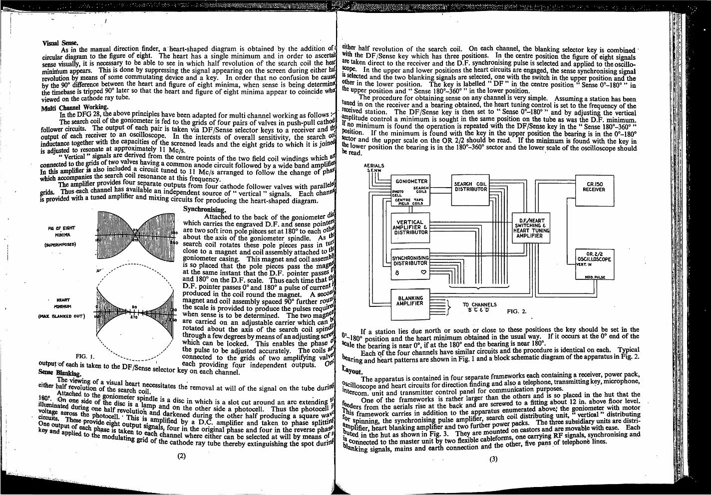
VisDal Sense.As in the manual direction finder, a heart-shaped diagram is obtained by the addition of
circular diagram to the figure of eight. The heart has a single minimum and in order to ascertaiisense visually, it is necessary to be able to see in which half revolution of the search coil the heafminimum appears. This is done by suppressing the signal appearing on the screen during either h^revolution by means of some commutating device and a key. In order that no confusion be causftby the 90® difference between the heart and figure of eight minima, when sense is being determine^the timebase is tripped 90® later so that the heart and figure of eight minima appear to coincide whdviewed on the cathode ray tube.Malti Channel Working.
In the DFG 28, the above principle have been adapted for multi channel working as follows •The semch coil of the goniometer is to the grids of four pairs of valves in push-pull cathc^
follower circuits. The ou^ut of each pair is taken via DF/Sense selector keys to a receiver and Iffoutput of each receivCT to an oscilloscope. In the interests of overall sensitivity, the search cojinductance together with me capacities of the screened leads and the eight grids to which it is join^is adjusted to resonate at approjumately 11 Mc/s." Vertical' centre points of the two field coil windings which ̂connected to Ae gnds , having a common anode circuit followed by a wide band amplifi^In this amplifier 18 mclu^ tuned to 11 Mc/s arranged to follow the change of pha^which accompames the search wil resonance at this frequency.
availahfJ^^^ outputs from four cathode follower valves with parallel^^ds. . Jhus-^ch lifi independent source of " vertical " signals. Each channfis iMTOvided with a P mixing circuits for producing the heart-shaped diagram.
Synchronising. . iAttached to the back of the goniometer ̂
which carries the engraved D.F. and sense point^are two soft iron pole pieces set at 180° to each oth ̂about the axis of the goniometer spindle. As ̂search coil rotates these pole pieces pass in tvijjclose to a magnet and coil assembly attached to JJ,goniometer casing. This magnet and coil assefliHJIS so placed that &e pole pieces pass the ihagi^jat the same instant that the D.F. pointer passesand 180° on the D.F. scale. Thus each time thatD.F. pointer passes 0° and 180° a pulse of current /produced in the coil round the magnet. A seco^jmagnet and coil assembly spaced 90° further runJjJthe scale is provided to produce the pulses requi^when sense is to be determined. The two magU^are carried on an adjustable carrier which canrotated about the axis of the search coil spin^through a few degrees by means of an adjusting scf^which can be locked. This enables the phase Jthe pulse to be adjusted accurately. The coils ̂
I. connected to the grids of two amplifying val^ joutput'ofe^histakentotheDF/^Pnca i . each providing four independent outputs. 0^s«n«e Bfanlrin. ' ^ey on each channel.
FU CF EIGHT
MINIMA
(superimposed)
HEART
rmeMUM
(MAX BUNKED OUT)
The *either ̂ J^^^^ution of the sewc^ removal at will of the signal on the tube durit*^Hlmnin^/i^i^® disc^i?a^a^l^ which is a slot cut around an arc extendingvoltage ̂ one half revolution an/5 '^® ^ photocell. Thus the photocell^circuii.^^^^® P??towU. * This is ^^® producing a square ̂CL TV*- A
phase splittingO . TQ , o-— ..j reverse phas^the modulating griH^Xr where either can be selected at will by means oy
e* ot the cathode ray tube thereby extinguishing the spot duriw
ne output^® ^jght output'simSk^^f^ ^ D.C. amplifier and taken to ̂and^nniili^ phase is taken to i original phase and four in the reverse phas^^ «na applied to the to each channel where eithpr Ko of «,;i "
(2)
®i|her half revolution of the search coil. On each channel, the blanking selector key is combined"^•th the DF/Sense key which has three positions. In the centre position the figure of eight signals^retaken direct to the receiver and the D.F. synchronising pulse is selected and applied to theoscillo-
In the upper and lower positions the heart circuits are engaged, the sense synchronising signal•^®^ and the two blanking signals are selected, one with the switch in the upper position and theother in the lower position. The key is labelled " DF " in the centre position " Sense 0° -180° " in
toe upper position and '* Sense 180° -360° " in the lower position.The procedure for obtaining sense on any channel is vepr simple. Assuming a station has beenin on the receiver and a bearing obtained, the heart tuning control is set to the frequency of the
^ived station. The DF/Sense key is then set to " Sense 0° -180° " and by adjusting the verticalJ®plitude control a minimum is sought in the same position on the tube as was the D.F. TniniTnnmjfno minimum is found the operation is repeated with the DF/Sense key in the " Sense 180° -360° "^sition. If the minimum is found with the key in the upper position the bearing is in the 0° -180°J^tor and the upper scale on the OR 2/2 should be read. If the minimum is found with the key in
lower position the bearing is in the 180° -360° sector and the lower scale of the oscilloscope should
AERIALSSENW
GONIOMETER
SCARCHPHOTO COILSCELL
CENTRE TAPSBELO COILS
SEARCH COILDISTRIBUTOR
VERTICALAMPLIFIER tDISTRIBUTOR
SYNCHRONISINGDISTRIBUTOR
8
D.R/HEARTSWITCHING CHEART TUNINGAMPLIFIER
BLANKINGamplifier
CR.I50RECEIVER
OR. 2/2OSCILLOSCOPEVERT. IN
MOD. PULSE
B} TO CHANNELSB" C 6 D" FIG. 2.
If a station lies due north or south or close to these positions the key should be set in the"-180° position and the heart minimum obtained in Ae usual way. If it occurs at the 0° end of the
the bearing is near 0° , if at the 180° end the bearing is near 180 . . .. . . , _ . .Each of the four channels have similar circuits and the procedure is idenUwl on each. T^ical
^fing and heart patterns are shown in Fig. 1 and a block schematic diagram of the apparatus in Fig. 2.ta
aooaratus is contained in four separate frameworks rach containing a reiver, power pack,SUiosIS™ at rt ci^rcuits for direction
spinning, the synchronising pulse amphfie^ se^n w?^plifier, heart blanking amplifier and two f L castors and are movable with ease. Eachi^ted in the hut as shown in Fig. 3. They are carrying RF signals, synchronising andL, Connected to the master umt by two flexible cablew , ^ telephone lines.^^anking signals, mains and earth connection and the otner, nve p .
(3)
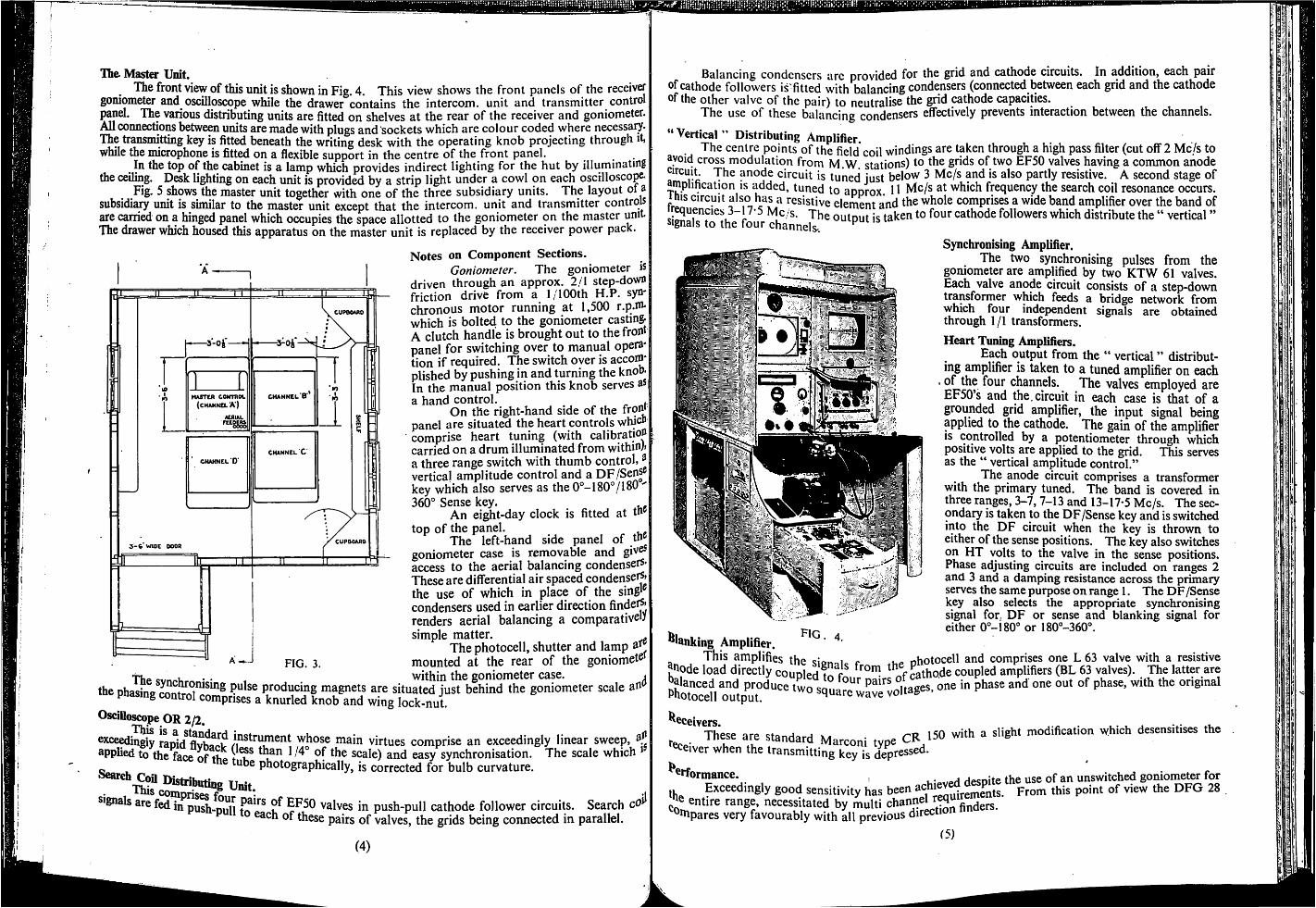
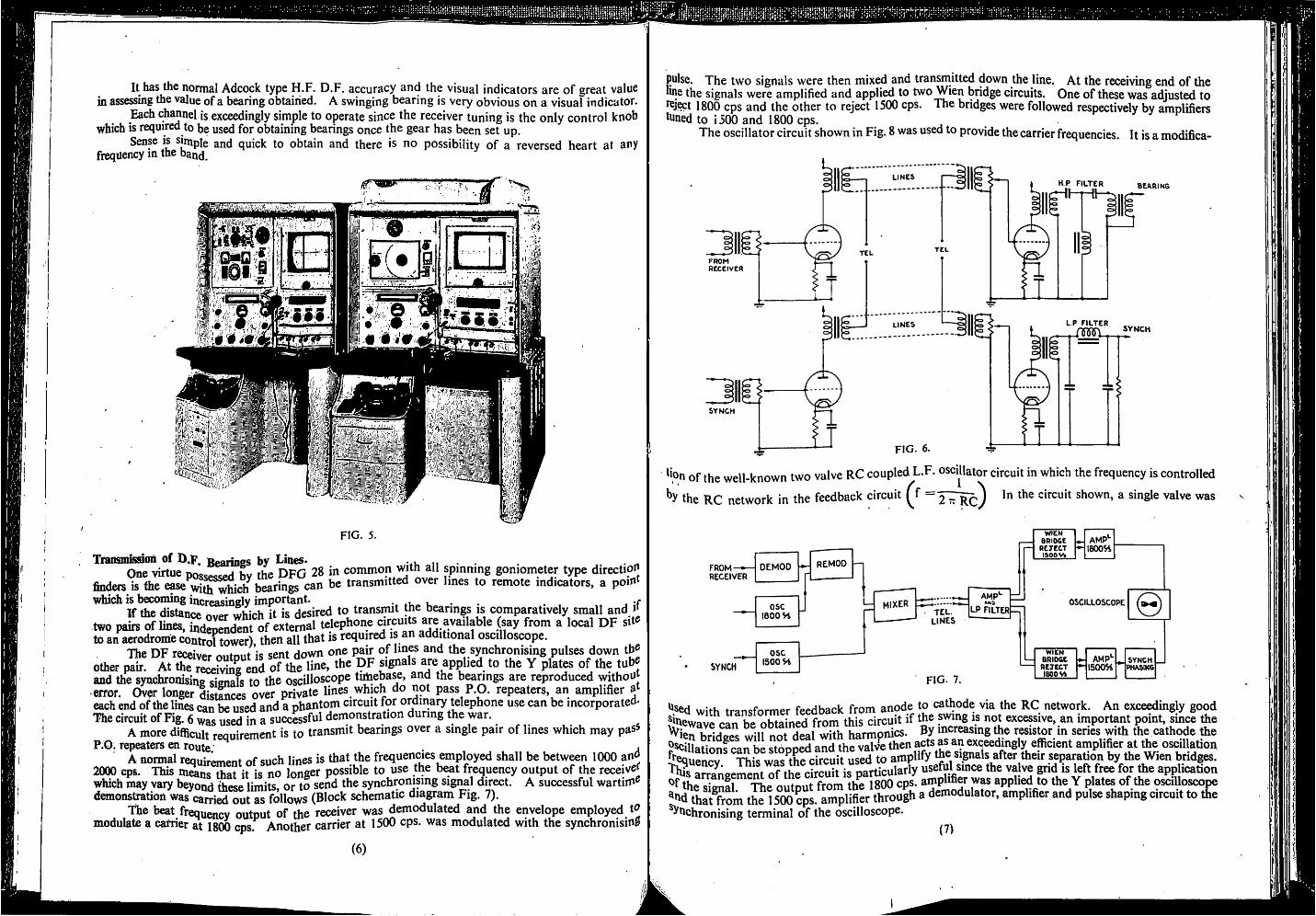
The Master Unit.The front view of this unit is shown in Fig. 4. This view shows the front panels of the receiver
goniometer and oscilloscope while the drawer contains the intercom, unit and transmitter controlpanel. The various distributing units are fitted on shelves at the rear of the receiver and goniometer.All connections between units are made with plugs and Sockets which are colour coded where necessary.The transmitting key is fitted beneath the writing desk with the operating knob projecting through it,while the microphone is fitted on a flexible support in the centre of the front panel.
^ In the top of the cabinet is a lamp which provides indirect lighting for the hut by illuminatingthe ceiling. Desk lighting on each unit is provided by a strip light under a cowl on each oscillosco^
Fig. 5 shows the master unit together with one of the three subsidiary units. The layout of asubsidia^ unit is similar to the master unit except that the intercom, unit and transmitter controlsare carried on a hinged panel which occupies the space allotted to the goniometer on the master unitThe drawer which housed this apparatus on the master unit is replaced by the receiver power pack.
Notes on Component Sections.Goniometer. The goniometer is
driven through an approx. 2/1 step-downfriction drive from a 1/100th H.P. synchronous motor running at 1,500 r.p.m-which is bolted to the goniometer castingA clutch handle is brought out to the frompanel for switching over to manual operation if required. The switch over is accomplished by pushing in and turning the knob.In the manual position this knob serves asa hand control.
On the right-hand side of the frompanel are situated the heart controls whicbcomprise heart tuning (with calibratjoacarried on a drum illuminated from withml'a three range switch with thumb control, ̂vertical amplitude control and a DF/SenS®key which also serves as the 0° -180° /180 '360° Sense key.
An eight-day clock is fitted attop of the panel.
The left-hand side panel of tn®goniometer case is removable andaccess to the aerial balancing condensers-These are differential air spaced condenser^'the use of which in place of the singlcondensers used in earlier direction finder^renders aerial balancing a comparativelysimple matter.
The photocell, shutter and lampmounted at the rear of the goniomet®'
the «!vnpKr« • • 1 within the goniometer case. ,the Dhasina producing magnets are situated just behind the goniometer scale ab"pnasing control comprises a knurled knob and wing lock-nut.OsciUoscope OR 2/2.exceedingly ranid^^vWu whose main virtues comprise an exceedingly linear sweep,applied to the face of ti,® 1 ^ scale) and easy synchronisation. The scale which '^ race of the tube photographically, is corrected for bulb curvature.
Distrttwu^ v^tconipris&s fV\ • *1signals are fed in push-pull to valves in push-pull cathode follower circuits. Search cO^
each of these pairs of valves, the grids being connected in parallel.
(4)
CHANNEL BMASTER CONTROL
(channel A)AERIALFCCPCRS
CHANNEL'C
CHANNEL° D
CUPDOARO3-6 WIDE DOOR
Balancing condensers are provided for the grid and cathode circuits. In addition, each pairof cathode followers is fitted with balancing condensers (connected between each grid and the cathodeof the other valve of the pair) to neutralise the grid cathode capacities.
The use of these balancing condensers effectively prevents interaction between the channels." Vertical " Distributing Amplifier.
The centre points of the field*coil windings are taken through a high pass filter (cut off 2 Mc/s toavoid cross modulation from M.W. stations) to the grids of two EF50 valves having a common anodecircuit. The anode circuit is tuned just below 3 Mc/s and is also partly resistive. A second stage ofamplification is added, tuned to approx 11 which frequency the search coil resonance occurs,this circuit also has a resistive element and the whole comprises a wide band amplifier over the band ofr^uencies 3-17-5 Mc/s. The output is taken to four cathode followers which distribute the " vertical "signals to the four channels-.
Synchronising Amplifier.The two synchronising pulses from the
goniometer are amplified by two KTW 61 valves.Each valve anode circuit consists of a step-downtransformer which feeds a bridge network fromwhich four independent signals are obtainedthrough 1 / I transformers.
Heart Tuning Amplifiers.Each output from the " vertical" distribut
ing amplifier is taken to a tuned amplifier on each. of the four channels. The valves employed areEF50 s and the, circuit in each case is that of agrounded grid amplifier, the input signal beingapplied to the cathode. The gain of the ampUfierIS controlled by a potentiometer through whichpositive volts are applied to the grid. This servesas the " vertical amplitude control."
The anode circuit comprises a transformerwith the primary tuned. The band is covered inthree ranges, 3-7,7-13 and 13-17-5 Mc/s. The secondary is taken to the DF/Sense key and is switchedinto the DF circuit when the key is thrown toeither of the sense positions. The key also switcheson HT volts to the valve in the sense positions.Phase adjusting circuits are included on ranges 2and 3 and a damping resistance across the primaryserves the same purpose on range 1. The DF /Sensekey also selects the appropriate synchronisingsignal for, DF or sense and blanking signal foreither 0° -180° or 180° -360° .
%
fig^ . 4.Janking Amplifier.This amplifies the ̂ ionoi r nhotocell and comprises one L 63 valve with a resis
Jhode load directly counleH r . f rathode coupled amplifiers (BL 63 valves). The latterbalanced and produce two cn naees one in phase and one out of phase, with the origl^hotocell output. '
Receivers.^ These are standard Marconi tvoe CR 150 with a slight modification which desensitises the®ceiver when the transmitting key is depressed.^®rformance. , desoite the use of an unswitched goniometer for
Exceedingly good sensitivity has been achi^^ h ^hg 28entire range, necessitated by multi channel r^uiremen .
^mpares very favourably with all previous direction(5)
ji; i
It has the normal Adcock type H.F. D.F. accuracy and the visual indicators are of ereat valuein assessing the value of a bearing obtained. A swinging bearing is very obvious on a visuaf indicator.
Each channel is exceedingly simple to operate since the receiver tuning is the only control knobwhich is required to for obtaining bearings once the gear has been set up.
Senp is simple and quick to obtain and there is no possibility of a reversed heart at anyfrequency in the band.
im 'i-.J
I
FIG. 5.
Transmisaoh of D.F. Bearincs by Lines. ♦u n • • .1One virtue posted bv the DFG 28 in common with all spinning goniometer type directionfindeis is the wift^ch bearings can be transmitted over lines to remote indicators, a point
which is becoming mcreasingly important. u • • • , v. j ;ftf the distance over which it is desired to transmit he barings is comparatively smalland d
two pairs of lines, inifelndent of external telephone circuits are available (say from a local DF sit«to an aerodrome control tower), then all that is required is a dditional oscilloscope.The DF receivpr rsntmit is sent down one pair of lines and the synchronising pulses down tb®other At S^'rS end of Ihe line, the DP signals are applied, to the Y plates of the tub'
and the synchronising signals to the oscilloscope timebase, and the bearings are reproduced withouterror. Over longer distoces over private lines which do not pass P.O. repeaters, an amplifier ateach end of the lines can be used and a phantom circuit for ordinary telephone use can be incorporated-The circuit of Fig. 6 wi us^ te Tsucilssful demonstration during the war.
A more difficult requirement is to transmit bearings over a single pair of lines which may pasSP.O. repeaters en route j
A normal requirement of such lines is that the frequencies employed shall be between 1000 an^2000 cps. This means that it is no longer possible to use the b^t frequency output of the receiverwhich may vary beyond these limits, or to send the synchronising signal direct. A successful wartim®demonstration was carried out as follows (Block schematic diagram Fig. 7).
the beat frequency output of the receiver was demodulated and the envelope employed tnmodulate a carrier at 1800 cps. Another carrier at 1500 cps. was modulated with the synchronising
(6)
pulse. The two signals were then mixed and transmitted down the line. At the receiving end of theiine the signals were amplified and applied to two Wien bridge circuits. One of these was adjusted tor®j%t 1800 cps and the other to reject 1500 cps. The bridges were followed respectively by amplifierstuned to 1500 and 1800 cps.
The oscillator circuit shown in Fig. 8 was used to provide the carrier frequencies. It is a modifica-
".1 BEARINGLINES
FROMRECEIVER
L P FILTER
SYNCH
FIG. 6.
SYNCH
Of the well-known two valve RC coupled L.F. osciUator circuit in which the frequency is controlledthe RC network in the feedback circuit ^f In the circuit shown, a single valve was
FROM-w-RECEIVER
DEMOD
OSC1600 Si
REMOD
SYNCH
OSC1500 Si
mixerTEL.lines
fig. 7.
amp'-LP FILTER
WIENBRIDGE AMP*-
REJECT •- IBOOSi1900 Vh
OSCILLOSCOPE 0WICN
BRIDGE AMP*- SYNCHREJECT I500S4 PHASING1800 Vh
t».sed with transformer feedback from anode to cathode via the RC network. An exce^ingly goodJinewave can be obtained from this circuit if the swing is not excessive, an important point, smce the^ien xxriU nnt Hftfll wlth haiTnonics. By increasing the resistor in senes with the cathode the?^cillations can be stopped and the valJe then acts as an exceedingly efficient ampUfier at the oscillationThis wa^tCchc^ to amplify the signals after their separation by the Wien bridges,^his thf^ rifcuit is oarticularly useful smce the valve grid is left free for the application
the^^f 1 The oiitnut from the 1800 cps. amplifier was applied to the Y plates of the oscilloscope"Id thatTrom the 1500V amplifier through a demodulator, amplifier and pulse shaping circuit to theSynchronising terminal of the oscilloscope.
(7)
It A
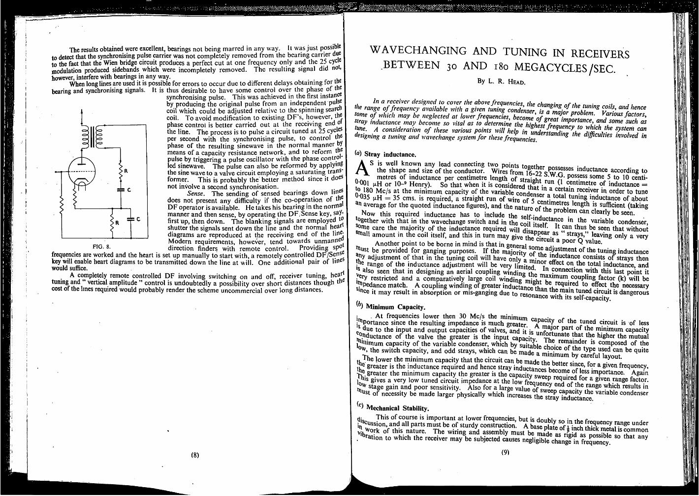
The results obtained were excellent, bearings not being marred in any way. It was just possibleto detect that the synchronising pulse carrier was not completely removed from the bearing carrier dueto the fact that the Wien bridge circuit produces a perfect cut at one frequency only and the 25 cyclemodulation produced sidebands which were incompletely removed. The resulting signal did not.however, interfere with bearings in any way.
When long lines are used it is possible for errors to occur due to different delays obtaining for tnebearing and synchronising signals. It is thus desirable to have some control over the phase of th
synchronising pulse. This was achieved in the first instanceby producing the original pulse from an independent pulscoil which could be adjusted relative to the spinning searcucoil. To avoid modification to existing DF's, however, th®phase control is better carried out at the receiving end othe line. The process is to pulse a circuit tuned at 25per second with the synchronising pulse, to control tnphase of the resulting sinewave in the normal manner bymeans of a capacity resistance network, and to reform thpulse by triggering a pulse oscillator with the phase controlled sinewave. The pulse can also be reformed by applybSthe sine wave to a valve circuit employing a saturating transformer. This is probably the better method since it doenot involve a second synchronisation. .
Sense. The sending of sensed bearings down hhdoes not present any difficulty if the co-operation of tnDF operator is available. He takes his bearing in the norrnhmanner and then sense, by operating the DF/Sense key, say»first up, then down. The blanking signals are employedshutter the signals sent down the line and the normal heardiagrams are reproduced at the receiving end of the lih^Modern requirements, however, tend towards unmannedirection finders with remote control. Providing spb
frequencies are worked and the heart is set up manually to start with, a remotely controlled DF/Sens^key will enable heart diagrams to be transmitted down the line at will. One additional pair of lib^®would suffice.
A completely remote controlled DF involving switching on and off, receiver tuning, heat^tuning and " vertical amplitude " control is undoubtedly a possibility over short distances though th^cost of the lines required would probably render the scheme uncommercial over long distances.
WAVECHANGING AND TUNING IN RECEIVERSBETWEEN 30 AND i8o MEGACYCLES/SEC.
(8)
By L. R. Head.
In a receiver designed to cover the above frequencies thp rhnnni*,,* *u 4 • ..range of frequency available with a given tuning condenser is a wninr
some of which may be neglected at lower frequencies^ become 'of ̂rent imfnrfn ^fious factors^^tray inductance may become so vital as to determine the hiehesf frfnuZrTt ^^^ ne. A consideration of these various points willhelfi„tZ{l^^^^^ system can^Psigning a tuning and wavechange system for these frequencies ^fficulties involved in
Stray inductance.AS is well known any lead connecting two points topptRpr • jthe shape and size of the conductor. Wires from q w inductance according tometres of inductance per centimetre length of straJoBt f 5 to 10 centi-
J'OOl jxH or 10-® Henry). So that when it is considered thni (1 centimetre of inductance =^c/s at the minimum capacity of the variable conHpncAr receiver in order to tune
■035 (xH = 35 cms. is required, a straight run of wire of S opr.? 1 tuning inductance of qboutaverage for the quoted inductance figures), and the natum u? sufficient (taking, Now this required induetanee has to inelude the s^inl ^
bgether with that in the wavechange switch and in the coil iIcp^p variable condenser,onie care the majority of the inductance required will that withoutbiall amount in the coil itself, and this in turn may give strays," leaving only a very
Another point to be borne in mind is that in general «?nm ^ ^ value,ust be provided for ganging purposes. If the majority nf the tuning inductance
by adjustment of that in the tuning coil will have only a minA ^^"ctance consists of strays then.be range of the inductance adjustment will be very limiteH / ®"cct on the total inductance, andJ also seen that in designing an aerial coupling winding thp pobnection with this last point it
restricted and a comparatively large coil winding mioht^K*"^^- ̂ °bpling factor (k) will be^pedance match. A coupling winding of greater inductance thn effect the necessary
bee it may result in absorption or mis-ganging due to rpcr.r.0 ^ tne mam tuned circuit is dangeroust. e to 10 resonance with its self-capacity.Minimum Capacity.
j . At frequencies lower then 30 Mc/s the minimum can»n't r uImportance since the resulting impedance is much greater. A m ' ° tuned circuit is of less
due to the input and output capacities of valves, and it ic part of the minimum capacityb.bductance of the valve the greater is the input caoacitv .^'^nate that the higher the mutual
1 biiruum capacity of the variable condenser, which by suitahlp aV, composed of thethe switch capacity, and odd strays, which can be made a minimum ̂ rarefuMayom"„ t he lower the minimum capacity that the circuit can be maHp tiiA . / *.J® greater is the inductance required and hence stray inductancp? Rpa ^ frequency,
greater the minimum capacity the greater is the capacity swepn rpn^^v ibtportance. Againj^is gives a very low tuned circuit impedance at the low freouencv ptirf^^f^R ^ given range factor.. m stage gain and poor sensitivity. Also for a large value of swppn oa ^^bge which results inbst of necessity be made larger physically which increases the stray SctLce condenser
Mechanical Stability.tli«^ of course is important at lower frequencies, but is donhlv ca ;« r..A«i cussion, and all parts must be of sturdy construction. A base nlate of i inrh range underVi.^ork of this nature. The wiring and assembly must be minf o ^. ration to which the receiver may be subjected causes negligible changf'fn fkqSScy®
(91


![c D . D J Vg Dc ] DcY =J] J 9 c.rJ] ] YYYJ==J ]J]c D. = ZJ ...d j vg dc ] dcy =j] j 9 c.rj] ] yyyj==j ]j]c d. = zj ] [ y = ] c cy. ] % =. . ¬ ¬ Ã Ú þ ü ý dcyj v y = vyjcj .kd](https://img.pdfslide.net/doc/110x75/5ecf5446872eca1ce71ee05b/c-d-d-j-vg-dc-dcy-j-j-9-crj-yyyjj-jc-d-zj-d-j-vg-dc-dcy-j.jpg)


![D H 6 9 A J ' D - / J + H , G H / ' D 9 D E ' ! A J E H ' , G …٧ oè‚£]](https://img.pdfslide.net/doc/110x75/5e5644631624bb634961d3b6/-d-h-6-9-a-j-d-j-h-g-h-d-9-d-e-a-j-e-h-g-oa.jpg)