Embed Size (px)
Citation preview
By designing the plates os self-supporting and removable by hand from the
unit makes the maintenance of the plates very easy. Such plates can be
cleaned using a scraper. Another alternative is withdrawing sludge very
rapidly. This causes sludge which is resting on the plates to dislodge.
Spraying the plates with a jet of water has the same effect.
2.3.6 FLOCCULATING IN LAMELLA SETTLERS.
It is well known that the ability of particles to settle out effectively
in a suspension is dependent only on the clarifying surface area avail
able. However; where flocculants are used to enhance settling the effec
tiveness of the settling is determined by the height through which the
particles fall. Through the coagulation of the flocculant with the par
ticles the settling velocity becomes faster and faster. The coagulation
process requires a certain amount of time (conventional flocculation
basins have a 30 to 45 minute holding time). The longer the time allowed,
the better the flocculant suspensions so formed. There is insufficient
time for floe to form in lamella settlers because the retention time is
so short (less than 10 minutes on average).
It is therefore important that the flocculating process is separated from
the sedimentation process and that proper flash mixing and coagulation
take place outside before the Influent enters the lamella settler (see
figure 17).
Natural flocculation without the addition of chemicals also takes place
in lamella settlers. This happens when thf* particles fall to the lower
wall of each platn and comp into contact with previously settled parti
cles. The additional contact of the falling particles in the plates with
the upflow of wastewater also facilitates the formation of denser, mote
readily settleable solids.
LITERATURE REVIEW 25
2.4 UP-RATING EXISTING HYDRAULIC ALLY OVERLOADED
SEDIMENTATION TANKS USING INCLINED PLATES
The use of inclined tubes and plates to up-rate existing installations
has been reported by Culp(1968), Gray(1975) and Van Vliet(1976).
Up-rating an existing installation can be done for various reasons:
o Plant extensions can be avoided if plates are introduced into the
settler, whilst still maintaining the desired effluent qualities.
o The cost of chemicals used to flocculate can be reduced.
o Improved effluent qualities may be required from the clarifier.
Culp(1968) used small tubes with a diameter of only a few centimetres
as the up-rating mechanism. Such tubes have a large wetted perimeter
relative to the wetted area and therefore readily create laminar flow
conditions within them, a fact borne out by the very low Re numbers
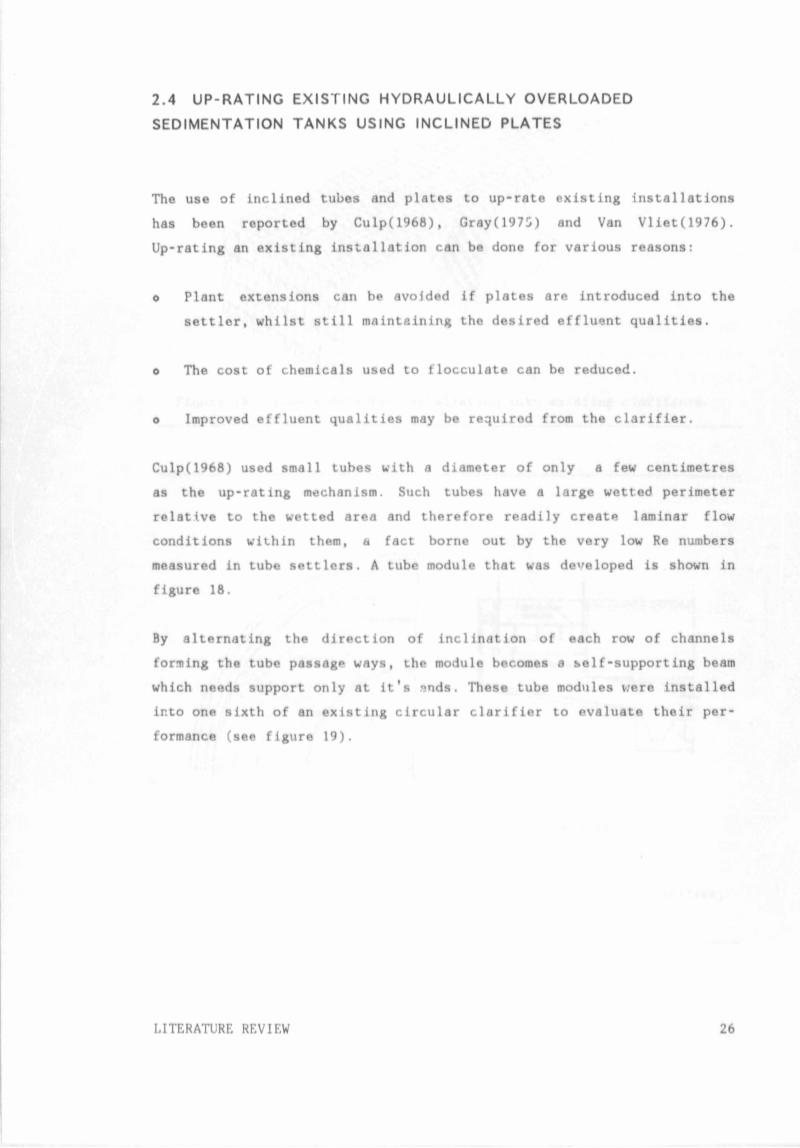
measured in tube settlers. A tube module that was developed is shown in
figure 18.
By alternating the direction of inclination of each row of channels
forming the tube passage ways, the module becomes a self-supporting beam
which needs support only at it's snds. These tube modules were installed
into one sixth of an existing circular clarifier to evaluate their per
formance (see figure 19).
LITERATURE REVIEW 26
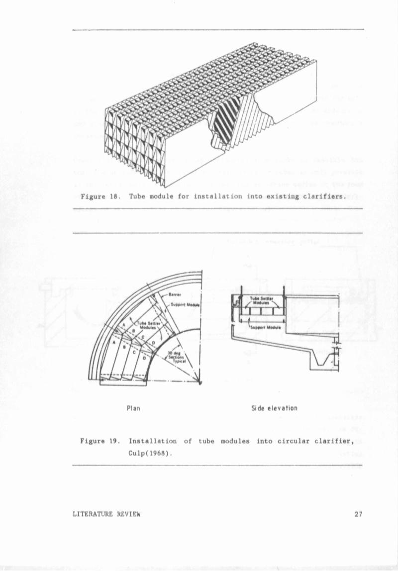
Figure 18. Tube module for installation into existing clarifiers.
Plan Side elevation
Figure 19. Installation of tube modules into circular clarifier,
Culp( 1968).
LITERATURE XEVIEW 27
Tube modules were also used as support beams for the upper modules so that
none of the clarifier surface lost due to nome other type of support
structure. The radial support beams were attached to the inlet well and
the effluent weir with PVC support brackets. Flow distribution tests
showed that the outer modules nearest the effluent weir received the bulk
of the flow. This did however not deter the efficiency of the modules to
any great extent and better effluent qualities than had been previously
obtained, where achieved.
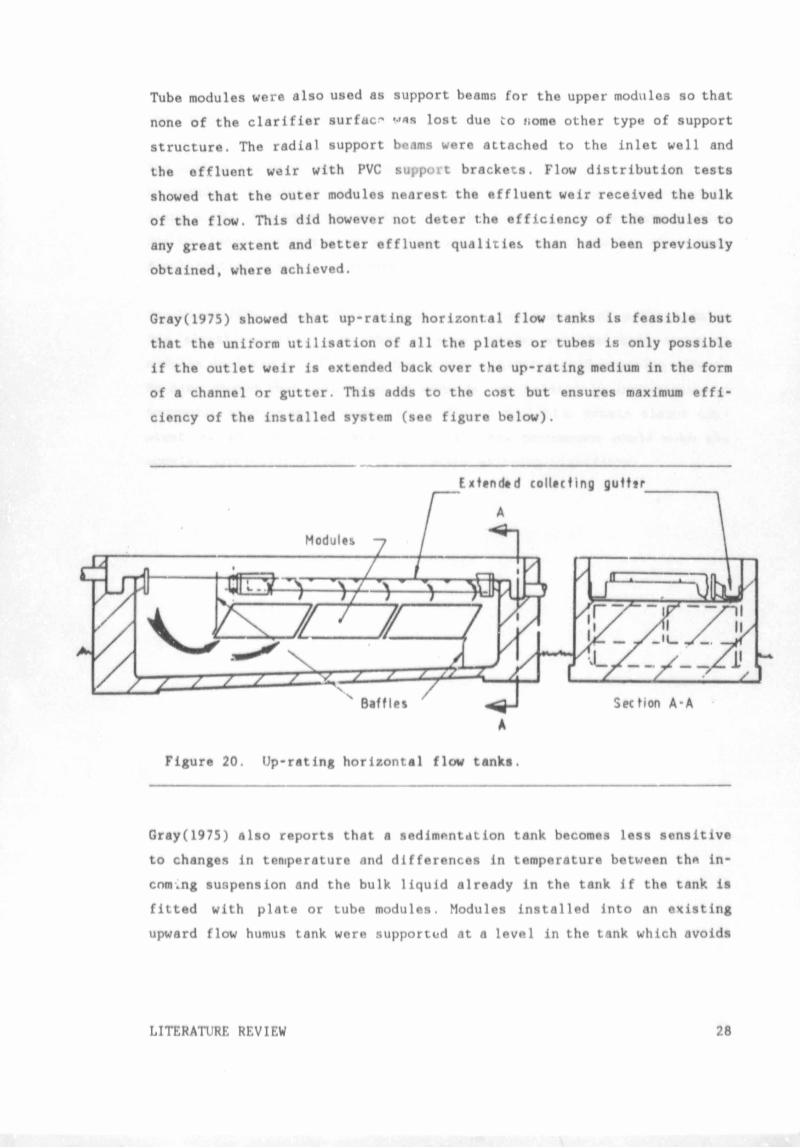
Gray(1975) showed that up-rating horizontal flow tanks is feasible but
that the uniform utilisation of all the plates or tubes is only possible
if the outlet weir is extended back over the up-rating medium in the form
of a channel or gutter. This adds to the cost but ensures maximum effi
ciency of the installed system (see figure below).
Figure 20. Up-rating horizontal flow tanks.
Gray(1975) also reports that a sedimentation tank becomes less sensitive
to changes in temperature and differences in temperature between the in
coming suspension and the bulk liquid already in the tank if the tank is
fitted with plate or tube modules. Modules installed into an existing
upward flow humus tank were supported at a level in the tank which avoids
LITERATURE REVIEW 28
interference from surface winds. Tube modules are reported to increase
the capacity of existing tanks by 50 to 150 percent.
The cost of the steel support structure for the modules (if required) must
be examined carefully. For the design of the supporting beam it must be
assumed that the tank is emptied, that the module weight may have doubled
due to sludge and that ft man may walk across it. Experience has shown that
a substantial beam is necessary.
Van Vliet(1976) shewed that in general the performance of plate modules
are slightly better than that of tube modules and thft both types of
modules inclined at 60° to the horizontal exhibit a self-cleaning effect.
He also showed that both types of modules are relatively insensitive to
hydraulic loading which means that effluent qualities remain almost con
stant. as the overflow rate increases. This phenomenon would make the
modules particularly useful in up-rating existing clarifiers.
LITERATURE REVIEW 29
2.5 CLARITY OF EFFLUENT REQUIRED IN MINING OPERATIONS.
It is the opinion of practical engineers in the mining industry that it
is impractical a3 well as uneconomical to achieve an effluent of extreme
purity and that ar. effluent which is "cloudy" is quite satisfactory. The
feeling is that this type of effluent does not greatly effect the opera
tional life of high-lift water pumps.
It has however been shown that a high concentration of suspended solids
in the effluent leads to the settling out of the solids in the inacces
sible clear water sumps, giving rise to problems in sump cleaning. Solids
in suspension also promote pump wear. Pump wear due to suspended solids
is dependent on the following:
o the fact that pump wear is directly proportional to the turbidity of
the water,
o the hardness of the particle relative to that of the metal from which
the pump components are manufactured,
o the head against which the pump is operating. This influences the
packing ring wear which is proportional to 1.5 times the power of the
seal pressure provided the particie siz« is less than 37ym. Larger
particle cizes produce higher packing ring wear.
o the particle mass and size, there being an Increase in wear rate when
the particle size reaches 40\ of the gap clearance between the
impeller and the housing.
Where the clarified water is to be used for underground human consumption
and in refrigeration circuits, suspended particles can adversely affect
the chlorination process and create scaling on condenser and evaporation
tubes. For such water usage the clarity of the effluent should approach
the Rand Water Board specifications of 5 mg/1. This is however difficult
to achieve without secondary filtering. An effluent with a turbidity of
LITERATURE REVIEW 30
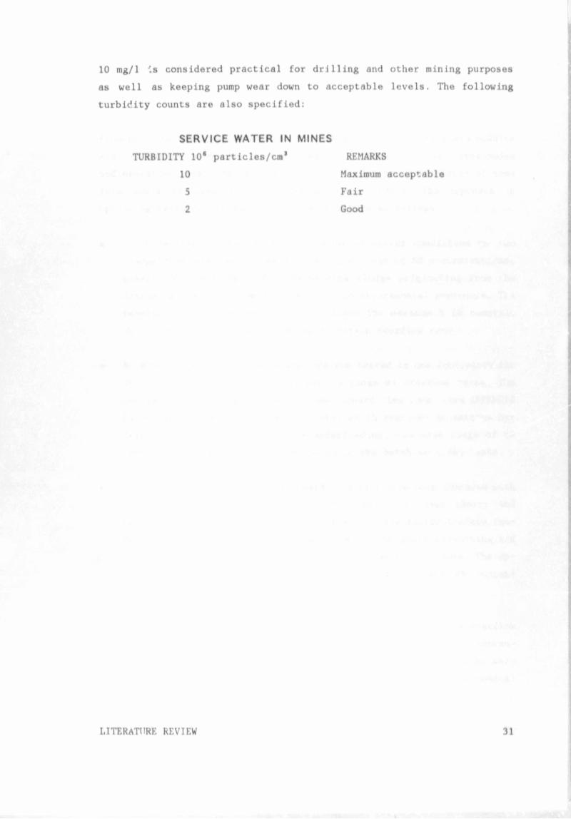
10 mg/1 is considered practical for drilling and other mining purposes
as well as keeping pump wear down to acceptable levels. The following
turbidity counts are also specified:
SERVICE WATER IN MINES
TURBIDITY 10* particles/cm* REMARKS
10 Maximum acceptable
5 Fair
2 Good
LITERATURE REVIEW 31
3.0 EXPERIMENTAL PROCEDURE FOLLOWED
From the literature, it is evident that some *orm of tuta or plate modules
are commonly used to >:p-rate existing hydraulical ly overloaded
sedimentation tanks. Hence it was envisaged that parallel plates of some
for"" would be used in the experimental procedure. The approach in
up-rating existing settling tanks was therefore as follows:
o Batch settling tests carried out undet quiescent conditions on the
sludge that was tested, were done for a range of SS concentrations,
namely 500 - 3000 mg/1. Dehydrated mine sludge originating from the
drains in a mine was used throughout the experimental procedure. The
results from these tests would indicate the maximum \ SS removals
which are physically possible for a certain overflow rate.
o An existing model sedimentation tank was tested in the laboratory for
it's % SS removal efficiencies over a range of overflow rates. The
sedimentation tank was a conventional upward flow tank (see APPENDIX
B) and vau subjected to overflow rates which resulted in extreme hy
draulic overloading as well as underloading. The same ranjr.e of SS
concentrations was used as was tested in the batch settling tests.
o The results obtained from the upward flow tank were then compared with
the batch settling results and the discrepancy between theory and
practice is quantified in the form of an upscale factor (safety fac
tor). The upscale factor is a measure of the short-circuiting and
turbulence which occurs in conventional sedimentation tanks. The up
scale factor was calculated for the range of influent SS concen
trations ttnd overflow rates tested.
o Ways of up-rating the upward flow sedimentation tank at tho overflow
rates where hydraulic overloading occurs were looked at. The conven
tional forms of up-rating, namely using plate or tube modules rere
discarded for reasons discussed in CHAPTER 5. A unique type of conical
EXPERIMENTAL PROCEDURE FOLLOWED 32
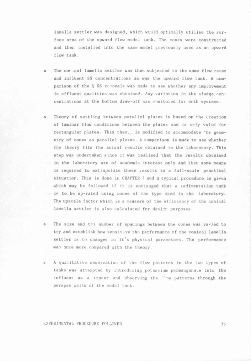
lamella settler was designed, which would optimally utilise the sur
face area of the upward flow model tank. The cones were constructed
and then installed ir.tc the same model previously used as an upward
flow tank.
o The cor ical lamella settler was then subjected to the same flow rates
and influent SS concentrations as was the upward flow tank. A com
parison of the % SS renovals was made to see whether any improvement
in effluent qualities was obtained. Any variation in the sludge con
centrations at the bottom draw-off was monitored for both systems.
o Theory of settling between parallel plates is based on the creation
of laminar flow conditions between the plates and is only valid for
rectangular plates. This theo.,, is modified to accommodate * he geom
etry of cones as parallel plates. A comparison is made to see whether
th*> theory fits the actual results obtained in the laboratory. This
step was undertaker, since it was realiseJ that the results obtained
in the laboratory are of academic interest only and that some means
is required to extrapolate these xesults to a full-scale practical
situatior. This is done in CHAPTER 7 and a typical procedure is given
which may be followed if it is envisaged that a sediment it ion tank
is to be up-rated using cones of the type used in the laboratory.
The upscale factor which is a measure of the efficiency of the conical
lamella settler is also calculated for design purposes.
o The size and thi number of spacings between the cones was varied to
try and establish how sensitive tho performance of the conical lamella
settler is to changes in it's physical parameters. The performance
was once more compared with the theory.
o A qualitative observation of the flow patterns in the two types of
tanks was attempted by introducing potassium permanganate into the
influent as a tracer and observing the '"’ow patterns through the
perspex walls of the model tank.
EXPERIMENTAL PROCEDURE FOLLOWED 33
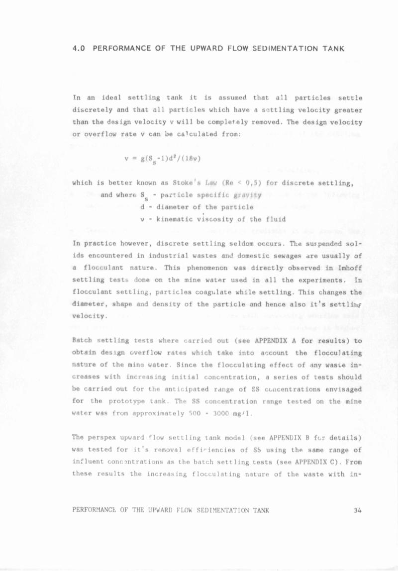
4.0 PERFORMANCE OF THE UPWARD FLOW SEDIMENTATION TANK
In an ideal settling tank it is assumed that all particles settle
discretely and that all particles which have a settling velocity greater
than the design velocity v will be completely removed. The design velocity
or overflow rate v can be calculated from:
v * g(S -l)d*/(18v)
which is better known as Stoke's Law (Re < 0,5) for discrete settling,
and wherti Ss - particle specific gravity
d - diameter of the particle
v - kinematic viscosity of the fluid
In practice however, discrete settling seldom occurs. The suspended sol
ids encountered in industrial wastes and domestic sewages dre usually of
a flocculant nature. This phenomenon was directly observed in Imhoff
settling tests done on the mine water used in all the experiments. In
flocculant settling, particles coagulate while settling. This changes the
diameter, shape and density of the particle and hence also it's settliiif
velocity.
Batch settling tests where carried out (see APPENDIX A for results) to
obtain design overflow rates which take into account the flocculating
nature of the mino water. Since the flocculating effect of any waste in
creases with increasing initial concentration, a series of tests should
be carried out for the anticipated range of SS concentrations envisaged
for the prototype tank. The SS concentration range tested on the mine
water was from approximately 500 - 3000 mg/1.
The perspex upward flow settling tank model (see APPENDIX B for details)
was tested for it's removal efficiencies of SS using the same range of
influent concentrations as the batch settling tests (see APPENDIX C). From
these, results the increasing flocculating nature of the waste with in-
PERFORMANCL OF THE UPWARD FLOW SEDIMENTATION TANK 34
4.0 PERFORMANCE O F THE UPWARD FLOW SEDIMENTATION TANK
In an ideal settling tank it is assumed that all particles settle
discretely and that all particles which have a settling velocity greater
than the design velocity v will be completely removed. The design velocity
or overflow rate v can be calculated from:
v = g(S -1)d*/(18v)
S
which is better known as Stoke's Law (Re < 0,5) for discrete settling,
and where S - particle specific gravity
s
d - diameter of the particle
v - I inematic viscosity of the fluid
In practice however, discrete settling seldom occurs. The suspended soi-
i encountered in industrial wastes and domestic sewages are usually of
a llocculant nature. This phenomenon was lirectly obsctved in Imhoff
settling tests done on the mine water used in all the experiments. In
flocculant settling, particles coagulate while settling. This changes the
diameter, shape and density of the particle and hence also it's settling
velocity.
Batch settling tests whete carried out (see APPENDIX A for results) to
obtain design overflow rates which take into account the flocculating
nature of the mine water. Since the flocculating effect of any waste in
creases with increasing initial concentration, a series of tests should
be carried out for the anticipated range of SS concentrations envisaged
for the prototype tank. The SS concentration rango tested on the mine
water w.is from approximately 500 - 3000 mg/1.
The perspex upward flow settling tank model (see APPENDIX B for details)
was tested for it's rerroval efficiencies of SS using the same range of
influent concentrations as the batch settling tests (see APPENDIX C). From
these results the increasing flocculating nature of the waste with in
PERFORMANCE OF THE UPWARD FLOW SEDIMENTATION TANK 34
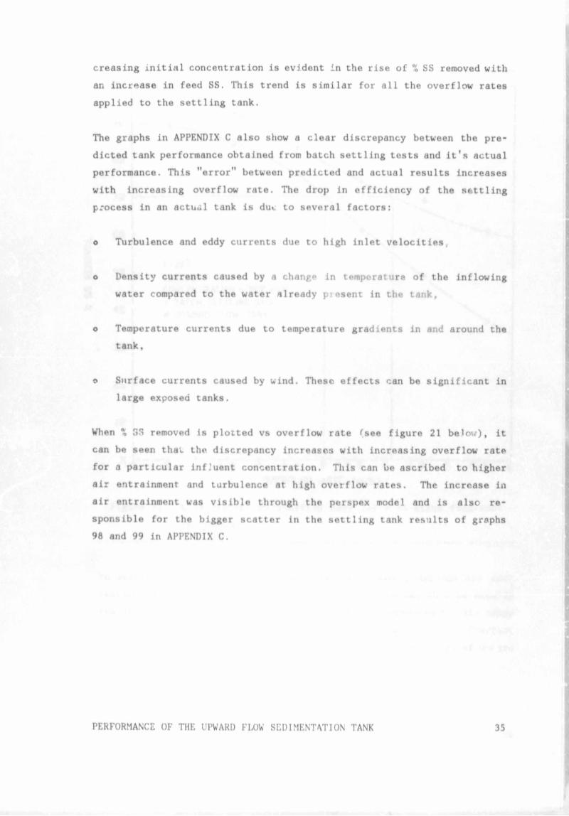
creasing initial concentration is evident in the rise of X SS removed with
an increase in feed SS. This trend is similar for all the overflow rates
applied to the settling tank.
The graphs in APPENDIX C also show a clear discrepancy between the pre
dicted tank performance obtained from batch settling tests and it's actual
performance. This "error" between predicted and actual results increases
with increasing overflow rate. The drop in efficiency of the settling
process in an actual tank is dut to several factors:
o Turbulence and eddy currents due to high inlet velocities,
o Density currents caused by a change in temperature of the Inflowing
water compared to the water already piftsent in the tank,
o Temperature currents due to temperature gradients in and around the
tank,
© Surface currents caused by wind. These effects can be significant in
large exposed tanks.
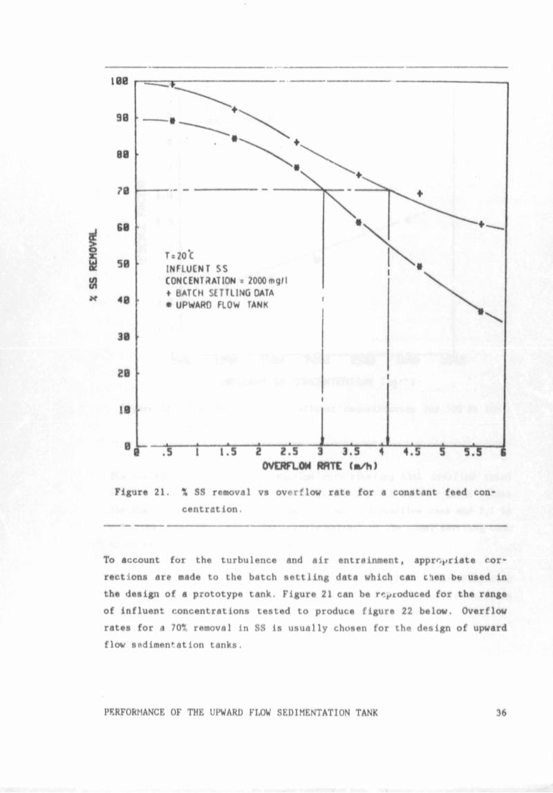
When X 3S rpmoved is plotted vs overflow rate (see figure 21 below), it
can be seen that the discrepancy increases with increasing overflow rate
for a particular inf.'uent concentration. This can be ascribed to higher
air entrainment and turbulence at high overflow rates. The increase in
air entrainment was visible through the perspex model and is also re
sponsible for the bigger scatter in the settling tank results of graphs
98 and 99 in APPENDIX C.
PERFORMANCE OF THE UPWARD FLOW SEDIMENTATION TANK 35
X SS
REHOVRL
Figure 21. X SS removal vs overflow rate for a constant feed con
centration .
To account for the turbulence and air entrainment, appropriate cor
rections are made to the batch settling data which can d e n be used in
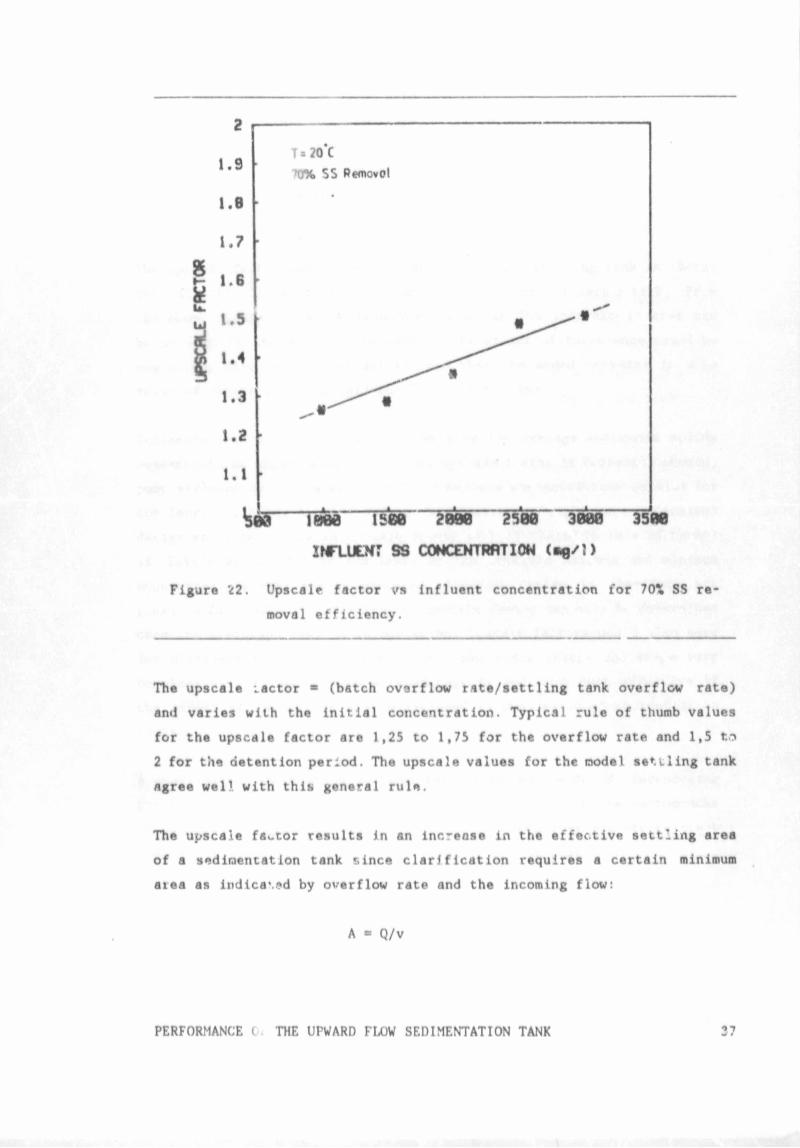
the design of a prototype tank. Figure 21 can be reproduced for the range
of influent concentrations tested to produce figure 22 below. Overflow
rates for a 70* removal in SS is usually chosen for the design of upward
flow Sftdimen*:ation tanks.
PERFORMANCE OF THE UPWARD FLOW SEDIMENTATION TANK 36
2
1.9
l.B
1.7
*
►— 1. b
*
1.5
I1.4
1.3
1.2
1.1
t o --- IBM---ism ---S W - ' « W ---30OT---3500
INTLUtSr S3 COHCDflRATION (•«/:)
Figure 22. Upscale factor vs influent concentration for 70\ SS re
moval efficiency.
The upscale :actor * (batch ovarflow rate/sett1ing tank overflow rate)
and varies with the initial concentration. Typical rule of thumb values
for the upscale factor are 1,25 to 1,75 for the overflow rate and 1,5 ta
2 for the detention period. The upscale values for the model settling tank
agree well with this general rule.
The upscale factor results in an increase in the effective settling area
of a sedimentation tank *.ince clarification requires a certain minimum
aiea as indica\.*d by overflow rate and the incoming flow:
A = Q/v
PERFORMANCE ( THE UPWARD FLOW SEDIMENTATION TANK
where A - sedimentation area required
Q - influent flow rate
v - overflow rate for a critical particle
size in discrete settling or overflow
rate for a certain % SS removal in
flocculant settling.
The upscale factor ar.d hence the turbulence in a settling tank is there
fore directly linked to the size and hence the cost of such a tank. From
the above figure it can be seen that an up to 50% increase in area can
ba avoided in the upward flow tank if the effect of turbulence could be
neglected. Also it is important to note that the added increase in area
required varies with the influent SS concentration.
Sedimentation uni "e usually designed for average suspended solids
concentrations whici. that if the upscale factor is correctly chosen,
poor effluent qualifies will result if maximum concent .ations persist for
any length of time. A conservative (but correspondingly more expensive)
design would be to use an upscale factor of 1,75 (based on rule of thumb)
if little or no data is available on the possible maximum and minimum
concentrations that can be expected. Accurate design is therefore not
possible for r single unit since the upscale factor can only be determined
oncc the prototype -ank is in operation. Upscale actors would al:.*o vary
for different types of sedimentation tanks si * inlets and shape va:'v
considerably. It would thus be advantageous ai.d ~'ore cost efi'.ctive if
the effect of turbulence can be excluded in the design of st ’imentation
tanks.
A qualitative observation of the turbulence was made by introducing
potassium pei ir.anganate into the perspex model tank. From the photographs
in APPENDIX D it can be seen that plug flow conditions are non-existent
and that considerable mixing takes place in the settler.
PERFORMANCE OF THE UPWARD FLOW SEDIMENTATION TANK 38
5.0 DESIGN AND DEVELOPMtNT OF THE CONICAL LAMELLA SETTLER
5.1 SOME CONVENTIONAL UP-RATING CONFIGURATIONS
The most common and extensively tested method of up-rating settling tanks
is to install tube or plate modules which cover the settling surface area
of the tank. The modules usually come in rectangular blocks (see LITERA
TURE REVIEW) and are installed in sections into the tank. This however
poses some practical problems when the intention is to install them into
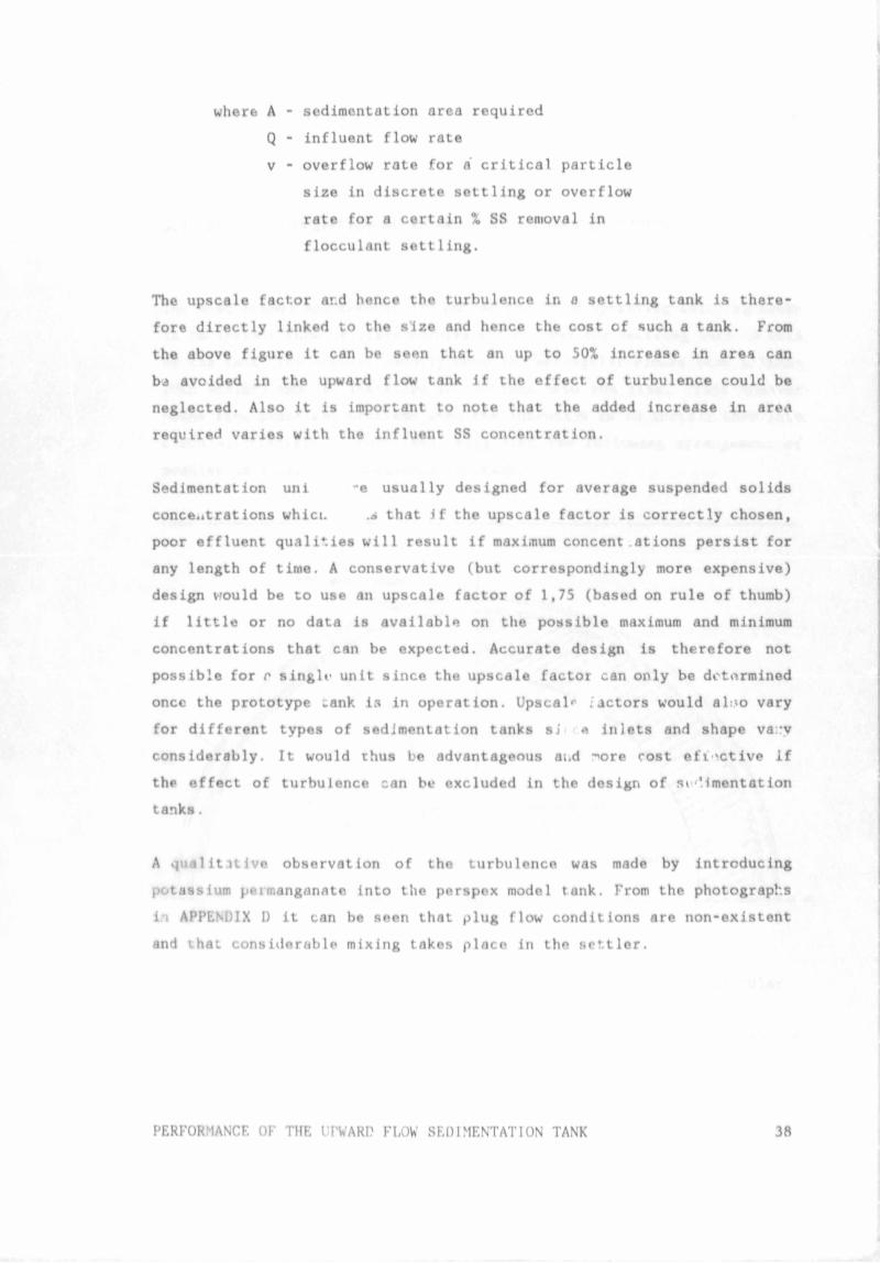
circular clarifiers. Culp(1968) suggested the following arrangement of
modules jn a circular sedimentation tank:
Figure 23. Plan view of module arrangement in a circular
sedimentation tank.
DFSIGN AND DEVELOPMENT OF THE CONICAL LAMELLA SETTLER 39
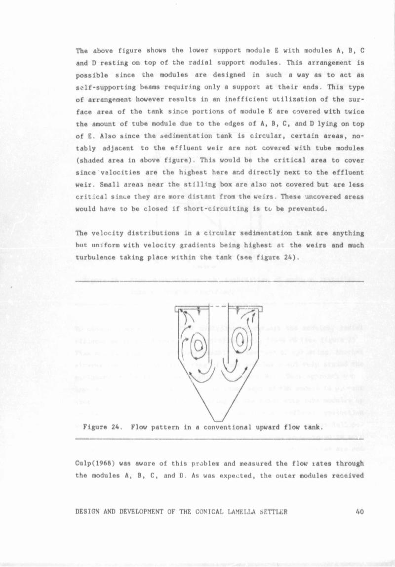
The above figure shows the lower support module E with modules A, B, C
and D resting on top of the radial support modules. This arrangement is
possible since the modules are designed in such a way as to act as
self-supporting beams requiring only a support at their ends. This type
of arrangement however results in an inefficient utilization of the 3ur-
face area of the tank since portions of module E are covered with twice
the amount of tube module due to the edges of A, B, C, and D lying on top
of E. Also since the sedimentation tank is circular, certain areas, no
tably adjacent to the effluent weir are not covered with tube modules
(shaded area in above figure). This would be the critical area to cover
since velocities are the highest here ar.d directly next to the effluent
weir. Small areas near the stilling box are also not covered but are less
critical since they are more distant from the weirs. These uncovered are&s
would have to be closed if short-circuiting is to be prevented.
The velocity distributions in a circular sedimentation tank are anything
but uniform with velocity gradients being highest at the weirs and much
turbulence taking place within the tank (see figure 24).
Figure 24. Flow pattern in a conventional upward flow tank.
Culp(1968) was aware of this problem and measured the flow rates through
the modules A, B, C, and D. As was expected, the outer modules received
DESIGN AND DEVELOPMENT OF THE CONICAL LAMELLA isETTLLR 40
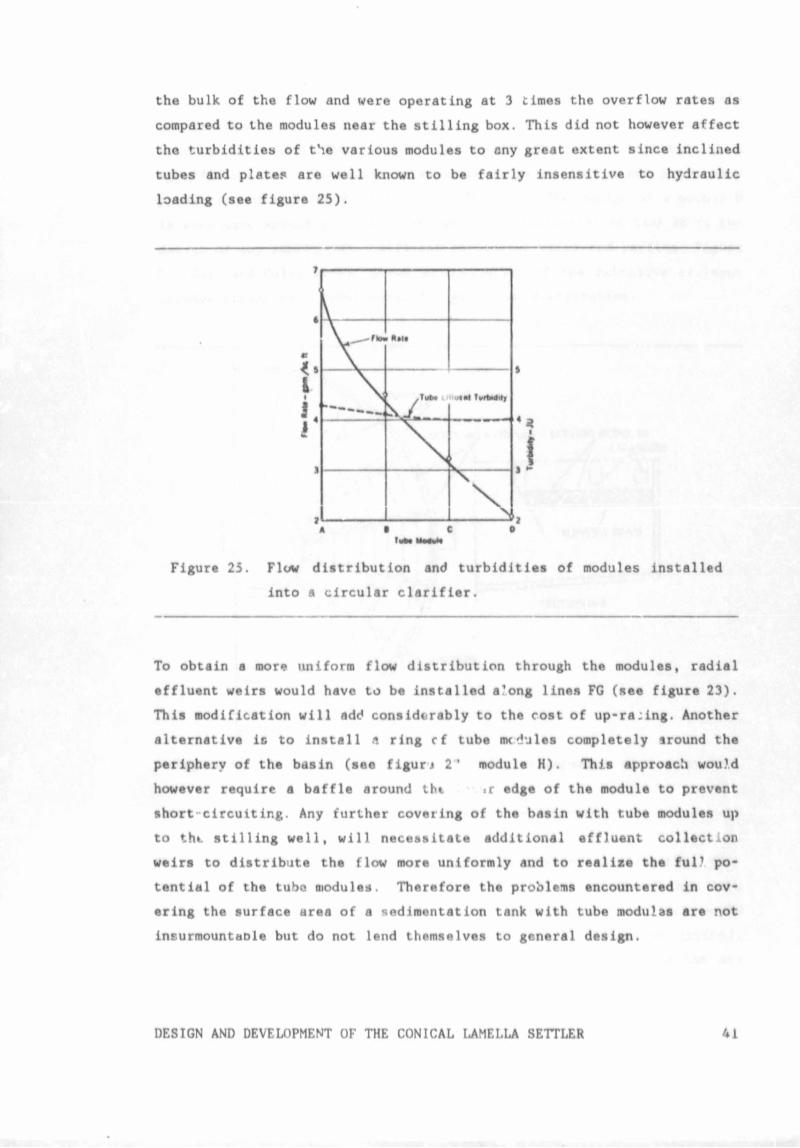
the bulk of the flow and were operating at 3 times the overflow rates as
compared to the modules near the stilling box. This did not however affect
the turbidities of the various modules to any great extent since inclined
tubes and plates are well known to be fairly insensitive to hydraulic
loading (see figure 25).
Figure 25. Flow distribution and turbidities of modules installed
into a circular clarifier.
To obtain a more uniform flow distribution through the modules, radial
effluent weirs would have to be installed a'ong lines FG (see figure 23).
This modification will add considerably to the cost of up-ra:ing. Another
alternative is to install a ring cf tube nx^ules completely sround the
periphery of the basin (see figurj 2 ’ module H). This approach would
however require a baffle around thi «r edge of the module to prevent
short-circuiting. Any further covering of the basin with tube modules up
to thi. stilling well, will necessitate additional effluent collection
weirs to distribute the flow more uniformly and to realize the ful? po*
tential of the tube modules. Therefore the problems encountered in cov*
erlng the surface area of a sedimentation tank with tube modulas are not
insurmountaDle but do not lend themselves to general design.
DESIGN AND DEVELOPMENT OF THE CONICAL LAMELLA SETTLER 41
The modules A t5 E are easily manufactured but the arrangement loses it's
attractiveness when the wide variation in diameter of settling tanks in
practice is taken into account. This means that every situation is a
specific one and will require a separate detailed design and hence mess
production of modules A to E is not feasible. The design of a module H
is even more specific to the diameter of the sedimentation tank as is the
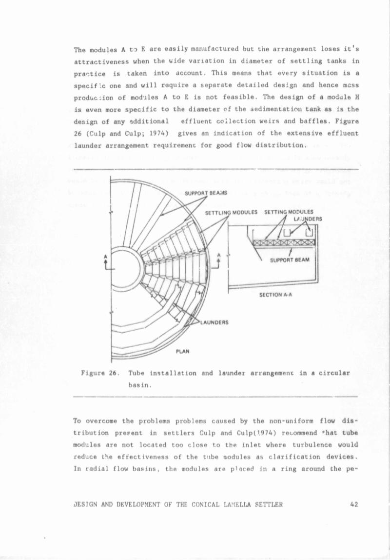
design of any additional effluent collection weirs and baffles. Figure
26 (Culp and Culp; 1974) gives an indication of the extensive effluent
launder arrangement requirement for good flow distribution.
Figur* 26. Tub« installation and launder arrangement in a circular
basin.
To overcome the problems problems caused by the non-uniform flow dis
tribution present in settlers Culp and Culp(l974) recommend *-hat tube
modules are not located too close to the inlet whore turbulence would
reduce the efrectivenuss of the tube modules as clarification devices.
In radial flow basins, the modules are placed in a ring around the pe
JESIGN AND DEVELOPMENT OF THF. CONICAL LAMELLA SETTLER 42
riphery leaving an open area around the stilling box to dissipate inlet
turbulence. The physical dimensions of the tube modules and the uneven
distribution of velocities within the tank result in up-rating config
urations which do not fully implement the clarification capabilities o.f
the tubes or the entire available surface area which could be covered with
tubo modules. Often additional costs in the form of effluent launders and
baffles are also incurred.
What wou’ therefore be Ideal is some type of mechanism which is not in
fluenced by the velocity gradients formed by the inlet and is also totally
reproducible for any type of tank shape or size. Also the design procedure
would be simplified since additional effluent collection weirs would not
be required. Such an idetl mechanism would be a cheap form of up-rating
since it lends itself to mass production.
DESIGN AND DEVELOPMENT OF THE CONICAI. LAMELLA SF.TTijbR 43
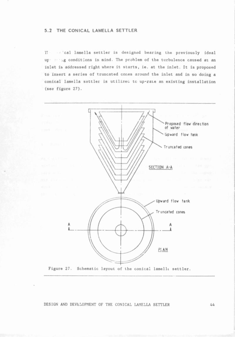
5.2 THE CONICAL LAMELLA SETTLER
TJ cal lamella settler is designed bearing the previously ideal
up • :.g conditions in mind. The problem of the turbulence caused at an
inlet is addressed right where it starts, ie. at the inlet. It Is proposed
to insert a series of truncated cones around the inlet and in so doing a
conical lamella settler is utilize''! tc up-xate an existing installation
(see figure 27).
Figure 27. Schematic layout of the conical lamellt settler.
DESIGN AND DEVELOPMENT OF THE CONICAL LAMELLA SETTLER 44
The above arrangement makes optimal use of the available settling surface
area of a sedimentation tunk but raises a number of questions:
o Water flow direction
As the inlet is in the center and the weirs on the periphery, a counter
current flow regime between influent and sludge is established This type
of system was deemed as the most advantageous for reasons given in the
LITERATURE REVIEW.
o Angle of inclination of cones
From the LITERATURE REVIEW it is apparent that an angle of a = 55° pro
vides for efficient continuous de-sludging in counter current flow sys
tems. Hence this angle is also adopted for the truncated cones.
o Removal of sludge
As described in the literature survey, the sludge settles on the lower
surface of the inclined plates and the slides down the plate in the op
posite direction to the incoming feed suspension. The fact that the cones
are stacked one on top of each other poses some problems with sludge re
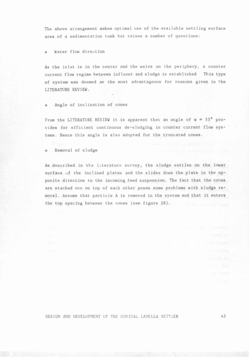
moval. Assume that particle A is removed in the system and that it enters
the top spacing between the cones (see figure 28).
DESIGN AND DEVELOPMENT OF THE CONICAL LAMELLA SETTLER 45
To de- sludging
Figure 28 Flow paths of particles between conical plates.
The particle will settle on the lowei turface of the the first cone
spacing and will then slide down this surface due to the action of grav
ity. As it falls past the next plate spacing (B) it will again be washed
between the cones by the incoming suspension of spacing B. Once again the
particle will settle on the surface of the lower cone just to be
re-suspended into spacing C. Hence the particle will only be removed from
the system once it passes plate spacing D.
Such a system of sludge removal has the potential to work but problems
will be experienced in the lower plote spacings since these will have to
remove the SS from the water of the top spacings as well as from their
own incoming suspension. This will result in a rapid progressive blocking
from the lower cone to the upper cone and hence the system has failed as
a continuous de-sludging system. Ideally therefore, once a particle has
settled it should not b« re-suspendeo but must be completely removed from
the system. Such a completely removed particle would follow a typical flow
path such as particle E, as indicated in the above figure.
DESIGN AND DEVELOPMENT OF THE CONICAL LAMELLA SETTLER 46
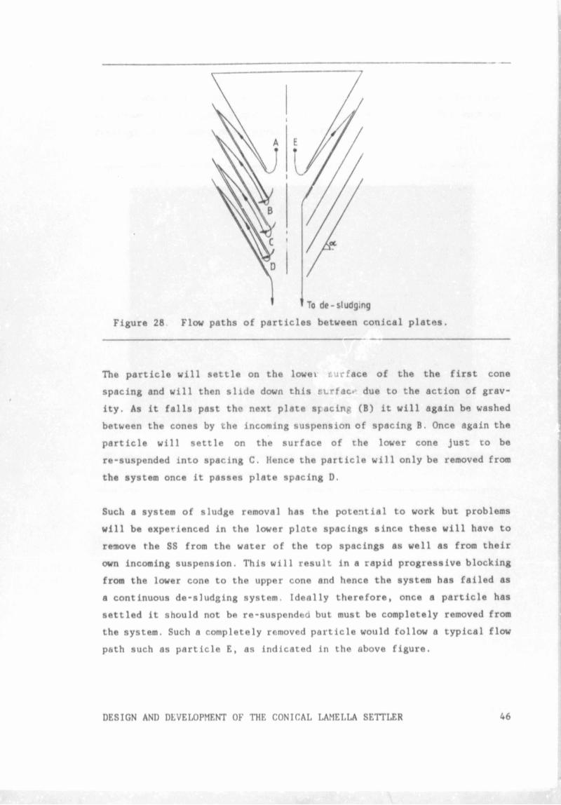
The flow path of particle E is achie' ** ’ in the conical lamella settler
by channeling the sludge into a seri* gutters to the bottom where it
is de-sludged. This results in a mo- » to the shape of the cone
as shown in the photographs in . ie 29 and 30 and in the working
drawings of the model cones given in APPENDIX E.
Figure 29. Photograph showing the lamella cone with triangular gut
ter arrangement.
DESIGN AND DEVELOPMENT OF THE CONICAL LAMELLA SETTLER 47
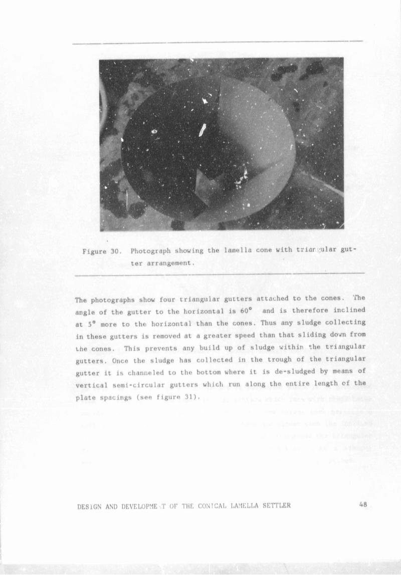
Figure 30. Photograph showing the lamella cone with triar -ular gut
ter arrangement.
The photographs show four triangular gutters attached to the cones. The
angle of the gutter to the horizontal is 60° and is therefore inclined
at 5° more to the horizontal than the cones. Thus any sludge collecting
in these gutters is removed at a greater speed than that sliding down from
the cones. This prevents any build up of sludge within the triangular
gutters. Once the sludge has collected in the trough of the triangular
gutter it is channeled to tho bottom where it is de-sludged by means of
vertical semi-circular gutters which run along the entire length of the
plate spacings (see figure 31).
DESIGN AND DEVELOPMENT OF THE CONTCAL LAMELLA SETTLER
To de-sludging
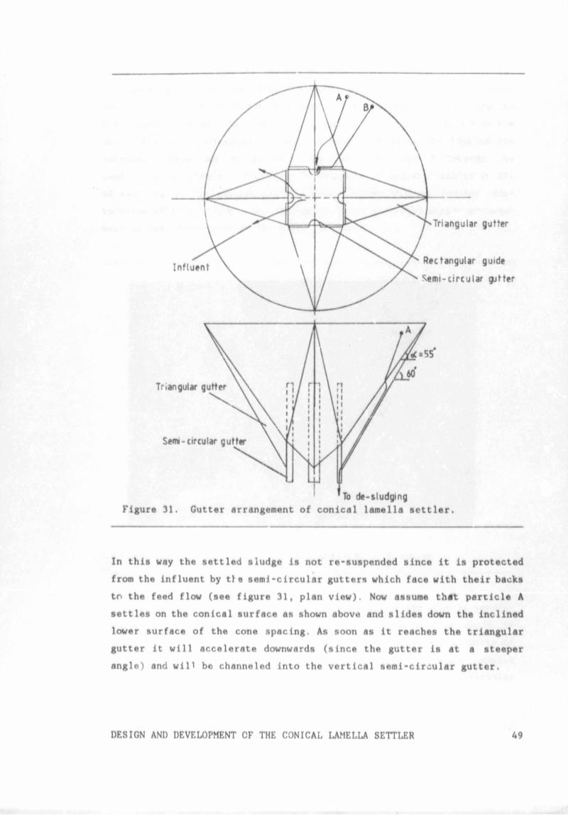
Figure 31. Gutter arrangement of conical lamella settler.
In this way the settled sludge is not re-suspended since it is protected
from the influent by tie semi-circular gutters which face with their backs
to the feed flow (see figure 31, plan view). Now assume that particle A
settles on the conical surface as shown above and slides down the inclined
lower surface of the cone spacing. As soon as it reaches the triangular
gutter it will accelerate downwards (since the gutter is at a steeper
angle) and will be channeled into the vertical semi-circular gutter.
DESIGN AND DEVELOPMENT OF THE CONICAL LAMELLA SETTLER 49
A particle settling on the conical surface might however not reach the
triangular gutter in time to be channeled into the semi-circular gutter
and will therefore slide over the edge of the cone and be washed into the
plate spacing below. To capture this type of particle (particle B in the
above figure), rectangular guides are installed along the lips of the
entrance. These act as guides for particles type B towards the
semi-circular gutters The above arrangement of gutters results in all
SS settling on the con.:al surface being removed without further dis
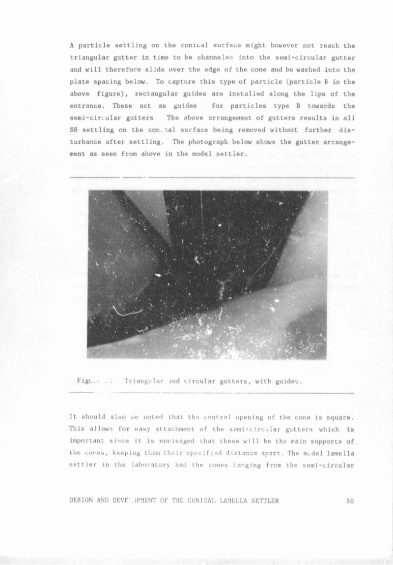
turbance after settling. The photograph below shows the gutter arrange
ment as seen from above in the model settler.
Figi..; . i Triangular m d circular gutters, with guide**.
It should also oe noted that the central opening of the cone is square.
This allows for easy attachment of the semi-circular gutters which is
important since it Is envisaged that these will be the main supports of
the cones, keeping them their specified distance apart. The mcdel lamella
settler in the laboratory had the cones I anging from the semi-circular
DESIGN AND DEVF\JPMENT OF THE CONICAL LAMELLA SETTLER 50
gutters which had teeth cut into them into which the cones where slotted.
In practice the cones would be supported by the vcitical connecting plates
(see APPENDIX E) and the central semi-circular gutters which would act
as struts. The gutters and the connecting plates would slot into the
cones which makes the changing of the plate spacing a simple process of
just sliding the cones up or down as required.
Apart from channeling sludge, the triangular gutters also serve other
purposes. Without the triangular gutter arrangement, sludge would con
centrate at the inlet since it is all sliding down towards this focal
point. The triangular gutters however increase the surface area on which
the sludge can settle and remove it faster than the cones. In this way
any possible blocking problems at the inlet are prevented. The triangular
gutters also serve an important structural function in that they act as
a beam which simplifies the support of the cones by connection to these
gutters.
o Plate spacing and arrangement of cones
From tl.t literature a plate spacing of d * 40mm seems to be a recognized
optimum t->r counter current flow lamella systems. This was the first plate
spacing tested. Later d = 32mm was experimented on.
DESIGN AND DEVELOPMENT OF THE CONICAL LAMELLA SETTLER 5 i
DESIGN AND DEVELOPMENT OF THE CONICAL LAMELLA SETTLER52
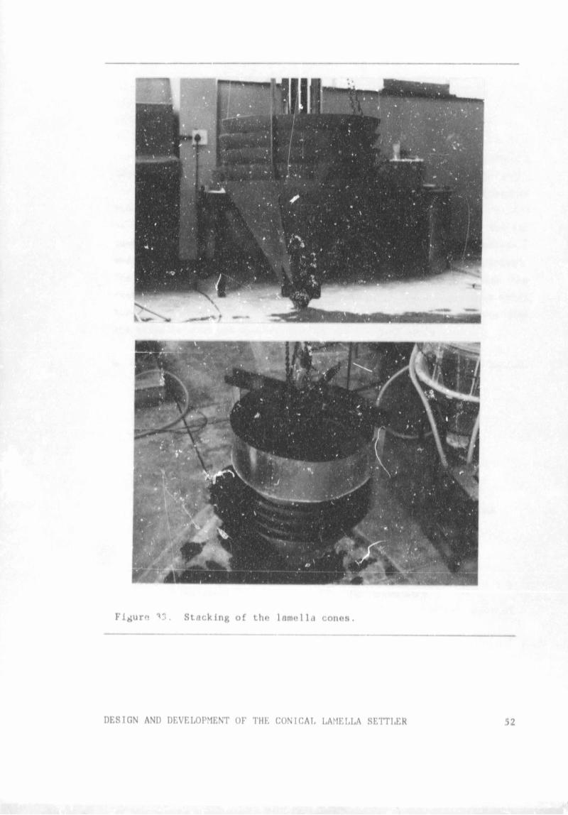
The above two photographs show the cones stacked on top of cach other and
in so doing they form the spacings through which the water is to flow from
the center to the periphery. The above figure also shows the stilling well
which consisted of a sheet plate around the edge of the upper cone. The
function of the stilling well is to prevent short circuiting that might
occur from the inside of the cones to the outside without first passing
through the plate spacings. This would be an important feature for cones
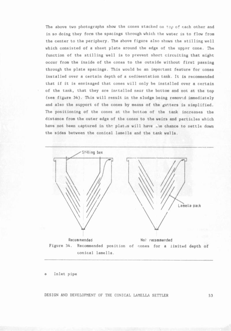
installed over a certain depth of a sedimentation tank. It is recommended
that if it is envisaged that cones will only be installed over a certain
of the tank, that they are installed near the bottom and not at the top
(see figure 34). This will result in the sludge being removed immediately
and also the support of the cones by means of the gutters is simplified.
The positioning of the cones at the bottom of the tank increases the
distance from the outer edge of the cones to the weirs and particles which
have not been captured in th" platjs will have chance to settle down
the sides between the conical lamella and the tank walls.
Recommendeo Nof recommended
Figure 34. Recommended position of cones for a limited depth of
conical lamella.
o Inlet pipe
DESIGN AND DEVELOPMENT OF THE CONICAL LAMELLA SETTLER 53
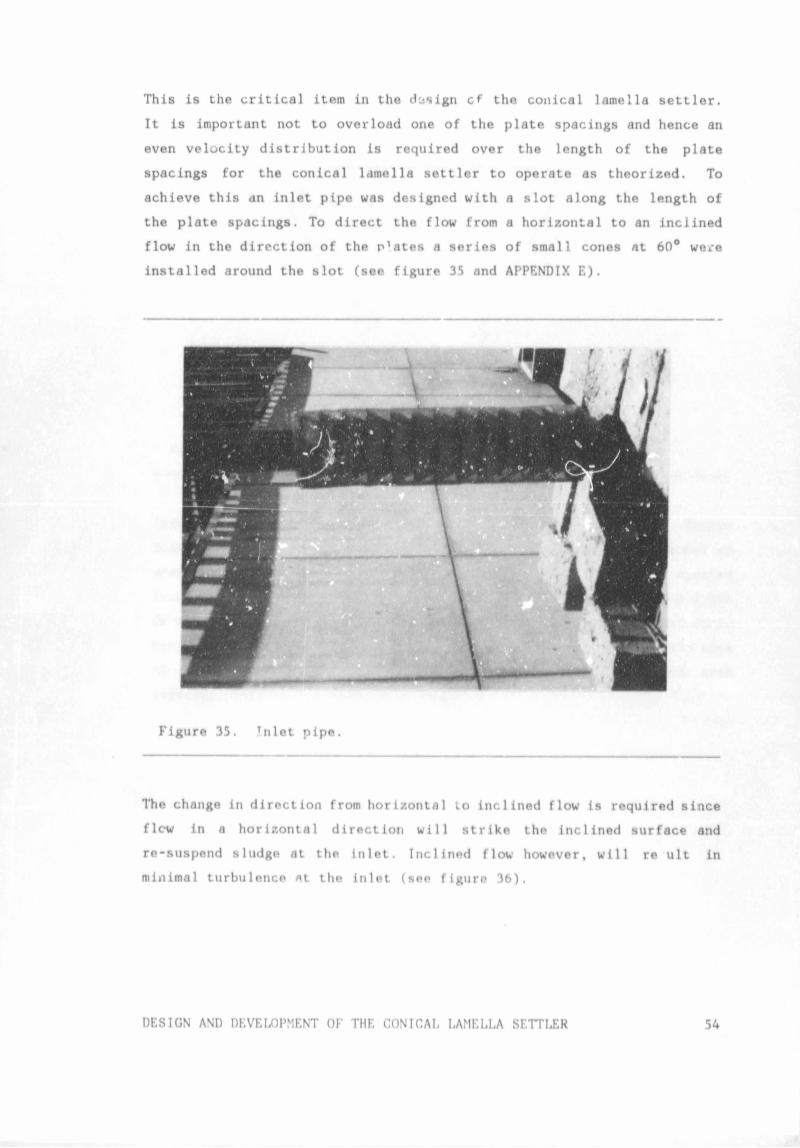
This is the critical item in the design cf the conical lamella settler.
It is important not to overload one of the plate spacings and hence an
even velocity distribution is required over the length of the plate
spacings for the conical lamella settler to operate as theorized. To
achieve this an inlet pipe was designed with a slot along the length of
the plate spacings. To direct the flow from a horizontal to an inclined
flow in the direction of the p’ates a series of small cones at 60° were
installed around the slot (see figure 35 and APPENDIX E).
Figure 35. !nlet pipe.
The change in direction from horizontal to inclined flow is required since
flew in a horizontal direction will strike the inclined surface and
re-suspend sludge at the inlet. Inclined flow however, will re ult in
minimal turbulence *t the inlet (see figure 36).
DESIGN AND DEVELOPMENT OF THE CONICAI, LAMELLA SETTLER 54
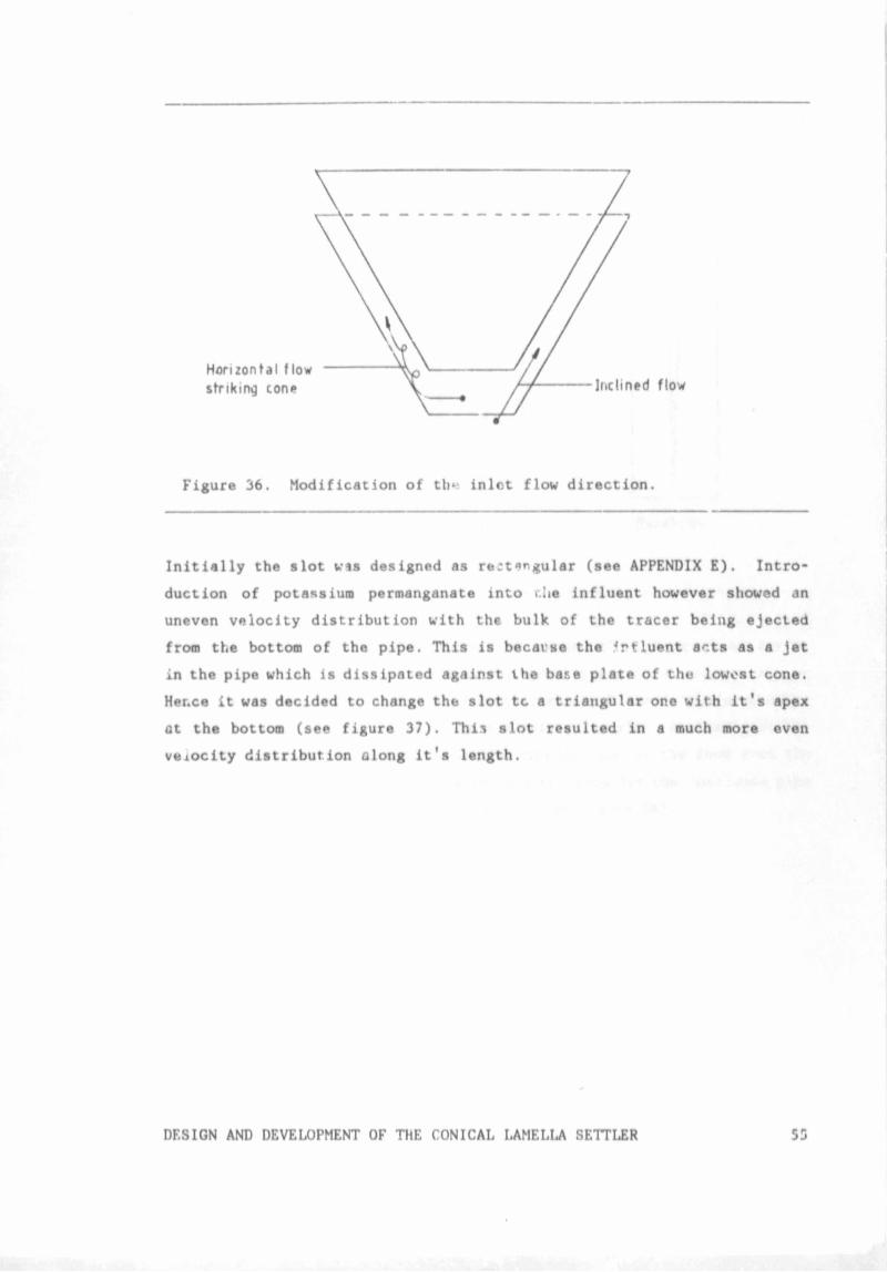
Figure 36. Modification of th« inlet flow direction.
Initially the slot wis designed as r«ct«rgular (see APPENDIX E). Intro*
duction of potassium permanganate into r.lie influent however showed an
uneven velocity distribution with the bulk of the tracer being ejected
from the bottom of the pipe. This is becai'se the 4rtiuent acts as a Jet
in the pipe which is dissipated against the base plate of the lowest cone.
Her.ce it was decided to change the slot tc a triangular one with it's apex
at the bottom (see figure 37). This slot resulted in a much more even
Vttiocity distribution along it's length.
DESIGN AND DEVELOPMENT OF ThE CONICAL LAMELLA SETTLER 55
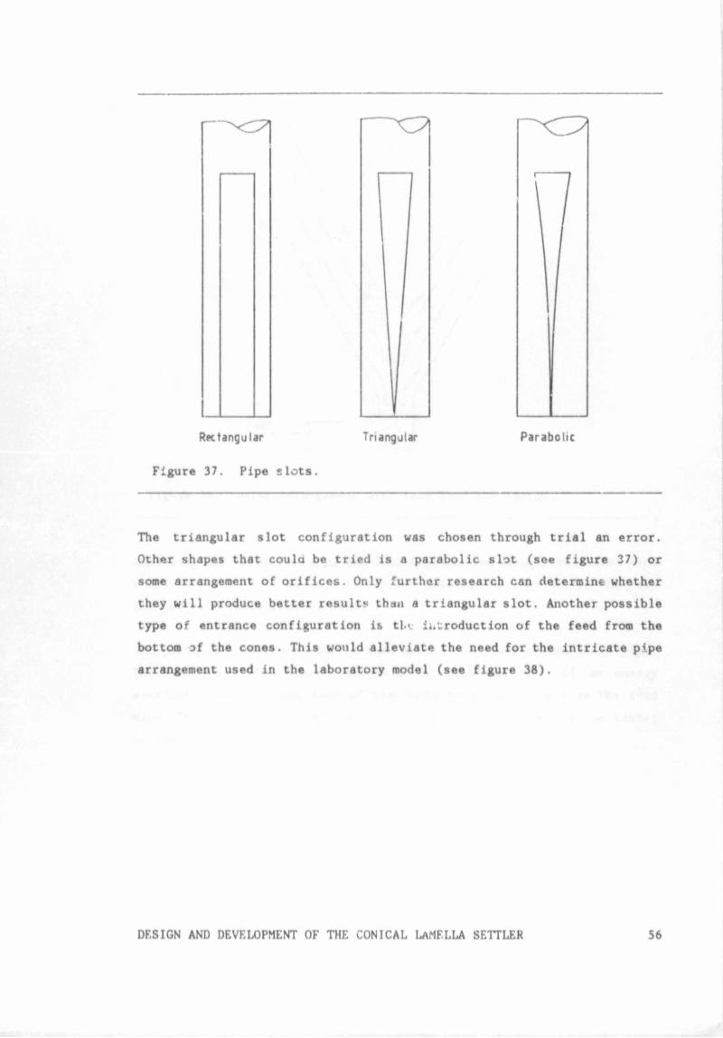
Rectangular Triangular Parabolic
Figure 37. Pipe slots.
The triangular slot configuration was chosen through trial an error.
Other shapes that coulci be tried is a parabolic slot (see figure 37) or
some arrangement of orifices. Only further research can determine whether
they will produce better result* than a triangular slot. Another possible
type of entrance configuration is tl>v introduction of the feed from the
bottom of the cones. This would alleviate the need for the intricate pipe
arrangement used in the laboratory model (see figure 38).
DESIGN AND DEVELOPMENT OF THE CONICAL La MFLLA SETTLER 56
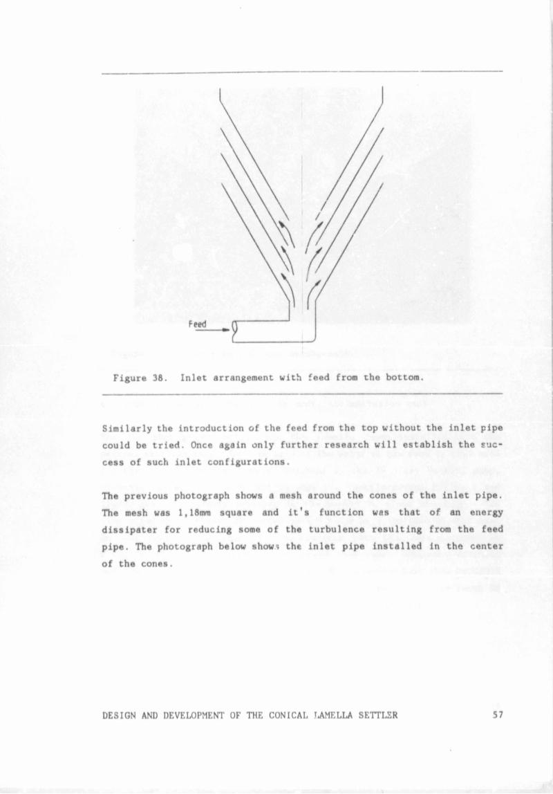
Figure 38. Inlet arrangement with feed from the bottom.
Similarly the introduction of the feed from the top without the inlet pipe
could be tried. Once again only further research will establish the suc
cess of such inlet configurations.
The previous photograph shows a mesh around the cones of the inlet pipe.
The mesh was 1,18mm square and it's function was that of an energy
dissipater for reducing some of the turbulence resulting from the feed
pipe. The photograph below show* the inlet pipe installed in the center
of the cones.
DESIGN AND DEVELOPMENT OF THE CONICAL LAMELLA SETTLER 57
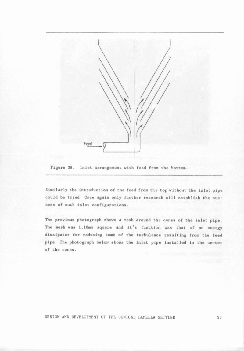
Figure 38. Inlet arrangement with feed from the bottom.
Similarly the introduction of the feed from thi top without the inlet pipe
could be tried. Once again only further research will establish the suc
cess of such inlet configurations.
The previous photograph shows a mesh around tha cones of the inlet pipe.
The mesh was 1,18mm square and it's function was that of an energy
dissipater for reducing some of the turbulencc resulting from the feed
pipe. The photograph below shows the inlet pipe installed in the center
of the cones.
DESIGN AND DEVELOPMENT OF THE CONICAL LAMELLA SETTLER 57
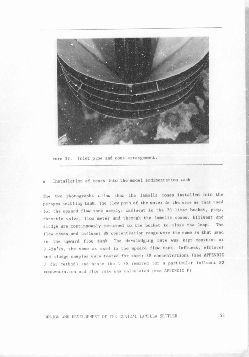
®,ure 39. Inlet pipe and cone arrangement.
o Installation of cones into the model sedimentation tank
The two photographs uc1ow show the lamella cones installed into the
perspex settling tank. The flow path of the water is the same as that used
for the upward flow tank namely: influent in the 70 liter bucket, pump,
throttle valve, flow meter and through the lamella cones. Effluent and
sludge are continuously returned to the bucket to close the loop. The
flow rates and influent SS concentration range were the same as that used
in the upward flow tank. The de-sludging rate was kept constant at
0 .45m’/s, the same as used in the upward flow tank. Influent, effluent
and sludge samples were tested for their SS concentrations (see APPENDIX
J for method) and hence the °0 SS removed for a particular influent SS
concentration and flow rate was calculated (see APPENDIX F).
DESIGN AND DEVELOPMENT OF THE CONICAL LAMELLA SETTLER58
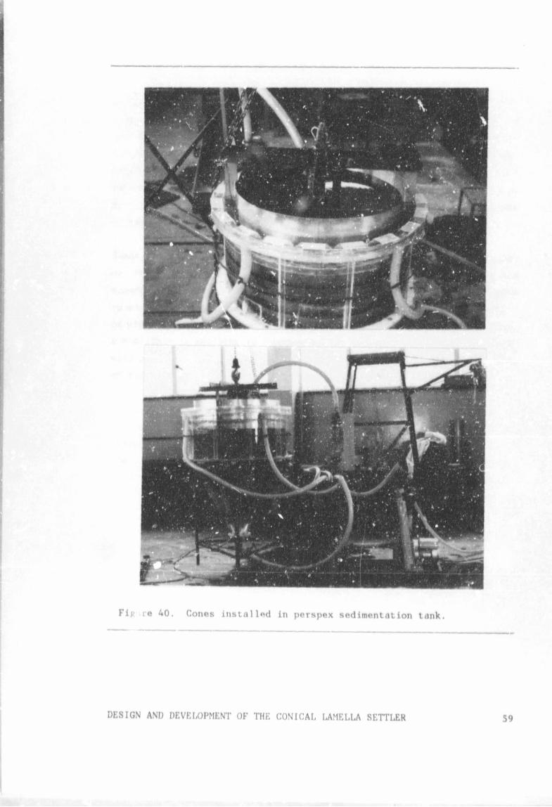
Fiv re 40. Cones installed in perspex sedimentation tank.
DESIGN AND DEVELOPMENT OF THE CONICAL LAMELLA SETTLER
Author Barthelme Sven-Helmut Name of thesis Up-rating Underground Sedimentation Tanks Subject To Hydraulic Overloading. 1987
PUBLISHER: University of the Witwatersrand, Johannesburg
©2013
LEGAL NOTICES:
Copyright Notice: All materials on the Un i ve r s i t y o f the Wi twa te r s rand , Johannesbu rg L ib ra ry website are protected by South African copyright law and may not be distributed, transmitted, displayed, or otherwise published in any format, without the prior written permission of the copyright owner.
Disclaimer and Terms of Use: Provided that you maintain all copyright and other notices contained therein, you may download material (one machine readable copy and one print copy per page) for your personal and/or educational non-commercial use only.
The University of the Witwatersrand, Johannesburg, is not responsible for any errors or omissions and excludes any and all liability for any errors in or omissions from the information on the Library website.