Embed Size (px)
Citation preview

® white paper
Using PCI Express® as the Primary System Interconnect in Multiroot Compute, Storage, Communications and Embedded SystemsBy Kwok Kong
OverviewWith the benefits of reduced power consumption, scalability of bandwidth, increased data throughput and improved signal integrity, PCI Express (PCIe®) has replaced legacy bus-based PCI and PCI-X, and become the de facto standard for on-board chip-to-chip connectivity. Due to legacy constructs in the bus-based standards it replaces (PCI and PCI-X), the system topologies of PCIe-based systems to date have been characterized by single root systems with PCIe providing connectivity to I/O and peripheral devices dedicated to that single processing complex.
Increasingly, with the move to bladed, multicard, chassis-based systems, designers and architects are seeking to leverage the high bandwidth, scalability, low power and system costs of PCIe interconnects to provide the primary system interconnect for multiroot and multiprocessor systems.
This white paper outlines key multiroot computing, storage and communications usage models with details on how PCIe can be employed as the primary system interconnect. Additionally, as redundancy for coherency and failover is common to many multiroot applications, a section on redundancy models for PCIe interconnect is offered.
IntroductionThree different types of devices exist in a native PCIe system—root complexes, PCIe switches and endpoints. Only one root complex exists in a PCIe tree. A root complex is a single processor sub-system that includes one PCIe port, one or more CPUs with associated RAM and memory controller, and other interconnect and/or bridging functions.
Historically, the most common usage model for PCIe is to connect a single root complex to dedicated I/O devices, such as networking controllers, Fibre Channel host bus adaptors, graphics controllers and other add-in cards in a desktop computer or stand-alone server. In this model, most traffic is sent from the CPU to an I/O device or from an I/O device to the CPU. There is very little peer-to-peer traffic between the I/O devices. This usage model and traffic pattern shall be referred to as I/O connectivity in this paper. Figure 1 illustrates an example I/O connectivity topology.
�
iDt® USIng PCI EXPRESS® AS THE PRIMARy SySTEM InTERCOnnECT In MUlTIROOT COMPUTE, STORAgE, COMMUnICATIOnS AnD EMbEDDED SySTEMS

�
iDt® USIng PCI EXPRESS® AS THE PRIMARy SySTEM InTERCOnnECT In MUlTIROOT COMPUTE, STORAgE, COMMUnICATIOnS AnD EMbEDDED SySTEMS
To take advantage of the high volume and low cost of PCIe technology, system vendors are beginning to use PCIe as the primary system interconnect in multiroot, multihost and embedded applications. In these applications, the PCIe interconnect provides the primary data and control plane connectivity between system blades, cards or sub-systems. The traffic pattern in this topology is primarily peer to peer in that any host or endpoint can send/receive traffic to/from any other host in the system. Further, systems demand that the interconnect provide deterministic latency and full line rate throughput for all transactions regardless of system configuration or loading. This usage model and traffic pattern is referred to as system interconnect in this paper.
Endpoint Endpoint Endpoint Endpoint
Endpoint
Root Complex
PCIeSwitch
UP: Upstream port
UP
UP
DP: Downstream port
PCIeSwitch
PCI-PCIBridge
PCI-PCIBridge
Virtual PCI Bus
PCI-PCIBridge
PCIe® Switch
DPDP
DPDP DP
DP
Figure 1. PCIe tree topology
An example of a PCIe-based multihost system topology is illustrated in Figure 2. The root complex processor at the top is the root complex for the system domain. The I/O blade is in the system domain and can only be configured by the root complex processor. Each endpoint processor is the root complex of its local domain. For those hosts that have the endpoint function built in, they can connect to the system interconnect PCIe switch directly. The endpoint function provides the isolation of address space between the local and the system domain. For other hosts, such as the x86-based CPU, an inter-domain PCIe switch is required to connect the x86 CPU to the system interconnect PCIe switch. An inter-domain PCIe switch provides a non-transparent bridge (nTb) port to isolate the address domains of the host from the rest of the system.

�
iDt® USIng PCI EXPRESS® AS THE PRIMARy SySTEM InTERCOnnECT In MUlTIROOT COMPUTE, STORAgE, COMMUnICATIOnS AnD EMbEDDED SySTEMS
PCIe Switch
EPProcessor
EPProcessor
RCProcessor
DP DP DP DP DP
PCIeSwitch
I/O
Processor
I/O I/O
EP Processor
System Domain
Local Domains
Local Domain
Dual GbEController
Dual GbEController
PCIeSwitch
GbE GbE GbE GbE
I/O Blade
PCIeSwitch
I/O
NB
x86 Processor
I/O I/O
EP Processor
PCIeInter-Domain
Switch
Figure 2. PCIe domains
This paper will detail system architectures using PCIe as the primary system interconnect for multiroot and multihost computing, storage and communication systems. As each of these applications benefit from or require redundancy, a section on implementation of PCIe-based redundant interconnect topologies is offered following the discussion of the application requirements.
Computing SystemsHigh-performance computing requires a high-bandwidth and low-latency system interconnect for interprocessor communication. Virtually all the latest x86-based CPUs, PowerPCs and embedded CPUs support PCIe. PCIe provides high bandwidth in the order of a few gbps to tens of gbps and low latency in the order of 200 nanoseconds, and provides a very cost-effective system interconnect solution for high-performance and cost-driven segments of the computing market.
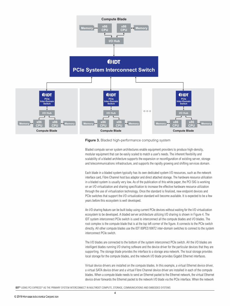
Bladed Computing SystemsAn example of a bladed high-performance computing system is shown in Figure 3. All the compute blades are interconnected using the IDT system interconnect PCIe switch. The compute blade at the top of the PCIe switch is the system root complex, and it connects directly to the PCIe switch. All other compute blades at the bottom of the PCIe switch use the IDT 89HPES16nT2 inter-domain PCIe switches to connect to the system interconnect switch. An inter-domain switch provides the nTb function to isolate the address domains of the local compute blade from the rest of the system. Memory address windows are created to allow each of the compute blades to directly access the memory of all the other compute blades. large blocks of data can be passed from one compute blade to all other compute blades with high throughput and low latency. In addition to direct access to the memory of other compute blades, the compute blades can communicate with each other using the nTb communication capability, such as the doorbell, message and scratchpad registers.
�
iDt® USIng PCI EXPRESS® AS THE PRIMARy SySTEM InTERCOnnECT In MUlTIROOT COMPUTE, STORAgE, COMMUnICATIOnS AnD EMbEDDED SySTEMS
Figure 3. Bladed high-performance computing system
bladed compute server system architectures enable equipment providers to produce high-density, modular equipment that can be easily scaled to match a user’s needs. The inherent flexibility and scalability of a bladed architecture supports the expansion or reconfiguration of existing server, storage and telecommunications infrastructure, and supports the rapidly growing and shifting services domain.
Each blade in a bladed system typically has its own dedicated system I/O resources, such as the network interface card, Fibre Channel host bus adaptor and direct attached storage. The hardware resource utilization in a bladed system is usually very low. As of the publication of this white paper, the PCI SIg is working on an I/O virtualization and sharing specification to increase the effective hardware resource utilization through the use of virtualization technology. Once the standard is finalized, new endpoint devices and PCIe switches that support the I/O virtualization standard will become available. It is expected to be a few years before this ecosystem is well developed.
An I/O sharing feature can be built today using current PCIe devices without waiting for the I/O virtualization ecosystem to be developed. A bladed server architecture utilizing I/O sharing is shown in Figure 4. The IDT system interconnect PCIe switch is used to interconnect all the compute blades and I/O blades. The root complex is the compute blade that is at the top left corner of the figure. It connects to the PCIe switch directly. All other compute blades use the IDT 89PES16nT2 inter-domain switches to connect to the system interconnect PCIe switch.
The I/O blades are connected to the bottom of the system interconnect PCIe switch. All the I/O blades are intelligent blades running I/O sharing software and the device driver for the particular devices that they are supporting. The storage blade provides the interface to a storage area network. The local storage provides local storage for the compute blades, and the network I/O blade provides gigabit Ethernet interfaces.
Virtual device drivers are installed on the compute blades. In this example, a virtual Ethernet device driver, a virtual SATA device driver and a virtual Fibre Channel device driver are installed in each of the compute blades. When a compute blade needs to send an Ethernet packet to the Ethernet network, the virtual Ethernet device driver forwards the Ethernet packet to the network I/O blade via the PCIe interface. When the network
MemoryMemory x86CPU
x86CPU
I/O Hub
Compute Blade
MemoryMemory
PCIeInter-Domain
Switch
x86CPU
x86CPU
I/O Hub
Compute Blade
MemoryMemory
PCIeInter-Domain
Switch
x86CPU
x86CPU
I/O Hub
Compute Blade
MemoryMemory
PCIeInter-Domain
Switch
x86CPU
x86CPU
I/O Hub
Compute Blade
PCIe System Interconnect Switch

�
iDt® USIng PCI EXPRESS® AS THE PRIMARy SySTEM InTERCOnnECT In MUlTIROOT COMPUTE, STORAgE, COMMUnICATIOnS AnD EMbEDDED SySTEMS
I/O blade receives the Ethernet packet, the Ethernet I/O sharing software examines the packet header and forwards the packet to the appropriate external gigabit Ethernet interface to reach the destination. When a reply is received by the network I/O blade from its gigabit Ethernet interface, the I/O sharing software examines the Ethernet packet header and forwards the packet to the destination compute blade. The gigabit Ethernet interfaces are shared by all the compute blades.
When a compute blade needs to access the local storage, the virtual SATA device driver forwards the request to the local storage blade. The local storage I/O sharing software makes a request to the local disk on behalf of the compute blade and the result is returned to the request compute blade. The local storage is shared by all the compute blades.
The same procedure applies to the storage blade. When a compute blade makes a request to access a remote disk via the Fibre Channel interface, the virtual Fibre Channel device driver forwards the request to the storage blade. The storage I/O sharing software forwards the request to the external Fibre Channel interface. When a response is received on the Fibre Channel interface, the response is forwarded by the storage I/O sharing software to the target compute blade.
Figure 4. I/O Sharing in a Bladed Computing System
atCa-Based Computing SystemsAdvanced Telecom Computing Architecture (ATCA) is a series of industry standard specifications for the next generation of carrier-grade communications equipment. PCIe is a standard defined for the backplane high-speed interconnect of the ATCA platform. ATCA provides standardized platform architecture for carrier-grade telecommunication applications. Embedded high-performance computing platforms have been built using the ATCA platform and using PCIe as the system interconnect.
Memory Memoryx86CPU
x86CPU
I/O Hub
Compute Blade
PCIeInter-Domain
Switch
Memory Memoryx86CPU
x86CPU
I/O Hub
Compute Blade
PCIeInter-Domain
Switch
MemoryMemory x86CPU
x86CPU
I/O Hub
Compute Blade
Processor
SATA/SAS Expander Dual GbEController
Dual GbEController
GbE GbE GbE GbE
Processor
Fibre ChannelController
FC FC
Storage Blade Local Storage NetworkI/O Blade
PCIe System Interconnect Switch
Processor

�
iDt® USIng PCI EXPRESS® AS THE PRIMARy SySTEM InTERCOnnECT In MUlTIROOT COMPUTE, STORAgE, COMMUnICATIOnS AnD EMbEDDED SySTEMS
An example of an embedded compute blade is shown in Figure 5. Up to eight Advanced Mezzanine Card (AMC) modules can be put onto an ATCA blade. In this example, eight AMC compute modules are on a single blade. An IDT system interconnect PCIe switch is used to interconnect all the AMC modules. The x86 CPU that connects to the top of the system interconnect PCIe switch is the root complex. An IDT 89PES16nT2 inter-domain PCIe switch is used to connect an x86-based AMC module to the system interconnect PCIe switch to isolate the local CPU’s address domain from the rest of the system. For those embedded CPUs, such as the Freescale MPC8548E, that have the PCIe endpoint function built in, they can connect directly to the system interconnect PCIe switch. A system designer can build a complete compute system on a blade with AMC modules.
PCIeInter-Domain
Switch
PCIeInter-Domain
Switch
Memory x86CPU
I/O Hub
Compute Blade
PCIe System Interconnect SwitchAMC
AMC
x86-basedAMC
x86-basedAMC
Figure 5. ATCA-based embedded computing
Storage SystemsLow-end to Midrange SystemsAn example of a low-end to midrange storage system is shown in Figure 6. This system connects to a storage area network via the host Fibre Channel interface. A gigabit Ethernet interface may be added to the system to provide network attached storage. It provides highly reliable and high throughput access to data. Disks may be added to increase the storage capability or bad disks can be swapped out dynamically when the system is up and running to provide a highly available storage system. Two processor controllers in the system provide mutual backup. both processor controllers have access to the local disks.
In an active/standby configuration, the active controller has full control over all the local disks and the standby controller does not access the disks at all. If there is a failure in the active controller, the standby controller becomes the active controller and has full control over all the local disks.
In an active/active configuration, both controllers are active. The disks are divided into two partitions with each controller controlling one partition. both controllers are actively serving requests from hosts. The overall system throughput is much higher compared to the active/standby configuration. If one controller fails, the other controller takes over the rest of the disk partition. The performance of the system degrades gracefully. The active/active configuration is a more common usage model in this application space.

�
iDt® USIng PCI EXPRESS® AS THE PRIMARy SySTEM InTERCOnnECT In MUlTIROOT COMPUTE, STORAgE, COMMUnICATIOnS AnD EMbEDDED SySTEMS
The non-transparent ports on the IDT 89PES24nT3 inter-domain PCIe switches are used to connect the two controllers. The controllers can communicate with each other using an nTb communication capability, such as the doorbell, message and scratchpad registers. Heartbeat and checkpoint messages are sent periodically from the active controller to the standby controller. The standby controller monitors the state of the active controller.
The non-transparent port connection is also used to maintain disk cache coherency. When the active controller receives a “disk write” request from a host, the data is stored in the disk cache memory and is written to the disks later to improve system performance. If the controller fails before the data is written from the disk cache memory to the disk, that data is lost. To avoid lost data, the disk cache is mirrored in the other controller. When a controller receives a “disk write” request from a host, the data is stored in the local disk cache memory and a copy of the data is also sent to the other controller’s disk cache memory as a backup.
PCIeInter-Domain
Switch
StorageCache
Memory
x86CPU
I/O Hub
Controller 1
JBOD
Fibre ChannelController
PCIeInter-Domain
Switch
StorageCache
Memory
x86CPU
I/O Hub
Controller 2
Fibre ChannelController
To Host
Cache Mantenance andPossible Data Flow
FC 2Gbpsand 4Gbps
FC 2Gbpsand 4Gbps
To Host
Figure 6. Low-end to midrange storage system
Midrange to high-end SystemsAn example of a midrange to high-end storage system is shown in Figure 7. Multiple storage controllers exist in such a system. All controllers are active and, at the same time, backing up other controllers. For example, controller 1 and controller 2 are working as an active/active pair, controller 3 and controller 4 are working as an active/active pair, and so on. Multiple Fibre Channel and iSCSI devices exist on the storage controller to provide the interfaces to the hosts. A Fibre Channel controller is used to interface to the local disk array via an internal Fibre Channel switch. Only one disk array is shown in this example, but more Fibre Channel controllers may be added to interface to multiple local disk arrays to scale up the storage capability. The number of storage controllers can be increased or decreased to match the requirements of the transaction load.
An IDT I/O connectivity PCIe switch is used on the storage controller to expand the number of PCIe ports. IDT provides multiple I/O connectivity PCIe switches to match port counts and bandwidth requirements. All the controllers are interconnected using an IDT system interconnect PCIe switch. The IDT 89PES16nT2 inter-domain PCIe switches are used to isolate the address domains of the storage controllers when the storage processors are x86-based CPUs. The controllers can communicate with each other using the nTb communication capability, such as doorbell, message and scratchpad registers.

�
iDt® USIng PCI EXPRESS® AS THE PRIMARy SySTEM InTERCOnnECT In MUlTIROOT COMPUTE, STORAgE, COMMUnICATIOnS AnD EMbEDDED SySTEMS
Figure 7. Midrange to high-end storage system
Communication SystemsLow-end Network routerPCIe may be used in low-end network routers to connect the CPU and network adapter cards (or line cards). The CPU performs packet forwarding, handles routing protocols to manage the routing table and runs management software to control the operation of the router. A router using an IDT PCIe switch is shown in Figure 8. A PCIe switch forwards transactions between the CPU’s local bus and the PCIe interface. Packets received by a network adapter card are usually transferred by direct memory access to the CPU’s memory subsystem using the PCIe interface. The CPU processes these packets and forwards them to the destination network adapter card using the PCIe interface.
line cards are initialized and configured by the packet processor engine during system startup. All packets received by a line card are sent to the packet processor engine, which handles all packet processing and forwarding decisions. Once the packet forwarding decision is made, the packet processor engine sends the packet to the destination line card, which transmits the packet to its network interface. The performance of the system is limited by the processing power of the packet processing engine.
PCIe can be used to build low-cost, high-performance, low-end network routers as well as midrange network routers. A low-end network router can support system bandwidths up to a few hundred Mbps. A midrange network router can support system bandwidths up to 10 gbps. Since traffic flows from/to the packet processor engine to/from the line cards, an I/O connectivity PCIe switch is used.
PCIe I/OContectivity
Switch
StorageCache
Memory
x86CPU
I/O Hub
Controller 1
Fibre ChannelController
iSCSIController
Fibre ChannelController
Hosts
PCIe I/OContectivity
Switch
StorageCache
Memory
x86CPU
I/O Hub
Controller n
Fibre ChannelController
iSCSIController
Fibre ChannelController
Hosts
Disk Array
PCIe Switch Module
Fibre ChannelController
PCIeInter-Domain
Switch
PCIeInter-Domain
Switch
PCIe System Interconnect Switch

�
iDt® USIng PCI EXPRESS® AS THE PRIMARy SySTEM InTERCOnnECT In MUlTIROOT COMPUTE, STORAgE, COMMUnICATIOnS AnD EMbEDDED SySTEMS
FramerPHY
NetworkController
FramerPHY
NetworkController
MemoryMemory CPU CPU
I/O Hub
Package Processor Engine
PCIe I/O Connectivity Switch
FramerPHY
NetworkController
Figure 8. Low-End Network Router
Midrange to high-end Network routerA midrange to high-end network router can be built using the system interconnect PCIe switch. A high-end network router can support system bandwidth up to around 100 gbps. An example of a network router is shown in Figure 9. In this architecture, the root complex is the route processor engine. It handle the control plane traffic, such as the routing protocols, to manage the routing table and runs management software to control the operation of the router. The packet processing and forwarding functions are distributed to the line cards. All line cards are intelligent and have packet processing engines. Most embedded processors have PCIe endpoint function support and can be connected to the system interconnect PCIe switch directly. When a x86 CPU is used as the packet processing engine, the IDT 89PES16nT2 inter-domain switch is needed to connect the x86 CPU to the system interconnect PCIe switch.
When a packet is received by a line card, the local packet processing engine processes the packet and forwards the data plane packet to the destination line card directly. The route processor engine is not involved in the packet forwarding. All line cards can forward packets to all other line cards concurrently and autonomously. The processing power of the packet processing engine is required only to handle the bandwidth of the line card where the packet processing engine is resident. This allows the system bandwidth to scale up or down depending on the line card interface bandwidth requirement.
The diagram only shows a single PCIe interface to carry the control and data plane traffic. Optionally, users may physically split the control and data plane traffic using separate paths. Two PCIe switches are required in this model — one to carry the control plane traffic and the other to carry the data plane traffic.

�0
iDt® USIng PCI EXPRESS® AS THE PRIMARy SySTEM InTERCOnnECT In MUlTIROOT COMPUTE, STORAgE, COMMUnICATIOnS AnD EMbEDDED SySTEMS
x86CPU
NetworkController
FramerPHY
NetworkController
EmbeddedCPU
FramerPHY
MemoryMemory CPU CPU
I/O Hub
Route Processor Engine
PCIe System Innterconnect Switch
x86CPU
NetworkController
FramerPHY
PCIeInter-Domain
Switch
PCIeInter-Domain
Switch
Figure 9. Midrange to high-end network switch
RedundancyA highly available and reliable application generally requires some level of redundancy. A dual root complexes topology has an active and a standby root complex. An example of this dual root complexes topology is shown in Figure 10. An IDT system interconnect PCIe switch, such as the 89HPES64H16, supports the redundant upstream port feature. The root complex that is connected to the active upstream port of the PCIe switch is the active root complex, and the one that is connected to the redundant upstream port is the standby root complex. During normal operation, the active root complex is in control of the system and is the root complex of the system domain. The standby root complex has no connection to the system domain. An out-of-band connection (not shown) between the active and standby root complexes is present to allow monitoring between active and standby. Heartbeat and checkpoint messages are sent periodically from the active root complex to the standby root complex. The standby root complex monitors the state of the active root complex.

��
iDt® USIng PCI EXPRESS® AS THE PRIMARy SySTEM InTERCOnnECT In MUlTIROOT COMPUTE, STORAgE, COMMUnICATIOnS AnD EMbEDDED SySTEMS
The standby root complex takes over as the active root complex when a managed switchover is requested or the standby root complex detects a failure in the active root complex. A managed switchover is initiated by the user for scheduled maintenance or software upgrades, or in response to some form of demerit checking within the active root complex.
The standby root complex monitors the state of the active root complex through heart beat and checkpoint messages. When the standby root complex detects a failure in the active root complex, the standby root complex configures the IDT system interconnect PCIe switch to switchover. After switchover, the standby root complex becomes the active root complex.
The IDT 89PES64H16 PCIe switch supports the watchdog-timer-initiated failover feature. When the active root complex has not reset the watchdog timer within a certain time period (as configured during initialization), the PCIe switch failovers to its redundant upstream port. This is expected to happen if there is some sort of hardware or major software failure in the active root complex. The standby root complex takes over as the active root complex. This is an alternative method of initiating the failover.
Figure 10. Dual root complexes redundancy
The switch is still a single point of failure in the dual root complexes topology. For a fully redundant system, a dual-star topology may be deployed, as shown in Figure 11. In this topology, a standby root complex and a system interconnect PCIe switch are added to provide switch redundancy. The IDT 89PES24nT3 inter-domain PCIe switch is added to the compute blade. Each compute blade connects to two system interconnect PCIe switches, but only one of the two connections is active. The 89PES24nT3 inter-domain switch supports nTb on one of its ports. In this topology, the port that has the standby connection is in non-transparent mode. The upstream port of the IDT 89PES24nT3 inter-domain switch connects to the downstream port of the system interconnect PCIe switch. During normal operation, all compute blades connect to the active root complex. The active root complex is in control of the system. An out-of-band connection (not shown) exists between the active and standby root complexes. Heartbeat and checkpoint messages are sent periodically from the active root complex to the standby root complex. The standby root complex monitors the state of the active root complex.
MemoryMemory x86CPU
x86CPU
I/O Hub
Active Root Complex
MemoryMemory x86CPU
x86CPU
I/O Hub
Standby Root Complex
MemoryMemory
PCIeInter-Domain
Switch
x86CPU
x86CPU
I/O Hub
Compute Blade
MemoryMemory
PCIeInter-Domain
Switch
x86CPU
x86CPU
I/O Hub
Compute Blade
MemoryMemory
PCIeInter-Domain
Switch
x86CPU
x86CPU
I/O Hub
Compute Blade
PCIe System Interconnect Switch

��
iDt® USIng PCI EXPRESS® AS THE PRIMARy SySTEM InTERCOnnECT In MUlTIROOT COMPUTE, STORAgE, COMMUnICATIOnS AnD EMbEDDED SySTEMS
When the standby root complex detects a failure in the active root complex, the standby root complex configures the IDT inter-domain PCIe switches, which are on the compute blades, to switchover. During the switchover, the upstream port and the nTb port of the IDT 89PES24nT3 inter-domain switch are swapped. The upstream port becomes the nTb port and the nTb port becomes the upstream port. After switchover, the standby root complex becomes the active root complex.
The IDT 89PES24nT3 switch supports the watchdog-timer-initiated failover feature. When the active root complex has not reset the watchdog timer within a certain time period (as configured during initialization), the PCIe switch swaps its upstream port with its non-transparent bridge port. If there is a failure in the active root complex, the watchdog timer expires and triggers the port swapping; hence, the failover. The standby root complex takes over as the active root complex. This is an alternative method of initiating the failover.
Figure 11. Dual-star redundancy
ConclusionPCIe has become the de facto chip-to-chip interconnect and has been historically used to connect a single root complex to associated I/O and peripheral devices as exemplified by desktop computing and stand-alone (rack, motherboard-based and so on) servers. Increasingly, with the move to bladed, multicard, chassis-based systems, designers and architects are seeking to leverage the high bandwidth, scalability, low power and low system costs of PCIe interconnects to provide the primary system interconnect for multiroot and multiprocessor systems.
IDT provides I/O connectivity, system interconnect and inter-domain PCIe switches. The IDT PCIe switch solution delivers the performance, optimal resource utilization, scalability, remote access service and security features that are essential for the successful design and deployment of systems that have been described in this paper. The solution presented in this white paper was designed with the needs of leading bladed multihost, storage and communication system manufacturers in mind, since it is architected to scale with their performance and capability needs well into the future.
MemoryMemory
PCIeInter-Domain
Switch
x86CPU
x86CPU
I/O Hub
Compute Blade
PCIeInter-Domain
Switch
MemoryMemory
PCIeInter-Domain
Switch
x86CPU
x86CPU
I/O Hub
Compute Blade
PCIeInter-Domain
Switch
MemoryMemory
PCIeInter-Domain
Switch
x86CPU
x86CPU
I/O Hub
Compute Blade
PCIeInter-Domain
Switch
MemoryMemory x86CPU
x86CPU
I/O Hub
Active Root Complex
PCIe System Interconnect Switch
MemoryMemory x86CPU
x86CPU
I/O Hub
Standby Root Complex
PCIe System Interconnect Switch

ReferencesPCI Express base specification Revision 1.1PCI Express base specification Revision 2.0IDT 89HPES24nT3 PCI Express® Switch User ManualIDT 89HPES16nT2 PCI Express® Switch User ManualIDT 89HPES64H16 PCI Express® Switch User ManualMPC8548E PowerQUICC III Integrated Processor Family Reference ManualIDT Application note An-571: PCI Express® System Interconnect Software Architecture for x86-based Systems
GlossaryaMC Advanced Mezzanine Card
atCa Advanced Telecom Computing Architecture
CpU Central processing unit
Dp Downstream port
ep Endpoint
Gb/s gigabits per second
Gbps gigabits per second
i/O Input/output
iSCSi SCSI protocol over TCP/IP
JBOD Just a bunch of disks
Mbps Megabits per second
NB north bridge
NtB non-transparent bridge
pCie PCI Express
phY Physical layer of open system interconnection model
raM Random access memory
rC Root complex
SaS Serial-Attached SCSI
Sata Serial Advanced Technology Attachment
SiG Special interest group
Up Upstream port
®
© 2008 Integrated Device Technology, Inc. All rights reserved. Product specifications subject to change without notice. IDT and the IDT logo are registered trademarks of Integrated Device Technology, Inc. All other brands, product names and marks are or may be trademarks or registered trademarks used to identify products or services of their respective owners. Printed in USA 7-08/MC/BWD/PDF
WP-PCIeMROOT-078
Discover what IDT know-how can do for you.
www.IDT.com/go/PCIeFor Sales click on the support tab on iDt.com800 345 7015 within USA +408 284 8200 worldwide Fax: +408 284 2775
For tech Support:[email protected] +408 284 8208 worldwide

Corporate HeadquartersTOYOSU FORESIA, 3-2-24 Toyosu,Koto-ku, Tokyo 135-0061, Japanwww.renesas.com
Contact InformationFor further information on a product, technology, the most up-to-date version of a document, or your nearest sales office, please visit:www.renesas.com/contact/
TrademarksRenesas and the Renesas logo are trademarks of Renesas Electronics Corporation. All trademarks and registered trademarks are the property of their respective owners.
IMPORTANT NOTICE AND DISCLAIMER
RENESAS ELECTRONICS CORPORATION AND ITS SUBSIDIARIES (“RENESAS”) PROVIDES TECHNICAL SPECIFICATIONS AND RELIABILITY DATA (INCLUDING DATASHEETS), DESIGN RESOURCES (INCLUDING REFERENCE DESIGNS), APPLICATION OR OTHER DESIGN ADVICE, WEB TOOLS, SAFETY INFORMATION, AND OTHER RESOURCES “AS IS” AND WITH ALL FAULTS, AND DISCLAIMS ALL WARRANTIES, EXPRESS OR IMPLIED, INCLUDING, WITHOUT LIMITATION, ANY IMPLIED WARRANTIES OF MERCHANTABILITY, FITNESS FOR A PARTICULAR PURPOSE, OR NON-INFRINGEMENT OF THIRD PARTY INTELLECTUAL PROPERTY RIGHTS.
These resources are intended for developers skilled in the art designing with Renesas products. You are solely responsible for (1) selecting the appropriate products for your application, (2) designing, validating, and testing your application, and (3) ensuring your application meets applicable standards, and any other safety, security, or other requirements. These resources are subject to change without notice. Renesas grants you permission to use these resources only for development of an application that uses Renesas products. Other reproduction or use of these resources is strictly prohibited. No license is granted to any other Renesas intellectual property or to any third party intellectual property. Renesas disclaims responsibility for, and you will fully indemnify Renesas and its representatives against, any claims, damages, costs, losses, or liabilities arising out of your use of these resources. Renesas' products are provided only subject to Renesas' Terms and Conditions of Sale or other applicable terms agreed to in writing. No use of any Renesas resources expands or otherwise alters any applicable warranties or warranty disclaimers for these products.
(Rev.1.0 Mar 2020)
© 2020 Renesas Electronics Corporation. All rights reserved.