Embed Size (px)
Citation preview

8/15/2019 C-0024_TLZ-THLZ_04-08
http://slidepdf.com/reader/full/c-0024tlz-thlz04-08 1/46

8/15/2019 C-0024_TLZ-THLZ_04-08
http://slidepdf.com/reader/full/c-0024tlz-thlz04-08 2/46
1
Radial Fans
Page
General information of the series TLZ, THLZ 2-8
1.
2.
3.
Fan Construction
Fan Accessories
Motor Selection
2
6
8
4.
4.1
4.2
4.3
4.3.14.3.2
Technical lnformation
General
Information on Sound Power Levels
Explanation of Performance Curves
Example of selection for TLZExample of selection for THLZ
9-12
9
9
10
1112
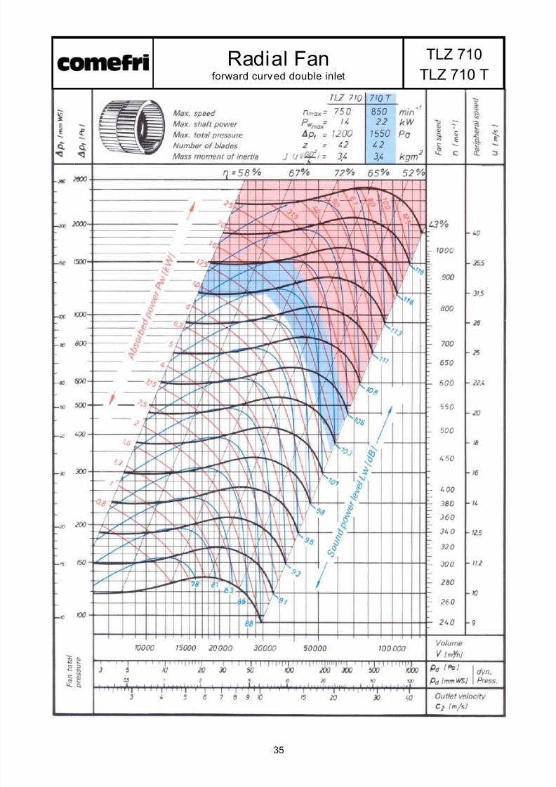
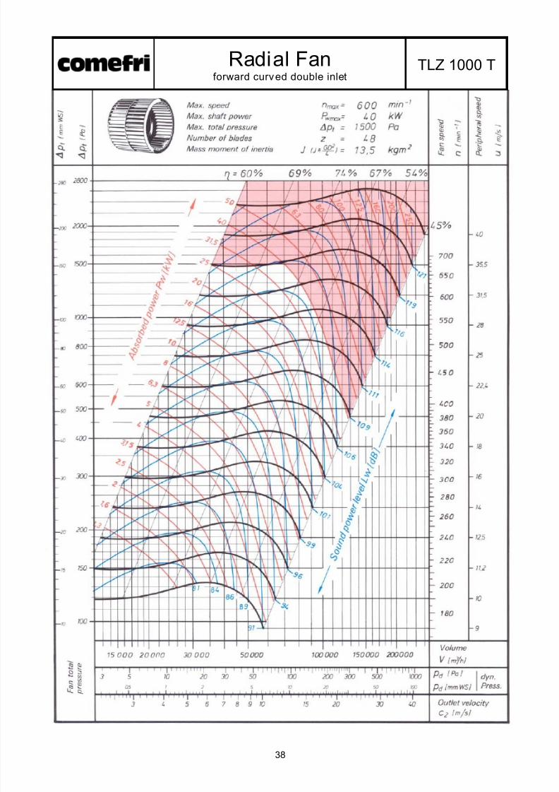
5. Performance Curves 13-38
6.
6.1
6.2
6.3
6.46.5
Dimensions and Weights
Dimensions TLZ 160 ÷ 710, TLZ 200 R ÷ 710 R
Dimensions TLZ 710 T ÷ 1000 T
Dimensions THLZ 180 ÷ 450, THLZ 200 R ÷ 450 R
Dimensions of Fan Side PlatesWeights of Fans
39
40
41
4242
7. Fan Discharge Positions and Accessories 43
8. Example for Ordering 44
Note:
This catalogue has to be used only for pre-selections. A detailed selection isavailable from our AEOLUS PLUS selection program

8/15/2019 C-0024_TLZ-THLZ_04-08
http://slidepdf.com/reader/full/c-0024tlz-thlz04-08 3/46
2
Radial Fans
have been designed specially for ventilation and air conditioning units. They of-fer the following advantages to the unit manufacturer:
compact design for space saving installationshigh efficiency operation for economic running costslow operational noise levels and vibratation free runningwide volume range and high pressure development
designed for flexible applications and temperature range of -30°C to +80°Cfans TLZ THLZ all dimensionally interchangeablestandardized components sized in accordance with R20 DIN 323superb qualityshort delivery from stock warehousesprices to meet your budget
COMEFRI double inlet fans are available in the following range with dimensio-nally identical casings
Pic 1
Type TLZ
High capacity and efficiency
Fan with forward curved impeller
Pic 2
Type THLZ
High capacity and efficiency
Fan with backward curved impeller
Forward and backward curved fans are engineered to identical dimensions forinterchangeability.Fan inlet diameters are the same, as impeller diameter. Although the fans have the same external dimensions size to size, their perfor-mance curves vary significantly due to the different impeller design.
1. Fan Construction
1.1 Casings
All fan casings to size 1000 are manufactured from high quality galvanizedsteel.
Pic 3
System of locking side
plates to scroll by
«Pittsburgh» seam
Series TLZ size 160 up to 400 and THLZ 180 to 400
The casings are manufactured with Pittsburgh seams as described above.This system gives great strength as well as ensuring leak proof joins. Predrilledholes are located in the side plates to take either feet or frames as accessories.These are supplied extra.

8/15/2019 C-0024_TLZ-THLZ_04-08
http://slidepdf.com/reader/full/c-0024tlz-thlz04-08 4/46
3
Pic 4Fan casing of Fan typesTLZ 450 to 710 and THLZ 450
Series TLZ 450 to 710 and THLZ size 450
All casings are manufactured with Pittsburgh seams as described above andon the inside of the side plates nuts are applied enabling easy fixing of feetor frames by standard metric bolts, supplied as extra.
Pic 5Fan casing of Fan Type TLZ.The series T bearing arrangement is shownnecessitating the frame to be supplied at anintegraI part of the unit.
Serie TLZ size 710 to 1000
Fans are supplied with integral bearing frames and cast iron plummer blockbearings housings.
1.2 Fan Inlets
To ensure high efficiency, fans are supplied with aerodynamically shapedfan inlets. These nozzles form part of the side casing on the TLZ fans.On fan series THLZ, the inlet cones are separate pieces, bolted to the sideplate.
1.3 Impellers
COMEFRI high efficiency impellers are specially designed to give high volu-me and pressures whilst maintaining smooth vibration free running. Even at
high peripheral speeds the fans are stable. Fan impellers are statically anddynamically balanced, in accordance with VDI 2060 and ISO 1940/1, grade G6,3. Impeller diameters are in series R20 according to DIN 323.

8/15/2019 C-0024_TLZ-THLZ_04-08
http://slidepdf.com/reader/full/c-0024tlz-thlz04-08 5/46
4
Pic 6High efficiency impeller with forward curvedimpellers type TLZ.
COMEFRI Fan series TLZ
These fans are supplied with forward curved impellers manufactured in galva-nized sheet steel. The impellers are designed for maximum efficiency to latesttechnology. Impeller blades are mounted on to a common backplate and loc-ked onto a holding shroud. A substantial aluminium hub is rigidly connected tothe backplate and precision machined to receive the fan shaft.
Pic 7High efficiency impeller with backward curvedblades type THLZ.
COMEFRI Fan series THLZ
These fans are supplied with high efficiency non-overloading impellers havingbackward curved blades. The blade shape results from research at our testlaboratory and is specially designed to give high volume and pressurecharacteristics at high efficiency. Impellers sizes 180 to 450 are manufacturedin glass reinforced polyamid whereas fans above this size are made from highquality mild steel. These impellers are of welded construction and painted.
1.4 Shafts
Shafts are manufactured from high quality steel, keywayed at both ends andat the impeller location point.
1.5 Bearings
All fans are supplied as standard with pre-greased sealed-for-life ball bearings.These are always inspected prior to assembly to ensure quiet running. Bearingshave an L10 life of 20,000 HRS at peak performance. Limiting values for speedand power are indicated on the characteristic curves and should not beexceeded. Pulleys should be mounted close to the fan bearing. The variousbearing types are described as follows.

8/15/2019 C-0024_TLZ-THLZ_04-08
http://slidepdf.com/reader/full/c-0024tlz-thlz04-08 6/46
5
Pic 8Bearings of Radial Fans series TLZ size 160 upto 710.
Series TLZ size 160 to 710
Sealed-for-life bearings are located in formed support arms made from gal-vanised steel. The bearing race is mounted in a unique rubber anti-vibrationhousing which provides for sound insulation and smooth running (Pic 8).
Pic 9Bearings of Radial Fans seriesTHLZ size 180 to 450.
Series THLZ size 180 to 450
Bearings are similar to TLZ and are located with clamp collars (Pic 9).
Pic 10Bearing of Fan series TLZ 710 T to 1000 T.
Series TLZ 710 T to 1000 T
Plummer blacks containing self aligning ball journals are used in this range.The bearing being mounted onto the substantial fan frame (Pic 10).

8/15/2019 C-0024_TLZ-THLZ_04-08
http://slidepdf.com/reader/full/c-0024tlz-thlz04-08 7/46
6
2. Accessories
All fan can be supplied with the following accessories:
Pic 11Radial Fan Type THLZ 450 with feet.
2.1 Feet ...F
Manufactured from galvanized sheet steel. The predrilled fan feet are suppliedseparately with necessary fixing screws. Feet are available from fan size 160 to710.
Pic 12Radial Fan Type TLZ 500 with outlet flangeand frame.
2.2 Out let Flanges ...A
On TLZ fans to size 710 the outlet flanges can be supplied separately or fitted
to customer requirement. They are manufactured from galvanized steel anddrilled as the dimension sheets.
2.3 Fan Mounting Frames ...R
From size 200 to 710, separate fan frames are available as an alternativemethod of mounting.
Pic 13Radial Fan Type THLZ 225 complete withoutlet flange, inspection door and condensa-tion drain.
2.4 Inspection door
Can be fitted to the fan casing and consist in a galvanized steel plate fixedby quick release screws. Gaskets prevent leakage. For inspection door posi-tions see section 7 and 8.
2.5 Drain Plugs
Can be fitted at lowest point of the fan casing to drain condensation. Plugs are3/8" gas thread and can be located in positions described in section 7 and 8.
Accessory ordering should always indicate the position required as detailedin 7.2.

8/15/2019 C-0024_TLZ-THLZ_04-08
http://slidepdf.com/reader/full/c-0024tlz-thlz04-08 8/46
7
2.6 Anti -spark features
When selecting and installing fans for hazardous applications the relevant stan-dards must be considered as sparking can occur from the following conditions:- Contact sparking- Heat build-up- Build-up of electro-staticConsideration should also be given to the following:
Zone o:
fans are not suitable for this application.
Zone 1 :(Sub group G1-G3). Selection of fans in this category should take into conside-ration the following:- the max fan speed should be reduced by 20%- the max shaft power should be reduced by 30%- fans should only be selected for applications where the shaft is hori-zontal- guards should have a mesh size of no more than 12 mm.- design life of bearings at duty point should be 40000 hours minimum- driving ropes of the anti-static type should only be used
Zone 2:standard fans described in this catalogue are suitable.
To avoid sparking the following combinations of materials can be used:- steel with copper or brass- stainless steel with stainless steel
2.7 Inlet vane control
Pic 14Inlet vane control.
Volume regulation can be achieved by using the COMEFRI inlet vane control,see fig.14 and 15. This energy saving device can be supplied as an integralpart of THLZ fans from size 315. A special selection chart is available which isfor use with standard performance charts.The vane controller comprises a set of adjustable radial vanes mounted insidethe inlet nozzle. The vanes when set to the required angle regulate the volumewhilst directing the air into the impeller blade. The result is a considerable sa-ving in motor power. All moving components are located inside the fan withlinkage to the outside to facilitate the adjustment of the control by either electricor pneumatic actuator.
Pic 15Inlet vane control fitted to fan THLZ 450 R.

8/15/2019 C-0024_TLZ-THLZ_04-08
http://slidepdf.com/reader/full/c-0024tlz-thlz04-08 9/46
8
3. Motor Selection
The following safety margins should be added to the power requirements at thefan shaft as shown by the performance curves.
Rating TLZ THLZ
up to 10 kWover 10 kW
20%12%
15%12%
This safety margin compensate for transmission losses of the V-belt drive andfor possible minor inaccuracies in the calculation of the system resistance.When selecting the suitable motor special attention should be paid to the factthat if the acceleration time of the fan is longer than the maximum accelerationtime of the motor the trip time of the motor starter overload must be increasedor a larger motor or starter for heavy duty starting must be used.The acceleration time can be calculated from:a) in case of direct starting:
J n2
ta ≈ 1,5 10-5 PM
Where :
ta [s] - acceleration time
G D2
J [kgm2] - mass moment of inertia, J = m r
2 (≈
4)
n [min-1
] - nomimal speed of the fan
PM
[kW] - motor rating
b) in case of λ / ∆ starting, the acceleration time compared with direct starting is5.5 times Ionger .

8/15/2019 C-0024_TLZ-THLZ_04-08
http://slidepdf.com/reader/full/c-0024tlz-thlz04-08 10/46
9
4. Technical Explanations
4.1 GeneralThe formulae, signs and SI-units used in this catalogue correspond to the stan-dards DIN 1301, DIN 1345, DIN 45635 and to the Eurovent-Recommendations0/1 and1/1.Standard operating conditions for the fan performance curves:
air = 1.2 kg/m3
(at 1013 mbar and 293 K ( = 20°C))
4.2 Sound LevelsThe measurement of noise levels are taken according to DIN 45635. For thispurpose a harmonic analyzer type 2107 and Herz-Octave Band Filter type 1615of Messrs. Brüel + Kjaer are used. These precision measuring instrumentscomply with DIN 45633. The sound power level LW, referred to WO = 10
-12 watt,
required for calculation and design of sound absorbing units is marked in theperformance curves.
LW - Total Sound Power Level [dB]
LW* - Sound Power Level at a specific Octave Band Mid-Frequency [dB]
LP - Sound Pressure Level (non-weighted) [dB]
LP* - Sound Pressure Level at a specific Octave Band Mid-Frequency [dB]
LPA - Sound Pressure Level (weighted) [dB(A)]
f m - Octave Band Mid-Frequency [Hz]
L - Difference between the Total Sound Power Level LW and the non-weighted Sound Pressure Level LP [dB]
LW - Difference between the Total Sound Power Level LW and themeasured value at the corresponding Octave Band Mid-Frequency
[dB]
L A - Difference between the Total Sound Power Level LW and theweighted Sound Pressure Level LPA [dB]
The Sound Data of the fans is determined as follows:
1. The Total Sound Power Level can be ascertained from the Performance Cur-ves.
2. The Sound Power Level LW* at the different Octave Band Mid-Frequencies isdetermined from following equation:
LW* = LW - LW
The values for LW are given in Table 1.
Table 1:
Octave BandMid-Frequency f m Hz
63 125 250 500 1000 2000 4000 8000
L
W [dB] for TLZ
6 7 10 12 13 15 19 23
LW [dB] for THLZ 4 6 7 9 11 15 19 23
8/15/2019 C-0024_TLZ-THLZ_04-08
http://slidepdf.com/reader/full/c-0024tlz-thlz04-08 11/46
10
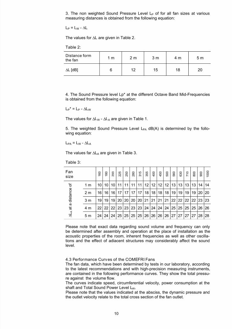
3. The non weighted Sound Pressure Level LP of for all fan sizes at variousmeasuring distances is obtained from the following equation:
LP = LW - L
The values for L are given in Table 2.
Table 2:
Distance formthe fan 1 m 2 m 3 m 4 m 5 m
L [dB] 6 12 15 18 20
4. The Sound Pressure level Lp* at the different Octave Band Mid-Frequenciesis obtained from the following equation:
LP* = LP - LW
The values for LW - L A are given in Table 1.
5. The weighted Sound Pressure Level LPA dB(A) is determined by the follo-wing equation:
LPA = LW - L A
The values far L A are given in Table 3.
Table 3:
Fansize 1
6 0
1 8 0
2 0 0
2 2 5
2 5 0
2 8 0
3 1 5
3 5 5
4 0 0
4 5 0
5 0 0
5 6 0
6 3 0
7 1 0
8 0 0
9 0 0
1 0 0
0
1 m 10 10 10 11 11 11 11 12 12 12 12 13 13 13 13 14 14
2 m 16 16 16 17 17 17 17 18 18 18 18 19 19 19 19 20 20
3 m 19 19 19 20 20 20 20 21 21 21 21 22 22 22 22 23 23
4 m 22 22 22 23 23 23 23 24 24 24 24 25 25 25 25 26 26
L A
a t a d i s t a n c e o f
5 m 24 24 24 25 25 25 25 26 26 26 26 27 27 27 27 28 28
Please note that exact data regarding sound volume and frequency can only
be determined after assembly and operation at the place of installation as theacoustic properties of the room, inherent frequencies as well as other oscilla-tions and the effect of adiacent structures may considerably affect the soundlevel.
4.3 Performance Curves of the COMEFRI FansThe fan data, which have been determined by tests in our laboratory, accordingto the latest recommendations and with high-precision measuring instruments,are contained in the following performance curves. They show the total pressu-re against the volume flow.The curves indicate speed, circumferential velocity, power consumption at the
shaft and Total Sound Power Level LW.Please note that the values indicated at the absciss, the dynamic pressure andthe outlet velocity relate to the total cross section of the fan outlet.

8/15/2019 C-0024_TLZ-THLZ_04-08
http://slidepdf.com/reader/full/c-0024tlz-thlz04-08 12/46
11
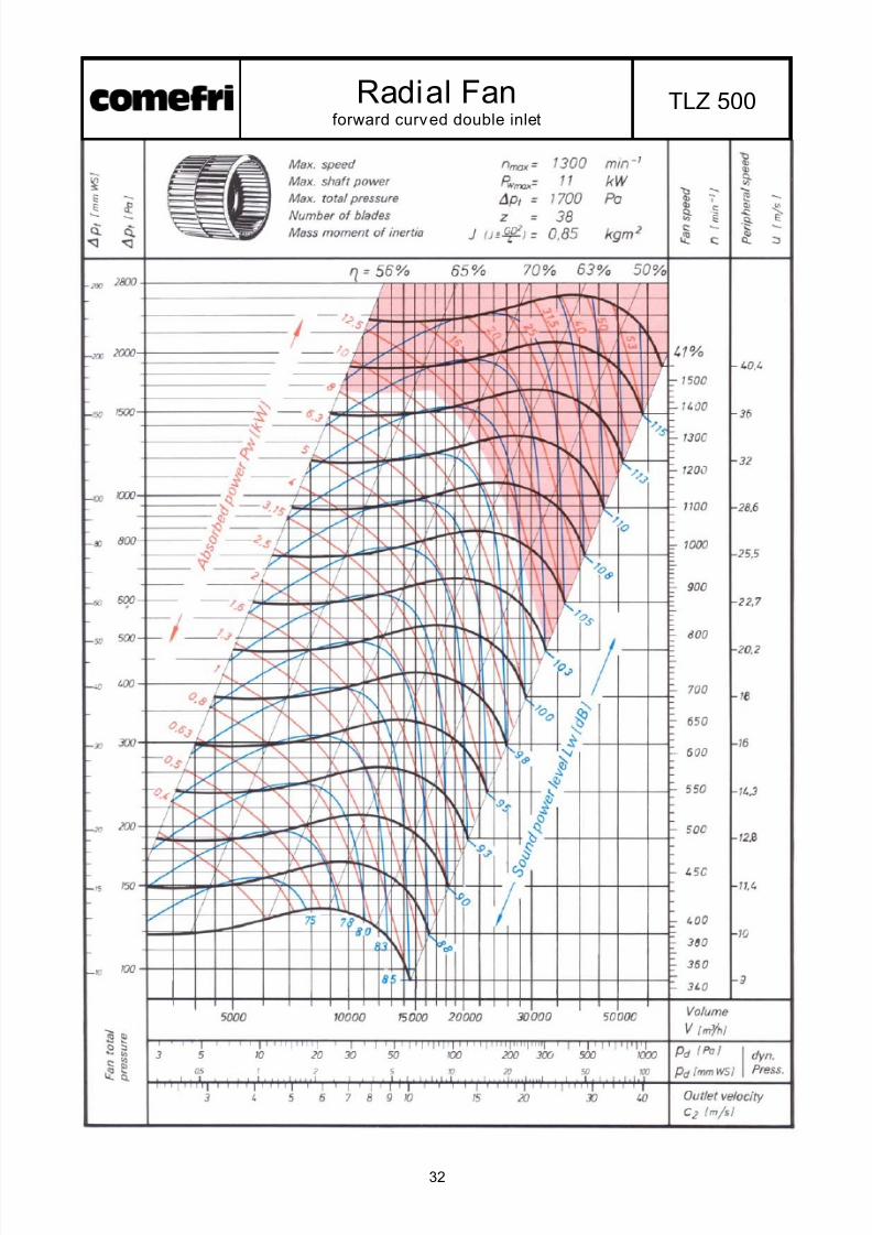
4.3.1 Selection Example of double inlet Fans with highefficiency impeller with forward curved blades, type TLZ
Required:
Volume flow V = 15000 m3/h
Total pressure pt = 1000 Pa
Air density = 1,2 kg/m3
Air temperature t = 293 K (20°C)
To determinate:
Fan size
Speed
Power consumption
Motor output
Efficiency
Sound pressure levelin dB(A) at a distance of 3 m.
Selected from the Curve:Radial Fan TLZ 500
Fan speed n = 990 min-1
Circumferential speed u = 25.9 m/sec.
Dynamic pressure pd = 64 Pa
Static pressure pst = 936 Pa (Total – dynamic pressure)
Outlet velocity c2 = 10.3 m/sec.
Volume flow V = 15000 m3/h
Efficiency = 0.68
Absorbed power PW = 6.1 kW
Motor rating PM = PW + 20%
Suond power level LW = 95 dB
Sound pressure level LPA = 95 – 21 = 74 dB(A)

8/15/2019 C-0024_TLZ-THLZ_04-08
http://slidepdf.com/reader/full/c-0024tlz-thlz04-08 13/46
12
4.3.2 Selection Example of double inlet Fans with highefficiency impeller with backw. curved blades, type THLZ
Required:
Volume flow V = 15000 m3/h
Total pressure pt = 1000 Pa
Air density = 1,2 kg/m3
Air temperature t = 293 K (20°C)
To determinate:
Fan size
Speed
Power consumption
Motor output
Efficiency
Sound pressure levelin dB(A) at a distance of 3 m.
Selected from the Curve:
Radial Fan THLZ . . .
Fan speed n = 1800 min-1
Circumferential speed u = 47.2 m/sec.
Dynamic pressure pd = 64 Pa
Static pressure pst = 936 Pa (Total – dynamic pressure)
Outlet velocity c2 = 10.3 m/sec.
Volume flow V = 15000 m3/h
Efficiency = 0.80
Absorbed power PW = 5.2 kW
Motor rating PM = PW + 15%
Suond power level LW = 95 dB
Sound pressure level LPA = 95 – 21 = 74 dB(A)
THLZ . . .
THLZ

8/15/2019 C-0024_TLZ-THLZ_04-08
http://slidepdf.com/reader/full/c-0024tlz-thlz04-08 14/46
13
Radial Fanbackward curved double inlet
THLZ 180

8/15/2019 C-0024_TLZ-THLZ_04-08
http://slidepdf.com/reader/full/c-0024tlz-thlz04-08 15/46
14
Radial Fanbackward curved double inlet
THLZ 200

8/15/2019 C-0024_TLZ-THLZ_04-08
http://slidepdf.com/reader/full/c-0024tlz-thlz04-08 16/46
15
Radial Fanbackward curved double inlet
THLZ 225
8/15/2019 C-0024_TLZ-THLZ_04-08
http://slidepdf.com/reader/full/c-0024tlz-thlz04-08 17/46
16
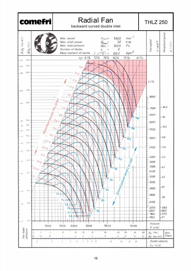
Radial Fanbackward curved double inlet
THLZ 250

8/15/2019 C-0024_TLZ-THLZ_04-08
http://slidepdf.com/reader/full/c-0024tlz-thlz04-08 18/46
17
Radial Fanbackward curved double inlet
THLZ 280

8/15/2019 C-0024_TLZ-THLZ_04-08
http://slidepdf.com/reader/full/c-0024tlz-thlz04-08 19/46
18
Radial Fanbackward curved double inlet
THLZ 315

8/15/2019 C-0024_TLZ-THLZ_04-08
http://slidepdf.com/reader/full/c-0024tlz-thlz04-08 20/46
19
Radial Fanbackward curved double inlet
THLZ 355

8/15/2019 C-0024_TLZ-THLZ_04-08
http://slidepdf.com/reader/full/c-0024tlz-thlz04-08 21/46
20
Radial Fanbackward curved double inlet
THLZ 400

8/15/2019 C-0024_TLZ-THLZ_04-08
http://slidepdf.com/reader/full/c-0024tlz-thlz04-08 22/46
21
Radial Fanbackward curved double inlet
THLZ 450

8/15/2019 C-0024_TLZ-THLZ_04-08
http://slidepdf.com/reader/full/c-0024tlz-thlz04-08 23/46
22
Radial Fanforward curved double inlet
TLZ 160
8/15/2019 C-0024_TLZ-THLZ_04-08
http://slidepdf.com/reader/full/c-0024tlz-thlz04-08 24/46
23
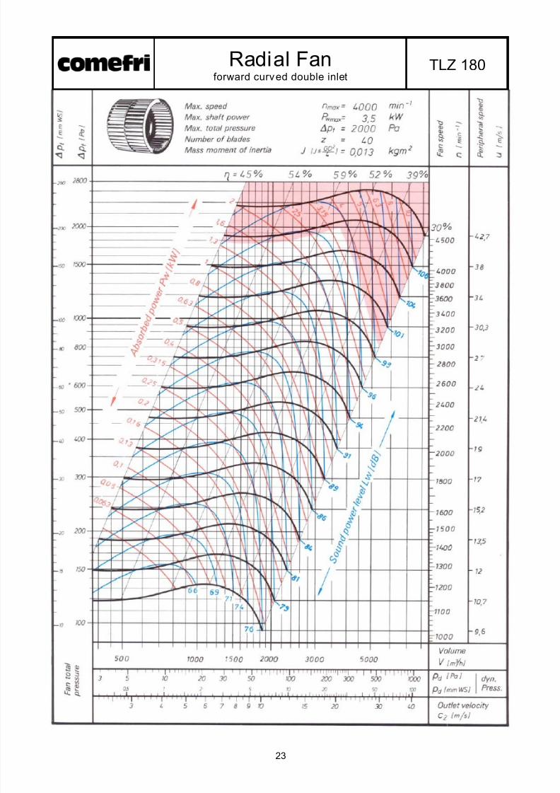
Radial Fanforward curved double inlet
TLZ 180
8/15/2019 C-0024_TLZ-THLZ_04-08
http://slidepdf.com/reader/full/c-0024tlz-thlz04-08 25/46
24
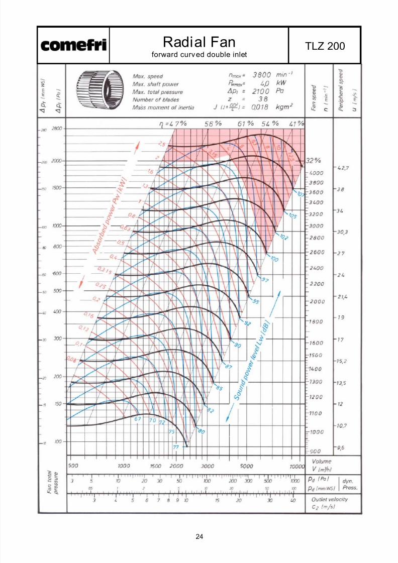
Radial Fanforward curved double inlet
TLZ 200

8/15/2019 C-0024_TLZ-THLZ_04-08
http://slidepdf.com/reader/full/c-0024tlz-thlz04-08 26/46
25
Radial Fanforward curved double inlet
TLZ 225

8/15/2019 C-0024_TLZ-THLZ_04-08
http://slidepdf.com/reader/full/c-0024tlz-thlz04-08 27/46
26
Radial Fanforward curved double inlet
TLZ 250

8/15/2019 C-0024_TLZ-THLZ_04-08
http://slidepdf.com/reader/full/c-0024tlz-thlz04-08 28/46
27
Radial Fanforward curved double inlet
TLZ 280
8/15/2019 C-0024_TLZ-THLZ_04-08
http://slidepdf.com/reader/full/c-0024tlz-thlz04-08 29/46
28
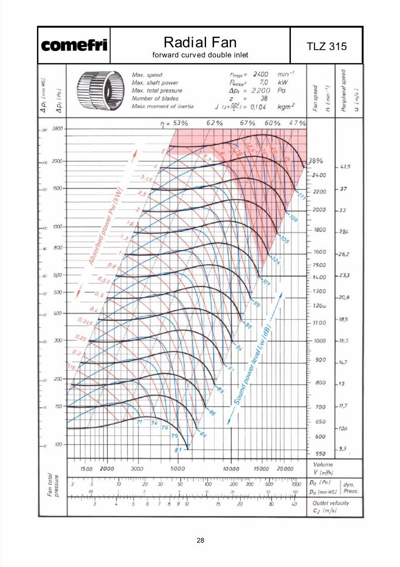
Radial Fanforward curved double inlet
TLZ 315

8/15/2019 C-0024_TLZ-THLZ_04-08
http://slidepdf.com/reader/full/c-0024tlz-thlz04-08 30/46
29
Radial Fanforward curved double inlet
TLZ 355

8/15/2019 C-0024_TLZ-THLZ_04-08
http://slidepdf.com/reader/full/c-0024tlz-thlz04-08 31/46
30
Radial Fanforward curved double inlet
TLZ 400

8/15/2019 C-0024_TLZ-THLZ_04-08
http://slidepdf.com/reader/full/c-0024tlz-thlz04-08 32/46
31
Radial Fanforward curved double inlet
TLZ 450
8/15/2019 C-0024_TLZ-THLZ_04-08
http://slidepdf.com/reader/full/c-0024tlz-thlz04-08 33/46
32
Radial Fanforward curved double inlet
TLZ 500

8/15/2019 C-0024_TLZ-THLZ_04-08
http://slidepdf.com/reader/full/c-0024tlz-thlz04-08 34/46
33
Radial Fanforward curved double inlet
TLZ 560

8/15/2019 C-0024_TLZ-THLZ_04-08
http://slidepdf.com/reader/full/c-0024tlz-thlz04-08 35/46
34
Radial Fanforward curved double inlet
TLZ 630
8/15/2019 C-0024_TLZ-THLZ_04-08
http://slidepdf.com/reader/full/c-0024tlz-thlz04-08 36/46
35
Radial Fanforward curved double inlet
TLZ 710
TLZ 710 T

8/15/2019 C-0024_TLZ-THLZ_04-08
http://slidepdf.com/reader/full/c-0024tlz-thlz04-08 37/46
36
Radial Fanforward curved double inlet
TLZ 800 T

8/15/2019 C-0024_TLZ-THLZ_04-08
http://slidepdf.com/reader/full/c-0024tlz-thlz04-08 38/46
37
Radial Fanforward curved double inlet
TLZ 900 T
8/15/2019 C-0024_TLZ-THLZ_04-08
http://slidepdf.com/reader/full/c-0024tlz-thlz04-08 39/46
38
Radial Fanforward curved double inlet
TLZ 1000 T

8/15/2019 C-0024_TLZ-THLZ_04-08
http://slidepdf.com/reader/full/c-0024tlz-thlz04-08 40/46
39
Radial FanTLZ 160 ÷ 710
TLZ 200 R ÷ 710 R Dimensions and technical details
Drawing
6.1
TLZ A1 A2 a1 a2 a3 C c dh6
d2 d3 f 1 f 2 h1 h2 h3 h4 h5
160 282,5 285 205 230 131 345 25 20 7 7,5 120 153 109 121 145 177 150
180 316,5 319 229 259 149 375 25 20 7 7,5 136 195 119 138 167 200 164
200 342 344 256 286 163 405 25 20 7 7,5 149 216 133 152 180 220 181
225 380 382 288 318 180 435 25 20 7 7,5 167 243 146 169 202 246 197
250 422 420 322 352 199 470 25 20 7 7,5 186 269 159 188 225 273 210
280 464 467 361 391 228 540 25 25 10,5 7,5 208 302 180 211 252 307 233
315 519 519 404 434 240 585 25 25 10,5 7,5 232 341 197 235 283 343 258
355 582 580 453 483 311 655 25 30 10,5 7,5 265 383 222 266 319 389 274
400 645 651 507 537 336 709 25 30 10,5 7,5 295 432 245 300 361 436 302
450 722 722 569 599 382 810 25 35 12 7,5 330 485 270 336 404 492 336
500 795 801 638 668 450 875 25 35 12 7,5 366 538 295 374 449 544 375
560 886 893 715 745 502 1000 25 40 15 7,5 411 601 335 419 503 611 416
630 992 1000 801 831 559 1090 25 40 15 7,5 463 679 370 471 566 687 468
710 1114 1120 898 928 624 1220 25 50 17 7,5 521 765 412 531 636 773 531
TLZ h6 h7 k l p q t1 u v w1 w2 x y1 y2 y3 z1 x t
160 149 204 134 38,5 139,5 71 22,5 6 256 254 298 231 47 69 180 2 x 90
180 164 224 146 41,5 152,5 81 22,5 6 280 286 338 255 53 79 180 2 x 90
200 184 245 162 40,5 164 89 22,5 6 307 314 372 282 45 74 224 2 x 90
225 204 274 178 39,5 180 100 22,5 6 339 348 416 314 62 96 224 3 x 90
250 227 299 195 40 195 109 22,5 6 373 384 462 348 80 119 224 3 x 90
280 252 328 217 53 215 123 28 8 422 432 518 392 76 119 280 3 x 90
315 280 367 239 53 236 139 28 8 466 480 578 436 100 149 280 4 x 90
355 320 411 267 60 261 158 33 8 534 542 655 494 94 150 355 4 x 90
400 359 462 293 61,5 290 179 33 8 588 606 736 549 126 191 355 5 x 90
450 407 518 330 75 322 202 38 10 651 674 828 611 112 189 450 6 x 90
500 448 568 364 73 352 221 38 10 720 744 918 681 147 234 450 6 x 90
560
502 634 406 94 390 248 43 12 818 838 1030 768 169 265 500 7 x 90630 571 707 450 95 434 280 43 12 904 936 1158 854 188 299 560 8 x 90
710 636 797 497 119 485 318 53,5 14 1001 1048 1304 961 209 337 630 9 x 90

8/15/2019 C-0024_TLZ-THLZ_04-08
http://slidepdf.com/reader/full/c-0024tlz-thlz04-08 41/46
40
Radial FanTLZ 710 T ÷ 1000 T
Dimensions and technical details
Drawing
6.2
TLZ A2 a1 a2 a3 C c dh6
d2 d3 h1 h2 h3 h4 k
710 1120 898 928 624 1260 25 50 18 7,5 413 531 635 773 516
800 1256 1007 1037 714 1367 25 50 18 7,5 458 597 716 871 570
900 1409 1130 1164 806 1529 30 60 18 10 507 670 805 978 639
1000 1541 1267 1301 909 1666 30 60 18 10 560 735 884 1075 708
TLZ l p q t1 u v w1 w2 x y1 y2 y3 z1 x t
710 114 485 318 53,5 14 1001 1048 1304 961 209 327 630 9 x 90
800
13 540 359 53,5 14 1111 1174 1468 1071 232 379 710 11 x 90900 125,5 604 406 64 18 1234 1312 1648 1194 256 424 800 11 x 100
1000 125 657 433 64 18 1371 1444 1810 1331 272 455 900 12 x 100

8/15/2019 C-0024_TLZ-THLZ_04-08
http://slidepdf.com/reader/full/c-0024tlz-thlz04-08 42/46
41
Radial FanTHLZ 180 ÷ 450
THLZ 200 R ÷ 450 R Dimensions and technical details
Drawing
6.3
TLZ A1 A2 a1 a2 a3 C c dh6
d2 d3 f 1 f 2 h1 h2 h3 h4 h5
180 316,5 319 229 259 185 375 25 20 7 7,5 136 195 119 138 167 200 164
200 342 344 256 286 166 405 25 20 7 7,5 149 216 133 152 180 220 181
225 380 382 288 318 230 435 25 20 7 7,5 167 243 146 169 202 246 197
250 422 420 322 352 193 470 25 20 7 7,5 186 269 159 188 225 273 210
280 464 467 361 391 227 540 25 25 10,5 7,5 208 302 180 211 252 307 233
315 519 519 404 434 243 585 25 25 10,5 7,5 232 341 197 235 283 343 258
355 582 580 453 483 275 655 25 30 10,5 7,5 265 383 222 266 319 389 274
400 645 651 507 537 305 709 25 30 10,5 7,5 295 432 245 300 361 436 302
450 722 722 569 599 306 810 25 35 12 7,5 330 485 270 336 404 492 336
TLZ h6 h7 k l p q t1 u v w1 w2 x y1 y2 y3 z1 x t
180 164 224 146 41,5 152,5 81 22,5 6 280 286 338 255 53 79 180 2 x 90
200 184 245 162 40,5 164 89 22,5 6 307 314 372 282 45 74 224 2 x 90
225 204 274 178 39,5 180 100 22,5 6 339 348 416 314 62 96 224 3 x 90
250 227 299 195 40 195 109 22,5 6 373 384 462 348 80 119 224 3 x 90
280 252 328 217 53 215 123 28 8 422 432 518 392 76 119 280 3 x 90
315 280 367 239 53 236 139 28 8 466 480 578 436 100 149 280 4 x 90
355
320 411 267 60 261 158 33 8 534 542 655 494 94 150 355 4 x 90400 359 462 293 61,5 290 179 33 8 588 606 736 549 126 191 355 5 x 90
450 407 518 330 75 322 202 38 10 651 674 828 611 112 189 450 6 x 90

8/15/2019 C-0024_TLZ-THLZ_04-08
http://slidepdf.com/reader/full/c-0024tlz-thlz04-08 43/46
42
Radial FanTLZ 160 to 710 and THLZ 180 to 450
Side plate
Table
6.4
Fan size
TLZ THLZa1 b1 c f 1 f 2 f 3 g1 g2 g3 g4 x1 x2 x3 y1 y2 y3 *
160 - 30 30 30 - - - 155 101 101 101 121 92 67 92 67 92 B 6,3
180 180 30 30 30 - - - 175 115 115 115 141 92 81 92 81 92 B 6,3
200 200 40 40 40 202 163 134 190 129 126 126 155 110 91 110 94 110 B 6,3
225 225 40 40 40 229 185 152 219 149 142 142 184 110 107 110 114 110 B 6,3
250 250 40 40 40 256 208 171 244 172 155 155 209 110 120 110 137 110 B 6,3
280 280 113 113 71 287 233 191 245 169 150 170 - - - - - - B 8
315 315 113 113 71 323 263 215 284 197 175 195 - - - - - - B 8
355 355 156 156 156 364 295 241 295 204 158 158 197,5 - - 197,5 - - B 8
400 400 156 156 156 411 336 275 346 243 186 186 220 - - 220 - - B 8
450 450 213 213 213 466 379 311 350 271 168 168 245 - - 245 - - M 10
500 - 213 213 213 519 423 349 400 280 207 207 270 - - 270 - - M 10
560 - 235 235 235 581 472 389 494 362 276 276 305 - - 305 - - M 12
630 - 235 235 235 656 535 441 567 431 328 328 340 - - 340 - - M 12
710 - 265 265 265 717 601 496 637 476 371 371 377,5 - - 377,5 - - M 12
TLZ and THLZ Fan and accessories weights (in Kg) Table 6.5
Fan size TLZ TLZ…T THLZ THLZ...TInlet vane
controlFeet Frame Outlet flange
160 5.1 - - - - 0.5 0.5 0.66
180 6.0 - 6.3 - - 0.5 0.5 0.72
200 7.2 - 7.2 - - 0.8 0.8 0.80225 8.5 - 8.2 - - 0.8 0.8 0.88
250 10.8 - 10.2 - - 0.8 0.8 0.97
280 14.5 - 14.2 - - 1.0 1.0 1.07
315 20.0 - 19.4 - 12 1.0 1.0 1.20
355 26.5 - 26.3 - 14 2.0 2.0 1.35
400 32.0 - 31.5 - 18 2.0 2.0 1.50
450 42.0 - 41.2 - 21 3.7 3.7 1.70
500 56.0 - - - - 3.7 3.7 1.90
560 76.0 - - - - 7.5 7.5 2.00
630 96.0 - - - - 7.5 7.5 2.30
710 125 190 - 208 - 11.0 11.0 2.60
800 - 230 - 249 - - - 2.90
900 - 288 - 321 - - - 3.90
1000 - 333 - 380 - - - 4.40
8/15/2019 C-0024_TLZ-THLZ_04-08
http://slidepdf.com/reader/full/c-0024tlz-thlz04-08 44/46
43
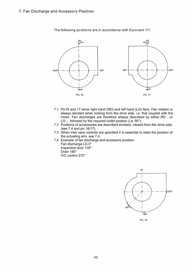
7. Fan Discharge and Accessory Posit ion
The follow ing positions are in accordance with Eurovent 1/1.
Pic 16 Pic 17
7.1
7.2 7.3 7.4
Pic16 and 17 show right hand (RD) and left hand (LG) fans. Fan rotation isalways decided when looking from the drive side, i.e. that coupled with themotor. Fan discharges are therefore always described by either RD ...orLG ... followed by the required outlet position (i.e. 90°).Positions of accessories are described similarly, viewed from the drive side.(see 7.4 and pic 16/17).When inlet vane controls are specified it is essential to state the position ofthe actuating arm, see 7.4.Example of fan discharge and accessory position:Fan discharge LG 0°Inspection door 135°Drain 180°IVC control 270°
Pic 18

8/15/2019 C-0024_TLZ-THLZ_04-08
http://slidepdf.com/reader/full/c-0024tlz-thlz04-08 45/46
44
8. Instruct ions for Ordering and Specifying
Pic 19Radial Fan TLZ 400 F
Pic 20Radial Fan TLZ 500 R
8.1 All standard fans are detailed on drawings 6.1, 6.2 and 6.3.To order or specify fans they must be described as follows:Fan range either TLZ, THLZFan size which represents the diameter of impellers in mm (i.e. TLZ 450 orTHLZ 450).
8.2 Accessories are represented by the following symbols:
F ARDrIKEx
=======
FeetOutlet flangeFan frameInlet vane controlInspection doorCondensation drain Anti-Spark Feature
Fan accessories should be specified when ordering fans.
Example 1 (see Pic 19):
Fan TLZ 400 with feet TLZ 400 F
Example 2 (see Pic 20):Fan TLZ 500 with outlet flange and fan frame TLZ 500 RA
8.3 Fan sizes TLZ 710 and THLZ 450 can be supplied as standard with orwithout frames. see (6.1 and 6.3)
Pic 21Ordering Example.
8.4 Ordering Example
To order a THLZ 355 with discharge position LG 90° plus feet, outlet flange,inspection door, drain and inlet vane control.Order as follows:THLZ 355 A - LG 90° I 225° Dr 0° K 180° F-355
The fans described in this catalogue are suitable for many and varied applica-
tions; but should you require special versions a complete technical team existsto assist and advise.Due to improvements which are introduced from time to time the company re-serves the right to alter the products specified in this catalogue.

8/15/2019 C-0024_TLZ-THLZ_04-08
http://slidepdf.com/reader/full/c-0024tlz-thlz04-08 46/46
COMEFRI reserves the right to make any dimensional design changes which are part of their improvement programme.Necessary corrections are updated on our AEOLUS PLUS selection program.
Note:
This catalogue has to be used only for pre-selections. A detailed selection is available from our AEOLUSPLUS selection program.
Comefri SpA Comefri GmbH Comefri France S.A.
Via Buja, 3I-33010 Magnano in Riviera (UD)ItalyTel. +39-0432-798811Fax +39-0432-783378 www.comefri.comE-mail: [email protected]
Landshuter Str.5584030 ErgoldingGermanyTel. +49-871-43070-0Fax +49-871-43070-40www.comefri.deE-mail: [email protected]
10, Rue des Frères Lumière69740 GenasFranceTel. +33-4-72 79 03 80Fax +33-4-78 90 69 73www.comefri.comE-mail: [email protected]
Comefri UK Ltd Comefri Nordisk ApS Comefri USA, Inc
Carters Lane, 8 Kiln FarmMilton Keynes, MK11 3 ERGreat BritainTel. +44-1908-56 94 69Fax +44-1908-56 75 66www.comefri.comE-mail: [email protected]
Mileparken, 18DK 2740 SkovlundeDenmarkTel. +45-44-92 76 00Fax +45-44-92 55 33 www.comefri.comE-mail: [email protected]
330 BilI Bryan BoulevardHopkinsville, KY 42240USATel. +1-270-881-1444Fax + 1-270-889-0309www.comefriusa.comE-mail: [email protected]