Embed Size (px)
Citation preview

c© 2019
Shreyasee Mukherjee
ALL RIGHTS RESERVED

NETWORK PROTOCOLS FOR THEMOBILITY-CENTRIC FUTURE INTERNET
by
SHREYASEE MUKHERJEE
A dissertation submitted to the
School of Graduate Studies
Rutgers, The State University of New Jersey
In partial fulfillment of the requirements
For the degree of
Doctor of Philosophy
Graduate Program in Electrical and Computer Engineering
Written under the direction of
Dipankar Raychaudhuri
And approved by
New Brunswick, New Jersey
January, 2019

ABSTRACT OF THE DISSERTATION
Network Protocols for the Mobility-Centric Future
Internet
By SHREYASEE MUKHERJEE
Dissertation Director:
Dipankar Raychaudhuri
This thesis presents network protocol solutions to support advanced services in the
future Internet. The Internet is increasingly becoming mobile with the number of mobile
end-points far exceeding the fixed hosts. At the same time, new classes of services need
to be supported with vastly different requirements than traditional end-hosts such as low
power internet-of-things (IoTs) and highly mobile vehicular platforms. The TCP/IP
network architecture developed with static end-hosts in mind fails to meet many of
these requirements and there is a need for a fundamental rethinking of the network
protocols in order to support these requirements in the future Internet.
The thesis starts with a comprehensive analysis of different emerging network access
scenarios and identifies the set of requirements to support such use-cases, including basic
host and network mobility, wireless link variation, disconnection, IoT data forwarding,
and content and contextual delivery. It then introduces the concept of a named-object
architecture which is designed from ground-up keeping such requirements in mind and
presents an overview of MobilityFirst as a potential named-object architectural solution.
Chapter 3 presents an edge-aware inter-domain routing (EIR) protocol which pro-
vides new abstractions of aggregated-nodes (aNodes) and virtual-links (vLinks) for
ii

expressing network topologies and edge network properties necessary to address next-
generation mobility related routing scenarios and link quality variations which are in-
adequately supported by the border gateway protocol (BGP) in use today. Specific
use-cases addressed by EIR include emerging mobility service scenarios such as rout-
ing support for mobile networks in vehicular scenarios, multipath routing over several
access networks, and anycast services from mobile devices to replicated cloud services.
Simulation results for protocol overhead are presented and a proof-of-concept imple-
mentation on the ORBIT testbed is used to validate performance for selected mobility
use-cases.
In Chapter 4, we propose a novel push-based inter-domain multicast that leverages
on the concept of named-objects and a distributed name-resolution service to maintain
large-scale multicast trees. The proposed named-object multicast (NOMA) protocol
achieves improved scalability and performance over conventional protocols such as PIM-
SM and MSDP by simplifying multicast tree generation and management. NOMA also
handles mobility of end-users, thereby allowing them to move dynamically between
networks, while being associated to a multicast group. Performance evaluation results,
including comparisons with IP multicast, are given using a combination of analysis and
NS-3 simulation. The results show good scalability properties along with low control
overhead for medium to large multicast groups.
Chapter 5 presents qualitative and quantitative comparison of the proposed proto-
cols to alternative name-based architectural solutions, such as content centric network-
ing (CCN) as well as protocols evolved from IP, i.e. host identity protocol (HIP) and
location identifier separation protocol (LISP).
Finally, in Chapter 6, we explore the 3GPP 5G core network architecture and pro-
pose named-object protocol solutions to improve control overhead for latency-sensitive
applications such as IoTs and AR/VR utilizing the cellular access network and co-
located mobile edge cloud. Large scale simulation using real-world datasets and proof-
of-concept prototype show improved control overhead and latency for heterogeneous
access scenarios.
iii

Acknowledgements
I will start by thanking my advisor Dr. Dipankar Raychaudhuri. I honestly believe he
is the best advisor I could have ever hoped for and more. After seven years under his
mentorship, I am still surprised by his patience and diligence at every little problem I put
forward to him. He has continuously piqued my curiosity for new research problems,
and, at the same time, provided me enough flexibility to have an amazing work-life
balance and to enjoy every moment of my graduate career. I came in as a naive
masters student, confused and pessimistic at my own abilities and he painstakingly
taught me how to conduct proper research, write technical papers, how to present my
work confidently, and network effectively. Moving forward, I do hope I can aspire to the
life principles he has always taught me: hard work, honesty, and to stand your ground
when you need to.
This thesis would not have been complete without the valuable inputs of my proposal
and defense committee members, namely, Dr. Narayan Mandayam, Dr. Ravishankar
Ravindran, Dr. Roy Yates, Dr. Wade Trappe and, Dr. Yanyong Zhang. Dr. Roy Yates
spent many hours understanding and shaping the research problems to a tangible so-
lution. I only wish for continuing collaboration in all the interesting and yet unsolved
ideas we discussed but could not complete. Dr. Ravishankar Ravindran devoted his
time to go in-depth into my simulations and prototyping code providing valuable feed-
back whenever I was stuck. Ivan Seskar also deserves special mention, as he has always
been there, to provide the bigger picture and to direct my research towards practical
solutions and implementations relevant to the community. Not to mention, his numer-
ous invaluable travel suggestions and the amazing hikes he took me to while attending
technical conferences.
I cannot thank my family enough for supporting me through thick and thin. Back
iv

from India, my parents, being eternally worried about my thesis prospects, made sure
that I stayed on track and motivated me over countless phone conversations, to keep on
doing what I love. My brother and sister-in-law, at every given opportunity, pampered
me with food, comfort, and unconditional love. I have also been blessed with awesome
lab-mates who became the closest of friends including Francesco, Parishad, Ratnesh
and, Shubham, without whom, it is impossible to imagine my life at WINLAB. I learned
to enjoy life to the fullest with you all and hope we keep at it for years to come.
v

Dedication
To my parents who always wanted me to be a doctor someday
vi

Table of Contents
Abstract . . . . . . . . . . . . . . . . . . . . . . . . . . . . . . . . . . . . . . . . ii
Acknowledgements . . . . . . . . . . . . . . . . . . . . . . . . . . . . . . . . . iv
Dedication . . . . . . . . . . . . . . . . . . . . . . . . . . . . . . . . . . . . . . . vi
List of Tables . . . . . . . . . . . . . . . . . . . . . . . . . . . . . . . . . . . . . x
List of Figures . . . . . . . . . . . . . . . . . . . . . . . . . . . . . . . . . . . . xi
1. Introduction . . . . . . . . . . . . . . . . . . . . . . . . . . . . . . . . . . . 1
1.1. Organization of the thesis . . . . . . . . . . . . . . . . . . . . . . . . . . 2
2. Mobile Internet Requirements and the Named Object Abstraction 4
2.1. Mobile Network and Wireless Access Requirements . . . . . . . . . . . . 4
2.1.1. Host and Network Mobility . . . . . . . . . . . . . . . . . . . . . 4
2.1.2. Varying Wireless Link Quality and Disconnection . . . . . . . . . 5
2.1.3. Accessing Multiple Networks . . . . . . . . . . . . . . . . . . . . 6
2.1.4. Adhoc Networks . . . . . . . . . . . . . . . . . . . . . . . . . . . 6
2.1.5. Content and Context Addressability . . . . . . . . . . . . . . . . 7
2.1.6. Authentication and Security . . . . . . . . . . . . . . . . . . . . . 8
2.1.7. Spectrum Access Coordination . . . . . . . . . . . . . . . . . . . 9
2.2. A Named-Object Solution . . . . . . . . . . . . . . . . . . . . . . . . . . 9
2.3. MobilityFirst: A Named-Object Architecture . . . . . . . . . . . . . . . 11
2.4. Mobility Support in a Name Based Architecture . . . . . . . . . . . . . 12
2.5. Protocol Design Using Named-Objects . . . . . . . . . . . . . . . . . . . 13
3. Edge Aware Inter-domain Routing . . . . . . . . . . . . . . . . . . . . . 14
vii

3.1. Introduction . . . . . . . . . . . . . . . . . . . . . . . . . . . . . . . . . . 14
3.2. Emerging Network Service Use-cases . . . . . . . . . . . . . . . . . . . . 16
3.3. EIR Protocol Design . . . . . . . . . . . . . . . . . . . . . . . . . . . . . 18
3.3.1. Design concepts . . . . . . . . . . . . . . . . . . . . . . . . . . . . 18
3.3.2. Protocol building blocks . . . . . . . . . . . . . . . . . . . . . . . 20
Aggregated nodes (aNodes) and virtual links (vLinks): . . . . . . 21
Route dissemination through network state packets: . . . . . . . 23
Telescopic flooding of network state: . . . . . . . . . . . . . . . . 26
Late-binding for mobility support: . . . . . . . . . . . . . . . . . 27
Label based path-setup: . . . . . . . . . . . . . . . . . . . . . . . 28
3.3.3. Supported routing algorithms . . . . . . . . . . . . . . . . . . . . 30
3.3.4. EIR routing examples . . . . . . . . . . . . . . . . . . . . . . . . 32
3.4. Policy Specifications . . . . . . . . . . . . . . . . . . . . . . . . . . . . . 34
3.5. Evaluation . . . . . . . . . . . . . . . . . . . . . . . . . . . . . . . . . . . 38
3.5.1. Overhead and scalability studies . . . . . . . . . . . . . . . . . . 38
3.5.2. Prototype evaluation . . . . . . . . . . . . . . . . . . . . . . . . . 45
3.6. Related Work . . . . . . . . . . . . . . . . . . . . . . . . . . . . . . . . . 49
3.7. Summary . . . . . . . . . . . . . . . . . . . . . . . . . . . . . . . . . . . 51
4. Named Object Multicast . . . . . . . . . . . . . . . . . . . . . . . . . . . 53
4.1. Introduction . . . . . . . . . . . . . . . . . . . . . . . . . . . . . . . . . . 53
4.2. NOMA Design . . . . . . . . . . . . . . . . . . . . . . . . . . . . . . . . 57
4.2.1. Multicast Tree Management . . . . . . . . . . . . . . . . . . . . . 57
4.2.2. Data Forwarding . . . . . . . . . . . . . . . . . . . . . . . . . . . 59
4.2.3. Handling Mobility: . . . . . . . . . . . . . . . . . . . . . . . . . . 60
4.3. Evaluation . . . . . . . . . . . . . . . . . . . . . . . . . . . . . . . . . . . 62
4.3.1. Tree Generation Algorithms . . . . . . . . . . . . . . . . . . . . . 62
4.3.2. Comparison to IP multicast . . . . . . . . . . . . . . . . . . . . . 63
4.3.3. Prototype Description . . . . . . . . . . . . . . . . . . . . . . . . 67
viii

4.4. Summary . . . . . . . . . . . . . . . . . . . . . . . . . . . . . . . . . . . 68
5. Comparison to Alternative Name-based Architectures . . . . . . . . . 69
5.1. Introduction . . . . . . . . . . . . . . . . . . . . . . . . . . . . . . . . . . 69
5.1.1. Handling Mobility . . . . . . . . . . . . . . . . . . . . . . . . . . 69
5.1.2. Enabling Device Multihoming . . . . . . . . . . . . . . . . . . . . 71
5.1.3. Support for Large Multicast Groups . . . . . . . . . . . . . . . . 72
5.2. Evaluation . . . . . . . . . . . . . . . . . . . . . . . . . . . . . . . . . . . 73
5.2.1. Device Mobility Support . . . . . . . . . . . . . . . . . . . . . . . 74
5.2.2. Multihoming support . . . . . . . . . . . . . . . . . . . . . . . . 77
5.2.3. Multicast Support . . . . . . . . . . . . . . . . . . . . . . . . . . 78
5.3. Summary . . . . . . . . . . . . . . . . . . . . . . . . . . . . . . . . . . . 79
6. A Distributed Mobile Core . . . . . . . . . . . . . . . . . . . . . . . . . . 80
6.1. Introduction . . . . . . . . . . . . . . . . . . . . . . . . . . . . . . . . . . 80
6.1.1. Current Cellular Core Network Design . . . . . . . . . . . . . . . 82
6.1.2. Motivation for a flat core network . . . . . . . . . . . . . . . . . 83
6.2. A Flat Cellular Core Design . . . . . . . . . . . . . . . . . . . . . . . . . 87
6.2.1. Architecture Overview . . . . . . . . . . . . . . . . . . . . . . . . 87
6.2.2. Dataplane Services . . . . . . . . . . . . . . . . . . . . . . . . . . 92
6.3. Evaluation . . . . . . . . . . . . . . . . . . . . . . . . . . . . . . . . . . . 95
6.3.1. Control overhead simulation . . . . . . . . . . . . . . . . . . . . . 95
6.3.2. Prototype Evaluation . . . . . . . . . . . . . . . . . . . . . . . . 100
6.4. Related Work . . . . . . . . . . . . . . . . . . . . . . . . . . . . . . . . . 102
6.5. Summary . . . . . . . . . . . . . . . . . . . . . . . . . . . . . . . . . . . 103
7. Conclusions . . . . . . . . . . . . . . . . . . . . . . . . . . . . . . . . . . . . 105
7.1. Looking Ahead . . . . . . . . . . . . . . . . . . . . . . . . . . . . . . . . 106
References . . . . . . . . . . . . . . . . . . . . . . . . . . . . . . . . . . . . . . . 107
ix

List of Tables
3.1. Comparative analysis of policy support in EIR, Pathlet and BGP . . . . 35
3.2. Probabilistic transition for user mobility . . . . . . . . . . . . . . . . . . 47
4.1. Emerging multicast application and their characteristics . . . . . . . . . 54
5.1. Topology and mobility trace information . . . . . . . . . . . . . . . . . . 74
6.1. Simulation Parameters . . . . . . . . . . . . . . . . . . . . . . . . . . . . 96
x

List of Figures
2.1. The Named-Object abstraction applied to different use cases, reproduced
from [1] . . . . . . . . . . . . . . . . . . . . . . . . . . . . . . . . . . . . 10
2.2. The MobilityFirst architecture overview . . . . . . . . . . . . . . . . . . 11
2.3. Mobility and mulltihoming support using named-objects in the Mobili-
tyFirst architecture . . . . . . . . . . . . . . . . . . . . . . . . . . . . . . 12
3.1. aNode-vLink topology abstraction for an AS, reproduced from [2] . . . . 21
3.2. Inter-AS route update structure exchanged through network state pack-
ets (nSPs) between border routers . . . . . . . . . . . . . . . . . . . . . 23
3.3. CDF of AS path length of 2000 randomly chosen ASes in the Internet
using BGP; Dijkstra based link state routing highlights the lower bound
for the path lengths . . . . . . . . . . . . . . . . . . . . . . . . . . . . . 24
3.4. Shape of telescopic functions of hop count vs. hold delay for A = 3 . . . 26
3.5. Late-binding of data to counter stale network state update at a far-away
node . . . . . . . . . . . . . . . . . . . . . . . . . . . . . . . . . . . . . . 28
3.6. Border routers generate paths with labels that are injected into the fast
path table at the internal routers along the path . . . . . . . . . . . . . 29
3.7. Telescopic flooding and support for multiple shortest paths based on SIDs 31
3.8. A multi-homing scenario highlighting data delivery to client E2 through
two interfaces . . . . . . . . . . . . . . . . . . . . . . . . . . . . . . . . . 32
3.9. Delay tolerant delivery to mobile client E2 using late-binding . . . . . . 33
3.10. CDF of inter-AS latency in the Dimes topology and in our 200 node
synthetic topology . . . . . . . . . . . . . . . . . . . . . . . . . . . . . . 38
xi

3.11. (a) CDF of receiving an update at each AS for different types of telescopic
functions, and, (b) that with different percentile of recipients for const-
exp-const telescopic function . . . . . . . . . . . . . . . . . . . . . . . . 40
3.12. (a) Overhead vs. settling time for different parameters of the constant-
exponential-constant telescopic function, and, (b) Average and worst
case load on links for values that provide a good tradeoff . . . . . . . . . 41
3.13. Data delivery to an end-host, with core link failure in EIR . . . . . . . . 42
3.14. Inter-domain table size at each border router for different levels of ag-
gregation . . . . . . . . . . . . . . . . . . . . . . . . . . . . . . . . . . . 43
3.15. Overview of the Click router prototype for border and internal routers . 46
3.16. CDF of path stretch with and without late binding for end-user mobility 48
3.17. Data delivery failure rate for different telescopic update intervals for
network mobility . . . . . . . . . . . . . . . . . . . . . . . . . . . . . . . 49
4.1. Hierarchical tree structure maintained in a name resolution service, with
names of tree nodes recursively mapping to routable addresses . . . . . 56
4.2. Multicast architecture overview, reproduced from [3] . . . . . . . . . . . 58
4.3. Tree building steps comparison of NOMA with IP multicast . . . . . . . 59
4.4. Device mobility handling through unicast repair messages . . . . . . . . 61
4.5. CDF of total packet hops in terms of packet hops for different multicast
tree generation algorithms, for 100 node random graph with 20 randomly
chosen destination nodes. . . . . . . . . . . . . . . . . . . . . . . . . . . 64
4.6. Control packet overhead for tree setup for varying graph sizes . . . . . . 65
4.7. Comparison of average multicast throughput received at a client with
mobility . . . . . . . . . . . . . . . . . . . . . . . . . . . . . . . . . . . . 66
4.8. Aggregate throughput at a mobile client, with increasing mean mobility
rates; mobility event is determined by an exponential random variable
with the mean . . . . . . . . . . . . . . . . . . . . . . . . . . . . . . . . 67
4.9. Components of the NOMA router prototype, GNRS and client imple-
mentation, with developed modules shown in blue . . . . . . . . . . . . 68
xii

5.1. Mobility management techniques: pure name based, end-host based and
NRS based . . . . . . . . . . . . . . . . . . . . . . . . . . . . . . . . . . 70
5.2. Multihoming techniques: pure name based, end-host based and resolution-
service based . . . . . . . . . . . . . . . . . . . . . . . . . . . . . . . . . 71
5.3. NRS multicast tree overloading compared to name based polling approach. 73
5.4. Control overhead comparison for (a) maintaining mobility and, (b) using
a single replica NRS . . . . . . . . . . . . . . . . . . . . . . . . . . . . . 75
5.5. Data delivery to a moving vehicle while it disassociates and re-associates
with WiFi APs . . . . . . . . . . . . . . . . . . . . . . . . . . . . . . . . 76
5.6. Control overhead for multihoming support with increasing number of
interfaces in a 1000 network random graph . . . . . . . . . . . . . . . . 77
5.7. Control overhead for multicast tree maintenance in a 1000 network ran-
dom graph (single source and multiple receivers) . . . . . . . . . . . . . 78
6.1. The 5G network architecture: functional services and physical resources 81
6.2. Control messaging to establish uplink data connectivity for a user equip-
ment (UE) using 4G . . . . . . . . . . . . . . . . . . . . . . . . . . . . . 82
6.3. MF-Core Architecture with breakdown of key functionalities handled
distributedly at the eNBs . . . . . . . . . . . . . . . . . . . . . . . . . . 87
6.4. Comparison of end-to-end protocol stack for 6.4(a) LTE and 6.4(b) MF 88
6.5. Control messaging to establish uplink data connectivity for an UE using
Mf-Core . . . . . . . . . . . . . . . . . . . . . . . . . . . . . . . . . . . . 89
6.6. Control and data plane for the distributed core with named object iden-
tifiers and distributed mapping service . . . . . . . . . . . . . . . . . . . 90
6.7. Enabling VOIP call between two subscribers of the same network through
the distributed core . . . . . . . . . . . . . . . . . . . . . . . . . . . . . . 93
6.8. Instantiating flexible services and QoS policies in the distributed core
network . . . . . . . . . . . . . . . . . . . . . . . . . . . . . . . . . . . . 94
6.9. Mobile edge computing in 5G (left) and in the distributed flat core (right) 95
xiii

6.10. UE wakeup intervals for smartphones (real-world data) and IoTs (syn-
thetic data) . . . . . . . . . . . . . . . . . . . . . . . . . . . . . . . . . . 97
6.11. Control overhead at each PGW, SGW and MME for subscribers of an
US-scale carrier for the year 2017 and forecasted increase for 2021. . . . 98
6.12. Control overhead at each of the locations of the distributed mapping
system for the year 2017 and forecasted increase for 2021. . . . . . . . 99
6.13. Data flow path length for 10,000 random pairs of UEs, both subscribed
to the cellular network . . . . . . . . . . . . . . . . . . . . . . . . . . . 100
6.14. Prototype setup for experimenting with the distributed core . . . . . . . 101
6.15. Experimental results for network layer latency during connection estab-
lishment . . . . . . . . . . . . . . . . . . . . . . . . . . . . . . . . . . . . 102
6.16. Latency comparison for connection establishment in a distributed core
vs. a commercial cellular network provider . . . . . . . . . . . . . . . . . 103
xiv

1
Chapter 1
Introduction
The Internet has crossed an inflection point where wireless/mobile devices have over-
taken wired PCs as the primary end-user device. Worldwide mobile device usage contin-
ues to grow at an exponential rate. The Cisco VNI Global Mobile Data Traffic Forecast
2021 [4] predicts that mobile data traffic alone will account for 48.3 exabytes/month
by 2021, growing twice as fast as fixed IP. This fundamental shift in Internet usage
presents a unique and timely opportunity to consider the requirements and wireless
access challenges from the ground-up and provide protocol solutions to address them.
The current TCP/IP based Internet protocol framework has several limitations when
applied to wireless access scenarios with mobile endpoints. IP address assignment and
management via protocols such as DHCP and DNS are relatively static while TCP
assumes the existence of a bi-directional end-to-end path. In addition, IP addresses
serve the dual roles of end-point identifier and routable network locator, making it
difficult to deal with many aspects of dynamic mobility such as disconnection or multi-
network access. Incremental network and transport layer solutions (e.g. Mobile IP [5],
TCP Multipath [6]) aim to tackle only part of the problem, whereas clean slate nam-
ing conventions like the Host Identity Protocol (HIP) [7] and the Location Identifier
Separation Protocol (LISP) [8] concentrate primarily on the name-address separation
issue. As mobile networks expand to encompass everything around us in a “connected
world”, 3GPP evolution 5G access aims to provide improved last mile connectivity. It
is anticipated that the future 5G access standard will support gigabit bandwidth and
millisecond latencies to meet the requirements of the diverse set of services, applica-
tion and users [9–11]. However networking solutions for cellular mobile data service
continue to involve both 3GPP and IP protocols with all the limitations of multiple

2
protocol architectures and associated gateway processing.
This motivates us to understand the requirements of the future mobile internet, its
heterogeneous devices and access networks, routers and associated protocols, use-cases
and services in order to propose solutions that aim to address the limitations.
1.1 Organization of the thesis
In the following chapter, we first discuss the wireless access and mobility service re-
quirements for an Internet-connected end-point. A named-object architectural solu-
tion is then proposed to meet basic mobility and wireless access use-cases. The next
part of the thesis goes into details of the protocols that now need to enabled using the
named-objects in order to support the advanced network use-cases such as inter-domain
mobility and large scale multicast.
In chapter 3 we describe an inter-domain routing protocol that proposes aggregate
network abstractions based on names which can be utilized by autonomous systems
to expose an internal topology graph. This in turn enables inter-domain mobility for
end-hosts as well as networks with reasonable network overheads in comparison to the
border gateway protocol (BGP) in use today.
Chapter 4 introduces a named-object multicast protocol to support an efficient
inter-domain multicast scheme that leverages on the name-address separation concept
and builds large multicast trees stored distributedly across the network. The proposed
framework can run any multicast tree-generation algorithm and allows mobile receivers
to seamlessly join and leave a group without loss of data.
Chapter 5 brings all the proposed components together and provides a detailed qual-
itative and quantitative evaluation of the named-object architecture with its protocol
enhancements to alternative name-based architecture designs such as Content Centric
Networking (CCN), and protocols evolved from IP, i.e. HIP and LISP.
Finally, in chapter 6 we describe our latest work on protocol advancements for the
3GPP cellular core network architecture. Specifically we focus on low latency applica-
tions such as internet of things (IoT) and augmented reality/virtual reality applications

3
utilizing the cellular access network and its co-located mobile edge cloud, where low
latency is a critical requirement. The proposed protocols leverage on the named-object
architecture with its self-certifying names for device authentication and on-boarding
and the distributed name-resolution service for mobility management. We present re-
sults from large scale simulations as well as prototyping with open-source components
and software radios with experiments on the ORBIT testbed. The experimental evalua-
tion brings together all components of the proposed architecture together in a software
mobile core package that supports distributed mobility, heterogeneous network access,
multihoming and multicast.

4
Chapter 2
Mobile Internet Requirements and the Named Object
Abstraction
The thesis starts with a top-down analysis of the requirements for the future Internet
which are not well-supported in the current architecture. It then introduces the con-
cept of named-objects and how the concept of separating names from addresses of an
endpoint results in mitigating many of these limitations.
2.1 Mobile Network and Wireless Access Requirements
In this section, we analyze specific wireless access and mobility service requirements
and identify the corresponding protocol implications for their support.
2.1.1 Host and Network Mobility
The primary characteristic of mobile nodes is that their points of attachment to the
Internet can change easily and rapidly. The need for supporting mobility arises when
an individual node or a group of nodes, for example a bus/train/plane network, moves
and reconnects to the Internet. Previous studies on opportunistic WiFi through ve-
hicular nodes have shown that mobile nodes suffer frequent disconnections (at a mean
periodicity of 75 seconds). In addition, nodes change their IP addresses every time
they associate with a new access point (median connectivity period is only 13 seconds
for vehicular mobility in an urban scenario) [12]. A cellular network provider performs
handover between its basestations transparent to the user, enabling them to hold on
to their static IP address assigned by the network provider. However data is routed
through a gateway which is a bottleneck for both control and data traffic as described
in detail in chapter 6. In this regard, Mobile IP tries to achieve the same with the use

5
of fixed mobility anchors [5]. However, the concept of having a fixed “home network”
with infrequent network transitions, is changing. Given host names and their actual lo-
cations are increasingly becoming uncorrelated, a fundamental requirement for mobility
support is to separate the two and identify hosts only via a permanent name.
This functional requirement can be translated to the following protocol design re-
quirements:
(A.1) Disambiguation of the dual-roles of an IP address as both an identifier and a
locator into two different primitives - a permanent name and a network-specific
temporary locator.
(A.2) Dynamic binding of names to network addresses/locators.
(A.3) Support for weak connectivity and disconnection in wireless environments.
2.1.2 Varying Wireless Link Quality and Disconnection
Achievable bit rates in both WiFi and LTE systems, can show large variations within
a fraction of a second. Temporary disconnections due to mobility and/or insufficient
signal strength is also common. While these variations are usually handled at the PHY
and MAC layers, they invalidate some implicit assumptions in the control algorithms
used in the Internet. For example, it has been long known that TCP congestion control
treats wireless link errors as congestion losses and performs poorly in high-variation
and multi-hop wireless channels [13]. Given the last mile connectivity is increasingly
becoming wireless, such link quality variations need to be natively supported at different
layers of the Internet architecture. This leads to the following requirements:
(B.1) Link quality awareness at both the intra-domain and inter-domain routing layers
to enable robust packet delivery strategies.
(B.2) Disconnection-tolerant routing with support of forwarding in-transit packets to
new points of attachments.
(B.3) Reliable transport protocol capable of temporary storage and asynchronous de-
livery of data in the presence of poor link quality and/or disconnection.

6
2.1.3 Accessing Multiple Networks
A typical wireless device in an urban area today might see 3-5 cellular networks and
10-20 WiFi access points, but accesses only one of these due to both technical and
business model constraints. Current techniques supporting simultaneous use of multiple
interfaces rely on enhancements to the underlying end-to-end transport layer (see [6]
and references therein). Specifically, these mechanisms require a multihomed end-point
to inform the sender about its multiple interfaces prior to the commencement of data-
flow, and a data-scheduling algorithm on the sender stack that adapts the packet rate
of each interface. This results in rigidity in two key aspects: (i) There is no mechanism
by which users can specify under what conditions, and in what manner the interfaces
are to be used; (ii) Since all decision logic is implemented only at the end-nodes, in-
network routers cannot adapt or buffer the flows in accordance with wireless channel
quality variations. Thus efficient support for host multihoming induces the following
key requirements:
(C.1) Support for binding a single name to multiple addresses and interfaces.
(C.2) A routing plane capable of modifying the data-striping and storing decisions in
accordance with the link quality at each interface.
(C.3) Service semantics to support interface selection and utilization (e.g. “send to all
interfaces”, “send to higher-throughput interface”, “send only to WiFi”, etc.).
2.1.4 Adhoc Networks
Wireless adhoc networks are important for infrastructure-less vehicle-to-vehicle (V2V)
and sensor network scenarios, last-mile connectivity and applications such as peer-to-
peer (P2P) sharing, local social networking, and multi-player gaming. One view of
the Internet design is that adhoc networks are just a type of edge network; as long
as they are connected to the Internet via an IP border router, the protocols used
within the adhoc network can be ignored. However, the ubiquity of non-specialized
devices requiring support for adhoc networking (e.g. phones, tablets, laptops, vehicular

7
infotainment systems, etc.) forms a strong argument for an integrated design that avoids
boundary translation solutions. Integration of such networks within the framework of
a future Internet design results in the following distinct requirements:
(D.1) Critical network services such as authentication and dynamic binding of names
to addresses should be capable of disconnected-mode of operation.
(D.2) Routing and transport protocols should be robust to opportunistic association
and changing network topologies.
2.1.5 Content and Context Addressability
Along with the shift from fixed to mobile nodes, the Internet is increasingly becoming
content and context-driven. In contrast to communicating with a fixed destination,
information-centric networking refers to the retrieval of named content, which could
potentially be cached at multiple end-hosts. According to the Sandvine global Internet
phenomena report 2018, video streaming accounts for more than 50% of downstream
Internet traffic in North America [14] and the demand is only predicted to increase. Cur-
rent Internet architecture deploys content delivery networks (CDNs) or P2P systems to
support content-delivery, but such application layer overlays are less efficient and costly.
Most of these services also rely on unicast for content delivery even though multicast
could be utilized for delivering the same piece of content to multiple interested end-hosts
simultaneously. Context-services on the other hand use external conditions, including
time, location, and network attachment, to deliver information to/from end-hosts [15].
With the advent of Internet of Things (IoT), providing context-aware computing on
large volumes of sensor data becomes crucial [16]. In these use-cases, it is necessary to
use the content or context as a first-class primitive in packet transmission, i.e. it should
be as easy to use content/context semantics like “fetch content X from nearest source”
or “send to all nodes at location Y”, as the traditional end-to-end semantic of “send
to address Z”. Supporting these use-cases in mobile scenarios lead to the following
requirements:

8
(E.1) The architecture should enable dynamic identification of endpoints based on con-
tent/context attributes.
(E.2) Since the context attributes of mobile nodes can change rapidly, there is a re-
quirement for fast mechanisms that capture the context and make it available as
a packet delivery primitive.
(E.3) The architecture should enable multicast protocol primitives so as to copy and
send the same packet to multiple end-points simultaneously in an efficient manner.
2.1.6 Authentication and Security
A critical challenge for future mobile networks is to have strong security primitives.
The Internet protocol (IP) was designed with the goal of connecting researchers at
different academic institutions through open distributed network pipes. As David D.
Clark points out, “It’s not that we didn’t think about security. We knew that there
were untrustworthy people out there, and we thought we could exclude them” [17].
However as the Internet evolved, multiple attacks and breaches lead to various security
primitives being patch-worked onto it over time. The IPSec protocol was proposed
as a replacement of IP in order to secure the network layer [18]. Nevertheless, well
after 10 years since the proposal, it has not been widely deployed, with one of the
issues being its cumbersome key-management deployment infrastructure. Most of the
security protocols in the current Internet are end-to-end which add round trip delays
and consume network resources for control traffic, thereby under-utilizing network pipes
for data. Therefore the key requirements for supporting strong security primitives are:
(F.1) Strong authentication of communicating end-points and integrity of the messages
being sent.
(F.2) Privacy of the communicating end-points and mechanisms to prevent spoofing.
(F.3) Efficiency in the authentication and key management infrastructure to reduce
control overhead.
9
2.1.7 Spectrum Access Coordination
Finally, a key challenge that differentiates wireless networks from wired networks, but
which is common across all forms of wireless networks - LTE, WiFi, unlicensed net-
works, etc., is the need for devices to coordinate their use of spectrum. These coordina-
tion schemes, whether centralized, distributed, or a hybrid, are typically implemented
through overlay channels. For example, the IETF PAWS protocol for accessing white
space database uses an HTTPS overlay [19], and the X2 interface between LTE base
stations uses SCTP over IP [20]. However supporting these wireless control plane func-
tions at the scale of thousands of devices/km requires an integrated approach satisfying
the following requirements:
(G.1) Support for a low-latency control plane that is unaffected by data plane conges-
tion.
(G.2) Dynamic multicast of control messages, based on geographic location and radio-
range of the sender, to enable efficient distributed coordination schemes.
Next we introduce the concept of named-objects as a potential architectural solution
to the above-mentioned requirements.
2.2 A Named-Object Solution
Named-objects are a new abstraction meant to represent any network entity that could
be abstracted as an addressable network element. This should cover any possible ab-
straction: from the original host based abstraction of a virtual link bridging two inter-
faces, to recently introduced ones such as contents, to any potential future abstraction
- e.g. context. While name based approaches have already been addressed in the past,
they were mostly focused on either solving specific issues such as mobility [8] or secu-
rity [7] or to shift the communication focus to new entities such as contents [21, 22].
Named-objects aim to bring a more comprehensive solution that can enable powerful
abstractions and services to underpin the Internet architecture.
Fig. 2.1 outlines the approach in defining the named-object abstraction through

10
Figure 2.1: The Named-Object abstraction applied to different use cases, reproducedfrom [1]
separation of names and addresses. Separating names (identities) from addresses has
been advocated by the research community [7,8,23] for quite some time and has inherent
benefits in handling mobility and dynamism for one-to-one communication. If properly
employed, names can also provide additional advantages to facilitate the creation of new
service abstractions that can be used to support advanced applications. The named-
object approach involves three steps: First, “what” (or “who”) will take part in the
communication has to be identified through a unique name that is understandable by
all parties involved, e.g. end points, routing elements. When forwarding is required,
names are then resolved to “where” they are located. While this could be applied at
different locations of the network and in the network stack - e.g. having the separation
at the end points, previous proposals [8,24,25] demonstrated that the use of a globally
accessible name resolution service is a suitable approach for this goal, scaling to globally
support the size of the namespace while supporting the dynamicity of hybrid routing
schemes (i.e. less than 100ms for 95th percentile of lookup operations). Finally, if the
semantical value of such element is known, it can be indicated through the use of a
service identifier properly located in a packet header, giving an indication of “how”
such packet should be treated.

11
Figure 2.2: The MobilityFirst architecture overview
2.3 MobilityFirst: A Named-Object Architecture
The MobilityFirst (MF) architecture [26] is an example of how the named-object ab-
straction could be integrated into an Internet network design. At the core of the
architecture is a new name-based service layer which serves as the “narrow waist” of
the protocol stack. The name-based service layer uses flat Globally Unique Identifiers
(GUIDs) of 160 bits to identify all principals or network-attached objects. Names are
resolved through a Global Name Resolution Service (GNRS) that provides APIs to
insert and query for <key,value> mappings and support hybrid schemes that exploit
availability of both names and addresses in the network header for dynamic resolution
of destination locations [24, 25], as shown in Fig. 2.2. A Service Identifier (SID) flag
placed in network header allows network components to be aware of different service
types in order to apply different forwarding modes - e.g. multicast and multi network
aggregation. Finally, a new name-based API [27] designed to offer network primitives

12
Figure 2.3: Mobility and mulltihoming support using named-objects in the Mobility-First architecture
for basic messaging (send, recv) and content operations (get, post) allow several deliv-
ery modes to be innately supported by the network, such as multihoming, multicast
and anycast.
2.4 Mobility Support in a Name Based Architecture
Given the concept of named-objects, in this section we first describe how basic mobil-
ity can be easily supported through the separation of names of end-points and their
addressable locators. Consider the example scenario shown in Fig. 2.3: When “John’s
laptop” connects to the Internet, it is assigned a unique identifier (GUID in the case of
MobilityFirst) by a name certification service. The edge router to which it is connected
to, then updates a distributed name resolution service with the mapping of the laptop’s
GUID to the address of the edge router. When another end-point wishes to send data to
“John’s laptop”, it obtains the corresponding GUID from the same certification service,
addresses the packet to the GUID and sends it out. At the first hop router, this GUID
is then resolved through a lookup at the resolution service to the current address for
John’s laptop. The GUID assigned to the laptop remains constant for the lifetime of
the device. Data packets carry both the name as well as the address such that in-path

13
routers do not need to query for the mapping at every hop.
This separation of names from addresses enables seamless in-network mobility sup-
port and simplifies protocol requirements for the end-points. Anytime a device moves
and changes its point of association, the mapping of the name to address is updated in
the resolution service. En-route packets on delivery failure are stored, the up-to-date
mapping is re-queried, updated on the stored packets, and rerouted to the up-to-date
location [28]. Continuing with the example in Fig. 2.3, if John’s laptop is now multi-
homed to two different networks (WiFi and LTE), the mapping reflects the association
of a single name to multiple addresses. In addition, MobilityFirst allows user-level poli-
cies to be reflected in the mapping as well (best interface, lowest cost interface, both
interfaces, etc.). For example, if John wishes to obtain data from both the interfaces,
he can update the specific policy in the global name resolution service. This policy is
expressed and carried in the packet in the form of a service identifier (SID), allowing
the in-network routers to implement forwarding strategies based on the policy choice.
Prior simulation and implementation works have shown seamless mobility and multi-
homing support through in-network routing strategies, and are outside the scope of this
thesis [29–32].
2.5 Protocol Design Using Named-Objects
In this thesis, we focus on three key protocol designs to support the requirements out-
lined in Sec. 2.1. In Chapter 3, we describe an inter-domain routing protocol that meets
all requirements of mobility (A.1-A.3) and varying link quality in wireless hops (B.1-
B.3), while also enabling dynamic network formation and edge peering (D.2). Chapter 4
describes a push-based multicast scheme that is effective in capturing dynamic contexts
and mapping them to large multicast groups in an efficient manner (E.1-E.3), lever-
aging on MobilityFirst intra-domain routing [28] and proposed inter-domain routing.
Finally, in Chapter 6, we look at the authentication, mobility and policy requirements
for the cellular core network (F.1-F.3) and propose alternative name based protocol so-
lutions that aim to achieve lower latency and better scaling with the projected growth
of devices for future 5G networks [9–11].

14
Chapter 3
Edge Aware Inter-domain Routing
3.1 Introduction
The inter-domain routing architecture of the Internet is currently based on the border
gateway protocol (BGP) standards [33]. BGP, which was introduced about 25 years
ago, represented a major advance in networking because it provided fully distributed,
non-hierarchical routing mechanisms between autonomous systems (ASes) at a global
scale. More importantly, BGP provides a flexible framework for policy-based routing
taking into account local preferences and business relationships [34]. The Internet is
currently going through a fundamental change driven by the rapid rise of mobile end-
points such as smartphones and embedded Internet-of-Things (IoT) devices [4]. The
emerging “mobile Internet” will require new approaches to both intra- and inter-domain
routing in order to deal with increased dynamism caused by end-point, network and
service mobility. This dynamism can take various forms, ranging from conventional
end host mobility and edge network mobility to multi-homing and multi-network access
associated with emerging hetnet and 5G cellular scenarios [9]. In addition, mobile edge
cloud scenarios [35] involve dynamic cloud service migration across networks, requiring
anycast routing capabilities which are not readily supported by current inter-domain
protocols. A common thread across all these use-cases is the need for a better visibility
of the network connectivity graph and the quality of alternative paths to the mobile
end-point in order to be able to make more intelligent and informed routing decisions
that takes edge and access network into account.
Emerging Internet requirements such as mobility and content have motivated several
clean-slate Internet design projects such as Named Data Network (NDN) [36], XIA [37]

15
and MobilityFirst [26]. Previously published works on these architectures have ad-
dressed mobility requirements at the intra-domain level [28,38], but inter-domain rout-
ing for the future Internet remains an important open problem. In this chapter, we
first motivate the need for clean-slate approaches to inter-domain based on several use-
cases, and then describe a specific new design called EIR (edge aware inter-domain
routing) intended to meet emerging requirements. The proposed protocol provides new
abstractions for expressing network topology and edge network properties necessary to
support a full range of mobility services such as multi-homing over WiFi and cellular,
multipath routing over multiple access networks, and anycast access to cloud services
from mobile devices.
The proposed edge aware inter-domain routing protocol was developed as a part
of the MobilityFirst Future Internet Architecture (FIA) project [26] aimed at a clean-
slate redesign of the IP protocol architecture. It is noted here that clean-slate research
projects like MobilityFirst do recognize the fact that the Internet cannot be changed
overnight particularly when dealing with core protocols such as inter-domain routing.
However, with the advent of software-based network functionality, it is now increasingly
practical to introduce new Internet protocol concepts on a trial basis. In particular,
the recently proposed “SDX (software-defined exchange)” concept makes it possible
for networks to voluntarily participate in enhanced or new protocol frameworks for
inter-domain routing, as discussed by Feamster et al. in [39]. For example, a new inter-
domain routing protocol like EIR can be implemented by a small number of cooperating
ASes as an SDX-hosted function that supplements BGP with the goal of efficiently
supporting a specific service such as multi-homing over WiFi and cellular networks.
Such an initial deployment can be limited to 10’s of networks (content provider, a
few transit networks, cellular access network operators, etc.) with the sole purpose of
optimizing multi-homed service delivery. As additional networks become aware of the
benefits and join these special purpose networks, there could be a critical mass effect
leading to broad adoption of a new routing protocol standard. While it is difficult to
predict when these large-scale changes in the network will occur, there is no doubt that
significant changes to BGP will occur over a ˜10 year time horizon, and it is thus timely

16
and important to study inter-domain routing techniques designed to meet future needs.
The rest of the chapter provides an overview of the Internet services that require
inter-domain protocol support, followed by our proposed routing protocol and its de-
tailed evaluation comparing it with the state-of-the-art.
3.2 Emerging Network Service Use-cases
In this section, we consider some of the emerging use-cases such as mobility, multipath,
edge peering, in further detail and discuss their implications on inter-domain routing.
Multipath support: A typical mobile hand-held device can see multiple available
networks (cellular or WiFi) at the same time. Although the majority of current business
models generally restrict a user to a single cellular network provider, with the increasing
popularity of “hetnet” mobile services, a mobile device might be soon able to simulta-
neously connect to a dynamically changing set of cellular and WiFi networks [40, 41].
It is possible to consider a variety of service objectives for this scenario, ranging from
“most economical” to “highest throughput interface” to “all interfaces”. Intermediate
solutions to support such connectivity do exist [6,42,43], but supporting network-wide
multi-homing has a very broad architectural implication. Since the cellular and WiFi
networks will in general be in different Internet domains, autonomous systems need to
support independent paths of connectivity for a single end-to-end flow. Accordingly,
having the visibility of the global network graph and some awareness of edge network
properties would help the routers to make informed forwarding and/or multicast copy
decisions.
Wireless edge peering: Peering between autonomous domains is one of the most
important capabilities of the Internet. ASes employ various types of peering agreements
with different number of neighboring ASes and a recent report shows the presence of
75% more peering links than previously known [44]. As a motivating example, consider
the case of two small enterprise networks N1 and N2 which operate in geographically
close locations (e.g. on different floors of a building) and have different Internet service
providers ISP1 and ISP2. Due to the geographical proximity, some wireless routers in

17
both networks can connect to each other, for example using the bridging-mode available
in many enterprise WiFi APs [45], assuming a sufficient security solution is in place.
This wireless peering link would keep the two networks connected even if both the
service providers, ISP1 and ISP2 are undergoing failures, and can help one network to
use the connectivity of the other network in case either one of ISPs has a link failure.
We believe that wireless peering will be increasingly important for the future mobile
Internet, and requires more flexible and granular policy specifications than currently
supported, especially for disaster-recovery (when wired connections to ISPs might fail)
and congestion handling (to maintain partial edge-connectivity when the main links
become too congested).
Dynamic network formation and mobility: Another emerging mobility ser-
vice scenario is that of dynamic network formation along with network mobility. For
example, there are opportunities for a network to be formed between groups of vehicles
on the highway, and these networks should be able to quickly peer along the edge with
different access networks encountered during mobility. As another emerging use-case
consider Google’s Project Loon, which proposes to beam LTE access in developing
countries from a network of aerial balloons [46]. Managing a global scale of unmanned
and highly mobile base-stations is challenging, despite the partial point solution that
BGP currently provides for airline connectivity [47]. Such techniques cannot scale to a
network of hundreds of mobile nodes or respond to changing link quality/capacity at
the edge of the network.
Service anycast: Emerging cloud-based service applications for on-demand com-
puting or storage often require anycast routing for finding the “closest available re-
source” based on specialized metrics such as latency or bandwidth. Selection of inter-
domain paths based on more than just the BGP reachability metric becomes necessary
in such cases and is difficult to achieve without setting up of additional overlays [48].
In addition to the support of mobility as a norm through the routing plane, we believe
that the inter-domain routing protocol should provide means of flexible path selection
based on metrics other than the traditional shortest AS hop count.
Multicast support: With the Internet traffic becoming increasingly content driven [4],

18
support for efficient multicasting becomes crucial. Consider the use-case of multiple mo-
bile users trying to stream a newly released series from a popular content provider, such
as Netflix. Not only does it require an anycast get(content) request from the users, the
content provider can employ multicasting to stream the content simultaneously to mul-
tiple users subscribed to different ISPs. Emerging IoT concepts involving wireless sensor
networks (WSNs) also need support for large scale multicasting [49]. Inter-domain mul-
ticasting requires fine-grained path-visibility to choose appropriate bifurcation points
within the network for data replication as well as efficient group management mecha-
nisms. However multicasting extensions for BGP (MBGP) [50] cannot scale to large
groups. The overheads associated with setting up and maintenance of MBGP has also
limited its wide-scale deployment.
EIR satisfies the basic inter-domain routing protocol requirements of scalability,
robustness, and support for flexible routing policies, in addition to the support for
emerging use-cases of network-mobility, multi-homing, multicast and anycast services.
Some of these use-cases are currently partially supported through overlay services, such
as, Akamai’s content delivery system [51], Google’s fi [40] for multi-network access,
etc. However, given the wide diversity of existing and emerging services, many of these
heterogeneous services would benefit from an uniform and intelligent routing plane
that provides increased visibility of path and quality metrics. This not only reduces
the management complexity of overlay networks per service, but also leverages on the
efficiency of not having to infer substrate network topology for each of them.
3.3 EIR Protocol Design
In this section we present the key building blocks of EIR. First we describe the design
rationale and concepts, followed by in-depth protocol features.
3.3.1 Design concepts
Our design decisions are directed towards enabling and using (i) information about
more links (e.g. internal structure of the AS), and (ii) more metrics about each link

19
(e.g. whether wireless or wired link between networks). Below are the top-level design
principles behind EIR.
In-network mapping of names to addresses: The concept of separating names
from addresses has been used in several recent proposals (MobilityFirst [26], LISP [8],
HIP [7], AIP [52]). As per a recent measurement study [53], this is being increasingly
deployed by ASes. The infrastructure for mapping between names and addresses can
either be hosted as services external to the network and accessed only by end nodes,
or alternatively be implemented in-network and be accessible by both end-hosts and
routers. We make use of the in-network mapping approach, to ensure delivery of pack-
ets in the case of fast end-host mobility. All network attached objects (devices, routers,
access points, etc.) are assigned unique names and a logically centralized global name
resolution service (GNRS) maintains mappings between a name and its routable ad-
dress(es). Several past works have shown the feasibility of Internet-scale, distributed,
in-network mapping infrastructure with extremely small query-response time [24,25,54].
Propagating network or link properties in inter-domain routing: BGP does
not differentiate inter-network links based on link properties (such as wired or wireless
links), making it difficult to perform informed routing decisions based on capacity
constraints. For example, in an early in-flight WiFi implementation, Boeing associated
each flight with an IP address block which was announced into the global routing
system from different locations as the plane moved [47]. Other networks receiving
such announcements had no idea that the last hop for this path had a ground-to-
plane wireless link instead of the usual high-capacity peering-point wired link and thus
might have congested the link with excessive traffic. In EIR, coarse-grained link-level
information about each inter-network link is propagated through the routing protocol
to enable networks to make forwarding decisions based on aggregate edge network
properties.
Increased visibility of alternative paths: More often than not, there are mul-
tiple routes available between any two networks in the Internet and those routes can
entail vastly different properties [55]. In BGP, a network might learn about alternate
routes to a destination but can only select and propagate one “best” route to other

20
networks, which leads to a myopic view of the network graph. In order to support
the increasingly important use-cases of multipath and multi-network operations, EIR
entails network-wide visibility of multiple possible paths between each pair of networks.
Note that recent standardization efforts in BGP looks into similar aspects where an AS
can advertise multiple paths to the same destination prefix [56]. This requires defining
path identifiers to distinguish between the multiple paths announced. This has simi-
larities to EIR where multiple aggregated link information (intra or inter-domain) are
advertised in the routing update messages, as explained in detail in Sec. 3.3.2. However,
in EIR, each AS does not advertise specific paths to destinations, but rather exposes
a topological graph which can then be utilized by other ASes to compute appropriate
paths. In addition, EIR incorporates mechanisms that allow networks to realize policy
routing beyond the common routing policies seen today in BGP, as discussed in detail
in Sec. 3.4.
Flexibility in exposing internal structure: EIR enables flexibility in the amount
of internal network structure that a domain announces to other networks. This ensures
that networks have the control over the granularity of topology information they want to
expose. At the same time, dynamic traffic engineering and differential network services
can be realized more easily and efficiently when each network has a more fine-grained
view of multiple possible inter-AS and intra-AS paths.
Support for multiple routing policies: EIR enables multiple routing schemes
through the propagation of multiple link characteristics in its routing messages. For
example, routers can compute routes based on high bandwidth, low latency, high avail-
ability and so on. In addition, non-conventional paths based on specific router func-
tionality, such as long-term storage capable routes, fast-path optical network transit
routes, “traffic only through customers”, etc., can also be computed.
3.3.2 Protocol building blocks
While BGP is sufficient for basic inter-domain routing with static ASes, it trades flexi-
bility in route selections and the availability of link quality information for a high level
of abstraction and scalability. In contrast, we argue for a more balanced architecture

21
Figure 3.1: aNode-vLink topology abstraction for an AS, reproduced from [2]
that reveals enough internal state of the network so that network entities can make
a smarter decision in message delivery, satisfying the different requirements of today’s
services, but also have flexible aggregation capability to make the architecture scalable.
We contend that a network entity that wants to deliver a packet to a faraway desti-
nation does not need to know the most up-to-date state around that destination node
until the packet gets closer to the destination. Knowing about the existence of possible
alternate paths and the approximate condition of paths connecting the two endpoints
is useful to make a smarter routing decision. Following are the key protocol design
elements in EIR.
Aggregated nodes (aNodes) and virtual links (vLinks):
Each AS has the option of dividing its routers or other network elements (such as access
points and base-stations) into one or more than one groups (called aggregated nodes
or aNodes) as shown in Fig. 3.1. Entities belonging to the same aNode typically share
some common operational or physical attributes. As examples, possible compositions
of aNodes include: the entire AS (similar to the current Internet architecture); group of
routers in a geographical area; all routers that support flow-based routing (for example
through OpenFlow); wireless routers on bus/train/plane networks; and cell-site routers
in flat LTE networks. The network management authority for each AS aggregates

22
routers to aNodes and assigns a unique aNode identifier to each. In this design, an
aNode is identified by a “globally unique identifier” (GUID) that is obtained from a
trusted naming service which has central visibility of all the allocated names and also
manages trust. By convention the routable network address is a hash of the GUID.
We refer readers to our prior work for more detailed discussion on GUID creation and
mobile naming service [24].
The aNodes are connected via virtual links or vLinks, which are single-hop or
multiple-hop connections. The overall architecture is highlighted in Fig. 3.1. The
aNode-vLink abstraction allows a network to partially expose its internal connectivity
structure while limiting it to a level of detail that fits its needs. Networks that do not
wish to expose internal structure describe themselves as a single aNode. A network
state packet (nSP) is used to inform other ASes of the network’s internal aNodes and
vLinks along with their properties such as bandwidth, latency and availability.
Aggregation techniques have been proposed over the years for hierarchical protocols
like PNNI [57] as well as flat OSPF style routing [58] for intra-domain routing, whereas
Pathlet [59] proposes similar concepts for inter-domain routing. Understandably, ASes
may not be willing to expose internal characteristics globally to other ASes. However,
there is a benefit in doing so, namely: (i) the information advertised is aggregated
and coarse-grained, therefore, does not expose the intra-domain link state information;
(ii) Previous research has shown that BGP route computation often suffers because
peering agreements are not available, even though they can be easily inferred through
passive monitoring techniques [60,61]; and, (iii) EIR does not necessitate advertisement
of internal topology but provides the flexibility of allowing ISPs to expose as much as
they want. For example, stub ASes with a single inter-domain link probably has no
benefit for exposing internal structure. However, large transit ASes will benefit by
exposing multiple ingress-egress points to achieve traffic engineering goals and provide
potential value-added services to its customers.

23
msg type (1 octet) seq no (1 octet) source AS num (2 octets)
hop count (1 octet) packet len (2 octets) SID types (1 octet)
intra-network entry len (2 octets)
<aNode#1, type mask>–vLink<B,V,A,L,type mask>–<aNode#2, type mask>
More intra-network info
border aNode#1–vLink<B,V,A,L,type mask>
More border vLink info
Figure 3.2: Inter-AS route update structure exchanged through network state packets(nSPs) between border routers
Route dissemination through network state packets:
The internal structure of a domain is expressed through a graph of aNodes connected
by a set of vLinks. Route update messages consisting of both internal and external
properties of a network are periodically disseminated by ASes in the form of network
state packets (nSP). The nSP created by each border router contains the aNode-vLink
connectivity graph and aggregated state information for aNodes and vLinks.
Fig. 3.2 highlights the update format with aggregated state of links expressed in the
form of a 〈Bandwidth, Variability, Availability, Latency〉 tuple. Multiple physical links
can be aggregated to a single vLink and as such these parameters can be average of all
the links, or the maximum or minimum of them. Such decisions are taken individually
by each network and by varying these four parameters, a domain can control traffic
patterns that traverses into and inside its network. For example, a vLink connecting
a single airplane might have absolute bandwidth equal to the bandwidth that it could
deliver to all passengers. In addition, with its fine-grain internal structure exposed to
outside networks, a domain can also offer its clients with flexible route selection as a
value-added service.
Optional state, capacity, and capability information is expressed through the type-
mask and could include type of an aNode or vLink (WiFi enabled aNode, ground-to-
satellite vLink, etc.) or enhanced capabilities of an aNode (storage-capable aNode,

24
0 2 4 6 8 10 12 14 16 18 20 220
0.2
0.4
0.6
0.8
1
total # of packet hops
CD
F
BGPLink state
Figure 3.3: CDF of AS path length of 2000 randomly chosen ASes in the Internet usingBGP; Dijkstra based link state routing highlights the lower bound for the path lengths
compute-capable aNode etc), in addition to the policy attributes of vLinks (“peer-to-
peer”, “customer-provider”, etc.) as described in Sec. 3.4. The set of generic policies
supported by an AS is also part of the optional state information in the form of service
identifier (SID) types, discussed in Sec. 3.4. The parameters characterizing the aNodes
and the vLinks can and will change over time. They are recomputed by a border router
every time it generates an nSP.
As shown in Fig. 3.2, each nSP is a variable size packet, with the actual size de-
termined by internal vLinks the source AS advertises and the number of neighbors it
has. Each intra-network entry consists of 2 aNode IDs (each being a GUID of size 20
bytes [26]), 2 type masks for each aNode and 1 type mask for the vLink connecting the
two aNodes, each of size 1 octet, and bandwidth, availability, latency and variability
parameters of the vLink, each consisting of 1 octet. Therefore, each intra-network entry
totals a size of 47 octets. Similarly, each border entry has a size of 25 octets. Therefore
if a source AS has n internal entries and m border entries, its nSP will have a size of
(10 + n × 47 + m × 25) bytes. For example, assuming an AS exposes a topology with
10 internal vLinks and it has 5 neighbor ASes connected through 5 border vLinks, its
nSP will be 605 bytes long.
Path computation in EIR is based on link-state routing throughout the whole In-
ternet. Understandably, a major concern for link state routing is its scalability and

25
whether path vector routing such as that employed by BGP is sufficient. In order to
answer this question, we performed an analysis of AS path lengths computed by BGP
and compared it to a Dijkstra based link state routing on the complete Internet graph.
For evaluation purposes we use a publicly available Caida dataset of 47,445 ASes and
200,812 inter-AS links [62]. All the BGP decision processes are evaluated in the C-BGP
simulator, which is an efficient BGP solver, designed to handle large topologies [63],
whereas Dijkstra is run on the same graph in our custom Python based simulator.
Fig. 3.3 plots the cumulative distribution of path lengths computed by 2000 randomly
chosen ASes to all other ASes in the graph. As seen from the plot, for the most part,
BGP performance is comparable to link state routing (on an average 50% of the desti-
nations are 4 AS hops away for both). However, BGP has a long tail, with some ASes
being as far as 23 hops away. Note that the link state routing in this simulation does not
take into account any policy based decisions, crucial to the operation of inter-domain
routing. However the goal of this exercise is to motivate the fact that, if aggregated
connectivity information in a global scale could be distributed across all ASes, there is
a benefit in computing shortest paths based on different metrics and policies, instead
of the conventional approach of advertising a single best path for each destination AS.
Note that, traditionally Dijkstra computation was considered an expensive opera-
tion. Single source Dijkstra computation on a graph of V vertices and E edges has
a complexity of O(E log V ). However, parallel implementations of the algorithm such
as Eager and Crauser [64, 65] can bring down the complexity to upto O(V log V ) and
experimentation with parallel implementation has shown strong scaling properties even
for single core processors [66]. Interestingly, EIR does not strictly enforce the use of
Dijkstra, but rather provides a routing framework, where alternative routing algorithms
can easily be implemented. nSPs provide the global view of the topology, which can be
plugged into one or multiple algorithms at each border router to compute forwarding
information bases.
A second major concern for flooding of link state messages to all ASes in the Internet
is scalability and to address it, EIR uses a telescopic route dissemination mechanism,
as described next.

26
1 2 3 4 5 6 7 80
20
40
60
80
hop count
hold
dela
y(se
cs)
ConstantLinearExponentialConst-Linear(α = 2)Const-Exp(α = 2)Const-Exp-Const(α=2,β=4)
Figure 3.4: Shape of telescopic functions of hop count vs. hold delay for A = 3
Telescopic flooding of network state:
Internal to an AS, routers exchange link information in the form of link state advertise-
ments to build the network graph (refer to our earlier work on generalized storage-aware
routing [28]). Border routers, upon receiving the link state advertisements from all the
routers inside the AS, construct nSPs by combining the complete view of the internal
network and the management enforced aNode topology with export policies of the AS.
The nSPs are then announced to neighboring ASes. However, the border routers relay
nSPs that originated from other ASes in a telescopic manner, which means that the
relaying rate of a particular border router is determined by the distance, i.e. AS hop
count, between the originator and the relaying border router. As a result, a router
will get more frequent (hence up-to-date) routing updates from ASes that are closer to
it. The term “telescopic” comes from the analogy of distant nodes seeing each other
through the reverse-end of a telescope, i.e. they are visible but less clearly so, similar
in concept to fish-eye state routing in ad-hoc networks [67].
Different telescopic functions can be defined by changing the relation between the
hold-delay (time for which a border router holds a received nSP before relaying it to
other neighbors) and the hop-count. The goal of the function is to increase the hold
time as the packet traverses farther and farther from the source, that is, the function
should be monotonically increasing. We chose the following equations to characterize
the telescopic functions in terms of the relation between hold-delay (denoted by y) and

27
the hop count (denoted by x).
Constant: y1 = A (3.1)
Linear: y2 = Ax (3.2)
Exponential: y3 = A exp(x−1) (3.3)
Constant-Linear: y4 = Amax(1, x− α+ 1) (3.4)
Constant-Exp: y5 = Amax(
1, exp(x−α))
(3.5)
Constant-Exp: y6 = Amin(
max(
1, exp(x−α)), exp(β−α)
)(3.6)
Note that although many other monotonically increasing functions can be defined, we
chose a few simple ones, with a good mix of linear and exponential components. Fig. 3.4
plots each of these functions for a constant value of A. As seen from the plot, the goal
is to reduce the effect of flooding of routing updates and slow the process down as you
move farther away from the source. In this respect, the steeper the curve, higher the
hold-delay of nSPs at each additional hop, and therefore, greater is the reduction in
traffic overhead, but it also leads to a corresponding increase in the time taken by far-
away nodes to receive an update. For example, constant and linear functions, would
have small hold delays at each hop, but considerably higher overhead, whereas, the
exponential function will exponentially reduce the overhead at the cost of higher time
required for update propagation. We have looked at a range of values of the telescopic
function parameters in order to find a reasonable tradeoff, as explained in Sec. 3.5.
Late-binding for mobility support:
As a side effect of telescopic route update dissemination, network states that a network
observed from far away could be obsolete during transit of a data packet and thus result
in routing failure. To address this, EIR incorporates the additional design feature of in-
network name-to-address binding during the transit of a packet. Late name-to-address
binding serves as a fail-safe mechanism that allows routers to actively react to link
variations and mobility of end nodes as well as networks. In particular, EIR makes
use of a fast in-network name resolution through the GNRS [24] in order to retrieve

28
Figure 3.5: Late-binding of data to counter stale network state update at a far-awaynode
the current network location of the destination. As shown in Fig. 3.5, network-address
mapping of in-transit data can be looked up at an intermediate location within the
network to properly route to a new location, without failure in delivery.
Label based path-setup:
The EIR protocol has the provision for a border router initiated intra-domain path
setup. In this procedure, the border routers compute paths based on bandwidth, link
latency or any other local policy and inject forwarding table entries into internal routers
along these paths using route-injection messages. Each of these paths are assigned a
unique label. Since the labels are relevant only within a domain, management is not
a major concern. At the internal routers, the computational complexity is reduced as
simple label based switching occurs.
Transit network providers and large ISPs can utilize this label-based fast switching
mechanism and set up dedicated routes for transit traffic. Note that the pre-computed
paths follow the same set of aNodes exposed by the border routers in their nSPs. This
enables any source to infer the end-to-end aNode path a packet would follow through
each AS. In order to compute the paths, each border router utilizes the same transit
policies and aNode level topology enforced by the network management authority. A

29
Figure 3.6: Border routers generate paths with labels that are injected into the fastpath table at the internal routers along the path
pool of unique identifiers, generated by a local trusted naming service can be used by
each border router to label the transit paths.
Compared to traditional label distribution protocols (LDPs), such as that employed
by MPLS [68], this scheme is much simpler as it leverages on the intra-domain routing
information base (RIB) for neighbor discovery. No LDP sessions are required to be
maintained across peers as well. As shown in the example scenario in Fig. 3.6, border
router BR1 chooses a set of paths to reach each of the other border routers based on
transit policies. It forwards a route-injection message along the path with the generated
label and the path info such that routers along the path can create a fast path entry
in the forwarding table (as seen at router R5). The advantages of this scheme are: (i)
Internal routers do not need to perform any inter-domain route processing; and (ii)
different types of policies can easily be realized by border routers by creating different
paths and assigning labels for each, as explained in detail in Sec. 3.4. Similar to a
RIB entry, we assume entries in a fast path table timeout and the border routers
to periodically re-inject the path information for a long-lived transit path. However,
scalability is not an issue, since this is a periodic intra-domain message per transit
route, forwarded along the route based on the intra-domain forwarding table.

30
3.3.3 Supported routing algorithms
Next, we consider representative routing algorithms supported by the EIR framework
described in Sec. 3.3.2. As mentioned earlier, nSPs include SIDs (service identifiers)
which indicate the type of routing algorithms supported by each AS, and this SID is
in turn expressed in a data packet to indicate the type of service desired. We assume
that the SID space is finite but flexible enough to accommodate future routing policies
and algorithms. For implementation purposes, we assigned 1 byte to the SID space,
allowing 256 types of SIDs to be realizable. The interpretation of each SID is globally
known, however, each AS may only support a subset of them. Note that, this is similar
in spirit to classes of services (CoS) and end to end QoS proposed in BGP [69,70].The
distinction between them is the way they are propagated. As mentioned earlier, in BGP,
even if multiple paths with multiple values of a particular QoS parameter is received
at an AS, a single ‘best path’ per QoS metric would be propagated to its peers. This
significantly reduces path diversity and leads to a myopic view of the network.
Similar to EQ-BGP [69], in EIR, routers interpret the SID in the data packet to
determine which of the several routing algorithms to use when forwarding. These
algorithms can be grouped into 3 main categories:
Shortest path algorithm: EIR computes Dijkstra based global shortest paths us-
ing the available vLink parameters as weights. Since multiple coarse-grained parameters
are available for each vLink, EIR runs a separate Dijkstra for each of these, resulting
in multiple forwarding tables at each border router. On receiving a data packet, the
border router looks up the appropriate forwarding table based on the SID expressed in
the packet and forwards accordingly.
As shown in Fig. 3.7, all networks receive the SIDs supported by an AS through
telescopic flooding of its nSP. Using this information, for example NA1 can compute
the aNode path and the corresponding ASes that will be traversed when using a certain
metric and its corresponding SID. It can accordingly decide to use different paths for
different kinds of traffic such as time-critical, reliable or best-effort delivery. This is
fundamentally different from the way BGP calculates routes and forwards packets in

31
Figure 3.7: Telescopic flooding and support for multiple shortest paths based on SIDs
two main aspects: (i) BGP is path vector based whereas EIR routes are global shortest
paths and (ii) BGP routes are computed based on AS hops only, whereas EIR computes
multiple routes based on each of the available vLink metrics (including AS hops). In
addition route computation in EIR can check the business relationship policy attributes
of vLinks in order to ensure that the “valley-free” property of end-to-end route is
maintained [61], as explained further in Sec. 3.4. It is also potentially possible to define
a SID that satisfies multiple forwarding criteria. For example, a SID could be defined
for a time-critical emergency application scenario that requires high bandwidth and
low latency. This in turn would require an efficient algorithm than then computes the
forwarding information base at each router based on both the criteria. While outside
the scope of this thesis, there are several joint optimization techniques that could be
used at each border router for path computation [71, 72]. However a key challenge
in such cases would be to ensure that the algorithm is fast enough to be run on an
Internet-scale topology at every border router.
AS-level path computation: In addition to global shortest path routing, EIR
also provides the functionality of using AS hop-counts for path computation. This
allows network operators to realize traditional “hot-potato” or early-exit routing [73]

32
Figure 3.8: A multi-homing scenario highlighting data delivery to client E2 throughtwo interfaces
where a transit network operator wants to reduce network resource usage by sending
traffic out of its network through the “nearest” egress border router. As shown in
Fig. 3.7, NA2, NA3, NA5 broadcast their support for such routing which is leveraged
by NA1 for best-effort delivery.
Default routes: Finally, network operators have the option of falling back to a
default routing table which is based on the inter-domain link delay or estimated time of
transmission (ETT). This happens when data arrives at an ISP which is either not able
to interpret the SID or does not support routes for that particular SID. This ensures
that even if the route information is out-of-date due to en-route link or router outages
or stale SID information from telescopic flooding, networks have a mechanism to route
packets towards the destination, through a default path. Note that although an AS
has the flexibility to aggregate, it should atleast broadcast the ETT of its inter-domain
links, in order to compute routes for the default SID.
3.3.4 EIR routing examples
Bringing all of the discussed features of EIR together, in this section we walk through
two examples to show how the features of EIR can be effectively utilized for client

33
Figure 3.9: Delay tolerant delivery to mobile client E2 using late-binding
multi-homing and delay tolerant delivery.
Multi-homing scenario: Fig. 3.8 highlights a multi-homing scenario where a
device with GUID E2, is connected to two different networks at the same time through
WiFi and LTE and wishes to receive data across both the interfaces. The GNRS stores
the up-to-date mapping of E2 ’s GUID to network addresses. Sender E1 simply sends
the data into the network with destination E2, where B1 does a GNRS lookup. It binds
the data to E2 ’s current network addresses (NA1 and NA2) and the appropriate SID
(based on E2 ’s preference) as shown. Every border router looks at NA1 and NA2 and
takes an independent decision based on their aNode forwarding table whether or not
to bifurcate the data stream. As shown, B1 decides to defer splitting to downstream
routers. Data is forwarded internally through the transit network using label based
forwarding. B3 decides to bifurcate and accordingly modifies the packet header of the
data sent across each network with the appropriate network address. The algorithm
used to decide on branching could be a simple one such as “longest common path”
in which only a single packet is forwarded as long as both NA1 and NA2 are on the
shortest path. Note that mechanisms for multihoming also require a reliable transport
for flow control as explained in our previous works [31,74].

34
Delay tolerant delivery: Next consider the scenario, where E2 is mobile and
would prefer to receive delay tolerant data as shown in Fig. 3.9. In this case, B1
chooses an appropriate late binding point to temporarily store the data and rebind it
to its new location whenever available. Accordingly, the network address is set NA5 of
the late binding router, B5 and the SID is set to late bind. The choice of late-binding
node is an interesting problem, and would depend on several factors, including mobility
rate, frequency of disconnection, type of data, storage availability at the late binding
point, etc. The choice can be further improved if probabilistic information regarding
E2 ’s future point of connection is available. As shown later in Sec. 3.5.2, one possible
choice of late binding is to use the aNode with the highest degree along the path to the
previously known location, thus providing multiple paths to potential nearby networks
where the end-point may reappear. In this case, B5 queries the GNRS again to re-route
data, as shown.
As seen from the above two examples, an in-network name-resolution service helps
in supporting mobility, multihoming and other emerging network services. However,
deploying a resolution service by itself is not sufficient, since all of these services require
path diversity and path quality information, which is not provided by the current
inter-domain routing. For example, best interface routing for multihoming and anycast
requires knowledge of all the paths available. This in turn necessitates network states
to be distributed globally, with the state including additional path quality information.
Similarly routing to an intermediate router for late binding and subsequent routing to
an end node requires path information from the intermediate ASes, so as to find an
appropriate point in the network to send and rebind.
3.4 Policy Specifications
Policy support is an integral part of any inter-domain routing protocol as network op-
erators need to control the traffic flowing through their networks in a flexible manner
that is consistent with business and performance objectives. In this section we dis-
cuss the range of existing inter-domain polices as well as a few of the emerging policy
requirements that can be supported through the EIR framework.

35
Type Policy BGP Pathlet EIR Note for EIR
Business Local Pref X X X Bias vLink metricsrelationship Community attribute X X X Tag vLinks with relationship
Traffic Hot potato routing X X X Use AS hop count forwarding
engineeringLoad balancing X X X Route injection
AS path inflation X Not reqd Not reqd Global view of end-to-end paths
ScalabilityPrefix aggregation X X X nSP aggregation not supported
Default routes X X X Use of ETT forwarding tableRoute flap damping X ? X Modify telescopic flooding
Others
User-initiated X X X Use of SIDsNetwork-initiated X X X Use of SIDsGlobal roaming X X X Use of GNRS
Blacklisting X X X Stitching of inter-domain tunnels
Table 3.1: Comparative analysis of policy support in EIR, Pathlet and BGP
Generic policy support using SIDs: EIR leverages on this SID space to define
a set of user and network driven policies that can be supported at each AS. Examples
of such policies are “use high-bandwidth path” or “low-latency path” or “most-reliable
path”. Each of these SID intents would lead to the use of a different forwarding table
at each AS, based on the corresponding vLink parameters. The SID space can be used
to express more complicated policies such as “use high-bandwidth path if available,
else, switch to the most-reliable path”. Note that we assume that the mapping of
the “meaning” of a policy to its corresponding SID is known at every border router.
In addition, the subset of SIDs supported at each AS could be different and this is
expressed in the nSPs, as shown earlier in Fig. 3.7. This ensures that when a particular
source or network expresses an intent, it has a means of verifying that an end-to-end
path supporting that intent exists. As a fallback mechanism, the absence of an SID or
the failure to support a specific SID in an incoming packet at a border router, would
lead to the use of the default SID which corresponds to the ETT based shortest path
through that AS.
The intent to use a particular forwarding metric could be both user-driven as well
as network-driven. For example, edge networks could mark a certain subset of packets
(based on metrics like host mobility, user-type, policy agreements with individual users)
on behalf of the end-hosts. Networks could also mark data with an SID indicating “least
resource usage” that leads to the use of the AS-hop count based forwarding table at
each hop. We realize that this brings up the fundamental question of “who controls

36
the path?” For example, consider the scenario where an end-host expresses an intent
that conflicts with the networks operator’s traffic engineering policy. Unfortunately,
this is out of scope of out current work and we assume that on conflict of SID’s, the
ultimate decision is left to individual network operators on how to route the packet.
Failure to support an SID at a network will always lead to falling back to the default
route through that network.
Support for business relationships: The nSPs convey coarse-grained informa-
tion about the internal organization of the ASes as well as the inter-domain link qual-
ity between neighboring ASes. As mentioned earlier, the vLinks that represent inter-
domain links between ASes are tagged with four main business-relationship indicators,
namely, “customer-to-provider”, “provider-to-customer”, “peer-to-peer” or “backup”.
Note that BGP does not expose business relationships globally, which leads to con-
vergence loops as pointed out in [75]. Further, works such as [60, 61] have proposed
work-arounds to infer such relationships crucial for route convergence. Using the busi-
ness relationship information of vLinks in EIR, the route computation algorithm is
a modified-Dijkstra, to ensure that the shortest path computed is “valley-free” or in
other-words does not violate the universal economic best-practices [61].
Dynamic traffic engineering: EIR also provides the flexibility for ASes to per-
form dynamic traffic engineering. Standard “hot-potato” style traffic engineering [73]
can be easily reflected using the AS-hop count based routing table. Networks can tag
packets with an SID expressing “least-resource” in order to indicate the use of the
AS-hop count based forwarding. This in turn will result in the packet exiting an AS
to a neighboring AS as quickly as possible. Note that the default ETT based route
computation would lead to “cold-potato” routing, where data would always egress an
AS through the ETT-based shortest path. In addition, EIR also allows ASes to dy-
namically change their aNode level topology to achieve real-time traffic engineering.
For example, routers from a congested part of the network could be excluded from the
aNode graph formation and not broadcasted in the nSP. Similarly, link failures could
be reflected in the change of vLink parameters or exclusion of certain set of vLinks.
GNRS-assisted global roaming agreements: Supporting global roaming for

37
end-hosts in BGP is challenging as this requires not only initial policy agreements among
the participating ASes, but also a means of tracking and verifying users subscribed to
each. There are partial and limited deployments of such polices, such as Eduroam [76]
and Google fi [40]. In EIR, ASes can easily enter into global roaming agreements with
each other and form an AS roaming group, which is then assigned a unique GUID. The
mapping of the group GUID to the participating ASes is maintained in the GNRS. When
a participating domain’s client migrates to and associates with the another participating
domain, the AS first verifies that the client belongs to the hosting domain using the
previous binding stored in the GNRS. Once the verification is completed, the hosting
domain will allow up stream traffic from the client and update the GNRS with a GUID-
to-address mapping for that client so that other network entities can reach the remote
domain’s client.
Inter-AS agreements for tunnel setup: We have also explored the concept of
extension of intra-domain path setup across multiple domains through a GNRS-assisted
tunnel maintenance [77]. This is useful for enforcing policies such as “blacklisting”. If
an AS does not want its traffic to flow through a subset of ASes, it can explicitly do so
by stitching up multiple tunnels across ASes in its “whitelist”. This is also helpful for
emerging content delivery network use-cases, such as Netflix OpenConnect CDN [78],
where a content delivery network would want to enter into agreements with multiple
ASes along the path to maintain QoS guarantees and thereby stitch a dedicated end-
to-end transit path for traffic flowing between its data-centers and its customers.
Table 3.1 provides a summary of comparison of policies currently supported in BGP
and the ability of EIR to emulate them (refer to [34] for detailed description of BGP
supported policies). In addition, since Pathlet [59] evaluates itself with contemporary
routing protocols [8,79,80] and supports a wide variety of routing policies, we highlight
the key distinguishing policy support features between EIR and Pathlet. As seen from
the table, most of the existing as well as emerging policy based control can be supported
through EIR. We note that baseline EIR does not support aggregation of nSPs from
different neighbors, the counter-part of BGPs prefix aggregation. However aggregation
of nSPs is not crucial for the protocol performance and overhead studies using EIR

38
100 101 102 103 1040
0.2
0.4
0.6
0.8
1
Latency (ms)
Perc
enta
ge(%
)
Dimes topology of 25367 ASesJellyfish topology of 200 ASes
Figure 3.10: CDF of inter-AS latency in the Dimes topology and in our 200 nodesynthetic topology
indicate that the global overhead of nSP propagation is negligible compared to the
total Internet traffic, as explained in detail in Sec. 3.5. Also note that since EIR and
Pathlet follow the similar principle of representing network connectivity in terms of
aggregated topology abstractions, the former can use a combination of Local-Transit
style and BGP style policies to emulate many of the contemporary routing protocols.
3.5 Evaluation
In this section, we evaluate the EIR protocol in terms of scalability and mobility service
performance through a large-scale Click software router based prototype evaluation and
an Internet-scale simulation study. Sec. 3.5.1 describes the setup and insights from
an Internet scale simulation effort, which is followed by Sec. 3.5.2, that describes the
implementation details. Finally, we also describe the results from our in-depth mobility
study experiments based on the prototype implementation. All of the results presented
in this section have been published in [81].
3.5.1 Overhead and scalability studies
One of the main challenges of propagating link state routing information throughout the
Internet is scalability. We have performed extensive simulations in network-simulator
(NS3) and our custom Python-based simulator to analyze the overhead and settling

39
time for different telescopic function and parameters (refer to Sec. 3.3.2 for details)
that provide good performance tradeoffs between overhead and scalability. Since it is
infeasible to have a packet-level simulation of the complete AS-level graph of the current
Internet in NS3, we used a scaled-down topology of 200 nodes, which mimics the AS-
level structure of the Internet. We first extract the degree distribution and the latency
distribution of the measured AS-level graph from the DIMES database [82]. Next, we
build a Jellyfish topology [83] consisting of 200 nodes by matching the distribution of
ASes in each layer and the proportion of links between layers, to the values ascertained
from the DIMES dataset. The authors in [83] show that the jellyfish topology can be
used as an accurate conceptual model for the internet topology and is able to capture
most of its graphical properties. Real-world measured latency values from DIMES are
then used to assign link delays in our topology in a manner that preserves the latency
distribution. Fig. 3.10 compares the CDF of the latency values used in our topology
with that of the complete AS-level graph obtained from DIMES.
Worst case update time: The six different monotonically increasing telescopic
functions defined earlier, were simulated in NS-3 and the settling time for each was
analyzed in order to choose a telescopic function suited for an Internet-scale topology.
Settling time is defined as the time required for an update to propagate throughout the
network. Fig. 3.11(a) shows the cumulative distribution of the time at which each AS
receives an update following its generation. As seen from the plot, other than constant-
exponential and exponential functions, the others converge in less than 250 seconds for
< A = 5, α = 2, β = 4 > in equations defined in 3.3.2. Note that the exact convergence
time would vary based on the parameters A,α, β and the nsP generation periodicity,
however, this plot shows us the trend of settling times for representative values of the
parameters. Fig. 3.11(a) also highlights the fact that the constant-exponential-constant
telescopic function which has a comparatively lower overhead than a constant or linear
telescopic function, provides reasonable settling time. Fig. 3.11(b) further shows that
even though the worst case settling time for constant-exponential-constant function is
about 220 seconds, 75% of the nodes received the update in less than 150 seconds. Note
that since EIR uses link-state instead of path vector, there will be no path divergence

40
0 1,000 2,000 3,000 4,000 5,000 6,000 7,000 8,000 9,0000
0.2
0.4
0.6
0.8
1
Time (seconds)
CD
Fof
settl
ing
time
ConstantLinearExponentialConst-LinearConst-ExpConst-Exp-Const
(a)
20 40 60 80 100 120 140 160 180 200 2200
0.2
0.4
0.6
0.8
1
Time (seconds)
CD
Fof
upda
tetim
efo
r
cons
t-ex
p-co
nst
25%50%75%100%
(b)
Figure 3.11: (a) CDF of receiving an update at each AS for different types of tele-scopic functions, and, (b) that with different percentile of recipients for const-exp-consttelescopic function
issues as possibly found in BGP.
Internet-scale overhead: In order to analyze the tradeoff between routing over-
head and settling time further, we simulated one of the complete AS-level datasets
from the year 2013 available at Caida [62] in our custom simulator. This dataset is
composed of 47,445 ASes and 200,812 inter-AS links using which, we simulate the
generation and propagation of nSPs across the network. Fig. 3.12(a) shows the global
routing overhead vs. settling time for different values of the parameters of the constant-
exponential-constant telescopic function. Each curve is for a fixed A and α, as shown in
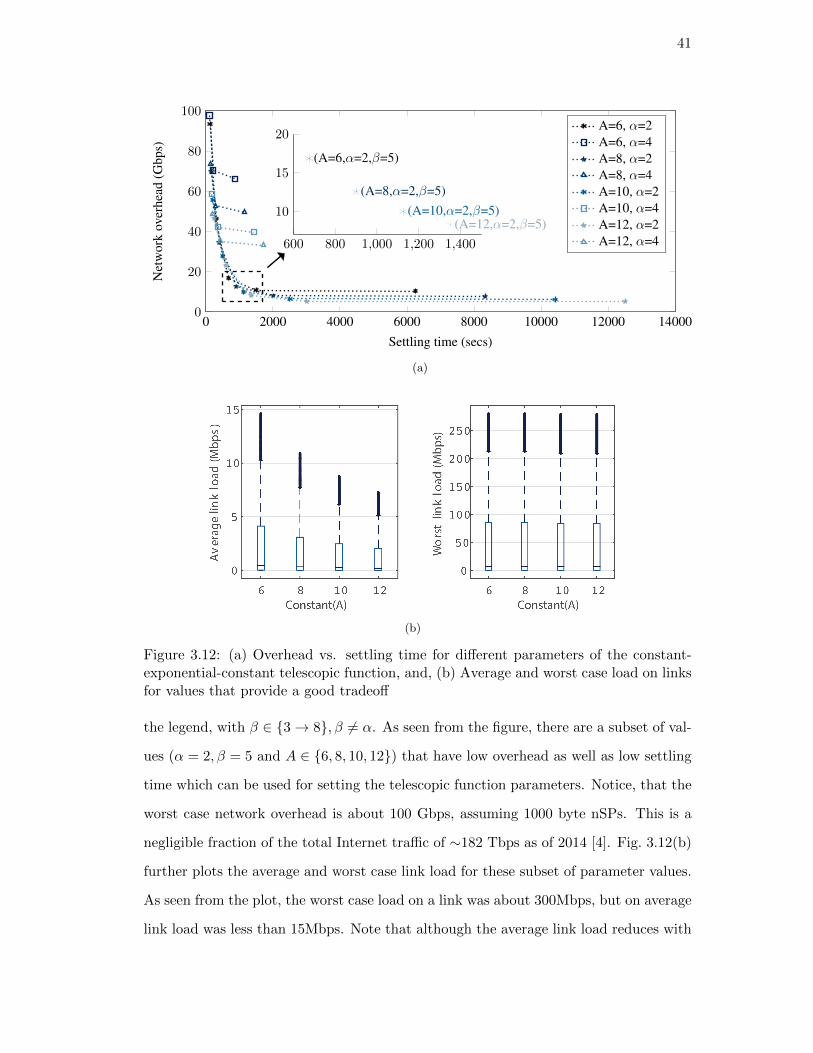
41
0 2000 4000 6000 8000 10000 12000 140000
20
40
60
80
100
Settling time (secs)
Net
wor
kov
erhe
ad(G
bps)
A=6, α=2A=6, α=4A=8, α=2A=8, α=4A=10, α=2A=10, α=4A=12, α=2A=12, α=4600 800 1,000 1,200 1,400
10
15
20
(A=6,α=2,β=5)
(A=8,α=2,β=5)(A=10,α=2,β=5)
(A=12,α=2,β=5)
(a)
(b)
Figure 3.12: (a) Overhead vs. settling time for different parameters of the constant-exponential-constant telescopic function, and, (b) Average and worst case load on linksfor values that provide a good tradeoff
the legend, with β ∈ {3→ 8}, β 6= α. As seen from the figure, there are a subset of val-
ues (α = 2, β = 5 and A ∈ {6, 8, 10, 12}) that have low overhead as well as low settling
time which can be used for setting the telescopic function parameters. Notice, that the
worst case network overhead is about 100 Gbps, assuming 1000 byte nSPs. This is a
negligible fraction of the total Internet traffic of ∼182 Tbps as of 2014 [4]. Fig. 3.12(b)
further plots the average and worst case link load for these subset of parameter values.
As seen from the plot, the worst case load on a link was about 300Mbps, but on average
link load was less than 15Mbps. Note that although the average link load reduces with

42
1
30 35 40 45 50
0
20
40
60
Link failure
Routing update
Stored data
Time(seconds)
Thr
ough
puta
tthe
dest
inat
ion
(Mbp
s)
Figure 3.13: Data delivery to an end-host, with core link failure in EIR
increasing in periodicity of nSP, the worst case link load is almost constant, as the the
latter is based on the instantaneous link load, which is not affected by the periodicity.
Link failure analysis: A key concern for any routing protocol is handling transient
conditions, either due to failures of routers and links or link flapping. To understand the
transient behaviour of EIR, we simulated a vLink failure on a small topology in NS-3,
as highlighted in the bottom-right of Fig. 3.13. In this simulation, a client connected to
NA6 is downloading a large file from a back-end server in NA1. All physical links were
set at 1Gbps with 10 millisecond latency, and each vLink was assumed to be a direct
mapping of the underlying physical link. Each of the NAs shown, are representative of
an aNode in the topology.
Data delivery starts at 30 seconds (assuming the aNode forwarding tables have con-
verged) and the path followed is < server → NA1 → NA2 → NA3 → NA5 → NA6 →
client >. At the 35th second, we simulate failure of the vLink NA5 → NA6. We plot
the throughput at the client per second in Mbps, and as shown in Fig. 3.13, throughput
immediately goes to zero. nSPs are propagated periodically and aNode forwarding ta-
bles are recomputed every time when a new nSP is received. In this experiment, nSPs
are advertised every 5 seconds and therefore, until the 40th second, the information of
the link failure is not propagated in the control plane. MobilityFirst uses a hop-by-hop
reliable transport in the link layer [84], which is particularly beneficial in this case,
since data continues to be pushed towards the destination and gets temporarily stored

43
1/ASsize 1/4 1/3 1/2 2/3 3/4 1
104
105
106
Aggregation fraction
Rou
ting
tabl
esi
ze
EIR table sizeBGP table size
Figure 3.14: Inter-domain table size at each border router for different levels of aggre-gation
at NA5. At the 40th second, NA5 and NA6 both generate a nSP with the updated
vLink information and forward them to their neighbors. On receiving this updated
nSP, NA4 is now able to compute an alternate route, whereas, NA5 also computes the
same alternate route, based on the nSP it receives from NA3. Data delivery therefore
resumes around the 40th second, even though routing tables at NA1 and NA2 have
not converged. Stored data gets rerouted through the alternate path, resulting in a
temporary increase in the client throughput.
This experiment, although simple in essence, highlights two key features of EIR: (i)
Path diversity helps in transient conditions. If EIR followed a traditional BGP style
dissemination approach, the alternate path information would have taken much longer
to be available at the nodes undergoing the link failure; and,(ii) It is not necessary for
every routing table to converge in order to resume data flow, due to the hop-by-hop
store-and-forward delivery approach of MobilityFirst. This is further highlighted in our
network mobility experiment, described later in Section 3.5.2.
Routing table size: Maintenance of a global aNode based topology at each border
router would imply that the inter-domain forwarding table size to be equal to the total
number of aNodes in the topology. In order to investigate the scalability in terms
of routing table entries, we look at a July, 2012 Caida dataset that provides PoP-level
topology of ∼ 22,000 ASes. After parsing for intra and inter-domain links and removing

44
clusters from graph that were not connected (due to incomplete dataset), we evaluated
global routing table size for a graph of 11,340 ASes with their connected PoP topology.
As explained earlier, EIR allows a flexible aggregation scheme, wherein each AS can
independently decide on the number, types and properties of aNodes they wish to
publish in their nSP. We define aggregation as a fraction varying between 1/size and
1, where size is the number of PoPs belonging to that AS. A value of 1/size indicates,
every PoP in an AS is advertised as a separate aNode, whereas a fraction of 1 indicates
an entire AS is a single aNode. A simple case to evaluate would be to consider all ASes
to aggregate uniformly, that is, every AS chooses the same aggregation fraction, which
is shown in Fig. 3.14. In the figure, the blue lines plotted in log scale, show the inter-
domain table size in terms of the number of entries at each border router with varying
levels of aggregation. The red lines show the average BGP table size as reported by
CIDR [85] for the same month and year. Note that although BGP does not provide any
intra-domain topology information, it needs to maintain an entry for every aggregated
address prefix announced in the Internet, which is much larger than the total number
of ASes in the internet. As seen from the plot, even though EIR maintains a global
view of the network, aNode table sizes are comparable to current BGP table sizes, for
moderate levels of aggregation.
In a realistic scenario, we expect ASes to not follow a uniform aggregations scheme
and therefore the table sizes would vary, depending on how many aNodes each AS
advertises. However, if we assume each AS to randomly choose an aggregation fraction,
in the above experiment, on an average, the aggregation fraction would be close to 1/2
and therefore the aNode table sizes will be close to 51K, which is slightly larger than
the corresponding BGP table size. In reality, however, we expect most ISPs to choose
a relatively high aggregation factor and the global table sizes to lie towards the right
of the plot.
Memory requirements: EIR also requires each border router to store the lat-
est copy of the network state packet received from all the other ASes in the network.
As explained earlier in Sec. 3.3.2, each nSP packet size is different, based on the ag-
gregation policies of the source AS and the number of inter-domain neighbors it has.

45
However, assuming a maximum packet length of 4096 bytes (same as the maximum
BGP packet size [33]) and considering the total number of ASes in the network to be
57,840 (as published by CIDR for June 2017 [85]), this would require a memory size
of 4096 × 57840 = 237 MB. Similarly, BGP update packet sizes are also variable and
each peer needs to generate a separate update packet for every unique path. For ex-
ample, for 672,522 destination prefixes (as of June 2017 [85]), there could be as many
as 50,000 unique paths from a peer. While it is difficult to calculate the exact memory
requirements, as Cisco points out, a minimum memory size of 512 MB is recommended
for each BGP router [86] which should also be sufficient for the deployment of EIR.
3.5.2 Prototype evaluation
To measure the performance and implementation feasibility of EIR, we have built a
prototype router (based on the Click modular router design [87]) and evaluated it
using the ORBIT testbed [88]. Our router consists of two components: control plane
and data plane. As shown in Fig. 3.15, border routers send and forward nSPs as per
the specifications outlined in Sec. 3.3.2 through the control plane, whereas internal
routers simply use label based paths set up by the border routers. In addition, all
routers exchange intra-domain link probes and link state updates through the control
plane to build up the intra-domain topology using MobilityFirst’s generalized storage-
aware routing (GSTAR) [28]. GSTAR is a link state routing protocol, where link state
messages carry the estimated time of transmission (ETTs) of intra-domain links. This
in turn is utilized by the border routers in EIR to build aggregated vLinks. Our current
prototype only computes the latency metric of vLinks. In the future, we plan to augment
GSTAR with additional parameters in order to compute bandwidth, availability, and
variability of vLinks.
One of the key aspects of EIR is its support for mobility, both for individual devices
as well as networks as a whole. In order to evaluate such scenarios, we used a realistic
inter-domain topology and a probabilistic mobility transition matrix which is briefly
described below. This was used with the Click software prototype implementation on
the ORBIT testbed for end-user and edge-network mobility evaluations.

46
Figure 3.15: Overview of the Click router prototype for border and internal routers
Topology generation and probabilistic mobility: We start with the previously
described Caida dataset from 2012 with PoP-level topologies, and parse the dataset
based on cities. Specifically we focus on San Francisco, which has a point of presence of
about 326 ASes. We consider a cooperative scheme where a multitude of ASes agree to
share coverage and connectivity among their customers, i.e. a user can decide to switch
from one network provider to another when moving, provided the latter provides a
better coverage in the region. Out of all the available ASes in the dataset, we choose 15
random ASes to participate in this cooperative scheme. Since AS tier information was
not available in the dataset, a random choice ensures that we get a good mix of ASes
from different tiers. Given the PoP-level topology, a corresponding aNode topology is
developed for each of the participating ASes based on geographical proximity, that is,
PoPs belonging to the same AS and located close to each other are clustered to the
same aNode. This lead to a final inter-domain EIR topology of 53 aNodes.
In order to realistically model inter-domain mobility our transition probability ma-
trix takes into account the following factors: (i) Local mobility within a certain radius
(denoted as r), with equal probability of transition to all aNodes within the “local
boundary”; (ii) biased transitions between aNodes belonging to the same AS within
the local boundary, as users tend to remain connected to the same network provider

47
Basic parameters:
Z avg number of network transitions/sec
K total number of network transitions
T granularity of transition (sec)
r avg distance to neighbors (meters)
s avg speed of mobility (m/sec)
w = s/r average transition rate/sec
α probability of transition to a network
Transition probability from node Nj :
α(wT )/Nj to each of Nj ’s neighbors
(1− α)(ZT )/K to each of K non-neighbors
Table 3.2: Probabilistic transition for user mobility
as they move, unless no connectivity by the current provider is available at the new
location; and, (iii) biased transitions (determined by α) to a random, k number of
“macro mobility” points based on the average number of networks visited by a user per
day [89]. Table 3.2 explains the transition probability computations.
Mobility support through late binding: Based on the San Francisco topology
and a mobility matrix generated for a typical mobile user, we looked at the path stretch
that is incurred with and without late binding. Path stretch is defined as the number of
hops traversed by a packet to the number of hops across the shortest path between the
source and the destination. Note that without late binding, failure in delivery would
result in rebinding through a GNRS re-lookup at the previous point of attachment.
On the other hand, late-binding would re-bind the network address at an intermediate
router, as explained in Sec. 3.3.4. The late-binding algorithm for this evaluation chooses
the aNode with the highest degree along the path as the late-binding point. The
intuition behind this logic is that a highly connected node would have shorter path
stretch to the next point of association for the user.
Fig. 3.16 highlights the improvement in path-stretch when packets are late binded
along the way. Notice that the solid blue and the dotted red curves are fairly close since
once a mobile node moves, only the packets in transit are rerouted and suffer a path
stretch, whereas newer packets are automatically sent to the new destination, from the
source, following a GNRS lookup. Also note that MobilityFirst data packets carry both
the GUID and the network address in its header [26]. Therefore, lookups do not need

48
1 1.05 1.1 1.15 1.2 1.25 1.3 1.35 1.40
0.2
0.4
0.6
0.8
1
Path stretch
CD
F
No late bindingLate binding at an intermediate aNode
Figure 3.16: CDF of path stretch with and without late binding for end-user mobility
to be done at every aNode. Once a lookup is done, the up-to-date address is reflected
in the packet to reduce further lookups. GNRS responses can also be temporarily
cached at a router such that subsequent packets do not need a lookup. However, in
our experiment, every packet incurred a GNRS server (located 1 hop away) lookup
roundtrip delay. Previous works have looked at how to distribute GNRS servers in
order to further reduce this lookup latency [24,25].
In future evaluations, we plan to look at different late binding techniques, so as
to minimize path-stretch and improve latency of data delivery across a broad range of
mobility scenarios.
Network mobility: Based on the same topology, we evaluate a network mobility
use-case, where the evaluation scenario consists of a mobile aNode connecting to differ-
ent ASes as it moves and a source in a distant AS trying to deliver data to the mobile
network. To realistically model network mobility, we use actual bus traces from San
Francisco Municipal Transit system [90]. We measure the data delivery failure rate for
different routing update rates, where failure rate is defined as the ratio of number of
packets not received to the number of packets sent. Since rebinding and delay tolerant
delivery are supported by the MobilityFirst architecture, packets will eventually be de-
livered at any mobile node. For the purpose of this experiment, we calculate failure at
the previous point of association, before packets are rerouted to the next.
Fig. 3.17 shows the delivery rate at mobile buses on 9 randomly picked routes,

49
1 2 3 4 5 6 7 80
1
2
3Inter-domain update interval, t = f(A)
Bus ID
Data
undergoing
temporary
storage(%
)A=4A=6A=8
Figure 3.17: Data delivery failure rate for different telescopic update intervals for net-work mobility
for different update intervals of the telescopic function. Similar to our previous experi-
ments, the values of α and β were kept constant at 2 and 5 respectively as they provided
reasonable overhead and settling time, based on our Internet-scale simulation. We also
looked at the number of AS transitions for each trace which determines the failure rate
and observed that 2 hops AS transition tend to dominate these mobility events. Of the
9 randomly picked traces, trace 1 resulted in a scenario that had primarily 1-hop tran-
sitions and hence the data delivery rate is almost similar for different telescopic hold
time. Whereas in the other traces, there are a few transitions to ASes that are multiple
AS-hops away. Consequently, the failure rate increases with the telescopic parameter,
A as the reachability to the mobile aNode is not known for a longer period of time due
to the telescopic hold function of the nSPs.
3.6 Related Work
There has been a considerable amount of work done in improving inter-domain routing
which can be broadly classified into two categories: (1) extensions to BGP, and (2)
clean-slate routing proposals.
Extensions to BGP: Proposals such as path splicing [91] and route-deflections [92]

50
are loose source routing based schemes, where the end-hosts are assumed to be intelli-
gent enough to decide and to explicitly choose a path alternative to the default BGP-
computed route. [92] provides a limited choice of paths, whereas [91] provides path
diversity, but does not address the issue of scalability. MIRO [80] moves the decision of
path choice from the end-host to the AS which could request alternate paths if it is not
satisfied with the default BGP route. This handles scalability effectively, but reduces
path diversity. The authors in [93] propose similar fail-over path set-up techniques in
order to reduce disconnections on link failures. In contrast, the authors of Intelligent
Route Service Control Point (IRSCP) [94] propose a service plane with active servers
that act in conjunction with BGP in order to perform dynamic route control, which
requires additional resources and results in increased control overhead.
Recent works on BGP, have introduced the mechanism of advertising multiple paths
for the same address prefix [95] as well as defining and advertising multiple classes of
services (CoS) [69]. Multipath BGP [95] is akin to the EIR design choice of adver-
tising multiple paths in each AS. However, EIR goes one step farther by providing
path diversity in the form of aggregated intra-domain routes as well. The concept of
advertising multiple CoS in EQ-BGP [69] is also similar in spirit to EIR’s SID space.
In this design however, there is no concept of multiple paths being advertised for each
CoS. The authors propose to extend BGP reachability messages to include CoS infor-
mation of each AS. Q-BGP [96] proposes the same ideas as EQ-BGP but by defining
new update messages to disseminate QoS classes. In EIR, we have adopted the former
design choice, in order to keep the routing control overhead tractable. In this respect,
EIR design is conceptually a union of EQ-BGP (multiple service classes) and MP-BGP
(path diversity).
Clean slate routing: There has also been a growing interest in the Internet com-
munity to look for alternatives of BGP that could be incrementally deployed. For
example, in the locator-identifier split approach (LISP) [8], tunnels are set up between
egress points in an AS, similar to MPLS [68], and then BGP is used to deliver data
based on these tunnels. A flat end-point ID is then used at the receiving AS to deliver
to the final destination. This multi-AS tunnel setup could easily be emulated in EIR,

51
with the difference being that tunnels and end-hosts are both identified by flat GUIDs.
In addition, intra-AS aNode-level topology information provides a finer granularity of
path selection in case of EIR. As mentioned before, the aNode-vLink abstraction in
EIR is similar to the idea of vNodes in Pathlet [59]. Recent standardization efforts
have looked into segment routing [97] which also proposes abstracting the network into
segments and then choosing appropriate segments at the source to build and end-to-end
path. However, our path-selection approach is quite different from Pathlet and segment
routing, both of which perform loose source routing. Instead, EIR provides the flexibil-
ity to choose end-to-end routes to both end-hosts as well as intermediate ASes through
the use of SIDs. EIR also utilizes the name resolution service (GNRS) of MobilityFirst
to perform dynamic rerouting of in-transit packets during mobility and changing net-
work conditions, which is difficult to do in source-based routing. HLP [98] uses a hybrid
link-state and path-vector approach where provider-customer sub-graphs use link-state
routing for path-diversity and peers use path-vector. This effectively improves scala-
bility of the protocol. In contrast providing a global view of multiple end-to-end paths
provides additional path-diversity and allows EIR to realize policies beyond simple busi-
ness relationships. NIRA [79] offers more choice to end-users in choosing the exact set
of transit ASes using a hierarchical provider-rooted address scheme. However, similar
to HLP, the basic protocol provides limited support for policies other than business
relationships.
3.7 Summary
In this chapter, we have proposed the edge-aware inter-domain (EIR) routing protocol
as a potential solution for inter-network routing in the future mobile Internet. The
proposed architecture has been shown to provide improved support and flexibility for
routing to wireless devices, network-assisted multipath routing, routing to multiple in-
terfaces (multi-homing) and service anycast. Our results show that even with increased
expressiveness of network structure and node/link properties, the protocol can be de-
signed to have reasonably small overhead via telescopic dissemination of the nSPs.

52
Further, prototype evaluations of the protocol using Click software routers on the OR-
BIT testbed were conducted to show proof-of-concept level feasibility. Experimental
results for selected use-cases show good service level performance can be achieved in
highly mobile scenarios.

53
Chapter 4
Named Object Multicast
4.1 Introduction
Internet applications like video streaming, online gaming and social networks, e.g. Twit-
ter, often require dissemination of the same piece of information to multiple consumers
at the same time. While multicast routing protocols have long been available, most of
these applications rely on unicast based solutions that exploit overlay networks aimed
at improving the efficiency of pushing the required data without support from the net-
work. Recent increases in network traffic associated with the growth of mobile devices,
Internet-of-Things (IoT) devices, smart wearables and connected vehicles, motivate the
need for efficient push multicast, a service that is not well-addressed through overlay
solutions. Consider for example IoT based messaging scenarios: a typical query involves
sending short messages to hundreds or thousands of users or application agents, so that
scalability becomes an issue, as multiple unicast messages through an overlay service can
easily overload the network. Mobility of end-devices results in additional complexity,
especially for dynamic environments such as vehicular communications. For example,
if a single warning message needs to be pushed to hundreds of cars and pedestrians in
a given area, multicast groups would need to be maintained across a large number of
access networks in order to efficiently support such one-to-many communication.
Using appropriate multicast routing solutions would help solve these problems by
improving network efficiency, while reducing the complexity and cost of deploying such
applications. However, existing network-layer multicast solutions (e.g., PIM-SM [99],
MOSPF [100]) have not been widely adopted due to fundamental problems that are
a by-product of the original Internet design geared toward static host-centric commu-
nication. These solutions implicitly couple the forwarding path (location) with the

54
Application Multicast Type Group Size Group Flux Longevity Flow Size
IoT commands Push 1000’s Hours Days KB-MB
Accident notification Push 100’s Seconds Minutes KB
Twitter Pull 100’s of 1000 Minutes Months KB-MB
IPTV Pull 1000’s Relatively static Months GB
Multiplayer games Push/Pull 100’s Hours Hours GB
Table 4.1: Emerging multicast application and their characteristics
multicast group (name). Whenever a receiver moves to a new location, it has to rejoin
the multicast tree it was previously a part of and the network has to change the tree
structure accordingly. This can cause packet loss during the process and large amount
of distributed control traffic is generated to modify the tree structure. The problem
becomes particularly acute for applications like Twitter where each receiver might have
more than 100 groups to join each time it moves. Secondly, extending these protocols
to inter-domain has achieved mixed results, with issues of scalability and coordination
across domains [101]. For example IP multicast based on PIM-SM [102] relies on ren-
dezvous points (RPs) as the shared root of a tree. However domains are often unwilling
to have RPs for their local groups to be maintained in other domains. This leads to
having RPs in every domain connected in a loose mesh, that require periodic flooding
of control messages for coordination and management. Multicast group address assign-
ment may require a separate protocol altogether, such as the Multicast Address-Set
Claim (MASC) protocol used in conjunction with BGMP [103]. All of these problems
have negative consequences for highly dynamic environments and emerging application
scenarios. For example, in the vehicular use-case previously described, group member-
ship changes rapidly with vehicular mobility. In addition, the context of data-delivery
may change with time as well. An accident or traffic-alert push-notification to a group of
cars in NJ Turnpike is such an example. Table 4.1 describes a sample set of application
scenarios that require efficient multicast primitives and their characteristics.
Application layer solutions for multicast have also been explored in this context;
works like SCRIBE [104] and ZIGZAG [105] sought to find scalable and efficient solu-
tions by building an overlay among the receivers in a tree or mesh structure. These
solutions do address mobility and inter-domain management issues, but due to the lack

55
of topology awareness, they may incur high levels of network traffic. In addition, forcing
the end hosts to replicate packets, instead of dedicated routers results in heavy workload
on the end hosts, which may have intrinsic power and computation constraints.
Based on the above considerations, a native network layer multicasting solution is
identified as an important goal for future networks which are increasingly required to
support many-to-many communication modes. We propose a solution based on named
objects and a dynamic name-resolution service for mapping names to routable network
entities, as described earlier in Chapter 2. Separating names (identities) from addresses
has been advocated by the research community [7, 23, 26] for quite some time and has
inherent benefits in handling mobility and dynamism for one-to-one communication.
But they also provide additional advantages by facilitating creation of new service
abstractions that can be used to design solutions for multicast services. First, names can
be used to represent many different Internet objects and therefore it perfectly applies
to the context of multicast to define a group of participating end-hosts. Moreover, new
entities can be integrated within these names, not being constrained to end points;
through this, we gain the ability to directly refer to network entities that actively
participate in the formation of a multicast tree, such as routers that implement the
multicast routing protocols.
We exploit names to design a Named Object Multicast (NOMA) solution which relies
on separation of names and addresses using a globally distributed, logically centralized
name resolution service, similar in spirit to an evolved DNS. In NOMA each multicast
group is identified by a unique name across all domains, thus separating routing logic
from group management. NOMA takes advantage of the dynamic name resolution
service to manage the tree, using name recursion, to store the tree topology. This is
achieved by mapping unique names assigned to participating routers to their children
nodes, as shown in Fig. 4.1. Data forwarding is then performed using tunnels between
participating nodes; end-to-end information is preserved within the packet, while the
information globally available in the name resolution service is used to identify next
hops in the distribution path allowing for quick branching and replicating decisions.
Finally, dynamicity of mobile environments is handled by decoupling the participants

56
Figure 4.1: Hierarchical tree structure maintained in a name resolution service, withnames of tree nodes recursively mapping to routable addresses
name from their location through the resolution service and periodically recomputing
the multicast tree; the system first needs to translate the name into a list of host
names participating in the multicast group. The routable address (locator) of each
host (whether mobile or static) can then be identified by a subsequent query to the
name resolution service.
The remainder of the chapter provides the details of our design and performance
evaluation of the proposed scheme which include:
• The design of NOMA architecture that leverages use of names and global name
resolution service to manage multicast routing protocols;
• An efficient centralized tree-construction mechanism that minimizes the network
traffic with relatively low computational overhead; and
• Large-scale simulations to demonstrate the reliability, efficiency and scalability of
NOMA design even when there is node mobility.

57
4.2 NOMA Design
NOMA aims to achieve efficient multicast communications through the employment
of a logically centralized, globally distributed name resolution service associated with
name based communications. In order to explain NOMA’s design, we utilize a Global
Name Resolution Service (GNRS) as a network-wide entity that provides an API for
inserting and querying mappings between unique name identifiers and a set of values
which can include network addresses, other name identifiers and related parameters –
e.g. node properties, past locations and more. In spirit, this service is very similar
to current Internet’s DNS, which has already been effectively applied for new service
functions such as load balancing and service replication. Even more interesting services
can be realized with the next generation of global name resolution services such as
DMap [24] and Auspice [25] introduced recently. The key advantage of using a name
resolution service is to achieve a clean separation of network names from addresses.
NOMA’s design, as proposed here, is based on MobilityFirst (MF [26]), which
is a clean-sate network architecture for the next-generation mobile network where
DMap [24] is used to provide resolution of names, that are Globally Unique Identi-
fiers (GUIDs), into routable network addresses (NAs). Moreover, MF incorporates a
hybrid name-address forwarding scheme, in which routing components use availability
of both names and addresses in packet headers to perform forwarding decisions. Note
that even though NOMA is based on MF, the same design concept can be applied to IP
extensions (such as HIP [7]), overlay protocols (such as SCRIBE [104]), or clean-slate
ICN protocols such as NDN [36] and XIA [37] through the use of a similarly designed
name resolution service.
4.2.1 Multicast Tree Management
Multicast management consists of two core operations: membership of destination
nodes and building and management of multicast trees. Both operations can be stream-
lined by exploiting the logically centralized, globally distributed, name resolution ser-
vice (GNRS); in particular by using two forms of name indirection. A first unique
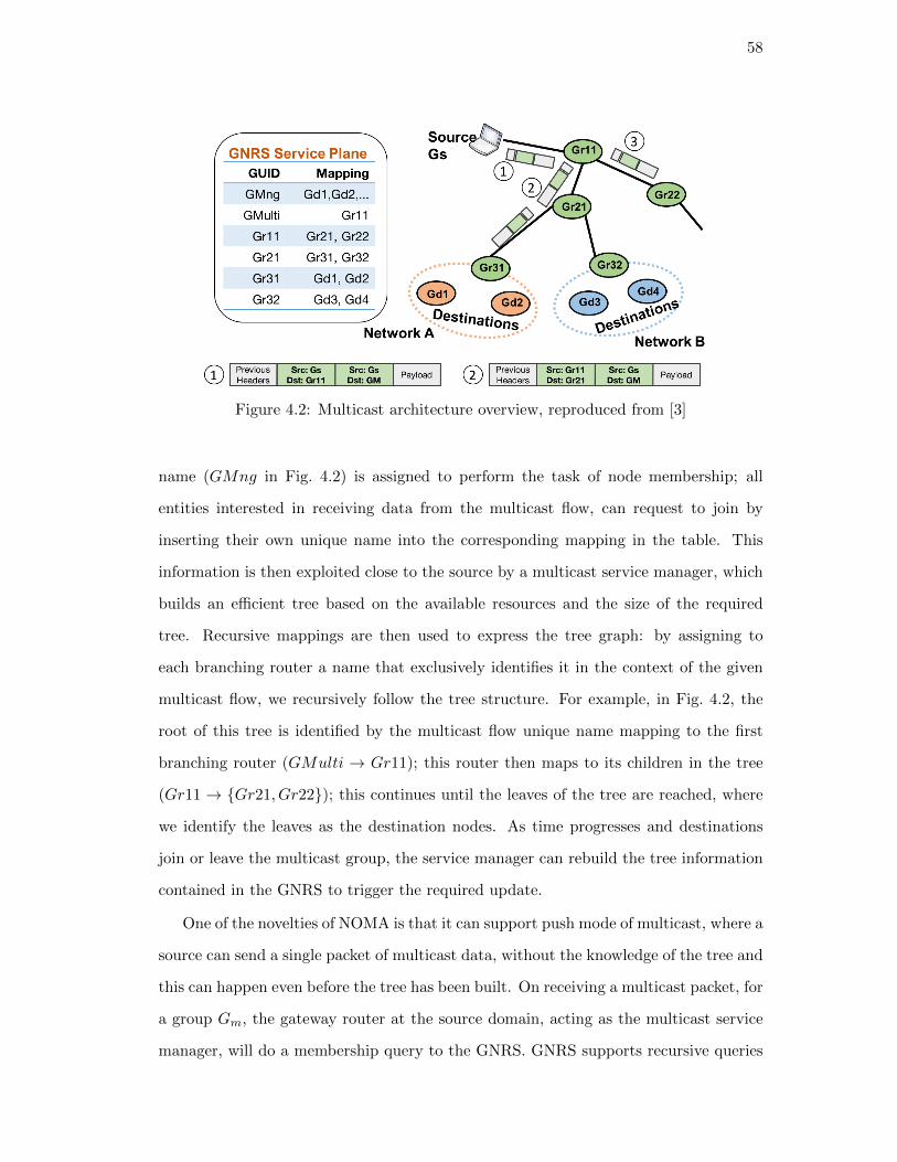
58
Figure 4.2: Multicast architecture overview, reproduced from [3]
name (GMng in Fig. 4.2) is assigned to perform the task of node membership; all
entities interested in receiving data from the multicast flow, can request to join by
inserting their own unique name into the corresponding mapping in the table. This
information is then exploited close to the source by a multicast service manager, which
builds an efficient tree based on the available resources and the size of the required
tree. Recursive mappings are then used to express the tree graph: by assigning to
each branching router a name that exclusively identifies it in the context of the given
multicast flow, we recursively follow the tree structure. For example, in Fig. 4.2, the
root of this tree is identified by the multicast flow unique name mapping to the first
branching router (GMulti → Gr11); this router then maps to its children in the tree
(Gr11 → {Gr21, Gr22}); this continues until the leaves of the tree are reached, where
we identify the leaves as the destination nodes. As time progresses and destinations
join or leave the multicast group, the service manager can rebuild the tree information
contained in the GNRS to trigger the required update.
One of the novelties of NOMA is that it can support push mode of multicast, where a
source can send a single packet of multicast data, without the knowledge of the tree and
this can happen even before the tree has been built. On receiving a multicast packet, for
a group Gm, the gateway router at the source domain, acting as the multicast service
manager, will do a membership query to the GNRS. GNRS supports recursive queries

59
Figure 4.3: Tree building steps comparison of NOMA with IP multicast
that return the host GUIDs along with the NAs of the domains they are currently
connected to. Having the service manager on the gateway enables the tree computation
to be topology-aware, as unicast path information of the NAs is available at the gateway,
which is then used to build the tree. Once a tree is computed, it is updated in the
GNRS such that downstream nodes do not need to recompute the tree again. This is
quite different than distributed tree management techniques used in IP multicast since
NOMA does not require flooding of multicast control messages (for example, source
active (SA) or Join messages in PIM-SM and MSDP [102]) across domains, as shown in
Fig. 4.3. The latter limits the scalability for traditional multicasting techniques to small
to medium groups, as shown later in Sec. 4.3. Also, using unique names to represent
a group, members of the group as well as the multicast tree eliminates the need of
a separate address allocation protocol, similar to MASC required for BGMP [103].
For evaluation purposes, we focused on two categories of multicast tree computation
algorithms, i.e. shortest path trees (SPTs) and Steiner trees. A constraint of having
centralized computation of trees is complexity and hence we opted for SPT and its
modifications, even though our design is not limited to any specific algorithm.
4.2.2 Data Forwarding
Once the multicast tree is established, data forwarding can exploit the information
contained in the GNRS to efficiently flow through edges between the nodes of the tree.
In order to do so, we exploit address encapsulation, where two pieces of information

60
are carried in data packets at the same time: Internally (i.e. second field in the green
packets in Fig. 4.2), the encapsulated information carries the source and destination
of the multicast flow, providing valuable information usable by all nodes along the
path to easily identify data streams. Externally, routing information to perform hop-
by-hop forwarding from one branching node to the next is placed. At each branching
node participating in the multicast, forwarding decisions are performed by querying the
GNRS to obtain information on how many next hops it has to forward to, generating
required duplicates and replacing the external routing information with the new hop
source and destination; this process is exemplified in the figure, where node Gr21
generates 2 duplicates for its two children, replacing headers accordingly. Intermediate
nodes along the path forward encapsulated packets based on normal unicast rules. This
reduces complexity of multicast packet processing to only a subset of nodes of the tree.
To reduce the need of continuously involving the GNRS in the forwarding procedure,
mappings can be cached at each hop, avoiding traffic and computational overhead. The
tradeoff for this approach comes at the cost of slower reaction times to tree change
events. More details on how to handle tree restructuring and end points mobility is
provided in the following section.
4.2.3 Handling Mobility:
End host mobility support has been a challenging problem in both unicast and multicast
delivery. For the latter, the situation is further aggravated by the fact that an end-host
mobility can significantly alter the multicast tree and hence its efficiency of delivery
to other connected end-hosts. Without a clean separation of names and addresses, the
onus of re-booting an ongoing session falls on to the mobile end-host. For an inter-
domain multicast delivery, this means that every time an end-host moves and changes
its point of association, it needs to send an explicit join at the new point of connectivity.
The router at the new domain will then need to join the multicast tree, before the end-
host can receive any data. Meanwhile, following a best-effort delivery policy, all the
data received at the previous point of association will be lost.
NOMA on the other hand handles mobility by separating names from addresses and

61
Figure 4.4: Device mobility handling through unicast repair messages
maintaining a name-based tree in the GNRS. At any point of the tree, failure in delivery
to a downstream node results in temporary storage of data packets (MF routers are
storage-capable [28]) and re-querying the GNRS for an up-to-date downstream node
name (GUID) to its address (NA) mapping. This is specially relevant for the leaves of
the tree which could be mobile end-hosts. As mentioned earlier for a long-lived flow
tree, restructuring takes place periodically and any mobility that happens at a faster
time-scale than tree re-computation will suffer. In order to ensure that end-hosts do not
lose packets while moving, NOMA supports encapsulated ‘repair’ packets to be sent to
the moving client. This again is enabled by the GNRS that maintains the up-to-date
location (end-host GUID to NA mapping) as it moves. As shown in Fig. 4.4, when a end-
host D1 moves from NA14 to NA11, which is not part of the multicast distribution
tree, the tree does not change immediately. However, failure to deliver at the edge,
causes the gateway router at NA14 to query the GNRS for up-to-date mapping of D1.
Following association at NA11, the gateway at NA14 can encapsulate the pending data
and send it as unicast repair to NA11 as shown. In contrast to multicasting, the repair

62
procedure is transparent to an end-host or application and does not require explicit
re-joining from the client side. However this is only a short-term mechanism to counter
moderate mobility of a subset of destinations. With increase in the number of devices
and mobility, the frequency of tree updates should increase proportionally.
4.3 Evaluation
In this section we present detailed performance evaluation based on a combination
of large scale analytical modeling and fine-grained packet-level simulation on network
simulator (NS3).
4.3.1 Tree Generation Algorithms
NOMA provides a framework for managing and deploying multicast communications,
independently from the tree generation algorithm employed. While this is a valuable
feature of the design, it is necessary to study different algorithms and heuristics in the
context of choosing one that can effectively utilize unicast routes, and is lightweight
enough to be able to run at a single router. We looked at two main categories of algo-
rithms for building multicast trees, namely shortest path trees (SPTs) and Steiner trees.
Although Steiner trees provide an optimal solution in terms of overall network resource
utilization, they are NP-hard to compute. Several Steiner heuristics have been proposed
over the years to provide near-optimal solutions [106], with relatively high computa-
tion cost. However, computational complexity is a key constraint for our design, since
the tree computation is centralized. We instead opt for the SPT algorithm that uses
inter-domain unicast route information and require no further computation, but is less
efficient compared with a Steiner tree. In SPT, packets are forwarded along the longest-
common path (LCP) to all the destinations, as single copy, until the branching point is
reached, where the packet is copied and delivered towards multiple destinations. This
allows all destinations to receive multicast packets across the shortest path from the
source. We also analyzed other heuristics that aimed to further minimize the overall
network traffic with moderate computation. One of these heuristics is the look-ahead
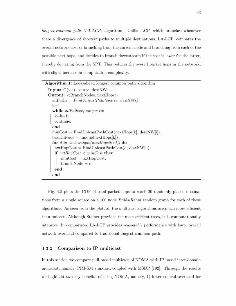
63
longest-common path (LA-LCP) algorithm. Unlike LCP, which branches whenever
there a divergence of shortest paths to multiple destinations, LA-LCP, compares the
overall network cost of branching from the current node and branching from each of the
possible next hops, and decides to branch downstream if the cost is lower for the latter,
thereby deviating from the SPT. This reduces the overall packet hops in the network,
with slight increase in computation complexity.
Algorithm 1: Look-ahead longest common path algorithm
Input: G(v,e), source, destNWsOutput: <BranchNodes, nextHops>
allPaths = FindUnicastPath(source, destNWs)k=1while allPaths[k].unique dok=k+1;continue;
endminCost = FindUnicastPathCost(nextHops[k], destNW[i]) ;branchNode = unique(nextHops[k]) ;for d in each unique(nextHops[k+1]) donxtHopCost = FindUnicastPathCost(d, destNW[i]);if nxtHopCost < minCost then
minCost = nxtHopCost;branchNode = d;
end
end
Fig. 4.5 plots the CDF of total packet hops to reach 20 randomly placed destina-
tions from a single source on a 100 node Erdos-Renyi random graph for each of these
algorithms. As seen from the plot, all the multicast algorithms are much more efficient
than unicast. Although Steiner provides the most efficient trees, it is computationally
intensive. In comparison, LA-LCP provides reasonable performance with lower overall
network overhead compared to traditional longest common path.
4.3.2 Comparison to IP multicast
In this section we compare pull-based multicast of NOMA with IP based inter-domain
multicast, namely, PIM-SM standard coupled with MSDP [102]. Through the results
we highlight two key benefits of using NOMA, namely, 1) lower control overhead for

64
1
20 25 30 35 40 45 50 55 600
0.2
0.4
0.6
0.8
1
total # of packet hops
CD
F
SteinerLongest common path (LCP)Look-ahead LCP (LA-LCP)Unicast
Figure 4.5: CDF of total packet hops in terms of packet hops for different multicast treegeneration algorithms, for 100 node random graph with 20 randomly chosen destinationnodes.
maintaining a multicast group, and 2) better handling of mobility for data forwarding.
Note that BGMP [103] is another prominent inter-domain IP multicast scheme, how-
ever, it is not well-suited for applications that involve dynamism and fast changes in
the tree, and hence has not been a focus of our evaluation. BGMP allows multicast
route updates to be carried along with inter-domain BGP messages and therefore tree
changes occur at a much slower time-scale than PIM-SM/MSDP (typical BGP updates
take about 100 seconds to propagate throughout the network [107]). These set of results
have been previously published in our work available at [108].
• Control overhead: The advantage of using unicast routes to build the tree
is that no multicast specific control overhead needs to be exchanged across networks.
This is crucial for inter-domain settings where flooding periodic multicast tree update
messages is not tractable. In Fig. 4.6 we plot the multicast specific messages exchanged
for setting up a tree and forwarding packets for increasing graph sizes, with the topology
being an Erdos-Renyi random graph, and 50% of the nodes being randomly chosen to
have destination clients part of the multicast group. For NOMA this includes 1) the
GNRS insert messages from each of the destination networks for joining a particular
multicast group, 2) the GNRS insert from the gateway at the source domain to insert the
generated multicast tree, and, 3) GNRS query and responses during data forwarding at
the branching nodes. The GNRS is implemented as a distributed hashmap, following the
DMap design [24], with the same mapping stored at multiple locations. For evaluation

65
1
20 50 100 10000
2
4
6
8
10
12·104
Graph Size
Ave
rage
pack
etho
ps
NOMAPIM-SM+MSDP
20 50 1000
500
1,000
Figure 4.6: Control packet overhead for tree setup for varying graph sizes
purposes, 3 GNRS instances were maintained, therefore each insert incurred 3 unicast
messages to 3 specific nodes (determined by a hash function), whereas each query was
anycasted to the nearest of the 3. In comparison, for PIM-SM+MSDP the overhead
numbers comprise of, 1) the flooding of Source-Active (SA) messages from the source
domain throughout the network, and, 2) the Join messages from the domains which
have destinations nodes interested in receiving packet from that particular source. As
seen from the plot, maintaining a multicast tree in the GNRS has higher overhead for
smaller sized graphs (for example, for a 20 node topology, shown in the zoomed in
section of Fig. 4.6), but it scales elegantly with size. Using PIM-SM+MSDP, on the
other hand, becomes intractable as the number of nodes increases. With more than
40 thousand ASes in the Internet today, if every domain was multicast enabled, the
cost becomes too high to maintain a distributed tree. Similar trends were observed
by varying percentage of destination networks for fixed graph sizes and is not included
here for brevity.
• Handling mobility: NOMA seamlessly handles client mobility and the dy-
namism in tree-changes thereof, by periodically recomputing the tree and updating
the corresponding GNRS entries. In addition, to counter packet-loss due to mobility,
NOMA supports unicast ‘repair’ packets to be sent from a previous edge node to the
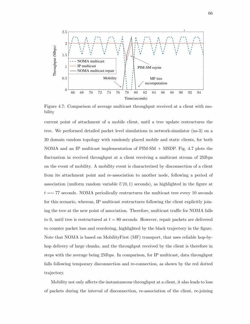
66
1
66 68 70 72 74 76 78 80 82 84 86 88 90 92 940
0.5
1
1.5
2
2.5
Time(seconds)
Thr
ough
put(
Mbp
s)
NOMA multicastIP multicastNOMA multicast repair
Mobility MF treerecomputation
PIM-SM rejoin
Figure 4.7: Comparison of average multicast throughput received at a client with mo-bility
current point of attachment of a mobile client, until a tree update restructures the
tree. We performed detailed packet level simulations in network-simulator (ns-3) on a
20 domain random topology with randomly placed mobile and static clients, for both
NOMA and an IP multicast implementation of PIM-SM + MSDP. Fig. 4.7 plots the
fluctuation in received throughput at a client receiving a multicast stream of 2Mbps
on the event of mobility. A mobility event is characterized by disconnection of a client
from its attachment point and re-association to another node, following a period of
association (uniform random variable U(0, 1) seconds), as highlighted in the figure at
t =∼ 77 seconds. NOMA periodically restructures the multicast tree every 10 seconds
for this scenario, whereas, IP multicast restructures following the client explicitly join-
ing the tree at the new point of association. Therefore, multicast traffic for NOMA falls
to 0, until tree is restructured at t = 80 seconds. However, repair packets are delivered
to counter packet loss and reordering, highlighted by the black trajectory in the figure.
Note that NOMA is based on MobilityFirst (MF) transport, that uses reliable hop-by-
hop delivery of large chunks, and the throughput received by the client is therefore in
steps with the average being 2Mbps. In comparison, for IP multicast, data throughput
falls following temporary disconnection and re-connection, as shown by the red dotted
trajectory.
Mobility not only affects the instantaneous throughput at a client, it also leads to loss
of packets during the interval of disconnection, re-association of the client, re-joining
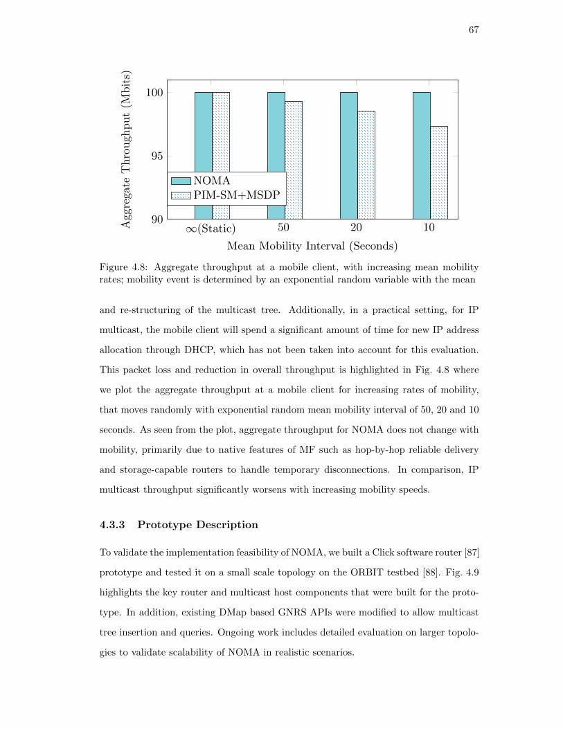
67
∞(Static) 50 20 1090
95
100
Mean Mobility Interval (Seconds)
Aggrega
teThroughput(M
bits)
NOMAPIM-SM+MSDP
Figure 4.8: Aggregate throughput at a mobile client, with increasing mean mobilityrates; mobility event is determined by an exponential random variable with the mean
and re-structuring of the multicast tree. Additionally, in a practical setting, for IP
multicast, the mobile client will spend a significant amount of time for new IP address
allocation through DHCP, which has not been taken into account for this evaluation.
This packet loss and reduction in overall throughput is highlighted in Fig. 4.8 where
we plot the aggregate throughput at a mobile client for increasing rates of mobility,
that moves randomly with exponential random mean mobility interval of 50, 20 and 10
seconds. As seen from the plot, aggregate throughput for NOMA does not change with
mobility, primarily due to native features of MF such as hop-by-hop reliable delivery
and storage-capable routers to handle temporary disconnections. In comparison, IP
multicast throughput significantly worsens with increasing mobility speeds.
4.3.3 Prototype Description
To validate the implementation feasibility of NOMA, we built a Click software router [87]
prototype and tested it on a small scale topology on the ORBIT testbed [88]. Fig. 4.9
highlights the key router and multicast host components that were built for the proto-
type. In addition, existing DMap based GNRS APIs were modified to allow multicast
tree insertion and queries. Ongoing work includes detailed evaluation on larger topolo-
gies to validate scalability of NOMA in realistic scenarios.

68
Figure 4.9: Components of the NOMA router prototype, GNRS and client implemen-tation, with developed modules shown in blue
4.4 Summary
In this chapter, we have proposed a name based inter-domain multicast approach,
leveraging on a distributed name resolution service for membership and tree manage-
ment. The proposed NOMA framework scales reasonably well to medium to large scale
trees and handles client mobility with disconnections. Large scale analytical results for
management overhead and fine-grained packet-level simulations for mobility scenarios
were provided. In addition, we presented a proof-of-concept prototype with small-scale
experiments as feasibility studies.

69
Chapter 5
Comparison to Alternative Name-based Architectures
5.1 Introduction
Two key elements define the named-object abstraction: the name to location separation
and the ability to identify the requested service for in transit data. To understand
the benefits of the abstraction in supporting advanced mobility services, this chapter
provides a qualitative analysis of the named-object based architecture, MobilityFirst
against three classes of alternate approaches: one that employs no resolution via pure
name based routing (using CCN as an example) and two that provide the name/location
separation via end-host based resolution (HIP) or using a Name Resolution Service
(LISP), but that do not incorporate service identification. While for certain services
the name/location separation is sufficient and no differentiation will be given between
the LISP and MF, more advanced scenarios will show how the second component can
provide additional value supporting the case for named-objects. The comparison focuses
on three key services: mobility (Fig. 5.1), multihoming support (Fig. 5.2) and multicast
delivery (Fig. 5.3).
5.1.1 Handling Mobility
Pure name based routing architectures require no resolution of names to addresses
since routing is also based on names. While this is an interesting paradigm, having an
immutable name with no location information whatsoever implies every time a device
moves, routing updates need to be flooded, such that the rest of the Internet can build
a new route to this name. For architectures with hierarchical names, such as CCN [21],
there can be some control on the flood based on name aggregation. However, with
networks becoming smaller and denser and entities becoming more mobile, frequent

70
Figure 5.1: Mobility management techniques: pure name based, end-host based andNRS based
mobility with handoffs is becoming a norm. As shown in [109], with 10 billion mobile
devices worldwide, issuing routing updates for every single mobility event is not scalable.
End-to-end mobility management techniques name devices with permanent iden-
tifiers but route based on locators, which change at a much slower time scale than
host-mobility. Therefore, for every mobility event, there is an end-to-end messag-
ing/handshaking between the mobile end-points to notify their routing locator. This
works for scenarios where one of the end-points is relatively static; if Name X knows
the locator of Name Y (in this case Loc C ) apriori, it can initiate the hand-shaking
mechanism. However, if both the end-points are moving simultaneously, there needs to
be an additional service or a rendezvous server, which has a fixed known locator. The
end-devices need to communicate with this server which then brokers the handshaking
between the two [110].
Instead of making end-points responsible for mobility management, the Name Res-
olution Service (NRS) and named-object based approaches deploy a distributed infras-
tructure, that maps names of objects to their current locators [26, 111]. As mobile
devices move, they update the resolution system with their up-to-date locator and any
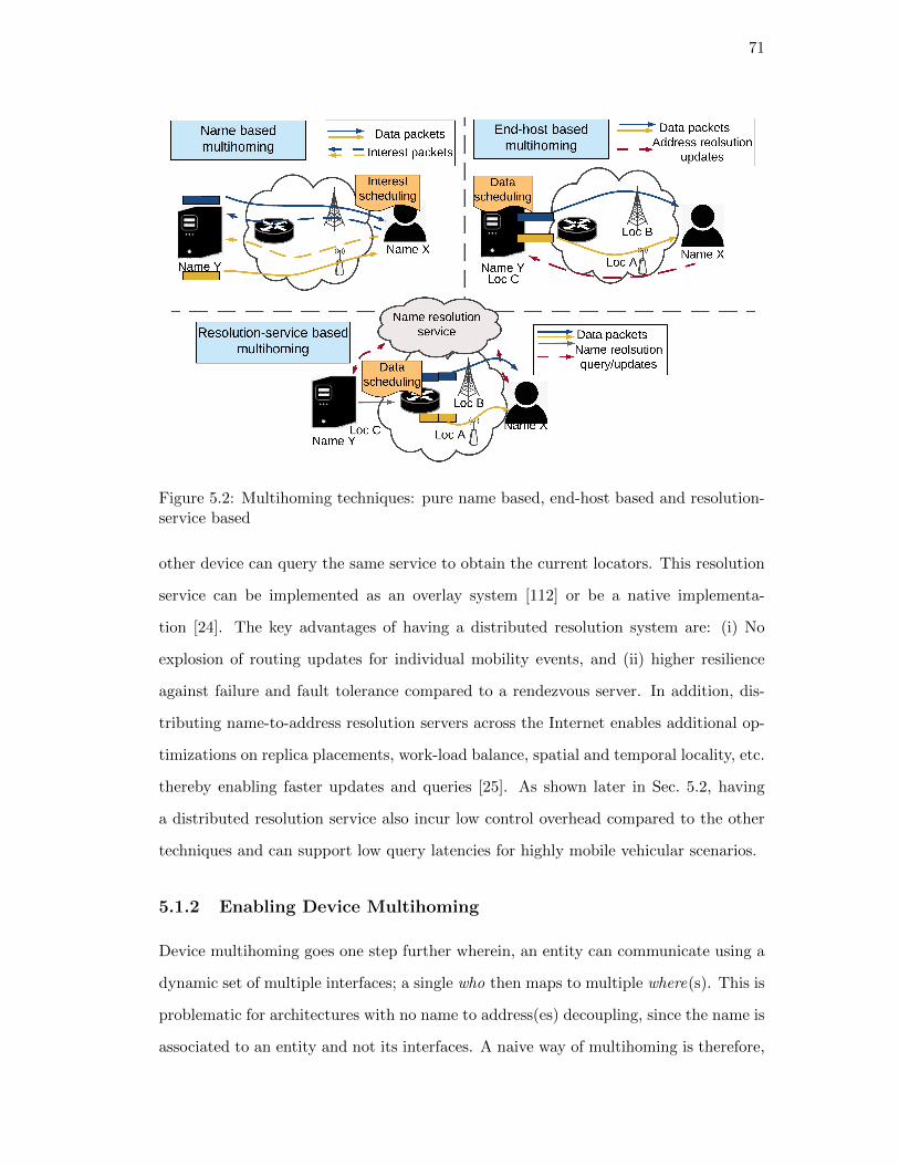
71
Figure 5.2: Multihoming techniques: pure name based, end-host based and resolution-service based
other device can query the same service to obtain the current locators. This resolution
service can be implemented as an overlay system [112] or be a native implementa-
tion [24]. The key advantages of having a distributed resolution system are: (i) No
explosion of routing updates for individual mobility events, and (ii) higher resilience
against failure and fault tolerance compared to a rendezvous server. In addition, dis-
tributing name-to-address resolution servers across the Internet enables additional op-
timizations on replica placements, work-load balance, spatial and temporal locality, etc.
thereby enabling faster updates and queries [25]. As shown later in Sec. 5.2, having
a distributed resolution service also incur low control overhead compared to the other
techniques and can support low query latencies for highly mobile vehicular scenarios.
5.1.2 Enabling Device Multihoming
Device multihoming goes one step further wherein, an entity can communicate using a
dynamic set of multiple interfaces; a single who then maps to multiple where(s). This is
problematic for architectures with no name to address(es) decoupling, since the name is
associated to an entity and not its interfaces. A naive way of multihoming is therefore,

72
to send routing updates across all the interfaces, such that data packets can be received
on all of them. For CCN, which works on polling, this means sending out redundant
interests across all available interfaces and receiving the same data across all, causing a
wastage of network resources. The authors in [113] propose having a scheduler on the
end-host that can split interest packets on different interfaces thereby receiving different
data packets on the reverse path (Fig. 5.2). While this helps in improving overall
throughput at the client, it still suffers from a control overhead explosion on mobility
scenarios, in which case interest messages need to be resent every time one or more
of these interfaces change point of attachment. Having a scheduler on the end-device
also requires additional sophisticated machinery to implicitly measure or estimate the
access link quality and congestion characteristics in order to efficiently schedule interest
packets, which may not be viable for a resource and power-constrained end-device.
End-host based multihoming techniques follow similar principles as mobility, namely,
end-points communicating directly to exchange name to multiple locator’s information.
This means a scheduler should run at the other end-point to split the flow for each of
the addresses of the interfaces. Similar to the mobility scenario, a rendezvous server is
necessary for initiating the flow when both the end-point’s locators are changing [110].
Likewise, NRS based architectures update entity names to multiple addresses in the
resolution service and query as and when these locators are updated. Moreover, through
the service intent specification, the in-network components can be aware of the end-
user’s desired multihoming mode. Data schedulers can then be located within the
network at a suitable bifurcation point, which enables fine-grained control based on
accurate link and bandwidth characteristics, leading to significant improvements in
overall end-host throughput [31,32].
5.1.3 Support for Large Multicast Groups
Pure name based architectures inherently support multicast by, (i) having receivers
flood interest packets, and, (ii) routers serving multiple pending interests simultane-
ously across the reverse path of interest. However, flooding of interest for every mul-
ticast request across the internet does not scale. Only the introduction of rendezvous

73
Figure 5.3: NRS multicast tree overloading compared to name based polling approach.
points [114], similar in spirit to IP multicast, and new packet formats can reduce such
impact.
While name based architectures can still fall back on IP multicast techniques in
order to support multicast [115, 116] and exploit names only to enhance the existing
protocols (e.g. HIP security handshake across peers [115]), a more efficient technique
is to instead the use of name abstractions (i.e. named-object) to overload multicast
trees into the NRS thereby reducing the overall control overhead [3]. In this case,
each branching router along the tree is assigned a unique name specific to that tree,
which recursively map to their children or downstream branching routers (Fig. 5.3).
This name based tree is stored in the name resolution service for ease of management,
allowing branching routers to query and forward packets along the tree. Since name-
address decoupling already handles mobility efficiently, this scheme can also handle
receiver mobility, ensuing no packet is lost during multicast receiver mobility.
5.2 Evaluation
In order to characterize the effectiveness of the named-object abstraction compared to
LISP, HIP and CCN, packet-level simulations using both NS-3 and a custom simulator
have been performed. These focus on both control overhead and data throughput
for the three use cases described earlier, namely: device mobility, multihoming and
multicasting.
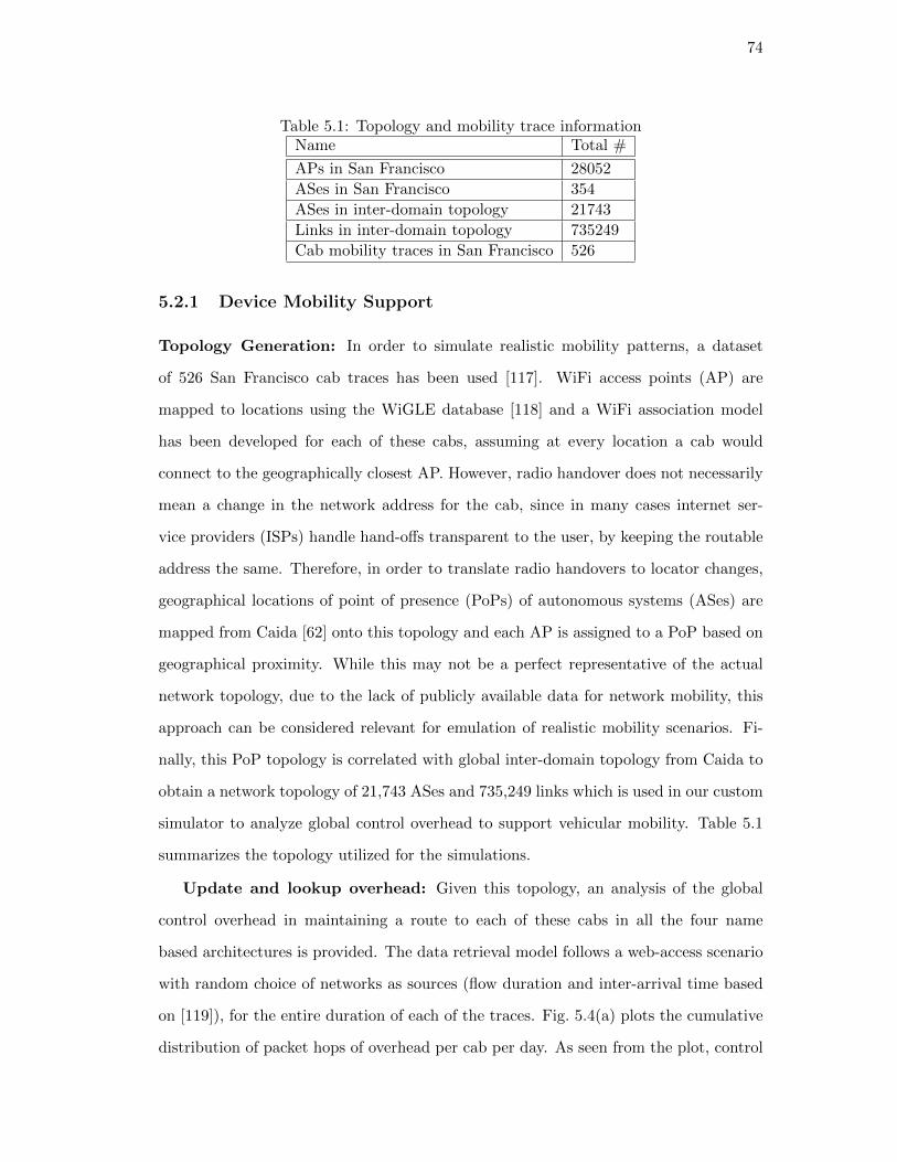
74
Table 5.1: Topology and mobility trace informationName Total #
APs in San Francisco 28052
ASes in San Francisco 354
ASes in inter-domain topology 21743
Links in inter-domain topology 735249
Cab mobility traces in San Francisco 526
5.2.1 Device Mobility Support
Topology Generation: In order to simulate realistic mobility patterns, a dataset
of 526 San Francisco cab traces has been used [117]. WiFi access points (AP) are
mapped to locations using the WiGLE database [118] and a WiFi association model
has been developed for each of these cabs, assuming at every location a cab would
connect to the geographically closest AP. However, radio handover does not necessarily
mean a change in the network address for the cab, since in many cases internet ser-
vice providers (ISPs) handle hand-offs transparent to the user, by keeping the routable
address the same. Therefore, in order to translate radio handovers to locator changes,
geographical locations of point of presence (PoPs) of autonomous systems (ASes) are
mapped from Caida [62] onto this topology and each AP is assigned to a PoP based on
geographical proximity. While this may not be a perfect representative of the actual
network topology, due to the lack of publicly available data for network mobility, this
approach can be considered relevant for emulation of realistic mobility scenarios. Fi-
nally, this PoP topology is correlated with global inter-domain topology from Caida to
obtain a network topology of 21,743 ASes and 735,249 links which is used in our custom
simulator to analyze global control overhead to support vehicular mobility. Table 5.1
summarizes the topology utilized for the simulations.
Update and lookup overhead: Given this topology, an analysis of the global
control overhead in maintaining a route to each of these cabs in all the four name
based architectures is provided. The data retrieval model follows a web-access scenario
with random choice of networks as sources (flow duration and inter-arrival time based
on [119]), for the entire duration of each of the traces. Fig. 5.4(a) plots the cumulative
distribution of packet hops of overhead per cab per day. As seen from the plot, control

75
10 100 1,0000
0.075
0.2
0.40.50.6
0.8
1
2.4x
Pkt hops control overhead per cab per day
CD
Fac
ross
534
cabs
MF(GNRSrep. 3)HIPLISP(Alt o/l.20%)CCN(flood:10%)
(a)
10 100 1,0000
0.2
0.4
0.6
0.8
1
Pkt hops control overhead per cab per day
MF(GNRSrep. 1)HIPLISP(Alt o/l100%)
(b)
Figure 5.4: Control overhead comparison for (a) maintaining mobility and, (b) using asingle replica NRS
overheads for MF, HIP and LISP are comparable. In comparison median overhead of
CCN is about 2.4 times higher than the others. This is because in CCN, every time a
device moves, it needs to propagate a routing update to enable other networks to route
packets to itself. However due to the hierarchical nature of CCN names, not every
mobility event causes an update. For example, if a device named /att/rutgers/alice/
moves from the domain rutgers and connects directly to att, the latter does not need
to propagate an update. For this simulation, it is assumed that every network forwards
only 10% of the total routing updates it receives to its neighbors. As seen from the
plot less than 8% of the events result in very low routing updates due to hierarchical
naming, but on an average, pure name based routing has a much higher overhead.
Although MF, HIP and LISP have comparable overheads, it is worth mentioning
that HIP performs an end-to-end handshaking, whereas MF and LISP both update
their respective resolution services, for every mobility event. The resolution service for
MF (GNRS) is in-network with 3 replicas stored for each name. LISP, on the other
hand, uses an overlay based scheme and has an inherent overhead of maintaining overlay
topology using BGP. Fig. 5.4(a) does not take into account BGP and considers 20% of
the networks randomly chosen to have an overlay server.
Increasing the number of ALT servers (with corresponding increase in topology
maintenance overhead) will further improve LISP control overhead with the minimum

76
1
50 52 54 56 58 60 62 64 66 68 70 72 74
0
1
2
3
4
Time(seconds)
Thr
ough
puta
tthe
mob
ilede
vice
(Mbp
s)
MF/LISPHIP
Disconnection
Name resolution lookupat source & edge router
E2E 3-way handshake
Storage-awarerouting (MF)
Figure 5.5: Data delivery to a moving vehicle while it disassociates and re-associateswith WiFi APs
being for all networks participating in ALT (similar to the GNRS implementation), as
highlighted in Fig. 5.4(b). On the other hand, reducing the number of GNRS replicas to
1, will reduce the control overhead for MF, but also corresponding reduce its resiliency
to failures. As shown in Fig. 5.4(b), MF overhead would lie somewhere in between LISP
and HIP in such cases.
Handover and data throughput: Given that MF, LISP and HIP have much
less overhead in managing mobility, a comparison of the three is provided for data
throughput during mobility and temporary disconnection with handovers, using packet
level simulation in NS-3. In this experiment, a single device moves away from its
associated AP along a straight line, and following a period of disconnection connects
to another, while downloading a large file form a back-end server. Core link delays are
set to 10 ms whereas edge links have 1 ms delay, as shown in the top-left of Fig. 5.5.
This topology although simple, in essence simulates a similar cab mobility trace but
with accurate control of AP placements and mobility. MF/LISP evaluation considers
a single replica resolution server which all the routers can update and lookup. MF
routers are also storage capable [28], so that every router can temporarily store data
on disconnection and re-route once an up-to-date mapping is available.

77
2 3 4 5 6 8 10
101
102
103
104
Multihomed interfaces
Ave
rage
pack
etho
psof
cont
rolo
verh
ead
MF (1 update for all interfaces, GNRS rep. 3) CCN dest interestMF (1 update/interface, GNRS rep. 3) CCN source register
Figure 5.6: Control overhead for multihoming support with increasing number of inter-faces in a 1000 network random graph
As highlighted in Fig. 5.5, following disconnection at about 61 seconds, data through-
put goes to zero. For MF/LISP both the AP it was last connected to and the source
periodically re-queries the server for new address mapping of the device. As soon as
the server is updated at about 70 seconds, data delivery resumes for the device. For
HIP however, end-to-end 3-way handshaking takes longer to complete and data delivery
resumes around 71 seconds. Finally, Fig. 5.5 also shows the benefit of storage-aware
routing in case of MF, wherein the previously associated AP temporarily stores in-flight
data and binds them to the new address following resolution server update and re-routes
it along the edge.
5.2.2 Multihoming support
Next, control overhead is evaluated for the maintenance of multiple interfaces at a
client with data delivery across all interfaces. The graph employed is an Erdos-Renyi
1000 node random graph with a randomly chosen source network and variable number
of randomly chosen interfaces for the destination. Comparison is done only between
resolution-service based approach of MF with pure name based approach of CCN, since
comparative studies of in-network multihoming against end-to-end approaches such as
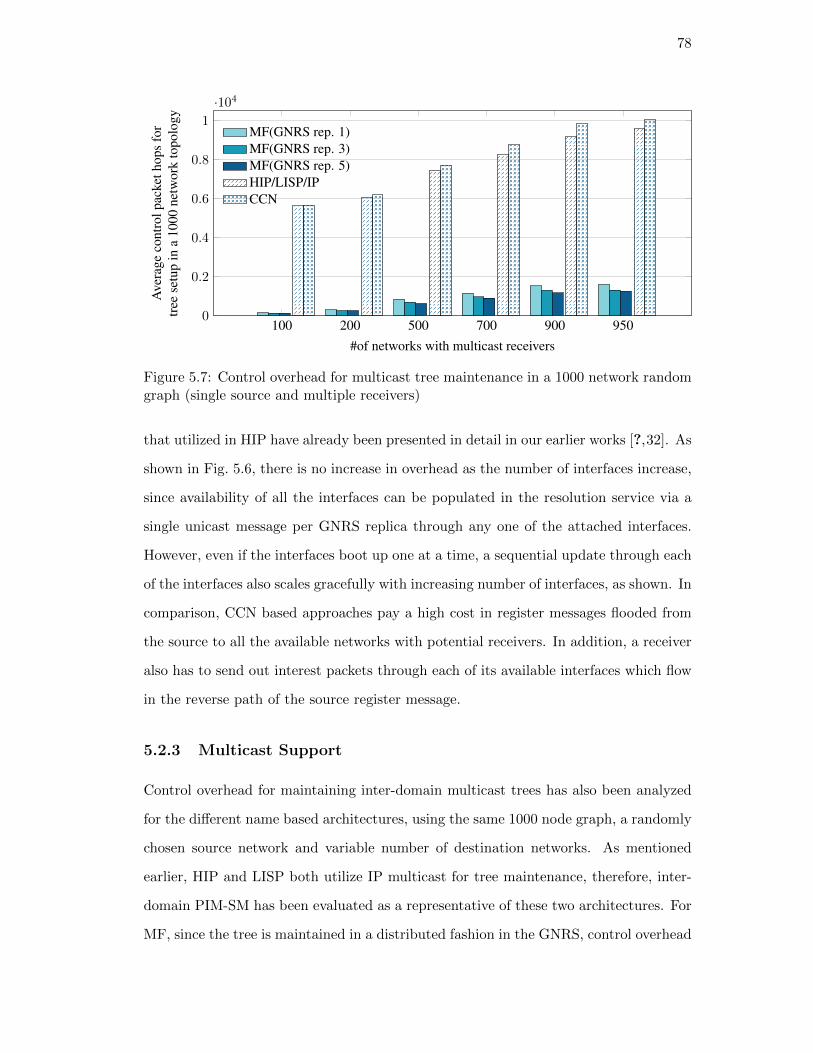
78
100 200 500 700 900 9500
0.2
0.4
0.6
0.8
1
·104
#of networks with multicast receivers
Ave
rage
cont
rolp
acke
thop
sfo
rtr
eese
tup
ina
1000
netw
ork
topo
logy
MF(GNRS rep. 1)MF(GNRS rep. 3)MF(GNRS rep. 5)HIP/LISP/IPCCN
Figure 5.7: Control overhead for multicast tree maintenance in a 1000 network randomgraph (single source and multiple receivers)
that utilized in HIP have already been presented in detail in our earlier works [?,32]. As
shown in Fig. 5.6, there is no increase in overhead as the number of interfaces increase,
since availability of all the interfaces can be populated in the resolution service via a
single unicast message per GNRS replica through any one of the attached interfaces.
However, even if the interfaces boot up one at a time, a sequential update through each
of the interfaces also scales gracefully with increasing number of interfaces, as shown. In
comparison, CCN based approaches pay a high cost in register messages flooded from
the source to all the available networks with potential receivers. In addition, a receiver
also has to send out interest packets through each of its available interfaces which flow
in the reverse path of the source register message.
5.2.3 Multicast Support
Control overhead for maintaining inter-domain multicast trees has also been analyzed
for the different name based architectures, using the same 1000 node graph, a randomly
chosen source network and variable number of destination networks. As mentioned
earlier, HIP and LISP both utilize IP multicast for tree maintenance, therefore, inter-
domain PIM-SM has been evaluated as a representative of these two architectures. For
MF, since the tree is maintained in a distributed fashion in the GNRS, control overhead

79
is affected by the number of replicas maintained. Interestingly, increasing the number
of replicas leads to a reduction in overall control traffic, as shown in Fig. 5.7. This is
due to two main reasons: (i) Updates are less frequent than lookup queries, and, (ii)
during lookup using anycast, there is at least one server which is close to the querying
router. In comparison, both IP multicast and CCN have a much higher overhead even
for a small sized graph, because both of them rely on some form of flooding to build the
tree. In CCN, multicast receivers flood interests, whereas in IP multicast, the source
floods a source-active message throughout the network [102]. In fact, even with a single
replica and 90% of the network having multicast receivers MF improves average control
overhead by a factor of 6.4 compared to the alternative schemes and the gain goes up
to a factor of 37 when only 10% of the network have multicast receivers.
5.3 Summary
This chapter highlighted how compared to other name based approaches, Named-
Objects are capable of reducing control overhead while still improving performance
in different common scenarios like mobility, multi-group and multi-homed delivery. As
these base services are the underlying foundation of a multitude of different network
applications, our future research will explore ways to demonstrate how Named-Objects
could be employed in a wider and more advanced set of service scenarios for future
mobile Internet architectures.

80
Chapter 6
A Distributed Mobile Core
6.1 Introduction
As Internet-connected mobile devices will soon outnumber fixed PCs, a convergence
of business models and technical standards associated with cellular networks and the
Internet may be expected over the next decade. This process has already started, with
cellular standards embracing the concept of “flat” IP-based networks without central-
ized gateways. In 4G/LTE, the cellular access network architecture has been signifi-
cantly flattened with only a single specialized MME (mobility management entity) in
the control path and PGW and SGW (packet and service gateways) in the data path,
and with commodity routers everywhere else in the network. We predict that this trend
will continue with the evolution of 5G new radio and the 5G core [9–11, 120]. In our
view, the next logical step in this direction is a completely flat mobile network architec-
ture with native support for basic services such as authentication, dynamic association
and handover, inter-network roaming, and disconnection tolerance. In the integrated
“mobile Internet” architecture, it will be possible to “plug in” multiple wireless access
technologies such as 4G, 5G or WiFi in a completely flat control and data plane without
requiring gateways. Such a uniform protocol solution across wired and wireless network
technologies will eventually lead to convergence of cellular and Internet standards, in
view of the fact that both industries are serving the same mobile end-users.
The 3GPP standardization efforts on 5G propose to revamp the cellular core network
architecture to cater towards high bandwidth and low latency requirements for existing
and future 5G applications. The latest release (release 15) [121] focuses on two aspects
of the architecture. First, the access medium has a standard for a new radio (5G-NR)
with improved performance benefits. Second, the core network has been redesigned to

81
Figure 6.1: The 5G network architecture: functional services and physical resources
have a service-oriented view in order to better support network function virtualization
and slicing. Fig. 6.1 shows a breakdown of the major functional modules in the 5G
core network. Modularizing based on service functions is a useful first step towards
decomposing the core network into distinct components that operators can pick-and-
choose to create different types of core networks that can then be implemented as a
slice over the physical fabric.
The physical fabric of the core network is currently designed to be hierarchical in
nature with vendor specific gateways. All data flows through tunnels between base
stations (enBs in 4G or more generally, BSs) and the session and packet gateways
(SGWs and PGWs), resulting in both scalability and latency problems. Further, new
requirements such as heterogeneous access networks or support for IoT introduce design
challenges that cannot be addressed with incremental performance improvements to the
current gateway-based design thus motivating a more comprehensive re-examination of
the architecture as a whole. Take for example, a low latency computation service that
processes images from hundreds of street-level cameras to capture an amber alert license
plate. One way it can be realized through the existing mobile core network architecture
is to provide computation at the access network to reduce transmission delay across
the network. But this would require bypassing the network gateways and associated

82
UE eNodeB MME HSS SGW PGW
RRC Connection Request
Authentication Request
RRC Connection Setup
Authentication Response
RRC Connection Setup Complete
NAS Attach Request
Authentication Request
Authentication Response
NAS Security Mode Command
NAS Security Mode Complete
Update Location Request
Update Location Response
Create Session Request
Create Session Request
Create Session Response
Create Session Response
Attach Accept
UE Capability Request
UE Capability Response
RRC Connection Reconfig
RRC Reconfig Complete
Attach Complete
Initial Context Setup Response
Authentication & Security
Mobility Management
Session Management
Evolved Packet Core (EPC)
Figure 6.2: Control messaging to establish uplink data connectivity for a user equipment(UE) using 4G
tunneling protocols altogether through overlays or proxies implemented specifically for
this use case. This motivates a distributed flat architecture that can provide better
flexibility in meeting the needs of services requiring core network infrastructure as
well as those needing edge cloud computation close to the access network, through
its distributed routing and forwarding. The key question to ask is therefore can we
achieve the control benefits of a hierarchical architecture with the benefits of flat routing
and forwarding? The goal of this work is to present a distributed flat core network
design that uses the named-object concept of MobilityFirst in order to achieve better
routing efficiency, latency and scale while enabling future services along with the basic
functionalities of a mobile core network.
6.1.1 Current Cellular Core Network Design
The cellular network architecture was designed primarily for long-lived data sessions.
Following the terminologies of the evolved packet core (EPC) in 4G, this consists of a
centralized mobility management entity (MME) with a home subscription server (HSS),

83
and packet and service gateways (PGW and SGW). Every time an UE requires data
connectivity, a list of handshakes and messaging between different components of the
EPC and the RAN needs to take place before any data packet can be transmitted.
Fig. 6.2 highlights the control messages for uplink data network connectivity for an
UE. The key functionalities include authenticating the UE, updating its location in
terms of the eNB it is currently connected to, and setting up dedicated bearers from
the eNB to its serving gateway. Not only is this latency intensive, this procedure repeats
every time a UE switches from idle to active state. As seen from Fig. 6.2, the total
number of control messages can be as high as 17 for every idle to active transition.
One of the main shortcomings of this hierarchical architecture design is that the
data-plane path is setup and managed between the BS and the gateways using the
GTP tunneling protocol [122]. The gateways perform this task, by setting up dedicated
tunnels for each UE, identified by tunnel identifiers, generated during the protocol
exchanges shown in Fig. 6.2. Every data packet then needs to be encapsulated and
de-encapsulated at the tunnel endpoints (BS and the PGW), which adds to the data
overhead and complexity of the architecture design. These tunnels are torn down and re-
established with every mobility event, creating even more overhead. To add to that, as
the authors in [123] show, most US based cellular providers have only 4-6 such gateways
to handle traffic from millions of subscribers. This still works if the number of devices
connecting through the core is reasonable, they do not have stringent latency and
control packet processing limitations, and, maintain long-lived connectivity patterns
(active tunnels), similar to smartphones. However, once we start to relax some these
assumptions for devices such as sensors in a smart-vehicle, or industrial control and
interpolate the predicted growth of heterogeneous devices connecting through 5G, the
gateways become source of serious bottlenecks, as shown in our evaluations in Sec. 6.3.
6.1.2 Motivation for a flat core network
We summarize below the key service requirements that motivate the switch from a
hierarchical network to a flat mobile core.
Ultra high bit rates: Access network throughput per mobile user is expected to

84
increase dramatically with new access technologies such as 5G-NR, now being standard-
ized by 3GPP. However, studies have shown that a typical US based network provider
has only a limited number of gateways (4-6) [123] for its national scale network through
which all endpoint traffic enters/exits the network. The end-user throughput in the
end will be limited by the capacity of these gateways in such a hierarchically designed
network. With Gbps speeds on the radio access links, the total traffic carried by the
network with 1000s of active users will be of the order of Tbps. A single gateway (or
even multiple gateways with NFV) cannot easily handle such a large amount of traffic,
motivating a flat architecture in which traffic can flow through any mobile core network
router in a distributed manner, following the natural shortest path instead of being
tunneled through a single gateway.
Low latency: Achieving orders of magnitude lower latency has been a major goal
for 5G [121]. Latency of packet delivery is due to a number of factors including delays in
both the control and the data plane. One of the dominant delays in mobile networks is
the control plane latency associated with setting up a path for forwarding that packet.
Typically, cellular networks involve a bootstrapping phase where an attaching device
needs to authenticate and setup a session with the network. Given the hierarchical
nature of the network and the legacy components, this step may involve more than
20 messages to be exchanged with the mobility management entity (MME) and the
gateways and can take as much as 75 milliseconds on an average before a session can be
established [124]. As shown later, these messages are used primarily for three purposes:
authentication, mobility management and session management. In the conventional
gateway architecture, initial gateway signaling latencies can be significant components
of the overall delay. In a distributed flat network, we envision a shift from a per flow
signaling to a more distributed packet switching approach, wherein forwarding decisions
are made on a packet-to-packet basis instead of maintaining a long-lived end-to-end
session to a packet gateway. This is especially beneficial for devices that do not send a
large of amount of data at a time, such as IoTs, as described next.
Support for IoT: According to requirement studies by 3GPP, 5G should aim to
support about 52K IoT devices per cell-sector [125]. It is assumed that most of these

85
devices will be power-constrained while sending sporadic bursts of short packets. Con-
sequently, their requirements are quite different from typical cellular endpoints. High
bandwidth is not a strict requirement, but low overhead control protocols are required
in order to improve network efficiency (loosely defined as the ratio of data vs. control
bytes). Narrowband IoT (NB-IoT) is the current solution proposed by the community
that assigns a separate channel solely for the use of IoTs. However, if NB-IoT is used
in conjunction with the existing core network, this will result in high control overhead
compared to the low data traffic rate that IoTs typically need. One solution proposed
for NB-IoT is to go through all the control protocols for authentication, mobility and
session management during bootstrapping but then cache this state at the BS. Once
this is done, the session does not need to be reestablished every time a device wakes
up to send a few bytes of data. This approach is based on the assumption that these
devices are static and will not require handover capabilities. However both of these
assumptions seem to focus on only a subset of the full range of IoT devices which
may span anywhere from static power-constrained motes on an agricultural farm to
highly mobile automotive tire pressure sensors. Many of these will be unable to use
NB-IoT unless significant improvements in the protocols are made to improve latency
and support mobility.
Heterogeneity in access networks: 3GPP release 15 envisions multiple access
networks that can be plugged into the same core network. The core network should
be radio technology agnostic and support a mix of 4G, 5G and WiFi radio access
technologies. For this purpose, all the components of the core have been modularized
such that if required a subset of these components can be stitched together to form a
network by bypassing the rest of the modules. This is relevant to the design proposed
here, as modularization is consistent with a distributed flat core that can be stitched
to multiple heterogeneous access networks. In order to utilize multiple of these access
networks simultaneously and more efficiently, a distributed core will provide better path
availability and reduce the chances of traffic bottleneck.
We note that a unified mobile Internet architecture is useful to both cellular network
operators seeking to improve performance, as well as to more general Internet service

86
providers (ISPs) aiming to introduce mobility services across heterogeneous access net-
works. For example, an ISP that currently offers standard Internet access service could
expand the offering to include seamless mobility across multiple wireless networks such
as WiFi hot-spots using standard network elements (router, BSs, access point) without
the need for a specialized control framework. This type of heterogeneous wireless ac-
cess service is sometimes referred to as “open wireless networks” [126] in which loosely
coupled access networks use a common protocol to support basic mobility needs such
as authentication, handover and inter-network roaming. Such access networks may be
expected to become a viable alternative to managed cellular services if they are able
to offer a level of access and mobility that could be adequate for some portion of end-
users and applications. Cellular providers incorporating WiFi hot-spots and 5G small
cells to supplement their existing macro-cellular deployments could also use the same
flat future IP protocol to provide mobility services across these heterogeneous networks
without the need of any specialized network equipment.
The rest of the chapter is organized as follows:
• Enumerate the scalability bottlenecks in the evolved packet core (EPC) of cellular
networks.
• Propose a distributed core network architecture for handling increased scale at sig-
nificantly lower overhead, while preserving identity and security requirements of cellular
networks and enabling flexible creation of new mobility and IoT services.
• Provide results from a large scale simulation study on a US based cellular network
operator comparing the 4G EPC architecture with the flat network architecture in
terms of scalability and control overhead.
• Present prototyping and implementation results on a low latency IoT usecase, com-
paring the proposed architecture with a 3GPP compliant commercial core network
implementation.

87
Figure 6.3: MF-Core Architecture with breakdown of key functionalities handled dis-tributedly at the eNBs
6.2 A Flat Cellular Core Design
Based on the above requirements, the flat mobile core has the following key features:
(i) Distributed control: There are no gateways in the architecture and no end-to-end
session management protocols; (ii) Routing functions distributed across all network
components: Access networks as well as core network components all perform routing
and mobility management functionality; (iii) Traffic can flow into and out of the network
freely to and from multiple ingress and egress points.
6.2.1 Architecture Overview
The network architecture is outlined and compared with the existing 3GPP architec-
ture in Fig. 6.3. The distributed core network removes the service and packet gateways
(SGW and PGW) and the MME but instead utilizes MobilityFirst unique identifiers for

88
(a) (b)
Figure 6.4: Comparison of end-to-end protocol stack for 6.4(a) LTE and 6.4(b) MF
UEs along with a distributed mapping service to support mobility. In the MobilityFirst
architecture, this service is called a global name resolution service (GNRS) and is imple-
mented as a distributed hash table in which all routers of the network participate. The
authentication entity, which is tasked with maintaining UE subscription, policy and
charging information of the network, still remains as part of the core. The BSs com-
municate with it directly to authenticate an UE and obtain relevant policies pertaining
to that UE during the bootstrapping phase. With no session management functions,
the bootstrapping phase now only has authentication and a distributed mobility man-
agement. The network being completely flat allows a plug-and-play capability, where
multiple radio access technologies (such as 4G, 5G or WiFi) can be plugged in to or-
ganically grow the network provided they participate in the control plane that supports
the distributed mapping and authentication functions. Fig. 6.4 further shows how the
network stack is simplified once the gateways are bypassed. Next, we describe each of
the core functionalities enabled at each of the routable entities in the network.
Authentication and Device Onboarding: The device onboarding steps are
shown in Fig. 6.5. Whereas, the RRC connection setup, authentication and UE attach-
ment to the network remains unchanged, the BSs now need to perform the policy and
QoS enforcement, typically performed at the P/S gateways when data is exiting or en-
tering the core network through GTP tunnels. Distributing the charging functionality
close to the edge reduces the control bottleneck at the limited number of gateways as

89
UE eNodeB HSS Mapping System
RRC Connection Request
RRC Connection Setup
RRC Connection Setup Complete
Attach Request
Attach Response
Security Mode Command
Security Mode Complete
UE Capability Request
UE Capability Response
RRC Connection Reconfiguration
RRC Connection Reconfiguration Complete
Update Mappings
Update Ack
Authentication & Security
Mobility Management
Figure 6.5: Control messaging to establish uplink data connectivity for an UE usingMf-Core
well as allows for interesting charging policies to be implemented, such as charging local
traffic differently than traffic traversing multiple hops out of the service provider net-
work. In addition to that, the BSs in this distributed identity based architecture need to
update device ID to routable locator (BS address) mapping in the mapping database, as
shown. With no session management functions, the bootstrapping phase now only has
authentication and a distributed mobility management. The network being completely
flat allows a plug-and-play capability, where multiple radio access technologies (such as
4G, 5G or WiFi) can be plugged in to organically grow the network provided they par-
ticipate in the control plane that supports the distributed mapping and authentication
functions.
Mobility management: The distributed mobility service is based on the global
name resolution service deployed in MobilityFirst [24]. In this service all routers in
the network participate in a distributed hash table implementation, wherein all the
mapping of endpoint names to their routable addresses (address of the BSs an endpoint
is connected to) is stored across all the routers in the network. The mapping service is
therefore physically distributed, however, as in any hash table implementation, given
an endpoint name, it can be hashed to obtain the unique address of the router that

90
Figure 6.6: Control and data plane for the distributed core with named object identifiersand distributed mapping service
needs to be queried in order to find the up-to-date name-address mapping and hence
the current location of that endpoint. The service also has resiliency mechanisms such
as storing the mapping information of an end-point at multiple locations using multiple
hash functions, in case any of the routers go down. The control overhead of maintaining
such a distributed mapping service is light as these routers do not need to run additional
synchronization protocols, provided they all have adequate storage capabilities and the
bandwidth for query/response of their local databases. Prior works on such distributed
services have proven them to be scalable to Internet size networks. For the global
Internet detailed evaluations have shown query/response latencies to be as low as 10
milliseconds [127].

91
Packet forwarding: Given the underlying routing and the mapping services, a UE
joining the network first establishes radio level connection with a nearby BS, followed
by authentication at the BS via similar protocols as in 5G, as shown in Fig. 6.6. Once
this is completed, policy and charging information are communicated directly to the
authenticating BS and the UE name-to-address mapping is updated in the mapping
service. In the data plane, now data can flow freely following a packet-switched network
paradigm. A MobilityFirst specific data plane scenario is highlighted in Fig. 6.6, where a
data packet carries both the endpoint identifier and the current location of the endpoint.
A source UE sends data to a destination identified by a name (Dst ID). The first hop
router at the BS looks up the database to find the Dst ID to address mapping which is
then appended to the packet. Consecutive routers simply forward packets by looking
up their forwarding tables for that particular address. Packets therefore enter and exit
the core network along the best intra-domain routing path, which may also reflect UE
specific policies.
Note that although this architecture design is based on MobilityFirst, the cellu-
lar core network design proposed is agnostic to any naming, name-address separation
protocols and mapping system designs and therefore, can work with any of the alter-
native name-based architectures that use IP semantics, such as HIP [7], LISP [8], and,
ILA [128]. The packet structure shown in Fig. 6.6 carries both the identifier and the
routable address, following MobilityFirst packet syntax. For alternative identity-based
architectures this packet format and the mapping-function at the eNBs would be dif-
ferent. For example, LISP [8] encapsulates the original packet with a new IP header
carrying the destination IP address, while ILA rewrites the destination identifier with
the destination address [128]. However, the core network architecture, the distributed
mapping system and the protocol syntax can adapt well to such alternative designs.
Next, we walk through a few data-plane services to highlight the benefits of using the
distributed core network.

92
6.2.2 Dataplane Services
In this section, we walk through three data-plane services, namely, (i) a voice-over-
IP call between two smartphones both subscribed to the same network carrier; (ii)
service chaining and flexible policy enforcement at a cellular service provider; and,
(iii) a mobile edge-computing usecase, where an mobile endpoint running an AR/VR
application requires computation service from the network.
VOIP between local mobile users: We start with the assumption that both the
smartphones are in RRC connected state and have already authenticated and attached
to the network following the protocol diagram in Fig. 6.5. As shown in Fig. 6.7, UE
1 is initiating a data flow to UE2. Following the concept of a identity-locator split
architecture, the first packet at the BS will incur a mapping database lookup to find
the routable locator for UE2 (which in this case is the address of eNB2). Our design
assumes that this mapping is cached at the BS for the lifetime of this VOIP flow
and hence, consequent packets would not require further lookups. Based on the core
network topology and the routing protocols within the core network, the packets will be
forwarded across the shortest path through the network to eNB2. If we contrast this to
what would happen for the same application in the EPC, we will observe that all packets
from eNB1 will be encapsulated and tunneled to a PGW deep into the network, from
where they need to be de-encapsulated, followed by encapsulated a second time and
sent via a second tunnel to eNB2. The actual route followed by the packet may be quite
non-optimal, both from the user and the network perspective, especially considering the
limited number of PGWs per carrier [123].
Service chaining: Next, we describe a second usecase, where a cellular service
provider wants to implement flexible policies, QoS and network functions within the
network. In this case, service functions are instantiated by assigning identities to the
service and storing an up-to-date mapping between the service identifier and its loca-
tion in the mapping system. As shown in Fig. 6.8, network functions such as filtering,
and deep packet inspection (DPI) can be chained together for a particular flow, sim-
ply by inserting the correct order of mapping of locators in the mapping system. For

93
Figure 6.7: Enabling VOIP call between two subscribers of the same network throughthe distributed core
example, based on the SLA agreements and QoS policies, data packets from UE 1 are
first directed to a filtering service, from where a second lookup in the mapping system
is made to direct it to a DPI service, after which it is forwarded to an egress router.
On the other hand, packets from UE2, which could have a different agreement for lower
latency, is forwarded out into the backbone through the closest egress router. Avoid-
ing P/S gateways allows the network to implement many such flexible policies without
having to instantiate and maintain multiple GTP tunnels between each network func-
tion. In addition, decoupling the service names from their routable addresses provides
flexible traffic engineering capabilities to the network, as any function can now be easily
moved or assigned to multiple locations in the network, simply by inserting the correct
mappings in the mapping system.
Mobile edge computing: Mobile edge computing (MEC) has been introduced in
the 5G specifications in order to support applications requiring compute functionalities
with low round trip latencies, such as autonomous driving, AR/VR and industrial
control. Edge computing requires much lower latencies than what a typical cloud can
offer and therefore needs compute resources pushed as close to the user as possible,

94
Figure 6.8: Instantiating flexible services and QoS policies in the distributed core net-work
that is, right at the radio access network. Since computing is treated as an application
function and traditionally located in the data network (after the flow exits the core
network), an incremental solution proposed in 5G is to have gateways at the edge as well
as at the core, as shown in Fig. 6.9 [129]. But this requires additional protocols in order
for edge and core gateways to communicate with each other and the MME. As explained
earlier, such protocol overhead will adversely affect the low latency requirements of
these applications. In addition, session handover protocols need to be designed and
implemented when the user moves from one packet data network to another which may
result in breaking of session with one gateway and making a new session with the next.
Named object architectures have the benefit of assigning names not just to users but also
to identify specific services. For example, in MobilityFirst, an edge-computing service
for an AR application is assigned a unique identifier. The service itself is distributed
across various edge locations in the core and an up-to-date mapping of this service to all
its locations is maintained in the name resolution service. Packets requiring this service

95
Figure 6.9: Mobile edge computing in 5G (left) and in the distributed flat core (right)
are identified by the service name and anycast to the nearest service instance. This
simplifies the control overhead of the application as (i) it does not require maintaining
(making/breaking) of sessions with one or multiple edge locations; (ii) the network
provider can spin up new instances of the service based on traffic demands without
having to set up gateways and protocols for the new edge network; (iii) the service
itself is agnostic to user-mobility as the distributed routing and anycasting will forward
UE requests to the closest edge server.
6.3 Evaluation
In order to evaluate the proposed distributed core, we performed detailed simulation
followed by prototyping and experimentation on the ORBIT testbed. The set of results
from the simulations have been published in our paper [130].
6.3.1 Control overhead simulation
Realistic System Model: We focus on a single US based cellular carrier, referred
henceforth as C1, which reported 138.83 million wireless subscribers in 2017 [131]. We
also consider future predictions of wireless subscriber growth [4] and IoTs using cellu-
lar. [132] predicts there will be as many as 52,547 IoTs per cell site in the near future.

96
Table 6.1: Simulation ParametersParameter Value
UEs(smartphones) 138.83 106
UEs(IoTs) 33 106
eNB cell sites 637494
PGWs 6
SGWs {6,12,18,24}MMEs {6,12,24,36,48}Routers 82756
Links 441136
We estimate that would result in about 33 billion IoTs for C1. We assume that not
all these devices would have resources to communicate directly with a basestation and
instead assume a more modest growth of 33 million in our simulation. We parse the
opencellid dataset to obtain crowd-sourced data of about 650K cell sector locations
for C1 [133]. Note that the actual number of eNBs will depend on the number of cell
sectors of each of C1’s eNBs, the information of which was unfortunately not available.
We assume that C1 has at-most 6 PGWs (based on [123]), and then parametricize
the number of SGWs and MMEs as multiples of PGW. For the data-plane topology,
we parse reported router-level topology of C1 from Caida [62], that results in a dis-
tributed topology of about 82K nodes and 441K links. The simulation parameters are
summarized in Table 6.1.
Control Overhead Analysis: Based on the above topology, we simulate UE
attach requests and analyze the control overhead incurred by the components in the
EPC and in the mapping system of the proposed distributed cellular core network. As
described in Sec. 6.1, the UE attachment procedure repeats every time an UE wakes
up and transitions from idle-to-active state. We refer to this as sleep periodicity. To
obtain reasonable numbers for this periodicity, we parse more than 2500 LTE logs
collected by users over a period of months and available as part of the MobileInsight
project [134]. For IoT devices, we synthetically generate sleep periodicity, following
the guidelines in [132]. Fig. 6.10 plots the cumulative distribution function of the sleep
periodicity. The dotted lines (‘All Carriers’ and ‘Synthetic IoT’) are the ones fed into
our simulator. As seen from the figure, while the real data from the smartphones show

97
100
101
102
103
104
105
Sleep periodicity (seconds)
0
0.2
0.4
0.6
0.8
1
CD
F
ATT
Verizon
Sprint
TMobile
All
Figure 6.10: UE wakeup intervals for smartphones (real-world data) and IoTs (syntheticdata)
a lot of variations in the periodicity, the guidelines for IoT connectivity pattern only
have 4 categories of sleep periodicity (wakeup once a day, once every 2 hours, once
every hour, and once every 30 minutes). We assumed a 5% standard deviation from
these means when generating the synthetic data.
Next, we simulated 138.83M UEs following the connectivity pattern from Fig. 6.10
and sending attach requests into the network. For the EPC, Fig. 6.11 plots the average
and worst case control packet overhead at the PGW, SGW and the MME, based on
the protocol exchanges explained in Sec. 6.2. Following Cisco 2016-2021 forecasts, we
next increase the number of UEs in the simulation to predict average overheads for the
year 2021 as shown. Finally, we add in 33M IoT devices to strain the network further.
As seen from the figure, the MMEs are a key source of potential bottlenecks, with
maximum load reaching over 5M packets/sec. As the MME is the mediator of setting
up a data session from the eNB to the PGW, overloading the MME, will not only
create latency bottlenecks, but will also lead to delays in mobility handover scenarios
(not considered for this evaluation).
We next simulate the UE attachment protocols in the distributed core, and analyze

98
60
1
2
3
4
5·106
Number of PGW
Pack
ets/
sec
forP
GW
2017 average2021 average2021 + IoTs averageMax load
24 18 12 60
1
2
3
4
5·106
Number of SGWs
Pack
ets/
sec
forS
GW
2017 average2021 average2021 + IoT averageMax load
48 36 24 12 60
1
2
3
4
5·106
Number of MMEs
Pack
ets/
sec
forM
ME
2017 average2021 average2021 + IoT averageMax load
Figure 6.11: Control overhead at each PGW, SGW and MME for subscribers of anUS-scale carrier for the year 2017 and forecasted increase for 2021.
the control overhead at the mapping database for the same set of UEs and control traffic
model. The simulation implements a distributed hash table based mapping system, in
which all the routers of the core network participate in. In summary, each router stores
part of the logically centralized database and responds to updates and queries from
the eNBs. For reliability and to lower lookup latencies, each mapping is stored in k
different locations (k > 1) across the network. Please refer to [24] for more details on the
mapping system design. As seen from Fig. 6.12, the overhead at each of these mapping
database is negligible, even with increasing values of k, compared to the the overhead at
the MME in the EPC. This is due to two main reasons: (i) The protocol exchanges are
simpler in the distributed core, and, (ii) the database is physically distributed across
82K nodes in the network, resulting in reduced overhead per node. Note, that the

99
3 5 70
200
400
600
800
Number of replicas of each UE mapping
Pack
ets/
sec
atea
chm
appi
ngda
taba
selo
catio
n
2017 average2021 average2021 + IoT averageMax load
Figure 6.12: Control overhead at each of the locations of the distributed mappingsystem for the year 2017 and forecasted increase for 2021.
assumption here is that commodity routers will be able to adequately handle slightly
higher overhead and computation in maintaining these distributed databases, as has
been shown in [24,127].
Data-plane Analysis: In order to highlight the benefits of removing session gate-
ways and GTP tunneling, we next evaluate the VOIP use-case described in Sec. 6.2.1,
where two local subscribers are communicating over the core network. There are 6
PGWs in the topology which have been randomly chosen from the set of egress routers
of C1 (routers which have atleast one inter-domain link to a different autonomous sys-
tem in the Caida topology). We choose 10000 random pairs of UEs and assume that the
QoS policies for both them allow shortest path forwarding in the core. As mentioned
earlier, when using the EPC core, packets from UE1 are tunneled to the closest PGW,
from where they are forwarded through a second tunnel to UE2. For the distributed
core, packets are simply forwarded along the shortest path between UE1 and UE2. As
shown in Fig. 6.13, the distributed forwarding for 10000 random pairs of UEs results in
considerable improvement in packet hops for each flow, which could potentially reduce
end-to-end latency and allow better traffic distribution in the network.
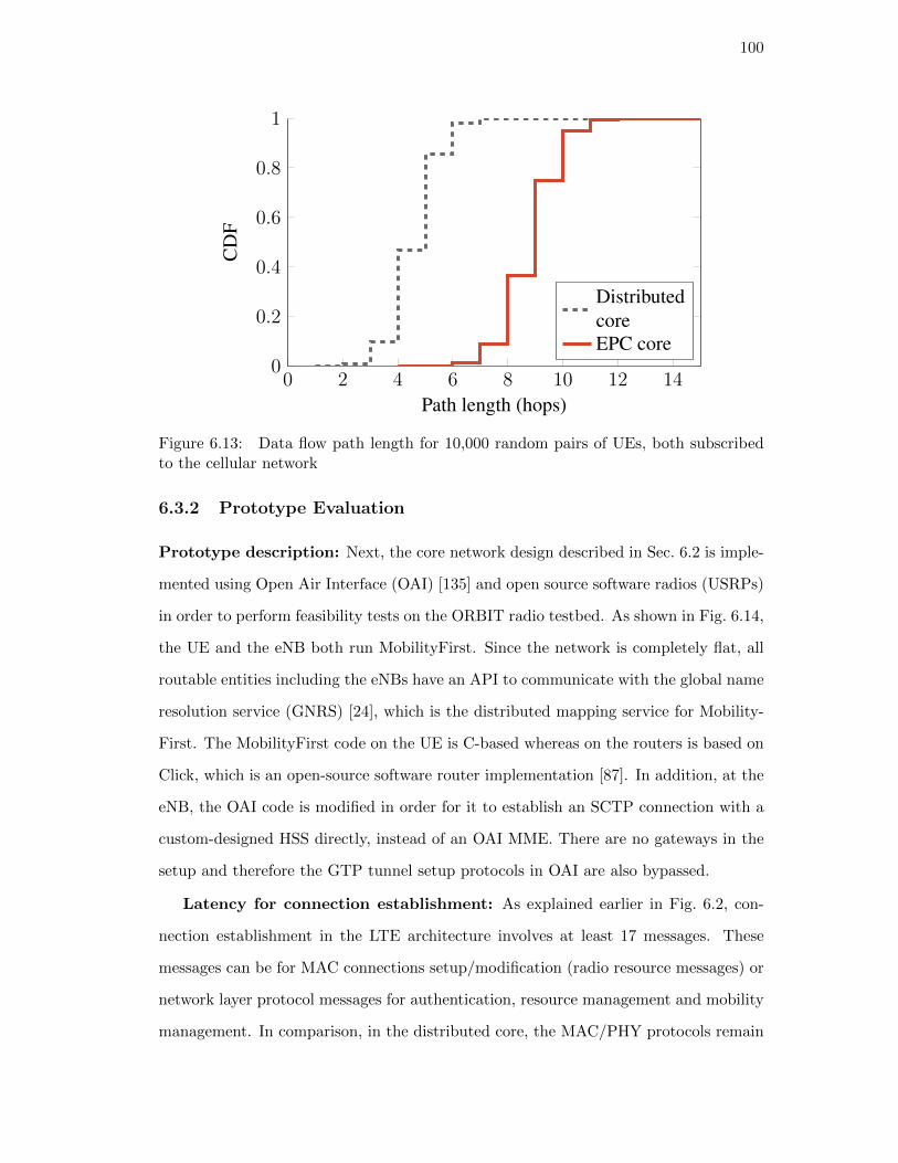
100
0 2 4 6 8 10 12 140
0.2
0.4
0.6
0.8
1
Path length (hops)
CD
F
DistributedcoreEPC core
Figure 6.13: Data flow path length for 10,000 random pairs of UEs, both subscribedto the cellular network
6.3.2 Prototype Evaluation
Prototype description: Next, the core network design described in Sec. 6.2 is imple-
mented using Open Air Interface (OAI) [135] and open source software radios (USRPs)
in order to perform feasibility tests on the ORBIT radio testbed. As shown in Fig. 6.14,
the UE and the eNB both run MobilityFirst. Since the network is completely flat, all
routable entities including the eNBs have an API to communicate with the global name
resolution service (GNRS) [24], which is the distributed mapping service for Mobility-
First. The MobilityFirst code on the UE is C-based whereas on the routers is based on
Click, which is an open-source software router implementation [87]. In addition, at the
eNB, the OAI code is modified in order for it to establish an SCTP connection with a
custom-designed HSS directly, instead of an OAI MME. There are no gateways in the
setup and therefore the GTP tunnel setup protocols in OAI are also bypassed.
Latency for connection establishment: As explained earlier in Fig. 6.2, con-
nection establishment in the LTE architecture involves at least 17 messages. These
messages can be for MAC connections setup/modification (radio resource messages) or
network layer protocol messages for authentication, resource management and mobility
management. In comparison, in the distributed core, the MAC/PHY protocols remain

101
Figure 6.14: Prototype setup for experimenting with the distributed core
unchanged, but the core network protocols are much simplified, as shown in Fig. 6.5.
In the first set of experiments, we compare network protocol related latency for con-
nection establishment. This includes the authentication and connection management
latencies but excludes the RRC related MAC layer protocol latencies. Fig. 6.15 plots
the cumulative distribution of 50 runs of an UE waking up and establishing a connection
to an eNB which is part of a distributed core, all running on a sandbox on ORBIT. As
shown in the plot, the average network layer latency incurred for the distributed core is
about 21.8 milliseconds. The same experiment is also repeated with the 4G OAI code
running on the UE and eNB and the eNB being attached to a commercial software EPC
by Amarisoft. As shown in Fig. 6.15, in this case the average network latency goes up
to 750 milliseconds. As explained earlier in Sec. 6.1, most of this latency is attributed
to the complicated set of protocols for session establishment between the eNB, MME
and the gateways.
In the next set of experiments we compare overall connection establishment latency
of the distributed core vs. a commercial network. As shown in Fig. 6.16, average
connection establishment latency (MAC protocols as well as core network protocols)
is around 49 milliseconds for the same OAI based prototype running on ORBIT. In
order to compare it to the state-of-the-art, we parsed datasets obtained from MobileIn-
sight [134] for the same US based cellular operator described in Table 6.1. Fig. 6.16

102
0.02 0.0250
0.2
0.4
0.6
0.8
1
CD
F
0.7 0.8 0.9
Latency (seconds)
Distributed coreEPC core
Figure 6.15: Experimental results for network layer latency during connection estab-lishment
plots the latency of connection establishment for 780 crowd-sourced UE datasets from
2016. As seen from the plot, the average connection establishment latency for a state-
of-the-art commercial network is around 181 milliseconds. Note that the overall latency
for the commercial system is still much lower than the full-stack software implementa-
tion of the 4G EPC system running on ORBIT. However, the distributed core network
implementation still outperforms the latency overheads seen in a commercial network.
6.4 Related Work
Works on the cellular core network architecture can be classified into three categories.
First, few works have introduced SDN in the core network to allow for flexible traffic
engineering and fine-grained policies [136, 137]. However, they assume the protocols
exchanges and the MMEs and gateways remain unchanged. The second body of work
involve virtualizing the EPC functionality [138,139], such that a software implementa-
tion of the EPC can be instantiated and migrated at will by the service provider. While
this is valuable and has promise to be used in 5G to allow multiple software cores to

103
0.02 0.05 0.1 0.25 0.5 1 5 10 200
0.2
0.4
0.6
0.8
1
Latency (seconds)
CD
FDistributed mobile coreCommerical network
Figure 6.16: Latency comparison for connection establishment in a distributed core vs.a commercial cellular network provider
share the network resources, as shown through our evaluations, the EPC core com-
ponents are themselves not scalable. Finally, recent proposals also look into smarter
backward compatible techniques that tweak part of the protocols in order to reduce
overall latency and overhead [134,140,141]. These are the ones most closely related to
our work but are complimentary, as utilizing their NFV and virtualization techniques
will provide additional latency reduction for our proposed architecture. There is also a
separate body of work on enabling IoT and low power communication in cellular [132].
However, they do not focus on low latency scenarios and are specific to low bit rate com-
munication, whereas, our proposed architecture is more generic and supports multiple
types of devices.
6.5 Summary
This work proposed a distributed core network architecture for 5G cellular systems.
The proposed architecture removes traditional gateways from the cellular core and in-
troduces a distributed mapping system for mobility management and flexible support
for newer services and heterogeneous devices, such as IoTs. Our results from a large-
scale simulation of a US-based cellular provider show significant reduction in control
overhead and smaller data-plane path lengths. The design was prototyped on com-
modity hardware and USRP radio front-ends using Click software router and Open Air

104
Interface. Experimental results were presented comparing the proposed design with
both a software LTE implementation and a US based cellular network provider, high-
lighting lower latencies for control plane setup.
105
Chapter 7
Conclusions
In this thesis we presented protocol solutions to address mobility and wireless access
requirements of future Internet-connected end-points. Utilizing the concept of named-
objects in MobilityFirst, the work focused on designing protocol solutions for i) seam-
less mobility ii) native multicast iii) disconnection-tolerance, iv) heterogeneous access,
while achieving low control overhead and reasonable scaling properties. The following
contributions were made in this thesis.
The concept of a named-object, introduced to support mobility requirements for the
future mobile Internet, was explained. A brief introduction to MobilityFirst, a named-
object architecture was provided. Detailed comparative results based on simulation was
presented contrasting MobilityFirst, with alternative name-based architectures, namely,
CCN, HIP and LISP.
An inter-domain routing protocol was proposed that takes into account both intra-
and inter-domain link quality information in order to make better routing decisions. The
proposed protocol handles endpoint mobility as well as network mobility by computing
global shortest paths based on multiple link quality metrics. Detailed simulation and
experimental results demonstrated the benefits for future mobile usecases.
Next, we described an in-network multicast tree maintenance and forwarding pro-
tocol that scales elegantly to large scale inter-domain topologies and implicitly handles
endpoint mobility. Comparison with state-of-the-art protocols showed reduced control
overhead and higher throughput on mobility.
A distributed core network architecture was presented for the future cellular mobile
core. Detailed simulation and experimental results showed reduced control overhead

106
and latency that can enable heterogeneous endpoints and applications including low-
latency IoT and AR/VR through edge-clouds.
7.1 Looking Ahead
The protocols and the open source software solutions proposed in this thesis can poten-
tially reduce the capital cost of deploying a mobile system by an order of magnitude.
There is a worldwide market for such a low cost mobile network service, particularly in
rural areas of the developing world or inner-city urban areas where there is an affordabil-
ity gap. Recognizing the fact that rural deployments tend to be backhaul bandwidth
limited, protocol solutions of multihoming, content caching, delay tolerant delivery,
edge compute can boost the effective capacity of the network. Looking forward, this
dissertation work can be extended in order for such a named-object based open source
mobile network to be plugged into the Internet to provide global connectivity at a min-
imal cost in regions with no/spotty connectivity. One of the open challenges for such
an incremental deployment is the design and thorough real-world testing of proxies and
associated protocols that can translate between MobilityFirst packets and IP and TCP
session based flows.

107
References
[1] F. Bronzino, S. Mukherjee, and D. Raychaudhuri, “The named-object abstractionfor realizing advanced mobility services in the future internet,” in Proceedings ofthe Workshop on Mobility in the Evolving Internet Architecture. ACM, 2017,pp. 37–42.
[2] T. Vu, A. Baid, H. Nguyen, and D. Raychaudhuri, “EIR: Edge-aware Interdo-main Routing Protocol for the Future Mobile Internet,” WINLAB, Tech. Rep.WINLAB-TR-414, June 2013.
[3] S. Mukherjee, F. Bronzino, S. Srinivasan, J. Chen, and D. Raychaudhuri, “Achiev-ing scalable push multicast using global name resolution,” in Proceedings of IEEEGlobecom, 2016.
[4] C. V. N. Index, “Global mobile data traffic forecast update, 2015-2020,” WhitePaper, February, 2016.
[5] C. Perkins, “Ip mobility support for ipv4,” RFC 3344, 2002.
[6] J. R. Iyengar, P. D. Amer, and R. Stewart, “Concurrent multipath transfer usingsctp multihoming over independent end-to-end paths,” Networking, IEEE/ACMTransactions on, vol. 14, no. 5, pp. 951–964, 2006.
[7] R. Moskowitz, P. Nikander, P. Jokela, and T. Henderson, “Host identity protocol,”RFC 5201, 2008.
[8] D. Meyer and D. Lewis, “The locator/id separation protocol (lisp),” IETF RFC,Tech. Rep., 2013.
[9] Ericsson, “5g radio access-reasearch and vision,” White Paper, June, 2013.
[10] Huawei, “5g: A technology vision,” White Paper, 2013.
[11] N. Solutions and Networks, “Looking ahead to 5g,” White Paper, December, 2013.
[12] V. Bychkovsky, B. Hull, A. Miu, H. Balakrishnan, and S. Madden, “A measure-ment study of vehicular internet access using in situ wi-fi networks,” in Proceedingsof the 12th annual international conference on Mobile computing and networking.ACM, 2006, pp. 50–61.
[13] Z. Fu, P. Zerfos, H. Luo, S. Lu, L. Zhang, and M. Gerla, “The impact of multihopwireless channel on tcp throughput and loss,” in INFOCOM 2003. Twenty-secondannual joint conference of the IEEE Computer and Communications. IEEE So-cieties, vol. 3. IEEE, 2003, pp. 1744–1753.
[14] Sandvine, “Sandvine 2018 Global Internet Phenomena Report,” 2018, [Online].

108
[15] G. D. Abowd, A. K. Dey, P. J. Brown, N. Davies, M. Smith, and P. Steggles,“Towards a better understanding of context and context-awareness,” in Handheldand ubiquitous computing. Springer, 1999, pp. 304–307.
[16] C. Perera, A. Zaslavsky, P. Christen, and D. Georgakopoulos, “Context awarecomputing for the internet of things: A survey,” Communications Surveys &Tutorials, IEEE, vol. 16, no. 1, pp. 414–454, 2014.
[17] T. W. Post, “Net of insecurity, a flaw in the design,” 2015, [Online].
[18] S. Kent and K. Seo, “Security Architecture for the Internet Protocol.” RFC4301, 2005.
[19] V. Chen, S. Das, L. Zhu, J. Malyar, and P. McCann, “Protocol to Access White-Space (PAWS) Databases,” Internet Draft, IETF Internet-Draft, September2014. [Online]. Available: https://tools.ietf.org/html/draft-ietf-paws-protocol-19
[20] E. U. T. R. A. Network, “X2 general aspects and principles (release 8),” TS,vol. 36, p. V8.
[21] V. Jacobson, D. K. Smetters, J. D. Thornton, M. F. Plass, N. H. Briggs, and R. L.Braynard, “Networking named content,” in Proceedings of the 5th internationalconference on Emerging networking experiments and technologies. ACM, 2009.
[22] T. Koponen, M. Chawla, B.-G. Chun, A. Ermolinskiy, K. H. Kim, S. Shenker,and I. Stoica, “A data-oriented (and beyond) network architecture,” in ACMSIGCOMM Computer Communication Review, 2007.
[23] J. Pan, R. Jain, S. Paul, and C. So-In, “Milsa: A new evolutionary architecturefor scalability, mobility, and multihoming in the future internet,” Selected Areasin Communications, IEEE Journal on, 2010.
[24] T. Vu et al., “DMap: A Shared Hosting Scheme for Dynamic Identifier to LocatorMappings in the Global Internet,” in Proceedings of ICDCS ’12, 2012.
[25] A. Sharma, X. Tie, H. Uppal, A. Venkataramani, D. Westbrook, and A. Yadav,“A global name service for a highly mobile internetwork,” in ACM SIGCOMMComputer Communication Review, vol. 44, no. 4. ACM, 2014, pp. 247–258.
[26] D. Raychaudhuri, K. Nagaraja, and A. Venkataramani, “Mobilityfirst: a robustand trustworthy mobility-centric architecture for the future internet,” ACM SIG-MOBILE Mobile Computing and Communications Review, vol. 16, no. 3, pp.2–13, 2012.
[27] F. Bronzino, K. Nagaraja, I. Seskar, and D. Raychaudhuri, “Network serviceabstractions for a mobility-centric future internet architecture,” in Proceedingsof the eighth ACM international workshop on Mobility in the evolving internetarchitecture, 2013.
[28] S. C. Nelson, G. Bhanage, and D. Raychaudhuri, “Gstar: generalized storage-aware routing for mobilityfirst in the future mobile internet,” in Proceedings ofthe sixth international workshop on MobiArch. ACM, 2011, pp. 19–24.

109
[29] A. Baid, S. Mukherjee, T. Vu, S. Mudigonda, K. Nagaraja, J. Fukuyama, andD. Raychaudhuri, “Enabling vehicular networking in the mobilityfirst future in-ternet architecture,” in 2013 IEEE 14th International Symposium on. IEEE,2013, pp. 1–3.
[30] P. Karimi, S. Mukherjee, J. Kolodziejski, I. Seskar, and D. Raychaudhuri, “Mea-surement based mobility emulation platform for next generation wireless net-works,” in IEEE INFOCOM 2018-IEEE Conference on Computer Communica-tions Workshops (INFOCOM WKSHPS). IEEE, 2018, pp. 330–335.
[31] S. Mukherjee, A. Baid, I. Seskar, and D. Raychaudhur, “Network-assisted multi-homing for emerging heterogeneous wireless access scenarios,” in Proceedings ofIEEE PIMRC 2014. IEEE, 2014.
[32] P. Karimi and D. Raychaudhuri, “Achieving high- performance cellular data ser-vices with multi-network access,” in Proceedings of IEEE Globecom, 2016.
[33] Y. Rekhter, T. Li, and S. Hares, “A border gateway protocol 4 (bgp-4),” in IETFRFC 4271, 2005.
[34] M. Caesar and J. Rexford, “Bgp routing policies in isp networks,” IEEE network,vol. 19, no. 6, pp. 5–11, 2005.
[35] M. Satyanarayanan, “Mobile computing: the next decade,” ACM SIGMOBILEMobile Computing and Communications Review, vol. 15, no. 2, pp. 2–10, 2011.
[36] L. Zhang, A. Afanasyev, J. Burke, V. Jacobson, P. Crowley, C. Papadopoulos,L. Wang, B. Zhang et al., “Named data networking,” ACM SIGCOMM ComputerCommunication Review, vol. 44, no. 3, pp. 66–73, 2014.
[37] A. Anand, F. Dogar, D. Han, B. Li, H. Lim, M. Machado, W. Wu, A. Akella,D. G. Andersen, J. W. Byers et al., “XIA: An Architecture for an Evolvable andTrustworthy Internet,” in HotNets, 2011.
[38] A. Hoque, S. O. Amin, A. Alyyan, B. Zhang, L. Zhang, and L. Wang, “Nlsr:named-data link state routing protocol,” in Proceedings of the 3rd ACM SIG-COMM workshop on Information-centric networking. ACM, 2013, pp. 15–20.
[39] A. Gupta, L. Vanbever, M. Shahbaz, S. P. Donovan, B. Schlinker, N. Feamster,J. Rexford, S. Shenker, R. Clark, and E. Katz-Bassett, “Sdx: A software definedinternet exchange,” ACM SIGCOMM Computer Communication Review, vol. 44,no. 4, pp. 551–562, 2015.
[40] “Project Fi,” https://fi.google.com, Accessed: 2017-06-23.
[41] “Republic Wireless,” https://republicwireless.com/, Accessed: 2017-06-23.
[42] P. Rodriguez, R. Chakravorty, J. Chesterfield, I. Pratt, and S. Banerjee, “Mar: Acommuter router infrastructure for the mobile internet,” in Proceedings of the 2ndinternational conference on Mobile systems, applications, and services. ACM,2004, pp. 217–230.
110
[43] D. S. Phatak and T. Goff, “A novel mechanism for data streaming across multipleip links for improving throughput and reliability in mobile environments,” inINFOCOM 2002. Twenty-First Annual Joint Conference of the IEEE Computerand Communications Societies. Proceedings. IEEE, vol. 2. IEEE, 2002, pp. 773–781.
[44] B. Augustin, B. Krishnamurthy, and W. Willinger, “Ixps: mapped?” in Proceed-ings of the 9th ACM SIGCOMM conference on Internet measurement conference.ACM, 2009, pp. 336–349.
[45] “Long-Range 802.11n (5GHz) Wi-Fi Backhaul,” https://www.ruckuswireless.com/products/access-points/zoneflex-outdoor, Accessed: 2017-06-23.
[46] “Project Loon,” https://x.company/loon/, Accessed: 2017-06-23.
[47] B. Abarbanel, “Implementing global network mobility using bgp,” in NANOGPresentation, 2004.
[48] H. Ballani and P. Francis, “Towards a global ip anycast service,” in ACM SIG-COMM Computer Communication Review, vol. 35, no. 4. ACM, 2005, pp. 301–312.
[49] J. S. Silva, T. Camilo, A. Rodrigues, M. Silva, F. Gaudencio, and F. Boavida,“Multicast in wireless sensor networks the next step,” in In Proceeding of IEEEISWPC 2007. IEEE, 2007.
[50] C. R. K. D. Bates, T and Y. Rekhter, “Multiprotocol Extensions for BGP-4, RFC4760,” 2007.
[51] S. Saroiu, K. P. Gummadi, R. J. Dunn, S. D. Gribble, and H. M. Levy, “Ananalysis of internet content delivery systems,” ACM SIGOPS Operating SystemsReview, vol. 36, no. SI, pp. 315–327, 2002.
[52] D. G. Andersen, H. Balakrishnan, N. Feamster, T. Koponen, D. Moon, andS. Shenker, “Accountable internet protocol (aip),” in ACM SIGCOMM Com-puter Communication Review, vol. 38, no. 4. ACM, 2008, pp. 339–350.
[53] D. Saucez, L. Iannone, and B. Donnet, “A first measurement look at the de-ployment and evolution of the locator/id separation protocol,” ACM SIGCOMMComputer Communication Review, vol. 43, no. 2, pp. 37–43, 2013.
[54] C. Kim, M. Caesar, and J. Rexford, “Floodless in seattle: a scalable ethernetarchitecture for large enterprises,” in ACM SIGCOMM Computer CommunicationReview, vol. 38, no. 4. ACM, 2008, pp. 3–14.
[55] Y. Wang, I. Avramopoulos, and J. Rexford, “Design for configurability: rethink-ing interdomain routing policies from the ground up,” Selected Areas in Commu-nications, IEEE Journal on, vol. 27, no. 3, pp. 336–348, 2009.
[56] D. Walton, A. Retana, E. Chen, and J. Scudder, “Advertisement of MultiplePaths in BGP,” in IETF RFC 7911, 2016.

111
[57] A. F. T. Committee, “Private network-network interface specification,” Version1.0 (PNNI), 1996.
[58] J. Moy, “Ospf version 2,” in IETF RFC 2328, 1998.
[59] P. Godfrey, I. Ganichev, S. Shenker, and I. Stoica, “Pathlet routing,” in ACMSIGCOMM Computer Communication Review, vol. 39, no. 4. ACM, 2009, pp.111–122.
[60] L. Subramanian, S. Agarwal, J. Rexford, and R. H. Katz, “Characterizing theinternet hierarchy from multiple vantage points,” in INFOCOM 2002. IEEE,2002.
[61] L. Gao, “On inferring autonomous system relationships in the internet,”IEEE/ACM Transactions on Networking (ToN), vol. 9, no. 6, pp. 733–745, 2001.
[62] “The CAIDA UCSD Internet Topology Data Kit,” http://www.caida.org/data/internet-topology-data-kit, Accessed: 2017-06-23.
[63] B. Quoitin and S. Uhlig, “Modeling the routing of an autonomous system withc-bgp,” Network, IEEE, vol. 19, no. 6, pp. 12–19, 2005.
[64] U. Meyer and P. Sanders, “δ-stepping: A parallel single source shortest pathalgorithm,” in AlgorithmsESA98. Springer, 1998.
[65] A. Crauser, K. Mehlhorn, U. Meyer, and P. Sanders, “A parallelization of dijk-stra’s shortest path algorithm,” in Mathematical Foundations of Computer Sci-ence 1998. Springer, 1998.
[66] N. Edmonds, A. Breuer, D. Gregor, and A. Lumsdaine, “Single-source shortestpaths with the parallel boost graph library,” The Ninth DIMACS ImplementationChallenge: The Shortest Path Problem, 2006.
[67] P. Guangyu, G. Mario, and C. Tsu-Wei, “Fisheye state routing in mobile ad hocnetworks,” in Proc. of ICC, 2000.
[68] B. S. Davie and Y. Rekhter, MPLS: technology and applications. Morgan Kauf-mann Publishers Inc., 2000.
[69] A. Beben, “Eq-bgp: an efficient inter-domain qos routing protocol,” in AdvancedInformation Networking and Applications, 2006. AINA 2006. 20th InternationalConference on, vol. 2. IEEE, 2006, pp. 5–pp.
[70] T. Braun, M. Diaz, J. E. Gabeiras, and T. Staub, End-to-end quality of serviceover heterogeneous networks. Springer Science & Business Media, 2008.
[71] Q. Li, J. Beaver, A. Amer, P. K. Chrysanthis, A. Labrinidis, and G. Santhanakr-ishnan, “Multi-criteria routing in wireless sensor-based pervasive environments,”International Journal of Pervasive Computing and Communications, vol. 1, no. 4,pp. 313–326, 2005.
[72] X. Chen, H. Cai, and T. Wolf, “Multi-criteria routing in networks with pathchoices,” in Network Protocols (ICNP), 2015 IEEE 23rd International Conferenceon. IEEE, 2015, pp. 334–344.

112
[73] R. Teixeira, A. Shaikh, T. Griffin, and J. Rexford, “Dynamics of hot-potatorouting in ip networks,” ACM SIGMETRICS Performance Evaluation Review,vol. 32, no. 1, pp. 307–319, 2004.
[74] K. Su, F. Bronzino, K. Ramakrishnan, and D. Raychaudhur, “Mftp: A clean-slate transport protocol for the information centric mobilityfirst network,” inProceedings of ACM ICN 2015. ACM, 2015.
[75] S. Y. Qiu, P. D. McDaniel, and F. Monrose, “Toward valley-free inter-domainrouting,” in IEEE ICC. IEEE, 2007.
[76] “Education Roaming (eduroam),” https://www.eduroam.org/, Accessed: 2017-06-23.
[77] A. Lara, S. Mukherjee, B. Ramamurthy, D. Raychaudhuri, and K. Ramakrish-nan, “Inter-domain routing with cut-through switching for the mobilityfirst futureinternet architecture,” in Communications (ICC), 2016 IEEE International Con-ference on. IEEE, 2016, pp. 1–6.
[78] “Netflix Open Connect,” https://openconnect.netflix.com/, Accessed: 2017-06-23.
[79] X. Yang, D. Clark, and A. W. Berger, “Nira: a new inter-domain routing ar-chitecture,” IEEE/ACM Transactions on Networking (ToN), vol. 15, no. 4, pp.775–788, 2007.
[80] W. Xu and J. Rexford, MIRO: multi-path interdomain routing. ACM, 2006,vol. 36, no. 4.
[81] S. Mukherjee, S. Sriram, T. Vu, and D. Raychaudhuri, “Eir: Edge-aware inter-domain routing protocol for the future mobile internet,” Computer Networks, vol.127, pp. 13–30, 2017.
[82] Y. Shavitt and E. Shir, “Dimes: Let the internet measure itself,” ACM SIG-COMM Computer Communication Review, vol. 35, no. 5, pp. 71–74, 2005.
[83] G. Siganos, S. L. Tauro, and M. Faloutsos, “Jellyfish: A conceptual model for theas internet topology,” Journal of Communications and Networks, vol. 8, no. 3,pp. 339–350, 2006.
[84] M. Li, D. Agrawal, D. Ganesan, A. Venkataramani, and H. Agrawal, “Block-switched networks: A new paradigm for wireless transport.” in NSDI, vol. 9,2009, pp. 423–436.
[85] “CIDR-Report,” http://www.cidr-report.org/as2.0/, Accessed: 2017-06-23.
[86] “How much memory should I have in my router to receive the complete BGProuting table from my ISP?” http://www.cisco.com/c/en/us/support/docs/ip/border-gateway-protocol-bgp/5816-bgpfaq-5816.html#anc20, Accessed: 2017-06-23.
[87] E. Kohler, R. Morris, B. Chen, J. Jannotti, and M. F. Kaashoek, “The click mod-ular router,” ACM Transactions on Computer Systems (TOCS), vol. 18, no. 3,pp. 263–297, 2000.

113
[88] D. Raychaudhuri, I. Seskar, M. Ott, S. Ganu, K. Ramachandran, H. Kremo,R. Siracusa, H. Liu, and M. Singh, “Overview of the orbit radio grid testbedfor evaluation of next-generation wireless network protocols,” in Wireless Com-munications and Networking Conference, 2005 IEEE, vol. 3. IEEE, 2005, pp.1664–1669.
[89] Z. Gao, A. Venkataramani, J. F. Kurose, and S. Heimlicher, “Towards a quan-titative comparison of location-independent network architectures,” ACM SIG-COMM Computer Communication Review, vol. 44, no. 4, pp. 259–270, 2015.
[90] “SFMTA Municipal Transport Agency,” https://www.sfmta.com/, Accessed:2017-06-23.
[91] M. Motiwala, M. Elmore, N. Feamster, and S. Vempala, “Path splicing,” in ACMSIGCOMM Computer Communication Review, vol. 38, no. 4. ACM, 2008, pp.27–38.
[92] X. Yang and D. Wetherall, “Source selectable path diversity via routing deflec-tions,” in ACM SIGCOMM Computer Communication Review, vol. 36, no. 4.ACM, 2006, pp. 159–170.
[93] F. Wang and L. Gao, “Path diversity aware interdomain routing,” in INFOCOM2009, IEEE. IEEE, 2009, pp. 307–315.
[94] P. Verkaik, D. Pei, T. Scholl, A. Shaikh, A. C. Snoeren, and J. E. Van Der Merwe,“Wresting control from bgp: Scalable fine-grained route control.” in USENIXAnnual Technical Conference, 2007, pp. 295–308.
[95] D. Walton, A. Retana, E. Chen, and J. Scudder, “Advertisement of multiple pathsin bgp,” in IETF RFC 7911, 2016.
[96] M. P. Howarth, M. Boucadair, P. Flegkas, N. Wang, G. Pavlou, P. Morand,T. Coadic, D. Griffin, A. Asgari, and P. Georgatsos, “End-to-end quality of ser-vice provisioning through inter-provider traffic engineering,” Computer Commu-nications, vol. 29, no. 6, pp. 683–702, 2006.
[97] C. Filsfils, N. K. Nainar, C. Pignataro, J. C. Cardona, and P. Francois, “Thesegment routing architecture,” in Global Communications Conference (GLOBE-COM), 2015 IEEE. IEEE, 2015, pp. 1–6.
[98] L. Subramanian, M. Caesar, C. T. Ee, M. Handley, M. Mao, S. Shenker, andI. Stoica, “Hlp: a next generation inter-domain routing protocol,” in ACM SIG-COMM Computer Communication Review, vol. 35, no. 4. ACM, 2005, pp. 13–24.
[99] D. Farinacci, C. Liu, S. Deering, D. Estrin, M. Handley, V. Jacobson, L. Wei,P. Sharma, D. Thaler, and A. Helmy, “Protocol independent multicast-sparsemode (pim-sm): Protocol specification,” 1998.
[100] J. Moy, “Rfc 1584–multicast extensions to ospf,” SRI Network Information Cen-ter, 1994.
114
[101] C. Diot, B. N. Levine, B. Lyles, H. Kassem, and D. Balensiefen, “Deploymentissues for the ip multicast service and architecture,” Network, IEEE, vol. 14, no. 1,pp. 78–88, 2000.
[102] D. Meyer and B. Fenner, “Multicast source discovery protocol (msdp),” 2003.
[103] P. Radoslavov, D. Estrin, R. Govindan, M. Handley, S. Kumar, and D. Thaler,“The multicast address-set claim (masc) protocol, rfc-2909,” Tech. Rep., 2000.
[104] M. Castro, P. Druschel, A.-M. Kermarrec, and A. I. Rowstron, “SCRIBE:A Large-Scale and Decentralized Application-Level Multicast Infrastructure,”JSAC, pp. 1489–1499, 2002.
[105] D. A. Tran, K. Hua, and T. Do, “ZIGZAG: An Efficient Peer-to-Peer Scheme forMedia Streaming,” in INFOCOM, 2003.
[106] K. Bharath-Kumar and J. M. Jaffe, “Routing to multiple destinations in computernetworks,” Communications, IEEE Transactions on, 1983.
[107] C. Labovitz, A. Ahuja, A. Bose, and F. Jahanian, “Delayed internet routingconvergence,” ACM SIGCOMM Computer Communication Review, vol. 30, no. 4,pp. 175–187, 2000.
[108] S. Mukherjee, F. Bronzino, S. Srinivasan, J. Chen, and D. Raychaudhuri, “Achiev-ing scalable push multicast services using global name resolution,” in Global Com-munications Conference (GLOBECOM), 2016 IEEE. IEEE, 2016, pp. 1–6.
[109] A. Baid, T. Vu, and D. Raychaudhuri, “Comparing alternative approaches fornetworking of named objects in the future internet,” in Proceedings of ComputerCommunications Workshops. IEEE, 2012.
[110] J. Laganier and L. Eggert, “Host identity protocol (hip) rendezvous extension,”RFC 5204, 2008.
[111] C. White, D. Lewis, D. Meyer, and D. Farinacci, “Lisp mobile node,” draft-meyer-lisp-mn-08, Internet Engineering Task Force, 2016.
[112] V. Fuller, D. Farinacci, D. Meyer, and D. Lewis, “Lisp alternative topology(lisp+alt),” draft-ietf-lisp-alt-01, Internet Engineering Task Force, 2011.
[113] G. Carofiglio, M. Gallo, L. Muscariello, M. Papalini, and S. Wang, “Optimalmultipath congestion control and request forwarding in information-centric net-works,” in Proceedings of the eighth ACM international workshop on Mobility inthe evolving internet architecture, 2013.
[114] J. Chen, M. Arumaithurai, L. Jiao, X. Fu, and K. K. Ramakrishnan, “COPSS:An Efficient Content Oriented Pub/Sub System,” in ANCS, 2011.
[115] X. Zhu and J. W. Atwood, “A secure multicast model for peer-to-peer and accessnetworks using the host identity protocol,” in Proceedings of P2PM. IEEE, 2007.
[116] D. Farinacci et al., “The locator/id separation protocol (lisp) for multicast envi-ronments, rfc 6831,” 2013.

115
[117] M. Piorkowski, N. Sarafijanovic-Djukic, and M. Grossglauser, “CRAWDADdataset epfl/mobility (v. 2009-02-24),” Feb. 2009.
[118] WiGLE - Wireless Geographic Logging Engine, http://wigle.net/, 2016.
[119] N. Basher, A. Mahanti, A. Mahanti, C. Williamson, and M. Arlitt, “A compara-tive analysis of web and peer-to-peer traffic,” in Proceedings of WWW. ACM,2008.
[120] A. C. S. O. A. A. A. G. W. Ravi Ravindran, Prakash Suthar, “Deploying icn in3gpps 5g nextgen core architecture,” in Proc. of IEEE, 5G World Forum, 2018.
[121] 3GPP, “System Architecture for the 5G System.” TS 23.501 v15.3.0, 2018.
[122] T. ETSI, “129 281 V9. 3.0 (2010-06) Technical Specification, GPRS TunnellingProtocol for User Plane (GTPv1- U),” Universal Mobile Telecommunications Sys-tem (UMTS), 2010.
[123] Q. Xu, J. Huang, Z. Wang, F. Qian, A. Gerber, and Z. M. Mao, “Cellular datanetwork infrastructure characterization and implication on mobile content place-ment,” in Proceedings of the ACM SIGMETRICS joint international conferenceon Measurement and modeling of computer systems. ACM, 2011, pp. 317–328.
[124] J. Huang, F. Qian, A. Gerber, Z. M. Mao, S. Sen, and O. Spatscheck, “A closeexamination of performance and power characteristics of 4g lte networks,” inProceedings of the 10th international conference on Mobile systems, applications,and services. ACM, 2012, pp. 225–238.
[125] 3GPP, “Cellular system support for ultra-low complexity and low throughputinternet of things (CIoT).” TR 45.820, 2015.
[126] R. D. Yates and W. Lehr, “Mobilityfirst, lte and the evolution of mobile net-works,” in Dynamic Spectrum Access Networks (DYSPAN), 2012 IEEE Interna-tional Symposium on. IEEE, 2012, pp. 180–188.
[127] Y. Hu, R. D. Yates, and D. Raychaudhuri, “A Hierarchically Aggregated In-Network Global Name Resolution Service for the Mobile Internet,” in WINLABTR 442, 2015.
[128] T. Herbert and P. Lapukhov, “Identifier-locator addressing for ipv6,” draft-herbert-intarea-ila-01 (work in progress), 2018.
[129] 3GPP, “Study on enhancement of EPC for low latency communication includingdevice mobility.” TR 23.739, 2018.
[130] S. Mukherjee, R. Ravindran, and D. Raychaudhuri, “A distributed core networkarchitecture for 5g systems and beyond,” in Proceedings of the 2018 Workshop onNetworking for Emerging Applications and Technologies. ACM, 2018, pp. 33–38.
[131] statista, “Wireless subscriptions market share by carrier in the u.s. from 1st quar-ter 2011 to 4th quarter 2017,” 2018, accessed: 2018-06-08.
[132] G. T. . V13.1.0, “cellular system support for ultra-low complexity and lowthroughput internet of things (ciot),” 2015.

116
[133] unwiredlabs, “The world’s largest open database of cell towers,” 2018, accessed:2018-06-08.
[134] Y. Li, C. Peng, Z. Yuan, J. Li, H. Deng, and T. Wang, “Mobileinsight: Extractingand analyzing cellular network information on smartphones,” in Proceedings ofthe 22nd Annual International Conference on Mobile Computing and Networking.ACM, 2016, pp. 202–215.
[135] N. Nikaein, M. K. Marina, S. Manickam, A. Dawson, R. Knopp, and C. Bon-net, “Openairinterface: A flexible platform for 5g research,” ACM SIGCOMMComputer Communication Review, vol. 44, no. 5, pp. 33–38, 2014.
[136] X. Jin, L. E. Li, L. Vanbever, and J. Rexford, “Softcell: Scalable and flexiblecellular core network architecture,” in Proceedings of the ninth ACM conferenceon Emerging networking experiments and technologies. ACM, 2013, pp. 163–174.
[137] M. Moradi, W. Wu, L. E. Li, and Z. M. Mao, “Softmow: Recursive and reconfig-urable cellular wan architecture,” in Proceedings of the 10th ACM Internationalon Conference on emerging Networking Experiments and Technologies. ACM,2014, pp. 377–390.
[138] Z. A. Qazi, P. K. Penumarthi, V. Sekar, V. Gopalakrishnan, K. Joshi, and S. R.Das, “Klein: A minimally disruptive design for an elastic cellular core,” in Pro-ceedings of the Symposium on SDN Research. ACM, 2016, p. 2.
[139] A. Basta, W. Kellerer, M. Hoffmann, K. Hoffmann, and E.-D. Schmidt, “A virtualsdn-enabled lte epc architecture: A case study for s-/p-gateways functions,” inFuture Networks and Services (SDN4FNS), 2013 IEEE SDN for. IEEE, 2013,pp. 1–7.
[140] A. Mohammadkhan, K. Ramakrishnan, A. S. Rajan, and C. Maciocco, “Cleang:A clean-slate epc architecture and controlplane protocol for next generation cel-lular networks,” in Proceedings of the 2016 ACM Workshop on Cloud-AssistedNetworking. ACM, 2016, pp. 31–36.
[141] Z. A. Qazi, M. Walls, A. Panda, V. Sekar, S. Ratnasamy, and S. Shenker, “A highperformance packet core for next generation cellular networks,” in Proceedingsof the Conference of the ACM Special Interest Group on Data Communication.ACM, 2017, pp. 348–361.