Embed Size (px)
Citation preview

c I C . ' .
--- - /- ,,- ,,
(-GEORGE H. LUDWIG) Project Scientist for the Eccentric Orbiting Geophysical Obserb*atories
Space Sciences Division. Goddard Space Flighi Center, Greenbelt, Maryland, U.S. A.
(Received April 4, 1963)
/ 5- 53-9 - 1 Abstract. The Orbiting Geophysical Observatories and the supporting ground checkout equipment, data acquisition and tracking stations and data processing equipment are designed to conduct large numbers of diverse experiments in space. Measurements will be made within the earth's atmosphere, ionosphere, exosphere, magnetosphere, and in cislunar space to obtain a better understanding of earth-sun relationships and of the earth as a planet. Configured to meet scientific requirements, the observatories include six booms to support detectors away from disturbances generated in the main body. Five degrees of freedom allow the orientation of experiments relative to three references - the earth, the sun, and the orbital plane. Power, thermal control, and data handling subsystems provide for the proper operation of the experiments and telemetry of the data. Ground stations receive these data, which are then processed into a form suitable for use by the experimenters. The systems have been designed to make available a standard spacecraft and support equipment which can be used repeatedly to carry large numbers of easily integrated experiments in a wide variety of orbits. -
Introduction
During the five years since the launching of the first artificial earth satellite, the satellite systems have passed through a rapid evolutionary process. For investigations in the space sciences, two principal satellite types are now in use. The first is the relatively small satellite which includes the Explorer series, the Vanguard series, the State University of Iowa Injun series, the Naval Research Laboratory Lofti and Solar Radiation series, and the international program Ariel and Alouette series. These spacecraft, in general, contain sets of directly related experiments, usually provided by a small number of laboratories or, in a few cases, a single laboratory. The second type is the comparatively large orbiting observatory. Three observatory series are now in cse cr p!ar,ned, the Orbiting Solar Observarory (OSO), the Orbiting Geo- physical Observatory (OGO) which is described in this paper, and the Orbiting Astronomical Observatory (OAO). These standard spacecraft are designed to carry large numbers of easily installed experiments of a somewhat more diverse nature.
'
A. THE SMALL, EXPLORER TYPE SATELLITES
The first of the Explorer type satellites were necessarily quite light-weight and simple because of the limitations of the launch vehicles and the desire for reliability in a new technology. As larger launch vehicles such as the Delta became available, the weight and size of these spacecraft increased. And as we have become more experienced, the complexity of the spacecraft has tended to increase to provide a greater amount of information from each launching. We may expect to see a continuation of the use of
https://ntrs.nasa.gov/search.jsp?R=19640005640 2018-08-22T04:37:11+00:00Z

176
. . . . . a
GEORGE H. LUDWIG
the larger and more complex observatories. These advantages may be summarized: 1. Some experiments may require satellite orbits into which the larger observa-
tories cannot be placed due to launch vehicle limitations. Or a sufficiently large number of experiments may not require a particular orbit to warrant the use of an observatory.
2. The experiments may require a different spatial orientation than is contemplated for any of the larger observatories. For example, a spin stabilized satellite may be more suitable for certain experiments which need to rapidly scan on the celestial sphere. Magnetic field orientation may be preferred for certain groups of charged- particle experiments.
3. Some classes of very sensitive experiments may require small satellites to avoid contamination or interference from the satellite structure, power and electronic subsystems, or other experiments.
4. It is possible to launch a small satellite with a very short lead time for the high priority investigation of new phenomena. At the present time this is feasible only under exceptional circumstances. An example is the launching of Explorer XV for the investigation of the high flux of geomagnetically trapped particles injected by the Starfish high altitude nuclear explosion in the summer of 1962.
5. During the early phases of the observatory program the reliability of the small satellites may be higher than that of the observatories. This advantage may disappear later because the larger weight capability of the observatories permits the inclusion of a higher degree of redundancy, and because the repeated use of the standard observatory designs should lead to a continuous increase in reliability. This point is speculative at this time, since only one observatory has been launched (OSO-1). Interestingly, its operating lifetime has been longer than the average lifetimes of the recent Explorer type satellites.
6. A number of experimenters feel that the small satellite with its simple telemetry system and spin or magnetic field stabilization offers them a more nearly ideal tool for research and university student training, in that they are able to retain more direct control over their own investigations. The organizational structure is simpler for the smaller satellite programs, and less effort is required for liaison with other groups and for the planning of the operational aspects such as the prelaunch testing and data processing. This is correct at the present time. Whether it will continue to be true when the observatory programs have progressed further remains to be seen.
B. THE OBSERVATORIES
The small, satellites, as a rule, have tended to be highly integrated mechanically, thermally, and electrically in order to take full advantage of the launch vehicle capability; i.e., they were built as tightly knit, homogeneous assemblies. To illustrate, it was necessary to almost completely disassemble the Explorer I and Pioneer IV spacecraft in order to change the batteries. This situation has steadily improved with the availability of the Delta launch vehicle, and the internal satellite systems have tended to become separated into more easily changeable subassemblies. But a modera- tely high degree of electronic system integration is still employed. This means that

THE ORBITING GEOPHYSICAL OBSERVATORIES 177
the spacecraft will continue to be essentially one-mission systems in the sense that extensive redesign of the subsystems will1 be nec&sary to accommodate each new set
As the larger launching vehicles such as the Thor-Agena and Atlas-Agena have become available, it has become possible to launch heavier experiments and larger numbers of small experiments. In addition, it has become possible to increase the capabilities of the data handling, power, and thermal subsystems to allow greater flexibility. And solar, earth, and inertial reference attitude control systems have become feasible. It has become possible to establish well defined, standard, electrical and mechanical interfaces between the experiments and the various spacecraft sub- systems. Thus, the concept of a family of standard observatories has evolved. These spacecraft are standard in the sense that they present a well defined set of interfaces to the experiments and are highly flexible in order to accommodate many types of experiments. It should not be necessary to design and develop a new spacecraft for each mission, instead a spacecraft design can be used repeatedly with only minor modifications to carry different combinations of experiments on successive missions.
The advantages of the standard observatory concept, in addition to those discussed above, include the following:
1. Large numbers of directly and indirectly related experiments can be performed concurrently to study the correlations between several phenomena at given positions in space. For example, with the OGO it will be possible to study simultaneously the relationships between solar events, the solar plasma, the earth's trapped radiation belts, the earth's magnetic field, and the atmospheric structure.
2. Alternately, a few heavy or bulky instruments can be launched to perform more extensive? complex, or detailed observations. The OGO will be able to carry a single large, earth oriented experiment weighing more than 68 kg.
3. The electrical, mechanical, and thermal interfaces between the experiments and spacecraft subsystems are well-defined and will remain essentially fixed from mission to mission. It should be possible to avoid difficulties encountered in previous projects when the experirhents and spacecraft were developed concurrently without benefit of previousiy existing definitions of the interfaces between them. The subsystems have been designed with.enough flexibility so that they should not seriously limit the evolu- tion of experiment technology for some time.
4. The system reliability should be ultimately improved by the repeated use and stepwise improvement of a basic design, and by the fact that the larger weight allot- ment will permit a higher degree of redundancy.
5. Continued use of a standard spacecraft design should lead to higher operating efficiency through the continuous evolution and use of a ground data acquisition and tracking station network, data processing equipment, and operating procedures. The use of the larger spacecraft will reduce the total operational load since a given number of experiments will be carried on a smaller number of spacecraft.
6 . In spite of the rather high initial development cost of the observatories, the ultimate cost of orbiting a given weight of experiments should be lower than if they
, of experiments. ..(
.
-

178 GEORGE H. LUDWIG
were carried on a greater number of small satellites, since the development of a new spacecraft for each new mission will be avoided.
The OGO Project
The Orbiting Geophysical Observatory project includes the development and use of the experiments and spacecraft which make up the observatory, the ground checkout equipment, the complex of ground receiving and tracking stations, and the data processing equipment. It is a part of the NASA space sciences long range program. The NASA Headquarters and the Goddard Space Flight Center, located at Greenbelt, Maryland, share the responsibility for the original formulation of the concept and the statement of the general objectives. The management of the project is a responsi- bility of the Goddard Space Flight Center. The project manager is responsible to the director of the center in the carrying out of this responsibility. The project scientist works very closely with the manager to ensure that the scientific objectives are met. He serves as the main scientific contact with the experimenters and monitors the development of the spacecraft and data handling systems so that the requirements of the experimenters can best be met. The ground systems manager also works directly with the project manager to ensure that the tracking, data acquisition, and data processing needs will be met.
Once the experiments for each launching are selected by NASA headquarters, contracts are written by Goddard for the financial support of the experimenter’s efforts. The experimenters are furnished with necessary technical information to enable them to design their instruments, to plan for their integration and testing, and for data processing after launch. Beyond this, the experimenters retain the responsi- bility for delivering to Goddard finished experiments which will meet their initial objectives and which will survive the environmental tests.
The experimenters also retain primary responsibility for the processing and analysis of the data obtained from their experiments. They will receive digital computer tapes containing the raw data in cleaned and sorted but otherwise un- processed form from their own experiments and the necessary housekeeping and timing information. A different set of tapes will contain the orbit and observatory orientation information. The experimenters arrange for their own computer programming, processing, tabulation, analysis, etc. in keeping with the belief that the typical investigator prefers to retain direct control over this phase of the opera- tion.
Orbits and experiments have been chosen for the first two OGO missions. The first observatory, designated OGO-A and sometimes referred to as the Eccentric Orbiting Geophysical Observatory (EGO) will be launched by an Atlas-Agena B in mid 1964 from the Atlantic Missile Range into a highly eccentric orbit having initial perigee and apogee heights of 280 and 110 000 km above the earth, respectively, and an initial orbital inclination of approximately 31 degrees. The second will be launched into a near-polar orbit in late 1964, and is known as the OGO-B or Polar
.
-
3

THE ORBITING GEOPHYSICAL OBSERVATORKS 179
Orbiting Geophysical Observatory (POGO). The launching will occur with a Thor- Agena from the Pacific Missile Range. The POGO orbit will have perigee and apogee heights of 250 and 920 km above the earth.
Description of the Spacecraft
The Orbiting Geophysical Observatory consists of two parts, the experiments and the spacecraft. The spacecraft is being designed and built by the Space Technology Laboratories, Inc. of Redondo Beach. California. It consists of a basic structure to
Fig. 1. The Orbiting Geophysical Observatory. The distance from tip to tip of the long booms is about 17.7 m. The distance between ends of the solar panels is about 6.0 m. The appendages are
configured for the first flight.
support and enclose the experiments and other assemblies, an attitude stabilization UUlU llUllU11116, C"...,.,L...~.uL,W"") U l l U L 1 L ~ 1 1 . 1 ~ 1 _"*1&.Wl O W "
systems for servicing the experiments. The weight of the spacecraft is approximately 394 kg, and it is designed to accommodate about 76 kg of experiments, making a total observatory weight of about 470 kg.
subsystem, and power, A n t o h 0 n A l ; n n nnmm rn;,--t;nnr o n r l thnrmol n n n t r n l c ~ ~ k
A. CONFIGURATION
The external configuration of the deployed observatory is shown in the drawing of Figure 1. The central box structure measures 1.70 m long by 0.78 m high by 0.81 m wide. Its size was chosen to provide a large internal volume to accommodate an assortment of large or irregularly shaped experiments in addition to the spacecraft subsystem components. It was limited, however, by the requirement that it fit within the standard nose fairing for the Agena rocket. The action of the attitude control system causes one of the 0.81 m by 1.70 m faces of the main body to face the earth at all times. Experiments which require earth orientation are mounted on this face, and those requiring orientation away from the earth are located on the opposite side.

180 GEORGE H. LUDWIG
The solar panels which provide the electrical power for the observatory are mounted on a shaft which passes through the main body. The attitude control system orients the silicon solar cells mounted on these panels toward the sun by controlling the rotation of the main body about the earth-observatory axis and by controlling
Fig. 2. The Observatory in its folded configuration. The structural design model with generalized appendage experiment containers is mounted on the vibration table for one of the two transverse vibration tests. Only a few of the thermal control louvers are mounted, and none of the solar cells are in place. The main body is mounted on the adapter by which it will be attached to the Agena rocket.
(Photo courtesy of Space Technology Laboratories).
the rotation of the solar panels about their shaft axis. Enclosures located on each solar panel contain experiments requiring a fixed orientation with respect to the sun. The orientation of the solar panels toward the sun results in the orientation, at right angles to the observatory-sun line, of the two main body faces through which the shaft passes. Thus, these two faces are never illuminated by the sun, and are used to radiate excess heat from the observatory.
THE ORBITING GEOPHYSICAL OBSERVATORIES 181
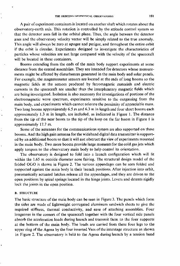
A pair of experiment containers is located on another shaft which rotates about the observatory-earth axis. This rotation is controlled by the attitude control system so that the detector axes fall in the orbital plane. Thus, the angle between the detector axes and the observatory velocity vector will be simply related to the true anomaly. This angle will always be zero at apogee and perigee, and throughout the entire orbit if the orbit is circular. Experiments designed to investigate the characteristics of particles whose velocities are not large compared with the velocity of the spacecraft will be located in these containers.
Booms extending from the ends of the main body support experiments at some distance from the central assemblies. They are intended for detectors whose measure- ments might be affected by disturbances generated in the main body and solar panels. For example, the magnetometer sensors are located at the ends of long booms so the magnetic fields at the sensors produced by ferromagnetic materials and electric currents in the spacecraft are smaller than the interplanetary magnetic fields which are being investigated. Isolation is also necessary for investigations of portions of the electromagnetic wave spectrum, experiments sensitive to the outgassing from the main body, and experiments which cannot tolerate the proximity of appreciable mass. Two long booms approximately 6.5 m and 6.3 m in length and four short booms each approximately 1.3 m in length, are included, as indicated in Figure 1. The distance from the tip of the near boom to the tip of the loop on the far boom in Figure 1 is approximately 17.7 m.
Some of the antennas for the communications system are also supported on these booms. And the high gain antenna for the wideband digital data transmitter is support- ed by an additional boom so that it will not obstruct the view of experiments mounted in the main body. Two more booms provide large moments for the cold gas jets which apply torques to the observatory main body to help control its orientation.
The observatory is designed to fold into a launch configuration which will fit within the 1.65 m outside diameter nose fairing. The structural design model of the folded OGO is shown in Figure 2. The various appendages can be seen folded and supported against the main body in their launch positions. After injection into orbit, pneumaticaiiy actuated Iatches reiease aII the appendages, and they are driven to the open positions by spiral springs located in the hinge joints. Levers and detents rigidly lock the joints in the open position.
B. STRUCTURE
The basic structure of the main body can be seen in Figure 3. The panels which form the sides are made of lightweight corrugated aluminum sandwich sheets to give the required stiffness, thermal conductivity, and ease of attaching assemblies. Four longerons in the corners of the spacecraft together with the four vertical side panels absorb the acceleration loads during launch and transmit them to the four supports at the bottom of the main body. The loads are carried from these four legs to the upper ring of the Agena by the four inverted Vees of the interstage structure as shown in Figure 2. The observatory is held to the Ageiia during launch by a tension band

182 GEORGE H. LUDWIG
with four shoes which clamp the four supporting feet to the interstage structure. Upon receipt of the separation signal from the Agena following injection, explosive actuators release the tension band and coil springs located at each of the four feet impart a separation velocity of approximately 1.5 m sec-'. The spring tensions are carefully matched so that the angular velocity imparted to the observatory upon separating is less than one degree per second.
Fig. 3. The main body with one of its two doors open. Experiments are mounted on the upper- two thirds of this door and the corresponding door on the opposite side. Subassemblies for the servicing subsystems are mounted inside the main body. Many of the appendages are not shown and the experiment containers are different from those which will actually be used. The length of the main
body is 1.7 m.
The two sides of the main body through which the solar array shaft passes are designed to serve as efficient radiators of heat. The panels are covered with a grid of louvers whose positions are thermostatically controlled to vary the exposure of the radiating surfaces.
The other two side panels are hinged in sections to provide easy access to the interior. These doors are securely closed in flight by fasteners around their peripheries. Additional rigidity is given to the main body structure by removable internal braces, the solar array shaft assembly, and an intercostal structure attached to the thermal radiating panels.
Spacecraft system internal assemblies are attached to the two thermal radiating

THE ORBITING GEOPHYSICAL OBSERVATORIES 183
panels, the intercostal structure, and the lower door sections. A large volume inside the main body is reserved for experiments. The shape and size of this region provides L great flexibility for accommodating a large variety of experiment configurations. One possible arrangement is shown in Figure 3. For convenience in planning the experiment locations, the upper two thirds of each door is divided into 15 basic modular areas,
Fig. 4. One of the two solar array panels in its handling fixture. Each ofthe 144 moduleplates contains I I2 gridded P-N junction silicon cells. (Photo courtesy of Space Technology Laboratories).
each measuring 20.32 cm square. The lower nine squares on each door are clear to depths of 20.32 cm behind the door. The upper six squares are clear all the way through the body. Each experimenter having an assembly in the main body is assigned an integral number of these squares. He may use a portion of each modular area. the entire area. or he can utilize several squares for a single assembly. Since the upper portion of the main body is completely unobstructed. large experiments can be located in that region. A single experiment as large as 61.0 by 40.6 by 76.2 cm can be ac- commodated.

- I 184 GEORGE H. LUDWIG . I
The OGO structure is strong enough to support 227 kg in addition to the 470 kg basic observatory. This growth potential will be used when larger launch vehicles become available to accommodate a larger experiment load. Included in the growth potential is the capability of carrying and separating in orbit a 135 kg auxiliary satellite to perform experiments requiring an especially undisturbed environment or to perform mother-daughter experiments where the large separation between this small satellite and the main observatory will be useful.
Each solar array panel consists of a light-weight aluminum framework to which the solar cell modules are attached. Figure 4 shows one of the panels with its solar cell module plates attached. The 144 module plates can be removed independently to simplify replacement of cells which may fail during the observatory testing program. The panel is fastened to the solar array shaft by hinge.
The orbital plane experiment containers are supported by a trussed structure at one end of the main body. These containers, their supporting shafts, and their cylindri- cal drive assembly can be seen on the lower end of the observatory in Figure 2.
The booms are made of lightweight aluminum tubing. They are hinged at the main body end so they can be folded for launch. The two long booms each consist of three short sections which fold against the main body in the launch configuration. Electrical cables to the experiments in the containers are routed through the booms. The fittings for attaching the containers to the ends of the booms and those for attaching the booms to the main body are made of thermally and electrically insulating fiberglass. The thermal insulation is necessary to prevent heat loss through the booms from the temperature controlled boom containers and the main body. The electrical insulation permits control of the boom potentials by experiments designed to study thermal
Standard mounting fittings permit the easy attachment of the solar, orbit plane, and boom experiment containers. These fittings define the mechanical interfaces between the experiments and the spacecraft. The appendage container designs are tailored to the needs of the experiments in order to utilize the somewhat limited weight capabilities at these positions most efficiently. The structure is designed to support 7.17 kg at each solar experiment container attachment point, 7.35 kg at each orbit plane experiment container attachment point, and 3.27 kg at each boom experiment attachment point.
For the attitude control system to operate properly, it is necessary that the principal axes of the complete observatory be properly positioned. This is done by careful distribution of the experiment mass in the observatory and by adjustment of the long boom positions. Swivel joints and adjusting screws at the bases of these booms permit adjustment over a range of approximately ten degrees in two planes.
The release of gases from the observatory is controlled to minimize interference to experiments designed to study the characteristics of the atmosphere. The attitude control system gas jets are directed away from all experiment enclosures. Small volumes such as the tubular booms are freely vented to prevent the transport of gases from one position in the orbit to another. Large volumes such as the main body
.
,
energy charged particles. . 1

THE ORBITING GEOPHYSIC4L OBSERVATORIES 185
and appendage experiment containers are vented away from all experiment mount- ing positions. Especial care is taken to avoid venting gas toward the orbital plane experiment containers, since the atmospheric structure experiments are usually located there.
C. THERMAL CONTROL
The thermal control subsystem has been designed to maintain the temperatures of all assemblies located within the main body of the spacecraft within the limits of 5" C to 35' C. Since the orientation of the main body with respect to the sun is variable, and
Fig. 5 . One of the louvered thermal control panels. The louvers are individually controlled by binietalic thermostats which sense the temperature of the high emissivity radiation panel underneath.
(Photo cotirtesy of Space Technology Laboratories).
since the satellite may spend periods as long as two hours in the earth's shadow, it was necessary to use an active thermal control system. Use of an active system also makes it easier to accommodate large variations in experiment power dissipation and in the sizes of sensor openings through the external surfaces.
Thermal input to the spacecraft from the sun and earth is reduced to a very low value by the use of an efficient radiation shield, and the thermal radiation from the body is controlled by the use of variable-area radiation panels. The radiation shield, consisting of multiple layers of aluminized mylar, covers all areas of the main body which may be exposed to the sun. The two sides of the main body through which the solar panel shaft passes and the end of the main body at which the orbit plane

186 GEORGE H. LUDWIG
experiments are located are never exposed to the sun, due to the action of the attitude control system. These three surfaces are efficient heat radiators and are covered with thermal insulation louvers to control their exposure. Each louver is positioned by a bimetallic spring which senses the temperature of the radiating panel. When the temperature of the radiating panels rise, the louvers open to allow the radiation of more heat. The construction of one of the thermal control panels can be seen in Figure 5, which shows the radiating surface, the louvers, and the bimetallic elements. Calculations indicate that the temperature of the main body will not lower significantly in the earth's shadow as long as normal operating electrical power is dissipated.
Thermal control of the appendage experiment containers is obtained by the use of a combination of thermal radiation shields, radiation surfaces, and electrical heating. The containers are thermally insulated from their mountings. The radiation area sizes and locations are chosen to provide a proper heat balance during periods of maximum energy input. Electrical heaters in the containers supply additional energy during long eclipses or when the experiment power is turned off. With this system, the temperatures of experiment assemblies within the appendage containers will normally be between 0" C and 40" C.
Experiment sensors that protrude through the radiation barriers on either the main body or the appendage containers present special thermal problems. They must be designed so the solar energy flux of about 1400 W/m2 does not cause excessive heating of the sensors, and the thermal radiation when the sensors are not illuminated by the sun does not cause excessive cooling. In some cases it is necessary to allow greater temperature excursions of sensors having large openings.
The solar array presents a particularly difficult thermal design problem. Only about 10.5 percent of the 10000 watts of solar energy incident on the two solar panels is converted into electrical energy. Most of the rest is radiated from the rear surfaces of the panels. A potassium silicate compound having a high infrared emissivity and a low visual and U.V. absorptivity is used on these back surfaces to keep the solar cell temperatures below approximately 85" C when fully illuminated. It is necessary to keep the solar cell temperatures above - 140" C during eclipse to avoid damage to the cells by thermal stresses. This is accomplished by making the beryllium solar cell substrates thick enough to provide sufficient thermal mass to prevent cooling below - 140" C after two hours in darkness.
The solar cell energy spectral response peaks in the blue region. The red region of the solar spectrum, which contributes thermal energy without contributing to the electric power generation, is rejected by an electrodeposited optical coating applied to 0.15 mm thick glass slides which cover the solar cells. These glass slides also provide a limited measure of protection from charged particle radiation and micrometeoroid damage.
.
D. POWER SUPPLY
The power supply subsystem consists of a solar energy converter, a chemical battery, a charge regulator and power distribution equipment. The solar energy converter

THE ORBITING GEOPHYSICAL OBSERVATORIES 187
consists of 32 256 gridded P-N junction silicon cells, each having an effective area of 1.9 cm2 and a solar energy conversion efficiency in space of 10.5 percent. The individual cells are mounted in groups of 112 on beryllium plates or substrates, as shown in Figure 4. Beryllium is used because of its light weight and because its coefficient of thermal expansion is similar to that of the silicon cells. The cells on the 7 by 16 cell modules are wired in series-parallel. One hundred and forty-four of these modules are attached to each of the two solar panels. The complete array can supply an initial total electrical power of approximately 650 watts. Allowances for losses due to light transmission through the glass cover slides, orientation errors and errors in measurement and cell matching result in an initial effective available power of approximately 490 watts at 29.5 volts. Degradation during the one year operating period due to damage from charged particle radiation and micrometeoroid bombard- ment may reduce the power output to approximately 300 watts. Of this, 50 watts average power is reserved for operation of the experiments. The rest is used by the attitude control, thermal control, data handling, and communications systems.
Two nickel-cadmium battery packs, each of 12 ampere-hours capacity, provide electrical power to the observatory during eclipse and assist in gross regulation of the power bus voltage. Each battery consists of 22 prismatic cells and weighs about 15 kg. The two batteries are mounted directly on the two radiating faces of the main body to prevent excessive battery temperatures. Half of each battery pack is electrically connected in series with half of the other pack to equalize the heat dissipated from the two packs between the two radiating panels. The size of the battery has been selected so that the depth of discharge during the two hour EGO eclipse will be limited to 75 percent. When the spacecraft is placed in a near-earth orbit, with more frequent, 35 minutes eclipses, the discharge depth will be limited to 25 percent. A silver-cadmium battery is also being developed for use on later observatories. This battery is non- magnetic, and therefore more compatible with the magnetic field experiments. It is also expected to have a somewhat higher efficiency in terms of stored energy per unit mass.
Charge control equipment regulates the charging of the chemical batteries by the solar arrays. Two regulators maintain a preset charge current to the two batteries by shunting the unneeded portion of the array output current through power transistors. These transistors are mounted on heat sinks at the outboard ends of the arrays. One of several preset charge current rates can be chosen by ground command to fit the sunlight-eclipse ratio and power load conditions. Sensors reduce the charge rate to a trickle charge when the chemical battery is fully charged or when its temperature exceeds 35" C. If the battery temperature exceeds 52" C dliz to battery failure, a relay transfers operation to the remaining battery. Should both batteries fail, the solar array will furnish power directly to the electrical power bus.
The batteries are connected directly to the primary 28 volt bus which provides power for the attitude control system, command receiver, and data handling systems. A secondary bus, connected to the primary bus through an undervoltage cutoff relay, provides power to the experiments and the rest of the communications system. The
.
'

188 GEORGE H. LUDWIG
under-voltage cutoff relay disconnects the secondary bus whenever the voltage falls below 23.5 volts. This is not expected to occur unless there is excessive damage to the solar array, unless orientation is lost, or unless there is an excessive power drain. The undervoltage relay is reset by ground command.
The power bus upper voltage limit is set at 33.5 volts by the charge control equipment. Therefore, experiments must be capable of operating over the range of input voltage from 23.5 to 33.5 volts. Experiments and spacecraft systems which require other voltages or better regulation employ converters and regulators. The converters employing chopping circuits for their operation are synchronized at frequencies of 2461 cps or 7384 cps to minimize interference to experiments designed to investigate the VLF portion of the electro-magnetic wave spectrum. Motors in the attitude control system are operated from a 400 cps power inverter.
.
'
E. ATTITUDE CONTROL
The OGO has five degrees of freedom; rotation of the main body about each of its three principal axes, rotation of the solar array with respect to the main body, and rotation of the orbit plane experiments with respect to the main body. The attitude control system controls those motions to meet the orientation requirements of the experiments, solar array, thermal radiating surfaces, and directional antenna. The rotations of the main body about the longitudinal (pitch) axis and about the solar array (roll) axis are controlled so that one of the main body experiment mounting surfaces and the directional antenna are directed toward the center of the earth with an accuracy of f 2 degrees. The rotation of the main body about the satellite-earth (yaw) axis and the rotation of the solar array about its shaft axis are controlled so that the solar array and the solar experiments are directed toward the sun, and the two main body thermal control side panels are aligned perpendicular to the sun line. The sun pointing accuracies are normally 5 degrees. The rotation of the orbit plane experiments with respect to the main body about their mounting axis (parallel to the body yaw axis) is controlled so that these experiments are always directed in the plane of the orbit with an accuracy of f 5 degrees whenever the main body angular rate about an axis normal to the plane of the orbit is greater than about 1.1 degrees per minute. Near apogee of a highly eccentric orbit this angular rate is lower, and the orbit plane orientation error may become much larger.
The operation of the attitude control system can be seen with the use of the simplified functional diagram in Figure 6. This diagram shows the system in its normal mode of operation. The earth horizon is detected by infra-red edge-sensing scanners. Horizon scanner logic circuits determine the earth's center over the entire range of satellite-earth distance from 280 km to greater than 17 earth radii, where the angle subtended by the earth ranges from about 150 degrees to about 6 degrees. The sun subtends too small an angle to be accepted as a tracking source. The error signals produced by the scanner logic are amplified and applied to motors which drive the roll and pitch inertia wheels. The reactions to the angular acceleration of these wheels produce torques which rotate the observatory to reduce the earth orientation errors.

THE ORBITING GEOPHYSICAL OBSERVATORIES 189
The reaction wheel servo systems have central dead-bands, so that no power is applied to the drive motors until the errors exceed 0.4 degree. These same error signals are applied in parallel to argon gas jets, with somewhat wider dead-bands. Thus the cold gas jets are used only when large errors occur due to the non-symmetric build-up of main body external torques from unbalanced aerodynamic forces, magnetic field interactions, solar radiation pressure, and the gravity gradient. The torques needed to satisfy the orientation requirements are very nearly periodic over one orbit, and can
.
HORIZON SCANNERS
r * NETIORK
j2E-J NETWORK
UAG IUQ
Fig. 6. Simplified functional diagram of the OGO attitude control subsystem. The system is shown in its normal control mode. The configuration is somewhat different for the launch and acquisition
modes as described in the text.
be supplied by the reaction wheels alone. Thus, the gas jets are not expected to operate oftener than about once per orbit. This low duty cycle for the use of the gas jets and the use of argon gas rather than a gas having a lower atomic weight are necessary to avoid interference with the experiments which will measure the atmospheric compo- sition.
The direction to the sun is sensed by silicon P-N junction cells generally similar to the solar cells used for power generation. They are used in pairs, with baffles between the two cells of each pair. The difference in the outputs from the cells in each pair are a measure of the error. Coarse and fine sensors are included for use during sun acquisition and normal operation respectively. The error signals from the yaw sun sensor control a reaction wheel - cold gas jet system nearly identical to the pitch system. And a drive motor rotates the array to keep that sensor error signal within its dead-band. An additional output from the fine sun sensors indicates whether or not they are illuminated by the sun. A “sun absent” indication switches control to the

190 GEORGE H. LUDWIG
coarse sensors, and yaw and array torques are again produced as soon as the coarse sensors are illuminated. Thus, the system is inactive as long as the observatory is in eclipse, but reacquires the sun rapidly upon emerging from the earth's shadow.
The position of the orbit plane experiment package (OPEP) is controlled by a functionally independent control loop. It utilizes a single degree-of-freedom position gyroscope operating in a gyrocompassing mode. Its angular momentum vector is perpendicular to the local vertical (earth-observatory line) and therefore to the axis of rotation of the OPEP. The angular momentum vector is fixed with respect to the OPEP and rotates with it. As the observatory makes each orbit around the earth, it makes one complete rotation about a line perpendicular to the orbit plane. If the gyro angular momentum vector is also aligned normal to the orbit plane, then no rotation of this vector occurs, the OPEP's are properly positioned, and no error signal is developed. Whenever the gyro angular momentum vector is not normal to the orbit plane, the rotation of a component of the angular momentum vector with the ob- servatory produces an error signal which acts through a servo system similar to the solar array system to reposition the gyro and OPEP so that the angular momentum vector is again normal to the orbit plane.
The control system has three modes of operation, launch, acquisition, and normal control. The launch mode, in which the control system is made inactive, is maintained until after the appendages have been deployed following separation from the Agena vehicle. At that time, the system is switched into the first phase of the acquisition mode by ground command or by the observatory sequencing equipment. In the first phase of the acquisition mode the solar array is rotated so that the solar cells face in the direction away from the OPEP end of the main body. When this position has been reached, the array is held fixed with respect to the main body and the system enters the sun acquisition phase. The observatory is rotated about its yaw and roll axes to acquire the sun by the use of the error signals generated by the solar sensors. In addition, an angular rate about the pitch (longitudinal) axis of about one-half degree per second is initiated under control of a pitch rate gyro. Sun acquisition normally requires 10 minutes or less. The earth search phase of acquisition is initiated by a 70-minute timer. During earth search the solar array continues to point toward the sun, and the main body rotates, first about the pitch axis and then about the roll axis, until the horizon scanner is locked onto the earth. Because of the small pitch rate introduced in phase two, and because of the geometry of the orbits, earth acqui- sition is obtained within one orbital period. When earth acquisition is indicated by the horizon scanners, the system switches into the normal mode of operation. The system is switched into the acquisition mode again by ground command or when two or more of the four horizon scanners are not tracking.
F. DATA HANDLING AND TELEMETRY
The spacecraft data handling and telemetry subsystem is designed to process, store, and telemeter experiment and spacecraft data, and to generate timing signals for use by the experiments and the spacecraft subsystems.

THE ORBITING GEOPHYSICAL OBSERVATORIES 191
The major elements of the data handling and telemetry subsystem are shown in the block diagram of Figure 7. It is a high-capacity digital and analog system designed to condition, multiplex, store, and transmit data from the experiments and spacecraft subsystems to the ground receiving stations. Its design was based upon the requirement that the simplest practicable interface exist between the experiments and the data system. An additional consideration was the fact that the data system design will have to accommodate a wide variety of experiments having, in many cases, requirements which were completely unknown at the time the data system was designed. Three forms of data from experiments can be accommodated, frequency division multiplexed data to the special purpose telemetry system, time division multiplexed analog data
Fig. 7. Functional diagram of the OGO data handling and transmission subsystem.
to the analog-to-digital converter and digital telemetry system, and time division multiplexed digital data directly to the digital telemetry system.
The interface wiring from a special purpose or analog experiment output to the data system consists of a single line. The requirements are simply specified in that the output of the experiment must remain within the zero-to-five volt range and must have a sufficiently low output impedance so the measuring accuracy will not be unduly affected by the input impedance of the data system.
The digital data interface allows many different types of digital experiments to be flown without requiring modification to the data system. All signal conditioning is performed within the experiments. Two types of synchronizing lines carry signals from the data system to the experiments to control their presentation of data over the digital data output lines. One type of synchronizingline provides bit pulses; the other provides word pulses for each data multiplexer input. Thus, the experimenter has complete freedom to divide his particular word or group of words as he desires.
1. Special Purpose Telemetry
The frequency division multiplexed special purpose system is a wide-band telemetry system for use by experiments which are incompatible with the time sharing, or sampling, feature of the digital system. The special purpose system can accept five

192 GEORGE H. LUDWIG
input signals lying within the frequency range of 300 cps to 100 kc and with amplitudes not exceeding 5.0 volts peak-to-peak. These signals are added in a combiner, and the composite signal amplitude is controlled by an automatic gain control circuit. The composite signal phase modulates a 400.850 Mc & 0.003 percent transmitter having a power output of 0.5 watt. The transmitter normally radiates continuously, but can be turned off and on by ground command.
The signals from the experiments which are to be telemetered by the special purpose system may be of any form, as long as all frequency components fall within the 300 cps to 100 kc band. Frequency, phase, or amplitude modulation of the signals is permis- sible. It is necessary that the characteristics of the five signals be chosen so they can be separated without interference after reception on the ground. For this reason, it is usually recommended that standard lRlG frequency-modulated sub-carrier oscillators be used in the experiment instrumentation whenever possible.
It should be noted that the special purpose data are not stored in the spacecraft. Thus, these data are recovered only when real-time telemetry is being received by the ground stations.
2. Digital Data Processing
Data from most of the experiments are sampled, digitized, stored, and telemetered by the wide-band digital data system. As shown in Figure 7, it consists of timing assem- blies to provide timing for experiments and all electronic subsystems, a patch panel to facilitate connection of the experiments to the data system, data handling assemblies for sequentially sampling all data inputs and converting analog data to binary form, tape recorders for storing the binary data, and transmitters and antennas for data transmission.
The data handling system is designed to permit the greatest possible flexibility in the design of experiments. Experiments whose sensors produce basically analog signals, such as current, voltage or resistance, employ signal conditioning equipment to present analog voltages in the range zero to five volts with low source impedances to the data system, where they are converted to digital form. On the other hand, experi- ment sensors such as Geiger-Muller counters, etc., which produce outputs which are fundamentally digital in nature, employ digital techniques to process and condition the data. The data are presented to the data system in serial binary form in synchronism with pulses obtained from the data system.
All experiment data outputs are routed to the data handling system through a patch panel. This patch panel contains terminals for all experiment outputs, data system inputs, and data timing signals. The telemetry format is assembled by inter- connecting these terminals. The use of the patch panel provides easy initial formating and allows last minute changes in the format without affecting the other equipment in the spacecraft or the electrical cables.
Two redundant data handling equipment groups are employed to sample the many input lines sequentially and for conversion of the voltage analog signals into binary form. Normally, one equipment group provides an output to one of the two digital

THE ORBITING GEOPHYSICAL OBSERVATORIES 193
transmitters for real-time transmission, while the other provides an output to one of the two redundant tape recorders for storage. The roles of the two equipment groups can be reversed in the event of a partial system failure. A conceptual block diagram of one of the two equipment groups is shown in Figure 8. Although the analog and digital inputs are gated in separate sub-assemblies in practice, the operation is the same as though there were five time-division multiplexers. Each multiplexer is function- ally equivalent to a multiple position rotary switch. The main multiplexer sequentially samples 128 inputs. Three of these inputs are outputs from the three submultiplexers, each of which in turn samples 128 inputs. Each submultiplexer advances one position
.
.
W I N MVLTIPLEXER
125 INPUTS
I
FLEXIBLE FORMAT
32 INRJTS -EP WLTIPLEXER
Fig. 8. Block diagram of one of the two identical data handling equipment groups. The selector selects the converted analog data line whenever analog inputs are sampled, and the digital data line whenever digital inputs are sampled. This figure is intended to give a functional picture of the system.
The system is actually synthesized in a somewhat different manner.
whenever the main multiplexer advances 128 positions, or one complete rotation. Thus the main multiplexer is used for rapidly varying data, while the submultiplexers are useful for sampling more slowly varying data.
Spacecraft submultiplexer number one can be operated at the main multiplexer rate when the data from its inputs are needed more frequently as, for example, during appendage deployment and initial attitude acquisition. In this event, subcommutator number one provides data directly to the transmitter o r tape recorder, and the inputs to the other multiplexers are not processed.
A flexible format multiplexer can be substituted for the other multiplexers on command. This device permits the time division multiplexing of 32 different data lines in 32 different sampling formats, as selected by ground command. It is provided for use when a few experiments require high sampling rates for relatively short periods of time.
Each multiplexer contains both analog and digital gates, appropriately interspersed. Whenever an analog gate is turned on the analog voltage is converted by the eight-bit analog-to-digital converter. But when a digital gate is turned on, the serial binary data bypass the converter.

194 GEORGE H. LUDWIG
The pulse code modulated (PCM) data from the data handling equipment groups are in the form of a non-return to zero (NRZ) Manchester code in which binary zeros are represented by “01” and ones by “10”. This code provides at least one level transition for every bit regardless of the bit pattern to aid in bit synchronization during ground data processing.
The largest element in the digital data format is a sequence, consisting of one cycling of the three submultiplexers and, thus, 128 cyclings of the main multiplexer. Each cycle of the main multiplexer, or frame results in the processing of 128 words, or input samples. Each word consists of nine binary bits. Thus, one sequence includes one submultiplexer cycle, 128 main multiplexer cycles or frames, 16 384 words, and 147456 binary bits. The data handling bit rates can be set by ground command at 1000, 8000, or 64000 bits per second for the EGO missions, or at 4000, 16000, or 64000 bits per second for the POGO missions. Tape recording in the observatory is always done at 1000 or 4000 bits per second, and tape recorder readout occurs at 64000 or 128000 bits per second for EGO and POGO respectively. Real time digital telemetry can occur at any of the bit rates, depending on the requirements of the experiments. These format specifications and bit rates result in the sampling of each of the 128 inputs to the main multiplexer 0.8681, 3.472, 6.944, 13.89, or 55.55 times per second and of each of the 384 inputs to the three submultiplexers every 147.5, 36.86, 18.43,9.216, or 2.304 seconds, depending on whether the 1,4,8, 16, or 64 kilobit rate is in use.
Additional signals are available to the experiments. These include power, power converter 2461 cps synchronization, motor 400 cps synchronization, ground com- mands, and timing at 0.01, 0.1, 1, 10, 100, 1000 pulses per second. Timing pulses corresponding to the sampling times of many of the digital inputs are provided to assist the experimenters in programming the data conditioning within their experiments. To assist the experimenter in determining the data handling system operating con- ditions, additional signals indicate whether real-time data are being transmitted, the real-time bit rate, and the equipment group which is feeding the data storage system.
.
’
3. Digitul Data Storage
Two identical redundant tape recorders store the digital data so that continuous data can be recovered from the observatory by a small number of ground receiving stations. Each of the recorders has a storage capacity of 43.2 million binary bits. The recording bit rate is either 1000 or 4000 binary bits per second, depending on the mission; thus, the recorders can record for 12 or three hours respectively. The two recorders can store sequentially to provide times up to 24 or 6 hours between readouts. Readout of one recorder can occur while data are being stored on the other to provide continuous coverage. Readout times for the two cases are 11.25 and 5.625 minutes respectively per recorder. The recorder tapes are reversed for readout, resulting in time reversal of these data. Time is reversed again during processing on the ground to place it in its original order.

THE ORBITING GEOPHYSICAL OBSERVATORIES 195
4. Digital Data Telemetry
The digital outputs of either of the two data handling equipment groups or either of the two tape recorders are telemetered on ground command by either of the trans- mitters. Complete command-controlled cross-strapping provisions allow the full use of the extensive parallel redundancy to increase the reliability of the data handling system.
One of the two digital wideband transmitters is energized upon receipt of a ground command. The telemetry system is automatically turned off by a timer approximately 23 minutes after loss of the command carrier. One of the transmitters feeds the omnidirectional antenna, which has a gain of - 3 decibels in the earthward hemisphere relative to isotropic radiation and is circularly polarized. The other digital transmitter drives the directional antenna which has a gain of + 12db, a half-power beam width of less than 40 degrees, and is circularly polarized. Normally the transmitter driving the directional antenna will be used when the transmission distance is greater than about three earth radii. When the observatory is near the earth the omnidirectional antenna, with its greater beam width, will be used. It is not possible to operate both digital transmitters simultaneously, but one digital transmitter and the special purpose transmitter may transmit concurrently. If both digital transmitters should fail, or if a lower transmitter power is desired, then the digital data can be transmitted by the special purpose transmitter. The special purpose transmitter feeds either thc directional or the omnidirectional antenna through a command-operated co-axial switch and two 400 Mc coupler networks located in the antenna feed lines.
The power outputs of the digital wideband transmitters are four watts. The 400.250 Mc f 0.003 percent carriers are bi-phase modulated by the PCM data. The angle between the two phases is adjusted to leave approximately 10 pxcent of the radiated power at the carrier frequency. This simplifies lock-on and tracking of the carrier by the ground receivers.
.
5 . Observatory Synclironization and Timing
A central timing system provides high accuracy timing and synchronization for the entire observatory. The basic timing sources are two redundant 256 kc crystal oscillators having long term stabilities of one part in lo5 per year and short term stabilities of one part in lo6 per hour. Only one oscillator is used at a time so that all timing is derived from a single source. Countdown circuits produce signals for synchro- nizing the data handling assemblies and the tape recorders, for time reference in the experiments and for synchronizing all power converters to minimize interference to VLF experiments. An additional register generates observatory accumulated time, is recorded and telemetered with all digital data to serve as a basic data-time which reference.
G. GROUND COMMAND RECEPTION
TWO redundant AM command receivers operating at approximately 120 Mc, are fed

196 GEORGE H. LUDWIG
from dipole omnidirectional antennas, as shown in Figure 9. The dipoles are crossed in a single assembly, thus providing polarization-diversity reception. The receivers have 33.15 Mc and 7.3 Mc I.F. frequencies and I.F. bandwidths of 40 kc. The band- widths of the audio sections are 11 kc. The basic receiver noise figures are 4 db. With an antenna noise temperature of 1000” K, the command noise power is - 121 dbm. The receivers are set to unsquelch at - 115 dbm and, at the same point, relays operate to indicate the presence of an R.F. carrier. Each receiver contains two AGC loops to permit operation over a wide range in signal strengths.
The outputs of the two command receivers feed, in a parallel redundant fashion, two digital decoders and a single tone decoder. The squelch or failure detection
.
120 l136YC OMNl DIRECTDNU
ANTENNA D
n POWER -rCOUMAND
-IMPULSE CCUYANO
L I E S
I LINES
MULTIPLIER ANTENNA
TRACKING TRANSUITTER
Fig. 9. Functional diagram of the OGO command and tracking subsystems.
circuits in the receivers maintain the input to the decoders at a constant level, regardless of the number of receivers which are operating.
The digital decoders permit the reception and proper routing of 254 independent commands. They operate on a frequency shift keying (FSK) signal where one frequency represents a binary “0” and a second represents a “1”. Each digital decoder can be addressed separately, but the output from a single decoder provides complete digital command capability. Outputs from the digital decoder operate relays arrayed in a 16 by 16 matrix. Two types of relay are used, power command and impulse command. Of the 254 commands, 104 are utilized to control the data handling, communications, power, attitude control, and thermal systems and to initiate deployment of the appen- dages. The other 150 commands are reserved for the experiments. Fifty power relays, requiring separate on and off commands, provide electrical power to the various experiments. And 50 impulse relays provide grounding of 50 control lines for approxi- mately 50 milliseconds following execution of the proper commands.

THE ORBITING GEOPHYSICAL OBSERVATORIES 197
The digital command words contain 24 binary bits. The first bit is always “1” to provide synchronization. The next three bits contain the satellite and decoder addresses. The next two bits designate the mode of operation of the decoder, while the next eight bits contain the command itself and select the proper relay in the command distribution unit. The complement to the two mode bits and eight command bits is retransmitted as a parity check. If the parity check succeeds, a command execute signal is generated to energize the proper command relay, and command execution is indicated in the telemetered data.
A few of the most important commands can be received as tone commands and decoded in the relatively simple and highly reliable tone decoder. This sequential tone command system permits reception of real time digital data from the observatory at secondary receiving stations without requiring that they have the somewhat complex digital command generator. In addition, this simple tone command system permits limited operation of the observatory and recovery of data in the event of failure of the digital command system.
H. OBSERVATORY TRACKING EQUIPMENT
Orbits of most previous satellites have been determined by the use of the World-wide Satellite network, formerly known as the Minitrack network. This network of tracking stations and the necessary computational techniques are well established, and will be used in the OGO program. This system will be supplemented by a range and range- rate system which is expected to permit the more accurate computation of the orbit parameters in a shorter time, especially in the case of the highly eccentric orbit in which the satellite spends a large fraction of its time at large distances from the earth and the angular rates are very low.
The observatory tracking system components are indicated in Figure 9. Three 136.00 0.41 Mc beacon transmitters will provide a continuous tracking signal for the ground stations. One of the two redundant low power (100 mw) transmitters operates continuously except when the high-power (10 watt) transmitter is energized. The high power transmitter, utilized only on missions with apogee distances greater than approximately two earth radii, is controlled by a timer which turns the transmitter off 45 seconds after it is energized.
The beacon transmitters use the same crossed dipole omnidirectional antenna as the command receivers. A diplexer-coupler provides the necessary isolation between the beacon transmitters and the receivers. For beacon transmission the antenna polarization is circular.
The completely independent range and range-rate system utilizes a diplexed antenna, receiver, frequency multiplier, and transmitter. Signals at frequencies of approximately 2270 and 2271 Mc are received from two ground stations simultane- ously, converted, and retransmitted as 1.4 and 3.2 Mc sidebands on a 1705.OOO Mc carrier. The received signals are phase modulated by range tones at frequencies of (500 kc, 100 kc, or 20 kc), 4 kc, 800 cps, and (160 cps, 32 cps, or 8 cps). The ground stations determine the range of the observatory by comparing the phases of the

198 GEORGE H. LUDWIG
transmitted and received modulating frequencies. The range-rate is ascertained by measuring the doppler shifts of the R.F. signals. The use of two ground tracking stations simultaneously permits high accuracy trilateration of the observatory.
The over-all goal of the tracking program is to be able to determine for the experimenters the position of the observatory at all times within a sphere of uncertainty having a radius of one km or less at radial distances of less than 1000 km and of 100 kni at radial distances of 17 earth radii.
- 1
.
The OGO Experiments
Experiments for the Orbiting Geophysical Observatories are selected by the Office of Space Sciences, NASA Headquarters, Washington, D.C. from those proposed by research groups in universities, industry, NASA laboratories, and other government agencies. Many of the experiments are the result of initial technical development supported by NASA as a part of its advanced development program. Selection of experiments has been completed for the first EGO and POGO launches. Lists of these experiments, the principal investigators, and their institutions are included in Tables 1 and 2. More complete technical descriptions of these experiments will be published from time to time by the experimenters.
.
Experinieiiter
- 1 TABLE 1
E X P t K I M E N T S FOR OGO-A (EGO-I) ~
Experimeiit Derector
K. A. ANDERSON, Univ. Calif.
J. H. WOLFE, Amer. Res. Ctr.
H. J. BRIDGE, Mass. Inst. of Tech .
T. I-. CLINE and E. W. HONES, Goddard Space Flt. Ctr. & Inst. for Defense Anal.
L. R. DAVIS, Goddard Space Flt. Ctr.
F. B. MCDONALD and G. H. LUDWIG, Goddard Space Flight Ctr.
J. A. SIMPSON, Univ. Chicago
J. A. VAN ALLEN, State Univ.
J. R. WINCKLER and R. L. AR- Iowa
NOLDY, Univ. Minn.
R. S. LAWRENCE, National Bureau of Standards
Solar proton flux, 10-90 MeV, Sintillation counter energy and variations Solar plasma flux, energy and Electrostatic analyzer direction Solar plasma flux, energy and Faraday cup direction Search for positrons and solar Scintillation counters gamma ray flux and spectrum
Geomagnetically trapped elec- Phosphor scintillation counter tron and proton flux, energy and direction Galactic and solar cosmic ray dE/dx vs E scintillation telescope flux, charge and energy
Galactic and solar cosmic ray dE/dx vs E and range detector flux, charge and energy Geomagnetically trapped elec- Omnidirectional Geiger counters tron and proton flux and energy and solid state detector Geomagnetically trapped elec- Magnetic electron spectrometer tron energy and flux, and total and ion chamber ionization Electron density by R F propa- Radio transmitter gation, 40 and 360 Mc

THE ORBITING GEOPHYSICAL OBSERVATORIES 199
TARLE 1 (confinued) ~ ~ _ ~ ~ ~ _ _ _ ~
Experimenter Experiment Detector
R. SAGALYN, A. F. Cambridge
E. C. WHIPPLE, Goddard Space
H. A. TAYLOR, Goddard Space
J. P. HEPPNER, Goddard Space
E. J, SMITH, Jet Propulsion Lab.
W. M. ALEXANDER, Goddard
F. T. HADDOCK, Univ. Mich.
Res. Lab.
FIt. Ctr.
Flt. Ctr.
Flight Ctr.
Space Flt. Ctr.
R. A. HELLIWELL, Stanford Univ.
C. M. XANGE, N ~ v a ! Res. Lab.
C. L. WOLFF, K. L. HALLAM, and S. P. WYATT, Goddard Space Flt. Ctr. and Univ. Ill.
Thermal charged particle densi- Spherical ion and electron trap ty, energy, and composition Thermal charged particle densi- Planar ion and electron trap ty, energy and composition Atmospheric composition, 1 4 8 Bennett R. F. mass spectrometer amu Magnetic field strength and Rubidium-vapor and flux-gate direction magnetometer Magnetic field low frequency Triaxial search coil magneto- variations, 0.01-lo00 cps meter Micron dust particle velocity Time-of-flight and momentum and mass detectors Solar and Jovian radio-noise Radio receiver burst frequency spectrum, 2 4 Mc VLF terrestrial noise,solar parti- VLF receiver cle emissions, and cosmic noise frequency distribution and strength, 0.2-100 kc Geocoronal Lyman-alpha inten- Lyman-alpha ion chambers sity and location of scattering layer Gegenschein intensity and loca- Gegenschcin scanning photo- tion meter
TABLE 2 EXPERIMENTS FOR OGO-C (POG3-1)
Experimenter Experiment Detector
R. A. HOFFMAN, L. R. DAVIS, Low-energy trapped radiations; Phosphor scintillation counter A. KONRADI, J. M. WILLIAM- electrons, 10-100 kev; prorons, SON, Goddard Space Flt. 100 kev4.5 Mev Center
H. V. NEHER and H. ANDERSON, Total ionization over polar Cal. Inst. of Tech. and Jet regions Propulsion Lab.
Ionization chamber
J. A. SIMPSON, Univ. Chicago 0.3-30 Mev nucleons Scintillation telescope J. A. VAN ALLEN, Univ. Iowa Net downflux of corpuscular Geiger counters
radiation in auroral zones and over polar caps Energy spectrum and charged- Scintillation Cerenkov detector particle composition of galactic and solar cosmic rays
R. E. BOURDEAU, Goddard Ionospheric charged particles Planar retarding potential ana-
L. M. JONES and E. J . SCHAEFER, Neutral-particle and ion Paul massmfilter mass spectro-
W. R. WEBBER, Univ. Minn.
Space Flight Ctr. lyzer
Univ. Mich. measurements: 0-6 amu and meter 0-40 amu

200 GEORGE H. LUDWIG
TABLE 2 (contimed)
Experimenrer ~ ~~
Experimetit Derecror
G. P. NEWTON, Goddard Space Ncutral-particle density Bayard-Alpert density gauge
H. A. TAYLOR and H. C. BRIN- Atmospheric composition 1 4 5 Bennet R. F. mass spectrometer Flight Ctr.
TON, Goddard Space Flight aniu Ctr.
CRACKEN, 0. E. BERG, L. charge detector SECRETAN, Goddard Spacc Flt. Ctr.
J. P. HEPPNER, H. R. BOROSON, World Magnetic Survey J. C. CAIN, Goddard Space Flt. Ctr.
Univ. Calif. at L. A. and Jet IO00 cps meter Propulsion Lab.
.
W. M. ALEXANDER, C. W. Mc- Micrometeorites : mass, velocity, Time-of-flight and momentum
Rubidium-vapor magnetometer
R. E. HOLZER and E. J. SMITH, Magnetic field fluctuations, 1- Triaxial search coil magneto-
F. T. HADDOCK, Univ. Mich. Radio-astronomy measurements Radio receiver of galactic emission at 2.5 and 3.0 Mc/s
R. A. HELLIWELL, Stanford VLF measurements at 0.2-100 VLF receiver Univ. kc
M. G. MORGAN and T. LAASPE- VLF emissions and whistlers VLF receiver RE, Dartmouth Col. between 0.5 and 10 kc/s
C. A. BARTH and L. WALLACE, Measurements of airglow; Jet Propulsion Lab. and 1100 8, to 3400 8, Yerkes Observatory
Airglow in the UV and at Univ. Paris and Goddard 3914 A, 5577 8, and 6300 8, Space Flt. Ctr.
Ebert U.V. spectrometer
J. BLAMONT and E. I. REED, Photometers
H. E. HINTEREGGER Solzr emission in the Scanning spectrometer 200-1600 8, region
R. W. KREPLIN, T. A. CHUBB, Solar X-ray emissions in the0.5- Ionization chambers and H. FRIEDMAN, Naval Res. 3 A, 2-8 A, 8-16 A, and 44-60 8, Lab. bands.
H. FRIEDMAN, Naval Res. glow between 1230 8, and Lab. 1350 8,
P. M. MANGE, T. A. CHUBB, and Lyman-alpha and far UV air- Ionization chambers
~ ~-~~~ ~~
OGO Orbits
The Orbiting Geophysical Observatories can be placed in a number of different orbits, depending on the needs of the experiments. The minimum perigee height is set by the requirement that the atmospheric drag must be small enough to ensure a one year lifetime. The maximum apogee height is limited at the present time to about 18 earth radii (geocentric) for a 31 degree inclination by the capabilities of presently available launch vehicles. As larger launch vehicles become available, missions with apogee at lunar distances will require only minor adjustments of some of the subsystem para- meters. The orbital inclination is limited by the launch site and range instrumentation locations. The Atlantic Missile Range at Cape Canaveral, Florida is located at a

THE ORBITING GEOPHYSICAL OBSERVATORIES 20 1
TABLE 3 NOMINAL INITIAL ORBITAL PARAMETERS
_- ~ ~ .- - __ ~~
Puraniefer EGO-1
Semimajor Axis 62 450 km Eccentricity 0.8934 Inclination 30.8 deg. Argument of Perigee 4 5 . 8 deg. Rt. Ascension of Ascending Node 144.5 deg. Period 43.143 hr. Injection Geodetic Latitude -20.4 deg. Injection Longitude 111.9 deg.
~ ~ - _ _ _
POGO-I
6 970 km 0.04830
90 deg. -73.8 deg. -19.4 deg.
1.609 hr -17.1 deg. 47.1 deg.
geographic latitude of about 28.5 degrees. Thus, orbital inclinations between 28.5 and approximately 50 degrees are achievable without overflying inhabited land masses during the initial trajectories. Lower orbital inclinations are possible only by altering the course of the vehicle after lift-off or by launching from a lower latitude. Higher inclination orbits, including Polar orbits, are possible by launching from the Pacific Missile Range at Lompoc, California.
The planned nomina! orbital parameters for the EGO orbit are listed in Table 3. This orbit was chosen to cause the observatory to traverse the high intensity radiation belts for a study of their characteristics throughout the entire trapping region, and to make atmospheric, exospheric, ionospheric, and magnetospheric measurements from near the earth to inter-planetary space. Especially interesting is the possibility of studying the shape of the boundary of the magnetosphere and of the plasma shock
TIME (HOURS)
w 0 z U I-
Q
-I U-
s!?
$E a-
0 a t L w 0 0 w W
Fig. IO. True anomaly and geocentric radial distance for the EGO orbit. The time spent within any range in radial distance can easily be determined. The observatory will spend about 75 percent of its
time beyond the magnetosphere when apogee is generally toward the sun.

202 GEORGE H. LUDWIG . 8
front presumed to exist on the sunward side of the boundary. A number of inter- planetary experiments are also included, since the observatory will spend long periods of time beyond the magnetosphere. The characteristics of this orbit can be seen with the use of several graphs. For the purposes of most of the orbit calculations the middle of the fourth quarter or 2000 UT on 15 November 1963 was used as a launch time. Adjustments will be necessary when the exact date and time are chosen but these data are representative for that era. Figure 10 indicates the geocentric radial distance and true anomaly as a function of
TIME FROM PERIGEE [HOURS)
21.5 0 I 2 3 4 6 8 K) 14181
GEOCENTRIC RADIAL DISTANCE (1000 Km I
Fig. 1 1 . Nominal geomagnetic coordinate limits for the first month of the EGO orbit. The first complete orbit is indicated by the heavy line. The center of the inner proton radiation belt is located just inside the 40 degree magnetic field line, while the outer belt is centered just inside the 60 degree
field line.
time for the initial orbit. True anomaly is the perigee, earth center, observatory angle. The percentage of time that the observatory will spend within a specified range in height can easily be ascertained from this graph.
The region in geomagnetic space through which the observatory will pass during its first month in orbit is indicated in Figure 11. The orbit is shown projected on a mcridian plane whose coordinates are geocentric radial distance and geomagnetic latitude. The first orbit is plotted to indicate the general form of the orbits. The bands span 22.8 degrees in latitude (twice the angle between the geomagnetic and geographic equatorial planes), and the satellite ranges between plus and minus (i + 11.4) degrees in latitude where i is the orbital inclination. For this particular EGO orbit i increases from its initial value of 30.8 degrees to 42.2 degrees by the end of one year due to orbital perturbations induced by the gravitational fields of the sun and moon. This coupling also causes the perigee height to increase from 277 km to 3164 km by the end of the year. These orbital perturbations depend strongly on the time of launch.

THE ORBITING GEOPHYSICAL OBSERVATORIES 203
The lines-of-sight of experiments looking away from the earth will trace a simple path on the celestial sphere, as shown in Figure 12. Paths are shown for the initial orbit and for the last orbit in the first year. The shaded area is the region which contains all paths occurring throughout the first year after the launch. The path changes phase throughout the year because of the precession of the right ascension of the ascending node from 144 degrees initially to 115 degrees after one year. The path extends to a higher declination because of the increase in orbital inclination mentioned before. Changes in launch time and date result in the shifting of the phase of the paths
The path of the sun, and therefore the path of the line-of-sight of experiments looking toward the sun throughout the one year period, is also shown in Figure 12.
. shown.
INITIAL INCLlNATMl 30 766: I
S DfGREES
HOURS
Fig. 12. Projection of the lines of sight of detectors looking away from the earth and toward the sun on the celestial sphere. The detectors looking away from the earth trace one path around the sphere during each orbit. The shaded area indicates the region covered as the orbit precesses during one year. The detectors observing the sun trace one path around the celestial sphere during one year along the path marked ecliptic plane. The manner in which these paths change for different launch
tirnEs is desxibed in the text.
On 21 March the sun is located at zero degrees right ascension and zero degrees declination and proceeds along the path marked ecliptic plane at the approximate rate of 0.98 degree per day.
The approximate orbital parameters for the first POGO are also listed in Table 3. This orbit will allow the observation of many phenomena directly over the polar and auroral regions, and the determination of the variations of these phenomena over the complete range in latitude.
For each mission the time of launch, and therefore the location of the orbit in space, must be chosen to satisfy a number of limiting conditions. These launch window restraints include the following:
1. For a high eccentricity orbit such as the EGO orbit, the gravitational coupling of the observatory with the sun and the moon is significant, resulting in a continuous change of all orbital parameters including the perigee height. The observatory must be

204 GEORGE H. LUDWIG
launched so the perigee height will not drop below approximately 230 km not during its first year so it will not lose its energy due to aerodynamic drag and plunge into the earth.
2. The maximum time per orbit that the observatory lies within the earth's shadow must not exceed two hours during the one year operating period. For longer eclipse times the temperature of the solar array would drop to below - 140" C and damage would result to the solar cell mountings due to stresses produced by unequal thermal contractions of different materials.
3. During the launch, deployment, and initial acquisition sequences, the sun must not directly illuminate the louvered thermal control surfaces for extended periods of time.
4. The experiments may impose additional restraints. For example, it may be desirable to specify an initial value for the angle between the line of apsides and the earth-sun line.
These restraints require that very extensive orbital calculations be made to select a suitable launch date and time. These studies may indicate the need for modification of certain restraints to permit a launching in the desired season. To illustrate, it was necessary to include a timer in the observatory to delay the beginning of the attitude control acquisition cycle, to permit orbital injection in the earth's shadow.
.
Prelaunch Operations
Between the times that the experiment fabrication is completed and the observatory is launched into orbit, it is necessary to electrically check and environmentally test the experiments, integrate them into the spacecraft, calibrate the experiments, check for interference, environmentally test the complete observatory, ship the observatory to the launch site, and conduct the launch site operation. These steps are necessary to ensure that the experiments and spacecraft operate properly as an integrated unit, that they are properly calibrated, and that they will have a reasonable probability of surviving the conditions imposed by the launch and space environments. These steps are expected to require approximately seven months, at least for the first few obser- vatories
The OGO testing philosophy attaches great importance to the complete testing of assemblies before they are integrated into the observatory to detect most of the design and production errors and early component failures. Environmental tests of the completely integrated observatory are also made, primarily to uncover design and fabrication errors in the interconnection of assemblies and the mechanical attachment of the assemblies to the spacecraft structure, to disclose problems which result from interactions between assemblies, and to detect additional early component failures.
A. ELECTRICAL, MECHANICAL, THERMAL, AND MAGNETIC TESTING OF EXPERIMENTS
Whenever a new experiment assembly is designed for use in the OGO program, the first flight-quality unit, usually referred to as the prototype unit, is subjected to a set of

THE ORBITING GEOPHYSICAL OBSERVATORIES 205
electrical and environmental design qualification tests to ensure that the mechanical, electrical, and thermal designs have a sufficiently large margin of safety. A safety factor of 1.5 is usually required for all mechanical conditions, and all assemblies are tested over a temperature range 20" C greater than anticipated in orbit. After the design has been qualified, at least two units, a flight unit and spare flight unit, are built for each launch attempt. These units are subjected to a set of flight acceptance tests at levels equal to those expected during the actual launch and operation in orbit. These tests are intended primarily to disclose poor workmanship and to induce early com- ponent failures.
1. Electrical Tests
Each experimenter is required to furnish ground checkout equipment with his experiment instrumentation. Generally this equipment is built in two parts. The first is a sensor exciter which provides an input to the basic sensor or detector. It may be very simple, such as a radioactive source for checking G.M. counters, or somewhat more complex, as a precision variable low-current source for calibrating the input electrometer circuits of ion collectors. Its function is to produce a predictable non-zero output of the detectors so that an end-to-end check of the operation of the instruments can be made periodically throughout the testing program, and to facilitate detailed calibration of the experiments.
The second part of the ground checkout equipment is used for more extensive testing and calibration of the instruments. This experiment test set is capable of operating the experiment independently of the spacecraft, and is used by the experi- menter whenever he wishes to check, calibrate, or find difficulties in his instruments. It may include some or all of these provisions:
a. The ground checkout equipment may provide all signals to the experiment which are normally obtained from the spacecraft in flight, such as bit pulses, word pulses, switch, mode and bit rate signals, timing pulses, command and synchronizing signals, and D.C. power, in order to operate the experiment instrumentation inde- pendently of all other equipment.
b. It may have a means for accepting data from the experiment and displaying them.
c. It may be capable of monitoring a number of test parameters, such as internal voltages, waveforms, and event occurrences.
d. It may provide calibration inputs, for example, a means for substituting pulses of known characteristics at some internal point in the instrumentation.
e. Control inputs may be provided. An example is the relaxation of coincidence requirements in an energetic particles directional telescope to facilitate ground checkout by particles from a radio-active source having energies too low to penetrate both detectors.
The sensor exciter will be used throughout the observatory integration, testing, and prelaunch operations to check for proper operation of the experiments. The experiment test set will not normally be used after the experiments are mounted in the

206 GEORGE H. LUDWIG
spacecraft except for detailed experiment calibration, interference detection, and troubleshooting in the event of a failure during the testing program.
Upon delivery to Goddard, the experiments are connected to a spacecraft electrical simulator. This equipment presents an electrical interface to the experiments which is nearly identical to that presented by the spacecraft. It is capable of providing bit, word, switch, mode, bit-rate, timing, command, and power synchronization signals and electrical power to the experiments and of accepting and processing data from experiments, either singly, or in groups of any size up to the ful l complement for a
JUIC.
YINCHESTER .I-1 OUTPUl
LM FREQUENCY TlYlNG LSSEYBLI
Fig. 13. The spacecraft simulator for checking the operation of experiments whenever they are not mounted in the spacecraft.
particular mission. Provision are included to vary critical parameters, such as the supply voltage, pulse amplitudes, etc. to ensure that the electrical performance of the experiments is non-marginal.
The spacecraft simulator is shown in block diagram form in Figure 13. It contains a low frequency timing assembly, digital data handling assembly, and analog data handling assembly electrically identical to those used in the spacecraft. The analog data handling assembly is also mechanically identical to the one used in the spacecraft because the distributed capacitances and lead lengths are somewhat critical in this assembly. The spacecraft simulator contains additional assemblies for performance monitoring purposes and to provide signals which are not derived from the data handling assemblies.
The method of using the spacecraft simulator for experiment testing is shown in Figure 14. The experimenters’ sensor exciters and test sets are used to stimulate the detectors and to monitor and control the experiments as before. The spacecraft simulator provides the necessary driving signals to the experiments and accepts their data. The PCM ground station demultiplexes the data. A number of display devices, including a multiple pen analog recorder, a multichannel optical oscillograph, a bar

THE ORBITING GEOPHYSICAL OBSERVATORIES 201
oscilloscope, and a digital printer are included as a part of the ground station. A medium size digital computer (Scientific Data Systems model 910) is included as a part of the experiment checkout system for use when more complex sorting, rapid access storage, computation, and output of data is desired. This computer has a core storage capacity of 4000 twenty-four bit words, and a priority interrupt feature which allows the computer to accept data from several sources and to operate on several programs concurrently. Thus, completely independent processing programs can be run on several different experiments at the same time.
A number of these electrical test systems have been or are being assembled for
Fig. 14. The use of the experimenter's test equipment, spacecraft simulator, PCM demultiplexing equipment, and computer in checking and calibrating OGO experiments.
location at the experiment electrical, mechanical, and thermal test areas, the ob- servatory integration and test areas, and the launch sites. The principal purposes of the systems are:
a. For use by experimenters to check the operation of breadboarded developmental experiments. The earlier an experiment is tested on a realistic interface, the easier it is to make the necessary corrections.
b. To check the electrical performance of flight quality experiment assemblies as soon as they are completed to detect design or fabrication errors.
c. For use by the experimenters in calibrating their instruments. d. For use by the experimenters in locating difficulties in their instruments after
failures have occurred. Whenever improper operation of any experiment assembly located in the spacecraft is detected, the experiment is removed from the spacecraft for analysis with the use of the simulator or experimenters' checkout equipment and is returned to the spacecraft after it has been repaired.
e. Data from the observatory will also be processed by the PCM ground station and computer to assist in the checking of experiments when they are mounted and operated in the spacecraft. Thus, the same data processing programs and procedures can be used for observing the operation of the experiments throughout the entire program.

20s GEORGE H. LUDWIG
2 . Mechanical Tests
The prototype and flight experiment and spacecraft assemblies, and the complete observatories, are subjected to series of mechanical environmental tests to detect design and fabrication errors in both components and assemblies. In general, the test levels are equal to 1.5 times the maximum expected launch conditions for the prototype assemblies and observatory and are equal to the expected launch conditions for the flight assemblies and observatories. The tests are as follows:
a. Measurements are made of the critical dimensions of the assemblies and the locations of mounting provisions, detector openings, etc. to make sure that they will fit into the spacecraft. The weights and centers of gravity are measured.
b. A leak test is given to assemblies which are hermetically sealed. Geiger Muller counters, ionization chambers, electrometer tubes, etc. are considered self-checking and are exempted from this test.
c. A humidity test is given to prototype assemblies and the prototype observatories. The test conditions are 95 percent relative humidity at a temperature of 30 degrees centigrade for 24 hours. Only survival of the exposure is required. Instruments which might be permanently damaged by the exposure may be exempted from the test if pre- cautions are taken to prevent the exposure of those assemblies throughout the program.
d. Vibration tests are given to all assemblies and to the complete observatories. A photograph of the structural design model observatory mounted on a vibration table for one of the transverse axis tests is shown in Figure 2. The vibration tests include both sinusoidal swept frequency and random motion tests in the frequency range 10 cps to 2000 cps. The expected sinusoidal vibration level for experiment assemblies varies, depending on the location within the observatory, reaching a value of 9.3 g RMS at certain frequencies and locations. The expected random motion vibration level is 11.3 g RMS with an equal power distribution in the frequency range
e. A linear acceleration test is given to the prototype observatory by the use of
.
20 cps to 2000 cps.
a centrifuge. The maximum expected acceleration is 9 g.
3. Thermal Tests
The experiment thermal tests determine whether the instrumentation operates properly throughout the range of temperatures expected in orbit, that heat produced within the assemblies can be carried away in the absence of a convective atmosphere, and that the solar inputs to portions of the detectors exposed to the sun will not create excessive thermal gradients. The complete observatory is given thermal tests for these same reasons and, in addition, to check the operation of the active spacecraft thermal control subsystems. Experiment assemblies which are located in the spacecraft main body are expected to experience temperatures in the range from 5" C to 35" C , while those located in appendages must operate over the range from 0" C to 45" C . The flight assemblies are tested at these levels, while the prototype assemblies are tested over ranges which are 20" C greater.

THE ORBITING GEOPHYSICAL OBSERVATORIES 209
A test in a thermal-vacuum chamber determines the ability of the experiments to operate without the benefit of convective heat transfer at temperature extremes for extended periods of time. Assemblies in which detectors are exposed through thermally significant openings in the spacecraft thermal radiation shield are given solar simula- tion tests. For this test the assemblies are located inside a vacuum chamber, the chamber wall temperature and experiment mounting plate temperature are controlled, and an arc light provides a simulated solar input.
.
, 4. Magnetic Field Tests
The very sensitive magnetometer experiments impose a requirement that the magnetic fields produced by the spacecraft and other experiments be extremely low. Electrical current paths are arranged to produce a very low stray field. Non-magnetic materials are used wherever possible, but some are necessary for motors, relays, etc. It is neces- sary that these magnetic circuits be very efficient to minimize the stray fields. To ensure that these measures have been effective, the magnetic fields of each assembly and the complete observatory are measured. The permanent, magnetically induced, and electrically induced steady state fields are measured at present. It may be necessary in the future to add measurements of the A.C. fields of devices employing power tramsformers and rotating components.
! B. INTEGRATION OF EXPERIMENTS INTO THE SPACECRAFT AND EXPERIMENT CALIBRATION
Upon completion of the fabrication and testing of the spacecraft assemblies, they are installed in the spacecraft structure. In general, the integration is done one subsystem at a time, and operational tests are made as each assembly is installed. Test vans have been built to assist in the integration of the OGO observatory and in its checkout throughout the observatory testing program and during the launch operation. The interior of one of these vans is shown in Figure 15. It is capable of supplying numerous controlling signals to the subsystems and displaying data from the subsystems so the operators can verify the proper operation of the spacecraft.
After the spacecraft subsystems are completely integrated and subsystem inter- ference tests have been made, the integration of the experiments is started. One at a a time they are mounted in the spacecraft, electrically connected, and their operation is checked through the spacecraft data handling system. They are then operated in groups and, finally, all together to check for interference between experiments and between the spacecraft subsystems and experiments.
Following the complete integration of the observatory the experiments are cali- brated, and the observatory environmental testing is begun.
During the various phases of the environmental testing program, the complete observatory is given an Integrated System Test (IST) with the use of the test van. A long series of checks is automatically sequenced by the van operator, and the data from the data handling system are compared with preset limits. The test continues automatically as long as the data remain within the predicted limits. If an out-of-tolerance condition occurs, an indication of the nature of the condition is given to the van operator, and

210 GEORGE H. LUDWIG
the automatic sequence stops until the operator initiates further action. Several thousand checks are necessary to completely verify the condition of the observatory. Checks of the experiments may be included in the automatic test sequence whenever possible. If it is not possible to make the checkout of some of the experiments semi- automatic, they will be checked out manually. Even with the use of the automatic checkout equipment, a complete IST is expected to require several days.
Fig. 15. The interior of the spacecraft system test van. The operator’s console is at the left, and the rest of the equipment is mounted in the racks at the rear. The van contains a complete telemetry and ground command station, and scmi-automatic test equipment to perform rapid tests on the spacecraft
subsystems. (Photo courtesy of Space Technology Laboratories).
At several points in the observatory environmental test sequence periods of time are set aside for extensive calibration and checkout of the experiments by the experimenters. An additional period is reserved for this purpose just prior to shipment of the flight observatories to the launch site. A shorter period is reserved for calibra- tion at the launch site during the final observatory checkout in the hangar. During these periods, the experimenters will have exclusive access to the observatory for tests of their choice, to give them the best possible chance of knowing the detailed charac- teristics of their instruments when mounted on the spacecraft.

THE ORBITING GEOPHYSICAL OBSERVATORIES 21 1
C. LAUNCH SITE OPERATIONS
The observatory will be shipped to the launch site with the appendages, solar panels, and certain critical components removed. Upon arrival in the preparation hangar at the launch site another integrated systems test will be performed to ensure that the observatory was not damaged in transit. The observatory will be completely assembled, aligned, weighed, its center of gravity determined, and it will be mechanically and electrically checked. It will be carried to the launch pad in the folded configuration for mating with the launch vehicle. An abbreviated IST will be performed in this position, and the shroud will be installed over the observatory. Following additional testing, the observatory will be ready for launch.
.
Data Acquisition, Tracking, and Data Processing
An earth satellite the size of the OGO is cipable of producing an extremely large quantity of data. If the first observatory operates properly for the entire one year period, it will provide approximately 2 x 10' nine-bit measurements. Since the data are of no value unless they can bc analyzed selectively and efficiently by the expakenters , a great deal of attention has been given to the development of a ground support complex which will give each experimenter the data he needs in an easily usable form
This ground station system, indicated in Figure 16, includes networks of data acquisition and satellite tracking stations, a control center, a quick-look facility, and a data processing line. The data from the spacecraft are tape recorded at the data
Goddard. The Minitrack and range and range-rate tracking stations forward tracking data by teletype to the Control Center where they are used for computation of the orbital parameters. Command instructions are transmitted to the observatory from the data acquisition stations after being generated there or received from the Control Center.
Telemetry data from one of the data acquisition stations located in Rosman, North Carolina are relayed directly to Goddard by means of a wideband microwave relay link. These real-time data are processed at the OGO Control Center for quick- look purposes when the ability to react rapidly to conditions on the observatory is necessary.
The data recorded at from all acquisition stations is processed by the OGO Production Processing Line. At the completion of this processing, individual digital computer tapes are produced for each experimenter which contain the data from his own experiment, timing information, observatory housekeeping parameters (space- craft temperatures, voltages, etc.), and orbital data. The experimenters will receive two sets of tapes, one containing data telemetered from the observatory and timing information, and the other containing the orbital data and timing information. The merging of these data by use of the common timing information will be done by the
I as rapidly as possible.
t acquisition stations, and the tapes are mailed to the OGO Control Center located at

212
v)
W I- z w
a
E a w x w
GEORGE H. LUDWIG
"7 m c Y
m 0
-
L
W z v) v) w u 0
0
4 I- U
-
a
n
n z 3 0 W a
* 0 I- U >
a
a
I ' I

THE ORBITING GEOPHYSICAL OBSERVATORIES 21 3
experimenters as a part of their more complete data analysis. This procedure will avoid delaying the telemetry data processing until the final orbit is determined, and will permit easier updating of data tapes if this is necessary.
The production data processing is primarily a sorting operation, providing the experimenters with raw data as telemetered from their instruments. All calibrations, corrections, coordinate transformations, etc. will be computed by the experimenters as a part of their data analysis, so that they may maintain close supervision over these operations.
A. DATA ACQUISITION
Data acquisition for both the EGO and POGO will be accomplished by primary and secondary stations which will have the capability of receiving and recording both the digital and special purpose telemetry at the maximum data rates. The signals will be demodulated and recorded on magnetic tapes, which will be forwarded to Goddard for processing.
The distinctions between the primary and secondary stations are in the sizes of the receiving antennas and the capability for local data processing. The primary stations have 26 m diameter parabolic antennas and PCM data handling equipment to permit limited decommutation and data display for use in controlling the observa- tory subsystems. The secondary stations have 12 m diameter parabolic antennas and no decommutation equipment. Primary stations are located at Rosman (North Carolina) and at Fairbanks (Alaska) and secondary stations are located at Johannes- burg (South Africa) and Quito (Ecuador). These four stations provide EGO orbital coverage about 95 percent of the time, and about 1 1 percent POGO orbital coverage. Of course, the on-board tape recorders afford 100 percent coverage for digital data at the lower data bit rates.
B. TRACKING
The World-wide Satellite (Minitrack) network will track the OGO’s by sue of the R.F. interferometer technique. This is an angle measuring system whose accuracy is expected to be marginal for the EGO mission since that observatory spends a iarge fraction of its time at large distances from the earth. Minitrack stations are located at Antofagasta (Chile), Blossom Point (Maryland), College (Alaska), East Grand Forks (Minnesota), Fort Myers (Florida), Johannesburg (South Africa), Lima (Peru), Goldstone (California), Saint Johns (Newfoundland), Quito (Ecuador), Santiago (Chile), Woomera (Australia), and Winkfield (England). A range and range-rate (two-way Doppler) system will also be used to permit a much more accurate and rapid orbit determination. Range and range-rate stations are located at Carnarvon (Australia), Johannesburg (South Africa), and Rosman (North Carolina).
Tracking data from both types of station will be sent via teletype to Goddard where they will be used for orbit calculations. The orbital information will be furnished to the experimenters and to all ground receiving stations to permit them to properly direct their antennas toward the observatory.

214 GEORGE H. LUDWIG
C. THE QUICK-LOOK DATA SYSTEM
The Quick-Look Data System, consisting of the Rosman primary data acquisition station, the Rosman-Goddard microwave relay link, and the OGO Control Center at Goddard, will permit the display of telemetered data at Goddard on a real-time basis, and the immediate transmission of responding commands to the observatory. The microwave relay link has adequate bandwidth to relay both the digital and special
,
FOUR MAGNETIC TAPE UNITS
. PRINTER COMPUTER
TYPEWRITER STATION
CLOCK
SPECIAL
TELEMETRY PROCESSOR a RECORDERS
DISPLAY
DATA PURPOSE TWO FR-600 CONTROL MAGNETIC TAPE . *
DATA PCM DATA CONSOLE COMMAND - EQUIPMENT CONSOLE HANDLING C--------, 4 GENERATION
t t t
EXPERIMENTERS ROOM
MICROWAVE RELAY
TERMINAL
ROWAN, N.C. DATA ACQUISITION
STATION
Fig. 17. Functional diagram of the OGO control center located at the Goddard Space Flight Center, showing details of the quick-look data system.
purpose telemetry to Goddard simultaneously. The return link can relay digital or tone commands.
The arrangement of the OGO Control Center is shown in Figure 17. Incoming digital data are routed to the PCM decommutation equipment which pre-conditions the signals, detects synchronization, and formats the data for direct entry into the computer. The computer is a Scientific Data Systems model 920, generally similar to the ones used for checkout of the experiments before launch.
A number of uses of the Quick-Look Data System are planned:
1. Spacecraj? Status Checks
The appropriate program is selected and read into the computer memory. The program causes the computer to select the telemetry words containing spacecraft instrumentation data. Each data word is compared with predefined upper and lower

THE ORBITING GEOPHYSICAL OBSERVATORIES 21 5
8
.
a
,
limits to determine if its value is within the range of acceptability. In addition, the data word is converted into its true value (in terms of engineering units) so it can be printed out in a form intelligible to station personnel. A printout of all out-of-tolerance data for each spacecraft subsystem can be obtained upon request (a pushbutton on the control and display console) by the station operator. A printout of all data is available from a 300 per minute line printer. This printout will be kept on file as a permanent record of spacecraft performance.
2. Experiment Data Processing
The computer can be programmed to perform routine status checks on experiments in much the same manner that they are performed on spacecraft systems. In addition, programs or sets of programs for each experiment aboard the spacecraft will permit a quick look at experiment data for the purpose of evaluating current performance, for calibration, and for monitoring the occurrence of especially significant events when a quick command response may be desired.
3. Use of Experimenter’s Special Data Processing Equipment
The composite special-purpose telemetry signal will be available in an experimenter’s room near the Control Center. An experimenter can locate his own special equipment there to process his data in any manner he may desire.
4. Command Initiation
The computer can be programmed to initiate selected commands through the command console in response to specified results of the status checks. Alternatively, commands can be initiated manually. The commands are routed through the microwave link to the command transmitter at the Rosman station and thence, to the observatory. Commands can also be relayed through the other data acquisition stations by teletype.
5 . Data Recording
Two magnetic tape recorders record the incoming telemetry signals, ground time (GMT), and housekeeping data. The recorded data may be played back into the Quick-Look Data System after a real-time pass has been completed, to provide the opportunity to investigate, in greater detail, the nature of unusual events which may have occurred during the real-time pass.
D. PRODUCTION DATA PROCESSING
The Production Data Processing System converts data from the data acquisition station magnetic recording tapes into a form which is easily used by the experimenters, as shown in Figure 18. This processing operation is divided into four phases:
1. Phase I - Production of Computer-Compatible Bufer Tapes
Depending upon the location of the data-acquisition station, shipment of tapes from the station to Goddard may take from two days to two weeks. Upon receipt, the

216 GEORGE H. LUDWIG
W
I-.wL O X 4
aJ f L
-0
(0
m m -0
0
L 0
.

c
THE ORBITING GEOPHYSICAL OBSERVATORES 21 7
8
6-
c
tapes will be logged and the contents of the tape will be examined to permit a quick feedback to the data acquisition stations for rapid correction in the event of equipment malfunction or the use of incorrect procedures.
The tapes will be handled differently, depending on the bit rate in use and whether the data are real-time or on-board recorded, SO that the buffer tape created as an end result of the Phase I operation will contain the data in a uniform format. For the first few weeks after launch, tapes will be processed in the order in which they are received; after that, they will be processed chronologically.
The primary functions of the signal conditioner are to establish bit synchronization and to reconstruct the data in a noise-free form. The data processor establishes frame and submultiplexer sequence synchronization. It also combines the data with the acquisition station time.
2. Phase 1I - Generation of the Individual Experimenters’ Tapes
This operation will use a digital computer whose ultimate outputs will be demulti- plexed experimenter data tapes and an aspect-housekeeping tape. The computer will also ascertain whether the data quality has deteriorated in the satellite, during tele- metry, or in the Phase I operation.
The task of correlating universal time and the data will be performed during the time-conversion portion of Phase 11. A time-correction tape, generated as a part of the Phase 111 operation, will contain a lookup table listing universal time as a function of the contents of the spacecraft time word register. In order to associate a particular data frame with the proper time, it will be necessary to examine the contents of the telemetered time words, look up the corresponding universal time on the time-con- version tape, and insert this value in the time field. This scheme will provide an ultimate accuracy of about 6 milliseconds.
A master BCD (binary coded decimal) tape containing all data will be generated for further use by the processing personnel on an off-line basis.
The demultiplexing routine is programmed to place only the information needed by each individual experimenter on his digital data tape.
The processing the of Special-Purpose Telemetry is tailored to the detailed require- ments of the experimenters who use it. In general, copies of the demodulated signal tapes are furnished to the experimenter who is then responsible for further processing.
3 . Phase III - Production of Time Conversion Information
The Phase 111 operation will result in the generation of a time-correction tape which will permit the conversion of spacecraft time to corrected universal time. The space- craft time contained on the real-time telemetry tapes and the acquisition-station tape will be compared on a routine basis. Propagation delays in transmitting data from the satellite to the stations (about 0.4 sec. from EGO apogee) and from the standard time station WWV to the receiving stations (0.058 sec. for Woomera, Australia) will be taken into account, as well as any time variations and discontinuities, if they exist, of the basic spacecraft clock. Data time can be determined with an accuracy of about

218 GEORGE H. LUDWIG
one second if the available numbers are used and no additional computations are performed. Six millisecond accuracy is possible by performing a timing interpolation.
4. Phase IV - Generation of the Orbit-Attitude Tapes
An orbit tape obtained from the standard orbital parameter computation and the aspect housekeeping tape serve as inputs to this phase. The output orbit-attitude tapes contain a block of information for each minute of the observatory lifetime. Included on these output tapes are time, satellite position and velocity, the location of the sub- satellite point on the earth’s surface, the ideal observatory orientation computed on the basis of the orbital information only, and the actual orientation computed with the knowledge of the attitude control subsystem error angles and array angles.
Conclusion
The Orbiting Geophysical Observatory program includes the development and use of a large standard spacecraft, the necessary testing and calibration equipment and techniques, the data acquisition and tracking ground station networks, and the data processing system, and provides support for the development of experiments and the analysis of the data. Thus, it provides a suitable working environment for the experi- ments in space, and delivers data to the experimenters in a form suitable for entry into a computer for analysis. These facilities will allow scientists to perform large numbers of geophysical experiments in a variety of possible orbits for extended periods of time. The scientists retain the full responsibility for the development and prepara- tion of the experiment instrumentation and for the analysis and publication of the data from their experiments. It is hoped that this observatory concept will be of great value in the investigation of phenomena in space.
Bibliography
DAVIS, R. B. and WIGGINS, E. T. : 1962, ‘Automation for Spacecraft Ground Support Equipment’,
GLASER, P. F. : 1962, ‘The Orbiting Geophysical Observatory Communications and Data Handling
LUDWIG, G. H. and SCULL, W. E.: 1962, ‘The Orbiting Geophysical Observatory - New Tool for
SCULL, W. E. and LUDWIG, G. H . : 1962, ‘The Orbiting Geophysical Observatories’, Proc. Inst. Radio
STAMRLER, 1.: 1963, ‘The OGO Satellites’, Space Aeronautics 39,70.
Proc. Inst. SOC. of America 8, 33.
Subsystems’, Proc. of the 1962 National Telernetering Conference 2, 3-3.
Space Research’, Astronautics 7, 24
Engrs. 50, 2287.
c
t
m
. 1 4
4