Embed Size (px)
Citation preview

334 Chapter 6 Using Entropy
– evaluating isentropic efficiencies for turbines, nozzles, com-pressors, and pumps from Eqs. 6.46, 6.47, and 6.48, respectively, including for ideal gases the appropriate use of Eqs. 6.41–6.42 for variable specific heats and Eqs. 6.43–6.45 for constant specific heats.
c apply Eq. 6.23 for closed systems and Eqs. 6.49 and 6.51 for one-inlet, one-exit control volumes at steady state, correctly observing the restriction to internally reversible processes.
c KEY ENGINEERING CONCEPTS
entropy change, p. 282T–s diagram, p. 285Mollier diagram, p. 286T ds equations, p. 287
isentropic process, p. 292entropy transfer, pp. 292, 307entropy balance, p. 295entropy production, p. 296
entropy rate balance, pp. 301, 307increase in entropy principle, p. 303isentropic efficiencies, pp. 323, 325, 328
c KEY EQUATIONS
S2 2 S1 5 #
2
1
adQTb
b1 s
(6.24) p. 295 Closed system entropy balance.
dS
dt5 a
j
Q?
j
Tj1 s
#
(6.28) p. 301 Closed system entropy rate balance.
dScv
dt5 a
j
Q?
j
Tj1a
im#
isi 2ae
m#
ese 1 s#
cv
(6.34) p. 307 Control volume entropy rate balance.
0 5 a
j
Q?
j
Tj1a
im#
i si 2ae
m#
ese 1 s#
cv
(6.36) p. 308 Steady-state control volume entropy rate balance.
ht 5
W#
cv/m#
1W#
cv/m# 2s 5h1 2 h2
h1 2 h2s (6.46) p. 323 Isentropic turbine efficiency.
hnozzle 5
V22y2
1V22y22s (6.47) p. 325 Isentropic nozzle efficiency.
hc 5
12W#
cvym# 2s
12W#
cvym# 2 5
h2s 2 h1
h2 2 h1 (6.48) p. 328
Isentropic compressor (and pump) efficiency.
Ideal Gas Model Relations
s1T2, y22 2 s1T1, y12 5 #
T2
T1
cy1T2dT
T1 R ln
y2
y1 (6.17) p. 289
Change in specific entropy; general form for T and y as independent properties.
s1T2, y22 2 s1T1, y12 5 cy ln
T2
T11 R ln
y2
y1 (6.21) p. 291 Constant specific heat, cy.
s1T2, p22 2 s1T1, p12 5 #
T2
T1
cp1T2dT
T2 R ln
p2
p1 (6.18) p. 289
Change in specific entropy; general form for T and p as independent properties.
s1T2, p22 2 s1T1, p12 5 s81T22 2 s81T12 2 R ln p2
p1 (6.20a) p. 290
s8 for air from Table A-22. (s8 for other gases from Table A-23).
s1T2, p22 2 s1T1, p12 5 cp ln T2
T12 R ln
p2
p1
(6.22) p. 291 Constant specific heat, cp.
c06UsingEntropy.indd Page 334 6/30/10 9:48:18 AM user-s146 c06UsingEntropy.indd Page 334 6/30/10 9:48:18 AM user-s146 /Users/user-s146/Desktop/Merry_X-Mas/New/Users/user-s146/Desktop/Merry_X-Mas/New

p2
p15
pr2
pr1 (6.41) p. 317
s1 5 s2 (air only), pr and yr from Table A-22.
y2
y15yr2
yr1 (6.42) p. 318
T2
T15 ap2
p1b1k212/k
(6.43) p. 318
T2
T15 ay1
y2bk21
(6.44) p. 318 s1 5 s2, constant specific heat ratio k.
p2
p15 ay1
y2bk
(6.45) p. 318
c EXERCISES: THINGS ENGINEERS THINK ABOUT
1. Is it possible for entropy change to be negative? For entropy
production to be negative?
2. By what means can entropy be transferred across the boundary
of a closed system? Across the boundary of a control volume?
3. Is it possible for the entropy of both a closed system and its
surroundings to decrease during a process? Both to increase
during a process?
4. What happens to the entropy produced within an insulated,
one-inlet, one-exit control volume operating at steady state?
5. The two power cycles shown to the same scale in the figure
are composed of internally reversible processes of a closed
system. Compare the net work developed by these cycles.
Which cycle has the greater thermal efficiency? Explain.
6. Can adiabatic mixing of two substances result in decreased
entropy? Explain.
7. Is entropy produced within a system undergoing a Carnot cycle? Explain.
8. When a mixture of olive oil and vinegar spontaneously
separates into two liquid phases, is the second law violated?
Explain.
9. A magician claims that simply with a wave of her magic
wand a cup of water, initially at room temperature, will be
raised in temperature several degrees by quickly picking up
energy from its surroundings. Is this possible? Explain.
10. How does the Bernoulli equation reduce to give the form used
in the bat BIOCONNECTIONS discussion of Sec. 6.13.2?
11. Is Eq. 6.51a restricted to adiabatic processes and thus to
isentropic processes? Explain.
12. Using Eq. 6.51c, what data are required to determine the
actual power input of a basement sump pump?
13. What is the ENERGY STAR® program?
T
S
1 4
32T
S
1
2 3
c PROBLEMS: DEVELOPING ENGINEERING SKILLS
Using Entropy Data and Concepts
6.1 Using the tables for water, determine the specific entropy
at the indicated states, in kJ/kg ? K. In each case, locate the
state by hand on a sketch of the T–s diagram.
(a) p 5 5.0 MPa, T 5 4008C.
(b) p 5 5.0 MPa, T 5 1008C.
(c) p 5 5.0 MPa, u 5 1872.5 kJ/kg.
(d) p 5 5.0 MPa, saturated vapor.
6.2 Using the tables for water, determine the specific entropy
at the indicated states, in Btu/lb ? 8R In each case, locate the
state by hand on a sketch of the T–s diagram.
(a) p 5 1000 lbf/in.2, T 5 7508F.
(b) p 5 1000 lbf/in.2, T 5 3008F.
(c) p 5 1000 lbf/in.2, h 5 932.4 Btu/lb.
(d) p 5 1000 lbf/in.2, saturated vapor.
Problems: Developing Engineering Skills 335
c06UsingEntropy.indd Page 335 6/30/10 9:48:20 AM user-s146 c06UsingEntropy.indd Page 335 6/30/10 9:48:20 AM user-s146 /Users/user-s146/Desktop/Merry_X-Mas/New/Users/user-s146/Desktop/Merry_X-Mas/New
336 Chapter 6 Using Entropy
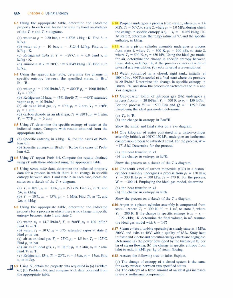
6.3 Using the appropriate table, determine the indicated
property. In each case, locate the state by hand on sketches
of the T–y and T–s diagrams.
(a) water at p 5 0.20 bar, s 5 4.3703 kJ/kg ? K. Find h, in
kJ/kg.
(b) water at p 5 10 bar, u 5 3124.4 kJ/kg. Find s, in
kJ/kg ? K.
(c) Refrigerant 134a at T 5 2288C, x 5 0.8. Find s, in
kJ/kg ? K.
(d) ammonia at T 5 208C, s 5 5.0849 kJ/kg ? K. Find u, in
kJ/kg.
6.4 Using the appropriate table, determine the change in
specific entropy between the specified states, in Btu/
lb ? 8R.
(a) water, p1 5 1000 lbf/in.2, T1 5 8008F, p2 5 1000 lbf/in.2,
T2 5 1008F.
(b) Refrigerant 134a, h1 5 47.91 Btu/lb, T1 5 2408F, saturated
vapor at p2 5 40 lbf/in.2
(c) air as an ideal gas, T1 5 408F, p1 5 2 atm, T2 5 4208F,
p2 5 1 atm.
(d) carbon dioxide as an ideal gas, T1 5 8208F, p1 5 1 atm,
T2 5 778F, p2 5 3 atm.
6.5 Using IT, determine the specific entropy of water at the
indicated states. Compare with results obtained from the
appropriate table.
(a) Specific entropy, in kJ/kg ? K, for the cases of Prob-
lem 6.1.
(b) Specific entropy, in Btu/lb ? 8R, for the cases of Prob-
lem 6.2.
6.6 Using IT, repeat Prob. 6.4. Compare the results obtained
using IT with those obtained using the appropriate table.
6.7 Using steam table data, determine the indicated property
data for a process in which there is no change in specific
entropy between state 1 and state 2. In each case, locate the
states on a sketch of the T–s diagram.
(a) T1 5 408C, x1 5 100%, p2 5 150 kPa. Find T2, in 8C, and
¢h, in kJ/kg.
(b) T1 5 108C, x1 5 75%, p2 5 1 MPa. Find T2, in 8C, and
¢u, in kJ/kg.
6.8 Using the appropriate table, determine the indicated
property for a process in which there is no change in specific
entropy between state 1 and state 2.
(a) water, p1 5 14.7 lbf/in.2, T1 5 5008F, p2 5 100 lbf/in.2
Find T2 in 8F.
(b) water, T1 5 108C, x1 5 0.75, saturated vapor at state 2.
Find p2 in bar.
(c) air as an ideal gas, T1 5 278C, p1 5 1.5 bar, T2 5 1278C.
Find p2 in bar.
(d) air as an ideal gas, T1 5 1008F, p1 5 3 atm, p2 5 2 atm.
Find T2 in 8F.
(e) Refrigerant 134a, T1 5 208C, p1 5 5 bar, p2 5 1 bar. Find
y2 in m3/kg.
6.9 Using IT, obtain the property data requested in (a) Prob lem
6.7, (b) Problem 6.8, and compare with data obtained from
the appropriate table.
6.10 Propane undergoes a process from state 1, where p1 5 1.4
MPa, T1 5 608C, to state 2, where p2 5 1.0 MPa, during which
the change in specific entropy is s2 2 s1 5 20.035 kJ/kg ? K.
At state 2, determine the temperature, in 8C, and the specific
enthalpy, in kJ/kg.
6.11 Air in a piston–cylinder assembly undergoes a process
from state 1, where T1 5 300 K, p1 5 100 kPa, to state 2,
where T2 5 500 K, p2 5 650 kPa. Using the ideal gas model
for air, determine the change in specific entropy between
these states, in kJ/kg ? K, if the process occurs (a) without
internal irreversibilities, (b) with internal irreversibilities.
6.12 Water contained in a closed, rigid tank, initially at
100 lbf/in.2, 8008F, is cooled to a final state where the pressure
is 20 lbf/in.2 Determine the change in specific entropy, in
Btu/lb ? 8R, and show the process on sketches of the T–y and
T–s diagrams.
6.13 One-quarter lbmol of nitrogen gas (N2) undergoes a
process from p1 5 20 lbf/in.2, T1 5 5008R to p2 5 150 lbf/in.2
For the process W 5 2500 Btu and Q 5 2125.9 Btu.
Employing the ideal gas model, determine
(a) T2, in 8R.
(b) the change in entropy, in Btu/8R.
Show the initial and final states on a T–s diagram.
6.14 One kilogram of water contained in a piston–cylinder
assembly, initially at 1608C, 150 kPa, undergoes an isothermal
compression process to saturated liquid. For the process, W 5
2471.5 kJ. Determine for the process,
(a) the heat transfer, in kJ.
(b) the change in entropy, in kJ/K.
Show the process on a sketch of the T–s diagram.
6.15 One-tenth kmol of carbon monoxide (CO) in a piston–
cylinder assembly undergoes a process from p1 5 150 kPa,
T1 5 300 K to p2 5 500 kPa, T2 5 370 K. For the process,
W 5 2300 kJ. Employing the ideal gas model, determine
(a) the heat transfer, in kJ.
(b) the change in entropy, in kJ/K.
Show the process on a sketch of the T–s diagram.
6.16 Argon in a piston–cylinder assembly is compressed from
state 1, where T1 5 300 K, V1 5 1 m3, to state 2, where
T2 5 200 K. If the change in specific entropy is s2 2 s1 5
20.27 kJ/kg ? K, determine the final volume, in m3. Assume
the ideal gas model with k 5 1.67.
6.17 Steam enters a turbine operating at steady state at 1 MPa,
2008C and exits at 408C with a quality of 83%. Stray heat
transfer and kinetic and potential energy effects are negligible.
Determine (a) the power developed by the turbine, in kJ per
kg of steam flowing, (b) the change in specific entropy from
inlet to exit, in kJ/K per kg of steam flowing.
6.18 Answer the following true or false. Explain.
(a) The change of entropy of a closed system is the same
for every process between two specified states.
(b) The entropy of a fixed amount of an ideal gas increases
in every isothermal compression.
c06UsingEntropy.indd Page 336 6/30/10 9:48:21 AM user-s146 c06UsingEntropy.indd Page 336 6/30/10 9:48:21 AM user-s146 /Users/user-s146/Desktop/Merry_X-Mas/New/Users/user-s146/Desktop/Merry_X-Mas/New

(c) The specific internal energy and enthalpy of an ideal gas
are each functions of temperature alone but its specific
entropy depends on two independent intensive properties.
(d) One of the T ds equations has the form T ds 5 du 2
p dy.(e) The entropy of a fixed amount of an incompressible
substance increases in every process in which temperature
decreases.
6.19 Showing all steps, derive Eqs. 6.43, 6.44, and 6.45.
Analyzing Internally Reversible Processes
6.20 One kilogram of water in a piston–cylinder assembly
undergoes the two internally reversible processes in series
shown in Fig. P6.20. For each process, determine, in kJ, the
heat transfer and the work.
6.23 One pound mass of water in a piston–cylinder assembly,
initially a saturated liquid at 1 atm, undergoes a constant-
pressure, internally reversible expansion to x 5 90%. Determine
the work and heat transfer, each in Btu. Sketch the process on
p–y and T–s coordinates. Associate the work and heat transfer
with areas on these diagrams.
6.24 A gas within a piston–cylinder assembly undergoes an
isothermal process at 400 K during which the change in
entropy is 20.3 kJ/K. Assuming the ideal gas model for the
gas and negligible kinetic and potential energy effects,
evaluate the work, in kJ.
6.25 Water within a piston–cylinder assembly, initially at
10 lbf/in.2, 5008F, undergoes an internally reversible process
to 80 lbf/in.2, 8008F, during which the temperature varies
linearly with specific entropy. For the water, determine the
work and heat transfer, each in Btu/lb. Neglect kinetic and
potential energy effects.
6.26 Nitrogen (N2) initially occupying 0.1 m3 at 6 bar, 2478C
undergoes an internally reversible expansion during which
pV1.20 5 constant to a final state where the temperature is
378C. Assuming the ideal gas model, determine
(a) the pressure at the final state, in bar.
(b) the work and heat transfer, each in kJ.
(c) the entropy change, in kJ/K.
6.27 Air in a piston–cylinder assembly and modeled as an ideal
gas undergoes two internally reversible processes in series
from state 1, where T1 5 290 K, p1 5 1 bar.
Process 1–2: Compression to p2 5 5 bar during which pV 1.19 5
constant.
Process 2–3: Isentropic expansion to p3 5 1 bar.
(a) Sketch the two processes in series on T–s coordinates.
(b) Determine the temperature at state 2, in K.
(c) Determine the net work, in kJ/kg.
6.28 One lb of oxygen, O2, in a piston–cylinder assembly undergoes
a cycle consisting of the following processes:
Process 1–2: Constant-pressure expansion from T1 5 4508R,
p1 5 30 lbf/in.2 to T2 5 11208R.
Process 2–3: Compression to T3 5 8008R and p3 5 53.3 lbf/in.2
with Q23 5 260 Btu.
Process 3–1: Constant-volume cooling to state 1.
Employing the ideal gas model with cp evaluated at T1,
determine the change in specific entropy, in Btu/lb ? 8R, for
each process. Sketch the cycle on p–y and T–s coordinates.
6.29 One-tenth kilogram of a gas in a piston–cylinder assembly
undergoes a Carnot power cycle for which the isothermal
expansion occurs at 800 K. The change in specific entropy
of the gas during the isothermal compression, which
occurs at 400 K, is 225 kJ/kg ? K. Determine (a) the net
work developed per cycle, in kJ, and (b) the thermal
efficiency.
6.21 One kilogram of water in a piston–cylinder assembly
undergoes the two internally reversible processes in series
shown in Fig. P6.21. For each process, determine, in kJ, the
heat transfer and the work.
T
s
1
23
p3 = 1.5 MPa
p1 = 0.1 MPa
T1 = 100°C
p2 = 0.5 MPa
T = constant
s = constant
Fig. P6.20
T
s
1
2
3
p3 = 1.0 MPa
T3 = 400°C
p1 = 0.1 MPa
T1 = 100°C
p = constant
s = constant
Fig. P6.21
6.22 One kilogram of water in a piston–cylinder assembly,
initially at 1608C, 1.5 bar, undergoes an isothermal, internally
reversible compression process to the saturated liquid state.
Determine the work and heat transfer, each in kJ. Sketch the
process on p–y and T–s coordinates. Associate the work and
heat transfer with areas on these diagrams.
Problems: Developing Engineering Skills 337
c06UsingEntropy.indd Page 337 10/11/10 6:10:42 PM f-392 c06UsingEntropy.indd Page 337 10/11/10 6:10:42 PM f-392 /Users/f-392/Desktop/Nalini 23.9/ch05/Users/f-392/Desktop/Nalini 23.9/ch05

338 Chapter 6 Using Entropy
6.30 Figure P6.30 provides the T–s diagram of a Carnot
refrigeration cycle for which the substance is Refrigerant
134a. Determine the coefficient of performance.
6.33 Water in a piston–cylinder assembly undergoes a Carnot
power cycle. At the beginning of the isothermal expansion, the
temperature is 2508C and the quality is 80%. The isothermal
expansion continues until the pressure is 2 MPa. The adiabatic
expansion then occurs to a final temperature of 1758C.
(a) Sketch the cycle on T–s coordinates.
(b) Determine the heat transfer and work, in kJ/kg, for each
process.
(c) Evaluate the thermal efficiency.
6.34 A Carnot power cycle operates at steady state as shown
in Fig. 5.15 with water as the working fluid. The boiler
pressure is 200 lbf/in.2, with saturated liquid entering and
saturated vapor exiting. The condenser pressure is 20 lbf/in.2
(a) Sketch the cycle on T–s coordinates.
(b) Determine the heat transfer and work for each process,
in Btu per lb of water flowing.
(c) Evaluate the thermal efficiency.
6.35 Figure P6.35 shows a Carnot heat pump cycle operating at
steady state with ammonia as the working fluid. The condenser
temperature is 1208F, with saturated vapor entering and
saturated liquid exiting. The evaporator temperature is 108F.
(a) Determine the heat transfer and work for each process,
in Btu per lb of ammonia flowing.
(b) Evaluate the coefficient of performance for the heat
pump.
(c) Evaluate the coefficient of performance for a Carnot
refrigeration cycle operating as shown in the figure.
Applying the Entropy Balance: Closed Systems
6.36 A closed system undergoes a process in which work is done
on the system and the heat transfer Q occurs only at temperature
Tb. For each case, determine whether the entropy change of
the system is positive, negative, zero, or indeterminate.
(a) internally reversible process, Q . 0.
(b) internally reversible process, Q 5 0.
(c) internally reversible process, Q , 0.
(d) internal irreversibilities present, Q . 0.
(e) internal irreversibilities present, Q 5 0.
(f) internal irreversibilities present, Q , 0.
6.37 Answer the following true or false. Explain.
(a) A process that violates the second law of thermodynamics
violates the first law of thermodynamics.
(b) When a net amount of work is done on a closed system
undergoing an internally reversible process, a net heat
transfer of energy from the system also occurs.
(c) One corollary of the second law of thermodynamics
states that the change in entropy of a closed system must be
greater than zero or equal to zero.
(d) A closed system can experience an increase in entropy
only when irreversibilities are present within the system
during the process.
(e) Entropy is produced in every internally reversible
process of a closed system.
(f) In an adiabatic and internally reversible process of a
closed system, the entropy remains constant.
(g) The energy of an isolated system must remain constant,
but the entropy can only decrease.
T (°C)
0
s (kJ/kg·K)
p3 = 16 bar
3
21
4
Fig. P6.30
6.31 Figure P6.31 provides the T–s diagram of a Carnot heat
pump cycle for which the substance is ammonia. Determine
the net work input required, in kJ, for 50 cycles of operation
and 0.1 kg of substance.
T
s
20 bar
1 bar
1
4 3
2
x3 = 90%
Fig. P6.31
6.32 Air in a piston–cylinder assembly undergoes a Carnot
power cycle. The isothermal expansion and compression
processes occur at 1400 K and 350 K, respectively. The
pressures at the beginning and end of the isothermal
compression are 100 kPa and 500 kPa, respectively. Assuming
the ideal gas model with cp 5 1.005 kJ/kg ? K, determine
(a) the pressures at the beginning and end of the isothermal
expansion, each in kPa.
(b) the heat transfer and work, in kJ/kg, for each process.
(c) the thermal efficiency.
c06UsingEntropy.indd Page 338 5/26/10 3:29:32 PM user-s146 c06UsingEntropy.indd Page 338 5/26/10 3:29:32 PM user-s146 /Users/user-s146/Desktop/Merry_X-Mas/New/Users/user-s146/Desktop/Merry_X-Mas/New

6.38 One lb of water contained in a piston–cylinder assembly,
initially saturated vapor at 1 atm, is condensed at constant
pressure to saturated liquid. Evaluate the heat transfer, in
Btu, and the entropy production, in Btu/8R, for
(a) the water as the system.
(b) an enlarged system consisting of the water and enough
of the nearby surroundings that heat transfer occurs only at
the ambient temperature, 808F.
Assume the state of the nearby surroundings does not change
during the process of the water, and ignore kinetic and
potential energy.
6.39 Five kg of water contained in a piston–cylinder assembly
expand from an initial state where T1 5 4008C, p1 5 700 kPa
to a final state where T2 5 2008C, p2 5 300 kPa, with no
significant effects of kinetic and potential energy. The
accompanying table provides additional data at the two
states. It is claimed that the water undergoes an adiabatic
process between these states, while developing work. Evaluate
this claim.
pressure, in bar, and (c) the amount of entropy produced, in
kJ/K. Ignore kinetic and potential energy.
6.42 Air contained in a rigid, insulated tank fitted with a
paddle wheel, initially at 4 bar, 408C and a volume of 0.2 m3,
is stirred until its temperature is 3538C. Assuming the ideal
gas model with k 5 1.4 for the air, determine (a) the final
pressure, in bar, (b) the work, in kJ, and (c) the amount of
entropy produced, in kJ/K. Ignore kinetic and potential
energy.
6.43 Air contained in a rigid, insulated tank fitted with a
paddle wheel, initially at 300 K, 2 bar, and a volume of 2 m3,
is stirred until its temperature is 500 K. Assuming the ideal
gas model for the air, and ignoring kinetic and potential
energy, determine (a) the final pressure, in bar, (b) the work,
in kJ, and (c) the amount of entropy produced, in kJ/K. Solve
using
(a) data from Table A-22.
(b) constant cy read from Table A-20 at 400 K.
Compare the results of parts (a) and (b).
6.44 A rigid, insulated container fitted with a paddle wheel
contains 5 lb of water, initially at 2608F and a quality of 60%.
The water is stirred until the temperature is 3508F. For the
water, determine (a) the work, in Btu, and (b) the amount
of entropy produced, in Btu/8R.
6.45 Two kilograms of air contained in a piston–cylinder
assembly are initially at 1.5 bar and 400 K. Can a final state
at 6 bar and 500 K be attained in an adiabatic process?
6.46 One pound mass of Refrigerant 134a contained within a
piston–cylinder assembly undergoes a process from a state
where the temperature is 608F and the refrigerant is saturated
liquid to a state where the pressure is 140 lbf/in.2 and quality
is 50%. Determine the change in specific entropy of the
refrigerant, in Btu/lb ? 8R. Can this process be accomplished
adiabatically?
2
Condenser
Evaporator
Compressor
Qout
·
Qin
·
Wc
·
3
4 1
Turbine
120°F
10°F
Cold region
Warm region
Wt
·T
s
4 1
3 2
Fig. P6.35
State T(8C) p(kPa) y(m3/kg) u(kJ/kg) h(kJ/kg) s(kJ/kg ? K)
1 400 700 0.4397 2960.9 3268.7 7.6350 2 200 300 0.7160 2650.7 2865.5 7.3115
6.40 Two m3 of air in a rigid, insulated container fitted with a
paddle wheel is initially at 293 K, 200 kPa. The air receives
710 kJ by work from the paddle wheel. Assuming the ideal
gas model with cy 5 0.72 kJ/kg ? K, determine for the air
(a) the mass, in kg, (b) final temperature, in K, and (c) the
amount of entropy produced, in kJ/K.
6.41 Air contained in a rigid, insulated tank fitted with a
paddle wheel, initially at 1 bar, 330 K and a volume of 1.93 m3,
receives an energy transfer by work from the paddle wheel
in an amount of 400 kJ. Assuming the ideal gas model for
the air, determine (a) the final temperature, in K, (b) the final
Problems: Developing Engineering Skills 339
c06UsingEntropy.indd Page 339 10/12/10 2:59:11 PM f-392 c06UsingEntropy.indd Page 339 10/12/10 2:59:11 PM f-392 /Users/f-392/Desktop/Nalini 23.9/ch05/Users/f-392/Desktop/Nalini 23.9/ch05
340 Chapter 6 Using Entropy
6.47 Refrigerant 134a contained in a piston–cylinder assembly
rapidly expands from an initial state where T1 5 1408F, p1 5
200 lbf/in.2 to a final state where p2 5 5 lbf/in.2 and the
quality, x2, is (a) 99%, (b) 95%. In each case, determine if
the process can occur adiabatically. If yes, determine the
work, in Btu/lb, for an adiabatic expansion between these
states. If no, determine the direction of the heat transfer.
6.48 One kg of air contained in a piston–cylinder assembly
undergoes a process from an initial state where T1 5 300 K,
y1 5 0.8 m3/kg to a final state where T2 5 420 K, y2 5
0.2 m3/kg. Can this process occur adiabatically? If yes,
determine the work, in kJ, for an adiabatic process between
these states. If no, determine the direction of the heat
transfer. Assume the ideal gas model for air.
6.49 Air as an ideal gas contained within a piston–cylinder
assembly is compressed between two specified states. In each
of the following cases, can the process occur adiabatically? If
yes, determine the work in appropriate units for an adiabatic
process between these states. If no, determine the direction
of the heat transfer.
(a) State 1: p1 5 0.1 MPa, T1 5 278C. State 2: p2 5 0.5 MPa,
T2 5 2078C. Use Table A-22 data.
(b) State 1: p1 5 3 atm, T1 5 808F State 2: p2 5 10 atm,
T2 5 2408F. Assume cp 5 0.241 Btu/lb8R.
6.50 One kilogram of propane initially at 8 bar and 508C
undergoes a process to 3 bar, 208C while being rapidly
expanded in a piston–cylinder assembly. Heat transfer between
the propane and its surroundings occurs at an average
temperature of 358C. The work done by the propane is
measured as 42.4 kJ. Kinetic and potential energy effects can
be ignored. Determine whether it is possible for the work
measurement to be correct.
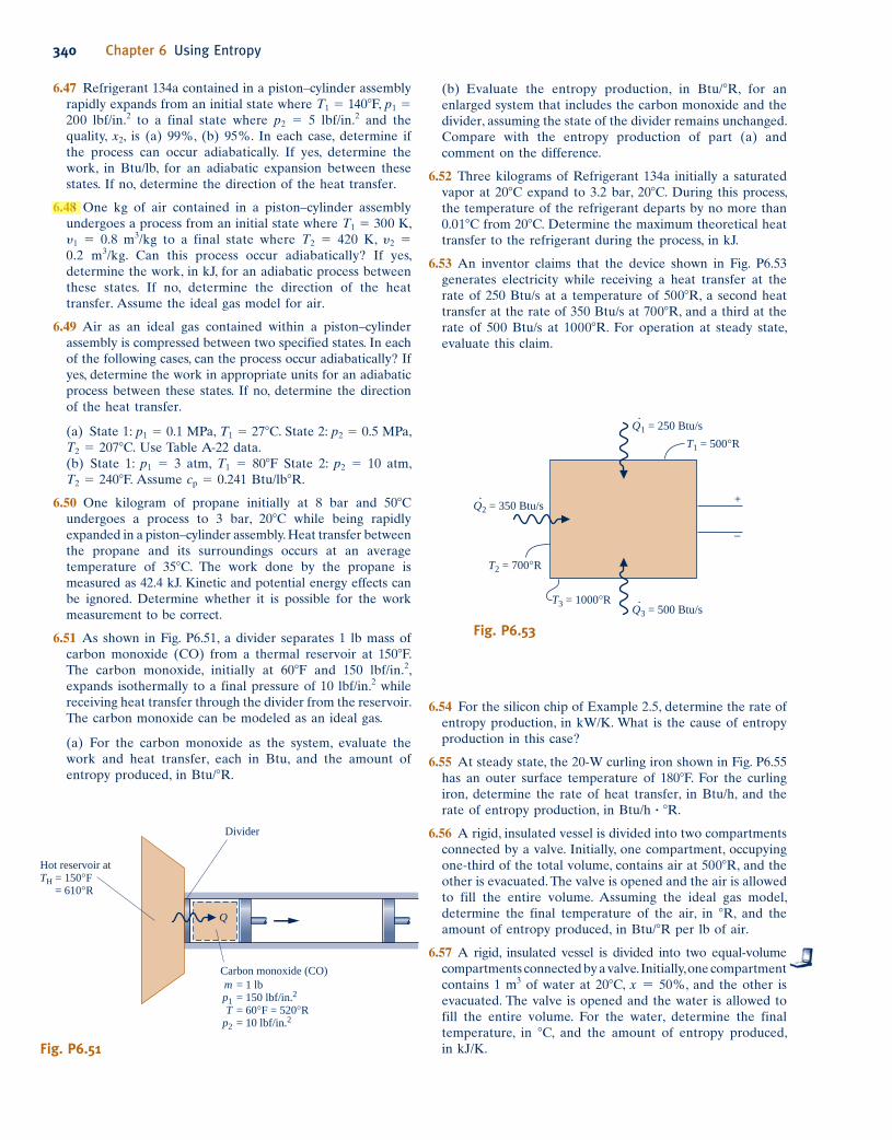
6.51 As shown in Fig. P6.51, a divider separates 1 lb mass of
carbon monoxide (CO) from a thermal reservoir at 1508F.
The carbon monoxide, initially at 608F and 150 lbf/in.2,
expands isothermally to a final pressure of 10 lbf/in.2 while
receiving heat transfer through the divider from the reservoir.
The carbon monoxide can be modeled as an ideal gas.
(a) For the carbon monoxide as the system, evaluate the
work and heat transfer, each in Btu, and the amount of
entropy produced, in Btu/8R.
(b) Evaluate the entropy production, in Btu/8R, for an
enlarged system that includes the carbon monoxide and the
divider, assuming the state of the divider remains unchanged.
Compare with the entropy production of part (a) and
comment on the difference.
6.52 Three kilograms of Refrigerant 134a initially a saturated
vapor at 208C expand to 3.2 bar, 208C. During this process,
the temperature of the refrigerant departs by no more than
0.018C from 208C. Determine the maximum theoretical heat
transfer to the refrigerant during the process, in kJ.
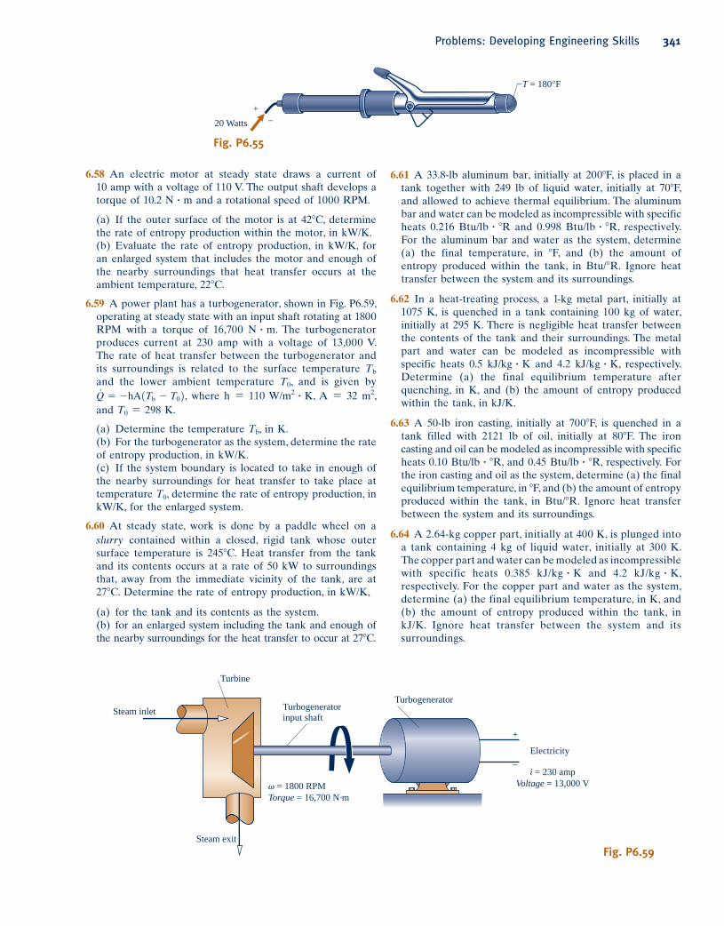
6.53 An inventor claims that the device shown in Fig. P6.53
generates electricity while receiving a heat transfer at the
rate of 250 Btu/s at a temperature of 5008R, a second heat
transfer at the rate of 350 Btu/s at 7008R, and a third at the
rate of 500 Btu/s at 10008R. For operation at steady state,
evaluate this claim.
6.54 For the silicon chip of Example 2.5, determine the rate of
entropy production, in kW/K. What is the cause of entropy
production in this case?
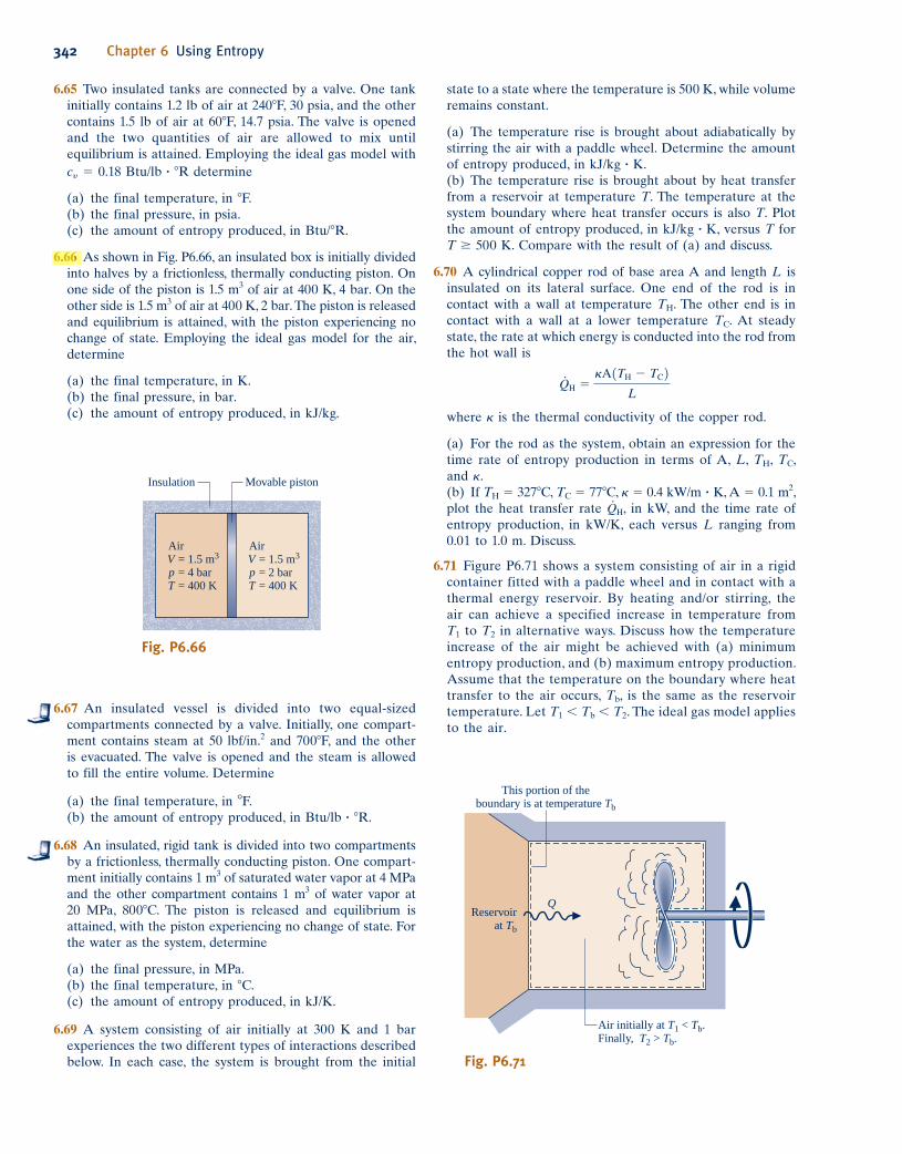
6.55 At steady state, the 20-W curling iron shown in Fig. P6.55
has an outer surface temperature of 1808F. For the curling
iron, determine the rate of heat transfer, in Btu/h, and the
rate of entropy production, in Btu/h ? 8R.
6.56 A rigid, insulated vessel is divided into two compartments
connected by a valve. Initially, one compartment, occupying
one-third of the total volume, contains air at 5008R, and the
other is evacuated. The valve is opened and the air is allowed
to fill the entire volume. Assuming the ideal gas model,
determine the final temperature of the air, in 8R, and the
amount of entropy produced, in Btu/8R per lb of air.
6.57 A rigid, insulated vessel is divided into two equal-volume
compartments connected by a valve. Initially, one compartment
contains 1 m3 of water at 208C, x 5 50%, and the other is
evacuated. The valve is opened and the water is allowed to
fill the entire volume. For the water, determine the final
temperature, in 8C, and the amount of entropy produced,
in kJ/K.
Q
Hot reservoir at
TH = 150°F
= 610°R
Divider
Carbon monoxide (CO)
= 1 lb
= 150 lbf/in.2
= 60°F = 520°R
= 10 lbf/in.2
mp1
Tp2
Fig. P6.51
Q·1 = 250 Btu/s
Q·2 = 350 Btu/s
Q·3 = 500 Btu/s
T1 = 500°R
+
T2 = 700°R
T3 = 1000°R
–
Fig. P6.53
c06UsingEntropy.indd Page 340 6/30/10 9:48:23 AM user-s146 c06UsingEntropy.indd Page 340 6/30/10 9:48:23 AM user-s146 /Users/user-s146/Desktop/Merry_X-Mas/New/Users/user-s146/Desktop/Merry_X-Mas/New
6.61 A 33.8-lb aluminum bar, initially at 2008F, is placed in a
tank together with 249 lb of liquid water, initially at 708F,
and allowed to achieve thermal equilibrium. The aluminum
bar and water can be modeled as incompressible with specific
heats 0.216 Btu/lb ? 8R and 0.998 Btu/lb ? 8R, respectively.
For the aluminum bar and water as the system, determine
(a) the final temperature, in 8F, and (b) the amount of
entropy produced within the tank, in Btu/8R. Ignore heat
transfer between the system and its surroundings.
6.62 In a heat-treating process, a 1-kg metal part, initially at
1075 K, is quenched in a tank containing 100 kg of water,
initially at 295 K. There is negligible heat transfer between
the contents of the tank and their surroundings. The metal
part and water can be modeled as incompressible with
specific heats 0.5 kJ/kg ? K and 4.2 kJ/kg ? K, respectively.
Determine (a) the final equilibrium temperature after
quenching, in K, and (b) the amount of entropy produced
within the tank, in kJ/K.
6.63 A 50-lb iron casting, initially at 7008F, is quenched in a
tank filled with 2121 lb of oil, initially at 808F. The iron
casting and oil can be modeled as incompressible with specific
heats 0.10 Btu/lb ? 8R, and 0.45 Btu/lb ? 8R, respectively. For
the iron casting and oil as the system, determine (a) the final
equilibrium temperature, in 8F, and (b) the amount of entropy
produced within the tank, in Btu/8R. Ignore heat transfer
between the system and its surroundings.
6.64 A 2.64-kg copper part, initially at 400 K, is plunged into
a tank containing 4 kg of liquid water, initially at 300 K.
The copper part and water can be modeled as incompressible
with specific heats 0.385 kJ/kg ? K and 4.2 kJ/kg ? K,
respectively. For the copper part and water as the system,
determine (a) the final equilibrium temperature, in K, and
(b) the amount of entropy produced within the tank, in
kJ/K. Ignore heat transfer between the system and its
surroundings.
6.58 An electric motor at steady state draws a current of
10 amp with a voltage of 110 V. The output shaft develops a
torque of 10.2 N ? m and a rotational speed of 1000 RPM.
(a) If the outer surface of the motor is at 428C, determine
the rate of entropy production within the motor, in kW/K.
(b) Evaluate the rate of entropy production, in kW/K, for
an enlarged system that includes the motor and enough of
the nearby surroundings that heat transfer occurs at the
ambient temperature, 228C.
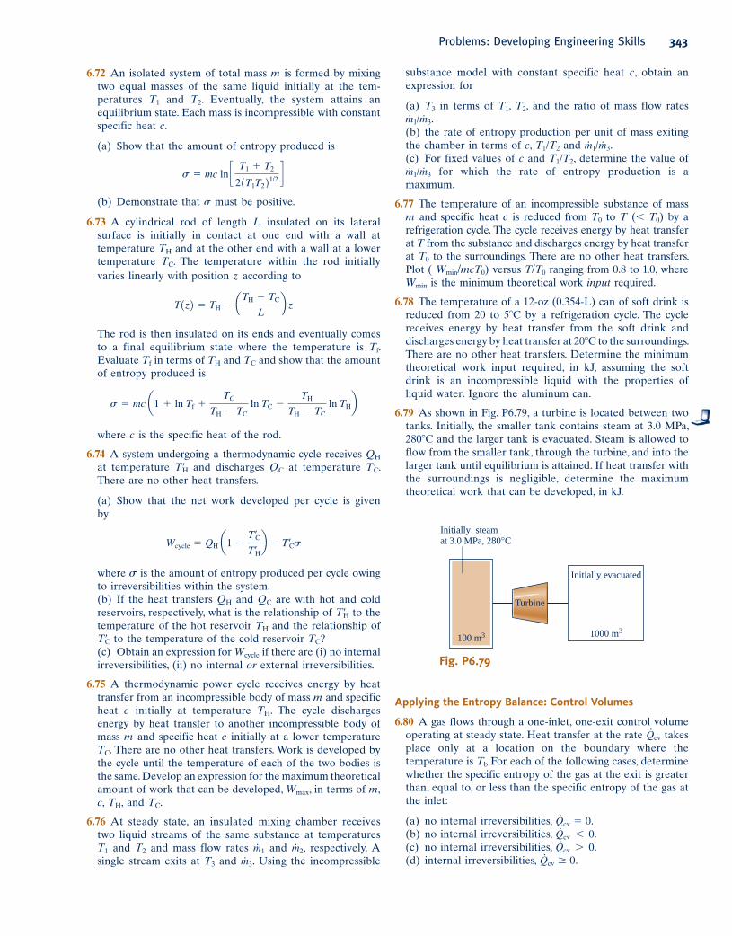
6.59 A power plant has a turbogenerator, shown in Fig. P6.59,
operating at steady state with an input shaft rotating at 1800
RPM with a torque of 16,700 N ? m. The turbogenerator
produces current at 230 amp with a voltage of 13,000 V.
The rate of heat transfer between the turbogenerator and
its surroundings is related to the surface temperature Tb
and the lower ambient temperature T0, and is given by
Q#
5 2hA1Tb 2 T02, where h 5 110 W/m2 ? K, A 5 32 m2,
and T0 5 298 K.
(a) Determine the temperature Tb, in K.
(b) For the turbogenerator as the system, determine the rate
of entropy production, in kW/K.
(c) If the system boundary is located to take in enough of
the nearby surroundings for heat transfer to take place at
temperature T0, determine the rate of entropy production, in
kW/K, for the enlarged system.
6.60 At steady state, work is done by a paddle wheel on a
slurry contained within a closed, rigid tank whose outer
surface temperature is 2458C. Heat transfer from the tank
and its contents occurs at a rate of 50 kW to surroundings
that, away from the immediate vicinity of the tank, are at
278C. Determine the rate of entropy production, in kW/K,
(a) for the tank and its contents as the system.
(b) for an enlarged system including the tank and enough of
the nearby surroundings for the heat transfer to occur at 278C.
T = 180°F
20 Watts
+
–
Fig. P6.55
Turbine
Steam inlet
Steam exit
Electricity
TurbogeneratorTurbogenerator
input shaft
i = 230 amp
Voltage = 13,000 V� = 1800 RPM
Torque = 16,700 N·m
–
+
Fig. P6.59
Problems: Developing Engineering Skills 341
c06UsingEntropy.indd Page 341 5/26/10 3:29:43 PM user-s146 c06UsingEntropy.indd Page 341 5/26/10 3:29:43 PM user-s146 /Users/user-s146/Desktop/Merry_X-Mas/New/Users/user-s146/Desktop/Merry_X-Mas/New
342 Chapter 6 Using Entropy
state to a state where the temperature is 500 K, while volume
remains constant.
(a) The temperature rise is brought about adiabatically by
stirring the air with a paddle wheel. Determine the amount
of entropy produced, in kJ/kg ? K.
(b) The temperature rise is brought about by heat transfer
from a reservoir at temperature T. The temperature at the
system boundary where heat transfer occurs is also T. Plot
the amount of entropy produced, in kJ/kg ? K, versus T for
T $ 500 K. Compare with the result of (a) and discuss.
6.70 A cylindrical copper rod of base area A and length L is
insulated on its lateral surface. One end of the rod is in
contact with a wall at temperature TH. The other end is in
contact with a wall at a lower temperature TC. At steady
state, the rate at which energy is conducted into the rod from
the hot wall is
Q#
H 5kA1TH 2 TC2
L
where k is the thermal conductivity of the copper rod.
(a) For the rod as the system, obtain an expression for the
time rate of entropy production in terms of A, L, TH, TC,
and k.
(b) If TH 5 3278C, TC 5 778C, k 5 0.4 kW/m ? K, A 5 0.1 m2,
plot the heat transfer rate Q#
H, in kW, and the time rate of
entropy production, in kW/K, each versus L ranging from
0.01 to 1.0 m. Discuss.
6.71 Figure P6.71 shows a system consisting of air in a rigid
container fitted with a paddle wheel and in contact with a
thermal energy reservoir. By heating and/or stirring, the
air can achieve a specified increase in temperature from
T1 to T2 in alternative ways. Discuss how the temperature
increase of the air might be achieved with (a) minimum
entropy production, and (b) maximum entropy production.
Assume that the temperature on the boundary where heat
transfer to the air occurs, Tb, is the same as the reservoir
temperature. Let T1 , Tb , T2. The ideal gas model applies
to the air.
6.65 Two insulated tanks are connected by a valve. One tank
initially contains 1.2 lb of air at 2408F, 30 psia, and the other
contains 1.5 lb of air at 608F, 14.7 psia. The valve is opened
and the two quantities of air are allowed to mix until
equilibrium is attained. Employing the ideal gas model with
cy 5 0.18 Btu/lb ? 8R determine
(a) the final temperature, in 8F.
(b) the final pressure, in psia.
(c) the amount of entropy produced, in Btu/8R.
6.66 As shown in Fig. P6.66, an insulated box is initially divided
into halves by a frictionless, thermally conducting piston. On
one side of the piston is 1.5 m3 of air at 400 K, 4 bar. On the
other side is 1.5 m3 of air at 400 K, 2 bar. The piston is released
and equilibrium is attained, with the piston experiencing no
change of state. Employing the ideal gas model for the air,
determine
(a) the final temperature, in K.
(b) the final pressure, in bar.
(c) the amount of entropy produced, in kJ/kg.
Insulation Movable piston
Air
= 1.5 m3
= 4 bar
= 400 K
VpT
Air
= 1.5 m3
= 2 bar
= 400 K
VpT
Fig. P6.66
6.67 An insulated vessel is divided into two equal-sized
compartments connected by a valve. Initially, one compart-
ment contains steam at 50 lbf/in.2 and 7008F, and the other
is evacuated. The valve is opened and the steam is allowed
to fill the entire volume. Determine
(a) the final temperature, in 8F.
(b) the amount of entropy produced, in Btu/lb ? 8R.
6.68 An insulated, rigid tank is divided into two compartments
by a frictionless, thermally conducting piston. One compart-
ment initially contains 1 m3 of saturated water vapor at 4 MPa
and the other compartment contains 1 m3 of water vapor at
20 MPa, 8008C. The piston is released and equilibrium is
attained, with the piston experiencing no change of state. For
the water as the system, determine
(a) the final pressure, in MPa.
(b) the final temperature, in 8C.
(c) the amount of entropy produced, in kJ/K.
6.69 A system consisting of air initially at 300 K and 1 bar
experiences the two different types of interactions described
below. In each case, the system is brought from the initial
Reservoir
at Tb
Q
This portion of the
boundary is at temperature Tb
Air initially at T1 < Tb.
Finally, T2 > Tb.
Fig. P6.71
c06UsingEntropy.indd Page 342 6/30/10 9:48:23 AM user-s146 c06UsingEntropy.indd Page 342 6/30/10 9:48:23 AM user-s146 /Users/user-s146/Desktop/Merry_X-Mas/New/Users/user-s146/Desktop/Merry_X-Mas/New
substance model with constant specific heat c, obtain an
expression for
(a) T3 in terms of T1, T2, and the ratio of mass flow rates
m#
1/m# 3.
(b) the rate of entropy production per unit of mass exiting
the chamber in terms of c, T1/T2 and m#
1/m# 3.
(c) For fixed values of c and T1/T2, determine the value of
m#
1/m# 3 for which the rate of entropy production is a
maximum.
6.77 The temperature of an incompressible substance of mass
m and specific heat c is reduced from T0 to T (, T0) by a
refrigeration cycle. The cycle receives energy by heat transfer
at T from the substance and discharges energy by heat transfer
at T0 to the surroundings. There are no other heat transfers.
Plot ( Wmin/mcT0) versus T/T0 ranging from 0.8 to 1.0, where
Wmin is the minimum theoretical work input required.
6.78 The temperature of a 12-oz (0.354-L) can of soft drink is
reduced from 20 to 58C by a refrigeration cycle. The cycle
receives energy by heat transfer from the soft drink and
discharges energy by heat transfer at 208C to the surroundings.
There are no other heat transfers. Determine the minimum
theoretical work input required, in kJ, assuming the soft
drink is an incompressible liquid with the properties of
liquid water. Ignore the aluminum can.
6.79 As shown in Fig. P6.79, a turbine is located between two
tanks. Initially, the smaller tank contains steam at 3.0 MPa,
2808C and the larger tank is evacuated. Steam is allowed to
flow from the smaller tank, through the turbine, and into the
larger tank until equilibrium is attained. If heat transfer with
the surroundings is negligible, determine the maximum
theoretical work that can be developed, in kJ.
6.72 An isolated system of total mass m is formed by mixing
two equal masses of the same liquid initially at the tem-
peratures T1 and T2. Eventually, the system attains an
equilibrium state. Each mass is incompressible with constant
specific heat c.
(a) Show that the amount of entropy produced is
s 5 mc ln c T1 1 T2
21T1T221/2 d(b) Demonstrate that s must be positive.
6.73 A cylindrical rod of length L insulated on its lateral
surface is initially in contact at one end with a wall at
temperature TH and at the other end with a wall at a lower
temperature TC. The temperature within the rod initially
varies linearly with position z according to
T1z2 5 TH 2 aTH 2 TC
Lb z
The rod is then insulated on its ends and eventually comes
to a final equilibrium state where the temperature is Tf.
Evaluate Tf in terms of TH and TC and show that the amount
of entropy produced is
s 5 mc a1 1 ln Tf 1TC
TH 2 TC ln TC 2
TH
TH 2 TC ln THb
where c is the specific heat of the rod.
6.74 A system undergoing a thermodynamic cycle receives QH
at temperature T9H and discharges QC at temperature T9C.
There are no other heat transfers.
(a) Show that the net work developed per cycle is given
by
Wcycle 5 QH a1 2T¿C
T¿Hb 2 T¿Cs
where s is the amount of entropy produced per cycle owing
to irreversibilities within the system.
(b) If the heat transfers QH and QC are with hot and cold
reservoirs, respectively, what is the relationship of T9H to the
temperature of the hot reservoir TH and the relationship of
T9C to the temperature of the cold reservoir TC?
(c) Obtain an expression for Wcycle if there are (i) no internal
irreversibilities, (ii) no internal or external irreversibilities.
6.75 A thermodynamic power cycle receives energy by heat
transfer from an incompressible body of mass m and specific
heat c initially at temperature TH. The cycle discharges
energy by heat transfer to another incompressible body of
mass m and specific heat c initially at a lower temperature
TC. There are no other heat transfers. Work is developed by
the cycle until the temperature of each of the two bodies is
the same. Develop an expression for the maximum theoretical
amount of work that can be developed, Wmax, in terms of m, c, TH, and TC.
6.76 At steady state, an insulated mixing chamber receives
two liquid streams of the same substance at temperatures
T1 and T2 and mass flow rates m#
1 and m#
2, respectively. A
single stream exits at T3 and m#
3. Using the incompressible
Turbine
Initially: steam
at 3.0 MPa, 280°C
100 m3 1000 m3
Initially evacuated
Fig. P6.79
Applying the Entropy Balance: Control Volumes
6.80 A gas flows through a one-inlet, one-exit control volume
operating at steady state. Heat transfer at the rate Q#
cv takes
place only at a location on the boundary where the
temperature is Tb For each of the following cases, determine
whether the specific entropy of the gas at the exit is greater
than, equal to, or less than the specific entropy of the gas at
the inlet:
(a) no internal irreversibilities, Q#
cv 5 0.
(b) no internal irreversibilities, Q#
cv , 0.
(c) no internal irreversibilities, Q#
cv . 0.
(d) internal irreversibilities, Q#
cv $ 0.
Problems: Developing Engineering Skills 343
c06UsingEntropy.indd Page 343 6/30/10 9:48:24 AM user-s146 c06UsingEntropy.indd Page 343 6/30/10 9:48:24 AM user-s146 /Users/user-s146/Desktop/Merry_X-Mas/New/Users/user-s146/Desktop/Merry_X-Mas/New
344 Chapter 6 Using Entropy
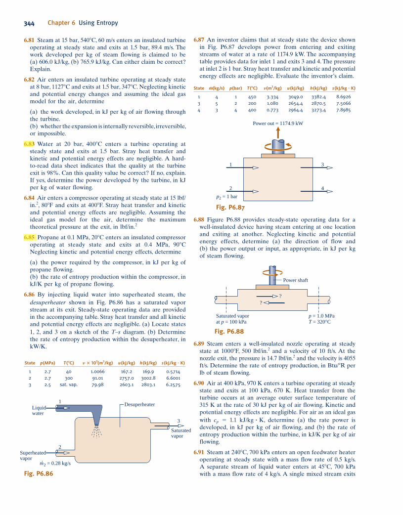
6.87 An inventor claims that at steady state the device shown
in Fig. P6.87 develops power from entering and exiting
streams of water at a rate of 1174.9 kW. The accompanying
table provides data for inlet 1 and exits 3 and 4. The pressure
at inlet 2 is 1 bar. Stray heat transfer and kinetic and potential
energy effects are negligible. Evaluate the inventor’s claim.
6.81 Steam at 15 bar, 5408C, 60 m/s enters an insulated turbine
operating at steady state and exits at 1.5 bar, 89.4 m/s. The
work developed per kg of steam flowing is claimed to be
(a) 606.0 kJ/kg, (b) 765.9 kJ/kg. Can either claim be correct?
Explain.
6.82 Air enters an insulated turbine operating at steady state
at 8 bar, 11278C and exits at 1.5 bar, 3478C. Neglecting kinetic
and potential energy changes and assuming the ideal gas
model for the air, determine
(a) the work developed, in kJ per kg of air flowing through
the turbine.
(b) whether the expansion is internally reversible, irreversible,
or impossible.
6.83 Water at 20 bar, 4008C enters a turbine operating at
steady state and exits at 1.5 bar. Stray heat transfer and
kinetic and potential energy effects are negligible. A hard-
to-read data sheet indicates that the quality at the turbine
exit is 98%. Can this quality value be correct? If no, explain.
If yes, determine the power developed by the turbine, in kJ
per kg of water flowing.
6.84 Air enters a compressor operating at steady state at 15 lbf/
in.2, 808F and exits at 4008F. Stray heat transfer and kinetic
and potential energy effects are negligible. Assuming the
ideal gas model for the air, determine the maximum
theoretical pressure at the exit, in lbf/in.2
6.85 Propane at 0.1 MPa, 208C enters an insulated compressor
operating at steady state and exits at 0.4 MPa, 908C
Neglecting kinetic and potential energy effects, determine
(a) the power required by the compressor, in kJ per kg of
propane flowing.
(b) the rate of entropy production within the compressor, in
kJ/K per kg of propane flowing.
6.86 By injecting liquid water into superheated steam, the
desuperheater shown in Fig. P6.86 has a saturated vapor
stream at its exit. Steady-state operating data are provided
in the accompanying table. Stray heat transfer and all kinetic
and potential energy effects are negligible. (a) Locate states
1, 2, and 3 on a sketch of the T–s diagram. (b) Determine
the rate of entropy production within the desuperheater, in
kW/K.
State p(MPa) T(8C) y 3 103(m3/kg) u(kJ/kg) h(kJ/kg) s(kJ/kg ? K)
1 2.7 40 1.0066 167.2 169.9 0.5714 2 2.7 300 91.01 2757.0 3002.8 6.6001 3 2.5 sat. vap. 79.98 2603.1 2803.1 6.2575
Superheatedvapor
Saturatedvapor
Desuperheater
2
1
Liquidwater
3
m· 2 = 0.28 kg/s
Fig. P6.86
p2 = 1 bar
Power out = 1174.9 kW
1
2
3
4
Fig. P6.87
State m#
(kg/s) p(bar) T(8C) y(m3/kg) u(kJ/kg) h(kJ/kg) s(kJ/kg ? K)
1 4 1 450 3.334 3049.0 3382.4 8.6926 3 5 2 200 1.080 2654.4 2870.5 7.5066 4 3 4 400 0.773 2964.4 3273.4 7.8985
6.88 Figure P6.88 provides steady-state operating data for a
well-insulated device having steam entering at one location
and exiting at another. Neglecting kinetic and potential
energy effects, determine (a) the direction of flow and
(b) the power output or input, as appropriate, in kJ per kg
of steam flowing.
Saturated vapor
at p = 100 kPa
p = 1.0 MPa
T = 320°C
Power shaft
?
?
Fig. P6.88
6.89 Steam enters a well-insulated nozzle operating at steady
state at 10008F, 500 lbf/in.2 and a velocity of 10 ft/s. At the
nozzle exit, the pressure is 14.7 lbf/in.2 and the velocity is 4055
ft/s. Determine the rate of entropy production, in Btu/8R per
lb of steam flowing.
6.90 Air at 400 kPa, 970 K enters a turbine operating at steady
state and exits at 100 kPa, 670 K. Heat transfer from the
turbine occurs at an average outer surface temperature of
315 K at the rate of 30 kJ per kg of air flowing. Kinetic and
potential energy effects are negligible. For air as an ideal gas
with cp 5 1.1 kJ/kg ? K, determine (a) the rate power is
developed, in kJ per kg of air flowing, and (b) the rate of
entropy production within the turbine, in kJ/K per kg of air
flowing.
6.91 Steam at 2408C, 700 kPa enters an open feedwater heater
operating at steady state with a mass flow rate of 0.5 kg/s.
A separate stream of liquid water enters at 458C, 700 kPa
with a mass flow rate of 4 kg/s. A single mixed stream exits
c06UsingEntropy.indd Page 344 5/28/10 1:23:04 PM user-s146 c06UsingEntropy.indd Page 344 5/28/10 1:23:04 PM user-s146 /Users/user-s146/Desktop/Merry_X-Mas/New/Users/user-s146/Desktop/Merry_X-Mas/New
at 700 kPa and temperature T. Stray heat transfer and kinetic
and potential energy effects can be ignored. Determine (a) T,
in 8C, and (b) the rate of entropy production within the
feedwater heater, in kW/K. (c) Locate the three principal
states on a sketch of the T–s diagram.
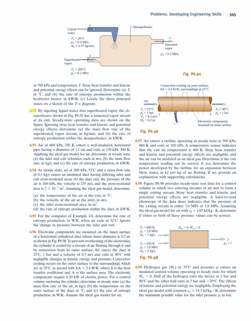
6.92 By injecting liquid water into superheated vapor, the de-superheater shown in Fig. P6.92 has a saturated vapor stream
at its exit. Steady-state operating data are shown on the
figure. Ignoring stray heat transfer and kinetic and potential
energy effects, determine (a) the mass flow rate of the
superheated vapor stream, in kg/min, and (b) the rate of
entropy production within the desuperheater, in kW/K.
6.93 Air at 600 kPa, 330 K enters a well-insulated, horizontal
pipe having a diameter of 1.2 cm and exits at 120 kPa, 300 K.
Applying the ideal gas model for air, determine at steady state
(a) the inlet and exit velocities, each in m/s, (b) the mass flow
rate, in kg/s, and (c) the rate of entropy production, in kW/K.
6.94 At steady state, air at 200 kPa, 528C and a mass flow rate
of 0.5 kg/s enters an insulated duct having differing inlet and
exit cross-sectional areas. At the duct exit, the pressure of the
air is 100 kPa, the velocity is 255 m/s, and the cross-sectional
area is 2 3 1023 m2. Assuming the ideal gas model, determine
(a) the temperature of the air at the exit, in 8C.
(b) the velocity of the air at the inlet, in m/s.
(c) the inlet cross-sectional area, in m2.
(d) the rate of entropy production within the duct, in kW/K.
6.95 For the computer of Example 4.8, determine the rate of
entropy production, in W/K, when air exits at 328C. Ignore
the change in pressure between the inlet and exit.
6.96 Electronic components are mounted on the inner surface
of a horizontal cylindrical duct whose inner diameter is 0.2 m,
as shown in Fig. P6.96. To prevent overheating of the electronics,
the cylinder is cooled by a stream of air flowing through it and
by convection from its outer surface. Air enters the duct at
258C, 1 bar and a velocity of 0.3 m/s and exits at 408C with
negligible changes in kinetic energy and pressure. Convective
cooling occurs on the outer surface to the surroundings, which
are at 258C, in accord with hA 5 3.4 W/K, where h is the heat
transfer coefficient and A is the surface area. The electronic
components require 0.20 kW of electric power. For a control
volume enclosing the cylinder, determine at steady state (a) the
mass flow rate of the air, in kg/s, (b) the temperature on the
outer surface of the duct, in 8C, and (c) the rate of entropy
production, in W/K. Assume the ideal gas model for air.
T1 = 20°C
p1 = 0.3 MPa
m·1 = 6.37 kg/min
T2 = 200°C
p2 = 0.3 MPa
p3 = 0.3 MPa
Superheated
vapor
Saturated
vapor
Desuperheater
2
1
Liquid
water
3
Fig. P6.92
T1 = 25°C
p1 = 1 bar
V1 = 0.3 m/s
D1 = 0.2 m
1
Electronic components
mounted on inner surface
2
+–
T2 = 40°C
p2 = 1 bar
Air
Convection cooling on outer surface,
hA = 3.4 W/K, surroundings at 25°C
Fig. P6.96
6.97 Air enters a turbine operating at steady state at 500 kPa,
860 K and exits at 100 kPa. A temperature sensor indicates
that the exit air temperature is 460 K. Stray heat transfer
and kinetic and potential energy effects are negligible, and
the air can be modeled as an ideal gas. Determine if the exit
temperature reading can be correct. It yes, determine the
power developed by the turbine for an expansion between
these states, in kJ per kg of air flowing. If no, provide an
explanation with supporting calculations.
6.98 Figure P6.98 provides steady-state test data for a control
volume in which two entering streams of air mix to form a
single exiting stream. Stray heat transfer and kinetic and
potential energy effects are negligible. A hard-to-read
photocopy of the data sheet indicates that the pressure of
the exiting stream is either 1.0 MPa or 1.8 MPa. Assuming
the ideal gas model for air with cp 5 1.02 kJ/kg ? K, determine
if either or both of these pressure values can be correct.
T1 = 800 K
p1 = 1.8 MPa
m· 1 = 1 kg/s
3
p3 = ?
Q·cv = 0, W
·cv = 0
T2 = 650 K
p2 = 1.0 MPa
m· 2 = 2 kg/s
Fig. P6.98
6.99 Hydrogen gas (H2) at 358C and pressure p enters an
insulated control volume operating at steady state for which
W#
cv 5 0. Half of the hydrogen exits the device at 2 bar and
908C and the other half exits at 2 bar and 2208C. The effects
of kinetic and potential energy are negligible. Employing the
ideal gas model with constant cp 5 14.3 kJ/kg ? K, determine
the minimum possible value for the inlet pressure p, in bar.
Problems: Developing Engineering Skills 345
c06UsingEntropy.indd Page 345 6/30/10 9:48:26 AM user-s146 c06UsingEntropy.indd Page 345 6/30/10 9:48:26 AM user-s146 /Users/user-s146/Desktop/Merry_X-Mas/New/Users/user-s146/Desktop/Merry_X-Mas/New
346 Chapter 6 Using Entropy
(d) the rate of entropy production, in kW/K, for an enlarged
control volume that includes the pipe and enough of its
immediate surroundings so that heat transfer from the
control volume occurs at 300 K.
6.105 Air at 500 kPa, 500 K and a mass flow of 600 kg/h enters
a pipe passing overhead in a factory space. At the pipe exit,
the pressure and temperature of the air are 475 kPa and
450 K, respectively. Air can be modeled as an ideal gas with
k 5 1.39. Kinetic and potential energy effects can be ignored.
Determine at steady state, (a) the rate of heat transfer, in
kW, for a control volume comprising the pipe and its contents,
and (b) the rate of entropy production, in kW/K, for an
enlarged control volume that includes the pipe and enough
of its surroundings that heat transfer occurs at the ambient
temperature, 300 K.
6.106 Steam enters a turbine operating at steady state at 6 MPa,
6008C with a mass flow rate of 125 kg/min and exits as
saturated vapor at 20 kPa, producing power at a rate of 2 MW.
Kinetic and potential energy effects can be ignored.
Determine (a) the rate of heat transfer, in kW, for a control
volume including the turbine and its contents, and (b) the
rate of entropy production, in kW/K, for an enlarged
control volume that includes the turbine and enough of its
surroundings that heat transfer occurs at the ambient
temperature, 278C.
6.107 Air enters a compressor operating at steady state at 1 bar,
228C with a volumetric flow rate of 1 m3/min and is compressed
to 4 bar, 1778C. The power input is 3.5 kW. Employing the
ideal gas model and ignoring kinetic and potential energy
effects, obtain the following results:
(a) For a control volume enclosing the compressor only,
determine the heat transfer rate, in kW, and the change in
specific entropy from inlet to exit, in kJ/kg ? K. What additional
information would be required to evaluate the rate of entropy
production?
(b) Calculate the rate of entropy production, in kW/K, for
an enlarged control volume enclosing the compressor and a
portion of its immediate surroundings so that heat transfer
occurs at the ambient temperature, 228C.
6.100 An engine takes in streams of water at 1208C, 5 bar and
2408C, 5 bar. The mass flow rate of the higher temperature
stream is three times that of the other. A single stream exits
at 5 bar with a mass flow rate of 4 kg/s. There is no significant
heat transfer between the engine and its surroundings, and
kinetic and potential energy effects are negligible. For operation
at steady state, determine the rate at which power is developed
in the absence of internal irreversibilities, in kW.
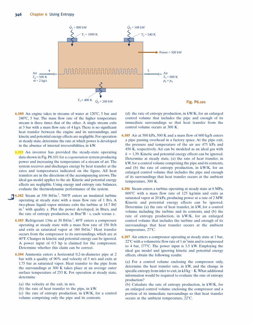
6.101 An inventor has provided the steady-state operating
data shown in Fig. P6.101 for a cogeneration system producing
power and increasing the temperature of a stream of air. The
system receives and discharges energy by heat transfer at the
rates and temperatures indicated on the figure. All heat
transfers are in the directions of the accompanying arrows. The
ideal gas model applies to the air. Kinetic and potential energy
effects are negligible. Using energy and entropy rate balances,
evaluate the thermodynamic performance of the system.
6.102 Steam at 550 lbf/in.2, 7008F enters an insulated turbine
operating at steady state with a mass flow rate of 1 lb/s. A
two-phase liquid–vapor mixture exits the turbine at 14.7 lbf/
in.2 with quality x. Plot the power developed, in Btu/s, and
the rate of entropy production, in Btu/8R ? s, each versus x.
6.103 Refrigerant 134a at 30 lbf/in.2, 408F enters a compressor
operating at steady state with a mass flow rate of 150 lb/h
and exits as saturated vapor at 160 lbf/in.2 Heat transfer
occurs from the compressor to its surroundings, which are at
408F. Changes in kinetic and potential energy can be ignored.
A power input of 0.5 hp is claimed for the compressor.
Determine whether this claim can be correct.
6.104 Ammonia enters a horizontal 0.2-m-diameter pipe at 2
bar with a quality of 90% and velocity of 5 m/s and exits at
1.75 bar as saturated vapor. Heat transfer to the pipe from
the surroundings at 300 K takes place at an average outer
surface temperature of 253 K. For operation at steady state,
determine
(a) the velocity at the exit, in m/s.
(b) the rate of heat transfer to the pipe, in kW.
(c) the rate of entropy production, in kW/K, for a control
volume comprising only the pipe and its contents.
Air
= 600 K
= p4
T5
p5
= 540 KT2= 1000 KT1
= 400 KT3
Power = 500 kW
Air
= 500 K
= 2 kg/s
T4
m·
= 200 kWQ3
·
= 108 kWQ2
·= 800 kWQ1
·
54
Fig. P6.101
c06UsingEntropy.indd Page 346 6/30/10 9:48:27 AM user-s146 c06UsingEntropy.indd Page 346 6/30/10 9:48:27 AM user-s146 /Users/user-s146/Desktop/Merry_X-Mas/New/Users/user-s146/Desktop/Merry_X-Mas/New

well insulated and the pressure is very nearly 1 atm
throughout. Assuming the ideal gas model for air with cp 5
0.24 Btu/lb ? 8R, and ignoring kinetic and potential energy
effects, determine (a) the temperature of the air at the exit,
in 8F, (b) the exit diameter, in ft, and (c) the rate of entropy
production within the duct, in Btu/min ? 8R.
6.112 Air flows through an insulated circular duct having a
diameter of 2 cm. Steady-state pressure and temperature data
obtained by measurements at two locations, denoted as 1 and
2, are given in the accompanying table. Modeling air as an
ideal gas with cp 5 1.005 kJ/kg ? K, determine (a) the direction
of the flow, (b) the velocity of the air, in m/s, at each of the
two locations, and (c) the mass flow rate of the air, in kg/s.
Measurement location 1 2
Pressure (kPa) 100 500Temperature (8C) 20 50
6.113 Determine the rates of entropy production, in Btu/min ? 8R,
for the steam generator and turbine of Example 4.10. Identify
the component that contributes more to inefficient operation
of the overall system.
6.114 Air as an ideal gas flows through the compressor and
heat exchanger shown in Fig. P6.114. A separate liquid water
stream also flows through the heat exchanger. The data
given are for operation at steady state. Stray heat transfer to
the surroundings can be neglected, as can all kinetic and
potential energy changes. Determine
(a) the compressor power, in kW, and the mass flow rate of
the cooling water, in kg/s.
(b) the rates of entropy production, each in kW/K, for the
compressor and heat exchanger.
6.108 Carbon monoxide (CO) enters a nozzle operating at
steady state at 25 bar, 2578C, and 45 m/s. At the nozzle exit,
the conditions are 2 bar, 578C, 560 m/s, respectively. The
carbon monoxide can be modeled as an ideal gas.
(a) For a control volume enclosing the nozzle only, determine
the heat transfer, in kJ, and the change in specific entropy,
in kJ/K, each per kg of carbon monoxide flowing through
the nozzle. What additional information would be required
to evaluate the rate of entropy production?
(b) Evaluate the rate of entropy production, in kJ/K per kg
of carbon monoxide flowing, for an enlarged control volume
enclosing the nozzle and a portion of its immediate
surroundings so that the heat transfer occurs at the ambient
temperature, 278C.
6.109 A counterflow heat exchanger operates at steady state
with negligible kinetic and potential energy effects. In one
stream, liquid water enters at 108C and exits at 208C with a
negligible change in pressure. In the other stream, Refrigerant
134a enters at 10 bar, 808C with a mass flow rate of 135 kg/h
and exits at 10 bar, 208C. The liquid water can be modeled
as incompressible with c 5 4.179 kJ/kg ? K. Heat transfer
from the outer surface of the heat exchanger can be ignored.
Determine
(a) the mass flow rate of the liquid water, in kg/h.
(b) the rate of entropy production within the heat exchanger,
in kW/K.
6.110 Saturated water vapor at 100 kPa enters a counterflow
heat exchanger operating at steady state and exits at 208C
with a negligible change in pressure. Ambient air at 275 K,
1 atm enters in a separate stream and exits at 290 K, 1 atm.
The air mass flow rate is 170 times that of the water. The air
can be modeled as an ideal gas with cp 5 1.005 kJ/kg ? K.
Kinetic and potential energy effects can be ignored.
(a) For a control volume enclosing the heat exchanger,
evaluate the rate of heat transfer, in kJ per kg of water
flowing.
(b) For an enlarged control volume that includes the heat
exchanger and enough of its immediate surroundings that
heat transfer from the control volume occurs at the ambient
temperature, 275 K, determine the rate of entropy production,
in kJ/K per kg of water flowing.
6.111 Figure P6.111 shows data for a portion of the ducting in
a ventilation system operating at steady state. The ducts are
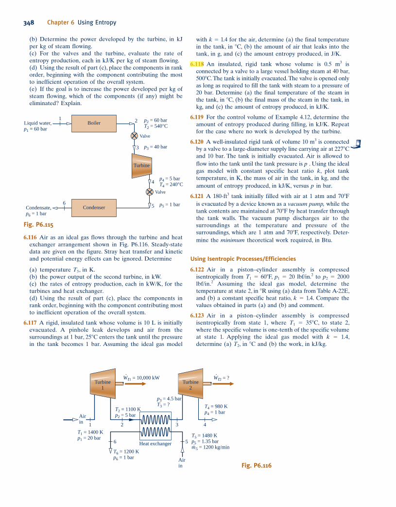
6.115 Figure P6.115 shows several components in series, all
operating at steady state. Liquid water enters the boiler at
60 bar. Steam exits the boiler at 60 bar, 5408C and undergoes
a throttling process to 40 bar before entering the turbine.
Steam expands adiabatically through the turbine to 5 bar,
2408C, and then undergoes a throttling process to 1 bar
before entering the condenser. Kinetic and potential energy
effects can be ignored.
(a) Locate each of the states 2–5 on a sketch of the T–s diagram.
Compressor
p1 = 96 kPa
T1 = 27°C
(AV)1 = 26.91 m3/min
p2 = 230 kPa
T2 = 127°C
TA = 25°C TB = 40°C
T3 = 77°C
p3 = p2
1Air in
32
Heat
exchanger
Water
in
(A)
Water
out
(B)
Fig. P6.114
Problems: Developing Engineering Skills 347
3
1
2
D1 = 4 ft
V1 = 400 ft/min
T1 = 80°F
V3 = 400 ft/min
T3 = ?
D3 = ?Insulation
(AV)2 = 2000 ft3/min
V2 = 600 ft/min
T2 = 40°F
Fig. P6.111
c06UsingEntropy.indd Page 347 5/26/10 3:30:11 PM user-s146 c06UsingEntropy.indd Page 347 5/26/10 3:30:11 PM user-s146 /Users/user-s146/Desktop/Merry_X-Mas/New/Users/user-s146/Desktop/Merry_X-Mas/New
348 Chapter 6 Using Entropy
with k 5 1.4 for the air, determine (a) the final temperature
in the tank, in 8C, (b) the amount of air that leaks into the
tank, in g, and (c) the amount entropy produced, in J/K.
6.118 An insulated, rigid tank whose volume is 0.5 m3 is
connected by a valve to a large vessel holding steam at 40 bar,
5008C. The tank is initially evacuated. The valve is opened only
as long as required to fill the tank with steam to a pressure of
20 bar. Determine (a) the final temperature of the steam in
the tank, in 8C, (b) the final mass of the steam in the tank, in
kg, and (c) the amount of entropy produced, in kJ/K.
6.119 For the control volume of Example 4.12, determine the
amount of entropy produced during filling, in kJ/K. Repeat
for the case where no work is developed by the turbine.
6.120 A well-insulated rigid tank of volume 10 m3 is connected
by a valve to a large-diameter supply line carrying air at 2278C
and 10 bar. The tank is initially evacuated. Air is allowed to
flow into the tank until the tank pressure is p . Using the ideal
gas model with constant specific heat ratio k, plot tank
temperature, in K, the mass of air in the tank, in kg, and the
amount of entropy produced, in kJ/K, versus p in bar.
6.121 A 180-ft3 tank initially filled with air at 1 atm and 708F
is evacuated by a device known as a vacuum pump, while the
tank contents are maintained at 708F by heat transfer through
the tank walls. The vacuum pump discharges air to the
surroundings at the temperature and pressure of the
surroundings, which are 1 atm and 708F, respectively. Deter-
mine the minimum theoretical work required, in Btu.
Using Isentropic Processes/Efficiencies
6.122 Air in a piston–cylinder assembly is compressed
isentropically from T1 5 608F, p1 5 20 lbf/in.2 to p2 5 2000
lbf/in.2 Assuming the ideal gas model, determine the
temperature at state 2, in 8R using (a) data from Table A-22E,
and (b) a constant specific heat ratio, k 5 1.4. Compare the
values obtained in parts (a) and (b) and comment.
6.123 Air in a piston–cylinder assembly is compressed
isentropically from state 1, where T1 5 358C, to state 2,
where the specific volume is one-tenth of the specific volume
at state 1. Applying the ideal gas model with k 5 1.4,
determine (a) T2, in 8C and (b) the work, in kJ/kg.
(b) Determine the power developed by the turbine, in kJ
per kg of steam flowing.
(c) For the valves and the turbine, evaluate the rate of
entropy production, each in kJ/K per kg of steam flowing.
(d) Using the result of part (c), place the components in rank
order, beginning with the component contributing the most
to inefficient operation of the overall system.
(e) If the goal is to increase the power developed per kg of
steam flowing, which of the components (if any) might be
eliminated? Explain.
Turbine
2
W· t2 = ?
T4 = 980 K
p4 = 1 bar
Turbine
1
W· t1 = 10,000 kW
T2 = 1100 K
p2 = 5 bar
T1 = 1400 K
p1 = 20 barT5 = 1480 K
p5 = 1.35 bar
m· 5 = 1200 kg/minT6 = 1200 K
p6 = 1 bar
Heat exchanger
Air
in
Air
in
p3 = 4.5 bar
T3 = ?
1 2
6
3 4
5
Fig. P6.116
Fig. P6.115
Liquid water,
p1 = 60 bar
Condensate,
p6 = 1 bar
p2 = 60 bar
T2 = 540°C
4p4 = 5 bar
T4 = 240°C
3 p3 = 40 bar
5 p5 = 1 bar
Boiler 21
Valve
Valve
Turbine
Condenser6
6.116 Air as an ideal gas flows through the turbine and heat
exchanger arrangement shown in Fig. P6.116. Steady-state
data are given on the figure. Stray heat transfer and kinetic
and potential energy effects can be ignored. Determine
(a) temperature T3, in K.
(b) the power output of the second turbine, in kW.
(c) the rates of entropy production, each in kW/K, for the
turbines and heat exchanger.
(d) Using the result of part (c), place the components in
rank order, beginning with the component contributing most
to inefficient operation of the overall system.
6.117 A rigid, insulated tank whose volume is 10 L is initially
evacuated. A pinhole leak develops and air from the
surroundings at 1 bar, 258C enters the tank until the pressure
in the tank becomes 1 bar. Assuming the ideal gas model
c06UsingEntropy.indd Page 348 6/30/10 9:48:27 AM user-s146 c06UsingEntropy.indd Page 348 6/30/10 9:48:27 AM user-s146 /Users/user-s146/Desktop/Merry_X-Mas/New/Users/user-s146/Desktop/Merry_X-Mas/New
6.136 The accompanying table provides steady-state data for
steam expanding adiabatically though a turbine. The states
are numbered as in Fig. 6.11. Kinetic and potential energy
effects can be ignored. Determine for the turbine (a) the work
developed per unit mass of steam flowing, in kJ/kg, (b) the
amount of entropy produced per unit mass of steam flowing,
in kJ/kg ? K, and (c) the isentropic turbine efficiency.
State p(bar) T(8C) x(%) h(kJ/kg) s(kJ/kg ? K)
1 10 300 — 3051 7.121 2s 0.10 45.81 86.3 — 7.121 2 0.10 45.81 90.0 — 7.400
6.137 The accompanying table provides steady-state data for
steam expanding adiabatically with a mass flow rate of 4 lb/s
through a turbine. Kinetic and potential energy effects can
be ignored. Determine for the turbine (a) the power
developed, in hp, (b) the rate of entropy production, in
hp/8R, and (c) the isentropic turbine efficiency.
p(lbf/in.2) T(8F) u(Btu/lb) h(Btu/lb) s(Btu/lb ? 8R)
Inlet 140 1000 1371.0 1531.0 1.8827Exit 2 270 1101.4 1181.7 2.0199
6.124 Propane undergoes an isentropic expansion from an initial
state where T1 5 408C, p1 5 1 MPa to a final state where the
temperature and pressure are T2, p2, respectively. Determine
(a) p2, in kPa, when T2 5 2408C.
(b) T2, in 8C, when p2 5 0.8 MPa.
6.125 Argon in a piston–cylinder assembly is compressed
isentropically from state 1, where p1 5 150 kPa, T1 5 358C, to
state 2, where p2 5 300 kPa. Assuming the ideal gas model
with k 5 1.67, determine (a) T2, in 8C, and (b) the work, in kJ
per kg of argon.
6.126 Air within a piston–cylinder assembly, initially at 12 bar,
620 K, undergoes an isentropic expansion to 1.4 bar.
Assuming the ideal gas model for the air, determine the final
temperature, in K, and the work, in kJ/kg. Solve two ways:
using (a) data from Table A-22 and (b) k 5 1.4.
6.127 Air within a piston–cylinder assembly, initially at 30 lbf/
in.2, 5108R, and a volume of 6 ft3, is compressed isentropically
to a final volume of 1.2 ft3. Assuming the ideal gas model
with k 5 1.4 for the air, determine the (a) mass, in lb,
(b) final pressure, in lbf/in.2, (c) final temperature, in 8R, and
(d) work, in Btu.
6.128 Air contained in a piston–cylinder assembly, initially at
4 bar, 600 K and a volume of 0.43 m3, expands isentropically
to a pressure of 1.5 bar. Assuming the ideal gas model for
the air, determine the (a) mass, in kg, (b) final temperature,
in K, and (c) work, in kJ.
6.129 Air in a piston–cylinder assembly is compressed
isentropically from an initial state where T1 5 340 K to a
final state where the pressure is 90% greater than at state 1.
Assuming the ideal gas model, determine (a) T2, in K, and
(b) the work, in kJ/kg.
6.130 A rigid, insulated tank with a volume of 20 m3 is filled
initially with air at 10 bar, 500 K. A leak develops, and air
slowly escapes until the pressure of the air remaining in the
tank is 5 bar. Employing the ideal gas model with k 5 1.4
for the air, determine the amount of mass remaining in the
tank, in kg, and its temperature, in K.
6.131 A rigid, insulated tank with a volume of 21.61 ft3 is filled
initially with air at 110 lbf/in.2, 5358R. A leak develops, and
air slowly escapes until the pressure of the air remaining in
the tank is 15 lbf/in.2 Employing the ideal gas model with
k 5 1.4 for the air, determine the amount of mass remaining
in the tank, in lb, and its temperature, in 8R.
6.132 The accompanying table provides steady-state data for an
isentropic expansion of steam through a turbine. For a mass
flow rate of 2.55 kg/s, determine the power developed by the
turbine, in MW. Ignore the effects of potential energy.
p(bar) T(8C) V(m/s) h(kJ/kg) s(kJ/kg ? K)
Inlet 10 300 25 3051.1 7.1214Exit 1.5 — 100 7.1214
6.133 Water vapor enters a turbine operating at steady state
at 10008F, 140 lbf/in.2, with a volumetric flow rate of 21.6 ft3/s,
and expands isentropically to 2 lbf/in.2 Determine the power
developed by the turbine, in hp. Ignore kinetic and potential
energy effects.
Steam
generator
Turbine
Power
in
Cooling
water in
Pump
Condenser
Cooling
water out
p4 = 20 MPa
p3 = 0.20 bar
T3 = 40°C
p1 = 20 MPa
T1 = 700°C
Q· in
p2 = 0.20 bar
4
1
3
2
Power out
Fig. P6.135
6.134 Air enters a turbine operating at steady state at 6 bar
and 1100 K and expands isentropically to a state where the
temperature is 700 K. Employing the ideal gas model with
data from Table A-22, and ignoring kinetic and potential
energy changes, determine the pressure at the exit, in bar,
and the work, in kJ per kg of air flowing.
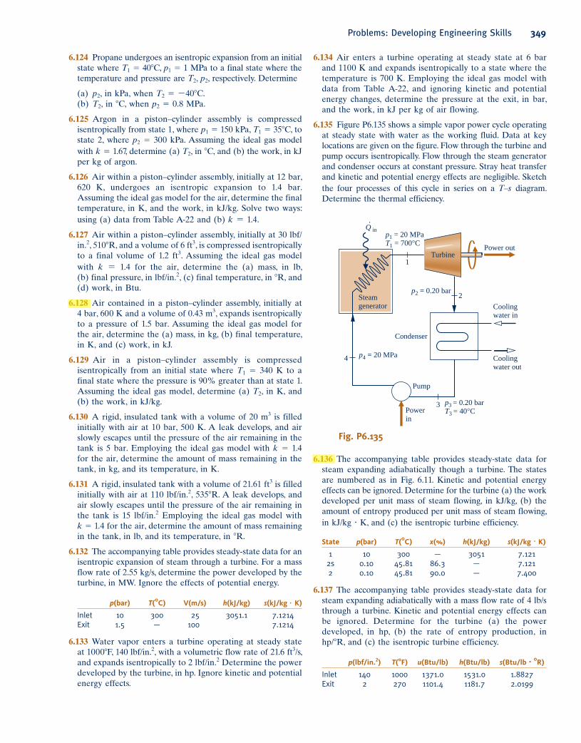
6.135 Figure P6.135 shows a simple vapor power cycle operating
at steady state with water as the working fluid. Data at key
locations are given on the figure. Flow through the turbine and
pump occurs isentropically. Flow through the steam generator
and condenser occurs at constant pressure. Stray heat transfer
and kinetic and potential energy effects are negligible. Sketch
the four processes of this cycle in series on a T–s diagram.
Determine the thermal efficiency.
Problems: Developing Engineering Skills 349
c06UsingEntropy.indd Page 349 5/28/10 1:23:28 PM user-s146 c06UsingEntropy.indd Page 349 5/28/10 1:23:28 PM user-s146 /Users/user-s146/Desktop/Merry_X-Mas/New/Users/user-s146/Desktop/Merry_X-Mas/New

350 Chapter 6 Using Entropy
92%. Stray heat transfer and kinetic and potential energy
effects are negligible. Determine the power developed by
the turbine, in hp.
6.147 Air enters the compressor of a gas turbine power plant
operating at steady state at 290 K, 100 kPa and exits at
420 K, 330 kPa. Stray heat transfer and kinetic and potential
energy effects are negligible. Using the ideal gas model for
air, determine the isentropic compressor efficiency.
6.148 Air at 258C, 100 kPa enters a compressor operating at
steady state and exits at 2608C, 650 kPa. Stray heat transfer
and kinetic and potential energy effects are negligible.
Modeling air as an ideal gas with k 5 1.4, determine the
isentropic compressor efficiency.
6.149 Air at 290 K, 100 kPa enters a compressor operating at
steady state and is compressed adiabatically to an exit state
of 420 K, 330 kPa. The air is modeled as an ideal gas, and
kinetic and potential energy effects are negligible. For the
compressor, (a) determine the rate of entropy production, in
kJ/K per kg of air flowing, and (b) the isentropic compressor
efficiency.
6.150 Carbon dioxide (CO2) at 1 bar, 300 K enters a compressor
operating at steady state and is compressed adiabatically to
an exit state of 10 bar, 520 K. The CO2 is modeled as an
ideal gas, and kinetic and potential energy effects are
negligible. For the compressor, determine (a) the work input,
in kJ per kg of CO2 flowing, (b) the rate of entropy production,
in kJ/K per kg of CO2 flowing, and (c) the isentropic
compressor efficiency.
6.151 Air at 300 K, 1 bar enters a compressor operating at
steady state and is compressed adiabatically to 1.5 bar. The
power input is 42 kJ per kg of air flowing. Employing the
ideal gas model with k 5 1.4 for the air, determine for the
compressor (a) the rate of entropy production, in kJ/K per
kg of air flowing, and (b) the isentropic compressor efficiency.
Ignore kinetic and potential energy effects.
6.152 Air at 1 atm, 5208R enters a compressor operating at
steady state and is compressed adiabatically to 3 atm. The
isentropic compressor efficiency is 80%. Employing the ideal
gas model with k 5 1.4 for the air, determine for the
compressor (a) the power input, in Btu per lb of air flowing,
and (b) the amount of entropy produced, in Btu/8R per lb
of air flowing. Ignore kinetic and potential energy effects.
6.153 Nitrogen (N2) enters an insulated compressor operating at
steady state at 1 bar, 378C with a mass flow rate of 1000 kg/h
and exits at 10 bar. Kinetic and potential energy effects are
negligible. The nitrogen can be modeled as an ideal gas with
k 5 1.391.
(a) Determine the minimum theoretical power input
required, in kW, and the corresponding exit temperature,
in 8C.
(b) If the exit temperature is 3978C, determine the power
input, in kW, and the isentropic compressor efficiency.
6.154 Saturated water vapor at 3008F enters a compressor
operating at steady state with a mass flow rate of 5 lb/s and
is compressed adiabatically to 800 lbf/in.2 If the power input
is 2150 hp, determine for the compressor (a) the isentropic
6.138 Water vapor at 800 lbf/in.2, 10008F enters a turbine
operating at steady state and expands adiabatically to 2 lbf/
in.2, developing work at a rate of 490 Btu per lb of vapor
flowing. Determine the condition at the turbine exit: two-
phase liquid–vapor or superheated vapor? Also, evaluate the
isentropic turbine efficiency. Kinetic and potential energy
effects are negligible.
6.139 Air at 1600 K, 30 bar enters a turbine operating at steady
state and expands adiabatically to the exit, where the
temperature is 830 K. If the isentropic turbine efficiency is
90%, determine (a) the pressure at the exit, in bar, and (b) the
work developed, in kJ per kg of air flowing. Assume ideal
gas behavior for the air and ignore kinetic and potential
energy effects.
6.140 Water vapor at 5 bar, 3208C enters a turbine operating
at steady state with a volumetric flow rate of 0.65 m3/s and
expands adiabatically to an exit state of 1 bar, 1608C. Kinetic
and potential energy effects are negligible. Determine for
the turbine (a) the power developed, in kW, (b) the rate of
entropy production, in kW/K, and (c) the isentropic turbine
efficiency.
6.141 Air at 1175 K, 8 bar enters a turbine operating at steady
state and expands adiabatically to 1 bar. The isentropic
turbine efficiency is 92%. Employing the ideal gas model
with k 5 1.4 for the air, determine (a) the work developed
by the turbine, in kJ per kg of air flowing, and (b) the
temperature at the exit, in K. Ignore kinetic and potential
energy effects.
6.142 Water vapor at 10 MPa, 6008C enters a turbine operating
at steady state with a volumetric flow rate of 0.36 m3 and
exits at 0.1 bar and a quality of 92%. Stray heat transfer and
kinetic and potential energy effects are negligible. Determine
for the turbine (a) the mass flow rate, in kg/s, (b) the power
developed by the turbine, in MW, (c) the rate at which
entropy is produced, in kW/K, and (d) the isentropic turbine
efficiency.
6.143 Air modeled as an ideal gas enters a turbine operating at
steady state at 1040 K, 278 kPa and exits at 120 kPa. The mass
flow rate is 5.5 kg/s, and the power developed is 1120 kW.
Stray heat transfer and kinetic and potential energy effects
are negligible. Determine (a) the temperature of the air at the
turbine exit, in K, and (b) the isentropic turbine efficiency.
6.144 Water vapor at 10008F, 140 lbf/in.2 enters a turbine
operating at steady state and expands to 2 lbf/in.2 The mass
flow rate is 4 lb/s and the power developed is 1600 Btu/s.
Stray heat transfer and kinetic and potential energy effects
are negligible. Determine the isentropic turbine efficiency.
6.145 Water vapor at 6 MPa, 6008C enters a turbine operating
at steady state and expands to 10 kPa. The mass flow rate
is 2 kg/s, and the power developed is 2626 kW. Stray heat
transfer and kinetic and potential energy effects are
negligible. Determine (a) the isentropic turbine efficiency
and (b) the rate of entropy production within the turbine,
in kW/K.
6.146 Water vapor at 800 lbf/in.2, 10008F enters a turbine
operating at steady state and expands to 2 lbf/in.2 The mass
flow rate is 5.56 lb/s, and the isentropic turbine efficiency is
c06UsingEntropy.indd Page 350 5/28/10 1:23:36 PM user-s146 c06UsingEntropy.indd Page 350 5/28/10 1:23:36 PM user-s146 /Users/user-s146/Desktop/Merry_X-Mas/New/Users/user-s146/Desktop/Merry_X-Mas/New
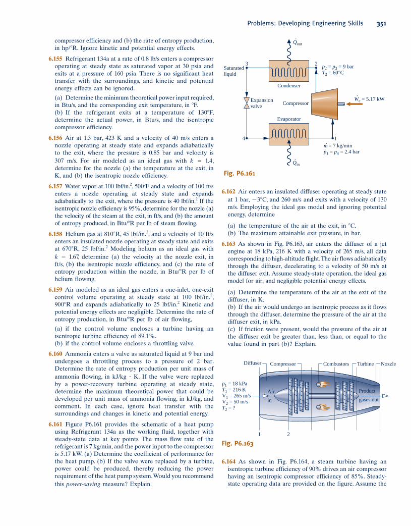
compressor efficiency and (b) the rate of entropy production,
in hp/8R. Ignore kinetic and potential energy effects.
6.155 Refrigerant 134a at a rate of 0.8 lb/s enters a compressor
operating at steady state as saturated vapor at 30 psia and
exits at a pressure of 160 psia. There is no significant heat
transfer with the surroundings, and kinetic and potential
energy effects can be ignored.
(a) Determine the minimum theoretical power input required,
in Btu/s, and the corresponding exit temperature, in 8F.
(b) If the refrigerant exits at a temperature of 1308F,
determine the actual power, in Btu/s, and the isentropic
compressor efficiency.
6.156 Air at 1.3 bar, 423 K and a velocity of 40 m/s enters a
nozzle operating at steady state and expands adiabatically
to the exit, where the pressure is 0.85 bar and velocity is
307 m/s. For air modeled as an ideal gas with k 5 1.4,
determine for the nozzle (a) the temperature at the exit, in
K, and (b) the isentropic nozzle efficiency.
6.157 Water vapor at 100 lbf/in.2, 5008F and a velocity of 100 ft/s
enters a nozzle operating at steady state and expands
adiabatically to the exit, where the pressure is 40 lbf/in.2 If the
isentropic nozzle efficiency is 95%, determine for the nozzle (a)
the velocity of the steam at the exit, in ft/s, and (b) the amount
of entropy produced, in Btu/8R per lb of steam flowing.
6.158 Helium gas at 8108R, 45 lbf/in.2, and a velocity of 10 ft/s
enters an insulated nozzle operating at steady state and exits
at 6708R, 25 lbf/in.2 Modeling helium as an ideal gas with
k 5 1.67, determine (a) the velocity at the nozzle exit, in
ft/s, (b) the isentropic nozzle efficiency, and (c) the rate of
entropy production within the nozzle, in Btu/8R per lb of
helium flowing.
6.159 Air modeled as an ideal gas enters a one-inlet, one-exit
control volume operating at steady state at 100 lbf/in.2,
9008R and expands adiabatically to 25 lbf/in.2 Kinetic and
potential energy effects are negligible. Determine the rate of
entropy production, in Btu/8R per lb of air flowing,
(a) if the control volume encloses a turbine having an
isentropic turbine efficiency of 89.1%.
(b) if the control volume encloses a throttling valve.
6.160 Ammonia enters a valve as saturated liquid at 9 bar and
undergoes a throttling process to a pressure of 2 bar.
Determine the rate of entropy production per unit mass of
ammonia flowing, in kJ/kg ? K. If the valve were replaced
by a power-recovery turbine operating at steady state,
determine the maximum theoretical power that could be
developed per unit mass of ammonia flowing, in kJ/kg, and
comment. In each case, ignore heat transfer with the
surroundings and changes in kinetic and potential energy.
6.161 Figure P6.161 provides the schematic of a heat pump
using Refrigerant 134a as the working fluid, together with
steady-state data at key points. The mass flow rate of the
refrigerant is 7 kg/min, and the power input to the compressor
is 5.17 kW. (a) Determine the coefficient of performance for
the heat pump. (b) If the valve were replaced by a turbine,
power could be produced, thereby reducing the power
requirement of the heat pump system. Would you recommend
this power-saving measure? Explain.
4 1
3 2
Condenser
Evaporator
Compressor
Qout
·
Qin
·
Wc = 5.17 kW·
Expansion
valve
Saturated
liquid
m· = 7 kg/min
p1 = p4 = 2.4 bar
p2 = p3 = 9 bar
T2 = 60°C
Fig. P6.161
6.162 Air enters an insulated diffuser operating at steady state
at 1 bar, 238C, and 260 m/s and exits with a velocity of 130
m/s. Employing the ideal gas model and ignoring potential
energy, determine
(a) the temperature of the air at the exit, in 8C.
(b) The maximum attainable exit pressure, in bar.
6.163 As shown in Fig. P6.163, air enters the diffuser of a jet
engine at 18 kPa, 216 K with a velocity of 265 m/s, all data
corresponding to high-altitude flight. The air flows adiabatically
through the diffuser, decelerating to a velocity of 50 m/s at
the diffuser exit. Assume steady-state operation, the ideal gas
model for air, and negligible potential energy effects.
(a) Determine the temperature of the air at the exit of the
diffuser, in K.
(b) If the air would undergo an isentropic process as it flows
through the diffuser, determine the pressure of the air at the
diffuser exit, in kPa.
(c) If friction were present, would the pressure of the air at
the diffuser exit be greater than, less than, or equal to the
value found in part (b)? Explain.
Compressor CombustorsDiffuser Turbine
Product
gases out
Nozzle
Air
in
1 2
p1 = 18 kPa
T1 = 216 K
V1 = 265 m/s
V2 = 50 m/s
T2 = ?
Fig. P6.163
Problems: Developing Engineering Skills 351
6.164 As shown in Fig. P6.164, a steam turbine having an
isentropic turbine efficiency of 90% drives an air compressor
having an isentropic compressor efficiency of 85%. Steady-
state operating data are provided on the figure. Assume the
c06UsingEntropy.indd Page 351 5/28/10 1:23:41 PM user-s146 c06UsingEntropy.indd Page 351 5/28/10 1:23:41 PM user-s146 /Users/user-s146/Desktop/Merry_X-Mas/New/Users/user-s146/Desktop/Merry_X-Mas/New

352 Chapter 6 Using Entropy
6.166 Figure P6.166 shows a power system operating at steady
state consisting of three components in series: an air
compressor having an isentropic compressor efficiency of
80%, a heat exchanger, and a turbine having an isentropic
turbine efficiency of 90%. Air enters the compressor at 1 bar,
300 K with a mass flow rate of 5.8 kg/s and exits at a pressure
of 10 bar. Air enters the turbine at 10 bar, 1400 K and exits
at a pressure of 1 bar. Air can be modeled as an ideal gas.
Stray heat transfer and kinetic and potential energy effects
are negligible. Determine, in kW, (a) the power required by
the compressor, (b) the power developed by the turbine, and
(c) the net power output of the overall power system.
ideal gas model for air, and ignore stray heat transfer and
kinetic and potential energy effects.
(a) Determine the mass flow rate of the steam entering the
turbine, in kg of steam per kg of air exiting the compressor.
(b) Repeat part (a) if ht 5 hc 5 100%
p1 = 1 bar
T1 = 300 K
m· = 5.8 kg/s
p4 = 1 bar
p3 = 10 bar
T3 = 1400 K
ηt = 90%ηc = 80%
p2 = 10 bar Heat exchanger
TurbineCompressor
4
2 3
Q·in
1
W·
net
Fig. P6.166
6.165 Figure P6.165 shows a simple vapor power plant
operating at steady state with water as the working fluid.
Data at key locations are given on the figure. The mass flow
rate of the water circulating through the components is 109
kg/s. Stray heat transfer and kinetic and potential energy
effects can be ignored. Determine
(a) the net power developed, in MW.
(b) the thermal efficiency.
(c) the isentropic turbine efficiency.
(d) the isentropic pump efficiency.
(e) the mass flow rate of the cooling water, in kg/s.
(f) the rates of entropy production, each in kW/K, for the
turbine, condenser, and pump.
Second-stage
turbine
First-stage
turbineSteam
1 2 3
p1 = 600 lbf/in.2
T1 = 800°F
p2 = 250 lbf/in.2 p3 = 14.7 lbf/in.2
ηt1 = 85% ηt2 = 91%
Fig. P6.167
Turbine Compressor
p1 = 2 MPa
T1 = 440°C
Steam
Air
p4 = 496 kPa1
2T3 = 27°C,
p3 = 110 kPa
p2 = 100 kPa
ηt = 90% ηc = 85%
3
4
Fig. P6.164
Steam
generator
Turbine
Power
in
Cooling
water in at 20°C
Pump
Condenser
Cooling
water out at 35°C
p4 = 100 bar
T4 = 43°C
p3 = 0.08 bar
Saturated liquid
p1 = 100 bar
T1 = 520°C
Q· in
p2 = 0.08 bar
x2 = 90%
4
1
3
2
Power out
Fig. P6.165
6.167 As shown in Fig. P6.167, a well-insulated turbine operating
at steady state has two stages in series. Steam enters the first
stage at 8008F, 600 lbf/in.2 and exits at 250 lbf/in.2 The steam
then enters the second stage and exits at 14.7 lbf/in.2 The
isentropic efficiencies of the stages are 85% and 91%,
respectively. Show the principal states on a T–s diagram. At
the exit of the second stage, determine the temperature, in
8F, if superheated vapor exits or the quality if a two-phase
liquid–vapor mixture exits. Also determine the work
developed by each stage, in Btu per lb of steam flowing.
6.168 A rigid tank is filled initially with 5.0 kg of air at a
pressure of 0.5 MPa and a temperature of 500 K. The air is
allowed to discharge through a turbine into the atmosphere,
developing work until the pressure in the tank has fallen to
the atmospheric level of 0.1 MPa. Employing the ideal gas
model for the air, determine the maximum theoretical
amount of work that could be developed, in kJ. Ignore heat
transfer with the atmosphere and changes in kinetic and
potential energy.
c06UsingEntropy.indd Page 352 5/26/10 3:30:28 PM user-s146 c06UsingEntropy.indd Page 352 5/26/10 3:30:28 PM user-s146 /Users/user-s146/Desktop/Merry_X-Mas/New/Users/user-s146/Desktop/Merry_X-Mas/New
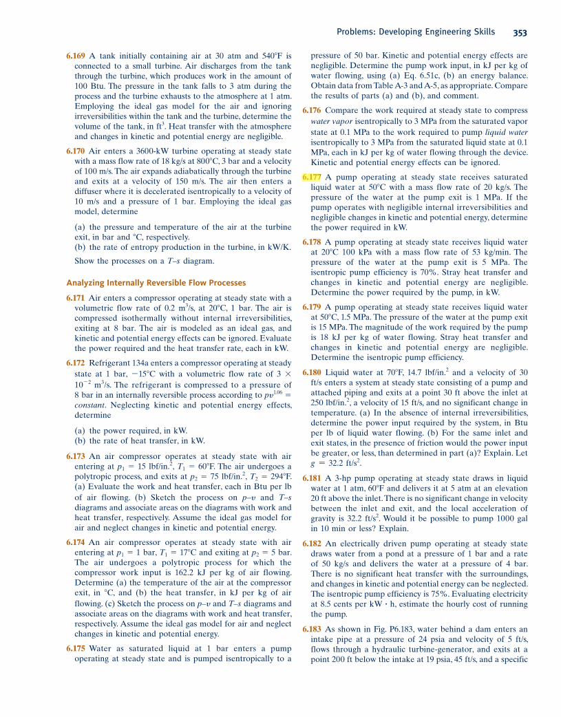
pressure of 50 bar. Kinetic and potential energy effects are
negligible. Determine the pump work input, in kJ per kg of
water flowing, using (a) Eq. 6.51c, (b) an energy balance.
Obtain data from Table A-3 and A-5, as appropriate. Compare
the results of parts (a) and (b), and comment.
6.176 Compare the work required at steady state to compress
water vapor isentropically to 3 MPa from the saturated vapor
state at 0.1 MPa to the work required to pump liquid water isentropically to 3 MPa from the saturated liquid state at 0.1
MPa, each in kJ per kg of water flowing through the device.
Kinetic and potential energy effects can be ignored.
6.177 A pump operating at steady state receives saturated
liquid water at 508C with a mass flow rate of 20 kg/s. The
pressure of the water at the pump exit is 1 MPa. If the
pump operates with negligible internal irreversibilities and
negligible changes in kinetic and potential energy, determine
the power required in kW.
6.178 A pump operating at steady state receives liquid water
at 208C 100 kPa with a mass flow rate of 53 kg/min. The
pressure of the water at the pump exit is 5 MPa. The
isentropic pump efficiency is 70%. Stray heat transfer and
changes in kinetic and potential energy are negligible.
Determine the power required by the pump, in kW.
6.179 A pump operating at steady state receives liquid water
at 508C, 1.5 MPa. The pressure of the water at the pump exit
is 15 MPa. The magnitude of the work required by the pump
is 18 kJ per kg of water flowing. Stray heat transfer and
changes in kinetic and potential energy are negligible.
Determine the isentropic pump efficiency.
6.180 Liquid water at 708F, 14.7 lbf/in.2 and a velocity of 30
ft/s enters a system at steady state consisting of a pump and
attached piping and exits at a point 30 ft above the inlet at
250 lbf/in.2, a velocity of 15 ft/s, and no significant change in
temperature. (a) In the absence of internal irreversibilities,
determine the power input required by the system, in Btu
per lb of liquid water flowing. (b) For the same inlet and
exit states, in the presence of friction would the power input
be greater, or less, than determined in part (a)? Explain. Let
g 5 32.2 ft/s2.
6.181 A 3-hp pump operating at steady state draws in liquid
water at 1 atm, 608F and delivers it at 5 atm at an elevation
20 ft above the inlet. There is no significant change in velocity
between the inlet and exit, and the local acceleration of
gravity is 32.2 ft/s2. Would it be possible to pump 1000 gal
in 10 min or less? Explain.
6.182 An electrically driven pump operating at steady state
draws water from a pond at a pressure of 1 bar and a rate
of 50 kg/s and delivers the water at a pressure of 4 bar.
There is no significant heat transfer with the surroundings,
and changes in kinetic and potential energy can be neglected.
The isentropic pump efficiency is 75%. Evaluating electricity
at 8.5 cents per kW ? h, estimate the hourly cost of running
the pump.
6.183 As shown in Fig. P6.183, water behind a dam enters an
intake pipe at a pressure of 24 psia and velocity of 5 ft/s,
flows through a hydraulic turbine-generator, and exits at a
point 200 ft below the intake at 19 psia, 45 ft/s, and a specific
6.169 A tank initially containing air at 30 atm and 5408F is
connected to a small turbine. Air discharges from the tank
through the turbine, which produces work in the amount of
100 Btu. The pressure in the tank falls to 3 atm during the
process and the turbine exhausts to the atmosphere at 1 atm.
Employing the ideal gas model for the air and ignoring
irreversibilities within the tank and the turbine, determine the
volume of the tank, in ft3. Heat transfer with the atmosphere
and changes in kinetic and potential energy are negligible.
6.170 Air enters a 3600-kW turbine operating at steady state
with a mass flow rate of 18 kg/s at 8008C, 3 bar and a velocity
of 100 m/s. The air expands adiabatically through the turbine
and exits at a velocity of 150 m/s. The air then enters a
diffuser where it is decelerated isentropically to a velocity of
10 m/s and a pressure of 1 bar. Employing the ideal gas
model, determine
(a) the pressure and temperature of the air at the turbine
exit, in bar and 8C, respectively.
(b) the rate of entropy production in the turbine, in kW/K.
Show the processes on a T–s diagram.
Analyzing Internally Reversible Flow Processes
6.171 Air enters a compressor operating at steady state with a
volumetric flow rate of 0.2 m3/s, at 208C, 1 bar. The air is
compressed isothermally without internal irreversibilities,
exiting at 8 bar. The air is modeled as an ideal gas, and
kinetic and potential energy effects can be ignored. Evaluate
the power required and the heat transfer rate, each in kW.
6.172 Refrigerant 134a enters a compressor operating at steady
state at 1 bar, 2158C with a volumetric flow rate of 3 3
1022 m3/s. The refrigerant is compressed to a pressure of
8 bar in an internally reversible process according to py1.06 5
constant. Neglecting kinetic and potential energy effects,
determine
(a) the power required, in kW.
(b) the rate of heat transfer, in kW.
6.173 An air compressor operates at steady state with air
entering at p1 5 15 lbf/in.2, T1 5 608F. The air undergoes a
polytropic process, and exits at p2 5 75 lbf/in.2, T2 5 2948F.
(a) Evaluate the work and heat transfer, each in Btu per lb
of air flowing. (b) Sketch the process on p–y and T–s diagrams and associate areas on the diagrams with work and
heat transfer, respectively. Assume the ideal gas model for
air and neglect changes in kinetic and potential energy.
6.174 An air compressor operates at steady state with air
entering at p1 5 1 bar, T1 5 178C and exiting at p2 5 5 bar.
The air undergoes a polytropic process for which the
compressor work input is 162.2 kJ per kg of air flowing.
Determine (a) the temperature of the air at the compressor
exit, in 8C, and (b) the heat transfer, in kJ per kg of air
flowing. (c) Sketch the process on p–y and T–s diagrams and
associate areas on the diagrams with work and heat transfer,
respectively. Assume the ideal gas model for air and neglect
changes in kinetic and potential energy.
6.175 Water as saturated liquid at 1 bar enters a pump
operating at steady state and is pumped isentropically to a
Problems: Developing Engineering Skills 353
c06UsingEntropy.indd Page 353 5/26/10 3:30:36 PM user-s146 c06UsingEntropy.indd Page 353 5/26/10 3:30:36 PM user-s146 /Users/user-s146/Desktop/Merry_X-Mas/New/Users/user-s146/Desktop/Merry_X-Mas/New
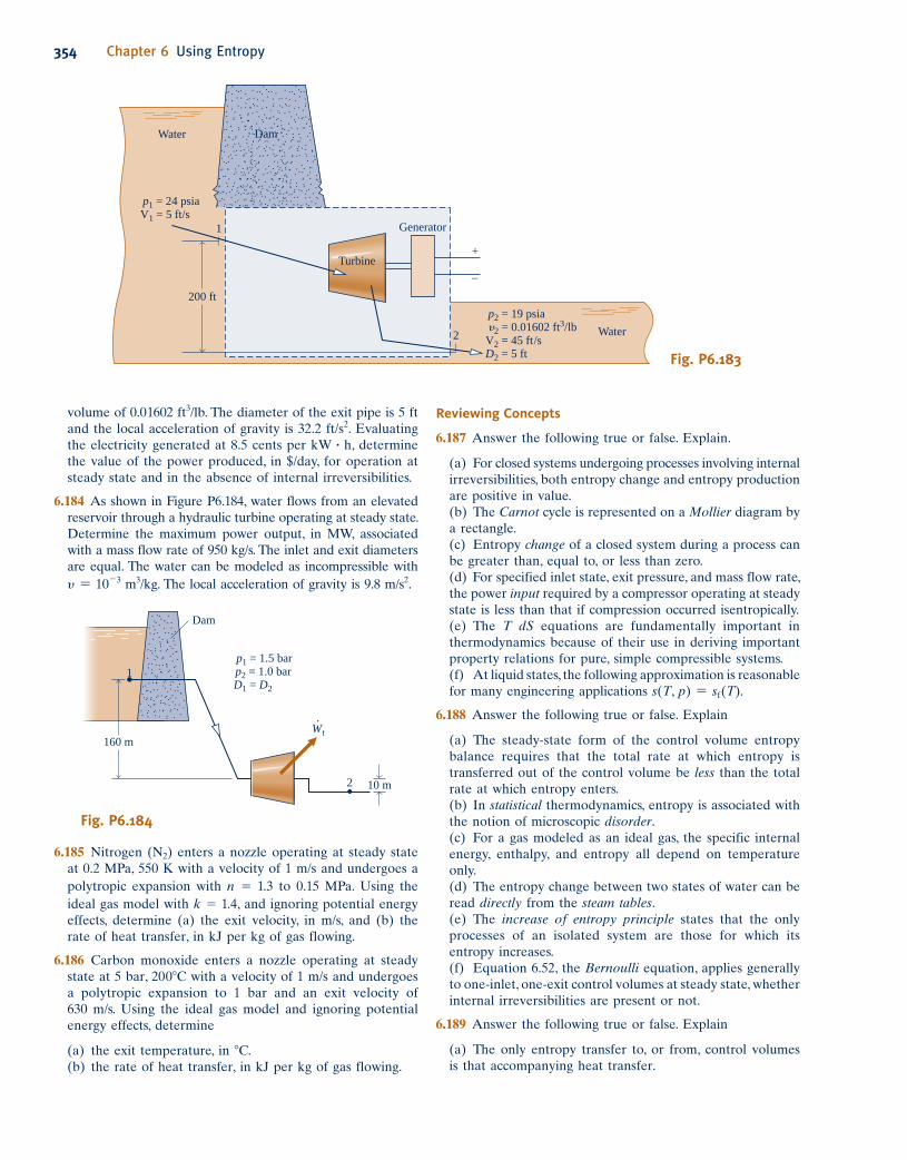
354 Chapter 6 Using Entropy
6.185 Nitrogen (N2) enters a nozzle operating at steady state
at 0.2 MPa, 550 K with a velocity of 1 m/s and undergoes a
polytropic expansion with n 5 1.3 to 0.15 MPa. Using the
ideal gas model with k 5 1.4, and ignoring potential energy
effects, determine (a) the exit velocity, in m/s, and (b) the
rate of heat transfer, in kJ per kg of gas flowing.
6.186 Carbon monoxide enters a nozzle operating at steady
state at 5 bar, 2008C with a velocity of 1 m/s and undergoes
a polytropic expansion to 1 bar and an exit velocity of
630 m/s. Using the ideal gas model and ignoring potential
energy effects, determine
(a) the exit temperature, in 8C.
(b) the rate of heat transfer, in kJ per kg of gas flowing.
Reviewing Concepts
6.187 Answer the following true or false. Explain.
(a) For closed systems undergoing processes involving internal
irreversibilities, both entropy change and entropy production
are positive in value.
(b) The Carnot cycle is represented on a Mollier diagram by
a rectangle.
(c) Entropy change of a closed system during a process can
be greater than, equal to, or less than zero.
(d) For specified inlet state, exit pressure, and mass flow rate,
the power input required by a compressor operating at steady
state is less than that if compression occurred isentropically.
(e) The T dS equations are fundamentally important in
thermodynamics because of their use in deriving important
property relations for pure, simple compressible systems.
(f) At liquid states, the following approximation is reasonable
for many engineering applications s(T, p) 5 sf(T).
6.188 Answer the following true or false. Explain
(a) The steady-state form of the control volume entropy
balance requires that the total rate at which entropy is
transferred out of the control volume be less than the total
rate at which entropy enters.
(b) In statistical thermodynamics, entropy is associated with
the notion of microscopic disorder.
(c) For a gas modeled as an ideal gas, the specific internal
energy, enthalpy, and entropy all depend on temperature
only.
(d) The entropy change between two states of water can be
read directly from the steam tables.
(e) The increase of entropy principle states that the only
processes of an isolated system are those for which its
entropy increases.
(f) Equation 6.52, the Bernoulli equation, applies generally
to one-inlet, one-exit control volumes at steady state, whether
internal irreversibilities are present or not.
6.189 Answer the following true or false. Explain
(a) The only entropy transfer to, or from, control volumes
is that accompanying heat transfer.
volume of 0.01602 ft3/lb. The diameter of the exit pipe is 5 ft
and the local acceleration of gravity is 32.2 ft/s2. Evaluating
the electricity generated at 8.5 cents per kW ? h, determine
the value of the power produced, in $/day, for operation at
steady state and in the absence of internal irreversibilities.
6.184 As shown in Figure P6.184, water flows from an elevated
reservoir through a hydraulic turbine operating at steady state.
Determine the maximum power output, in MW, associated
with a mass flow rate of 950 kg/s. The inlet and exit diameters
are equal. The water can be modeled as incompressible with
y 5 1023 m3/kg. The local acceleration of gravity is 9.8 m/s2.
Turbine
200 ft
Generator
Water
Water2
1
p1 = 24 psia
V1 = 5 ft/s
p2 = 19 psia
�2 = 0.01602 ft3/lb
V2 = 45 ft/s
D2 = 5 ft
+
–
Dam
Fig. P6.183
p1 = 1.5 bar
p2 = 1.0 bar
D1 = D2
160 m
10 m
Dam
2
1
W·
t
Fig. P6.184
c06UsingEntropy.indd Page 354 5/26/10 3:53:47 PM user-s146 c06UsingEntropy.indd Page 354 5/26/10 3:53:47 PM user-s146 /Users/user-s146/Desktop/Merry_X-Mas/New/Users/user-s146/Desktop/Merry_X-Mas/New
c DESIGN & OPEN-ENDED PROBLEMS: EXPLORING ENGINEERING PRACTICE
6.1D Using the ENERGY STAR® home improvement tool
box, obtain a rank-ordered list of the top three cost-effective
improvements that would enhance the overall energy efficiency
of your home. Develop a plan to implement the improvements.
Write a report, including at least three references.
6.2D Ocean thermal energy conversion (OTEC) power plants
generate electricity on ships or platforms at sea by exploiting
the naturally occurring decrease of the temperature of ocean
water with depth. One proposal for the use of OTEC-
generated electricity is to produce and commercialize
ammonia in three steps: Hydrogen (H2) would first be
obtained by electrolysis of desalted sea water. The hydrogen
then would be reacted with nitrogen (N2) from the
atmosphere to obtain ammonia (NH3). Finally, liquid
ammonia would be shipped to shore, where it would be
reprocessed into hydrogen or used as a feedstock. Some say
a major drawback with the proposal is whether current technology can be integrated to provide cost-competitive
end products. Investigate this issue and summarize your
findings in a report with at least three references.
6.3D Natural gas is currently playing a significant role in
meeting our energy needs and hydrogen may be just as
important in years ahead. For natural gas and hydrogen,
energy is required at every stage of distribution between
production and end use: for storage, transportation by
pipelines, trucks, trains and ships, and liquefaction, if needed.
According to some observers, distribution energy requirements
will weigh more heavily on hydrogen not only because it has
special attributes but also because means for distributing it
are less developed than for natural gas. Investigate the energy
requirements for distributing hydrogen relative to that for
natural gas. Write a report with at least three references.
6.4D For a compressor or pump located at your campus or
workplace, take data sufficient for evaluating the isentropic
compressor or pump efficiency. Compare the experimentally
determined isentropic efficiency with data provided by the
manufacturer. Rationalize any significant discrepancy
between experimental and manufacturer values. Prepare a
technical report including a full description of instrumentation,
recorded data, results and conclusions, and at least three
references.
6.5D Classical economics was developed largely in analogy to
the notion of mechanical equilibrium. Some observers are
now saying that a macroeconomic system is more like a
thermodynamic system than a mechanical one. Further, they
say the failure of traditional economic theories to account
for recent economic behavior may be partially due to not
recognizing the role of entropy in controlling economic
change and equilibrium, similar to the role of entropy in
thermodynamics. Write a report, including at least three
references, on how the second law and entropy are used in
economics.
6.6D Design and execute an experiment to obtain measured
property data required to evaluate the change in entropy of
a common gas, liquid, or solid undergoing a process of your
choice. Compare the experimentally determined entropy
change with a value obtained from published engineering
data, including property software. Rationalize any significant
discrepancy between values. Prepare a technical report
including a full description of the experimental set-up and
instrumentation, recorded data, sample calculations, results
and conclusions, and at least three references.
6.7D The maximum entropy method is widely used in the field
of astronomical data analysis. Over the last three decades,
considerable work has been done using the method for data
filtering and removing features in an image that are caused
by the telescope itself rather than from light coming from
the sky (called deconvolution). To further such aims,
refinements of the method have evolved over the years.
Investigate the maximum entropy method as it is used today
in astronomy, and summarize the state-of-the-art in a
memorandum.
6.8D The performance of turbines, compressors, and pumps
decreases with use, reducing isentropic efficiency. Select
one of these three types of components and develop a
detailed understanding of how the component functions.
Contact a manufacturer’s representative to learn what
measurements are typically recorded during operation,
causes of degraded performance with use, and maintenance
actions that can be taken to extend service life. Visit an
industrial site where the selected component can be
observed in operation and discuss the same points with
personnel there. Prepare a poster presentation of your
findings suitable for classroom use.
6.9D Elementary thermodynamic modeling, including the use of
the temperature–entropy diagram for water and a form of the
Bernoulli equation has been employed to study certain types
of volcanic eruptions. (See L. G. Mastin, “Thermodynamics
of Gas and Steam-Blast Eruptions,” Bull. Volcanol., 57,
85–98, 1995.) Write a report critically evaluating the underlying
assumptions and application of thermodynamic principles, as
reported in the article. Include at least three references.
Design & Open-Ended Problems: Exploring Engineering Practice 355
(b) Heat transfer for internally reversible processes of closed
systems can be represented on a temperature–entropy
diagram as an area.
(c) For a specified inlet state, exit pressure, and mass flow
rate, the power developed by a turbine operating at steady
state is less than if expansion occurred isentropically.
(d) The entropy change between two states of air modeled
as an ideal gas can be directly read from Table A-22 only
when pressure at these states is the same.
(e) The term isothermal means constant temperature,
whereas isentropic means constant specific volume.
(f) When a system undergoes a Carnot cycle, entropy is
produced within the system.
c06UsingEntropy.indd Page 355 5/26/10 3:30:41 PM user-s146 c06UsingEntropy.indd Page 355 5/26/10 3:30:41 PM user-s146 /Users/user-s146/Desktop/Merry_X-Mas/New/Users/user-s146/Desktop/Merry_X-Mas/New
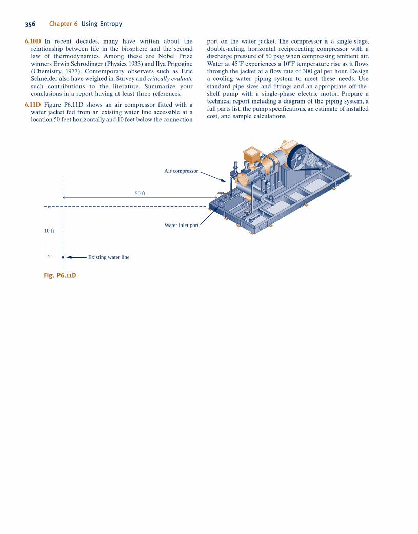
356 Chapter 6 Using Entropy
6.10D In recent decades, many have written about the
relationship between life in the biosphere and the second
law of thermodynamics. Among these are Nobel Prize
winners Erwin Schrodinger (Physics, 1933) and Ilya Prigogine
(Chemistry, 1977). Contemporary observers such as Eric
Schneider also have weighed in. Survey and critically evaluate such contributions to the literature. Summarize your
conclusions in a report having at least three references.
6.11D Figure P6.11D shows an air compressor fitted with a
water jacket fed from an existing water line accessible at a
location 50 feet horizontally and 10 feet below the connection
Fig. P6.11D
10 ft
Existing water line
Air compressor
50 ft
Water inlet port
port on the water jacket. The compressor is a single-stage,
double-acting, horizontal reciprocating compressor with a
discharge pressure of 50 psig when compressing ambient air.
Water at 458F experiences a 108F temperature rise as it flows
through the jacket at a flow rate of 300 gal per hour. Design
a cooling water piping system to meet these needs. Use
standard pipe sizes and fittings and an appropriate off-the-
shelf pump with a single-phase electric motor. Prepare a
technical report including a diagram of the piping system, a
full parts list, the pump specifications, an estimate of installed
cost, and sample calculations.
c06UsingEntropy.indd Page 356 5/26/10 3:30:41 PM user-s146 c06UsingEntropy.indd Page 356 5/26/10 3:30:41 PM user-s146 /Users/user-s146/Desktop/Merry_X-Mas/New/Users/user-s146/Desktop/Merry_X-Mas/New