Embed Size (px)
Citation preview

CONTACT 2000
Auf
lage
1.2
000
CONTACT 2000
CONTACT
CONNECTORS
CONTACT
CONNECTORS

3
InhaltsverzeichnisList of contentsSommaire
Einleitung / Introduction / Introduction 4
Technisches Vorwort / Technical considerations /Préambule technique 10
Rechtecksteckverbinder / Rectangular connector /Connecteur rectangulaireEinsätze / Inserts /Inserts
1.1 EPIC H-A 47
1.2 EPIC STA 53
1.3 EPIC H-BE 57
1.4 EPIC H-BS 67
1.5 EPIC H-BVE 71
1.6 EPIC H-D 75
1.7 EPIC H-DD 81
1.8 EPIC MC 85
1.9 EPIC TB 95
Kontakte und Werkzeuge / Contacts and Tools /Contacts et Outillage
2.1 EPIC CONTOOL 109
Gehäuse / Housings /Boîtiers
3.1 EPIC DA-VINCI H-A 133
Tüllengehäuse / Hood / Capot 135
Anbaugehäuse / Panel mount base / Embase encastrée 140
Sockelgehäuse / Surface mount base / Embase en saillie 143
Kupplungsgehäuse / Cable connector hood / Capot prolongateur 149
3.2 EPIC DA-VINCI H-B 153
Tüllengehäuse / Hood / Capot 155
Anbaugehäuse / Panel mount base / Embase encastrée 167
Sockelgehäuse / Surface mount base / Embase en saillie 171
Kupplungsgehäuse / Cable connector hood / Capot prolongateur 187
3.3 EPIC Eco H-B, ECO-Set/ECO H-B 6-24 Ag, ECO H-B 6-24 Tg 191
Kabelverschraubungen / Cable glands /Presse-étoupes4.1 EPIC CERTOSA 197
Zubehör / Accessories /Accessoires5.1 EPIC DUCO 207
Schutzdeckel / Protective cover / Couvercle de protection
5.2 EPIC CODIX 211
Codierung / Coding / Codage
5.3 EPIC DA-VINCI Perfect 215
Bügel / Levers / Leviers
5.4 EPIC ELMAC 219
EMV-Schutz / EMC-Protection / Protection CEM
Rundsteckverbinder / Circular connectors /Connecteurs circulaires6.1 EPIC CIRCON LS 1 225
6.2 EPIC CIRCON R2.5 235
6.3 EPIC CIRCON PP1 245
6.4 EPIC CIRCON R3.0 249
Lichtwellenleiter: INTERBUS Anwendung / Fibre optics: INTERBUS application /Fibre optic: Système INTERBUS7.1 EPIC BUS 257
Allgemeine Verkaufs- und Lieferbedingungen / General conditions of sale and delivery /Conditions générales de vente et de livraison 262
Artikelübersicht / List of part numbers / Rappel de numéros de référence 268
Niederlassungen und Vertretungen weltweit / Branches and Agencies worldwideEtablissements et Représentants mondiaux 274

4
Herzlich willkommen in der Welt
der CONTACT Steckverbinder!
Ob Tüllengehäuse, Anbau, Sockel –
oder Kupplungsgehäuse mit Quer-
oder Längsbügel, Stift- oder Buch-
seneinsatz, Kontakte , Werkzeuge
oder Verschraubungen, bei CONTACT
finden Sie die richtige EPIC® Kombi-
nation für die verschiedensten An-
wendungsbereiche aus Maschinen-
bau, Automobilindustrie, Roboter-,
Elektro-, Prüf-, Meß-, Regel- und
Gerätetechnik.
Dieser Katalog, Ausgabe C 2000, ist
gültig ab April 1999. Mit Einführung
dieser Ausgabe werden alle bis-
herigen Katalogsysteme ungültig.
Für Schreib- bzw. Druckfehler über-
nimmt CONTACT keine Haftung.
Für alle Angebote, Bestellannahmen
und Lieferungen gelten ausschließ-
lich unsere in diesem Katalog ent-
haltenen allgemeinen Verkaufs- und
Lieferbedingungen.
Herzlich Willkommen in der Welt der CONTACT SteckverbinderA warm welcome to the world of CONTACT Connectors!Bienvenue dans le monde des connecteurs rectangulaires CONTACT !
A warm welcome to the world of
CONTACT Connectors!
Whether you need the hood to mate with
panel bases or surface mounting bases or
a coupler hood for cable to cable connec-
tion. Whether you prefer single or double
latching connectors, or chose to have the
male or female insert in the base or hood.
Whether you need screw or crimp termi-
nation, need tools or cable glands
CONTACT can supply you with the cor-
rect EPIC“ combination. CONTACT has
the widest range of products for applica-
tions including mechanical engineering,
automotive, robotics, electrical, control,
communication technology, test, instru-
mentation, closed loop control and equip-
ment technology.
This catalogue issue, C 2000, is applica-
ble with effect from April 1999. Upon
introduction of this issue, all previous ca-
talogue systems become invalid.
CONTACT accepts no liability for typo-
graphical or printing errors. The general
conditions of sale and supply contained
in our catalogue are exclusively applica-
ble to all quotations, acceptances of or-
ders and deliveries.
Bienvenue dans le monde des
connecteurs rectangulaires
CONTACT !
Capots à douille, embases à encast-
rer, en saillie ou prolongateur, inserts
mâles et femelles, contacts, outils ou
boulonnerie : chez CONTACT, vous
trouvez la combinaison EPIC® qu’il
vous faut, quel que soit votre secteur
d’activité : mécanique, automobile,
robotique, appareillage électrique,
automatismes, télécommunications,
test, mesure et contrôle.
Ce catalogue, édition C 2000, est en
vigueur à partir avril 1999. Il remplace
et annule tous les catalogues
antérieurs. CONTACT n’est pas res-
ponsable des erreurs de composition
et d’impression. Pour toutes les
offres, acceptations de commande et
livraisons, seules sont valables nos
conditions générales de vente et de
livraison contenues dans le présent
catalogue.

5
Unter diesem Motto starten wir in
das neue Jahrtausend und werden
im Bereich der schweren Steckver-
binder Technologieführer mit welt-
weiter Präsenz. Auch in der LAPP
GRUPPE spielen wir eine wesentliche
Rolle. Dabei nutzen wir sinnvoll die
Synergieeffekte, die sich in einer der
führenden Firmengruppen auf dem
Kabel- und Leitungsmarkt ergeben.
Mit hoher Qualität und Innovations-
kraft erfüllen wir Ihre Anforderungen
in den Bereichen Elektro- und Ge-
rätetechnik sowie im Maschinenbau.
Egal ob Sie eines unserer elektrisch-
en Bauelemente oder unsere mehr-
poligen Steckverbinder benötigen,
die Verbindungen, die wir für Ihre
Anlagen aufbauen, sind so gut wie
die Kontakte, die wir zu unseren
Geschäftspartnern halten. Gehen
auch Sie mit uns die Erfolgspartner-
schaft ein. Wir entwickeln individuelle
Lösungen für Sie und bieten eine
breite Palette an bewährten Produk-
ten in der Steckverbindertechnologie.
In jedem Betriebsbereich fördern wir
die Eigenverantwortung unserer kom-
petenten Mitarbeiter. Eine schlanke
Hierarchie und kooperativer Team-
geist optimieren die Zusammenarbeit
von weltweit über 200 Mitarbeitern.
So schaffen wir ein einzigartiges Un-
ternehmen und erfüllen unseren
Leitspruch mit Leben. Sie als Kunde
ziehen den vollen Nutzen daraus.
Denn Ihre Zufriedenheit ist auf Dauer
der beste Gewinn.
CONTACT’s mission statement for
the New Millennium is: To achieve a
world-wide presence and become
leaders in the field of industrial
connector technology. As a member
of the LAPP GROUP, we play an
essential role and are able to take
advantage of the synergistic effect
which are made possible through our
association with a leading group of
companies in the cable technology
sector. In the areas of instrumen-
tation technology, electrical and
mechanical engineering, we meet
your demands with high quality and
innovative strength. The associations
that we have with our customers and
business partners are lasting ones. If
you enter into a partnership of
success with us, we will develop
individual solutions to meet your
needs and offer a broad range of
proven products in the field of
connector technology. In all areas of
our company we encourage and
support self-initiative and responsi-
bility for every employee. A decentral-
ised organisational structure coupled
with a cooperative team spirit helps
to optimise and support the co-
operation between more than 200
employees worldwide. This is how we
will fulfil our motto and become a
unique organisation. You as a
customer will receive the benefits and
in the long run, your satisfaction is
our best profit.
C’est avec ce mot d’ordre que nous
désirons attaquer le 2e millénaire et
être présent au niveau mondial en
tant que leader technologique dans
le domaine de la connectique indus-
trielle. Dans le GROUPE LAPP, nous
avons notre rôle à jouer, c’est pour-
quoi nous profitons de l’effet de
synergie crée par l’un des groupes
leader sur le marché du cable. Avec
une haute qualité et une force nova-
trice nous réalisons vos besoins
dans les secteurs tels que l’électro-
technique et la machine outil. Notre
souci est la liaison, peu importe que
cela soit avec un composant élec-
trique ou un connecteur multi pôles,
n’hésitez pas à vous joindre à nous
dans cette association constructive.
Nous développons des solutions
individualisées et vous soumettons
dans la technologie de la connec-
tique une large palette de produits
de valeur. Une hierarchie élancée et
une équipe géniale, coopérative con-
stituée de plus de 200 personnes
optimisent notre travail commun.
C’est ainsi que nous construisons
une entreprise unique et vivons
notre devise pleinement. Vous les
clients en tirerons le plus grand
profit, car votre satisfaction est, à
longue échéance notre plus belle
réussite.
Agieren statt reagierenAction not ReactionAgir au lieu de Réagir
Bernd Rath
- Geschäftsleitung -- Managing director -
- Direction -

1 Menschlichkeit1 Cooperation1 Rapport Humain
Das partnerschaftliche Verhältnis unserer Mitarbeiter stärkt das gegenseitige Vertrauen, fördert Eigenverantwortung und Teamarbeit.Kreative und begeisterte Mitarbeiter sind unserwertvollstes Kapital.
A partnership of cooperation among ouremployees strengthens mutual trust, encourag-ing and supporting initiative, responsibility and teamwork. Creative and enthusiasticemployees are our most valuable capital.
L’engagement de nos partenaires renforce laconfiance mutuelle, encourage le sens de laresponsabilité personnelle et le travail en équipe. La créativité et l’enthousiasme de noseffectifs est notre meilleur capital.
2 Neues Entdecken2 Innovations2 Découverte
Neue Ideen führen zu neuen Technologien.Computergestützte Entwicklungen führen zu innovativen Produkten. Unsere Mitarbeiterengagieren sich, damit die Verbindung zuIhnen stimmt.
New ideas lead to new technologies.Computerassisted developments lead to innovative products. Total commitment from all of our employees to ensures customersatisfaction.
De nouvelles idées nous mèment à de nouvelles technologies. Le développement del’outil informatique aboutit à l’innovation. Nospartenaires misent tout sur CONTACT, afin que notre relation soit la meilleure.
3 Wertigkeit3 Value3 Valeur
Qualität, Zuverlässigkeit, Sicherheit und Präzi-sion spiegeln sich wider in unseren Produkten.
Our products reflect quality, reliability and safety.
Qualité, confiance, sécurité et précision sont en étroite liaison avec nos produits.
8 Gründe CONTACT zu kontakten8 Reasons to ”contact” CONTACT8 Raisons de contacter CONTACT
6

4 Produkte4 Products4 Produits
Die EPIC® Baureihen umfassen mehr als 4000 Artikel, kundenspezifische Produkte und Werkzeuge für jede Anwendung. Wir entwickeln speziell nach Ihren Anforderun-gen und Wünschen.
The EPIC® ranges include more than 4000 items, custom-made types and tools tocover every eventuality, if you have a specialproduct need we will design it for you.
Nous avons plus de 4000 articles à disposition et restons persuadés que, dans notre gamme EPIC®, outillage et produits spéciaux vous y trouverez votre bonheur si tel n’était pas le cas nous nous lancerions dans une fabrication spéciale.
8 Beständigkeit8 Consistency8 Stabilité
Diese Verbindung besteht seit mehr als 30 Jahren – bis heute. Ein ersterCONTACTführt zu einer dauerhaftfunktionierenden Verbindung.
Established for over thirty years, oneinitial contact results in a lifelong andsound connection.
Cela fait plus de 30 ans que nousavons établi la liaison avec vous. Unpremier CONTACT assure une réelle,sincère et longue cooperation.
6 Zertifikate6 Certifications6 Certifications
Unser Engagement und unsere Verantwortungfür die Zukunft spiegelt sich in den Zertifikatenwider. Denn den CONTACT zu unseren Prinzi-pien werden wir nicht verlieren.
The certifications confirm our commitment andour responsibility for the future. We will notlose sight of our founding principles.
Cette certification confirme notre engagementet notre responsabilité pour l’avenir. Car nousne désirons pas perdre notre savoir faire.
5 Service5 Service5 Service
Wir halten die Verbindung zu Ihnen. Unserweltweites Vertriebs- und Servicenetz ist mitRat und Tat immer in Ihrer Nähe. Sie erhaltenAuskunft und Support vor Ort.
We keep in close touch with you. Our world-wide sales and service network is always inyour proximity, committed to providing youwith advice, assistance and support.
Nous gardons le CONTACT, n’hésitez pas ànous questionner. Notre service mondial esttoujours à votre service, vous obtiendrezfacilement soutien et renseignements.
7 Mitglied der LAPP GRUPPE7 Member of the LAPP GROUP7 Membre de GROUPE LAPP
Verbindungen schaffen von der Gegenwart indie Zukunft. Profitieren Sie von der langjährigenErfahrung einer starken Gruppe.
Create connections from the present to thefuture. Gain by the many years’ experience ofa powerful group.
Nouer des relations pour passer du présent àl’avenir. Profitons d’année d’expérience d’ungrand groupe. 7

8
Mehr als 1700 Mitarbei-ter in 32 Einzelfirmenund 50 Vertretungen aufallen fünf Kontinentenmachen die LAPPGRUPPE zum führendenAnbieter von Kabeln,Leitungen, Steckverbin-
dungen und Kommuni-kationstechnik. Diehochwertigen und zuver-lässigen Produktreihensind unter den Marken-namen Ölflex, Unitronic,Skintop, Hitronic undFleximark bekannt.
CONTACT GmbH mitStammsitz in Stuttgart-Vaihingen entwickelt,produziert und vertreibtunter dem Namen EPIC®
elektrische Bauelemente,insbesondere mehrpoligeSteckverbinder für dieElektro- und Nachrich-tentechnik, Prüf-, Meß-und Regeltechnik sowieMaschinenbau- undGerätetechnik. Mehr als150 Mitarbeiter bietenseit 1966 weltweitLösungen für kunden-spezifische Applikationenund gestalten zukunfts-weisende Innovationenauf dem Markt der Steck-verbindertechnologie.
CONTACT WeltweitCONTACT WorldwideCONTACT Mondiaux
The Group has 1700emplloyees and 30 com-panies world-wide, to-gether with distributorsin all continents. TheLAPP GROUP is a mar-ket leader for cable, harn-essing and associatedsystems. The productsare sold under the brandnames of Olflex, Uni-tronic, Skintop, Hitronicand Fleximark.
Plus de 1700 effectifsdans 30 sociétés et 50distributeurs sur cinqcontinents représententet poussent le GROUPELAPP sur la voie depremier dépositaire decables, de connecteurset de techniques decommunication. Les lig-nes de produits hautesen qualité et en perfor-mances sont commer-cialisées sous les nomsde: Olflex, Unitronic,Skintop, Hitronic etFleximark.
CONTACT GmbH hasbeen located in Stuttgart-Vaihingen since 1966.The electrical connec-tors are sold under thebrand name EPIC ® andare frequently used inmanufacturing, machin-ery, power supplies,cabinets and other sig-nal and control applica-tions. CONTACT has150 employees in Stutt-gart handling a Globalmarket, all of these people are dedicated toimproving connectortechnology throughoutthe market place.
CONTACT GmbH estinstallée à Stuttgart-Vaihingen; elle dévelop-pe, produit et distribuesous le nom EPIC® descomposants électriques,tout spécialement desconnecteurs multi pôlespour les secteurs del’électrotechnique, de lamachine outil et de latechnologie de précision.Plus de 150 effectifsproposent, depuis 1966au niveau mondial, dessolutions et des applica-tions a des demandesspécifiques, pour innoverla technologie du mar-ché de la connectique.
LAPP GROUP
CONTACT Deutschland

9
Ein 25-köpfiges ver-kaufs- und marketing-orientiertes Team bautseit 1985 die Marktfüh-rerschaft im Bereich derschweren Steckverbin-der aus. Mit Serviceleis-tungen, kundenspezifi-schen Konfektionierun-gen und einem flächen-deckenden Distributo-rennetz ist CONTACT
auf den britischen Inseln vertreten.
Auf dem „interconnec-tion and assembly“ -Markt in den USA, Ka-nada und Mexico bietetCONTACT USA ein aus-gefeiltes Produktpro-gramm an. Kundenspe-zifische Lösungen,neueProduktserien und Ka-belkonfektionierungenrunden das Programmab. CONTACT USAbetreut seine Kundenerstklassig mit einemDistributorennetz undeinem Auslieferungs-lager, das alle Anforde-rungen des amerikani-schen Marktes erfüllt.
Servicing the US,Canada and Mexico,CONTACT Electronicsoffer a comprehensiverange of connectorsand accessories, includ-ing a cable harnessingservice throughoutthecontinent. From it’swarehouse and throughan extensive nationalnetwork of representa-tion, a first class servicewith short turn roundtimes is available.
Par le biais du Marché„interconnection andassembly“ aux USA, leCanada et le Mexique, CONTACT aux EtatsUnis représente lagamme complète denos produits. Des réali-sations spécifiques pourcertains clients, les nou-
veaux produits, la con-fection de cables spé-ciaux complètent agréa-blement la gamme.CONTACT USA fidélisesa clientèle avec unstock important à dis-position et un sérieuxréseau de distributionsolidement implanté.
In Forbach betreibenunsere Mitarbeiter seit1990 ein umfangreichesWarenlager für kurzfri-stige Auslieferung derkompletten EPIC ® Pro-duktpalette. In jeder fran-zösischen Wirtschafts-region werden Interes-senten und Kundenindividuell und kompe-tent durch geschulteAußendienstmitarbeiterbetreut. Impulse fürProduktentwicklungenwerden an das Stamm-haus weitergeleitet.
Our sales office hasbeen based in Forbachsince 1990, and ourexperienced staff ope-rate a speedy deliveryservice from this depot.All regions of France are covered by highlytrained technical salespersonnel. Customers’special needs are trans-mitted to our engineer-ing group at our factoryin Stuttgart.
A Forbach nos collèguesont développé une airede stockage avec unegamme complète desproduits EPIC ® afin desatisfaire des livraisonsrapides. La France estdécoupée en plusieursrégions et est représen-tée par 9 agents quifont la promotion de nosproduits à la recherchede nouveaux marchés.
Formed in 1985, wehave a dedicated teamof 25 people in ourLondon operation. Weare the market leaderfor industrial connectorsand accessories used inhostile environments.Theoperation has focusedon delivering a high levelof service and offers aninnovative variety of solu-tions to the customer including all their har-nessing needs.
Un groupe de 25 per-sonnes commerciaux etspécialistes en marke-ting poussent depuis1985 la société sur lavoie de leader dans ledomaine de la connec-
tique. CONTACT est apprécié sur l’ile pour,son service, sa confec-tion de produits spécifi-ques sur demande etson solide réseau dedistributeurs.
CONTACT UK
CONTACT France
CONTACT USA

21
The most important considerations for a heavy duty connector are its electrical characteristics, its mechanical characteristics and
the materials from which it is manufactured. The heavy duty connector provides safe connection and disconnection of electrical
power or signals within robust housings which are suitable for hostile environments. (connectors should never be mated or unma-
ted under load)
The construction of a rectangular connector can be selected specificaly for a customer‘s requirement. EPIC“ industrial connec-
tors from Contact are made up of various components (housings and contact inserts).
The various components of the heavy duty rectangular connector are purchased individually and made up on a modular principle.
A wide range of housing sizes and many options of inserts and contacts make it possible to design the ideal connector for each
application.
The following individual components have to be purchased in order to produce the complete rectangular connector:
1. Cable Gland:
The Cable Gland provides a seal between the cable and the
connector housing. It may also be used to offer additional functions
like strain relief and and braid continuity for EMC protection.
2. Hood:
The connector housing for the cable entry.
3. Male insert:
Types of contact termination
• Screw
• Crimp(Stamped or machined)
• Cage clamp
4. Female insert:
Types of contact termination
• Screw
• Crimp (Stamped or Machined)
• Cage clamp
5. Base:
Panel mounting:
(cable entry though cut out in panel)
or
Surface mounting
(cable entry through a gland into the side of the connector base)
or
Cable Connector Hood:
cable to cable connection
Technical C O N S I D E R A T I O N STechnisches Vorwort / Technical Considerations/ Préambule technique

22
Housings:
Hood:
A hood may have a top or angle (side) entry of different PG sizes to
accommodate a wide range of cable diameters. The hood can be
mated with either a surface or panel mounting base, or a cable
coupler hood (for cable to cable connection).
Panel Base housing:
The panel base is wired from below though a hole cut in a panel.
The panel base is attached to the surface of a control panel for
connection of control or power cables.
Surface Base housing:
The surface base is a complete enclosure only offering cable entry
through a cable gland mounted either on one or both sides of the
base.
Cable Connector Hood:
The cable connector hood mates with a top entry hood to offer ca-
ble to cable connection. This is frequently used to extend cables.
locking lever (Latches) types:
There are two types of locking levers:
• Single locking lever (which bolts about the longer axis of the
connector)
• Double locking lever (which bolts about the shorter axis of the
connector)
The new Da-Vinci Perfect Series locking levers are removable and
can be mounted either on the hood or base as desired. This is valid
for
Double locking lever: H-B10/16/24, H-A32
Single locking lever: H-B 6
Panel cut out for panel mount base (mm)
Panel mount base A B C D E
H-A 3 30 —— 21 21 3,3
H-A 10 70 17,5 57,5 24 3,6
H-A 16 86 17,5 73,7 24 3,6
H-A 32 92 42 74,2 48,4 4,3
H-A 48 110 65 85,5 71 5,5
H-B 6 70 32 52,2 35 4,3
H-B 10 83 32 65,2 35 4,3
H-B 16 103 32 85,5 35 4,3
H-B 24 130 32 112,2 35 4,3
H-B 32 110 65 85,5 71 5,5
H-B 48 148 70 124 82 7
Technical C O N S I D E R A T I O N STechnisches Vorwort / Technical Considerations/ Préambule technique

23
Cable Gland:When the correct cable gland is selected to match the cable diameter a
good seal is ensured. Cable Glands are available to fulfill many additional
requirements. A gland with a saddle clamp supplies good strain relief or
one with a neoprene boot offers anti-kinking. These devices help to pre-
vent damage to the connection or the cable. In addition cable glands are
avialable for use with cables improving EMC performance by taking the
screen to the body of the connector.
Male and Female Inserts:
(NB: Information regarding materials is provided on the following pages)
The male and female inserts are the receptacles for the male and female
contacts respectively, and is the interface for the electrical connection. Ca-
ble is terminated to the contacts. Inserts provide the electrical insulation.
Contact types:
(NB: Information concerning materials/contact coatings is provided on the
following pages)
Screw termination:
This simple type of termination is distinguished by its ease of maintenan-
ce. No special tool is required, just a screwdriver to undo and to tighten up
the terminal screws.
Crimp termination:
The purpose of crimping is to produce a good mechanical, electrical and
gas-tight connection. This should remain unchanged with regard to quality
in the long-term, and should thus be reliable.
Crimping also reduces termination time and allows the designer to achieve
more connections than screw termination would permit in the same space
Hand-operated tools or crimping machines can be used to assemble
crimp contacts. The following points must be harmonised with each other
in order to obtain the ideal crimping result:
• Cross section dimension/gauge size and structure of the cable
• Contact type and size
• Tool and tool setting
There are two different contact types: - Machined and Stamped. These
two types of contact have differing characteristics in terms of quality and
how the termination is made.
Stamped contacts: The crimping sleeve allows a wider range of wire gua-
ges to be crimped. This guarantees reliable crimping quality. Furthermore,
the insertion and extraction force is usually lower with stamped pin and
socket contacts. This is achieved by the large contact area and the spring
characteristics of the stamped contact’s material. Stamped contacts can
be supplied on a bandolier for use with automatic feed crimping tools.
Machined contacts: With this popular type of contact, the suitable contact
size is matched to the wire gauge of the cable. The correct crimping tool
or die must be used.
Cage Clamp termination:
This type of termination is noted for its ease and speed of fitting without
an additional tool. The compensating effect of the cage clamp enables
good contact to be maintained in the long term.
Screw connection technology (as per DIN 0609)
Conductor section (mm2) 1 1,5 2,5 4 6 10
Screw thread: M 2,6 M 3 M 3 M 3,5 M 4 M 4
Test torque Nm: 40 50 50 80 120 120
Technical C O N S I D E R A T I O N STechnisches Vorwort / Technical Considerations/ Préambule technique

24
inserts
Housing H-A STA H-BE H-BS H-BVE H-D H-DD MC TB-H-BE TB-H-D
H-B 6 H-BE 6 H-DD 24 MC-R 6 TB-H-BE 6 TB-H-D 162 Modules
H-B 10 H-BE10 H-BVE 3 H-DD 42 MC-R 10 TB-H-BE 10 TB-H-D 243 Modules
H-B 16 H-BE 16 H-BS 6 H-BVE 6 H-D 40 H-DD 72 MC-R 16 TB-H-BE 16 TB-H-D 405 Modules
H-B 24 H-BE 24 H-BVE 10 H-D 64 H-DD 108 MC-R 24 TB-H-BE 24 TB-H-D 647 Modules
H-B 32 H-BE 32 H-BS 12 H-D 80 H-DD 144 MC-R 2x16 2 x10 Modules TB-H-D 40
H-B 48 H-BE 48 H-D 128 H-DD 216 MC-R 2x24 2 x14 Modules TB-H-D 64
H-A 3 H-A 3/4 STA 6 H-D 7/8
H-A 10 H-A 10 STA 14 H-D 15
H-A 16 H-A 16 STA 20 H-D 25
H-A 32 H-A 32 2 x H-D 50STA 20
H-A 48 H-A 48
Design series Voltageas per UL CSA SEVVDE 0110
Voltage Current Voltage Current Voltage Current Voltage CurrentV (AC) A V (AC) A V (AC) A V (AC) A
EPIC® H-A3/4 250 10 600 10 600 10-16 250 1010-48 250 16 600 14 600 20 250 10EPIC® STA6-20 60 10 48 10 48 10EPIC® H-BE6-48 400 16 600 16 600 10 400 16EPIC® Cage clamp6-48 500 16 600 16 600 16EPIC® H-BS6-12 400 35 440 35 600 35 400 35EPIC® H-BVE3-10 600 16 600 16 600 16 600 16EPIC® H-D7/8 42 / 250 10 250 10 250 1015-128 250 10 250 10 250 10EPIC® H-DD24-216 250 10 600 8,5 600 20 250 10EPIC® MC3-pin module 630 40 600 40 600 35 630 405-pin module 400 20 400 20 400 16 400 2010-pin module 250 10 250 10 240 10 250 1020-pin module 63 5 63 5 60 5 63 5HE module 630 25Coaxial moduleHigh voltage module 1000 16High voltage module 1000 50Cage clamp module 400 16Blank moduleEPIC® TB-H-BE6-24 380 16 600 16 600 16 250 10EPIC® TB-H-D16-64 250 10 600 7 600 10 250 10
UL, CSA under preparation
Housing sizes / inserts:
Technical data:
Technical C O N S I D E R A T I O N STechnisches Vorwort / Technical Considerations/ Préambule technique

25
Contact Material Details :
The coating of the base material with a precious metalis necessary to guarantee a long lasting and goodconnection. The contacts are plated normally by gal-vanic processes. To reach a long-lasting plating, thereare some requirements for the contact and the platingmaterial
Requirements on contact material:• Good dimensional stability• High corrosion resistance• Good electrical conductivity
Brass (copper zinc alloy) is used for it’s good mecha-nical properties and it’s electrical conductivity. Becau-se it is also relatively economical it has become one ofthe most preferred contact materials
Requirements on contact coatings:• High abrasion resistance• High hardness• Low contact resistance• High corrosion resistance• Low porosity• Good coat formation • Solderability
Silver or gold are the normal choice for surface coa-ting.
• Silver possesses the highest electrical conductivityof any metal and is the most cost-effective pre-cious metal. With sulphur or sulphurous productsin the ambient air, a brownish to black oxide coa-ting made up of silver sulphide (Ag2S) will rapidlybe formed. However, this coating will break up inthe process of mating and will be broken down byhigh currents, so that the necessary electrical con-ductivity is maintained. Passivation of the silversurface will delay the formation of the oxide coa-ting and will reduce the mating and unmating for-ces.
• Gold is the most tarnish resistant precious metal.Formation of oxides and sulphides can be dis-counted. Gold contacts are distinguished by theirlow mating and unmating forces. They are mainlyused for transmission of signals with low currentand voltage values.
Alternative materials for surface coating:
• Nickel is normally applied as a corrosion protec-tion and blocking layer. Furthermore, the relativelyhigh hardness of the Ni coating has a positive ef-fect on wear characteristics.
• Tin or Tin/Lead is one of the most frequently em-ployed metals for contacts, especially in the auto-motive field. As an aid to soldering, virtually allpartially coated strips in the connection area arecoated with tin or Tin/Lead. Due to the lowhardness of tin, the mating forces are very highand this makes it unsuitable for connectors thatare designed for a high number of mating cycles.
Base materialbrass
Liningnickel
Coating materialsilver or gold
Passivation for silvere.g. Thiol-based or by application of a thin coatof rhodium or chromatting
Technical C O N S I D E R A T I O N STechnisches Vorwort / Technical Considerations/ Préambule technique

26
Terms / glossary
Connectors:
Connectors are a generic device for providing an electrical in-
terface between electrical equipment and/or a power source.
Our connectors may not be mated or unmated under load.
Mating cycles:
Mating cycles are the number of insertion and extraction cy-
cles a connector can withstand before electrical or mechani-
cal failure in relationship to the connector’s design specifica-
tion.
Upper limit temperature:
The upper limit temperature is the maximum permissible
temperature, at which a Heavy Duty connector can still be
operated, due to heating up of the contacts by the ambient
temperature or other environmental conditions.
Lower limit temperature:
The lower limit temperature is the minimum permissible tem-
perature at which a Heavy Duty connector can still be opera-
ted.
Air Gap
The minimum gap of air between two conducting surfaces
permissable at given voltages.
Creep distance:
The minimum dimension along the surface of an insulating
material between two conducting surfaces.
Rated voltage:
The rated voltage is the voltage according to which the
connectors are designed and related to the relevant opera-
ting characteristics.
Rated current:
The rated current is the current at which a connector can
continuously (not intermittently) conduct through all contacts
simultaneously without exceeding the upper limit tempera-
ture.
Test voltage:
The test voltage is the maximum voltage at which a connec-
tor will not be subjected to flashover under the set conditi-
ons.
Technical C O N S I D E R A T I O N STechnisches Vorwort / Technical Considerations/ Préambule technique

27
Pollution:
Numerical value which states the anticipated pollution in the
micro-environment.
Pollution level 1:
No pollution or only dry, non-conductive pollution occurs.
This pollution has no influence.
e.g.: Open, unprotected insulations in air-conditioned or cle-
an dry rooms.
Pollution level 2:
Only non-conductive pollution occurs. Occasionally, howe-
ver, it may be anticipated that transient conductivity arises
due to condensation.
e.g.: Open unprotected insulations in residential, commercial
or business premises (fine mechanical engineering works-
hops, laboratories, test areas, rooms used for medical pur-
poses).
Pollution level 3:
Conductive pollution arises, or dry, non-conductive pollution
which becomes conductive because condensation has to be
anticipated.
e.g.: Open unprotected insulations in rooms of industrial,
commercial and agricultural companies, unheated storage
rooms, boilerhouses and workshops
Pollution level 4:
Contaimination leads to continuous conductivity caused by
condensation or other environmental contaminants.
e.g.: External exposed installations subject to all envi-
ronmental changes.
Pollution level 3 is typical for an industrial environment,
whilst pollution level 2 is typical for households.
Insulation materials:
Insulation materials are categorised into 4 groups according
to the CTI values.(Comparative Tracking Index)
Insulation material group I 600 ≤ CTI
Insulation material group II 400 ≤ CTI < 600
Insulation material group IIIa 175 ≤ CTI < 400
Insulation material group IIIb 100 ≤ CTI < 175
Comparative Tracking Index
The test for determination of the comparative index of
tracking (CTI or comparative tracking index ) as per IEC 112
provides a comparison of the characteristics of various insu-
lating materials under test conditions. By dripping an
aqueous solution onto a horizontal surface the electrolytic
conduction can be measured. This produces a qualitative
result. When the insulating material is introduced to the
tracking a quantitative comparison can be measured, i.e. the
comparative tracking index.
Switch contact:
If the construction of the circuit requires that for safety reaso-
ns, e.g. for neutral conductors, one or several contacts of a
connector have to make contact first upon mating, or have to
be separated last upon unmating, then connectors with
switch (extended) contacts are used.
EMC (elecromagnetic compatibility):
The capacity of an electrical installation to function satisfac-
torily in its electromagnetic environment without an unaccep-
table influence to the environment which also includes other
installations (DIN/VDE 0870, Section 1)
Coding:
Coding is a system by which it is possible to prevent interfa-
cing confusion between adjacent connectors which are of
the same configuration. This is useful if two or more connec-
tors of the same type are mounted on the same unit.
Polarisation:
Polarisation is a method used on connectors which prevents
incorrect mating of male and female inserts eg: pin1 to pin1.
Technical C O N S I D E R A T I O N STechnisches Vorwort / Technical Considerations/ Préambule technique

28
IP mode of protection:
IP - “insulation Protection” is a measure of protection against water and partical ingression that a device will withstand. The level
of protection offered by a device is laid down in the manufacturer’s specification according to DIN 40 050.
The first digit of the code states the level of protection against partical ingression and the second digit states the level of protec-
tion against penetration of water.
Modes of protection as per DIN 40050
Degrees of protection against solid foreign bodies
First
Code
0 No particular protection
1 Protection against penetration of solid foreign bodies
whose Diameter exceeds 50 mm
(large foreign bodies) 1)
No protection against intentional access
e.g. by hand, but exclusion of larger parts of the body
2 Protection against penetration of solid foreign bodies
whose diameter exceeds 12 mm
(medium-sized foreign bodies)1)
to exclude fingers or similar parts
3 Protection against penetration of solid foreign bodies
whose diameter exceeds 2.5 mm
(small foreign bodies)1) 2)
to exclude tools, wires or similar items whose thickness
exceeds 2.5 mm
4 Protection against penetration of solid foreign bodies
whose diameter exceeds 1 mm
(granular foreign body) 1) 2)
To exclude tools, wires, or similar items whose thickness
exceeds 1 mm
5 Protection against harmful accumulations of dust. Pene-
tration of dust is not entirely preventive; but dust must
not penetrate in such quantities that the mode of operati-
on of the equipment unit is affected (dust protection) 3)
Complete contact prevention
6 Prevention of penetration of dust (dust proof)
Complete contact prevention
1) In the case of operating media of protection levels 1 to 4,
consistently or inconsistently formed foreign bodies with
three dimensions perpendicular to each other and larger
than the corresponding diameter numerical values are
prevented from entering.
2) For degrees of pollution 3 and 4, the application of this
table is appropriate for operating media with drain holes
or cooling air apertures which are the subject of the res-
ponsibility of the corresponding expert committee.3) For protection level 5, the application of this table is ap-
propriate for operating media with drain holes, and co-
mes under the responsibility of the respective expert
committee.
Degrees of protection against water
Second
Code
0 No particular protection
1 Protection against water dropping perpendicularly.
No harmful effect must arise (water drip)
2 Protection against water dropping perpendicularly.
No harmful effect must arise with an equipment unit
15° in relation to its normal position (casing) (obliquely
water drip)
3 Protection against water dropping at any angle of up 60°
to the perpendicular. No harmful effect must arise (water
spray)
4 Protection against water which splashes onto the equip-
ment unit (e.g. casing) from any direction. No harmful ef-
fect must arise (water splash)
5 Protection against water steam from a jet which is direc-
ted against the equipment unit (casing) from any direc-
tion. No harmful effects must arise (water spray)
6 Protection against heavy sea or powerful water jet. Water
must not penetrate the operating equipment in harmful
quantities (flooding)
7 Protection against water if the operating equipment is
dipped in water under certain pressure and time Water
must not penetrate in harmful quantities (dipping)
8 The operating media (casing) is suitable for permanent
dipping in water under conditions which are to be defi-
ned by the manufacturer (immersion). 1)
1) This level of protection normally relates to an air-tight
field operating medium.
For certain operating media, however, water may pene-
trate provided that there is no harmful effect
Technical C O N S I D E R A T I O N STechnisches Vorwort / Technical Considerations/ Préambule technique
29
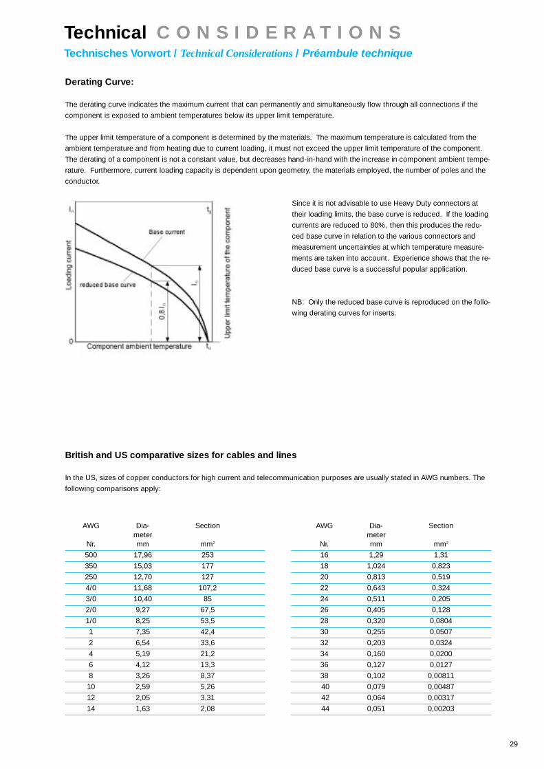
Derating Curve:
The derating curve indicates the maximum current that can permanently and simultaneously flow through all connections if the
component is exposed to ambient temperatures below its upper limit temperature.
The upper limit temperature of a component is determined by the materials. The maximum temperature is calculated from the
ambient temperature and from heating due to current loading, it must not exceed the upper limit temperature of the component.
The derating of a component is not a constant value, but decreases hand-in-hand with the increase in component ambient tempe-
rature. Furthermore, current loading capacity is dependent upon geometry, the materials employed, the number of poles and the
conductor.
Since it is not advisable to use Heavy Duty connectors at
their loading limits, the base curve is reduced. If the loading
currents are reduced to 80%, then this produces the redu-
ced base curve in relation to the various connectors and
measurement uncertainties at which temperature measure-
ments are taken into account. Experience shows that the re-
duced base curve is a successful popular application.
NB: Only the reduced base curve is reproduced on the follo-
wing derating curves for inserts.
British and US comparative sizes for cables and lines
In the US, sizes of copper conductors for high current and telecommunication purposes are usually stated in AWG numbers. The
following comparisons apply:
AWG Dia- Section AWG Dia- Sectionmeter meter
Nr. mm mm2 Nr. mm mm2
500 17,96 253 16 1,29 1,31
350 15,03 177 18 1,024 0,823
250 12,70 127 20 0,813 0,519
4/0 11,68 107,2 22 0,643 0,324
3/0 10,40 85 24 0,511 0,205
2/0 9,27 67,5 26 0,405 0,128
1/0 8,25 53,5 28 0,320 0,0804
1 7,35 42,4 30 0,255 0,0507
2 6,54 33,6 32 0,203 0,0324
4 5,19 21,2 34 0,160 0,0200
6 4,12 13,3 36 0,127 0,0127
8 3,26 8,37 38 0,102 0,00811
10 2,59 5,26 40 0,079 0,00487
12 2,05 3,31 42 0,064 0,00317
14 1,63 2,08 44 0,051 0,00203
Technical C O N S I D E R A T I O N STechnisches Vorwort / Technical Considerations/ Préambule technique

30
Materials
PA (Polyamides)
Polyamides are high-impact, very tough thermoplastics
which exhibit very good electrical insulation characteristics,
favourable tracking characteristics and resistance to flasho-
ver. The greater the proportion of filling agents, the less the
water absorption and the better the dimensional stability.
Their specific surface resistance, due to humidity absorption,
is somewhat less than for other plastics, but there is the ad-
vantage that this reduces the tendency for a build-up of elec-
trostatic charge and thus the tendency for PA components to
attract dust is avoided.
These characteristics mean that polyamides are suitable for
production of casings for electrical plant.
Typical application: Da-Vinci Perfect clip-on information tags,
high-voltage modules, plastic frame grips;
PC (Polycarbonate)
Polycarbonate is an amorphous thermoplastic. It is distin-
guished by high strength, viscosity, hardness, rigidity and
good resistance to heat & cold in relation to its form, and
good electrical characteristics. PC is a glass-clear, easily-
dyed plastic with very low water absorption, and exhibits
high dimensional precision, low wastage and good proces-
sability.
Typical application: Inserts/insulators, frames and individual
modules for the modular system.
PBT (Polybutylenterephthalate)
Polybutylenterephthalate is a thermoplastic polyester and is
distinguished by its high rigidity, high stability of form under
heat, low creep, low water absorption of <0,2%, high dimen-
sional stability and good to very good electrical characteri-
stics. It is a tough, viscous plastic with high abrasion resi-
stance, high dimensional stability and long-term strength
combined with good slip & wearing characteristics.
Typical application: inserts/insulators
Chemical resistance of plastics
Diluted acid PA 6 GF PA 66 GF PC GF PBT GF
Acetone + + + +
Aqqueous ammoniac + + +
Benzene + + + +
Benzol + + + +
Diesel oil + + +
Concentrated acetic acid + + + +
Alkaline potassium
Methanol +
Engine oil +
Diluted alkalis + + + +
Chlorhydrocarbons + + +
Outdoor exposure + +
Cold water/seawater + + +
+ = resistant; = conditionally resistant; = non-resistant
Electrical, thermal and mechanical valuesElectrical values
Unit PA 6 GF PA 66 GF PC GF PBT GF
Flashhover resistance ( DIN 53481; VDE 0303 ) Ed 1) kV/mm 80 /40 > 80 / 40 35 100
Tracking current resistance ( DIN 53480; VDE 0303 ) CTI > 500 > 500 > 125 bis 250 > 500
Thermal values
Temperature limit for short-term application ° C 180 200 165 190
Temperature limit for long-term application ° C 105 120 130 140
Mechanical values
Density ( DIN 53479 ) g / cm3 1,35 1,35 1,34 1,53
Modulus of elasticity in the flexional and tensile test Ez 1)
( DIN 53457 ) MPa 8500 / 6000 9700 / 7500 6000 10000
Absorption of humidity in NK until occurrence
of saturation
( DIN 5714 ) % 2,1 1,5 0,13 0,13
1) Numerical information relates to both dry & atmospherically humid conditions
Technical C O N S I D E R A T I O N STechnisches Vorwort / Technical Considerations/ Préambule technique

31
Dichtungswerkstoffe:
NBR (e.g. Perbunan)Synthetic rubber is used for parts with high resistance to fu-
els, oil, fat and aliphatic solvents at high temperatures. The
durability of the material can be varied by the compounds
used during manufacture, to protect against Ozone or the
prevailing environmental conditions.
O Rings are used in various applications, e.g. Electrical and
automotive industry, hydraulics, mechanical engineering , oil
industry for membrans, fuel hoses,seals, formed items, plate
gaskets etc.
Typical application: Seals and gaskets for rectangular
connectors and glands.
FPM (e.g. Viton)this fluoroelastomer is commonly used for rubber parts and
withstands fuel, oil, lubricants, many acids and chemicals
during extreme thermal stress. Viton has also good mechani-
cal qualities, flame resistance and high durabiltiy against
ozone and environmental impacts of every kind.
Typical application: Seal in circular connector type A and
glands.
Chemical, thermal and mechanical values
Abbreviation NBR FPM
Commercial name Perbunan N® Viton / Fluorel®
Hycar
Shore A hardness range at standard
solid quality toleranz = ± 5° Shore approx 25 bis 40 60 bis 90
Tear strength
N / mm2 bei +20°C to Approx 20 Approx 17
General weather-resistance good excellent
Ozone resistance satisfactory excellent
Resistance to oil excellent excellent
Resistance to fuel good excellent
Resistance to solvent partially good very good
General resistance to acids satisfactory very good
Temperature resistance:
a) Short-term: prox - 40° to + 150°C - 30° to + 280°C
b) Long-term: prox - 30° to + 120°C - 20° to + 230°C
Vapour resistance good satisfactory to good
Can be supplied in foodstuffs products yes no
Technical C O N S I D E R A T I O N STechnisches Vorwort / Technical Considerations/ Préambule technique

EPIC® RechtecksteckverbinderEPIC® Rectangular ConnectorsEPIC® Connecteur Rectangulaire
44

Qualität, Funktionalität und Prozeßsi-
cherheit. Drei Eigenschaften, ein Mar-
kenname: EPIC® Rechtecksteckver-
binder überzeugen durch innovative
und formvollendete Gehäuseformen mit
der einzigartigen Da-Vinci Perfect Bü-
gelgeneration.
Quality, functionality and safety are the
three key words that describe the
brand name EPIC®. These rectangular
industrial connectors are reowned for
their innovative electrical design and
physical characteristics. The unique
”Da-Vinci Perfect“ housings and levers
make them ideal for factory automation
applications.
Qualité, fiabilité, sécurité accrue, trois
critères et un nom : EPIC®, nous
persuadent pour ce Connecteur Rec-
tangulaire avec la forme novatrice de
son capot et ses leviers nouvelle
génération Da-Vinci Perfect.
Technische Daten / Technical Data / Caractéristiques techniques
Baureihe Kontaktzahlen Bemessungsspannung Bemessungsstrom AnschlußartSeries No. of contacts rated tension Rated current TerminationSérie N° de contacts Tension nominale Intensité nominale Raccordement
EPIC® H-A 3 - 48 VDE: 250 V VDE: 10/16 A schraubUL: 600 V UL: 10/14 A screwCSA: 600 V CSA: 10/16/20 A à visserSEV: 250 V SEV: 10 A
EPIC® STA 3 - 20 VDE: 60 V VDE: 10 A schraub, lötUL: 48 V UL: 10 A screw, solderCSA: 48 V CSA: 10 A à visser, à souderSEV: SEV:
EPIC® H-BE 6 - 48 VDE: 400 V VDE: 16 A schraub, crimpUL: 600 V UL: 16 A screw, crimpCSA: 600 V CSA: 10 A à visser, à sertirSEV: 400 V SEV: 16 A
VDE: 500 V VDE: 16 A Käfigzugfeder UL: 600 V UL 16 A cage clampCSA: 600 V CSA: 16 A lame de pression
EPIC® H-BS 6 - 12 VDE: 400 V VDE: 35 A schraubUL: 440 V UL: 35 A screw CSA: 600 V CSA: 35 A à visserSEV: 400 V SEV: 35 A
EPIC® H-BVE 3 - 10 VDE: 600 V VDE: 16 A schraubUL: 600 V UL: 16 A screwCSA: 600 V CSA: 16 A à visserSEV: 600 V SEV: 16 A
EPIC® H-D 7 - 128 VDE: 250 V VDE: 10 A crimpUL: 250 V UL: 10 A crimpCSA: CSA: à sertirSEV: 250 V SEV: 10 A
EPIC® H-DD 24 - 216 VDE: 250 V VDE: 10 A crimpUL: 600 V UL: 8,5 A crimp CSA: 600 V CSA: 20 A à sertirSEV: 250 V SEV: 10 A
EPIC® MC 3 - 280 VDE: 100-1000 V VDE: 5-40 A crimpUL: 63-630 V UL: 10-40 A crimpCSA: 63-630 V CSA: 5-40 A à sertirSEV: 63-630 V SEV: 5-40 A
EPIC® TB-H-BE 6 - 24 VDE: 380 V VDE: 16 A schraubUL: 600 V UL: 10/16 A screwCSA: 600 V CSA: 10/16 A à visserSEV: 380 V SEV: 10 A
EPIC® TB-H-D 16 - 64 VDE: 250 V VDE: 10 A schraubUL: 600 V UL: 7 A screwCSA: 600 V CSA: 10 A à visserSEV: 250 V SEV: 10 A
45

47
Überall dort, wo das Platzangebot begrenzt ist,
finden die „Kleinen“ H-A 3/4 ihren Einsatz. Die
bewährten EPIC“ H-A 10 - 48 Einsätze gibt es
jetzt mit kurzem PE – Anschluß. Bei bis zu 2,5
mm2 Anschlußquerschnitt, einzigartig. Evoluti-
on im Kleinen für Ihre Sicherheit.
The "small" H-A 3 / 4 inserts are used where-
ver space is limited. The proven EPIC“ H-A 10
- 48 inserts now have a shortened PE connec-
tion. Unique, because the wire cross-section
can still be up to 2.5 mm2. Evolution in minia-
ture for your safety.
Partout où la place est limitée, les "petits" ins-
erts H-A 3/4 trouvent leur domaine d'utilisati-
on. Les inserts EPIC“ H-A 10-48 sont mainten-
ant équipés d’une borne terre raccourcie. La
section du fil peut toujours être de 2.5 mm2
maxi. Une petite évolution technique.
1.1 EPIC® H - AEinsätze / Inserts/ Inserts

48
Technische Daten:• Kontaktzahlen: . . . . . . . . . . 3, 4, 10, 16, 32, 48 (+ PE)• Bemessungsspannung: . . . VDE: 250 V EPIC® H-A 3-48
UL: 250 V EPIC® H-A 3/4600 V EPIC® H-A 10-48
CSA: 600 V EPIC® H-A 3-48SEV: 400 V EPIC® H-A 3-48
• Bemessungsstrom: . . . . . . VDE: 10 A EPIC® H-A 3/416 A EPIC® H-A 10-48
UL: 10 A EPIC® H-A 3/414 A EPIC® H-A 10-48
CSA: 10/16 A EPIC® H-A 3/420 A EPIC® H-A 10-48
SEV: 16 A EPIC® H-A 3-48• Verschmutzungsgrad: . . . . 3• Prüfspannung: . . . . . . . . . . 4 kV• Leitungsanschluß: . . . . . . . Schraubanschluß: 0,5-2,5 mm2
• Temperaturbereich: . . . . . . -40°C - 125°C• Kontakte: . . . . . . . . . . . . . . Kupferlegierung, hartversilbert• Durchgangswiderstand: . . .1,5-4 mOhm
Technical Data:• Number of contacts: . . . . . . . . 3, 4, 10, 16, 32, 48 (+ PE)• Rated voltage: . . . . . . . . . . . . .VDE: 250 V EPIC® H-A 3-48
UL: 250 V EPIC® H-A 3/4600 V EPIC® H-A 10-48
CSA: 600 V EPIC® H-A 3-48SEV: 400 V EPIC® H-A 3-48
• Rated current: . . . . . . . . . . . . .VDE: 10 A EPIC® H-A 3/4 16 A EPIC® H-A 10-48
UL: 10 A EPIC® H-A 3/414 A EPIC® H-A 10-48
CSA: 10/16 A EPIC® H-A 3/420 A EPIC® H-A 10-48
SEV: 16 A EPIC® H-A 3-48• Pollution level: . . . . . . . . . . . . 3• Test voltage: . . . . . . . . . . . . . . 4 kV• Termination technique: . . . . . .Screw termination: 0,5-2,5 mm2
• Temperature range: . . . . . . . . -40°C - 125°C• Contacts: . . . . . . . . . . . . . . . . Copper alloy, silver plated• Contact resistance: . . . . . . . . 1,5-4 mOhm
Caractéristiques techniques:• Nombre de contacts: . . . . . 3, 4, 10, 16, 32, 48 (+ PE)• Tension nominale: . . . . . . . VDE: 250 V EPIC® H-A 3-48
UL: 250 V EPIC® H-A 3/4600 V EPIC® H-A 10-48
CSA: 600 V EPIC® H-A 3-48SEV: 400 V EPIC® H-A 3-48
• Courant nominale: . . . . . . . VDE: 10 A EPIC® H-A 3/4 16 A EPIC® H-A 10-48
UL: 10 A EPIC® H-A 3/414 A EPIC® H-A 10-48
CSA: 10/16 A EPIC® H-A 3/420 A EPIC® H-A 10-48
SEV: 16 A EPIC® H-A 3-48• Degré de pollution: . . . . . . 3• Tension d‘essai: . . . . . . . . . 4 kV• Raccordement: . . . . . . . . . Raccord à visser: 0,5-2,5 mm2
• Gamme de température: . . -40°C - 125°C• Contacts: . . . . . . . . . . . . . . Alliage cuivre, argenté• Résistance de passage: . . . 1,5-4 mOhm
1.1 EPIC® H - AEinsätze / Inserts/ Inserts
H-A 2,5 mm2
0
5
10
15
20
25
30
35
0 20 40 60 80 100 120 140
H-A 3,4
H-A 10
H-A 16
Bel
astu
ngss
trom
[ A
]W
orki
ng c
urre
nt [
A ]
Inte
nsité
de
serv
ice
[ A ]
Umgebungstemperatur [ ºC ]Ambient Temperature [ ºC ]Température ambiante [ ºC ]
H-A 1,5 mm2
0
5
10
15
20
25
0 20 40 60 80 100 120 140
H-A 10
H-A 3
H-A 16
H-A 4
Bel
astu
ngss
trom
[ A
]W
orki
ng c
urre
nt [
A ]
Inte
nsité
de
serv
ice
[ A ]
Umgebungstemperatur [ ºC ]Ambient Temperature [ ºC ]Température ambiante [ ºC ]

49
H-A 3
Artikel Version Art.Nr. Drahtschutz Kontakte L L1 Hpart version part No. wire protection contactsarticle version N° art. protection de fil contacts
H-A 3 SS Stift / male/ mâle 10420000* 3 21 23,3 26,3
H-A 3 BS Buchse / female/ femelle 10421000* 3 21 14,0 25,5
Gehäuse / Housings/ Boîtiers:3.1: H-A 3
H-A 4
Artikel Version Art.Nr. Drahtschutz Kontakte L L1 Hpart version part No. wire protection contactsarticle version N° art. protection de fil contacts
H-A 4 SS Stift / male/ mâle 10431000* 4 21 23,6 32,5
H-A 4 BS Buchse / female/ femelle 10432000* 4 21 16,7 31,8
Gehäuse / Housings/ Boîtiers:3.1: H-A 3
Ansicht anschlußseitigView from cable sideVue côte raccordement
Ansicht anschlußseitigView from cable sideVue côte raccordement
1.1 EPIC® H - AEinsätze / Inserts/ Inserts

50
H-A 10
Artikel Version Art.Nr. Drahtschutz Kontakte L L1 Apart version part No. wire protection contactsarticle version N° art. protection de fil contacts
H-A 10 SS Stift / male/ mâle 10440100* 10 56,5 49,5 42,5
H-A 10 BS Buchse / female/ femelle 10441100* 10 56,5 49,5 42,5
H-A 10 SS Stift / male/ mâle 10440000* 10 56,5 49,5 42,5
H-A 10 BS Buchse / female/ femelle 10441000* 10 56,5 49,5 42,5
Gehäuse / Housings/ Boîtiers:3.1: H-A 10
H-A 16
Artikel Version Art.Nr. Drahtschutz Kontakte L L1 Apart version part No. wire protection contactsarticle version N° art. protection de fil contacts
H-A 16 SS Stift / male/ mâle 10530000* 16 73 66 60
H-A 16 BS Buchse / female/ femelle 10531000* 16 73 66 60
H-A 16 SS Stift / male/ mâle 10532000* 16 73 66 60
H-A 16 BS Buchse / female/ femelle 10533000* 16 73 66 60
Gehäuse / Housings/ Boîtiers:3.1: H-A 16
Ansicht anschlußseitigView from cable sideVue côte raccordement
Ansicht anschlußseitigView from cable sideVue côte raccordement
MontageausschnittPanel cut-outDécoupe de montage
1.1 EPIC® H - AEinsätze / Inserts/ Inserts

51
H-A 32
Artikel Version Art.Nr. Drahtschutz Kontakte L L1 Apart version part No. wire protection contactsarticle version N° art. protection de fil contacts
H-A 16 SS 1-16 Stift / male/ mâle 10530000* 32 73 66 60H-A 16 SS 17-32 10540000* 73 66 60
H-A 16 BS 1-16 Buchse / female/ femelle 10531000* 32 73 66 60H-A 16 BS 17-32 10541000* 73 66 60
H-A 16 SS 1-16 Stift / male/ mâle 10532000* 32 73 66 60H-A 16 SS 17-32 10542000* 73 66 60
H-A 16 BS 1-16 Buchse / female/ femelle 10533000* 32 73 66 60H-A 16 BS 17-32 10543000* 73 66 60
Gehäuse / Housings/ Boîtiers:3.1: H-A 32
H-A 48
Artikel Version Art.Nr. Drahtschutz Kontakte L L1 Apart version part No. wire protection contactsarticle version N° art. protection de fil contacts
H-A 16 SS 1-16 Stift / male/ mâle 10530000* 48 73 66 60H-A 16 SS 17-32 10540000* 73 66 60H-A 16 SS 33-48 10540100 73 66 60
H-A 16 BS 1-16 Buchse / female/ femelle 10531000* 48 73 66 60H-A 16 BS 17-32 10541000* 73 66 60H-A 16 BS 33-48 10541100 73 66 60
H-A 16 SS 1-16 Stift / male/ mâle 10532000* 48 73 66 60H-A 16 SS 17-32 10542000* 73 66 60H-A 16 SS 33-48 10542100 73 66 60
H-A 16 BS 1-16 Buchse / female/ femelle 10533000* 48 73 66 60H-A 16 BS 17-32 10543000* 73 66 60H-A 16 BS 33-48 10543100 73 66 60
Gehäuse / Housings/ Boîtiers:3.1: H-A 48
Ansicht anschlußseitigView from cable sideVue côte raccordement
Ansicht anschlußseitigView from cable sideVue côte raccordement
MontageausschnittPanel cut-outDécoupe de montage
MontageausschnittPanel cut-outDécoupe de montage
1.1 EPIC® H - AEinsätze / Inserts/ Inserts

53
Der millionenfach bewährte Steckverbinder mit
den soliden Kontaktfedern findet im Geräte-
bau, in Steuerungsanlagen und Labors, sowie
in der Einschubtechnik große Verwendung. Die
Einsätze sind in Schraubanschluß- und Lötan-
schlußtechnik erhältlich.
The connectors proven in a million applicati-
ons with solid spring-designed contacts are
used extensively in the construction of devi-
ces, in control units, laboratories and with-
drawable-unit design.
Easy-mount inserts which are available with
screw and solder connection.
Le connecteur des millions de fois testé, aux
solides inserts à lamelles de contact, sont lar-
gement utilisés dans la construction d'ap-
pareils, dans les installations de contrôle, de
commande dans les laboratoires, ainsi que
dans les systèmes de tiroirs ou unités amo-
vibles. Des connecteurs faciles à monter, qui
sont disponibles en version à visser ou à sou-
der.
1.2 EPIC® S T AEinsätze / Inserts/ Inserts

54
Technische Daten:• Kontaktzahlen: 6, 14, 20• Bemessungsspannung: VDE: 60 V EPIC® STA 6-20
UL: 48 V EPIC® STA 6-20CSA: 48 V EPIC® STA 6-20
• Bemessungsstrom: VDE: 10 A EPIC® STA 6-20UL: 10 A EPIC® STA 6-20CSA: 10 A EPIC® STA 6-20
• Verschmutzungsgrad: 2• Prüfpannung: 1,5 kV• Leitungsanschluß: Lötanschluß: bis 1,5 mm2
Schraubanschluß: 0,5-1,5 mm2
• Temperaturbereich: -40°C - 80°C• Kontakte: Kupferlegierung, hartversilbert• Durchgangswiderstand: < 2 mOhm
Technical Data:• Number of contacts: . . . . . . . . 6, 14, 20• Rated voltage: . . . . . . . . . . . . . VDE: 60 V EPIC® STA 6-20
UL: 48 V EPIC® STA 6-20CSA: 48 V EPIC® STA 6-20
• Rated current: . . . . . . . . . . . . .VDE: 10 A EPIC® STA 6-20UL: 10 A EPIC® STA 6-20CSA: 10 A EPIC® STA 6-20
• Pollution level: . . . . . . . . . . . . 2• Test voltage: . . . . . . . . . . . . . . .1,5 kV• Termination technique:. . . . . . Solder termination: up to 1,5 mm2
Screw termination: 0,5-1,5 mm2
• Temperature range: . . . . . . . . . -40°C - 80°C• Contacts: . . . . . . . . . . . . . . . . . Copper alloy, silver plated•Contact resistance: . . . . . . . . . . < 2 mOhm
Caractéristiques techniques:• Nombre de contacts: . . . . . 6, 14, 20• Tension nominale: . . . . . . . . VDE: 60 V EPIC® STA 6-20
UL: 48 V EPIC® STA 6-20CSA: 48 V EPIC® STA 6-20
• Courant nominale: . . . . . . . .VDE: 10 A EPIC® STA 6-20UL: 10 A EPIC® STA 6-20CSA: 10 A EPIC® STA 6-20
• Degré de pollution: . . . . . . . 2• Tension d‘essai: . . . . . . . . . .1,5 kV• Raccordement: . . . . . . . . . . Raccord à souder: 1,5 mm2 maxi
Raccord à visser: 0,5-1,5 mm2
• Gamme de température: . . . . . -40°C - 80°C• Contacts: . . . . . . . . . . . . . . .Alliage cuivre, argenté• Résistance de passage: . . . < 2 mOhm
1.2 EPIC® S T AEinsätze / Inserts/ Inserts
STA 1,0 mm2
0
5
10
15
20
0 20 40 60 80 100
STA 14
STA 6
STA 20
Bel
astu
ngss
trom
[ A
]W
orki
ng c
urre
nt [
A ]
Inte
nsité
de
serv
ice
[ A ]
Umgebungstemperatur [ ºC ]Ambient Temperature [ ºC ]Température ambiante [ ºC ]

55
Schraubanschluß / Screw termination / Raccord à visser
STA 6
Artikel Version Art.Nr. Kontakte L L1 Apart version part No. contactsarticle version N° art. contacts
STA 6 FS Stift / male/ mâle 10488100* 6
STA 6 SS Buchse / female/ femelle 10486100* 6
Gehäuse / Housings/ Boîtiers:3.1: H-A 3
MontageausschnittPanel cut-outDécoupe de montage
STA 14
Artikel Version Art.Nr. Kontakte L L1 Apart version part No. contactsarticle version N° art. contacts
STA 14 FS Stift / male/ mâle 10493100* 14 56,5 49,5 41,5
STA 14 SS Buchse / female/ femelle 10491100* 14 56,5 49,5 41,5
Gehäuse / Housings/ Boîtiers:3.1: H-A 10
STA 20
Artikel Version Art.Nr. Kontakte L L1 Apart version part No. contactsarticle version N° art. contacts
STA 20 FS Stift / male/ mâle 10503100* 20 73 66 58
STA 20 SS Buchse / female/ femelle 10501100* 20 73 66 58
Gehäuse / Housings/ Boîtiers:3.1: H-A 16
Ansicht anschlußseitigView from cable sideVue côte raccordement
Ansicht anschlußseitigView from cable sideVue côte raccordement
Ansicht anschlußseitigView from cable sideVue côte raccordement
1.2 EPIC® S T AEinsätze / Inserts/ Inserts

56
Lötanschluß / Solder termination / Raccord à souder
STA 6
Artikel Version Art.Nr. Kontakte L L1 Apart version part No. contactsarticle version N° art. contacts
STA 6 FL Stift / male/ mâle 10487200* 6
STA 6 SL Buchse / female/ femelle 10485200* 6
Gehäuse / Housings/ Boîtiers:3.1: H-A 3
STA 14
Artikel Version Art.Nr. Kontakte L L1 Apart version part No. contactsarticle version N° art. contacts
STA 14 FL Stift / male/ mâle 10492200* 14 56,5 49,5 41,5
STA 14 SL Buchse / female/ femelle 10490200* 14 56,5 49,5 41,5
Gehäuse / Housings/ Boîtiers:3.1: H-A 10
STA 20
Artikel Version Art.Nr. Kontakte L L1 Apart version part No. contactsarticle version N° art. contacts
STA 20 FL Stift / male/ mâle 10502200* 20 73 66 58
STA 20 SL Buchse / female/ femelle 10500200* 20 73 66 58
Gehäuse / Housings/ Boîtiers:3.1: H-A 16
Ansicht anschlußseitigView from cable sideVue côte raccordement
Ansicht anschlußseitigView from cable sideVue côte raccordement
Ansicht anschlußseitigView from cable sideVue côte raccordement
1.2 EPIC® S T AEinsätze / Inserts/ Inserts
MontageausschnittPanel cut-outDécoupe de montage
57
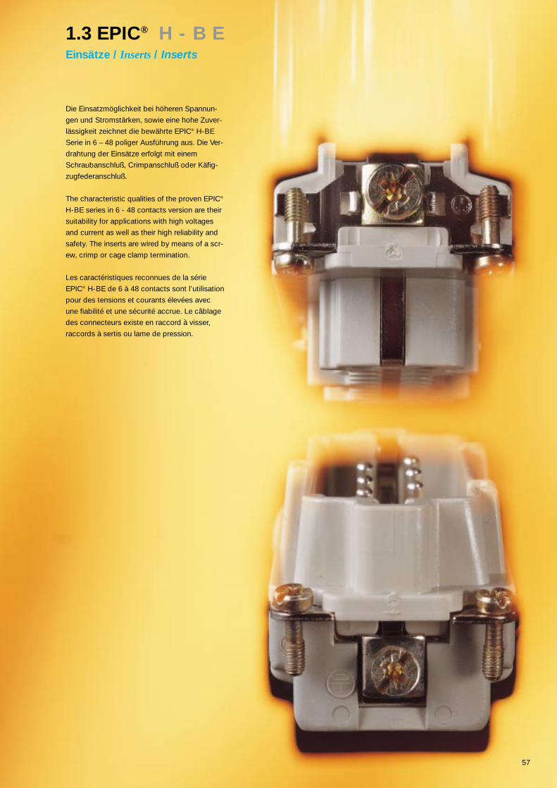
Die Einsatzmöglichkeit bei höheren Spannun-
gen und Stromstärken, sowie eine hohe Zuver-
lässigkeit zeichnet die bewährte EPIC® H-BE
Serie in 6 – 48 poliger Ausführung aus. Die Ver-
drahtung der Einsätze erfolgt mit einem
Schraubanschluß, Crimpanschluß oder Käfig-
zugfederanschluß.
The characteristic qualities of the proven EPIC®
H-BE series in 6 - 48 contacts version are their
suitability for applications with high voltages
and current as well as their high reliability and
safety. The inserts are wired by means of a scr-
ew, crimp or cage clamp termination.
Les caractéristiques reconnues de la série
EPIC® H-BE de 6 à 48 contacts sont l’utilisation
pour des tensions et courants élevées avec
une fiabilité et une sécurité accrue. Le câblage
des connecteurs existe en raccord à visser,
raccords à sertis ou lame de pression.
1.3 EPIC® H - B EEinsätze / Inserts/ Inserts

58
Technische Daten:• Kontaktzahlen: . . . . . . . . . . . .6, 10, 16, 24, 32, 48 (+ PE)
Schraubanschluß / Crimpanschluß:• Bemessungsspannung: . . . . .VDE: 400 V EPIC® H-BE 6-48
UL: 600 V EPIC® H-BE 6-48CSA: 600 V EPIC® H-BE 6-48SEV: 400 V EPIC® H-BE 6-48
•Bemessungsstrom: . . . . . . . . .VDE: 16 A EPIC® H-BE 6-48UL: 16 A EPIC® H-BE 6-48CSA: 10 A EPIC® H-BE 6-48SEV: 16 A EPIC® H-BE 6-48
Käfigzugfederanschluß:• Bemessungsspannung: . . . . .VDE: 500 V EPIC® H-BE 6-48
UL: 600 V EPIC® H-BE 6-48CSA: 600 V EPIC® H-BE 6-48
• Bemessungsstrom: . . . . . . . . VDE: 16 A EPIC® H-BE 6-48UL: 16 A EPIC® H-BE 6-48CSA: 16 A EPIC® H-BE 6-48
• Verschmutzungsgrad: . . . . . . 3• Prüfspannung: . . . . . . . . . . . . 6kV
Anschlußtechnik:• Schraubanschluß: . . . . . . . . . 0,5-2,5 mm2
• Crimpanschluß: . . . . . . . . . . . 0,5-4 mm2
• Käfigzugfederanschluß: . . . . .0,5-2,5 mm2
• Temperaturbereich: . . . . . . . . -40°C - 125°C
Kontakte:• Schraubanschluß: . . . . . . . . . Kupferlegierung - hartversilbert• Crimpanschluß: . . . . . . . . . . . Kupferlegierung –
hartversilbert/hartvergoldet• Käfigzugfederanschluß: . . . . .Kupferlegierung - hartversilbert
Durchgangswiderstand:• Schraubanschluß: . . . . . . . . . <2 mOhm• Crimpanschluß: . . . . . . . . . . . <2 mOhm• Käfigzugfederanschluß: . . . . .1,5-4 m Ohm
Technical Data:• Number of contacts: . . . . . . . . . . 6, 10, 16, 24, 32, 48 (+ PE)
Screw Termination/Crimp termination• Rated voltage: . . . . . . . . . . . . . . .VDE: 400 V EPIC® H-BE 6-48
UL: 600 V EPIC® H-BE 6-48CSA: 600 V EPIC® H-BE 6-48SEV: 400 V EPIC® H-BE 6-48
• Rated current: . . . . . . . . . . . . . . .VDE: 16 A EPIC® H-BE 6-48UL: 16 A EPIC® H-BE 6-48CSA: 10 A EPIC® H-BE 6-48SEV: 16 A EPIC® H-BE 6-48
Cage clamp:• Rated voltage: . . . . . . . . . . . . . . .VDE: 500 V EPIC® H-BE 6-48
UL: 600 V EPIC® H-BE 6-48CSA: 600 V EPIC® H-BE 6-48
• Rated current: . . . . . . . . . . . . . . .VDE: 16 A EPIC® H-BE 6-48UL: 16 A EPIC® H-BE 6-48CSA: 16 A EPIC® H-BE 6-48
• Pollution level: . . . . . . . . . . . . . . 3• Test voltage: . . . . . . . . . . . . . . . . 6 kV
Termination technique:• Screw termination: . . . . . . . . . . . 0,5-2,5 mm2
• Crimp termination:. . . . . . . . . . . 0,5-4,0 mm2
• Cage clamp termination: . . . . . . 0,5-2,5 mm2
• Temperature range: . . . . . . . . . . -40°C - 125°C
Contacts:• Screw termination: . . . . . . . . . . . Copper alloy, silver plated• Crimp termination: . . . . . . . . . . Copper alloy, silver plated/
gold plated• Cage Clamp termination: . . . . . . Copper alloy, silver plated
Contact resistance:• Screw termination: . . . . . . . . . . . <2 mOhm• Crimp termination: . . . . . . . . . . .<2 mOhm• Cage Clamp termination:. . . . . . 1,5 - 4 mOhm
Caractéristiques techniques:
Raccord à visser/Raccord à souder• Nombre de contacts: . . . . . . .6, 10, 16, 24, 32, 48 (+ PE)• Tension nominale: . . . . . . . . . VDE: 400 V EPIC® H-BE 6-48
UL: 600 V EPIC® H-BE 6-48CSA: 600 V EPIC® H-BE 6-48SEV: 400 V EPIC® H-BE 6-48
• Courant nominale: . . . . . . . . . VDE: 16 A EPIC® H-BE 6-48UL: 16 A EPIC® H-BE 6-48CSA: 10 A EPIC® H-BE 6-48SEV: 16 A EPIC® H-BE 6-48
Raccord lame de pression• Tension nominale: . . . . . . . . . VDE: 500 V EPIC® H-BE 6-48
UL: 600 V EPIC® H-BE 6-48CSA: 600 V EPIC® H-BE 6-48
• Courant nominale: . . . . . . . . . VDE: 16 A EPIC® H-BE 6-48UL: 16 A EPIC® H-BE 6-48CSA: 16 A EPIC® H-BE 6-48
• Degré de pollution: 3• Tension d‘essai: 6 kV
Raccordement:• Raccord à visser: . . . . . . . . . . 0,5-2,5 mm2
• Raccord à sertir: . . . . . . . . . . 0,5-4 mm2
• Raccord lame de pression: . . 0,5-2,5 mm2
• Gamme de température: . . . . -40°C - 125°C
Contacts:• Raccord à vis: . . . . . . . . . . . . Alliage cuivre, argenté• Raccord à sertir: . . . . . . . . . . Alliage cuivre, argenté/doré• Raccord lame de pression: . . Alliage cuivre, argenté
Résistance de passage:• Raccord à visser: . . . . . . . . . . < 2 mOhm• Raccord à sertir: . . . . . . . . . . < 2 mOhm• Raccord lame de pression: . . 1,5 – 4 mOhm
1.3 EPIC® H - B EEinsätze / Inserts/ Inserts

59
1.3 EPIC® H - B EEinsätze / Inserts/ Inserts
0
5
10
15
20
25
30
35
0 20 40 60 80 100 120 140
H-BE 6
H-BE 24
H-BE 10
H-BE 16
H-BE Käfigzugfeder / H-BE Cage clamp / H-BE Lame de pression 2,5 mm2
Bel
astu
ngss
trom
[ A
]W
orki
ng c
urre
nt [
A ]
Inte
nsité
de
serv
ice
[ A ]
Umgebungstemperatur [ ºC ]Ambient Temperature [ ºC ]Température ambiante [ ºC ]
H-BE schraub / H-BE screw / H-BE à visser1,5mm2
0
5
10
15
20
25
0 20 40 60 80 100 120 140
H-BE 6
H-BE 24
H-BE 10
H-BE 16
Bel
astu
ngss
trom
[ A
]W
orki
ng c
urre
nt [
A ]
Inte
nsité
de
serv
ice
[ A ]
Umgebungstemperatur [ ºC ]Ambient Temperature [ ºC ]Température ambiante [ ºC ]
H-BE schraub / H-BE screw / H-BE à visser2,5 mm2
0
5
10
15
20
25
30
35
0 20 40 60 80 100 120 140
H-BE 6
H-BE 16
H-BE 10
H-BE 24
Bel
astu
ngss
trom
[ A
]W
orki
ng c
urre
nt [
A ]
Inte
nsité
de
serv
ice
[ A ]
Umgebungstemperatur [ ºC ]Ambient Temperature [ ºC ]Température ambiante [ ºC ]
0
5
10
15
20
25
0 20 40 60 80 100 120 140
H-BE 6
H-BE 10
H-BE 16
H-BE 24
H-BE Käfigzugfeder / H-BE Cage clamp / H-BE Lame de pression 1,5 mm2
Bel
astu
ngss
trom
[ A
]W
orki
ng c
urre
nt [
A ]
Inte
nsité
de
serv
ice
[ A ]
Umgebungstemperatur [ ºC ]Ambient Temperature [ ºC ]Température ambiante [ ºC ]
H-BE crimp / H-BE crimp / H-BE à sertir2,5 mm2
0
5
10
15
20
25
30
35
0 20 40 60 80 100 120 140
H-BE 6
H-BE 16
H-BE 10
H-BE 24
Bel
astu
ngss
trom
[ A
]W
orki
ng c
urre
nt [
A ]
Inte
nsité
de
serv
ice
[ A ]
Umgebungstemperatur [ ºC ]Ambient Temperature [ ºC ]Température ambiante [ ºC ]
H-BE crimp / H-BE crimp / H-BE à sertir1,5 mm2
0
5
10
15
20
25
0 20 40 60 80 100 120 140
H-BE 24
H-BE 16
H-BE 6
H-BE 10
Bel
astu
ngss
trom
[ A
]W
orki
ng c
urre
nt [
A ]
Inte
nsité
de
serv
ice
[ A ]
Umgebungstemperatur [ ºC ]Ambient Temperature [ ºC ]Température ambiante [ ºC ]

60
Schraubanschluß / Screw termination / Raccord à visser
H-BE 6
Artikel Version Art.Nr. Drahtschutz Kontakte L L1 Apart version part No. wire protection contactsarticle version N° art. protection de fil contacts
H-BE 6 SS Stift / male/ mâle 10190000* 6 51 44 39
H-BE 6 BS Buchse / female/ femelle 10191000* 6 51 44 39
H-BE 6 SS Stift / male/ mâle 10190100* 6 51 44 39
H-BE 6 BS Buchse / female/ femelle 10191100* 6 51 44 39
Gehäuse / Housings/ Boîtiers:3.2: H-B 6
H-BE 10
Artikel Version Art.Nr. Drahtschutz Kontakte L L1 Apart version part No. wire protection contactsarticle version N° art. protection de fil contacts
H-BE 10 SS Stift / male/ mâle 10192000* 10 64 57 52
H-BE 10 BS Buchse / female/ femelle 10193000* 10 64 57 52
H-BE 10 SS Stift / male/ mâle 10192100* 10 64 57 52
H-BE 10 BS Buchse / female/ femelle 10193100* 10 64 57 52
Gehäuse / Housings/ Boîtiers:3.2: H-B 10
H-BE 16
Artikel Version Art.Nr. Drahtschutz Kontakte L L1 Apart version part No. wire protection contactsarticle version N° art. protection de fil contacts
H-BE 16 SS Stift / male/ mâle 10194000* 16 84,5 77,5 71
H-BE 16 BS Buchse / female/ femelle 10195000* 16 84,5 77,5 71
H-BE 16 SS Stift / male/ mâle 10194100* 16 84,5 77,5 71
H-BE 16 BS Buchse / female/ femelle 10195100* 16 84,5 77,5 71
Gehäuse / Housings/ Boîtiers:3.2: H-B 16
Ansicht anschlußseitigView from cable sideVue côte raccordement
Ansicht anschlußseitigView from cable sideVue côte raccordement
Ansicht anschlußseitigView from cable sideVue côte raccordement
MontageausschnittPanel cut-outDécoupe de montage
1.3 EPIC® H - B EEinsätze / Inserts/ Inserts

61
Schraubanschluß / Screw termination / Raccord à visser
H-BE 24
Artikel Version Art.Nr. Drahtschutz Kontakte L L1 Apart version part No. wire protection contactsarticle version N° art. protection de fil contacts
H-BE 24 SS Stift / male/ mâle 10196000* 24 111 104 98
H-BE 24 BS Buchse / female/ femelle 10197000* 24 111 104 98
H-BE 24 SS Stift / male/ mâle 10196100* 24 111 104 98
H-BE 24 BS Buchse / female/ femelle 10197100* 24 111 104 98
Gehäuse / Housings/ Boîtiers: 3.2: H-B 24Montageausschnitt siehe vorherige Seite / Panel cut out seeprevious page / Découpe de montage voir page précédente
H-BE 32
Artikel Version Art.Nr. Drahtschutz Kontakte L L1 Apart version part No. wire protection contactsarticle version N° art. protection de fil contacts
H-BE 16 SS 1-16 Stift / male/ mâle 10194000* 32 84,5 77,5 71H-BE 16 SS 17-32 10202000* 84,5 77,5 71
H-BE 16 BS 1-16 Buchse / female/ femelle 10195000* 32 84,5 77,5 71H-BE 16 BS 17-32 10203000* 84,5 77,5 71
H-BE 16 SS 1-16 Stift / male/ mâle 10194100* 32 84,5 77,5 71H-BE 16 SS 17-32 10202100* 84,5 77,5 71
H-BE 16 BS 1-16 Buchse / female/ femelle 10195100* 32 84,5 77,5 71H-BE 16 BS 17-32 10203100* 84,5 77,5 71
Gehäuse / Housings/ Boîtiers:3.2: H-B 32
H-BE 48
Artikel Version Art.Nr. Drahtschutz Kontakte L L1 Apart version part No. wire protection contactsarticle version N° art. protection de fil contacts
H-BE 24 SS 1-24 Stift / male/ mâle 10196000* 48 111 104 98H-BE 24 SS 25-48 10204000* 111 104 98
H-BE 24 BS 1-24 Buchse / female/ femelle 10197000* 48 111 104 98H-BE 24 BS 25-48 10205000* 111 104 98
H-BE 24 SS 1-24 Stift / male/ mâle 10196100* 48 111 104 98H-BE 24 SS 25-48 10204100* 111 104 98
H-BE 24 BS 1-24 Buchse / female/ femelle 10197100* 48 111 104 98H-BE 24 BS 25-48 10205100* 111 104 98
Gehäuse / Housings/ Boîtiers:3.2: H-B 48
Ansicht anschlußseitigView from cable sideVue côte raccordement
Ansicht anschlußseitigView from cable sideVue côte raccordement
Ansicht anschlußseitigView from cable sideVue côte raccordement
MontageausschnittPanel cut-outDécoupe de montage
1.3 EPIC® H - B EEinsätze / Inserts/ Inserts

62
Crimpanschluß / Crimp termination / Raccord à sertir
H-BE 6
Artikel Version Art.Nr. Typ Kontakte L L1 A B B1part version part No. type contactsarticle version N° art. type contacts
H-BE 6 SCM Stift / male / mâle 10180000* gedreht / machined / décolleté 6 51 44 39 33 18
H-BE 6 BCM Buchse / female / femelle 10181000* 6 51 44 39 34 18
Gehäuse / Housings/ Boîtiers: 3.2: H-B 6Kontakte / Contacts/ Contacts: 2.1: H-BE 2,5 gedreht / machined / décolleté
H-BE 10
Artikel Version Art.Nr. Typ Kontakte L L1 A B B1part version part No. type contactsarticle version N° art. type contacts
H-BE 10 SCM Stift / male / mâle 10182000* gedreht / machined / décolleté 10 64 57 52 33 18
H-BE 10 BCM Buchse / female / femelle 10183000* 10 64 57 52 34 18
Gehäuse / Housings/ Boîtiers: 3.2: H-B 10Kontakte / Contacts/ Contacts: 2.1: H-BE 2,5 gedreht / machined / décolleté
H-BE 16
Artikel Version Art.Nr. Typ Kontakte L L1 A B B1part version part No. type contactsarticle version N° art. type contacts
H-BE 16 SCM Stift / male / mâle 10184000* gedreht / machined / décolleté 16 84,5 77,5 71 33 18
H-BE 16 BCM Buchse / female / femelle 10185000* 16 84,5 77,5 71 34 18
Gehäuse / Housings/ Boîtiers: 3.2: H-B 16Kontakte / Contacts/ Contacts: 2.1: H-BE 2,5 gedreht / machined / décolleté
Ansicht anschlußseitigView from cable sideVue côte raccordement
MontageausschnittPanel cut-outDécoupe de montage
Ansicht anschlußseitigView from cable sideVue côte raccordement
Ansicht anschlußseitigView from cable sideVue côte raccordement
1.3 EPIC® H - B EEinsätze / Inserts/ Inserts

63
Crimpanschluß / Crimp termination / Raccord à sertir
H-BE 24
Artikel Version Art.Nr. Typ Kontakte L L1 A B B1part version part No. type contactsarticle version N° art. type contacts
H-BE 24 SCM Stift / male / mâle 10186000* gedreht / machined / décolleté 24 111 104 98 33 18
H-BE 24 BCM Buchse / female / femelle 10187000* 24 111 104 98 34 18
Gehäuse / Housings/ Boîtiers: 3.2: H-B 24Kontakte / Contacts/ Contacts: 2.1: H-BE 2,5 gedreht / machined / décolleté Montageausschnitt siehe vorherige Seite / Panel cut-out see previous page / Découpe de montage voir page précédente
H-BE 32
Artikel Version Art.Nr. Typ Kontakte L L1 A B B1part version part No. type contactsarticle version N° art. type contacts
H-BE 16 SCM 1-16 Stift / male / mâle 10184000* gedreht / machined / décolleté 32 84,5 77,5 71 33 18H-BE 16 SCM 17-32 Stift / male / mâle 10184200 84,5 77,5 71 34 18
H-BE 16 BCM 1-16 Buchse / female / femelle 10185000* 32 84,5 77,5 71 33 18H-BE 16 BCM 17-32 Buchse / female / femelle 10185200 84,5 77,5 71 34 18
Gehäuse / Housings/ Boîtiers: 2.1: H-B 32Kontakte / Contacts/ Contacts: 3.2: H-BE 2,5 gedreht / machined / décolleté
H-BE 48
Artikel Version Art.Nr. Typ Kontakte L L1 A B B1part version part No. type contactsarticle version N° art. type contacts
H-BE 24 SCM 1-24 Stift / male / mâle 10186000* gedreht / machined / décolleté 48 111 104 98 33 18H-BE 24 SCM 25-48 Stift / male / mâle 10186200 111 104 98 34 18
H-BE 24 BCM 1-24 Buchse / female / femelle 10187000* 48 111 104 98 33 18H-BE 24 BCM 25-48 Buchse / female / femelle 10187200 111 104 98 34 18
Gehäuse / Housings/ Boîtiers: 2.1: H-B 48Kontakte / Contacts/ Contacts: 3.2: H-BE 2,5 gedreht / machined / décolleté
MontageausschnittPanel cut-outDécoupe de montage
Ansicht anschlußseitigView from cable sideVue côte raccordement
Ansicht anschlußseitigView from cable sideVue côte raccordement
Ansicht anschlußseitigView from cable sideVue côte raccordement
1.3 EPIC® H - B EEinsätze / Inserts/ Inserts

64
Käfigzugfederanschluß / Cage clamp / Lame de pression
H-BE 6
Artikel / part / article Version / version / version Art.Nr. / part No. / N° art. Kontakte / contacts / contacts L L1 A
H-BE 6 SF Stift / male / mâle 10400000 6 49,8 44 39
H-BE 6 BF Buchse / female / femelle 10401000 6 49,8 44 39
Gehäuse / Housings/ Boîtiers: 3.2: H-B 6
H-BE 10
Artikel / part / article Version / version / version Art.Nr. / part No. / N° art. Kontakte / contacts / contacts L L1 A
H-BE 10 SF Stift / male / mâle 10400100 10 62,8 57 52
H-BE 10 BF Buchse / female / femelle 10401100 10 62,8 57 52
Gehäuse / Housings/ Boîtiers: 3.2: H-B 10
H-BE 16
Artikel / part / article Version / version / version Art.Nr. / part No. / N° art. Kontakte / contacts / contacts L L1 A
H-BE 16 SF Stift / male / mâle 10400200 16 83,3 77,5 71
H-BE 16 BF Buchse / female / femelle 10401200 16 83,3 77,5 71
Gehäuse / Housings/ Boîtiers:3.2: H-B 16
H-BE 24
Artikel / part / article Version / version / version Art.Nr. / part No. / N° art. Kontakte / contacts / contacts L L1 A
H-BE 24 SF Stift / male / mâle 10400300 24 109,8 104 98
H-BE 24 BF Buchse / female / femelle 10401300 24 109,8 104 98
Gehäuse / Housings/ Boîtiers: 3.2: H-B 24
Ansicht anschlußseitigView from cable sideVue côte raccordement
Ansicht anschlußseitigView from cable sideVue côte raccordement
Ansicht anschlußseitigView from cable sideVue côte raccordement
Ansicht anschlußseitigView from cable sideVue côte raccordement
1.3 EPIC® H - B EEinsätze / Inserts/ Inserts
MontageausschnittPanel cut-outDécoupe de montage

65
Käfigzugfederanschluß / Cage clamp / Lame de pression
H-BE 32
Artikel / part / article Version / version / version Art.Nr. / part No. / N° art. Kontakte / contacts / contacts L L1 A
H-BE 16 SF 1-16 Stift / male / mâle 10400200 32 83,3 77,5 71
H-BE 16 SF 17-32 10400400 83,3 77,5 71
H-BE 16 BF 1-16 Buchse / female / femelle 10401200 32 83,3 77,5 71
H-BE 16 BF 17-32 10401400 83,3 77,5 71
Gehäuse / Housings/ Boîtiers:3.2: H-B 32
H-BE 48
Artikel / part / article Version / version / version Art.Nr. / part No. / N° art. Kontakte / contacts / contacts L L1 A
H-BE 24 SF 1-24 Stift / male / mâle 10400300 48 109,8 104 98
H-BE 24 SF 25-48 10400500 109,8 104 98
H-BE 24 BF 1-24 Buchse / female / femelle 10401300 48 109,8 104 98
H-BE 24 BF 25-48 10401500 109,8 104 98
Gehäuse / Housings/ Boîtiers:3.2: H-B 48
Ansicht anschlußseitigView from cable sideVue côte raccordement
Ansicht anschlußseitigView from cable sideVue côte raccordement
MontageausschnittPanel cut-outDécoupe de montage
1.3 EPIC® H - B EEinsätze / Inserts/ Inserts

67
Die Einsätze der EPIC® H-BS Serie sind durch
eine hohe Strombelasbarkeit gekennzeichnet.
Die einfache Montage durch Schraubanschluß
bis 6 mm2 Drahtquerschnitt führt zu einer
sicheren und beständigen Verbindung
The characteristic quality of EPIC® H-BS ins-
erts is their high current carrying capacity.
Simple mounting by a screw terminal up to a
cross-sectional area of 6 mm2 provides a secu-
re and resistant connection.
Les inserts de la série EPIC® H-BS se distin-
guent par une capacité élevée de charge en
courant. Le montage aisé par raccord vissé
jusqu'à 6 mm2 de section de raccordement
fournit une liaison sûre et durable.
1.4 EPIC® H - B SEinsätze / Inserts/ Inserts

68
Technische Daten:• Kontaktzahlen: . . . . . . . . . . 6, 12 (+ PE)• Bemessungsspannung: . . . VDE: 400 V EPIC® H-BS 6/12
UL: 600 V EPIC® H-BS 6/12CSA: 600 V EPIC® H-BS 6/12SEV: 660 V EPIC® H-BS 6/12
• Bemessungsstrom: . . . . . . . VDE: 35 A EPIC® H-BS 6/12UL: 35 A EPIC® H-BS 6/12CSA: 35 A EPIC® H-BS 6/12SEV: 35 A EPIC® H-BS 6/12
• Verschmutzungsgrad: . . . . . 3• Prüfspannung: . . . . . . . . . . .6 kV• Leitungsanschluß: . . . . . . . .Schraubanschluß: 0,5-6 mm2
• Temperaturbereich: . . . . . . . -40°C - 125°C• Kontakte: . . . . . . . . . . . . . . Kupferlegierung, hartversilbert• Durchgangswiderstand: . . . <2 mOhm
Technical Data:• Number of contacts: . . . . . . . . .6, 12 (+ PE)• Rated voltage:. . . . . . . . . . . . . .VDE: 400 V EPIC® H-BS 6/12
UL: 600 V EPIC® H-BS 6/12CSA: 600 V EPIC® H-BS 6/12SEV: 660 V EPIC® H-BS 6/12
• Rated current:. . . . . . . . . . . . . .VDE: 35 A EPIC® H-BS 6/12UL: 35 A EPIC® H-BS 6/12CSA: 35 A EPIC® H-BS 6/12SEV: 35 A EPIC® H-BS 6/12
• Degré de pollution: . . . . . . . . . 3• Test voltage: . . . . . . . . . . . . . . .6 kV• Termination technique: . . . . . . Screw termination: 0,5-6 mm2
• Temperature range: . . . . . . . . . -40°C - 125°C• Contacts:. . . . . . . . . . . . . . . . . .Copper alloy, silver plated• Contact resistance: . . . . . . . . . <2 mOhm
Caractéristiques techniques:• Nombre de contacts: . . . . . 6, 12 (+ PE)• Tension nominale: . . . . . . . . VDE: 400 V EPIC® H-BS 6/12
UL: 600 V EPIC® H-BS 6/12CSA: 600 V EPIC® H-BS 6/12SEV: 660 V EPIC® H-BS 6/12
• Courant nominale: . . . . . . . .VDE: 35 A EPIC® H-BS 6/12UL: 35 A EPIC® H-BS 6/12CSA: 35 A EPIC® H-BS 6/12SEV: 35 A EPIC® H-BS 6/12
• Degré de pollution: . . . . . . . 3• Tension d‘essai: . . . . . . . . . .6 kV• Raccordement: . . . . . . . . . . Raccord à visser: 0,5-6 mm2
• Gamme de température: . . -40°C - 125°C• Contacts: . . . . . . . . . . . . . . Alliage cuivre, argenté• Résistance de passage: . . . <2 mOhm
1.4 EPIC® H - B SEinsätze / Inserts/ Inserts
H-BS 6,0 mm2
05
10152025303540455055
0 10 20 30 40 50 60 70 80 90 100 120 130
H-BS
110
Bel
astu
ngss
trom
[ A
]W
orki
ng c
urre
nt [
A ]
Inte
nsité
de
serv
ice
[ A ]
Umgebungstemperatur [ ºC ]Ambient Temperature [ ºC ]Température ambiante [ ºC ]

69
H-BS 6
Artikel Version Art.Nr. Drahtschutz Kontakte L L1 Apart version part No. wire protection contactsarticle version N° art. protection de fil contacts
H-BS 6 SS Stift / male/ mâle 10170000* 6 84,5 77,5 71
H-BS 6 BS Buchse / female/ femelle 10171000* 6 84,5 77,5 71
Gehäuse / Housings/ Boîtiers:3.2: H-B 16
H-BS 12
Artikel Version Art.Nr. Drahtschutz Kontakte L L1 Apart version part No. wire protection contactsarticle version N° art. protection de fil contacts
H-BS 6 SS 1-6 Stift / male/ mâle 10170000* 12 84,5 77,5 71H-BS 6 SS 7-12 10170600* 84,5 77,5 71
H-BS 6 BS 1-6 Buchse / female/ femelle 10171000* 12 84,5 77,5 71H-BS 6 BS 7-12 10171600* 84,5 77,5 71
Gehäuse / Housings/ Boîtiers:3.2: H-B 32
MontageausschnittPanel cut-outDécoupe de montage
MontageausschnittPanel cut-outDécoupe de montage
Ansicht anschlußseitigView from cable sideVue côte raccordement
Ansicht anschlußseitigView from cable sideVue côte raccordement
1.4 EPIC® H - B SEinsätze / Inserts/ Inserts

71
Die Hochvolt-Einsätze der Baureihe H-BVE
sind mit Schaltkontakten bestückt. Diese beim
Stecken nacheilenden Kontakte bewirken, daß
kein Steckvorgang unter Spannung durchge-
führt werden kann. Die Schaltkontakte unter-
brechen die Stromversorgung zum System,
bevor die Arbeitskontakte getrennt werden.
Das führt zu mehr Sicherheit im praktischen
Betrieb.
The high-volt inserts of series H-BVE are
equipped with switch contacts. These contac-
ts which lag when inserted, prevent insertion
of the connectors when the system is live. The
switching contacts interrupt the power supply
to the system before the working contacts are
separated. This means more safety when in
operation.
Les inserts à tension élevée de la série H-BVE
sont équipés de contacts de pré-coupure. Ces
contacts à retard lors de l'enfichage ont pour
effet qu'aucun enfichage ne peut être effectué
sous tension. Les contacts de pré-coupure in-
terrompent l'alimentation en courant du systè-
me avant que les contacts de travail ne soient
séparés. Ceci signifie une sécurité accrue
dans la pratique de tous les jours.
1.5 EPIC® H - B V EEinsätze / Inserts/ Inserts

72
Technische Daten:• Kontaktzahlen: . . . . . . . . . . 3, 6, 10 (+ PE)- Bemessungsspannung: . . . VDE: 630 V EPIC® H-BVE 3-10
UL: 600 V EPIC® H-BVE 3-10CSA: 600 V EPIC® H-BVE 3-10SEV: 660 V EPIC® H-BVE 3-10
• Bemessungsstrom: . . . . . . . VDE: 16 A EPIC® H-BVE 3-10UL: 16 A EPIC® H-BVE 3-10CSA: 16 A EPIC® H-BVE 3-10SEV: 16 A EPIC® H-BVE 3-10
• Verschmutzungsgrad: . . . . . 3• Prüfspannung: . . . . . . . . . . .6 kV• Leitungsanschluß: . . . . . . . .Schraubanschluß: 0,5-2,5 mm2
• Temperaturbereich: . . . . . . . -40°C - 125°C• Kontakte: . . . . . . . . . . . . . . .Kupferlegierung, hartversilbert• Durchgangswiderstand: . . . <2 mOhm
Technical Data:• Number of contacts: . . . . . . . . 3, 6, 10 (+ PE)• Rated voltage: . . . . . . . . . . . . . VDE: 630 V EPIC® H-BVE 3-10
UL: 600 V EPIC® H-BVE 3-10CSA: 600 V EPIC® H-BVE 3-10SEV: 660 V EPIC® H-BVE 3-10
• Rated current: . . . . . . . . . . . . . VDE: 16 A EPIC® H-BVE 3-10UL: 16 A EPIC® H-BVE 3-10CSA: 16 A EPIC® H-BVE 3-10SEV: 16 A EPIC® H-BVE 3-10
• Pollution level: . . . . . . . . . . . . .3• Test voltage: . . . . . . . . . . . . . . .6 kV• Termination technique: . . . . . . Screw termination: 0,5-2,5 mm2
• Temperature range: . . . . . . . . . -40°C - 125°C• Contacts: . . . . . . . . . . . . . . . . . Copper alloy, silver plated• Contact resistance: . . . . . . . . . <2 mOhm
1.5 EPIC® H - B V EEinsätze / Inserts/ Inserts
Nur mit CONTACT-Gehäusen verwenden.
Use only with CONTACT housings.
Utilisez seulement avec boîtiers CONTACT.
H-BVE 1,5 mm2
0
5
10
15
20
25
0 20 40 60 80 100 120 140
H-BVE 3
H-BVE 6
H-BVE 10
Bel
astu
ngss
trom
[ A
]W
orki
ng c
urre
nt [
A ]
Inte
nsité
de
serv
ice
[ A ]
Umgebungstemperatur [ ºC ]Ambient Temperature [ ºC ]Température ambiante [ ºC ]
H-BVE 2,5 mm2
0
5
10
15
20
25
30
35
0 20 40 60 80 100 120 140
H-BVE 10
H-BVE 3
H-BVE 6
Bel
astu
ngss
trom
[ A
]W
orki
ng c
urre
nt [
A ]
Inte
nsité
de
serv
ice
[ A ]
Umgebungstemperatur [ ºC ]Ambient Temperature [ ºC ]Température ambiante [ ºC ]
Caractéristiques techniques:• Nombre de contacts: . . . . . 3, 6, 10 (+ PE)• Tension nominale: . . . . . . . . VDE: 630 V EPIC® H-BVE 3-10
UL: 600 V EPIC® H-BVE 3-10CSA: 600 V EPIC® H-BVE 3-10SEV: 660 V EPIC® H-BVE 3-10
• Courant nominale: . . . . . . . .VDE: 16 A EPIC® H-BVE 3-10UL: 16 A EPIC® H-BVE 3-10CSA: 16 A EPIC® H-BVE 3-10SEV: 16 A EPIC® H-BVE 3-10
• Degré de pollution: . . . . . . . 3• Tension d‘essai: . . . . . . . . . .6 kV• Raccordement: . . . . . . . . . . Raccord à visser: 0,5-2,5 mm2
• Gamme de température: . . . -40°C - 125°C• Contacts: . . . . . . . . . . . . . . .Alliage cuivre, argenté• Résistance de passage: . . . <2 mOhm

73
H-BVE 3
Artikel Version Art.Nr. Drahtschutz Kontakte L L1 Apart version part No. wire protection contactsarticle version N° art. protection de fil contacts
H-BVE 3 SS Stift / male/ mâle 10210010* 3 64 57 52
H-BVE 3 BS Buchse / female/ femelle 10211010* 3 64 57 52
H-BVE 3 SS Stift / male/ mâle 10210110* 3 64 57 52
H-BVE 3 BS Buchse / female/ femelle 10211110* 3 64 57 52
Gehäuse / Housings/ Boîtiers:3.2: H-B 10
H-BVE 6
Artikel Version Art.Nr. Drahtschutz Kontakte L L1 Apart version part No. wire protection contactsarticle version N° art. protection de fil contacts
H-BVE 6 SS Stift / male/ mâle 10239010* 6 84,5 77,5 71
H-BVE 6 BS Buchse / female/ femelle 10240010* 6 84,5 77,5 71
H-BVE 6 SS Stift / male/ mâle 10239110* 6 84,5 77,5 71
H-BVE 6 BS Buchse / female/ femelle 10240110* 6 84,5 77,5 71
Gehäuse / Housings/ Boîtiers:3.2: H-B 16
H-BVE 10
Artikel Version Art.Nr. Drahtschutz Kontakte L L1 Apart version part No. wire protection contactsarticle version N° art. protection de fil contacts
H-BVE 10 SS Stift / male/ mâle 10270010* 10 111 104 98
H-BVE 10 BS Buchse / female/ femelle 10271010* 10 111 104 98
H-BVE 10 SS Stift / male/ mâle 10270110* 10 111 104 98
H-BVE 10 BS Buchse / female/ femelle 10271110* 10 111 104 98
Gehäuse / Housings/ Boîtiers:3.2: H-B 24
MontageausschnittPanel cut-outDécoupe de montage
Ansicht anschlußseitigView from cable sideVue côte raccordement
Ansicht anschlußseitigView from cable sideVue côte raccordement
Ansicht anschlußseitigView from cable sideVue côte raccordement
1.5 EPIC® H - B V EEinsätze / Inserts/ Inserts

75
Einsätze der Steckverbinderserie H-D sind für
Anwendungsfälle konzipiert, bei denen eine
hohe Kontaktzahl gefordert ist. Die H-D Reihe
gibt es als Crimpausführung für gestanzte und
gedrehte Kontakte mit Einsätzen bis zu 128
Kontakten.
The H-D series inserts are designed for use in
industry where large numbers of contacts are
required. The H-D series is available as a
crimp version with stamped and machined
contacts with inserts up to 128 contacts.
Les inserts de la série H-D sont conçus pour
l'utilisation industrielle, dans laquelle on exige
un nombre élevé de contacts. La série H-D
existe en version à sertir avec contacts
estampés et décolletés avec des inserts jus-
qu’à 128 contacts.
1.6 EPIC® H - DEinsätze / Inserts/ Inserts

76
Technische Daten:• Kontaktzahlen: . . . . . . . . . . 8 / 7, 15, 25, 40, 50, 64, 80, 128 (+ PE)• Bemessungsspannung: . . . VDE: 42/250 V EPIC® H-D 7/8
250 V EPIC® H-D 15-128UL: 250 V EPIC® H-D 7-128SEV: 250 V EPIC® H-D 7-128
• Bemessungsstrom: . . . . . . . VDE: 10 A EPIC® H-D 7-128UL: 10 A EPIC® H-D 7-128SEV: 10 A EPIC® H-D 7-128
• Verschmutzungsgrad: . . . . . 3• Prüfspannung: . . . . . . . . . . .4 kV• Leitungsanschluß: . . . . . . . .Crimpanschluß: 0,14-2,5 mm2
• Temperaturbereich: . . . . . . . 40°C - 125°C• Kontakte: . . . . . . . . . . . . . . .Kupferlegierung,
hartversilbert/hartvergoldet• Durchgangswiderstand: . . . <2 mOhm
Technical Data:• Number of contacts: . . . . . . 8 / 7, 15, 25, 40, 50, 64, 80, 128 (+ PE)• Rated voltage: . . . . . . . . . . . VDE: 42/250 V EPIC® H-D 7/8
250 V EPIC® H-D 15-128UL: 250 V EPIC® H-D 7-128SEV: 250 V EPIC® H-D 7-128
• Rated current: . . . . . . . . . . . VDE: 10 A EPIC® H-D 7-128UL: 10 A EPIC® H-D 7-128SEV: 10 A EPIC® H-D 7-128
1.6 EPIC® H - DEinsätze / Inserts/ Inserts
• Pollution level: . . . . . . . . . . . 3• Test voltage: . . . . . . . . . . . . 4 kV• Termination technique: . . . . Crimp termination: 0,14-2,5mm2
• Temperature range: . . . . . . . -40°C - 125°C• Contacts: . . . . . . . . . . . . . . .Copper alloy,
silver plated/gold plated• Contact resistance: . . . . . . . <2 mOhm
Caractéristiques techniques:• Nombre de contacts: . . . . . 8 / 7, 15, 25, 40, 50, 64, 80, 128 (+ PE)• Tension nominale: . . . . . . . . VDE: 42/250 V EPIC® H-D 7/8
250 V EPIC® H-D 15-128UL: 250 V EPIC® H-D 7-128SEV: 250 V EPIC® H-D 7-128
• Courant nominale: . . . . . . . VDE: 10 A EPIC®H-D 7-128UL: 10 A EPIC® H-D 7-128SEV: 10 A EPIC® H-D 7-128
• Degré de pollution: . . . . . . . 3• Tension d‘essai: . . . . . . . . . .4 kV• Raccordement: . . . . . . . . . . Raccord à sertir: 0,14-2,5 mm2
• Gamme de température: . . . -40°C - 125°C• Contacts: . . . . . . . . . . . . . . .Alliage cuivre, argenté/doré• Résistance de passage: . . . <2 mOhm
0
5
10
15
20
25
0 20 40 60 80 100 120 140
H-D 7
H-D 8
H-D 64
H-D 15
H-D 25
H-D 40
H-D crimp gedreht / H-D crimp machined / H-D à sertir décolleté 1,5 mm2
Bel
astu
ngss
trom
[ A
]W
orki
ng c
urre
nt [
A ]
Inte
nsité
de
serv
ice
[ A ]
Umgebungstemperatur [ ºC ]Ambient Temperature [ ºC ]Température ambiante [ ºC ]
H-D CG 0,5 mm2
0
5
10
15
20
25
0 20 40 60 80 100 120
H-D 64H-D 40
H-D 25
H-D 15H-D 7
Bel
astu
ngss
trom
[ A
]W
orki
ng c
urre
nt [
A ]
Inte
nsité
de
serv
ice
[ A ]
Umgebungstemperatur [ ºC ]Ambient Temperature [ ºC ]Température ambiante [ ºC ]
0
5
10
15
20
25
0 20 40 60 80 100 120 140
H-D 7
H-D 15
H-D 40
H-D 64
H-D 25
H-D crimp gestanzt / H-D crimp stamped / H-D à sertir estampé 1,5 mm2
Bel
astu
ngss
trom
[ A
]W
orki
ng c
urre
nt [
A ]
Inte
nsité
de
serv
ice
[ A ]
Umgebungstemperatur [ ºC ]Ambient Temperature [ ºC ]Température ambiante [ ºC ]
0
5
10
15
20
25
0 20 40 60 80 100 120 140
H-D 7
H-D 15
H-D 25
H-D 40
H-D 64
H-D crimp gestanzt / H-D crimp stamped / H-D à sertir estampé 2,5 mm2
Bel
astu
ngss
trom
[ A
]W
orki
ng c
urre
nt [
A ]
Inte
nsité
de
serv
ice
[ A ]
Umgebungstemperatur [ ºC ]Ambient Temperature [ ºC ]Température ambiante [ ºC ]
2,5 mm
0
5
10
15
20
25
30
35
0 20 40 60 80 100 120 140
H-D 7, 8
H-D 25
H-D 15
H-D 40H-D 64
H-D crimp gedreht / H-D crimp machined / H-D à sertir décolleté2
Bel
astu
ngss
trom
[ A
]W
orki
ng c
urre
nt [
A ]
Inte
nsité
de
serv
ice
[ A ]
Umgebungstemperatur [ ºC ]Ambient Temperature [ ºC ]Température ambiante [ ºC ]

77
H-D 7
Artikel Version Art.Nr. Typ Kontakte L L1 Hpart version part No. type contactsarticle version N° art. type contacts
H-D 7 SCM Stift / male / mâle 11250500* gedreht / machined / décolleté 7 21 23,6 34
H-D 7 BCM Buchse / female / femelle 11251500* 7 21 17 33,2
H-D 7 SCG Stift / male / mâle 11250000* gestanzt / stamped / estampé 7 21 23,6 33,6
H-D 7 BCG Buchse / female / femelle 11251000* 7 21 17 32,2
Gehäuse / Housings/ Boîtiers: 3.1: H-A 3Kontakte / Contacts/ Contacts: 2.1: H-D 1,6 gedreht / machined / décolleté H-D 1,6 gestanzt / stamped / estampé
H-D 8
Artikel Version Art.Nr. Typ Kontakte L L1 Hpart version part No. type contactsarticle version N° art. type contacts
H-D 8 SCM Stift / male / mâle 11252500* gedreht / machined / décolleté 8 21 23,6 34
H-D 8 BCM Buchse / female / femelle 11253500* 8 21 17 33,2
Gehäuse / Housings/ Boîtiers: 3.1: H-A 3Kontakte / Contacts/ Contacts: 2.1: H-D 1,6 gedreht / machined / décolleté
Ansicht anschlußseitigView from cable sideVue côte raccordement
Ansicht anschlußseitigView from cable sideVue côte raccordement
1.6 EPIC® H - DEinsätze / Inserts/ Inserts

78
H-D 15
Artikel Version Art.Nr. Typ Kontakte L L1 Apart version part No. type contactsarticle version N° art. type contacts
H-D 15 SCM Stift / male / mâle 11255100* gedreht / machined / décolleté 15 56,5 49,5 42,5
H-D 15 BCM Buchse / female / femelle 11256100* 15 56,5 49,5 42,5
H-D 15 SCG Stift / male / mâle 11255000 gestanzt / stamped / estampé 15 56,5 49,5 42,5
H-D 15 BCG Buchse / female / femelle 11256000 15 56,5 49,5 42,5
Gehäuse / Housings/ Boîtiers: 3.1: H-A 10Kontakte / Contacts/ Contacts: 2.1: H-D 1,6 gedreht / machined / décolletéH-D 1,6 gestanzt / stamped / estampé
H-D 25
Artikel Version Art.Nr. Typ Kontakte L L1 Apart version part No. type contactsarticle version N° art. type contacts
H-D 25 SCM Stift / male / mâle 11260200* gedreht / machined / décolleté 25 73 66 60
H-D 25 BCM Buchse / female / femelle 11261200* 25 73 66 60
H-D 25 SCG Stift / male / mâle 11260000 gestanzt / stamped / estampé 25 73 66 60
H-D 25 BCG Buchse / female / femelle 11261000 25 73 66 60
Gehäuse / Housings/ Boîtiers: 3.1: H-A 16Kontakte / Contacts/ Contacts: 2.1: H-D 1,6 gedreht / machined / décolleté H-D 1,6 gestanzt / stamped / estampé
H-D 50
Artikel Version Art.Nr. Typ Kontakte L L1 Apart version part No. type contactsarticle version N° art. type contacts
H-D 25 SCM (2x) Stift / male / mâle 11260200 (2x)* gedreht / machined / décolleté 50 73 66 60
H-D 25 BCM (2x) Buchse / female / femelle 11261200 (2x)* 50 73 66 60
H-D 25 SCG (2x) Stift / male / mâle 11260000 (2x) gestanzt / stamped / estampé 50 73 66 60
H-D 25 BCG (2x) Buchse / female / femelle 11261000 (2x) 50 73 66 60
Gehäuse / Housings/ Boîtiers: 3.1: H-A 32Kontakte / Contacts/ Contacts: 2.1: H-D 1,6 gedreht / machined / décolleté H-D 1,6 gestanzt / stamped / estampé
MontageausschnittPanel cut-outDécoupe de montage
Ansicht anschlußseitigView from cable sideVue côte raccordement
Ansicht anschlußseitigView from cable sideVue côte raccordement
Ansicht anschlußseitigView from cable sideVue côte raccordement
1.6 EPIC® H - DEinsätze / Inserts/ Inserts

79
H-D 40
Artikel Version Art.Nr. Typ Kontakte L L1 A B B1part version part No. type contactsarticle version N° art. type contacts
H-D 40 SCM Stift / male / mâle 11265200 gedreht / machined / décolleté 40 84,5 77,5 71 39,3 24
H-D 40 BCM Buchse / female / femelle 11266200 40 84,5 77,5 71 34,6 16
H-D 40 SCG Stift / male / mâle 11265000 gestanzt / stamped / estampé 40 84,5 77,5 71 34 19
H-D 40 BCG Buchse / female / femelle 11266000 40 84,5 77,5 71 36 18
Gehäuse / Housings/ Boîtiers: 3.2: H-B 16Kontakte / Contacts/ Contacts: 2.1: H-D 1,6 gedreht / machined / décolleté H-D 1,6 gestanzt / stamped / estampé
H-D 64
Artikel Version Art.Nr. Typ Kontakte L L1 A B B1part version part No. type contactsarticle version N° art. type contacts
H-D 64 SCM Stift / male / mâle 11272000 gedreht / machined / décolleté 64 111 104 98 39,3 24
H-D 64 BCM Buchse / female / femelle 11273000 64 111 104 98 34,6 16
H-D 64 SCG Stift / male / mâle 11270000 gestanzt / stamped / estampé 64 111 104 98 34 19
H-D 64 BCG Buchse / female / femelle 11271000 64 111 104 98 36 18
Gehäuse / Housings/ Boîtiers: 3.2: H-B 24Kontakte / Contacts/ Contacts: 2.1: H-D 1,6 gedreht / machined / décolleté H-D 1,6 gestanzt / stamped / estampé
Ansicht anschlußseitigView from cable sideVue côte raccordement
Ansicht anschlußseitigView from cable sideVue côte raccordement
1.6 EPIC® H - DEinsätze / Inserts/ Inserts
MontageausschnittPanel cut-outDécoupe de montage

80
H-D 80
Artikel Version Art.Nr. Typ Kontakte L L1 A B B1part version part No. type contactsarticle version N° art. type contacts
H-D 40 SCM (2x) Stift / male / mâle 11265200 (2x) gedreht / machined / décolleté 2 x 40 84,5 77,5 71 39,3 24
H-D 40 BCM (2x) Buchse / female / femelle 11266200 (2x) 2 x 40 84,5 77,5 71 34,6 16
H-D 40 SCG (2x) Stift / male / mâle 11265000 (2x) gestanzt / stamped / estampé 2 x 40 84,5 77,5 71 34 19
H-D 40 BCG (2x) Buchse / female / femelle 11266000 (2x) 2 x 40 84,5 77,5 71 36 18
Gehäuse / Housings/ Boîtiers: 3.2: H-B 32Kontakte / Contacts/ Contacts: 2.1: H-D 1,6 gedreht / machined / décolleté H-D 1,6 gestanzt / stamped / estampé
H-D 128
Artikel Version Art.Nr. Typ Kontakte L L1 A B B1part version part No. type contactsarticle version N° art. type contacts
H-D 64 SCM (2x) Stift / male / mâle 11272000 (2x) gedreht / machined / décolleté 128 111 104 98 39,3 24
H-D 64 BCM (2x) Buchse / female / femelle 11273000 (2x) 128 111 104 98 34,6 16
H-D 64 SCG (2x) Stift / male / mâle 11270000 (2x) gestanzt / stamped / estampé 128 111 104 98 34 19
H-D 64 BCG (2x) Buchse / female / femelle 11271000 (2x) 128 111 104 98 36 18
Gehäuse / Housings/ Boîtiers: 3.2: H-B 48Kontakte / Contacts/ Contacts: 2.1: H-D 1,6 gedreht / machined / décolleté H-D 1,6 gestanzt / stamped / estampé
MontageausschnittPanel cut-outDécoupe de montage
Ansicht anschlußseitigView from cable sideVue côte raccordement
Ansicht anschlußseitigView from cable sideVue côte raccordement
1.6 EPIC® H - DEinsätze / Inserts/ Inserts

81
Die H-DD Reihe mit gedrehten Kontakten ist
ausgelegt für hohe Polzahlen auf engstem
Raum. Dadurch kann eine kleinere Gehäuse-
bauform gewählt werden. So sparen Sie mit
dieser Steckverbinderserie Platz bei der Instal-
lation ohne auf große Polzahlen verzichten zu
müssen.
The H-DD series with machined contacts is
designed for large numbers of contacts in nar-
row spaces. Therefore a smaller housings de-
sign can be used. With this connector series
you can save installation space without having
to forgo a large number of poles.
La série H-DD avec ses contacts décolletés
est étudié pour un nombre élevé de broches
avec un minimum d’encombrement. Ceci per-
met de sélectionner un modèle de boîtier plus
petit. Avec ces inserts, vous économisez ainsi
de la place lors de l'installation sans devoir re-
noncer à un nombre élevé de broches.
1.7 EPIC® H - D DEinsätze / Inserts/ Inserts

82
Technische Daten:• Kontaktzahlen:. . . . . . . . . . . 24, 42, 72, 108, 144, 216 (+ PE)• Bemessungsspannung: . . . VDE: 250 V EPIC® H-DD 24-216
UL: 600 V EPIC® H-DD 24-216CSA: 600 V EPIC® H-DD 24-216SEV: 250 V EPIC® H-DD 24-216
• Bemessungsstrom: . . . . . . . VDE: 10 A EPIC® H-DD 24-216UL: 8,5 A EPIC® H-DD 24-216CSA: 20 A EPIC® H-DD 24-216SEV: 10 A EPIC® H-DD 24-216
• Verschmutzungsgrad: . . . . . 3• Prüfspannung: . . . . . . . . . . 2 kV• Leitungsanschluß: . . . . . . . .Crimpanschluß: 0,14-2,5 mm2
• Temperaturbereich: . . . . . . . -40°C - 125°C• Kontakte: . . . . . . . . . . . . . . .Kupferlegierung,
hartversilbert/hartvergoldet• Durchgangswiderstand: . . . <2 mOhm
Technical Data:• Number of contacts: . . . . . . . . .24, 42, 72, 108, 144, 216 (+ PE)• Rated voltage: . . . . . . . . . . . . . VDE: 250 V EPIC® H-DD 24-216
UL: 600 V EPIC® H-DD 24-216CSA: 600 V EPIC® H-DD 24-216SEV: 250 V EPIC® H-DD 24-216
• Rated current: . . . . . . . . . . . . . VDE: 10 A EPIC® H-DD 24-216UL: 8,5 A EPIC® H-DD 24-216CSA: 20 A EPIC® H-DD 24-216SEV: 10 A EPIC® H-DD 24-216
• Pollution level: . . . . . . . . . . . . .3• Test voltage: . . . . . . . . . . . . . . .2 kV• Termination technique: . . . . . . Crimp termination: 0,14-2,5 mm2
• Temperature range: . . . . . . . . . -40°C - 125°C• Contacts: . . . . . . . . . . . . . . . . . Copper alloy,
silver plated/gold plated• Contact resistance: . . . . . . . . . <2 mOhm
Caractéristiques techniques:• Nombre de contacts: . . . . . 24, 42, 72, 108, 144, 216 (+ PE)• Tension nominale: . . . . . . . . VDE: 250 V EPIC® H-DD 24-216
UL: 600 V EPIC® H-DD 24-216CSA: 600 V EPIC® H-DD 24-216SEV: 250 V EPIC® H-DD 24-216
• Courant nominale: . . . . . . . .VDE: 10 A EPIC® H-DD 24-216UL: 8,5 A EPIC® H-DD 24-216CSA: 20 A EPIC® H-DD 24-216SEV: 10 A EPIC® H-DD 24-216
• Degré de pollution: . . . . . . . 3• Tension d‘essai: . . . . . . . . . .2 kV• Raccordement: . . . . . . . . . . Raccord à sertir: 0,14-2,5 mm2
• Gamme de température: . . . -40°C - 125°C• Contacts: . . . . . . . . . . . . . . .Alliage cuivre, argenté/doré• Résistance de passage: . . . <2 mOhm
1.7 EPIC® H - D DEinsätze / Inserts/ Inserts
H-DD 1,5 mm2
0
5
10
15
20
25
0 20 40 60 80 100 120 140
H-DD 24
H-DD 108
H-DD 42
H-DD 72
Bel
astu
ngss
trom
[ A
]W
orki
ng c
urre
nt [
A ]
Inte
nsité
de
serv
ice
[ A ]
Umgebungstemperatur [ ºC ]Ambient Temperature [ ºC ]Température ambiante [ ºC ]
H-DD 2,5 mm2
0
5
10
15
20
25
30
0 20 40 60 80 100 120 140
H-DD 24
H-DD 108
H-DD 42
H-DD 72
Bel
astu
ngss
trom
[ A
]W
orki
ng c
urre
nt [
A ]
Inte
nsité
de
serv
ice
[ A ]
Umgebungstemperatur [ ºC ]Ambient Temperature [ ºC ]Température ambiante [ ºC ]

83
H-DD 24
Artikel Version Art.Nr. Typ Kontakte L L1 Apart version part No. type contactsarticle version N° art. type contacts
H-DD 24 SCM Stift / male / mâle 11285000* gedreht / machined / décolleté 24 50,5 44 36
H-DD 24 BCM Buchse / female / femelle 11286000* 24 50,5 44 36
Gehäuse / Housings/ Boîtiers: 3.2: H-B 6Kontakte / Contacts/ Contacts: 2.1: H-D 1,6 gedreht / machined / décolleté
H-DD 42
Artikel Version Art.Nr. Typ Kontakte L L1 Apart version part No. type contactsarticle version N° art. type contacts
H-DD 42 SCM Stift / male / mâle 11285100* gedreht / machined / décolleté 42 63,5 57 49
H-DD 42 BCM Buchse / female / femelle 11286100* 42 63,5 57 49
Gehäuse / Housings/ Boîtiers: 3.2: H-B 10Kontakte / Contacts/ Contacts: 2.1: H-D 1,6 gedreht / machined / décolleté
H-DD 72
Artikel Version Art.Nr. Typ Kontakte L L1 Apart version part No. type contactsarticle version N° art. type contacts
H-DD 72 SCM Stift / male / mâle 11285200* gedreht / machined / décolleté 72 84 77,5 69,5
H-DD 72 BCM Buchse / female / femelle 11286200* 72 84 77,5 69,5
Gehäuse / Housings/ Boîtiers: 3.2: H-B 16Kontakte / Contacts/ Contacts: 2.1: H-D 1,6 gedreht / machined / décolleté
MontageausschnittPanel cut-outDécoupe de montage
Ansicht anschlußseitigView from cable sideVue côte raccordement
Ansicht anschlußseitigView from cable sideVue côte raccordement
Ansicht anschlußseitigView from cable sideVue côte raccordement
1.7 EPIC® H - D DEinsätze / Inserts/ Inserts

84
H-DD 108
Artikel Version Art.Nr. Typ Kontakte L L1 Apart version part No. type contactsarticle version N° art. type contacts
H-DD 108 SCM Stift / male / mâle 11285300* gedreht / machined / décolleté 108 110,5 104 96
H-DD 108 BCM Buchse / female / femelle 11286300* 108 110,5 104 96
Gehäuse / Housings/ Boîtiers: 3.2: H-B 24Kontakte / Contacts/ Contacts: 2.1: H-D 1,6 gedreht / machined / décolletéMontageausschnitt siehe vorherige Seite / Panel cut-out see previous page /Découpe de montage voir page précédente
H-DD 144
Artikel Version Art.Nr. Typ Kontakte L L1 Apart version part No. type contactsarticle version N° art. type contacts
H-DD 72 SCM 1-72 Stift / male / mâle 11285200* gedreht / machined / décolleté 144 84 77,5 69,5H-DD 72 SCM 73-144 11285400* 84 77,5 69,5
H-DD 72 BCM 1-72 Buchse / female / femelle 11286200* gedreht / machined / décolleté 144 84 77,5 69,5H-DD 72 BCM 73-144 11286400* 84 77,5 69,5
Gehäuse / Housings/ Boîtiers: 3.2: H-B 32Kontakte / Contacts/ Contacts: 2.1: H-D 1,6 gedreht / machined / décolleté
H-DD 216
Artikel Version Art.Nr. Typ Kontakte L L1 Apart version part No. type contactsarticle version N° art. type contacts
H-DD 108 SCM 1-108 Stift / male / mâle 11285300* gedreht / machined / décolleté 216 110,5 104 96H-DD 108 SCM 109-216 11285500 110,5 104 96
H-DD 108 BCM 1-108 Buchse / female / femelle 11286300* gedreht / machined / décolleté 216 110,5 104 96H-DD 108 BCM 109-216 11286500 110,5 104 96
Gehäuse / Housings/ Boîtiers: 3.2: H-B 48Kontakte / Contacts/ Contacts: 2.1: H-D 1,6 gedreht / machined / décolleté
MontageausschnittPanel cut-outDécoupe de montage
Ansicht anschlußseitigView from cable sideVue côte raccordement
Ansicht anschlußseitigView from cable sideVue côte raccordement
Ansicht anschlußseitigView from cable sideVue côte raccordement
1.7 EPIC® H - D DEinsätze / Inserts/ Inserts

85
Immer mehr Anwender entscheiden sich für die
intelligente Mischbestückung, maßgeschnei-
dert auf Ihre Bedürfnisse. Jetzt auch halogen-
und phosphorfrei! Das EPIC® Modul System
wird ständig erweitert. So ist eine hohe Flexibi-
lität garantiert.
More and more users are deciding in favour of
intelligent mixed equipment, tailored to their
specific requirements. Now always halogen-
and phosporus-free! The EPIC® Modular Sys-
tem is beeing constantly expanded. Ensuring
high flexibility.
De plus en plus d‘utilisateurs optent en faveur
d’un équipement mixte intelligent, taillé sur me-
sure en fonction de leurs besoins – et mainten-
ant exempt d’halogènes et de phosphore! Le
sytème modulaire EPIC® modulaire en constan-
te évolution. Vous garantit une flexibilité élevée.
1.8 EPIC® M CEinsätze / Inserts/ Inserts
EPIC®
MC

86
Technische Daten• Polzahl: . . . . . . . . . . . . . . . . 3 - 280• Bemessungsspannung: . . . VDE: 100-1000 V
UL: 63-600VCSA: 60-600 VSEV: 63-630 V
• Bemessungsstrom: . . . . . . . VDE: 5-50 AUL: 10-40 ACSA: 5-40 ASEV: 5-40 A
• Verschmutzungsgrad: . . . . . 3• Prüfspannung: . . . . . . . . . . .1,5-8 kV, abhängig vom Modul• Leitungsanschluß: . . . . . . . .Crimpanschluß: 0,14-10 mm2
Käfigzugfeder: 0,5-4,0 mm2
• Temperaturbereich: . . . . . . . -40°C - + 125°C• Kontakte: . . . . . . . . . . . . . . .Kupferlegierung,
hartversilbert/hartvergoldet• Durchgangswiderstand: . . . < 1mOhm - < 5mOhm• Brandverhalten: . . . . . . . . . .UL 94 V-O
Technical Data• Number of contacts: . . . . . . . . .3 – 280• Rated voltage: . . . . . . . . . . . . . VDE: 100-1000 V
UL: 63-600 VCSA: 60-600 VSEV: 63-630 V
• Rated current: . . . . . . . . . . . . . VDE: 5-50 AUL: 10-40 ACSA: 5-40 ASEV: 5-40 A
• Pollution level: . . . . . . . . . . . . .3• Test voltage: . . . . . . . . . . . . . . .1,5-8 kV, depending on module• Termination technique: . . . . . . Crimp termination: 0,06-10 mm2
Cage clamp: 0,5-4,0 mm2
• Temperature range: . . . . . . . . . -40°C - 125°C• Contacts: . . . . . . . . . . . . . . . . . Copper alloy,
silver plated/gold plated• Contact resistance: . . . . . . . . . < 1mOhm - < 5mOhm,
Charactéristiques techniques• Nombre de contacts: . . . . . 3 – 280• Tension nominale: . . . . . . . . VDE: 100-1000 V
UL: 63-600 VCSA: 60-600 VSEV: 63-630 V
• Courant nominale: . . . . . . . .VDE: 5-50 AUL: 10-40 ACSA: 5-40 ASEV: 5-40 A
• Degré de pollution: . . . . . . . 3• Tension d‘essai: . . . . . . . . . .1,5-8 kV, dépendant de module• Raccordement: . . . . . . . . . . Raccord à sertir: 0,06-10 mm2
Lame de pression: 0,5-4,0mm2
• Plage de temperature: . . . . .-40°C - 125°C• Contacts: . . . . . . . . . . . . . . .Alliage cuivre, argenté/doré• Résistance de passage: . . . < 1mOhm - < 5mOhm,
1.8 EPIC® M CEinsätze / Inserts/ Inserts
MC 3 CM 6mm2
0
10
20
30
40
50
60
0 20 40 60 80 100 120
MCR 6 (6 contacts)
MCR 10 (9 contacts)
MCR 6 (3 contacts)
MCR 16, 24 (15,21 contacts)
Bel
astu
ngss
trom
[ A
]W
orki
ng c
urre
nt [
A ]
Inte
nsité
de
serv
ice
[ A ]
Umgebungstemperatur [ ºC ]Ambient Temperature [ ºC ]Température ambiante [ ºC ]
MC 5 CM 4mm2
0
5
10
15
20
25
30
35
40
45
0 20 40 60 80 100 120
MCR 6 (5 contacts)MCR 6 (10 contacts)
MCR 10 (15 contacts)
MCR 16 (25 contacts)
MCR 24 (35 contacts)
Bel
astu
ngss
trom
[ A
]W
orki
ng c
urre
nt [
A ]
Inte
nsité
de
serv
ice
[ A ]
Umgebungstemperatur [ ºC ]Ambient Temperature [ ºC ]Température ambiante [ ºC ]
MC 3 CM 10mm2
0
10
20
30
40
50
60
70
80
90
0 20 40 60 80 100 120
MCR 6 (3 contacts)
MCR 6 (6 contacts)
MCR 10,16,24 (9,15,21 contacts)
Bel
astu
ngss
trom
[ A
]W
orki
ng c
urre
nt [
A ]
Inte
nsité
de
serv
ice
[ A ]
Umgebungstemperatur [ ºC ]Ambient Temperature [ ºC ]Température ambiante [ ºC ]
MC 3 CM-HV 10mm2
0
20
40
60
80
100
0 20 40 60 80 100 120
MCR 10 (9 contacts)MCR 16 (15 contacts)MCR 24 (21 contacts)
MCR 6 (3 contacts)
MCR 6 (6 contacts)
Bel
astu
ngss
trom
[ A
]W
orki
ng c
urre
nt [
A ]
Inte
nsité
de
serv
ice
[ A ]
Umgebungstemperatur [ ºC ]Ambient Temperature [ ºC ]Température ambiante [ ºC ]
MC 3 CM-HV 6mm2
0
20
40
60
80
100
0 20 40 60 80 100 120
MCR 10 (9 contacts)
MCR 6 (3 contacts)
MCR 6 (6 contacts)
MCR 16 (15 contacts)MCR 24 (21 contacts)
Bel
astu
ngss
trom
[ A
]W
orki
ng c
urre
nt [
A ]
Inte
nsité
de
serv
ice
[ A ]
Umgebungstemperatur [ ºC ]Ambient Temperature [ ºC ]Température ambiante [ ºC ]

87
1.8 EPIC® M CEinsätze / Inserts/ Inserts
MC 5 CM 2,5mm2
0
5
10
15
20
25
30
35
0 20 40 60 80 100 120 140
MCR 6 (5 contacts)
MCR 6 (10 contacts)
MCR 10 (15 contacts)
MCR 16 (25 contacts)
MCR 24 (35 contacts)
Bel
astu
ngss
trom
[ A
]W
orki
ng c
urre
nt [
A ]
Inte
nsité
de
serv
ice
[ A ]
Umgebungstemperatur [ ºC ]Ambient Temperature [ ºC ]Température ambiante [ ºC ]
MC 4 CM 4,0 mm2
05
1015202530354045
0 20 40 60 80 100 120 140
MCR 6 (8 contacts)
MCR 16 (20 contacts)
MCR 24 (28 contacts)
MCR 10 (12 contacts)
Bel
astu
ngss
trom
[ A
]W
orki
ng c
urre
nt [
A ]
Inte
nsité
de
serv
ice
[ A ]
Umgebungstemperatur [ ºC ]Ambient Temperature [ ºC ]Température ambiante [ ºC ]
MC 10 CM 1,5 mm2
0
24
6
810
12
14
1618
20
0 20 40 60 80 100 120
MCR 6 (10 contacts)
MCR 6 (20 contacts)
MCR 10,16 (30,50 contacts)
MCR 24 (70 contacts)
Bel
astu
ngss
trom
[ A
]W
orki
ng c
urre
nt [
A ]
Inte
nsité
de
serv
ice
[ A ]
Umgebungstemperatur [ ºC ]Ambient Temperature [ ºC ]Température ambiante [ ºC ]
MC 10 CG 1,5 mm2
0
5
10
15
20
0 20 40 60 80 100 120 140
MCR 6 (10 contacts)
MCR 10 (30 contacts)
MCR 16 (50 contacts)
MCR 24 (70 contacts)
Bel
astu
ngss
trom
[ A
]W
orki
ng c
urre
nt [
A ]
Inte
nsité
de
serv
ice
[ A ]
Umgebungstemperatur [ ºC ]Ambient Temperature [ ºC ]Température ambiante [ ºC ]
MC 20 CG 0,5 mm2
0123456789
10
0 20 40 60 80 100 120 140
MCR 6 (20 contacts)
MCR 6 (40 contacts)
MCR 10 (60 contacts)
MCR 16 (100 contacts)
MCR 24 (140 contacts)
Bel
astu
ngss
trom
[ A
]W
orki
ng c
urre
nt [
A ]
Inte
nsité
de
serv
ice
[ A ]
Umgebungstemperatur [ ºC ]Ambient Temperature [ ºC ]Température ambiante [ ºC ]
MC 5 CG 2,5mm 2
0
5
10
15
20
25
30
0 20 40 60 80 100 120 140
MCR 6 (5 contacts)
MCR 6 (10 contacts)
MCR 10 (15 contacts)
MCR 16 (25 contacts)
MCR 24 (35 contacts)Bel
astu
ngss
trom
[ A
]W
orki
ng c
urre
nt [
A ]
Inte
nsité
de
serv
ice
[ A ]
Umgebungstemperatur [ ºC ]Ambient Temperature [ ºC ]Température ambiante [ ºC ]
MC 5 CG 1,5mm2
0
5
10
15
20
25
30
0 20 40 60 80 100 120 140
MCR 6 (5 contacts)
MCR 10 (15 contacts)
MCR 6 (10 contacts)
MCR 16 (25 contacts)
MCR 24 (35 contacts)
Bel
astu
ngss
trom
[ A
]W
orki
ng c
urre
nt [
A ]
Inte
nsité
de
serv
ice
[ A ]
Umgebungstemperatur [ ºC ]Ambient Temperature [ ºC ]Température ambiante [ ºC ]
MC 10 CM 0,5 mm2
0
2
4
6
8
10
12
14
0 20 40 60 80 100 120
MCR 6 (10 contacts)
MCR 6 (20 contacts)
MCR 10 (30 contacts)
MCR 16 (50 contacts)
MCR 24 (70 contacts)
Bel
astu
ngss
trom
[ A
]W
orki
ng c
urre
nt [
A ]
Inte
nsité
de
serv
ice
[ A ]
Umgebungstemperatur [ ºC ]Ambient Temperature [ ºC ]Température ambiante [ ºC ]
MC 10 CG 0,5 mm2
0
5
10
15
0 20 40 60 80 100 120 140
MCR 6 (10 contacts)
MCR 6 (20 contacts)
MCR 10 (30 contacts)
MCR 16,24 (50,70 contacts)
Bel
astu
ngss
trom
[ A
]W
orki
ng c
urre
nt [
A ]
Inte
nsité
de
serv
ice
[ A ]
Umgebungstemperatur [ ºC ]Ambient Temperature [ ºC ]Température ambiante [ ºC ]
MC 20 CG 0,25 mm2
0
1
2
3
4
5
6
0 20 40 60 80 100 120 140
MCR 6 (20 contacts)MCR 6 (40 contacts)
MCR 10 (60 contacts)
MCR 16 (100 contacts)
MCR 24 (140 contacts)
Bel
astu
ngss
trom
[ A
]W
orki
ng c
urre
nt [
A ]
Inte
nsité
de
serv
ice
[ A ]
Umgebungstemperatur [ ºC ]Ambient Temperature [ ºC ]Température ambiante [ ºC ]

88
Modul: Koax / module: koax / module: koax (DIN 41612)
Artikel Version Art. Nr. Kontakte Bemessungs- Kabelgrößen Wellenwiderstandpart version part No. contacts spannung cable sizes impedancearticle version N° art. contacts rated voltage taille de câbles impédance
tension nominale
MCS 3 Koax Stift / male / mâle 10399200 3 250 V RG 58 50 Ohm
MCB 3 Koax Buchse / female / femelle 10399300 3 250 V RG 58 50 Ohm
Rahmen / Frames/ Cadre: MCR 6/10/16/24Kontakte / Contacts/ Contacts: 2.1: MC Koax
Modul: Hochspannung / module: high voltage / module: haute tension
Artikel Version Art. Nr. Kontakte Bemessungsspannung Bemessungsstrompart version part No. contacts rated voltage rated currentarticle version N° art. contacts tension nominale courant nominale
MCS 5 CG Stift / male / mâle 10383200 4+PE 1000 V 16 A
MCB 5 CG Buchse / female / femelle 10383300 4+PE 1000 V 16 A
Rahmen / Frames/ Cadre: MCR 6/10/16/24Kontakte / Contacts/ Contacts: 2.1: MC 2,5 gestanzt / stamped/ estampé
1.8 EPIC® M CEinsätze / Inserts/ Inserts

89
Modul: HE / module: HE / module: HE
Artikel Version Art. Nr. Kontakte Bemessungsspannung Bemessungsstrompart version part No. contacts rated voltage rated currentarticle version N° art. contacts tension nominale courant nominale
MCS 4 CM Stift / male / mâle 10399000 4 630 V 25 A
MCB 4 CM Buchse / female / femelle 10399100 4 630 V 25 A
Rahmen / Frames/ Cadre: MCR 6/10/16/24Kontakte / Contacts/ Contacts: 2.1: H-BE 2,5 gedreht / machined/ décolleté
Modul: Blind / module: dummy / module: borgne
Artikel Version Art. Nr. Kontakte Bemessungsspannung Bemessungsstrompart version part No. contacts rated voltage rated currentarticle version N° art. contacts tension nominale courant nominale
MCS 0 Blind Stift / male / mâle 10399400 0 ---- ----
MCB 0 Blind Buchse / female / femelle 10399500 0 ---- ----
Rahmen / Frames/ Cadre: MCR 6/10/16/24
1.8 EPIC® M CEinsätze / Inserts/ Inserts

90
Modul: 3-polig / Module: 3-contacts / Module: 3-contacts
Artikel Version Art. Nr. Kontakte Bemessungsspannung Bemessungsstrompart version part No. contacts rated voltage rated currentarticle version N° art. contacts tension nominale courant nominale
MCS 3 CM Stift / male / mâle 10382000* 3 630 V 40 A
MCB 3 CM Buchse / female / femelle 10382100* 3 630 V 40 A
Rahmen / Frames/ Cadre: MCR 6/10/16/24Kontakte / Contacts/ Contacts: 2.1: MC 3,6 gedreht / machined/ décolleté
Modul: 5-polig / Module: 5-contacts / Module: 5-contacts
Artikel Version Art. Nr. Kontakte Bemessungsspannung Bemessungsstrompart version part No. contacts rated voltage rated currentarticle version N° art. contacts tension nominale courant nominale
MCS 5 CM Stift / male / mâle 10382200* 5 440 V 20 A
MCB 5 CM Buchse / female / femelle 10382300* 5 440 V 20 A
Rahmen / Frames/ Cadre: MCR 6/10/16/24Kontakte / Contacts/ Contacts: 2.1: MC 2,5 gedreht / machined/ décolleté
1.8 EPIC® M CEinsätze / Inserts/ Inserts

91
Modul: 10-polig / Module: 10-contacts / Module: 10-contacts
Artikel Version Art. Nr. Kontakte Bemessungsspannung Bemessungsstrompart version part No. contacts rated voltage rated currentarticle version N° art. contacts tension nominale courant nominale
MCS 10 CM Stift / male / mâle 10382400* 10 250 V 10 A
MCB 10 CM Buchse / female / femelle 10382500* 10 250 V 10 A
Rahmen / Frames/ Cadre: MCR 6/10/16/24Kontakte / Contacts/ Contacts: 2.1: H-D 1,6 gedreht / machined/ décolleté
Modul: 10-polig / Module: 10-contacts / Module: 10-contacts
Artikel Version Art. Nr. Kontakte Bemessungsspannung Bemessungsstrompart version part No. contacts rated voltage rated currentarticle version N° art. contacts tension nominale courant nominale
MCS 10 CG Stift / male / mâle 10383400 10 250 V 10 A
MCB 10 CG Buchse / female / femelle 10383500 10 250 V 10 A
Rahmen / Frames/ Cadre: MCR 6/10/16/24Kontakte / Contacts/ Contacts: 2.1: HD 1,6 gestanzt / stamped/ estampé
1.8 EPIC® M CEinsätze / Inserts/ Inserts

92
Modul: 20-polig / Module: 20-contacts / Module: 20-contacts
Artikel Version Art. Nr. Kontakte Bemessungsspannung Bemessungsstrompart version part No. contacts rated voltage rated currentarticle version N° art. contacts tension nominale courant nominale
MCS 20 CG Stift / male / mâle 10383600* 20 63 V 5 A
MCB 20 CG Buchse / female / femelle 10383700* 20 63 V 5 A
Rahmen / Frames/ Cadre: MCR 6/10/16/24Kontakte / Contacts/ Contacts: 2.1: M-D 1,0 gestanzt / stamped/ estampé
1.8 EPIC® M CEinsätze / Inserts/ Inserts
Modul: Käfigzugfeder / Module: Cage clamp / Module: Lame de pression
Artikel Version Art. Nr. Kontakte Anschlußquerschnitt Bemessungsspannung Bemessungsstrompart version part No. contacts wire gauge rated voltage rated currentarticle version N° art. contacts section tension nominale courant nominale
MCS 4 F Stift / male / mâle 10399600* 4 eindrähtig / single wire / fil unique: 4,0mm2 400 V 16 Afeindrähtig / fine wire / fil multiple: 2,5mm2
MCB 4 F Buchse / female / femelle 10399700* 4 eindrähtig / single wire / fil unique: 4,0mm2 400 V 16 Afeindrähtig / fine wire / fil multiple: 2,5mm2
Rahmen / Frames/ Cadre: MCR 6/10/16/24
M
F

93
Modullösewerkzeug / Module removal tool / Outille de demontage
Artikel Art. Nr.part part No.article N° art.
Modullösewerkzeug / Module removal tool /Outille de demontage 11171200*
1.8 EPIC® M CEinsätze / Inserts/ Inserts
Modul: Hochspannung / module: high voltage / module: haute tension
Artikel Version Art. Nr. Kontakte Bemessungsspannung Bemessungsstrompart version part No. contacts rated voltage rated currentarticle version N° art. contacts tension nominale courant nominale
MCS 3 CM-HV Stift / male / mâle 10399800* 3 1000 V 50 A
MCB 3 CM-HV Buchse / female / femelle 10399900* 3 1000 V 50 A
Rahmen / Frames/ Cadre: MCR 6/10/16/24Kontakte / Contacts/ Contacts: 2.1: MC 3,6 gedreht / machined/ décolleté
M
F

94
Rahmen für Module / Frames for modules / Cadre pour modules
MCR 6
Artikel Version Art. Nr. Anzahl der Module L L1part version part No. number of modulesarticle version N° art. nombre de modules
MCR 6 S Stift / male / mâle 10381000* 2 51 44
MCR 6 B Buchse / female / femelle 10381100* 2 51 44
Gehäuse / Housings/ Boîtiers: 3.2: H-B 6Module / Modules/ modules: alle / all / tous
MCR 10
Artikel Version Art. Nr. Anzahl der Module L L1part version part No. number of modulesarticle version N° art. nombre de modules
MCR 10 S Stift / male / mâle 10381200* 3 64 57
MCR 10 B Buchse / female / femelle 10381300* 3 64 57
Gehäuse / Housings/ Boîtiers: 3.2: H-B 10Module / Modules/ modules: alle / all / tous
MCR 16
Artikel Version Art. Nr. Anzahl der Module L L1part version part No. number of modulesarticle version N° art. nombre de modules
MCR 16 S Stift / male / mâle 10381400* 5 84,5 77,5
MCR 16 B Buchse / female / femelle 10381500* 5 84,5 77,5
Gehäuse / Housings/ Boîtiers: 3.2: H-B 16Module / Modules/ modules: alle / all / tous
MCR 24
Artikel Version Art. Nr. Anzahl der Module L L1part version part No. number of modulesarticle version N° art. nombre de modules
MCR 24 S Stift / male / mâle 10381600* 7 111 104
MCR 24 B Buchse / female / femelle 10381700* 7 111 104
Gehäuse / Housings/ Boîtiers: 3.2: H-B 24Module / Modules/ modules: alle / all / tous
MontageausschnittPanel cut-outDécoupe de montage
1.8 EPIC® M CEinsätze / Inserts/ Inserts

95
Die komfortable, übersichtliche Verdrahtung im
Schaltschrank jetzt mit einer neuen Serie von
CONTACT. Ob gerastet oder verschraubt, Sie
sparen Platz. Ein umfangreiches Zubehör run-
det das Programm ab.
Easy-to-follow, convenient wiring in the control
panel, now with a new series from CONTACT.
Whether snapped or screwed in, you will save
space. An extensive series of accessories com-
pletes the range.
Câblez vos armoires électriques de facon claire
et en toute tranquilité avec la nouvelle série de
bornier CONTACT. Montage à enclenchement
ou à vis – vous gagnez de la place. Une gam-
me complétée par de nombreux accessoires.
1.9 EPIC® T BEinsätze / Inserts/ Inserts

96
Technische Daten:TB-H-BE TB-H-D
• Kontaktzahlen . . . . . . . . . 6, 10, 16, 24 16, 24, 40, 64 (+ PE)• Bemessungsspannung . . VDE: 380 V VDE: 250 V
UL: 600 V UL: 600 VCSA: 600 V CSA: 600 VSEV: 380 V SEV: 250 V
• Bemessungsstrom . . . . . . VDE: 10 A VDE: 10 AUL: 16 A UL: 7 ACSA: 16 A CSA: 10 ASEV: 10 A SEV: 10 A
• Verschmutzungsgrad . . . . 3 3• Prüfspannung: . . . . . . . . . 2,5 kV 2,5 kV• Temperaturbereich . . . . . . -40°C - +100°C -40°C - +115°C• Leitungsanschluß:• Schraubanschluß: . . . . . . .0,5-2,5 mm2 0,5-1,5 mm2
• Kontakte Kupferlegierung, hartversilbert Kupferlegierung, verzinnt
Technical data• Number of contacts . . . . . . . . 6, 10, 16, 24 16, 24, 40, 64 (+ PE)• Rated voltage . . . . . . . . . . . . VDE: 380 V VDE: 250 V
UL: 600 V UL: 600 VCSA: 600 V CSA: 600 VSEV: 380 V SEV: 250 V
• Rated current . . . . . . . . . . . . VDE: 10 A VDE: 10 AUL: 16 A UL: 7 ACSA: 16 A CSA: 10 ASEV: 10 A SEV: 10 A
• Pollution level . . . . . . . . . . . . 3 3• Test voltage . . . . . . . . . . . . . . 2,5 kV 2,5 kV• Temperature range . . . . . . . . -40°C - +100°C -40°C - +115°C• Wire termination• Screw termination: . . . . . . . . 0,5-2,5 mm2 0,5-1,5 mm2
• Contacts . . . . . . . . . . . . . . . . Copper alloy, silver plated Copper alloy, tin plated
Caractéristiques techniques:• Nombre de contacts . . . . .6, 10, 16, 24 16, 24, 40, 64 (+ PE)• Tension nominale . . . . . . . VDE: 380 V VDE: 250 V
UL: 600 V UL: 600 VCSA: 600 V CSA: 600 VSEV: 380 V SEV: 250 V
• Courant nominale: . . . . . . VDE: 10 A VDE: 10 AUL: 16 A UL: 7 ACSA: 16 A CSA: 10 ASEV: 10 A SEV: 10 A
• Degré de pollution: . . . . . . 3 3• Tension d‘essai: . . . . . . . . 2,5 kV 2,5 kV• Gamme de température: . -40°C - +100°C -40°C - +115°C• Raccordement:• Raccord à visser . . . . . . . 0,5-2,5 mm2 0,5-1,5 mm2
• Contacts . . . . . . . . . . . . . . Alliage cuivre, argenté Alliage cuivre, étainé
1.9 EPIC® T BEinsätze / Inserts/ Inserts

97
1.9 EPIC® T BEinsätze / Inserts/ Inserts
TB H-BE 1,5 mm2
0
5
10
15
20
25
0 20 40 60 80 100 120
TB H-BE 6
TB H-BE 24
TB H-BE 10
TB H-BE 16
Bel
astu
ngss
trom
[ A
]W
orki
ng c
urre
nt [
A ]
Inte
nsité
de
serv
ice
[ A ]
Umgebungstemperatur [ ºC ]Ambient Temperature [ ºC ]Température ambiante [ ºC ]
TB H-BE 2,5 mm2
0
5
10
15
20
25
30
35
0 20 40 60 80 100 120
TB H-BE 6
TB H-BE 24
TB H-BE 10
TB H-BE 16
Bel
astu
ngss
trom
[ A
]W
orki
ng c
urre
nt [
A ]
Inte
nsité
de
serv
ice
[ A ]
Umgebungstemperatur [ ºC ]Ambient Temperature [ ºC ]Température ambiante [ ºC ]
TB H-D 1,5 mm2
0
2
4
6
8
10
12
14
0 20 40 60 80 100 120 140
TB H-D 16
TB H-D 64
TB H-D 24
TB H-D 40
Bel
astu
ngss
trom
[ A
]W
orki
ng c
urre
nt [
A ]
Inte
nsité
de
serv
ice
[ A ]
Umgebungstemperatur [ ºC ]Ambient Temperature [ ºC ]Température ambiante [ ºC ]

98
TB-H-BE 6
Artikel Version Art.Nr. PE Kontakte L L1 L2part version part No. Earth contactsarticle version N° art. PE contacts
TB-H-BE 6 SRE Stift / male / mâle 70300000 rechts / right / à droite 6 49,8 44
TB-H-BE 6 BRE Buchse / female / femelle 70301100 rechts / right / à droite 6 49,8 44
TB-H-BE 6 SLI Stift / male / mâle 70301000 links / left / à gauche 6 49,8 44
TB-H-BE 6 BLI Buchse / female / femelle 70300100 links / left / à gauche 6 49,8 44
Gehäuse / Housings/ Boîtiers:3.2: H-B 6 AG
TB-H-BE 6: rastbar / snap-in / à enclenchement
Artikel Version Art.Nr. PE Kontakte L L1 L2part version part No. Earth contactsarticle version N° art. PE contacts
TB-H-BE 6 SRE-RA Stift / male / mâle 70300500 rechts / right / à droite 6 49,8 44 60
TB-H-BE 6 BRE-RA Buchse / female / femelle 70301600 rechts / right / à droite 6 49,8 44 60
TB-H-BE 6 SLI-RA Stift / male / mâle 70301500 links / left / à gauche 6 49,8 44 60
TB-H-BE 6 BLI-RA Buchse / female / femelle 70300600 links / left / à gauche 6 49,8 44 60
Gehäuse / Housings/ Boîtiers:1.9: H-B 6 AG-RA
TB-H-BE 10
Artikel Version Art.Nr. PE Kontakte L L1 L2part version part No. Earth contactsarticle version N° art. PE contacts
TB-H-BE 10 SRE Stift / male / mâle 70302000 rechts / right / à droite 10 63,2 57
TB-H-BE 10 BRE Buchse / female / femelle 70303100 rechts / right / à droite 10 63,2 57
TB-H-BE 10 SLI Stift / male / mâle 70303000 links / left / à gauche 10 63,2 57
TB-H-BE 10 BLI Buchse / female / femelle 70302100 links / left / à gauche 10 63,2 57
Gehäuse / Housings/ Boîtiers:3.2: H-B 10 AG
Ansicht anschlußseitigView from cable sideVue côte raccordement
Ansicht anschlußseitigView from cable sideVue côte raccordement
Ansicht anschlußseitigView from cable sideVue côte raccordement
1.9 EPIC® T BEinsätze / Inserts/ Inserts

99
TB-H-BE 10: rastbar / snap-in / à enclenchement
Artikel Version Art.Nr. PE Kontakte L L1 L2part version part No. Earth contactsarticle version N° art. PE contacts
TB-H-BE 10 SRE-RA Stift / male / mâle 70302500 rechts / right / à droite 10 63,2 57 73
TB-H-BE 10 BRE-RA Buchse / female / femelle 70303600 rechts / right / à droite 10 63,2 57 73
TB-H-BE 10 SLI-RA Stift / male / mâle 70303500 links / left / à gauche 10 63,2 57 73
TB-H-BE 10 BLI-RA Buchse / female / femelle 70302600 links / left / à gauche 10 63,2 57 73
Gehäuse / Housings/ Boîtiers:1.9: H-B 10 AG-RA
TB-H-BE 16
Artikel Version Art.Nr. PE Kontakte L L1 L2part version part No. Earth contactsarticle version N° art. PE contacts
TB-H-BE 16 SRE Stift / male / mâle 70304000 rechts / right / à droite 16 83,3 77,5
TB-H-BE 16 BRE Buchse / female / femelle 70305100 rechts / right / à droite 16 83,3 77,5
TB-H-BE 16 SLI Stift / male / mâle 70305000 links / left / à gauche 16 83,3 77,5
TB-H-BE 16 BLI Buchse / female / femelle 70304100 links / left / à gauche 16 83,3 77,5
Gehäuse / Housings/ Boîtiers:3.2: H-B 16 AG
TB-H-BE 16: rastbar / snap-in / à enclenchement
Artikel Version Art.Nr. PE Kontakte L L1 L2part version part No. Earth contactsarticle version N° art. PE contacts
TB-H-BE 16 SRE-RA Stift / male / mâle 70304500 rechts / right / à droite 16 83,3 77,5 83
TB-H-BE 16 BRE-RA Buchse / female / femelle 70305600 rechts / right / à droite 16 83,3 77,5 83
TB-H-BE 16 SLI-RA Stift / male / mâle 70305500 links / left / à gauche 16 83,3 77,5 83
TB-H-BE 16 BLI-RA Buchse / female / femelle 70304600 links / left / à gauche 16 83,3 77,5 83
Gehäuse / Housings/ Boîtiers:1.9: H-B 16 AG-RA
Ansicht anschlußseitigView from cable sideVue côte raccordement
Ansicht anschlußseitigView from cable sideVue côte raccordement
Ansicht anschlußseitigView from cable sideVue côte raccordement
1.9 EPIC® T BEinsätze / Inserts/ Inserts

TB-H-BE 24
Artikel Version Art.Nr. PE Kontakte L L1 L2part version part No. Earth contactsarticle version N° art. PE contacts
TB-H-BE 24 SRE Stift / male / mâle 70306000 rechts / right / à droite 24 110,1 104
TB-H-BE 24 BRE Buchse / female / femelle 70307100 rechts / right / à droite 24 110,1 104
TB-H-BE 24 SLI Stift / male / mâle 70307000 links / left / à gauche 24 110,1 104
TB-H-BE 24 BLI Buchse / female / femelle 70306100 links / left / à gauche 24 110,1 104
Gehäuse / Housings/ Boîtiers:3.2: H-B 24 AG
TB-H-BE 24: rastbar / snap-in / à enclenchement
Artikel Version Art.Nr. PE Kontakte L L1 L2part version part No. Earth contactsarticle version N° art. PE contacts
TB-H-BE 24 SRE-RA Stift / male / mâle 70306500 rechts / right / à droite 24 110,1 104 120
TB-H-BE 24 BRE-RA Buchse / female / femelle 70307600 rechts / right / à droite 24 110,1 104 120
TB-H-BE 24 SLI-RA Stift / male / mâle 70307500 links / left / à gauche 24 110,1 104 120
TB-H-BE 24 BLI-RA Buchse / female / femelle 70306600 links / left / à gauche 24 110,1 104 120
Gehäuse / Housings/ Boîtiers:1.9: 3.2: H-B 24 AG-RA
100
Ansicht anschlußseitigView from cable sideVue côte raccordement
Ansicht anschlußseitigView from cable sideVue côte raccordement
1.9 EPIC® T BEinsätze / Inserts/ Inserts

101
TB-H-D 16
Artikel Version Art.Nr. PE Kontakte L L1 L2part version part No. Earth contactsarticle version N° art. PE contacts
TB-H-D 16 SRE Stift / male / mâle 71300000 rechts / right / à droite 16 49,8 44
TB-H-D 16 BRE Buchse / female / femelle 71301100 rechts / right / à droite 16 49,8 44
TB-H-D 16 SLI Stift / male / mâle 71301000 links / left / à gauche 16 49,8 44
TB-H-D 16 BLI Buchse / female / femelle 71300100 links / left / à gauche 16 49,8 44
Gehäuse / Housings/ Boîtiers:3.2: H-B 6 AG
TB-H-D 16: rastbar / snap-in / à enclenchement
Artikel Version Art.Nr. PE Kontakte L L1 L2part version part No. Earth contactsarticle version N° art. PE contacts
TB-H-D 16 SRE-RA Stift / male / mâle 71300500 rechts / right / à droite 16 49,8 44 58,6
TB-H-D 16 BRE-RA Buchse / female / femelle 71301600 rechts / right / à droite 16 49,8 44 58,6
TB-H-D 16 SLI-RA Stift / male / mâle 71301500 links / left / à gauche 16 49,8 44 58,6
TB-H-D 16 BLI-RA Buchse / female / femelle 71300600 links / left / à gauche 16 49,8 44 58,6
Gehäuse / Housings/ Boîtiers:1.9: H-B 6 AG-RA
TB-H-D 24
Artikel Version Art.Nr. PE Kontakte L L1 L2part version part No. Earth contactsarticle version N° art. PE contacts
TB-H-D 24 SRE Stift / male / mâle 71302000 rechts / right / à droite 24 63,2 57
TB-H-D 24 BRE Buchse / female / femelle 71303100 rechts / right / à droite 24 63,2 57
TB-H-D 24 SLI Stift / male / mâle 71303000 links / left / à gauche 24 63,2 57
TB-H-D 24 BLI Buchse / female / femelle 71302100 links / left / à gauche 24 63,2 57
Gehäuse / Housings/ Boîtiers:3.2: H-B 10 AG
Ansicht anschlußseitigView from cable sideVue côte raccordement
Ansicht anschlußseitigView from cable sideVue côte raccordement
Ansicht anschlußseitigView from cable sideVue côte raccordement
1.9 EPIC® T BEinsätze / Inserts/ Inserts

102
TB-H-D 24: rastbar / snap-in / à enclenchement
Artikel Version Art.Nr. PE Kontakte L L1 L2part version part No. Earth contactsarticle version N° art. PE contacts
TB-H-D 24 SRE-RA Stift / male / mâle 71302500 rechts / right / à droite 24 63,2 57 72
TB-H-D 24 BRE-RA Buchse / female / femelle 71303600 rechts / right / à droite 24 63,2 57 72
TB-H-D 24 SLI-RA Stift / male / mâle 71303500 links / left / à gauche 24 63,2 57 72
TB-H-D 24 BLI-RA Buchse / female / femelle 71302600 links / left / à gauche 24 63,2 57 72
Gehäuse / Housings/ Boîtiers:1.9: H-B 10 AG-RA
TB-H-D 40
Artikel Version Art.Nr. PE Kontakte L L1 L2part version part No. Earth contactsarticle version N° art. PE contacts
TB-H-D 40 SRE Stift / male / mâle 71304000 rechts / right / à droite 40 83,3 77,5
TB-H-D 40 BRE Buchse / female / femelle 71305100 rechts / right / à droite 40 83,3 77,5
TB-H-D 40 SLI Stift / male / mâle 71305000 links / left / à gauche 40 83,3 77,5
TB-H-D 40 BLI Buchse / female / femelle 71304100 links / left / à gauche 40 83,3 77,5
Gehäuse / Housings/ Boîtiers:3.2 H-B 16 AG
TB-H-D 40: rastbar / snap-in / à enclenchement
Artikel Version Art.Nr. PE Kontakte L L1 L2part version part No. Earth contactsarticle version N° art. PE contacts
TB-H-D 40 SRE-RA Stift / male / mâle 71304500 rechts / right / à droite 40 83,3 77,5 92,2
TB-H-D 40 BRE-RA Buchse / female / femelle 71305600 rechts / right / à droite 40 83,3 77,5 92,2
TB-H-D 40 SLI-RA Stift / male / mâle 71305500 links / left / à gauche 40 83,3 77,5 92,2
TB-H-D 40 BLI-RA Buchse / female / femelle 71304600 links / left / à gauche 40 83,3 77,5 92,2
Gehäuse / Housings/ Boîtiers:H-B 16 AG-RA
Ansicht anschlußseitigView from cable sideVue côte raccordement
Ansicht anschlußseitigView from cable sideVue côte raccordement
Ansicht anschlußseitigView from cable sideVue côte raccordement
1.9 EPIC® T BEinsätze / Inserts/ Inserts

103
TB-H-D 64
Artikel Version Art.Nr. PE Kontakte L L1 L2part version part No. Earth contactsarticle version N° art. PE contacts
TB-H-D 64-SRE Stift / male / mâle 71306000 rechts / right / à droite 64 110,1 104
TB-H-D 64 BRE Buchse / female / femelle 71307100 rechts / right / à droite 64 110,1 104
TB-H-D 64 SLI Stift / male / mâle 71307000 links / left / à gauche 64 110,1 104
TB-H-D 64 BLI Buchse / female / femelle 71306100 links / left / à gauche 64 110,1 104
Gehäuse / Housings/ Boîtiers:3.2 H-B 24 AG
TB-H-D 64: rastbar / snap-in / à enclenchement
Artikel Version Art.Nr. PE Kontakte L L1 L2part version part No. Earth contactsarticle version N° art. PE contacts
TB-H-D 64-SRE-RA Stift / male / mâle 71306500 rechts / right / à droite 64 110,1 104 119
TB-H-D 64 BRE-RA Buchse / female / femelle 71307600 rechts / right / à droite 64 110,1 104 119
TB-H-D 64 SLI-RA Stift / male / mâle 71307500 links / left / à gauche 64 110,1 104 119
TB-H-D 64 BLI-RA Buchse / female / femelle 71306600 links / left / à gauche 64 110,1 104 119
Gehäuse / Housings/ Boîtiers:1.9: H-B 24 AG-RA
Ansicht anschlußseitigView from cable sideVue côte raccordement
Ansicht anschlußseitigView from cable sideVue côte raccordement
1.9 EPIC® T BEinsätze / Inserts/ Inserts

104
Artikel Art.Nr. Beschriftungpart part No. labelarticle N° art. marquage
SO 10 70309000
SF 10 70309100 0...9
SF 10 70309101 1...10
SF 10 70309102 11..20
SG 10 70309200 0...0
SG 10 70309201 1...1
SG 10 70309202 2...2
SG 10 70309203 3...3
SG 10 70309204 4...4
SG 10 70309205 5...5
SG 10 70309206 6...6
SG 10 70309207 7...7
SG 10 70309208 8...8
SG 10 70309209 9...9
SG 10 70309210 A...A
SG 10 70309211 B....B
SG 10 70309212 C...C
SG 10 70309213 D...D
SG 10 70309214 E...E
SG 10 70309215 F...F
SG 10 70309216 G...G
SG 10 70309217 H...H
SG 10 70309218 I...I
Artikel Art.Nr. Beschriftungpart part No. labelarticle N° art. marquage
SG 10 70309219 J...J
SG 10 70309220 K...K
SG 10 70309221 L...L
SG 10 70309222 M...M
SG 10 70309223 N...N
SG 10 70309224 O...O
SG 10 70309225 P...P
SG 10 70309226 Q...Q
SG 10 70309227 R...R
SG 10 70309228 S...S
SG 10 70309229 T...T
SG 10 70309230 U...U
SG 10 70309231 V...V
SG 10 70309232 W...W
SG 10 70309233 X...X
SG 10 70309234 Y...Y
SG 10 70309235 Z...Z
SG 10 70309236 ........
SG 10 70309237 /...../
SG 10 70309238 -.....-
SG 10 70309239 +....+
SG 10 70309240 :.....:
SG 10 70309241 =.....=
Zubehör: Bezeichnungssystem / Accessories: identification system / Accessoires: Système de marquage
Aufsteckschilder / marking clips / dispositif à fiches
1.9 EPIC® T BEinsätze / Inserts/ Inserts

105
Zubehör: Bezeichnungssystem / Accessories: identification system / Accessoires: Système de marquage
TB-H-BE: Bezeichnungsträger / Identification carrier/ Support de marquage
Artikel / part / article Art.Nr. / part No./ N° art. Kontakte / number of contacts/ nombre de contacts
BZ 2/3 70308000 3
BZ 2/5 70308010 5
BZ 2/8 70308020 8
BZ 2/12 70308030 12
TB-H-BE/TB-H-D: zusätzliche Steckverbinderkennzeichnung / Additional plug connector identifier/ Marquage complémentaire des connecteurs
Artikel / part / article Art.Nr. / part No./ N° art.
BZ 3 70308100
TB-H-BE/TB-H-D: Bezeichnungsplatte / Identification plate/ Plaque de marquage
Artikel / part / article Art.Nr. / part No./ N° art.
DSTV BZP 2 70308200
TB-H-D: Bezeichnungsschublade / Identification tray/ Fenêtre de marquage
Artikel / part / article Art.Nr. / part No./ N° art. für Typ / for type/ pour type
TB-H-D 16 BZS-SRE 71318000 TB-H-D 16 SRE
TB-H-D 16 BZS-BLI 71318100 TB-H-D 16 BLI
TB-H-D 16 BZS-SLI 71319000 TB-H-D 16 SLI
TB-H-D 16 BZS-BRE 71319100 TB-H-D 16 BRE
TB-H-D 24 BZS-SRE 71318200 TB-H-D 24 SRE
TB-H-D 24 BZS-BLI 71318300 TB-H-D 24 BLI
TB-H-D 24 BZS-SLI 71319200 TB-H-D 24 SLI
TB-H-D 24 BZS-BRE 71319300 TB-H-D 24 BRE
TB-H-D 40 BZS-SRE 71318400 TB-H-D 40 SRE
TB-H-D 40 BZS-BLI 71318500 TB-H-D 40 BLI
TB-H-D 40 BZS-SLI- 71319400 TB-H-D 40 SLI
TB-H-D 40 BZS-BRE 71319500 TB-H-D 40 BRE
TB-H-D 64 BZS-SRE 71318600 TB-H-D 64 SRE
TB-H-D 64 BZS-BLI 71318700 TB-H-D 64 BLI
TB-H-D 64 BZS-SLI- 71319600 TB-H-D 64 SLI
TB-H-D 64 BZS-BRE 71319700 TB-H-D 64 BRE
1.9 EPIC® T BEinsätze / Inserts/ Inserts

106
Zubehör: Gehäuse / Accessories: housings/ Accessoires: boîtiers
H-B: Anbaugehäuse rastbar, Querbügel / Panel Mount Base for Back Mounting, Double Locking Lever/ Embase encastrée, à enclenchement, double levier
H-B 10
Artikel Artikel-Nr. Eingang Pg L L1 L2 L3 L4 B B1 B2 B3 B4 B5 H H1 H2 S dpart part No. entryarticle N° art. entrée
H-B 10 AG-RA 70032100 73 27 83 93 43 57,8 53 32 27,8 4 116 4,3
Einsätze / Inserts/ Inserts:1.9: TB-H-BE 10 rastbar / snap-in/ à enclenchement1.9: TB-H-D 24 rastbar / snap-in/ à enclenchement
H-B 16
Artikel Artikel-Nr. Eingang Pg L L1 L2 L3 L4 B B1 B2 B3 B4 B5 H H1 H2 S dpart part No. entryarticle N° art. entrée
H-B 16 AG-RA 70082100 93,3 47,5 103 113 43 57,8 53 32 27,8 4 136,5 4,3
Einsätze / Inserts/ Inserts:1.9: TB-H-BE 16 rastbar / snap-in/ à enclenchement1.9: TB-H-D 40 rastbar / snap-in/ à enclenchement
H-B 24
Artikel Artikel-Nr. Eingang Pg L L1 L2 L3 L4 B B1 B2 B3 B4 B5 H H1 H2 S dpart part No. entryarticle N° art. entrée
H-B 24 AG-RA 70132100 120 74 130 140 43 57,8 53 32 27,8 4 163 4,3
Einsätze / Inserts/ Inserts:1.9: TB-H-BE 24 rastbar / snap-in/ à enclenchement1.9: TB-H-D 64 rastbar / snap-in/ à enclenchement
1.9 EPIC® T BEinsätze / Inserts/ Inserts
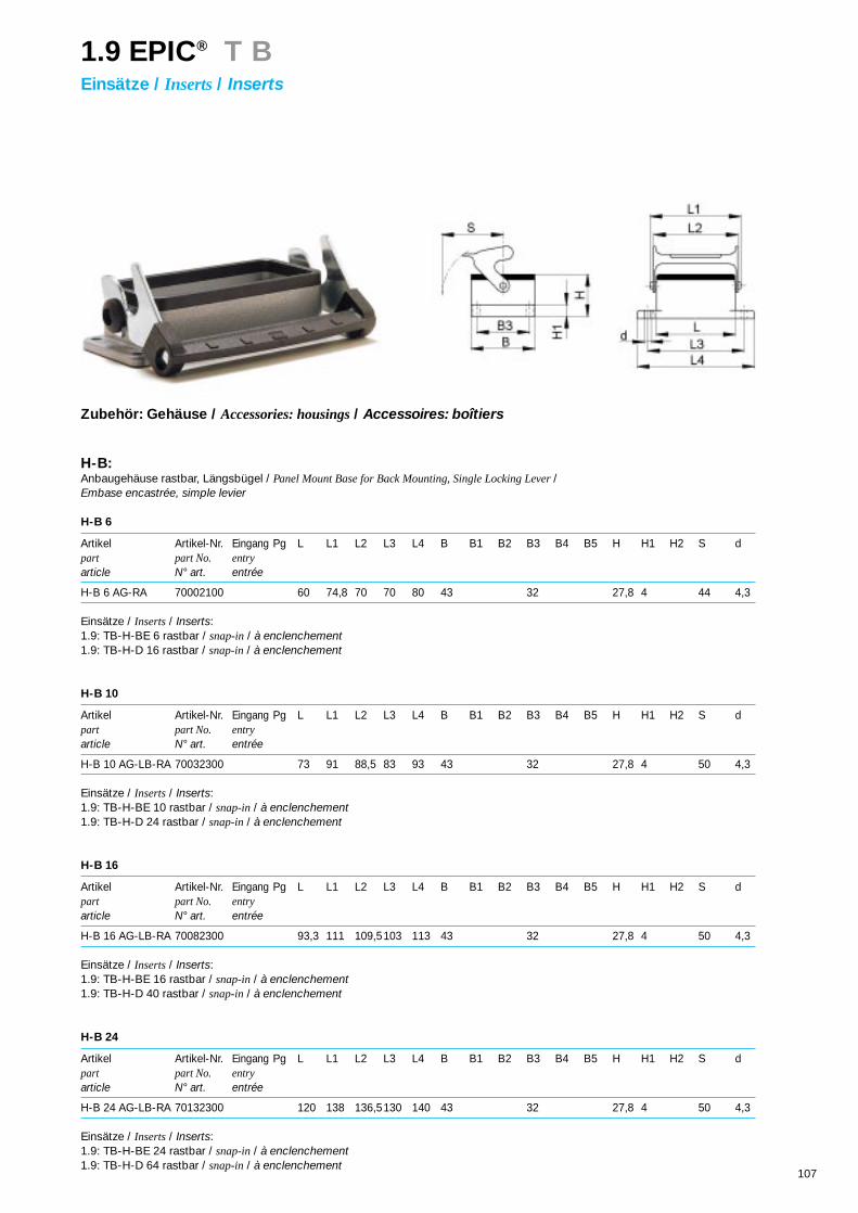
107
Zubehör: Gehäuse / Accessories: housings/ Accessoires: boîtiers
H-B: Anbaugehäuse rastbar, Längsbügel / Panel Mount Base for Back Mounting, Single Locking Lever / Embase encastrée, simple levier
H-B 6
Artikel Artikel-Nr. Eingang Pg L L1 L2 L3 L4 B B1 B2 B3 B4 B5 H H1 H2 S dpart part No. entryarticle N° art. entrée
H-B 6 AG-RA 70002100 60 74,8 70 70 80 43 32 27,8 4 44 4,3
Einsätze / Inserts/ Inserts:1.9: TB-H-BE 6 rastbar / snap-in/ à enclenchement1.9: TB-H-D 16 rastbar / snap-in/ à enclenchement
H-B 10
Artikel Artikel-Nr. Eingang Pg L L1 L2 L3 L4 B B1 B2 B3 B4 B5 H H1 H2 S dpart part No. entryarticle N° art. entrée
H-B 10 AG-LB-RA 70032300 73 91 88,5 83 93 43 32 27,8 4 50 4,3
Einsätze / Inserts/ Inserts:1.9: TB-H-BE 10 rastbar / snap-in/ à enclenchement1.9: TB-H-D 24 rastbar / snap-in/ à enclenchement
H-B 16
Artikel Artikel-Nr. Eingang Pg L L1 L2 L3 L4 B B1 B2 B3 B4 B5 H H1 H2 S dpart part No. entryarticle N° art. entrée
H-B 16 AG-LB-RA 70082300 93,3 111 109,5103 113 43 32 27,8 4 50 4,3
Einsätze / Inserts/ Inserts:1.9: TB-H-BE 16 rastbar / snap-in/ à enclenchement1.9: TB-H-D 40 rastbar / snap-in/ à enclenchement
H-B 24
Artikel Artikel-Nr. Eingang Pg L L1 L2 L3 L4 B B1 B2 B3 B4 B5 H H1 H2 S dpart part No. entryarticle N° art. entrée
H-B 24 AG-LB-RA 70132300 120 138 136,5130 140 43 32 27,8 4 50 4,3
Einsätze / Inserts/ Inserts:1.9: TB-H-BE 24 rastbar / snap-in/ à enclenchement1.9: TB-H-D 64 rastbar / snap-in/ à enclenchement
1.9 EPIC® T BEinsätze / Inserts/ Inserts

109
Die passenden Werkzeuge für
CONTACT Produkte ermöglichen eine
einfache Verarbeitung und garantieren
eine zuverlässige elektrische und me-
chanische Verbindung.
CONTACT can supply tools to satisfy
the needs of its total poduct range gu-
aranteeing reliable electrical and me-
chanical connections.
Un outillage adapté aux produits
CONTACT facilite l’installation et ga-
rantit une parfaite liaison électrique et
mécanique.
2.1 EPIC® C O N T O O LKontakte und Werkzeuge / Contacts and Tools/ Contacts et Outillage

110
Technische Daten:
Crimpkontakte:• Kontakte für Crimpanschluß: . . . gedreht, gestanzt• Kontakte: . . . . . . . . . . . . . . . . . . Kupferlegierung, versilbert/vergoldet• Anschlußquerschnitt: . . . . . . . . . 0,08 – 10 mm2
• Kontaktdurchmesser: . . . . . . . . . 1,0 – 3,6 mm
Koax – Kontakte:• Anschlußtechnik: . . . . . . . . . . . . .Crimp, Löt• Kontakte: . . . . . . . . . . . . . . . . . . .Kupferlegierung, vergoldet• Kabeltypgröße: . . . . . . . . . . . . . . RG 58• Wellenwiderstand: . . . . . . . . . . . 50 Ohm
Lichtwellenleiter – Kontakte:• Kontakte: . . . . . . . . . . . . . . . . . . Silberlegierung• Für Fasertyp: . . . . . . . . . . . . . . . .Kunststoff-Faser (POF)
Durchmesser: 1mmWellenlänge der Diode: 660 nm
• Anschlußtechnik: . . . . . . . . . . . . .Crimp
Technical Data:
Crimp Contacts• Contacts for crimp termination: . . . .machined, stamped• Contacts: . . . . . . . . . . . . . . . . . . . . . copper alloy, silver plated/gold plated• Wire gauge: . . . . . . . . . . . . . . . . . . . 0,08 – 10 mm2
• Contact diameter: . . . . . . . . . . . . . . .1,0 – 3,6 mm
Coax contacts• Wire termination: . . . . . . . . . . . . . . . crimp, solder• Contacts: . . . . . . . . . . . . . . . . . . . . . copper alloy, gold plated• Cable size: . . . . . . . . . . . . . . . . . . . . RG 58• Impedance: . . . . . . . . . . . . . . . . . . . 50 Ohm
Fibre optical contacts:• Contacts:. . . . . . . . . . . . . . . . . . . . . . silver alloy• For fibre type: . . . . . . . . . . . . . . . . . . plastic fibre
diameter: 1mmdiode wavelength: 660 nm
• Wire termination: . . . . . . . . . . . . . . . crimp
Caractéristiques techniques:• Contacts à sertir: . . . . . . . . . . . . .décolletés, estampés• Contacts: . . . . . . . . . . . . . . . . . . .alliage cuivre, argenté/doré• Raccordement: . . . . . . . . . . . . . . 0,08 – 10 mm2
• Diamètre de contacts: . . . . . . . . .1,0 – 3,6 mm
Contact koax• Raccordement: . . . . . . . . . . . . . . à sertir, à souder• Contacts: . . . . . . . . . . . . . . . . . . .alliage cuivre, doré• Taille de câbles: . . . . . . . . . . . . . .RG 58• Impédance: . . . . . . . . . . . . . . . . . 50 Ohm
Contacts pour fibre optique• Contacts: . . . . . . . . . . . . . . . . . . .alliage argente• Type de fibre: . . . . . . . . . . . . . . . fibre en plastique
diamètre: 1mmlongeur d‘onde: 660 nm
• Raccordement: . . . . . . . . . . . . . . à sertir
2.1 EPIC® C O N T O O LKontakte und Werkzeuge / Contacts and Tools/ Contacts et Outillage

111
Kontakte für Lichtwellenleiter / Contacts for fibre optics/ Contacts pour fibre optique
Artikel Version Art.Nr. Leiterdurchmesser Abisolierlänge VPEpart version part No. wire diameter stripping length packing unitarticle version N° art. diamètre du fil longueur de dénude conditionnement
(mm)
LWL Stift / male/ mâle 11214100 1,0 mm POF/FO 19 1
Buchse / female/ femelle 11219100 1,0 mm POF/FO 14 1
Einsätze / Inserts/ Inserts: 1.8: MCS 10 CM / MCB 10 CM1.6: H-D 7 für gedrehte Kontakte / 1.6: H-D 7 for machined contacts /1.6: H-D 7 pour contacts décolletés
Werkzeuge / Tools / Outillage
Artikel Leiterdurchmesser Art.Nr.part wire diameter part No.article diamètre du fil N° art.
LWL Montage Set / Fibre optic assembly set /Montage set pour fibre optique 1,0 mm POF/FO 11184700
Einzelartikel / Single parts / Seule articles
Artikel für Leiterdurchmesser optische Faser Art.Nr.part for wire diameter optical fibre part No.article diamètre du fil pour fibre optique N° art.
Crimpzange / crimping tool / pince à setir 1,0 mm 11184000
Kontaktaufnahme / locator / positionneur 11184100
Faserabisolierer für POF-Kabel 11184200stripping tool for fibre optic cableoutillage de dénuder pour cable fibre optique
Messer / knife / couteau 11184300
Polierpapier / polishing paper / papier de polissage 11184400
Polierplatte / polishing plate / planche de polissage 11184500
Lösewerkzeug / removal tool / outil de demontage 11161000*
2.1 EPIC® C O N T O O LKontakte und Werkzeuge / Contacts and Tools/ Contacts et Outillage

112
H-D / H-DD / MC gedrehte Kontakte - Kontaktdurchmesser 1,6 mmH-D / H-DD / MC machined contacts - contact diameter 1,6 mmH-D / H-DD / MC contacts décolletés - contact diamètre 1,6 mm
Artikel Version Art.Nr. Leiterquerschnitt Abisolierlänge Oberfläche VPEpart version part No. wire gauge stripping length plating packing unitarticle version N° art. section longueur de dénuder surface conditionnement
(mm2) (mm)
H-D 1,6 Stift / male/ mâle 13162000* 0,14 - 0,37 8,0 Ag 100
gedreht Buchse / female/ femelle 13163000* 0,14 - 0,37 8,0 Ag 100
machined Stift / male/ mâle 13162100* 0,5 8,0 Ag 100
décolleté Buchse / female/ femelle 13163100* 0,5 8,0 Ag 100
Stift / male/ mâle 13162200* 0,75 - 1,0 8,0 Ag 100
Buchse / female/ femelle 13163200* 0,75 - 1,0 8,0 Ag 100
Stift / male/ mâle 13162300* 1,5 8,0 Ag 100
Buchse / female/ femelle 13163300* 1,5 8,0 Ag 100
Stift / male/ mâle 13162400* 2,5 5,8 Ag 100
Buchse / female/ femelle 13163400* 2,5 5,8 Ag 100
Stift / male/ mâle 13162500* 0,14 - 0,37 8,0 Au 100
Buchse / female/ femelle 13163500* 0,14 - 0,37 8,0 Au 100
Stift / male/ mâle 13162600* 0,5 8,0 Au 100
Buchse / female/ femelle 13163600* 0,5 8,0 Au 100
Stift / male/ mâle 13162700* 0,75 - 1,0 8,0 Au 100
Buchse / female/ femelle 13163700* 0,75 - 1,0 8,0 Au 100
Stift / male/ mâle 13162800* 1,5 8,0 Au 100
Buchse / female/ femelle 13163800* 1,5 8,0 Au 100
Einsätze / Inserts/ Inserts: 1.8: MCS 10 CM, MCB 10 CM1.6 / 1.7: H-D / H-DD Einsätze für gedrehte Kontakte1.6 / 1.7: H-D / H-DD inserts for machined contacts1.6 / 1.7: H-D / H-DD inserts pour contacts décolletés
2.1 EPIC® C O N T O O LKontakte und Werkzeuge / Contacts and Tools/ Contacts et Outillage

113
Werkzeuge / Tools / Outillage
Artikel Leiterquerschnitt Art.Nr.part wire gauge part No.article section N° art.
Locator Crimpbacken Crimpwerkzeuglocator crimp dies crimping toolinsert centreur machoire outil de sertissage
Lösewerkzeuge für Kontakte 11161000*removal tool for contactsoutil de demontage pour contacts
Crimpzange 0,14 - 2,5 mm2 11147200 11147100 11147000crimping toolpince à sertir
2.1 EPIC® C O N T O O LKontakte und Werkzeuge / Contacts and Tools/ Contacts et Outillage

114
MC gedrehte Kontakte - Kontaktdurchmesser 2,5 mmMC machined contacts - contact diameter 2,5 mmMC contacts décolletés - contact diamètre 2,5 mm
Artikel Version Art.Nr. Leiterquerschnitt Abisolierlänge Oberfläche VPEpart version part No. wire gauge stripping length plating packing unitarticle version N° art. section longueur de dénuder surface conditionnement
(mm2) (mm)
MC 2,5 Stift / male/ mâle 11213000 0,5 7,8 Ag 100
gedreht Buchse / female/ femelle 11218000 0,5 7,8 Ag 100
machined Stift / male/ mâle 11213100* 0,75 - 1,0 7,8 Ag 100
décolleté Buchse / female/ femelle 11218100* 0,75 - 1,0 7,8 Ag 100
Stift / male/ mâle 11213200* 1,5 7,8 Ag 100
Buchse / female/ femelle 11218200* 1,5 7,8 Ag 100
Stift / male/ mâle 11213300* 2,5 7,8 Ag 100
Buchse / female/ femelle 11218300* 2,5 7,8 Ag 100
Stift / male/ mâle 11213400* 4,0 7,8 Ag 100
Buchse / female/ femelle 11218400* 4,0 7,8 Ag 100
Einsätze / Inserts/ Inserts: 1.8: MCS 5 CM, MCB 5 CM
2.1 EPIC® C O N T O O LKontakte und Werkzeuge / Contacts and Tools/ Contacts et Outillage

115
Werkzeuge / Tools / Outillage
Artikel Leiterquerschnitt Art.Nr.part wire gauge part No.article section N° art.
Locator Crimpbacken Crimpwerkzeuglocator crimp dies crimping toolinsert centreur machoire outil de sertissage
Lösewerkzeuge für Kontakte 11171000removal tool for contactsoutil de demontage pour contacts
Crimpzange 0,5 - 4,0 mm2 11147200 11147100 11147000crimping toolpince à sertir
2.1 EPIC® C O N T O O LKontakte und Werkzeuge / Contacts and Tools/ Contacts et Outillage

116
H-BE gedrehte Kontakte - Kontaktdurchmesser 2,5 mmH-BE machined contacts - contact diameter 2,5 mmH-BE contacts décolletés - contact diamètre 2,5 mm
Artikel Version Art.Nr. Leiterquerschnitt Abisolierlänge Oberfläche VPEpart version part No. wire gauge stripping length plating packing unitarticle version N° art. section longueur de dénuder surface conditionnement
(mm2) (mm)
H-BE 2,5 Stift / male/ mâle 11190000 0,5 7,4 Ag 100
gedreht Buchse / female/ femelle 11195000 0,5 7,3 Ag 100
machined Stift / male/ mâle 11190100 0,75 - 1,0 7,4 Ag 100
décolleté Buchse / female/ femelle 11195100 0,75 - 1,0 7,3 Ag 100
Stift / male/ mâle 11190200* 1,5 7,4 Ag 100
Buchse / female/ femelle 11195200* 1,5 7,3 Ag 100
Stift / male/ mâle 11190300 2,5 7,4 Ag 100
Buchse / female/ femelle 11195300 2,5 7,3 Ag 100
Stift / male/ mâle 11190400 4,0 7,4 Ag 100
Buchse / female/ femelle 11195400 4,0 7,3 Ag 100
Stift / male/ mâle 11192000 0,5 7,4 Au 100
Buchse / female/ femelle 11197000 0,5 7,3 Au 100
Stift / male/ mâle 11192100 0,75 - 1,0 7,4 Au 100
Buchse / female/ femelle 11197100 0,75 - 1,0 7,3 Au 100
Stift / male/ mâle 11192200 1,5 7,4 Au 100
Buchse / female/ femelle 11197200 1,5 7,3 Au 100
Einsätze / Inserts/ Inserts: 1.8: H-E Modul / H-E module / module H-E1.3: H-BE Einsätze für gedrehte Kontakte1.3: H-BE inserts for machined contacts 1.3: H-BE inserts pour contacts décolletés
2.1 EPIC® C O N T O O LKontakte und Werkzeuge / Contacts and Tools/ Contacts et Outillage

117
Werkzeuge / Tools / Outillage
Artikel Leiterquerschnitt Art.Nr.part wire gauge part No.article section N° art.
Locator Crimpbacken Crimpwerkzeuglocator crimp dies crimping toolinsert centreur machoire outil de sertissage
Crimpzange 0,5 - 4,0 mm2 11147200 11147100 11147000crimping toolpince à sertir
Lösewerkzeug für Kontakte / H-E Modul (MC 4CM) 11182500removal tool for contacts / H-E module (MC 4 CM)outil de demontage pour contacts / module H-E (MC 4 CM)
2.1 EPIC® C O N T O O LKontakte und Werkzeuge / Contacts and Tools/ Contacts et Outillage

118
MC gedrehte Kontakte - Kontaktdurchmesser 3,6 mmMC machined contacts - contact diameter 3,6 mmMC contacts décolletés - contact diamètre 3,6 mm
Artikel Version Art.Nr. Leiterquerschnitt Abisolierlänge Oberfläche VPEpart version part No. wire gauge stripping length plating packing unitarticle version N° art. section longueur de dénuder surface conditionnement
(mm2) (mm)
MC 3,6 Stift / male/ mâle 11210700 1,5 10,0 Ag 100
gedreht Buchse / female/ femelle 11215700 1,5 10,0 Ag 100
machined Stift / male/ mâle 11210600 2,5 10,0 Ag 100
décolleté Buchse / female/ femelle 11215600 2,5 10,0 Ag 100
Stift / male/ mâle 11210000 4,0 10,0 Ag 100
Buchse / female/ femelle 11215000* 4,0 10,0 Ag 100
Stift / male/ mâle 11210100* 6,0 10,0 Ag 100
Buchse / female/ femelle 11215100* 6,0 10,0 Ag 100
Stift / male/ mâle 11210200 10,0 10,0 Ag 100
Buchse / female/ femelle 11215200 10,0 10,0 Ag 100
Einsätze / Inserts/ Inserts: 1.8: MCS 3 CM / MCB 3 CM
2.1 EPIC® C O N T O O LKontakte und Werkzeuge / Contacts and Tools/ Contacts et Outillage

119
Werkzeuge / Tools / Outillage
Artikel Leiterquerschnitt Art.Nr.part wire gauge part No.article section N° art.
Locator Crimpbacken Crimpwerkzeuglocator crimp dies crimping toolinsert centreur machoire outil de sertissage
Lösewerkzeuge für Kontakte 11171100*removal tool for contactsoutil de demontage pour contacts
Crimpzange 1,5 - 2,5 mm2 11147210 11147110 11147000crimping tool 4,0 - 10,0 mm2 11147120pince à sertir
2.1 EPIC® C O N T O O LKontakte und Werkzeuge / Contacts and Tools/ Contacts et Outillage

120
H-D / MC gestanzte Kontakte - Kontaktdurchmesser 1,6 mmH-D / MC stamped contacts - contact diameter 1,6 mmH-D / MC contacts estampés - contact diamètre 1,6 mm
Artikel Version Art.Nr. Leiterquerschnitt Abisolierlänge Oberfläche VPEpart version part No. wire gauge stripping length plating packing unitarticle version N° art. section longueur de dénuder surface conditionnement
(mm2) (mm)
H-D 1,6 Stift / male/ mâle 11241100 0,14 - 0,5 2,5 + 0,5 Ag 100
gestanzt Buchse / female/ femelle 11231100 0,14 - 0,5 2,5 + 0,5 Ag 100
stamped Stift / male/ mâle 11221000 0,5 - 1,5 3,5 + 0,5 Ag 100
estampé Buchse / female/ femelle 11236100 0,5 - 1,5 3,5 + 0,5 Ag 100
Stift / male/ mâle 11223500 1,5 - 2,5 3,5 + 0,5 Ag 100
Buchse / female/ femelle 11228500 1,5 - 2,5 3,5 + 0,5 Ag 100
Stift / male/ mâle 11243100 0,14 - 0,5 2,5 + 0,5 Au 100
Buchse / female/ femelle 11233100 0,14 - 0,5 2,5 + 0,5 Au 100
Stift / male/ mâle 11221300 0,5 - 1,5 3,5 + 0,5 Au 100
Buchse / female/ femelle 11238100 0,5 - 1,5 3,5 + 0,5 Au 100
Einsätze / Inserts/ Inserts: 1.8: MCS 10 CG / MCB 10 CG1.6: H-D Einsätze für gestanzte Kontakte1.6: H-D inserts for stamped contacts 1.6: H-D inserts pour contacts estampés
2.1 EPIC® C O N T O O LKontakte und Werkzeuge / Contacts and Tools/ Contacts et Outillage

121
Werkzeuge / Tools / Outillage
Artikel Leiterquerschnitt Art.Nr.part wire gauge part No.article section N° art.
Locator Crimpbacken Crimpwerkzeuglocator crimp dies crimping toolinsert centreur machoire outil de sertissage
Lösewerkzeuge für Kontakte 11161000*removal tool for contactsoutil de demontage pour contacts
Crimpzange 0,14 - 0,5 mm2 11147300 11147170 11147000crimping tool 0,5 - 1,5 mm2 11147180pince à sertir 1,5 - 2,5 mm2 11147190
2.1 EPIC® C O N T O O LKontakte und Werkzeuge / Contacts and Tools/ Contacts et Outillage

122
MC gestanzte Kontakte - Kontaktdurchmesser 2,5 mmMC stamped contacts - contact diameter 2,5 mmMC contacts estampés - contact diamètre 2,5 mm
Artikel Version Art.Nr. Leiterquerschnitt Abisolierlänge Oberfläche VPEpart version part No. wire gauge stripping length plating packing unitarticle version N° art. section longueur de dénuder surface conditionnement
(mm2) (mm)
MC 2,5 Stift / male/ mâle 11201000 0,5 - 1,5 mm2 3,5 + 0,5 Ag 100
gestanzt Buchse / female/ femelle 11205000 0,5 - 1,5 mm2 3,5 + 0,5 Ag 100
stamped Stift / male/ mâle 11202000 1,5 - 2,5 mm2 3,5 + 0,5 Ag 100
estampé Buchse / female/ femelle 11206000 1,5 - 2,5 mm2 3,5 + 0,5 Ag 100
Einsätze / Inserts/ Inserts: 1.8: MCS 5 CG / MCB 5 CG
2.1 EPIC® C O N T O O LKontakte und Werkzeuge / Contacts and Tools/ Contacts et Outillage

123
Werkzeuge / Tools / Outillage
Artikel Leiterquerschnitt Art.Nr.part wire gauge part No.article section N° art.
Locator Crimpbacken Crimpwerkzeuglocator crimp dies crimping toolinsert centreur machoire outil de sertissage
Lösewerkzeuge für Kontakte 11160000removal tool for contactsoutil de demontage pour contacts
Crimpzange 0,5 - 1,5 mm2 11147300 11147180 11147000crimping tool 1,5 - 2,5 mm2 11147190pince à sertir
2.1 EPIC® C O N T O O LKontakte und Werkzeuge / Contacts and Tools/ Contacts et Outillage

124
MC / M-D gestanzte Band-Kontakte - Kontaktdurchmesser 1,0 mmMC / M-D stamped contacts on reel - contact diameter 1,0 mmMC / M-D contacts estampés en bande - contact diamètre 1,0 mm
Artikel Version Art.Nr. Leiterquerschnitt Abisolierlänge Oberfläche Kontaktzuführung VPEpart version part No. wire gauge stripping length plating contact feeding packing unitarticle version N° art. section longueur de surface indtruduction condition-
dénuder nement(mm2) (mm)
M-D 1,0 Stift / male/ mâle 11302500 0,08 - 0,2 2,5 + 0,5 Au links / left / gauche 300
gestanzt Buchse / female/ femelle 11302700 0,08 - 0,2 2,5 + 0,5 Au links / left / gauche 300
stamped Stift / male/ mâle 11302600 0,2 - 0,52 2,5 + 0,5 Au links / left / gauche 300
estampé Buchse / female/ femelle 11302800 0,2 - 0,52 2,5 + 0,5 Au links / left / gauche 300
Einsätze / Inserts/ Inserts: MCS 20 CG / MCB 20 CG
2.1 EPIC® C O N T O O LKontakte und Werkzeuge / Contacts and Tools/ Contacts et Outillage
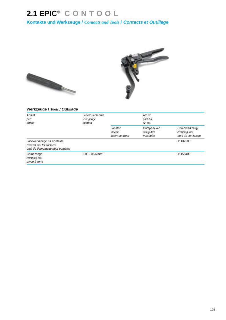
125
Werkzeuge / Tools / Outillage
Artikel Leiterquerschnitt Art.Nr.part wire gauge part No.article section N° art.
Locator Crimpbacken Crimpwerkzeuglocator crimp dies crimping toolinsert centreur machoire outil de sertissage
Lösewerkzeuge für Kontakte 11132500removal tool for contactsoutil de demontage pour contacts
Crimpzange 0,08 - 0,56 mm2 11158400crimping toolpince à sertir
2.1 EPIC® C O N T O O LKontakte und Werkzeuge / Contacts and Tools/ Contacts et Outillage

126
H-D / MC gestanzte Band-Kontakte - Kontaktdurchmesser 1,6 mmH-D / MC stamped contacts on reel - contact diameter 1,6 mmH-D / MC contacts estampés en bande - contact diamètre 1,6 mm
Artikel Version Art.Nr. Leiterquerschnitt Abisolierlänge Oberfläche Kontaktzuführung VPEpart version part No. wire gauge stripping length plating contact feeding packing unitarticle version N° art. section longueur de surface indtruduction condition-
dénuder nement(mm2) (mm)
H-D 1,6 Stift / male/ mâle 11240700 0,14 - 0,5 2,5 + 0,5 Ag links / left / gauche 200
gestanzt Buchse / female/ femelle 11230700 0,14 - 0,5 2,5 + 0,5 Ag links / left / gauche 200
stamped Stift / male/ mâle 11220700 0,5 - 1,5 3,5 + 0,5 Ag links / left / gauche 200
estampé Buchse / female/ femelle 11235700 0,5 - 1,5 3,5 + 0,5 Ag links / left / gauche 200
Stift / male/ mâle 11223000 1,5 - 2,5 3,5 + 0,5 Ag links / left / gauche 200
Buchse / female/ femelle 11228000 1,5 - 2,5 3,5 + 0,5 Ag links / left / gauche 200
Einsätze / Inserts/ Inserts: 1.8: MCS 10 CG / MCB 10 CG1.6: H-D Einsätze für gestanzte Kontakte1.6: H-D inserts for stamped contacts 1.6: H-D inserts pour contacts estampés
2.1 EPIC® C O N T O O LKontakte und Werkzeuge / Contacts and Tools/ Contacts et Outillage

127
Werkzeuge / Tools / Outillage
Artikel Leiterquerschnitt Art.Nr.part wire gauge part No.article section N° art.
Locator Crimpbacken Crimpwerkzeuglocator crimp dies crimping toolinsert centreur machoire outil de sertissage
Lösewerkzeuge für Kontakte 11161000*removal tool for contactsoutil de demontage pour contacts
Crimpzange 0,14 - 0,5 mm2 11153600 11153500crimping tool 0,5 - 1,5 mm2 11153700pince à sertir 1,5 - 2,5 mm2 11153800
2.1 EPIC® C O N T O O LKontakte und Werkzeuge / Contacts and Tools/ Contacts et Outillage

128
MC gestanzte Band-Kontakte - Kontaktdurchmesser 2,5 mmMC stamped contacts on reel - contact diameter 2,5 mmMC contacts estampés en bande - contact diamètre 2,5 mm
Artikel Version Art.Nr. Leiterquerschnitt Abisolierlänge Oberfläche Kontaktzuführung VPEpart version part No. wire gauge stripping length plating contact feeding packing unitarticle version N° art. section longueur de surface indtroduction condition-
dénuder nement(mm2) (mm)
MC 2,5 Stift / male/ mâle 11208000 0,5 - 1,5 3,5 + 0,5 Ag links / left / gauche 200
gestanzt Buchse / female/ femelle 11209000 0,14 - 0,5 3,5 + 0,5 Ag links / left / gauche 200
stamped Stift / male/ mâle 11208500 1,5 - 2,5 3,5 + 0,5 Ag links / left / gauche 200
estampé Buchse / female/ femelle 11209500 1,5 - 2,5 3,5 + 0,5 Ag links / left / gauche 200
Einsätze / Inserts/ Inserts: 1.8: MCS 5 CG / MCB 5 CG
2.1 EPIC® C O N T O O LKontakte und Werkzeuge / Contacts and Tools/ Contacts et Outillage

129
Werkzeuge / Tools / Outillage
Artikel Leiterquerschnitt Art.Nr.part wire gauge part No.article section N° art.
Locator Crimpbacken Crimpwerkzeuglocator crimp dies crimping toolinsert centreur machoire outil de sertissage
Lösewerkzeuge für Kontakte 11160000removal tool for contactsoutil de demontage pour contacts
Crimpzange 0,5 - 1,5 mm2 11153700 11153500crimping tool 1,5 - 2,5 mm2 11153800pince à sertir
2.1 EPIC® C O N T O O LKontakte und Werkzeuge / Contacts and Tools/ Contacts et Outillage

130
KOAX-KontakteCoax contactsContacts coax
Artikel Version Art.Nr. Leiterquerschnitt E F G Oberfläche VPEpart version part No. wire gauge plating packing unitarticle version N° art. section surface conditionnement
KOAX Stift / male/ mâle 11214200 RG 58 9,5 7,9 2 Au 1
Buchse / female/ femelle 11219200 RG 58 9,5 7,9 2 Au 1
Einsätze / Inserts/ Inserts: 1.8: MCS 5 KOAX / MCB 5 KOAX
2.1 EPIC® C O N T O O LKontakte und Werkzeuge / Contacts and Tools/ Contacts et Outillage

131
Werkzeuge / Tools / Outillage
Artikel Kabelgröße Art.Nr.part wire size part No.article grandeur dufil N° art.
Locator Crimpbacken Crimpwerkzeuglocator crimp dies crimping toolinsert centreur machoire outil de sertissage
Lösewerkzeuge für Kontakte 11171100removal tool for contactsoutil de demontage pour contacts
Crimpzange RG58 11147130 11147000crimping toolpince à sertir
2.1 EPIC® C O N T O O LKontakte und Werkzeuge / Contacts and Tools/ Contacts et Outillage
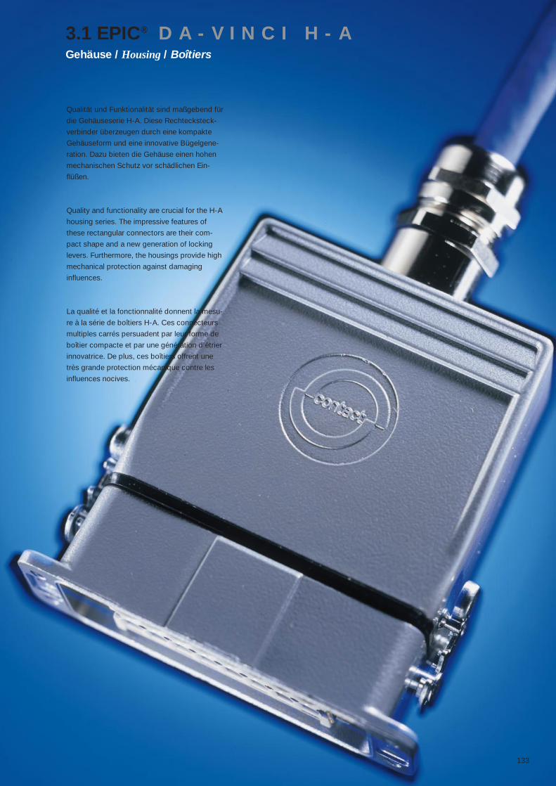
133
Qualität und Funktionalität sind maßgebend für
die Gehäuseserie H-A. Diese Rechtecksteck-
verbinder überzeugen durch eine kompakte
Gehäuseform und eine innovative Bügelgene-
ration. Dazu bieten die Gehäuse einen hohen
mechanischen Schutz vor schädlichen Ein-
flüßen.
Quality and functionality are crucial for the H-A
housing series. The impressive features of
these rectangular connectors are their com-
pact shape and a new generation of locking
levers. Furthermore, the housings provide high
mechanical protection against damaging
influences.
La qualité et la fonctionnalité donnent la mesu-
re à la série de boîtiers H-A. Ces connecteurs
multiples carrés persuadent par leur forme de
boîtier compacte et par une génération d’étrier
innovatrice. De plus, ces boîtiers offrent une
très grande protection mécanique contre les
influences nocives.
3.1 EPIC® D A - V I N C I H - AGehäuse / Housing / Boîtiers

134
Technische Daten:Vorschriften: DIN 43652Temperaturbereich: -40°C - +125°CSchutzart: IP 65 (H-A 10 / 16 / 32 / 48)IP-Schutzart für H-A 3 Metallgehäuse ist abhängig vom verwendeten EinsatzWerkstoff:H-A 3: Zinkdruckguß, pulverbeschichtet / Thermoplast, Brandverhalten nach UL 94 V-0H-A 10 – 48: Aluminiumlegierung, pulverbeschichtet
Technical Data:Specifications: DIN 43652Temperature range: -40°C - +125°CProtection class: IP 65 ( H-A 10 / 16 / 32 / 48)IP for H-A 3 metal housing depends on the insert typeMaterial:H-A 3: Die cast zinc, powder coated / Thermoplast, flame retardent material rated UL 94 V-0H-A 10 – 48: aluminium alloy, powder coated
Caractéristiques techniques:Réglements: DIN 43652Gamme de température: -40°C - +125°CDegré de protection: IP 65 (H-A 3 10 / 16 / 32 / 48)IP pour H-A 3 boîtier dépendent d’insertMatière:H-A 3: Zinc moulé par injection, recouvert par pulvérisation / plastique thermoformé, résistance au feu suivant UL 94 V-0H-A 10 – 48: Alliage aluminium, recouvert par pulvérisation
H-A 3: Zinkdruckguß, pulverbeschichtet (grau) / Thermoplast, Brandverhalten nach UL 94 V-0H-A 3: Die cast zinc, powder coated (grey) / Thermoplast, flame retardent material rated UL 94 V-0H-A 3: Zinc moulé par injection, recouvert par pulvérisation (grise) / plastique thermoformé, ré-sistance au feu suivant UL 94 V-0
Für den industriellen Einsatz in anspruchsvoller UmgebungFor industrial applications in demanding environments.Pour une exploitation industrielle dans un environnement exigeant.
H-A 10 – 48: Aluminiumlegierung, pulverbeschichtet (grau), Bügel und Bolzen aus verzinktemStahl H-A 10 – 48: aluminium alloy, powder coated (grey), locking levers and bolts made of zinc plated steel H-A 10 – 48: Alliage aluminium, recouvert par pulvérisation (grise), leviers et ergots acier recou-vert par zinc
Für den industriellen Einsatz in anspruchsvoller UmgebungFor industrial applications in demanding environments.Pour une exploitation industrielle dans un environnement exigeant.
EP: (Environmental Protected)H-A 10 – 48: Aluminiumlegierung, pulverbeschichtet (schwarz), Bügel und Bolzen aus Edel-stahlH-A 10 – 48: aluminium alloy, powder coated (black), locking levers and bolts made of stainless steelH-A 10 – 48: Alliage aluminium, recouvert par pulvérisation (noir), leviers et ergots acier inox
Für den industriellen Einsatz in stark beanspruchter Umgebung mit aggressiver AtmosphäreFor industrial applications in extremely demanding environments with aggressive atmospheresPour l’exploitation industrielle dans un environnement très sollicité à atmosphère agressive
3.1 EPIC® D A - V I N C I H - AGehäuse / Housing / Boîtiers
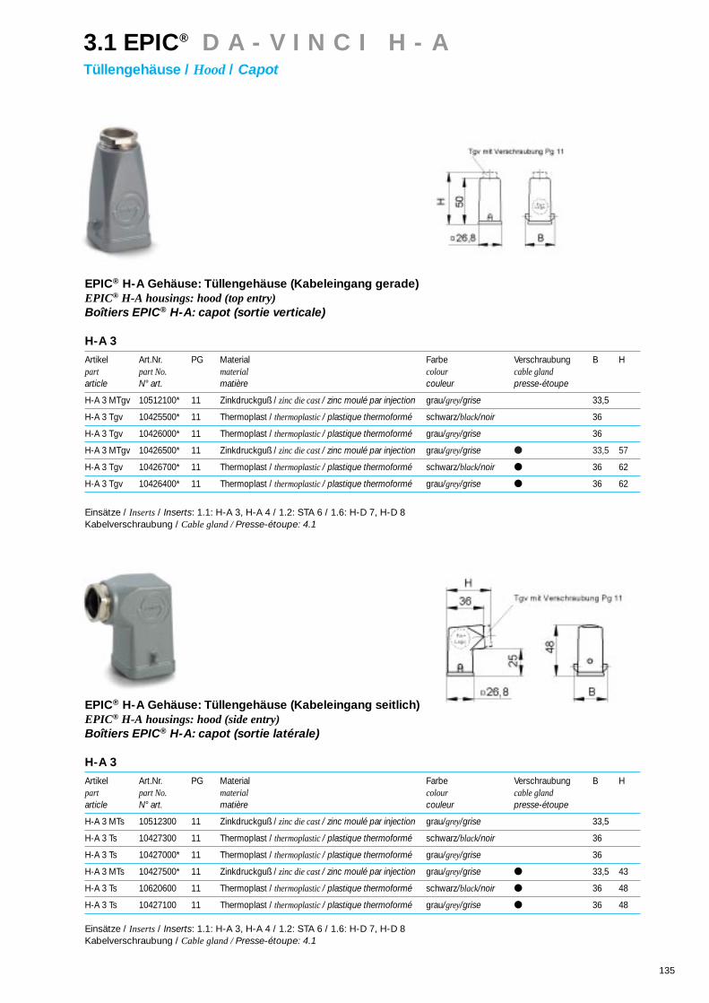
135
EPIC® H-A Gehäuse: Tüllengehäuse (Kabeleingang gerade)EPIC® H-A housings: hood (top entry)Boîtiers EPIC® H-A: capot (sortie verticale)
H-A 3
Artikel Art.Nr. PG Material Farbe Verschraubung B Hpart part No. material colour cable glandarticle N° art. matière couleur presse-étoupe
H-A 3 MTgv 10512100* 11 Zinkdruckguß / zinc die cast / zinc moulé par injection grau/grey/grise 33,5
H-A 3 Tgv 10425500* 11 Thermoplast / thermoplastic / plastique thermoformé schwarz/black/noir 36
H-A 3 Tgv 10426000* 11 Thermoplast / thermoplastic / plastique thermoformé grau/grey/grise 36
H-A 3 MTgv 10426500* 11 Zinkdruckguß / zinc die cast / zinc moulé par injection grau/grey/grise 33,5 57
H-A 3 Tgv 10426700* 11 Thermoplast / thermoplastic / plastique thermoformé schwarz/black/noir 36 62
H-A 3 Tgv 10426400* 11 Thermoplast / thermoplastic / plastique thermoformé grau/grey/grise 36 62
Einsätze / Inserts/ Inserts: 1.1: H-A 3, H-A 4 / 1.2: STA 6 / 1.6: H-D 7, H-D 8Kabelverschraubung / Cable gland / Presse-étoupe: 4.1
EPIC® H-A Gehäuse: Tüllengehäuse (Kabeleingang seitlich)EPIC® H-A housings: hood (side entry)Boîtiers EPIC® H-A: capot (sortie latérale)
H-A 3
Artikel Art.Nr. PG Material Farbe Verschraubung B Hpart part No. material colour cable glandarticle N° art. matière couleur presse-étoupe
H-A 3 MTs 10512300 11 Zinkdruckguß / zinc die cast / zinc moulé par injection grau/grey/grise 33,5
H-A 3 Ts 10427300 11 Thermoplast / thermoplastic / plastique thermoformé schwarz/black/noir 36
H-A 3 Ts 10427000* 11 Thermoplast / thermoplastic / plastique thermoformé grau/grey/grise 36
H-A 3 MTs 10427500* 11 Zinkdruckguß / zinc die cast / zinc moulé par injection grau/grey/grise 33,5 43
H-A 3 Ts 10620600 11 Thermoplast / thermoplastic / plastique thermoformé schwarz/black/noir 36 48
H-A 3 Ts 10427100 11 Thermoplast / thermoplastic / plastique thermoformé grau/grey/grise 36 48
Einsätze / Inserts/ Inserts: 1.1: H-A 3, H-A 4 / 1.2: STA 6 / 1.6: H-D 7, H-D 8Kabelverschraubung / Cable gland / Presse-étoupe: 4.1
3.1 EPIC® D A - V I N C I H - ATüllengehäuse / Hood / Capot

136
EPIC® H-A Gehäuse: Tüllengehäuse (Kabeleingang gerade, Bolzen für Längsbügel)EPIC® H-A housings: hood (top entry, bolts for single locking lever)Boîtiers EPIC® H-A: capot (sortie verticale, ergots pour simple levier)
H-A 10
Artikel Art.Nr. Art.Nr.: EP PG L L1 L2 L3 L4 B B1 B2 B3 B4 B5 H H1 H2 S dpart part No. part No: EParticle N° art. N° art.: EP
H-A 10 TG 13,5 10446000* 13,5
H-A 10 TG 16 10446100* 70461000 1663 73 29,5 53,3
Einsätze / Inserts/ Inserts: 1.1: H-A 10 / 1.2: STA 14 / 1.6: H-D 15Deckel / Cover/ Couvercle: 5.1: H-A 10Kabelverschraubung / Cable gland / Presse-étoupe: 4.1
H-A 16
Artikel Art.Nr. Art.Nr.: EP PG L L1 L2 L3 L4 B B1 B2 B3 B4 B5 H H1 H2 S dpart part No. part No: EParticle N° art. N° art.: EP
H-A 16 TG 16 10565000* 70491000 16
H-A 16 TG 21 10565300* 2179 89 29,5 58,3
Einsätze / Inserts/ Inserts: 1.1: H-A 16 / 1.2: STA 20 / 1.6: H-D 25Deckel / Cover/ Couvercle: 5.1: H-A 16Kabelverschraubung / Cable gland / Presse-étoupe: 4.1
EPIC® H-A Gehäuse: Tüllengehäuse (Kabeleingang gerade, Bolzen für Längsbügel, hohe Bauform)EPIC® H-A housings: hood (top entry, bolts for single locking lever, high version)Boîtiers EPIC® H-A: capot (sortie verticale, ergots pour simple levier, version haute)
H-A 10
Artikel Art.Nr. Art.Nr.: EP PG L L1 L2 L3 L4 B B1 B2 B3 B4 B5 H H1 H2 S dpart part No. part No: EParticle N° art. N° art.: EP
H-A 10 TGH 16 70460200 70461200 16
H-A 10 TGH 21 70460400 70461400 2163 73 29,5 67,3
Einsätze / Inserts/ Inserts: 1.1: H-A 10 / 1.2: STA 14 / 1.6: H-D 15Deckel / Cover/ Couvercle: 5.1: H-A 10Kabelverschraubung / Cable gland / Presse-étoupe: 4.1
H-A 16
Artikel Art.Nr. Art.Nr.: EP PG L L1 L2 L3 L4 B B1 B2 B3 B4 B5 H H1 H2 S dpart part No. part No: EParticle N° art. N° art.: EP
H-A 16 TGH 16 70490200 70491200 16
H-A 16 TGH 21 70490400 70491400 2179 89 29,5 72,3
Einsätze / Inserts/ Inserts: 1.1: H-A 16 / 1.2: STA 20 / 1.6: H-D 25Deckel / Cover/ Couvercle: 5.1: H-A 16Kabelverschraubung / Cable gland / Presse-étoupe: 4.1
3.1 EPIC® D A - V I N C I H - ATüllengehäuse / Hood / Capot

137
EPIC® H-A Gehäuse: Tüllengehäuse (Kabeleingang gerade, Bolzen für Querbügel)EPIC® H-A housings: hood (top entry, bolts for double locking lever)Boîtiers EPIC® H-A: capot (sortie verticale, ergots pour double levier)
H-A 32
Artikel Art.Nr. Art.Nr.: EP PG L L1 L2 L3 L4 B B1 B2 B3 B4 B5 H H1 H2 S dpart part No. part No: EParticle N° art. N° art.: EP
H-A 32 TG 21 10582000* 70521200 21
H-A 32 TG 29 10583000* 70521400 2982 49,6 56 70,8 75
Einsätze / Inserts/ Inserts: 1.1: H-A 32 / 1.2: 2 x STA 20 / 1.6: H-D 50Deckel / Cover/ Couvercle: 5.1: H-A 32Kabelverschraubung / Cable gland / Presse-étoupe: 4.1
H-A 48
Artikel Art.Nr. Art.Nr.: EP PG L L1 L2 L3 L4 B B1 B2 B3 B4 B5 H H1 H2 S dpart part No. part No: EParticle N° art. N° art.: EP
H-A 48 TG 29 10631800 – 29 93,5 64,5 79 89,5 95
Einsätze / Inserts/ Inserts: 1.1: H-A 48Kabelverschraubung / Cable gland / Presse-étoupe: 4.1
EPIC® H-A Gehäuse: Tüllengehäuse (Kabeleingang gerade, Querbügel)EPIC® H-A housings: hood (top entry, double locking lever)Boîtiers EPIC® H-A: capot (sortie verticale, double levier)
H-A 32
Artikel Art.Nr. Art.Nr.: EP PG L L1 L2 L3 L4 B B1 B2 B3 B4 B5 H H1 H2 S dpart part No. part No: EParticle N° art. N° art.: EP
H-A 32 TGB 21 10584000 70526200 21
H-A 32 TGB 29 10585000 70526400 2982 49,6 56 70,8 66 75 124,5
Einsätze / Inserts/ Inserts: 1.1: H-A 32 / 1.2: 2 x STA 20 / 1.6: H-D 50Deckel / Cover/ Couvercle: 5.1: H-A 32Kabelverschraubung / Cable gland / Presse-étoupe: 4.1
3.1 EPIC® D A - V I N C I H - ATüllengehäuse / Hood / Capot

138
EPIC® H-A Gehäuse: Tüllengehäuse (Kabeleingang seitlich, Bolzen für Längsbügel)EPIC® H-A housings: hood (side entry, bolts for single locking lever)Boîtiers EPIC® H-A: capot (sortie latérale, ergots pour simple levier)
H-A 10
Artikel Art.Nr. Art.Nr.: EP PG L L1 L2 L3 L4 B B1 B2 B3 B4 B5 H H1 H2 S dpart part No. part No: EParticle N° art. N° art.: EP
H-A 10 TS 16 10445000* 70463000 16
H-A 10 TS 21 10445500* 2163 73 29,5 53,3
Einsätze / Inserts/ Inserts: 1.1: H-A 10 / 1.2: STA 14 / 1.6: H-D 15Deckel / Cover/ Couvercle: 5.1: H-A 10Kabelverschraubung / Cable gland / Presse-étoupe: 4.1
H-A 16
Artikel Art.Nr. Art.Nr.: EP PG L L1 L2 L3 L4 B B1 B2 B3 B4 B5 H H1 H2 S dpart part No. part No: EParticle N° art. N° art.: EP
H-A 16 TS 16 10564000* 70493000 16
H-A 16 TS 21 10564500* 2179 89 29,5 58,3
Einsätze / Inserts/ Inserts: 1.1: H-A 16 / 1.2: STA 20 / 1.6: H-D 25Deckel / Cover/ Couvercle: 5.1: H-A 16Kabelverschraubung / Cable gland / Presse-étoupe: 4.1
EPIC® H-A Gehäuse: Tüllengehäuse (Kabeleingang seitlich, Bolzen für Längsbügel, hohe Bauform)EPIC® H-A housings: hood (side entry, bolts for single locking lever, high version)Boîtiers EPIC® H-A: capot (sortie latérale, ergots pour simple levier, version haute)
H-A 10
Artikel Art.Nr. Art.Nr.: EP PG L L1 L2 L3 L4 B B1 B2 B3 B4 B5 H H1 H2 S dpart part No. part No: EParticle N° art. N° art.: EP
H-A 10 TSH 16 70462200 70463200 16
H-A 10 TSH 21 70462400 70463400 2163 73 29,5 67,3
Einsätze / Inserts/ Inserts: 1.1: H-A 10 / 1.2: STA 14 / 1.6: H-D 15Deckel / Cover/ Couvercle: 5.1: H-A 10Kabelverschraubung / Cable gland / Presse-étoupe: 4.1
H-A 16
Artikel Art.Nr. Art.Nr.: EP PG L L1 L2 L3 L4 B B1 B2 B3 B4 B5 H H1 H2 S dpart part No. part No: EParticle N° art. N° art.: EP
H-A 16 TSH 16 70492200 70493200 16
H-A 16 TSH 21 70492400 70493400 2179 89 29,5 72,3
Einsätze / Inserts/ Inserts: 1.1: H-A 16 / 1.2: STA 20 / 1.6: H-D 25Deckel / Cover/ Couvercle: 5.1: H-A 16Kabelverschraubung / Cable gland / Presse-étoupe: 4.1
3.1 EPIC® D A - V I N C I H - ATüllengehäuse / Hood / Capot
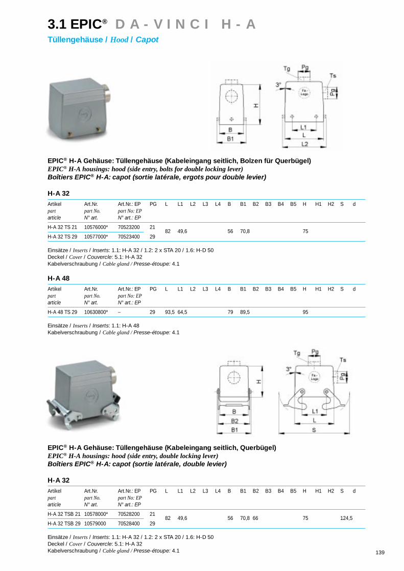
139
EPIC® H-A Gehäuse: Tüllengehäuse (Kabeleingang seitlich, Bolzen für Querbügel)EPIC® H-A housings: hood (side entry, bolts for double locking lever)Boîtiers EPIC® H-A: capot (sortie latérale, ergots pour double levier)
H-A 32
Artikel Art.Nr. Art.Nr.: EP PG L L1 L2 L3 L4 B B1 B2 B3 B4 B5 H H1 H2 S dpart part No. part No: EParticle N° art. N° art.: EP
H-A 32 TS 21 10576000* 70523200 21
H-A 32 TS 29 10577000* 70523400 2982 49,6 56 70,8 75
Einsätze / Inserts/ Inserts: 1.1: H-A 32 / 1.2: 2 x STA 20 / 1.6: H-D 50Deckel / Cover/ Couvercle: 5.1: H-A 32Kabelverschraubung / Cable gland / Presse-étoupe: 4.1
H-A 48
Artikel Art.Nr. Art.Nr.: EP PG L L1 L2 L3 L4 B B1 B2 B3 B4 B5 H H1 H2 S dpart part No. part No: EParticle N° art. N° art.: EP
H-A 48 TS 29 10630800* – 29 93,5 64,5 79 89,5 95
Einsätze / Inserts/ Inserts: 1.1: H-A 48Kabelverschraubung / Cable gland / Presse-étoupe: 4.1
EPIC® H-A Gehäuse: Tüllengehäuse (Kabeleingang seitlich, Querbügel)EPIC® H-A housings: hood (side entry, double locking lever)Boîtiers EPIC® H-A: capot (sortie latérale, double levier)
H-A 32
Artikel Art.Nr. Art.Nr.: EP PG L L1 L2 L3 L4 B B1 B2 B3 B4 B5 H H1 H2 S dpart part No. part No: EParticle N° art. N° art.: EP
H-A 32 TSB 21 10578000* 70528200 21
H-A 32 TSB 29 10579000 70528400 2982 49,6 56 70,8 66 75 124,5
Einsätze / Inserts/ Inserts: 1.1: H-A 32 / 1.2: 2 x STA 20 / 1.6: H-D 50Deckel / Cover/ Couvercle: 5.1: H-A 32Kabelverschraubung / Cable gland / Presse-étoupe: 4.1
3.1 EPIC® D A - V I N C I H - ATüllengehäuse / Hood / Capot

140
EPIC® H-A Gehäuse: AnbaugehäuseEPIC® H-A housings: panel mount baseBoîtiers EPIC® H-A: embase encastrée
H-A 3
Artikel Art.Nr. PG Material Farbe Verschraubung B Hpart part No. material colour cable glandarticle N° art. matière couleur presse-étoupe
H-A 3 MAg 10422500* Zinkdruckguß / zinc die cast / zinc moulé par injection grau/grey/grise
H-A 3 Ag 10422200* Thermoplast / thermoplastic / plastique thermoformé schwarz/black/noir
H-A 3 Ag 10422000* Thermoplast / thermoplastic / plastique thermoformé grau/grey/grise
Einsätze / Inserts/ Inserts: 1.1: H-A 3, H-A 4 / 1.2: STA 6 / 1.6: H-D 7, H-D 8Deckel / Cover/ Couvercle: 5.1: H-A 3
EPIC® H-A Gehäuse: Anbaugehäuse (gewinkelt)EPIC® H-A housings: panel mount base (angled)Boîtiers EPIC® H-A: embase encastrée (sortie latérale)
H-A 3
Artikel Art.Nr. PG Material Farbe Verschraubung B Hpart part No. material colour cable glandarticle N° art. matière couleur presse-étoupe
H-A 3 MAgs 10423500* Zinkdruckguß / zinc die cast / zinc moulé par injection grau/grey/grise
H-A 3 Ags 10423100* Thermoplast / thermoplastic / plastique thermoformé schwarz/black/noir
H-A 3 Ags 10423000* Thermoplast / thermoplastic / plastique thermoformé grau/grey/grise
Einsätze / Inserts/ Inserts: 1.1: H-A 3, H-A 4 / 1.2: STA 6 / 1.6: H-D 7, H-D 8Deckel / Cover/ Couvercle: 5.1: H-A 3
3.1 EPIC® D A - V I N C I H - AAnbaugehäuse / Panel mount base/ Embase encastrée

141
EPIC® H-A Gehäuse: Anbaugehäuse (Längsbügel)EPIC® H-A housings: panel mount base (single locking lever)Boîtiers EPIC® H-A: embase encastrée (simple levier)
H-A 10
Artikel Art.Nr. Art.Nr.: EP PG L L1 L2 L3 L4 B B1 B2 B3 B4 B5 H H1 H2 S dpart part No. part No: EParticle N° art. N° art.: EP
H-A 10 AG-LB 10442000* 70442500 63 74,4 71,4 70 81 29,5 17,5 25 3,5 36,5 3,6
Einsätze / Inserts/ Inserts: 1.1: H-A 10 / 1.2: STA 14 / 1.6: H-D 15Deckel / Cover/ Couvercle: 5.1: H-A 10
H-A 16
Artikel Art.Nr. Art.Nr.: EP PG L L1 L2 L3 L4 B B1 B2 B3 B4 B5 H H1 H2 S dpart part No. part No: EParticle N° art. N° art.: EP
H-A 16 AG-LB 10462000* 70472500 79 90,4 87,8 86 96 29,5 17,5 25 3,5 36,5 3,6
Einsätze / Inserts/ Inserts: 1.1:H-A 16 / 1.2: STA 20 / 1.6: H-D 25Deckel / Cover/ Couvercle: 5.1: H-A 16
EPIC® H-A Gehäuse: Anbaugehäuse (Querbügel)EPIC® H-A housings: panel mount base (double locking lever)Boîtiers EPIC® H-A: embase encastrée (double levier)
H-A 32
Artikel Art.Nr. Art.Nr.: EP PG L L1 L2 L3 L4 B B1 B2 B3 B4 B5 H H1 H2 S dpart part No. part No: EParticle N° art. N° art.: EP
H-A 32 AG 10472000* 70502500 82 49,6 92 102 56 70,8 66 42 25,4 4 124,5 4,3
Einsätze / Inserts/ Inserts: 1.1: H-A 32 / 1.2: 2 x STA 20 / 1.6: H-D 50Deckel / Cover/ Couvercle: 5.1: H-A 32
H-A 48
Artikel Art.Nr. Art.Nr.: EP PG L L1 L2 L3 L4 B B1 B2 B3 B4 B5 H H1 H2 S dpart part No. part No: EParticle N° art. N° art.: EP
H-A 48 AG 10625500* – 93,5 64,5 110 124 79 93,8 87,8 65 30,3 5 136,5 5,5
Einsätze / Inserts/ Inserts: 1.1:H-A 48
3.1 EPIC® D A - V I N C I H - AAnbaugehäuse / Panel mount base/ Embase encastrée

142
EPIC® H-A Gehäuse: Anbaugehäuse (Schutzdeckel, Längsbügel)EPIC® H-A housings: panel mount base (cover, single locking lever)Boîtiers EPIC® H-A: embase encastrée (couvercle, simple levier)
H-A 10
Artikel Art.Nr. Art.Nr.: EP PG L L1 L2 L3 L4 B B1 B2 B3 B4 B5 H H1 H2 S dpart part No. part No: EParticle N° art. N° art.: EP
H-A 10 AD-LB 70444000 70444500 63 74,4 71,4 70 81 29,5 17,5 25 25 3,5 36,5 3,6
Einsätze / Inserts/ Inserts: 1.1: H-A 10 / 1.2: STA 14 / 1.6: H-D 15
H-A 16
Artikel Art.Nr. Art.Nr.: EP PG L L1 L2 L3 L4 B B1 B2 B3 B4 B5 H H1 H2 S dpart part No. part No: EParticle N° art. N° art.: EP
H-A 16 AD-LB 70474000 70474500 79 90,4 87,5 86 96 29,5 17,5 25 25 3,5 36,5 3,6
Einsätze / Inserts/ Inserts: 1.1:H-A 16 / 1.2: STA 20 / 1.6: H-D 25
EPIC® H-A Gehäuse: Anbaugehäuse (Schutzdeckel, Bolzen für Querbügel)EPIC® H-A housings: panel mount base (cover, bolts for double locking lever)Boîtiers EPIC® H-A: embase encastrée (couvercle, ergots pour double levier)
H-A 32
Artikel Art.Nr. Art.Nr.: EP PG L L1 L2 L3 L4 B B1 B2 B3 B4 B5 H H1 H2 S dpart part No. part No: EParticle N° art. N° art.: EP
H-A 32 AD-BO 70503000 70503500 82 49,6 92 102 56 42 29 25,4 4 4,3
Einsätze / Inserts/ Inserts: 1.1: H-A 32 / 1.2: 2 x STA 20 / 1.6: H-D 50
3.1 EPIC® D A - V I N C I H - AAnbaugehäuse / Panel mount base/ Embase encastrée

143
EPIC® H-A Gehäuse: SockelgehäuseEPIC® H-A housings: surface mount baseBoîtiers EPIC® H-A: embase en saillie
H-A 3
Artikel Art.Nr. PG Material Farbe Verschraubung B Hpart part No. material colour cable glandarticle N° art. matière couleur presse-étoupe
H-A 3 MAgsv 10512700 11 Zinkdruckguß / zinc die cast / zinc moulé par injection grau/grey/grise 51,5
H-A 3 Agsv 10511700 11 Thermoplast / thermoplastic / plastique thermoformé schwarz/black/noir 56
H-A 3 Agsv 10424000* 11 Thermoplast / thermoplastic / plastique thermoformé grau/grey/grise 56
H-A 3 MAgsv 10424500* 11 Zinkdruckguß / zinc die cast / zinc moulé par injection grau/grey/grise 57,5
H-A 3 Agsv 10424700 11 Thermoplast / thermoplastic / plastique thermoformé schwarz/black/noir 65
H-A 3 Agsv 10424200 11 Thermoplast / thermoplastic / plastique thermoformé grau/grey/grise 65
Einsätze / Inserts/ Inserts: 1.1: H-A 3, H-A 4 / 1.2: STA 6 / 1.6: H-D 7, H-D 8Deckel / Cover/ Couvercle: 5.1: H-A 3Kabelverschraubung / Cable gland / Presse-étoupe: 4.1
3.1 EPIC® D A - V I N C I H - ASockelgehäuse / Surface mount base/ Embase en saillie

144
EPIC® H-A Gehäuse: Sockelgehäuse (1 Kabeleingang, Längsbügel)EPIC® H-A housings: surface mount base (1 cable entry , single locking lever)Boîtiers EPIC® H-A: embase en saillie (1 entrée de câble, simple levier)
H-A 10
Artikel Art.Nr. Art.Nr.: EP PG L L1 L2 L3 L4 B B1 B2 B3 B4 B5 H H1 H2 S dpart part No. part No: EParticle N° art. N° art.: EP
H-A 10 SGR-LB 16 10448100* 70447200 16
H-A 10 SGR-LB 21 10448000* 70447400 2163 74,4 71,4 48 80 29,5 40 50 57 3,5 36,5 4,5
Einsätze / Inserts/ Inserts: 1.1: H-A 10 / 1.2: STA 14 / 1.6: H-D 15Deckel / Cover/ Couvercle: 5.1: H-A 10Kabelverschraubung / Cable gland / Presse-étoupe: 4.1
H-A 16
Artikel Art.Nr. Art.Nr.: EP PG L L1 L2 L3 L4 B B1 B2 B3 B4 B5 H H1 H2 S dpart part No. part No: EParticle N° art. N° art.: EP
H-A 16 SGR-LB 16 10567100* 70477200 16
H-A 16 SGR-LB 21 10567000* 70477400 2179 90,4 87,8 64 96 29,5 40 50 57 3,5 36,5 4,5
Einsätze / Inserts/ Inserts: 1.1: H-A 16 / 1.2: STA 20 / 1.6: H-D 25Deckel / Cover/ Couvercle: 5.1: H-A 16Kabelverschraubung / Cable gland / Presse-étoupe: 4.1
EPIC® H-A Gehäuse: Sockelgehäuse (2 Kabeleingänge, Längsbügel)EPIC® H-A housings: surface mount base (2 cable entries, single locking lever)Boîtiers EPIC® H-A: embase à encastrer (2 entrées de câble, simple levier)
H-A 10
Artikel Art.Nr. Art.Nr.: EP PG L L1 L2 L3 L4 B B1 B2 B3 B4 B5 H H1 H2 S dpart part No. part No: EParticle N° art. N° art.: EP
H-A 10 SGRL-LB 16 10450100* 70448200 16
H-A 10 SGRL-LB 21 10450000* 70448400 2163 74,4 71,4 48 80 29,5 40 50 57 3,5 36,5 4,5
Einsätze / Inserts/ Inserts: 1.1: H-A 10 / 1.2: STA 14 / 1.6: H-D 15Deckel / Cover/ Couvercle: 5.1: H-A 10Kabelverschraubung / Cable gland / Presse-étoupe: 4.1
H-A 16
Artikel Art.Nr. Art.Nr.: EP PG L L1 L2 L3 L4 B B1 B2 B3 B4 B5 H H1 H2 S dpart part No. part No: EParticle N° art. N° art.: EP
H-A 16 SGRL-LB 16 10568100* 70478200 16
H-A 16 SGRL-LB 21 10568000 70478400 2179 90,4 87,8 64 96 29,5 40 50 57 3,5 36,5 4,5
Einsätze / Inserts/ Inserts: 1.1: H-A 16 / 1.2: STA 20 / 1.6: H-D 25Deckel / Cover/ Couvercle: 5.1: H-A 16Kabelverschraubung / Cable gland / Presse-étoupe: 4.1
3.1 EPIC® D A - V I N C I H - ASockelgehäuse / Surface mount base/ Embase en saillie

145
EPIC® H-A Gehäuse: Sockelgehäuse (1 Kabeleingang, Querbügel)EPIC® H-A housings: surface mount base (1 cable entry, double locking lever)Boîtiers EPIC® H-A: embase en saillie (1 entrée de câble, double levier)
H-A 32
Artikel Art.Nr. Art.Nr.: EP PG L L1 L2 L3 L4 B B1 B2 B3 B4 B5 H H1 H2 S dpart part No. part No: EParticle N° art. N° art.: EP
H-A 32 SGR 21 10474000* 70507200 21
H-A 32 SGR 29 10474100* 70507400 2982 49,6 94 106 56 70,8 66 46 57 75 4 124,5 5,5
Einsätze / Inserts/ Inserts: 1.1: H-A 32 / 1.2: 2 x STA 20 / 1.6: H-D 50Deckel / Cover/ Couvercle: 5.1: H-A 32Kabelverschraubung / Cable gland / Presse-étoupe: 4.1
H-A 48
Artikel Art.Nr. Art.Nr.: EP PG L L1 L2 L3 L4 B B1 B2 B3 B4 B5 H H1 H2 S dpart part No. part No: EParticle N° art. N° art.: EP
H-A 48 SGR 29 10633800 – 29 93,5 64,5 112 124,5 79 93,8 87,8 67 81 72 5 136,5 5,5
Einsätze / Inserts/ Inserts: 1.1: H-A 48Kabelverschraubung / Cable gland / Presse-étoupe: 4.1
3.1 EPIC® D A - V I N C I H - ASockelgehäuse / Surface mount base/ Embase en saillie

146
EPIC® H-A Gehäuse: Sockelgehäuse (2 Kabeleingänge, Querbügel)EPIC® H-A housings: surface mount base (2 cable entries, double locking lever)Boîtiers EPIC® H-A: embase en saillie (2 entrées de câble, double levier)
H-A 32
Artikel Art.Nr. Art.Nr.: EP PG L L1 L2 L3 L4 B B1 B2 B3 B4 B5 H H1 H2 S dpart part No. part No: EParticle N° art. N° art.: EP
H-A 32 SGRL21 10482000 70508200 21
H-A 32 SGRL 29 10482100 70508400 2982 49,6 94 106 56 70,8 66 46 57 75 4 124,5 5,5
Einsätze / Inserts/ Inserts: 1.1: H-A 32 / 1.2: 2 x STA 20 / 1.6: H-D 50Deckel / Cover/ Couvercle: 5.1: H-A 32Kabelverschraubung / Cable gland / Presse-étoupe: 4.1
H-A 48
Artikel Art.Nr. Art.Nr.: EP PG L L1 L2 L3 L4 B B1 B2 B3 B4 B5 H H1 H2 S dpart part No. part No: EParticle N° art. N° art.: EP
H-A 48 SGRL 29 10634800 – 29 93,5 64,5 112 124,5 79 93,8 87,8 67 81 72 5 136,5 5,5
Einsätze / Inserts/ Inserts: 1.1: H-A 48Kabelverschraubung / Cable gland / Presse-étoupe: 4.1
3.1 EPIC® D A - V I N C I H - ASockelgehäuse / Surface mount base/ Embase en saillie

147
EPIC® H-A Gehäuse: Sockelgehäuse (Schutzdeckel, 1 Kabeleingang, Längsbügel)EPIC® H-A housings: surface mount base (cover, 1 cable entry, single locking lever)Boîtiers EPIC® H-A: embase en saillie (couvercle, 1 entrée de câble, simple levier)
H-A 10
Artikel Art.Nr. Art.Nr.: EP PG L L1 L2 L3 L4 B B1 B2 B3 B4 B5 H H1 H2 S dpart part No. part No: EParticle N° art. N° art.: EP
H-A 10 SDR-LB 16 70455200 70457200 16
H-A 10 SDR-LB 21 70455400 70457400 2163 74,4 71,4 48 80 29,5 40 50 25 57 3,5 36,5 4,5
Einsätze / Inserts/ Inserts: 1.1: H-A 10 / 1.2: STA 14 / 1.6: H-D 15Kabelverschraubung / Cable gland / Presse-étoupe: 4.1
H-A 16
Artikel Art.Nr. Art.Nr.: EP PG L L1 L2 L3 L4 B B1 B2 B3 B4 B5 H H1 H2 S dpart part No. part No: EParticle N° art. N° art.: EP
H-A 16 SDR-LB 16 70485200 70487200 16
H-A 16 SDR-LB 21 70485400 70487400 2179 90,4 87,8 64 96 29,5 40 50 25 57 3,5 36,5 4,5
Einsätze / Inserts/ Inserts: 1.1: H-A 16 / 1.2: STA 20 / 1.6: H-D 25Kabelverschraubung / Cable gland / Presse-étoupe: 4.1
EPIC® H-A Gehäuse: Sockelgehäuse (Schutzdeckel, 2 Kabeleingänge, Längsbügel)EPIC® H-A housings: surface mount base (cover, 2 cable entries, single locking lever)Boîtiers EPIC® H-A: embase en saillie (couvercle, 2 entrées de câble, simple levier)
H-A 10
Artikel Art.Nr. Art.Nr.: EP PG L L1 L2 L3 L4 B B1 B2 B3 B4 B5 H H1 H2 S dpart part No. part No: EParticle N° art. N° art.: EP
H-A 10 SDRL-LB 16 70456200 70458200 16
H-A 10 SDRL-LB 21 70456400 70458400 2163 74,4 71,4 48 80 29,5 40 50 25 57 3,5 36,5 4,5
Einsätze / Inserts/ Inserts: 1.1: H-A 10 / 1.2: STA 14 / 1.6: H-D 15Kabelverschraubung / Cable gland / Presse-étoupe: 4.1
H-A 16
Artikel Art.Nr. Art.Nr.: EP PG L L1 L2 L3 L4 B B1 B2 B3 B4 B5 H H1 H2 S dpart part No. part No: EParticle N° art. N° art.: EP
H-A 16 SDRL-LB 16 70486200 70488200 16
H-A 16 SDRL-LB 21 70486400 70488400 2179 90,4 87,8 64 96 29,5 40 50 25 57 3,5 36,5 4,5
Einsätze / Inserts/ Inserts: 1.1: H-A 16 / 1.2: STA 20 / 1.6: H-D 25Kabelverschraubung / Cable gland / Presse-étoupe: 4.1
3.1 EPIC® D A - V I N C I H - ASockelgehäuse / Surface mount base/ Embase en saillie

148
EPIC® H-A Gehäuse: Sockelgehäuse (Schutzdeckel, 1 Kabeleingang, Bolzen für Querbügel)EPIC® H-A housings: surface mount base (cover, 1 cable entry, bolts for double locking lever)Boîtiers EPIC® H-A: embase en saillie (couvercle, 1 entrée de câble, ergots pour double levier)
H-A 32
Artikel Art.Nr. Art.Nr.: EP PG L L1 L2 L3 L4 B B1 B2 B3 B4 B5 H H1 H2 S dpart part No. part No: EParticle N° art. N° art.: EP
H-A 32 SDR-BO 21 70515200 70517200 21
H-A 32 SDR-BO 29 70515400 70517400 2982 49,6 94 106 56 70,8 46 57 29 75 4 5,5
Einsätze / Inserts/ Inserts: 1.1: H-A 32 / 1.2: 2 x STA 20 / 1.6: H-D 50Kabelverschraubung / Cable gland / Presse-étoupe: 4.1
EPIC® H-A Gehäuse: Sockelgehäuse (Schutzdeckel, 2 Kabeleingänge, Bolzen für Querbügel)EPIC® H-A housings: surface mount base (cover, 2 cable entries, bolts for double locking lever)Boîtiers EPIC® H-A: embase en saillie (couvercle, 2 entrées de câble, ergots pour double levier)
H-A 32
Artikel Art.Nr. Art.Nr.: EP PG L L1 L2 L3 L4 B B1 B2 B3 B4 B5 H H1 H2 S dpart part No. part No: EParticle N° art. N° art.: EP
H-A 32 SDRL-BO 21 70516200 70518200 21
H-A 32 SDRL-BO 29 70516400 70518400 2982 49,6 94 106 56 70,8 46 57 29 75 4 5,5
Einsätze / Inserts/ Inserts: 1.1: H-A 32 / 1.2: STA 20 / 1.6: H-D 50Kabelverschraubung / Cable gland / Presse-étoupe: 4.1
3.1 EPIC® D A - V I N C I H - ASockelgehäuse / Surface mount base/ Embase en saillie
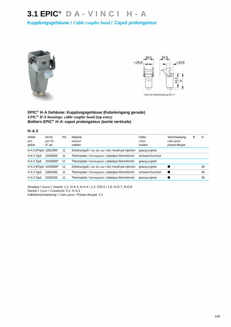
149
EPIC® H-A Gehäuse: Kupplungsgehäuse (Kabeleingang gerade)EPIC® H-A housings: cable coupler hood (top entry)Boîtiers EPIC® H-A: capot prolongateur (sortie verticale)
H-A 3
Artikel Art.Nr. PG Material Farbe Verschraubung B Hpart part No. material colour cable glandarticle N° art. matière couleur presse-étoupe
H-A 3 MTgvb 10512900 11 Zinkdruckguß / zinc die cast / zinc moulé par injection grau/grey/grise
H-A 3 Tgvb 10429200 11 Thermoplast / thermoplastic / plastique thermoformé schwarz/black/noir
H-A 3 Tgvb 10429000* 11 Thermoplast / thermoplastic / plastique thermoformé grau/grey/grise
H-A 3 MTgvb 10429500* 11 Zinkdruckguß / zinc die cast / zinc moulé par injection grau/grey/grise 60
H-A 3 Tgvb 10620300 11 Thermoplast / thermoplastic / plastique thermoformé schwarz/black/noir 65
H-A 3 Tgvb 10429100 11 Thermoplast / thermoplastic / plastique thermoformé grau/grey/grise 65
Einsätze / Inserts/ Inserts: 1.1: H-A 3, H-A 4 / 1.2: STA 6 / 1.6: H-D 7, H-D 8Deckel / Cover/ Couvercle: 5.1: H-A 3Kabelverschraubung / Cable gland / Presse-étoupe: 4.1
3.1 EPIC® D A - V I N C I H - AKupplungsgehäuse / Cable coupler hood/ Capot prolongateur

150
EPIC® H-A Gehäuse: Kupplungsgehäuse (Kabeleingang gerade, Längsbügel)EPIC® H-A housings: cable coupler hood (top entry, single locking lever)Boîtiers EPIC® H-A: capot prolongateur (sortie verticale, simple levier)
H-A 10
Artikel Art.Nr. Art.Nr.: EP PG L L1 L2 L3 L4 B B1 B2 B3 B4 B5 H H1 H2 S dpart part No. part No: EParticle N° art. N° art.: EP
H-A 10 TBF-LB 13,5 10439000*
H-A 10 TBF-LB 16 70450000 7045100016 63 74,4 71,4 29,5 48 36,5
Einsätze / Inserts/ Inserts: 1.1: H-A 10 / 1.2: STA 14 / 1.6: H-D 15Deckel / Cover/ Couvercle: 5.1: H-A 10Kabelverschraubung / Cable gland / Presse-étoupe: 4.1
H-A 16
Artikel Art.Nr. Art.Nr.: EP PG L L1 L2 L3 L4 B B1 B2 B3 B4 B5 H H1 H2 S dpart part No. part No: EParticle N° art. N° art.: EP
H-A 16 TBF-LB 16 10563000 70481000 16 79 90,4 87,8 29,5 53 36,5
Einsätze / Inserts/ Inserts: 1.1: H-A 16 / 1.2: STA 20 / 1.6: H-D 25Deckel / Cover/ Couvercle: 5.1: H-A 16Kabelverschraubung / Cable gland / Presse-étoupe: 4.1
EPIC® H-A Gehäuse: Kupplungsgehäuse (Kabeleingang gerade, Längsbügel, hohe Bauform)EPIC® H-A housings: cable coupler hood (top entry, single locking lever, high version)Boîtiers EPIC® H-A: capot prolongateur (sortie verticale, simple levier, version haute)
H-A 10
Artikel Art.Nr. Art.Nr.: EP PG L L1 L2 L3 L4 B B1 B2 B3 B4 B5 H H1 H2 S dpart part No. part No: EParticle N° art. N° art.: EP
H-A 10 TBFH-LB 21 70450400 70451400 21 63 74,4 71,4 29,5 62 36,5
Einsätze / Inserts/ Inserts: 1.1: H-A 10 / 1.2: STA 14 / 1.6: H-D 15Deckel / Cover/ Couvercle: 5.1: H-A 10Kabelverschraubung / Cable gland / Presse-étoupe: 4.1
H-A 16
Artikel Art.Nr. Art.Nr.: EP PG L L1 L2 L3 L4 B B1 B2 B3 B4 B5 H H1 H2 S dpart part No. part No: EParticle N° art. N° art.: EP
H-A 16 TBFH-LB 16 70480200 70481200 16
H-A 16 TBFH-LB 21 70480400 70481400 2179 90,4 87,8 29,5 67 36,5
Einsätze / Inserts/ Inserts: 1.1: H-A 16 / 1.2: STA 20 / 1.6: H-D 25Deckel / Cover/ Couvercle: 5.1: H-A 16Kabelverschraubung / Cable gland / Presse-étoupe: 4.1
3.1 EPIC® D A - V I N C I H - AKupplungsgehäuse / Cable coupler hood/ Capot prolongateur

151
EPIC® H-A Gehäuse: Kupplungsgehäuse (Kabeleingang gerade, Querbügel)EPIC® H-A housings: cable coupler hood (top entry, double locking lever)Boîtiers EPIC® H-A: capot prolongateur (sortie verticale, double levier)
H-A 32
Artikel Art.Nr. Art.Nr.: EP PG L L1 L2 L3 L4 B B1 B2 B3 B4 B5 H H1 H2 S dpart part No. part No: EParticle N° art. N° art.: EP
H-A 32 TBF 21 10588000 70511000 21
H-A 32 TBF 29 10588500 70511200 2982 49,6 56 70,8 66 76,5 124,5
Einsätze / Inserts/ Inserts: 1.1: H-A 32 / 1.2: 2 x STA 20 / 1.6: H-D 50Deckel / Cover/ Couvercle: 5.1: H-A 32Kabelverschraubung / Cable gland / Presse-étoupe: 4.1
3.1 EPIC® D A - V I N C I H - AKupplungsgehäuse / Cable coupler hood/ Capot prolongateur

153
Solide Bauform und ein umfangreiches Pro-
gramm an passenden Einsätzen sind die mar-
kanten Merkmale dieses Gehäuses. Diese
Bauform läßt sich aus dem aus dem Industrie-
standard nicht mehr wegdenken. Die Gehäuse
der H-B Serie gibt es in sechs verschiedenen
Gehäusegrößen.
The striking characteristics of these mount ba-
ses are a sturdy construction and a compre-
hensive range of corresponding inserts. This
style is used in all industrial applications. The
H-B series housings are available in six diffe-
rent sizes.
Une forme de construction solide et un pro-
gramme important d’inserts adéquats sont les
caractéristiques marquantes de ce boîtier. Cet-
te forme de construction est devenue indi-
spensable au standard industriel. Les boîtiers
de la série H-B sont disponibles en six tailles
différentes.
3.2 EPIC® D A - V I N C I H - BTüllengehäuse / Hood / Capot

154
Technische Daten:Vorschriften: DIN 43652Temperaturbereich: -40°C - +125°CSchutzart: IP 65Werkstoff: H-B 6 – 48: Aluminiumlegierung, pulverbeschichtet
Technical DataSpecifications: DIN 43652Temperature range: : -40°C - +125°CProtection class: IP 65Material: H-B 6 – 48: aluminium alloy, powder coated
Caractéristiques techniquesRéglements: DIN 43652Gamme de température: : -40°C - +125°CDegré de protection: IP 65Matière: H-B 6 – 48: Alliage aluminium, recouvert par pulvérisation
EPIC®
Aluminiumlegierung, pulverbeschichtet (grau), Bügel und Bolzen aus verzinktem StahlAluminium alloy, powder coated (grey), locking levers and bolts made of zinc plated steelAlliage aluminium, recouvert par pulvérisation (grise), leviers et ergots acier recouvert par zinc
Für den industriellen Einsatz in anspruchsvoller Umgebung.For industrial applications in demanding environments.Pour une exploitation industrielle dans un environnement exigeant.
EPIC® EP: (Environmental Protected)Aluminiumlegierung, pulverbeschichtet (schwarz), Bügel und Bolzen aus EdelstahlAluminium alloy, powder coated (black), locking levers and bolts made of stainless steelAlliage aluminium, recouvert par pulvérisation (noir), leviers et ergots acier inox
Für den industriellen Einsatz in stark beanspruchter Umgebung mit aggressiver Atmosphäre.For industrial applications in extremely demanding environments with aggressive atmospheres.Pour l’exploitation industrielle dans un environnement très sollicité à atmosphère agressive.
EPIC® EcoAluminiumlegierung, unbeschichtet, Bügel und Bolzen aus verzinktem Stahl Aluminium alloy, uncoated, locking levers and bolts made of zinc plated steelAlliage aluminium, sans pulvérisation, leviers et ergots acier recouvert par zinc
EMV - geschützt. Für den industriellen Einsatz in anspruchsvoller Umgebung.EMC-protected for industrial applications in demanding environments.Protection CEM. Pour une exploitation industrielle dans un environnement exigeant.
3.2 EPIC® D A - V I N C I H - BTüllengehäuse / Hood / Capot

155
3.2 EPIC® D A - V I N C I H - BTüllengehäuse / Hood / Capot
EPIC® H-B Gehäuse: Tüllengehäuse (Kabeleingang gerade, Bolzen für Längsbügel)EPIC® H-B housings: hood (top entry, bolts for single locking lever)Boîtiers EPIC® H-B: capot (sortie verticale, ergots pour simple levier)
H-B 6
Artikel Art.Nr. Art.Nr.: EP PG L L1 L2 L3 L4 B B1 B2 B3 B4 B5 H H1 H2 S dpart part No. part No: EParticle N° art. N° art.: EP
H-B 6 TG 13,5 10011000* 70021600 13,5
H-B 6 TG 16 10021000* 70021000 1660 74,8 43 52
Einsätze / Inserts/ Inserts: 1.3: H-BE 6 / 1.7: H-DD 24 / 1.8: MC 6Deckel / Cover/ Couvercle: 5.1: H-BE 6Kabelverschraubung / Cable gland / Presse-étoupe: 4.1
H-B 10
Artikel Art.Nr. Art.Nr.: EP PG L L1 L2 L3 L4 B B1 B2 B3 B4 B5 H H1 H2 S dpart part No. part No: EParticle N° art. N° art.: EP
H-B 10 TG-RO 16 10040900* 70049000 16
H-B 10 TG-RO 21 10040700 70049600 2173 90 43 52
Einsätze / Inserts/ Inserts: 1.3: H-BE 10 / 1.5: H-BVE 3 / 1.7: H-DD 42 / 1.8: MC 10Kabelverschraubung / Cable gland / Presse-étoupe: 4.1
H-B 16
Artikel Art.Nr. Art.Nr.: EP PG L L1 L2 L3 L4 B B1 B2 B3 B4 B5 H H1 H2 S dpart part No. part No: EParticle N° art. N° art.: EP
H-B 16 TG-RO 21 10080900* 70099000 21 93,3 110 43 61
Einsätze / Inserts/ Inserts: 1.3: H-BE 16 / 1.4: H-BS 6 / 1.5: H-BVE 6 / 1.6: H-D 40 / 1.7: H-DD 72 / 1.8: MC 16Kabelverschraubung / Cable gland / Presse-étoupe: 4.1
H-B 24
Artikel Art.Nr. Art.Nr.: EP PG L L1 L2 L3 L4 B B1 B2 B3 B4 B5 H H1 H2 S dpart part No. part No: EParticle N° art. N° art.: EP
H-B 24 TG-RO 21 10121900* 70149000 21
H-B 24 TG-RO 29 10111900* 70149200 29120 137 43 61
Einsätze / Inserts/ Inserts: 1.3: H-BE 48 / 1.5: H-BVE 10 / 1.6: H-D 64 / 1.7: H-DD 108 / 1.8: MC 24Kabelverschraubung / Cable gland / Presse-étoupe: 4.1
H-B 48
Artikel Art.Nr. Art.Nr.: EP PG L L1 L2 L3 L4 B B1 B2 B3 B4 B5 H H1 H2 S dpart part No. part No: EParticle N° art. N° art.: EP
H-B 48 TG 29 10155000* – 29
H-B 48 TG 36 10156000* – 36 132 152 90 105
H-B 48 TG 42 10157000* – 42
Einsätze / Inserts/ Inserts: 1.3: H-BE 48 / 1.5: 2 x H-BVE 10 / 1.6: H-D 128 / 1.7: H-DD 216 / 1.8: 2 x MC 24Kabelverschraubung / Cable gland / Presse-étoupe: 4.1

156
3.2 EPIC® D A - V I N C I H - BTüllengehäuse / Hood / Capot
EPIC® H-B Gehäuse: Tüllengehäuse (Kabeleingang gerade, Bolzen für Längsbügel, hohe Bauform)EPIC® H-B housings: hood (top entry, bolts for single locking lever, high version)Boîtiers EPIC® H-B: capot (sortie verticale, ergots pour simple levier, version haute)
H-B 6
Artikel Art.Nr. Art.Nr.: EP PG L L1 L2 L3 L4 B B1 B2 B3 B4 B5 H H1 H2 S dpart part No. part No: EParticle N° art. N° art.: EP
H-B 6 TGH 21 70020200 70021200 21
H-B 6 TGH 29 70020400 70021400 2960 74,8 43 72
Einsätze / Inserts/ Inserts: 1.3: H-BE 6 / 1.7: H-DD 24 / 1.8: MC 6Deckel / Cover/ Couvercle: 5.1: H-B 6Kabelverschraubung / Cable gland / Presse-étoupe: 4.1
H-B 10
Artikel Art.Nr. Art.Nr.: EP PG L L1 L2 L3 L4 B B1 B2 B3 B4 B5 H H1 H2 S dpart part No. part No: EParticle N° art. N° art.: EP
H-B 10 TGH-RO 21 70044200 70049200 21
H-B 10 TGH-RO 29 70044400 70049400 2973 90 43 72
Einsätze / Inserts/ Inserts: 1.3: H-BE 10 / 1.5: H-BVE 3 / 1.7: H-DD 42 / 1.8: MC 10Kabelverschraubung / Cable gland / Presse-étoupe: 4.1
H-B 16
Artikel Art.Nr. Art.Nr.: EP PG L L1 L2 L3 L4 B B1 B2 B3 B4 B5 H H1 H2 S dpart part No. part No: EParticle N° art. N° art.: EP
H-B 16 TGH-RO 21 70094200 70099200 21
H-B 16 TGH-RO 29 70094400 70099400 2993,3 110 43 76
Einsätze / Inserts/ Inserts: 1.3: H-BE 16 / 1.4: H-BS 6 / 1.5: H-BVE 6 / 1.6: H-D 40 / 1.7: H-DD 72 / 1.8: MC 16Kabelverschraubung / Cable gland / Presse-étoupe: 4.1
H-B 24
Artikel Art.Nr. Art.Nr.: EP PG L L1 L2 L3 L4 B B1 B2 B3 B4 B5 H H1 H2 S dpart part No. part No: EParticle N° art. N° art.: EP
H-B 24 TGH-RO 21 70144400 70149400 21
H-B 24 TGH-RO 29 70144600 70149600 29120 137 43 76
Einsätze / Inserts/ Inserts: 1.3: H-BE 24 / 1.5: H-BVE 10 / 1.6: H-D 64 / 1.7: H-DD 108 / 1.8: MC 24Kabelverschraubung / Cable gland / Presse-étoupe: 4.1

157
3.2 EPIC® D A - V I N C I H - BTüllengehäuse / Hood / Capot
EPIC® H-B Gehäuse: Tüllengehäuse (Kabeleingang seitlich, Bolzen für Längsbügel)EPIC® H-B housings: hood (side entry, bolts for single locking lever)Boîtiers EPIC® H-B: capot (sortie latérale, ergots pour simple levier)
H-B 6
Artikel Art.Nr. Art.Nr.: EP PG L L1 L2 L3 L4 B B1 B2 B3 B4 B5 H H1 H2 S dpart part No. part No: EParticle N° art. N° art.: EP
H-B 6 TS 13,5 10012000* 70023600 13,5
H-B 6 TS 16 10022000* 70023000 1660 74,8 43 52
Einsätze / Inserts/ Inserts: 1.3: H-BE 6 / 1.7: H-DD 24 / 1.8: MC 6Deckel / Cover/ Couvercle: 5.1: H-B 6Kabelverschraubung / Cable gland / Presse-étoupe: 4.1
H-B 10
Artikel Art.Nr. Art.Nr.: EP PG L L1 L2 L3 L4 B B1 B2 B3 B4 B5 H H1 H2 S dpart part No. part No: EParticle N° art. N° art.: EP
H-B 10 TS-RO 16 10042900* 70059000 16
H-B 10 TS-RO 21 10042800* 70059600 2173 90 43 52
Einsätze / Inserts/ Inserts: 1.3: H-BE 10 / 1.5: H-BVE 3 / 1.7: H-DD 42 / 1.8: MC 10Kabelverschraubung / Cable gland / Presse-étoupe: 4.1
H-B 16
Artikel Art.Nr. Art.Nr.: EP PG L L1 L2 L3 L4 B B1 B2 B3 B4 B5 H H1 H2 S dpart part No. part No: EParticle N° art. N° art.: EP
H-B 16 TS-RO 21 10082900* 70109000 21
H-B 16 TS-RO 29 10092900* 2993,3 110 43 61
Einsätze / Inserts/ Inserts: 1.3: H-BE 16 / 1.4: H-BS 6 / 1.5: H-BVE 6 / 1.6: H-D 40 / 1.7: H-DD 72 / 1.8: MC 16Kabelverschraubung / Cable gland / Presse-étoupe: 4.1
H-B 24
Artikel Art.Nr. Art.Nr.: EP PG L L1 L2 L3 L4 B B1 B2 B3 B4 B5 H H1 H2 S dpart part No. part No: EParticle N° art. N° art.: EP
H-B 24 TS-RO 21 10113900* 70159000 21
H-B 24 TS-RO 29 10123900* 70159200 29120 137 43 61
Einsätze / Inserts/ Inserts: 1.3: H-BE 24 / 1.5: H-BVE 10 / 1.6: H-D 64 / 1.7: H-DD 108 / 1.8: MC 24Kabelverschraubung / Cable gland / Presse-étoupe: 4.1
H-B 48
Artikel Art.Nr. Art.Nr.: EP PG L L1 L2 L3 L4 B B1 B2 B3 B4 B5 H H1 H2 S dpart part No. part No: EParticle N° art. N° art.: EP
H-B 48 TS 29 10158000* – 29
H-B 48 TS 36 10159000* – 36 132 152 90 105
H-B 48 TS 42 10160000 – 42
Einsätze / Inserts/ Inserts: 1.3: H-BE 48 / 1.5: 2 x H-BVE 10 / 1.6: H-D 128 / 1.7: H-DD 216 / 1.8: 2 x MC 24Kabelverschraubung / Cable gland / Presse-étoupe: 4.1

158
3.2 EPIC® D A - V I N C I H - BTüllengehäuse / Hood / Capot
EPIC® H-B Gehäuse: Tüllengehäuse (Kabeleingang seitlich, Bolzen für Längsbügel, hohe Bauform)EPIC® H-B housings: hood (side entry, bolts for single locking lever, high version)Boîtiers EPIC® H-B: capot (sortie latérale, ergots pour simple levier, version haute)
H-B 6
Artikel Art.Nr. Art.Nr.: EP PG L L1 L2 L3 L4 B B1 B2 B3 B4 B5 H H1 H2 S dpart part No. part No: EParticle N° art. N° art.: EP
H-B 6 TSH 21 70022200 70023200 21
H-B 6 TSH 29 70022400 70023400 2960 74,8 43 72
Einsätze / Inserts/ Inserts: 1.3: H-BE 6 / 1.7: H-DD 24 / 1.8: MC 6Deckel / Cover/ Couvercle: 5.1: H-B 6Kabelverschraubung / Cable gland / Presse-étoupe: 4.1
H-B 10
Artikel Art.Nr. Art.Nr.: EP PG L L1 L2 L3 L4 B B1 B2 B3 B4 B5 H H1 H2 S dpart part No. part No: EParticle N° art. N° art.: EP
H-B 10 TSH-RO 21 70054200 70059200 21
H-B 10 TSH-RO 29 70054400 70059400 2973 90 43 72
Einsätze / Inserts/ Inserts: 1.3: H-BE 10 / 1.5: H-BVE 3 / 1.7: H-DD 42 / 1.8: MC 10Kabelverschraubung / Cable gland / Presse-étoupe: 4.1
H-B 16
Artikel Art.Nr. Art.Nr.: EP PG L L1 L2 L3 L4 B B1 B2 B3 B4 B5 H H1 H2 S dpart part No. part No: EParticle N° art. N° art.: EP
H-B 16 TSH-RO 21 70104200 70109200 21
H-B 16 TSH-RO 29 70104400 70109400 2993,3 110 43 76
Einsätze / Inserts/ Inserts: 1.3: H-BE 16 / 1.4: H-BS 6 / 1.5: H-BVE 6 / 1.6: H-D 40 / 1.7: H-DD 72 / 1.8: MC 16Kabelverschraubung / Cable gland / Presse-étoupe: 4.1
H-B 24
Artikel Art.Nr. Art.Nr.: EP PG L L1 L2 L3 L4 B B1 B2 B3 B4 B5 H H1 H2 S dpart part No. part No: EParticle N° art. N° art.: EP
H-B 24 TSH-RO 21 70154400 70159400 21
H-B 24 TSH-RO 29 70154600 70159600 29120 137 43 76
Einsätze / Inserts/ Inserts: 1.3: H-BE 24 / 1.5: H-BVE 10 / 1.6: H-D 64 / 1.7: H-DD 108 / 1.8: MC 24Kabelverschraubung / Cable gland / Presse-étoupe: 4.1

159
3.2 EPIC® D A - V I N C I H - BTüllengehäuse / Hood / Capot
EPIC® H-B Gehäuse: Tüllengehäuse (Kabeleingang gerade, Bolzen für Querbügel)EPIC® H-B housings: hood (top entry, bolts for double locking lever)Boîtiers EPIC® H-B: capot (sortie verticale, ergots pour double levier)
H-B 10
Artikel Art.Nr. Art.Nr.: EP PG L L1 L2 L3 L4 B B1 B2 B3 B4 B5 H H1 H2 S dpart part No. part No: EParticle N° art. N° art.: EP
H-B 10 TG 16 10040000* 70051000 16
H-B 10 TG 21 10040100* 70051200 2173 27 43 57,8 52
Einsätze / Inserts/ Inserts: 1.3: H-BE 10 / 1.5: H-BVE 3 / 1.7: H-DD 42 / 1.8: MC 10Deckel / Cover/ Couvercle: 5.1: H-B 10Kabelverschraubung / Cable gland / Presse-étoupe: 4.1
H-B 16
Artikel Art.Nr. Art.Nr.: EP PG L L1 L2 L3 L4 B B1 B2 B3 B4 B5 H H1 H2 S dpart part No. part No: EParticle N° art. N° art.: EP
H-B 16 TG 21 10080000* 70101000 21
H-B 16 TG 29 10090000* – 2993,3 47,5 43 57,8 61
Einsätze / Inserts/ Inserts: 1.3: H-BE 16 / 1.4: H-BS 6 / 1.5: H-BVE 6 / 1.6: H-D 40 / 1.7: H-DD 72 / 1.8: MC 16Deckel / Cover/ Couvercle: 5.1: H-B 16Kabelverschraubung / Cable gland / Presse-étoupe: 4.1
H-B 24
Artikel Art.Nr. Art.Nr.: EP PG L L1 L2 L3 L4 B B1 B2 B3 B4 B5 H H1 H2 S dpart part No. part No: EParticle N° art. N° art.: EP
H-B 24 TG 21 10121000* 70151000 21
H-B 24 TG 29 10111000* 70151200 29120 74 43 57,8 61
Einsätze / Inserts/ Inserts: 1.3: H-BE 24 / 1.5: H-BVE 10 / 1.6: H-D 64 / 1.7: H-DD 108 / 1.8: MC 24Deckel / Cover/ Couvercle: 5.1: H-B 24Kabelverschraubung / Cable gland / Presse-étoupe: 4.1

160
3.2 EPIC® D A - V I N C I H - BTüllengehäuse / Hood / Capot
EPIC® H-B Gehäuse: Tüllengehäuse (Kabeleingang gerade, Bolzen für Querbügel, hohe Bauform)EPIC® H-B housings: hood (top entry, bolts for double locking lever, high version)Boîtiers EPIC® H-B: capot (sortie verticale, ergots pour double levier, version haute)
H-B 10
Artikel Art.Nr. Art.Nr.: EP PG L L1 L2 L3 L4 B B1 B2 B3 B4 B5 H H1 H2 S dpart part No. part No: EParticle N° art. N° art.: EP
H-B 10 TGH 21 70050400 70051400 21
H-B 10 TGH 29 70050600 70051600 2973 27 43 57,8 72
Einsätze / Inserts/ Inserts: 1.3: H-BE 10 / 1.5: H-BVE 3 / 1.7: H-DD 42 / 1.8: MC 10Deckel / Cover/ Couvercle: 5.1: H-B 10Kabelverschraubung / Cable gland / Presse-étoupe: 4.1
H-B 16
Artikel Art.Nr. Art.Nr.: EP PG L L1 L2 L3 L4 B B1 B2 B3 B4 B5 H H1 H2 S dpart part No. part No: EParticle N° art. N° art.: EP
H-B 16 TGH 21 70100200 70101200 21
H-B 16 TGH 29 70100400* 70101400 2993,3 47,5 43 57,8 76
Einsätze / Inserts/ Inserts: 1.3: H-BE 16 / 1.4: H-BS 6 / 1.5: H-BVE 6 / 1.6: H-D 40 / 1.7: H-DD 72 / 1.8: MC 16Deckel / Cover/ Couvercle: 5.1: H-B 16Kabelverschraubung / Cable gland / Presse-étoupe: 4.1
H-B 24
Artikel Art.Nr. Art.Nr.: EP PG L L1 L2 L3 L4 B B1 B2 B3 B4 B5 H H1 H2 S dpart part No. part No: EParticle N° art. N° art.: EP
H-B 24 TGH 21 70150400 70151400 21
H-B 24 TGH 29 70150600 70151600 29120 74 43 57,8 76
Einsätze / Inserts/ Inserts: 1.3: H-BE 24 / 1.5: H-BVE 10 / 1.6: H-D 64 / 1.7: H-DD 108 / 1.8: MC 24 / 1.9: TB-H-BE 21, TB-H-D 64Deckel / Cover/ Couvercle: 5.1: H-B 24Kabelverschraubung / Cable gland / Presse-étoupe: 4.1
H-B 32
Artikel Art.Nr. Art.Nr.: EP PG L L1 L2 L3 L4 B B1 B2 B3 B4 B5 H H1 H2 S dpart part No. part No: EParticle N° art. N° art.: EP
H-B 32 TG 29 10134000* – 29 93,5 64,5 79 89,5 95
Einsätze / Inserts/ Inserts: 1.3: H-BE 32 / 1.4: H-BS 12 / 1.6: H-D 80 / 1.7: H-DD 144 / 1.8: 2 x MC 16Kabelverschraubung / Cable gland / Presse-étoupe: 4.1

161
3.2 EPIC® D A - V I N C I H - BTüllengehäuse / Hood / Capot
EPIC® H-B Gehäuse: Tüllengehäuse (Kabeleingang gerade, Querbügel)EPIC® H-B housings: hood (top entry, double locking lever)Boîtiers EPIC® H-B: capot (sortie verticale, double levier)
H-B 10
Artikel Art.Nr. Art.Nr.: EP PG L L1 L2 L3 L4 B B1 B2 B3 B4 B5 H H1 H2 S dpart part No. part No: EParticle N° art. N° art.: EP
H-B 10 TGB 16 10041000* 70056000 16 73 27 43 57,8 53 52 116
Einsätze / Inserts/ Inserts: 1.3: H-BE 10 / 1.5: H-BVE 3 / 1.7: H-DD 42 / 1.8: MC 10Deckel / Cover/ Couvercle: 5.1: H-B 10Kabelverschraubung / Cable gland / Presse-étoupe: 4.1
H-B 16
Artikel Art.Nr. Art.Nr.: EP PG L L1 L2 L3 L4 B B1 B2 B3 B4 B5 H H1 H2 S dpart part No. part No: EParticle N° art. N° art.: EP
H-B 16 TGB 21 10081000* 70106000 21 93,3 47,5 43 57,8 53 61 136,5
Einsätze / Inserts/ Inserts: 1.3: H-BE 16 / 1.4: H-BS 6 / 1.5: H-BVE 6 / 1.6: H-D 40 / 1.7: H-DD 72 / 1.8: MC 16Deckel / Cover/ Couvercle: 5.1: H-B 16Kabelverschraubung / Cable gland / Presse-étoupe: 4.1
H-B 24
Artikel Art.Nr. Art.Nr.: EP PG L L1 L2 L3 L4 B B1 B2 B3 B4 B5 H H1 H2 S dpart part No. part No: EParticle N° art. N° art.: EP
H-B 24 TGB 21 10122000 70156000 21
H-B 24 TGB 29 10112000* 70156200 29120 74 43 57,8 53 61 163
Einsätze / Inserts/ Inserts: 1.3: H-BE 24 / 1.5: H-BVE 10 / 1.6: H-D 64 / 1.7: H-DD 108 / 1.8: MC 24Deckel / Cover/ Couvercle: 5.1: H-B 24Kabelverschraubung / Cable gland / Presse-étoupe: 4.1
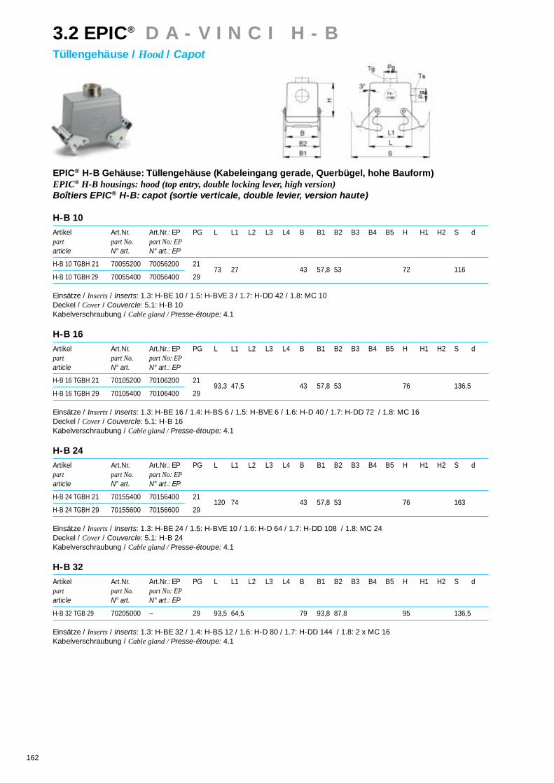
162
3.2 EPIC® D A - V I N C I H - BTüllengehäuse / Hood / Capot
EPIC® H-B Gehäuse: Tüllengehäuse (Kabeleingang gerade, Querbügel, hohe Bauform)EPIC® H-B housings: hood (top entry, double locking lever, high version)Boîtiers EPIC® H-B: capot (sortie verticale, double levier, version haute)
H-B 10
Artikel Art.Nr. Art.Nr.: EP PG L L1 L2 L3 L4 B B1 B2 B3 B4 B5 H H1 H2 S dpart part No. part No: EParticle N° art. N° art.: EP
H-B 10 TGBH 21 70055200 70056200 21
H-B 10 TGBH 29 70055400 70056400 2973 27 43 57,8 53 72 116
Einsätze / Inserts/ Inserts: 1.3: H-BE 10 / 1.5: H-BVE 3 / 1.7: H-DD 42 / 1.8: MC 10Deckel / Cover/ Couvercle: 5.1: H-B 10Kabelverschraubung / Cable gland / Presse-étoupe: 4.1
H-B 16
Artikel Art.Nr. Art.Nr.: EP PG L L1 L2 L3 L4 B B1 B2 B3 B4 B5 H H1 H2 S dpart part No. part No: EParticle N° art. N° art.: EP
H-B 16 TGBH 21 70105200 70106200 21
H-B 16 TGBH 29 70105400 70106400 2993,3 47,5 43 57,8 53 76 136,5
Einsätze / Inserts/ Inserts: 1.3: H-BE 16 / 1.4: H-BS 6 / 1.5: H-BVE 6 / 1.6: H-D 40 / 1.7: H-DD 72 / 1.8: MC 16Deckel / Cover/ Couvercle: 5.1: H-B 16Kabelverschraubung / Cable gland / Presse-étoupe: 4.1
H-B 24
Artikel Art.Nr. Art.Nr.: EP PG L L1 L2 L3 L4 B B1 B2 B3 B4 B5 H H1 H2 S dpart part No. part No: EParticle N° art. N° art.: EP
H-B 24 TGBH 21 70155400 70156400 21
H-B 24 TGBH 29 70155600 70156600 29120 74 43 57,8 53 76 163
Einsätze / Inserts/ Inserts: 1.3: H-BE 24 / 1.5: H-BVE 10 / 1.6: H-D 64 / 1.7: H-DD 108 / 1.8: MC 24Deckel / Cover/ Couvercle: 5.1: H-B 24Kabelverschraubung / Cable gland / Presse-étoupe: 4.1
H-B 32
Artikel Art.Nr. Art.Nr.: EP PG L L1 L2 L3 L4 B B1 B2 B3 B4 B5 H H1 H2 S dpart part No. part No: EParticle N° art. N° art.: EP
H-B 32 TGB 29 70205000 – 29 93,5 64,5 79 93,8 87,8 95 136,5
Einsätze / Inserts/ Inserts: 1.3: H-BE 32 / 1.4: H-BS 12 / 1.6: H-D 80 / 1.7: H-DD 144 / 1.8: 2 x MC 16Kabelverschraubung / Cable gland / Presse-étoupe: 4.1

163
3.2 EPIC® D A - V I N C I H - BTüllengehäuse / Hood / Capot
EPIC® H-B Gehäuse: Tüllengehäuse (Kabeleingang seitlich, Bolzen für Querbügel)EPIC® H-B housings: hood (side entry, bolts for double locking lever)Boîtiers EPIC® H-B: capot (sortie latérale, ergots pour double levier)
H-B 10
Artikel Art.Nr. Art.Nr.: EP PG L L1 L2 L3 L4 B B1 B2 B3 B4 B5 H H1 H2 S dpart part No. part No: EParticle N° art. N° art.: EP
H-B 10 TS 16 10042000* 70053000 16
H-B 10 TS 21 10042100* 70053200 2173 27 43 57,8 52
Einsätze / Inserts/ Inserts: 1.3: H-BE 10 / 1.5: H-BVE 3 / 1.7: H-DD 42 / 1.8: MC 10Deckel / Cover/ Couvercle: 5.1: H-B 10Kabelverschraubung / Cable gland / Presse-étoupe: 4.1
H-B 16
Artikel Art.Nr. Art.Nr.: EP PG L L1 L2 L3 L4 B B1 B2 B3 B4 B5 H H1 H2 S dpart part No. part No: EParticle N° art. N° art.: EP
H-B 16 TS 21 10082000* 70103000 21
H-B 16 TS 29 10092000* – 2993,3 47,5 43 57,8 61
Einsätze / Inserts/ Inserts: 1.3: H-BE 16 / 1.4: H-BS 6 / 1.5: H-BVE 6 / 1.6: H-D 40 / 1.7: H-DD 72 / 1.8: MC 16Deckel / Cover/ Couvercle: 5.1: H-B 16Kabelverschraubung / Cable gland / Presse-étoupe: 4.1
H-B 24
Artikel Art.Nr. Art.Nr.: EP PG L L1 L2 L3 L4 B B1 B2 B3 B4 B5 H H1 H2 S dpart part No. part No: EParticle N° art. N° art.: EP
H-B 24 TS 21 10113000* 70153000 21
H-B 24 TS 29 10123000* 70153200 29120 74 43 57,8 61
Einsätze / Inserts/ Inserts: 1.3: H-BE 24 / 1.5: H-BVE 10 / 1.6: H-D 64 / 1.7: H-DD 108 / 1.8: MC 24Deckel / Cover/ Couvercle: 5.1: H-B 24Kabelverschraubung / Cable gland / Presse-étoupe: 4.1

164
3.2 EPIC® D A - V I N C I H - BTüllengehäuse / Hood / Capot
EPIC® H-B Gehäuse: Tüllengehäuse (Kabeleingang seitlich, Bolzen für Querbügel, hohe Bauform)EPIC® H-B housings: hood (side entry, bolts for double locking lever, high version)Boîtiers EPIC® H-B: capot (sortie latérale, ergots pour double levier, version haute)
H-B 10
Artikel Art.Nr. Art.Nr.: EP PG L L1 L2 L3 L4 B B1 B2 B3 B4 B5 H H1 H2 S dpart part No. part No: EParticle N° art. N° art.: EP
H-B 10 TSH 21 70052400 70053400 21
H-B 10 TSH 29 70052600 70053600 2973 27 43 57,8 72
Einsätze / Inserts/ Inserts: 1.3: H-BE 10 / 1.5: H-BVE 3 / 1.7: H-DD 42 / 1.8: MC 10Deckel / Cover/ Couvercle: 5.1: H-B 10Kabelverschraubung / Cable gland / Presse-étoupe: 4.1
H-B 16
Artikel Art.Nr. Art.Nr.: EP PG L L1 L2 L3 L4 B B1 B2 B3 B4 B5 H H1 H2 S dpart part No. part No: EParticle N° art. N° art.: EP
H-B 16 TSH 21 70102200 70103200 21
H-B 16 TSH 29 70102400* 70103400 2993,3 47,5 43 57,8 76
Einsätze / Inserts/ Inserts: 1.3: H-BE 16 / 1.4: H-BS 6 / 1.5: H-BVE 6 / 1.6: H-D 40 / 1.7: H-DD 72 / 1.8: MC 16Deckel / Cover/ Couvercle: 5.1: H-B 16Kabelverschraubung / Cable gland / Presse-étoupe: 4.1
H-B 24
Artikel Art.Nr. Art.Nr.: EP PG L L1 L2 L3 L4 B B1 B2 B3 B4 B5 H H1 H2 S dpart part No. part No: EParticle N° art. N° art.: EP
H-B 24 TSH 21 70152400 70153400 21
H-B 24 TSH 29 70152600* 70153600 29120 74 43 57,8 76
Einsätze / Inserts/ Inserts: 1.3: H-BE 24 / 1.5: H-BVE 10 / 1.6: H-D 64 / 1.7: H-DD 108 / 1.8: MC 24Deckel / Cover/ Couvercle: 5.1: H-B 24Kabelverschraubung / Cable gland / Presse-étoupe: 4.1
H-B 32
Artikel Art.Nr. Art.Nr.: EP PG L L1 L2 L3 L4 B B1 B2 B3 B4 B5 H H1 H2 S dpart part No. part No: EParticle N° art. N° art.: EP
H-B 32 TS 21 10135000* – 21
H-B 32 TS 29 10136000* – 2993,5 64,5 79 89,5 95
Einsätze / Inserts/ Inserts: 1.3: H-BE 32 / 1.4: H-BS 12 / 1.6: H-D 80 / 1.7: H-DD 144 / 1.8: 2 x MC 16Kabelverschraubung / Cable gland / Presse-étoupe: 4.1

165
3.2 EPIC® D A - V I N C I H - BTüllengehäuse / Hood / Capot
EPIC® H-B Gehäuse: Tüllengehäuse (Kabeleingang seitlich, Querbügel)EPIC® H-B housings: hood (side entry, double locking lever)Boîtiers EPIC® H-B: capot (sortie latérale, double levier)
H-B 10
Artikel Art.Nr. Art.Nr.: EP PG L L1 L2 L3 L4 B B1 B2 B3 B4 B5 H H1 H2 S dpart part No. part No: EParticle N° art. N° art.: EP
H-B 10 TSB 16 10045000* 70058000 16 73 27 43 57,8 53 52 116
Einsätze / Inserts/ Inserts: 1.3: H-BE 10 / 1.5: H-BVE 3 / 1.7: H-DD 42 / 1.8: MC 10Deckel / Cover/ Couvercle: 5.1: H-B 10Kabelverschraubung / Cable gland / Presse-étoupe: 4.1
H-B 16
Artikel Art.Nr. Art.Nr.: EP PG L L1 L2 L3 L4 B B1 B2 B3 B4 B5 H H1 H2 S dpart part No. part No: EParticle N° art. N° art.: EP
H-B 16 TSB 21 10083000* 70108000 21 93,3 47,5 43 57,8 53 61 136,5
Einsätze / Inserts/ Inserts: 1.3: H-BE 16 / 1.4: H-BS 6 / 1.5: H-BVE 6 / 1.6: H-D 40 / 1.7: H-DD 72 / 1.8: MC 16Deckel / Cover/ Couvercle: 5.1: H-B 16Kabelverschraubung / Cable gland / Presse-étoupe: 4.1
H-B 24
Artikel Art.Nr. Art.Nr.: EP PG L L1 L2 L3 L4 B B1 B2 B3 B4 B5 H H1 H2 S dpart part No. part No: EParticle N° art. N° art.: EP
H-B 24 TSB 21 10114000* 70158000 21
H-B 24 TSB 29 10124000 70158200 29120 74 43 57,8 53 61 163
Einsätze / Inserts/ Inserts: 1.3: H-BE 24 / 1.5: H-BVE 10 / 1.6: H-D 64 / 1.7: H-DD 108 / 1.8: MC 24Deckel / Cover/ Couvercle: 5.1: H-B 24Kabelverschraubung / Cable gland / Presse-étoupe: 4.1

166
3.2 EPIC® D A - V I N C I H - BTüllengehäuse / Hood / Capot
EPIC® H-B Gehäuse: Tüllengehäuse (Kabeleingang seitlich, Querbügel, hohe Bauform)EPIC® H-B housings: hood (side entry, double locking lever, high version)Boîtiers EPIC® H-B: capot (sortie latérale, double levier, version haute)
H-B 10
Artikel Art.Nr. Art.Nr.: EP PG L L1 L2 L3 L4 B B1 B2 B3 B4 B5 H H1 H2 S dpart part No. part No: EParticle N° art. N° art.: EP
H-B 10 TSBH 21 70057200 70058200 21
H-B 10 TSBH 29 70057400 70058400 2973 27 43 57,8 53 72 116
Einsätze / Inserts/ Inserts: 1.3: H-BE 10 / 1.5: H-BVE 3 / 1.7: H-DD 42 / 1.8: MC 10Deckel / Cover/ Couvercle: 5.1: H-B 10Kabelverschraubung / Cable gland / Presse-étoupe: 4.1
H-B 16
Artikel Art.Nr. Art.Nr.: EP PG L L1 L2 L3 L4 B B1 B2 B3 B4 B5 H H1 H2 S dpart part No. part No: EParticle N° art. N° art.: EP
H-B 16 TSBH 21 70107200 70108200 21
H-B 16 TSBH 29 70107400 70108400 2993,3 47,5 43 57,8 53 76 136,5
Einsätze / Inserts/ Inserts: 1.3: H-BE 16 / 1.4: H-BS 6 / 1.5: H-BVE 6 / 1.6: H-D 40 / 1.7: H-DD 72 / 1.8: MC 16Deckel / Cover/ Couvercle: 5.1: H-B 16Kabelverschraubung / Cable gland / Presse-étoupe: 4.1
H-B 24
Artikel Art.Nr. Art.Nr.: EP PG L L1 L2 L3 L4 B B1 B2 B3 B4 B5 H H1 H2 S dpart part No. part No: EParticle N° art. N° art.: EP
H-B 24 TSBH 21 70157400 70158400 21
H-B 24 TSBH 29 70157600 70158600 29120 74 43 57,8 53 76 163
Einsätze / Inserts/ Inserts: 1.3: H-BE 24 / 1.5: H-BVE 10 / 1.6: H-D 64 / 1.7: H-DD 108 / 1.8: MC 24Deckel / Cover/ Couvercle: 5.1: H-B 24Kabelverschraubung / Cable gland / Presse-étoupe: 4.1
H-B 32
Artikel Art.Nr. Art.Nr.: EP PG L L1 L2 L3 L4 B B1 B2 B3 B4 B5 H H1 H2 S dpart part No. part No: EParticle N° art. N° art.: EP
H-B 32 TSB 29 10136600 – 29 93,5 64,5 79 93,8 87,8 95 136,5
Einsätze / Inserts/ Inserts: 1.3: H-BE 32 / 1.4: H-BS 12 / 1.6: H-D 80 / 1.7: H-DD 144 / 1.8: 2 x MC 16Kabelverschraubung / Cable gland / Presse-étoupe: 4.1

167
3.2 EPIC® D A - V I N C I H - BAnbaugehäuse / Panel mount base/ Embase encastrée
EPIC® H-B Gehäuse: Anbaugehäuse (Längsbügel)EPIC® H-B housings: panel mount base (single locking lever)Boîtiers EPIC® H-B: embase encastrée (simple levier)
H-B 6
Artikel Art.Nr. Art.Nr.: EP PG L L1 L2 L3 L4 B B1 B2 B3 B4 B5 H H1 H2 S dpart part No. part No: EParticle N° art. N° art.: EP
H-B 6 AG 10003000* 70002500 60 74,8 70 70 80 43 32 27,8 4 44 4,3
Einsätze / Inserts/ Inserts: 1.3: H-BE 6 / 1.7: H-DD 24 / 1.8: MC 6 / 1.9: TB-H-BE 6, TB-H-D 16Deckel / Cover/ Couvercle: 5.1: H-B 6
H-B 10
Artikel Art.Nr. Art.Nr.: EP PG L L1 L2 L3 L4 B B1 B2 B3 B4 B5 H H1 H2 S dpart part No. part No: EParticle N° art. N° art.: EP
H-B 10 AG-LB 10032900* 70032700 73 91 88,5 83 93 43 32 27,8 4 50 4,3
Einsätze / Inserts/ Inserts: 1.3: H-BE 10 / 1.5: H-BVE 3 / 1.7: H-DD 42 / 1.8: MC 10 / 1.9: TB-H-BE 10, TB-H-D 24
H-B 16
Artikel Art.Nr. Art.Nr.: EP PG L L1 L2 L3 L4 B B1 B2 B3 B4 B5 H H1 H2 S dpart part No. part No: EParticle N° art. N° art.: EP
H-B 16 AG-LB 10072900* 70082700 93,3 111 109,5 103 113 43 32 27,8 4 50 4,3
Einsätze / Inserts/ Inserts: 1.3: H-BE 16 / 1.4: H-BS 6 / 1.5: H-BVE 6 / 1.6: H-D 40 / 1.7: H-DD 72 / 1.8: MC 16 / 1.9: TB-H-BE 16,TB-H-D 40
H-B 24
Artikel Art.Nr. Art.Nr.: EP PG L L1 L2 L3 L4 B B1 B2 B3 B4 B5 H H1 H2 S dpart part No. part No: EParticle N° art. N° art.: EP
H-B 24 AG-LB 10102900* 70132700 120 138 136,5 130 140 43 32 27,8 4 50 4,3
Einsätze / Inserts/ Inserts: 1.3: H-BE 24 / 1.5: H-BVE 10 / 1.6: H-D 64 / 1.7: H-DD 108 / 1.8: MC 24 / 1.9: TB-H-BE 24, TB-H-D 64
H-B 48
Artikel Art.Nr. Art.Nr.: EP PG L L1 L2 L3 L4 B B1 B2 B3 B4 B5 H H1 H2 S dpart part No. part No: EParticle N° art. N° art.: EP
H-B 48 AG-LB 10161000* – 132 152 139,5 148 165 90 70 39,5 10 105 7
Einsätze / Inserts/ Inserts: 1.3: H-BE 48 / 1.5: 2 x H-BVE 10 / 1.6: H-D 128 / 1.7: H-DD 216 / 1.8: 2 x MC 24 / 1.9: TB-H-BE 48

168
3.2 EPIC® D A - V I N C I H - BAnbaugehäuse / Panel mount base/ Embase encastrée
EPIC® H-B Gehäuse: Anbaugehäuse (Schutzdeckel, Längsbügel)EPIC® H-B housings: panel mount base (cover, single locking lever)Boîtiers EPIC® H-B: embase encastrée (couvercle, simple levier)
H-B 6
Artikel Art.Nr. Art.Nr.: EP PG L L1 L2 L3 L4 B B1 B2 B3 B4 B5 H H1 H2 S dpart part No. part No: EParticle N° art. N° art.: EP
H-B 6 AD 10004000* 70004500 60 74,8 70 70 80 43 32 25 27,8 4 44 4,3
Einsätze / Inserts/ Inserts: 1.3: H-BE 6 / 1.7: H-DD 24 / 1.8: MC 6 / 1.9: TB-H-BE 6, TB-H-D 16
H-B 10
Artikel Art.Nr. Art.Nr.: EP PG L L1 L2 L3 L4 B B1 B2 B3 B4 B5 H H1 H2 S dpart part No. part No: EParticle N° art. N° art.: EP
H-B 10 AD-LB 10033900* 70033700 73 91 88,5 83 93 43 32 25 27,8 4 50 4,3
Einsätze / Inserts/ Inserts: 1.3: H-BE 10 / 1.5: H-BVE 3 / 1.7: H-DD 42 / 1.8: MC 10 / 1.9: TB-H-BE 10, TB-H-D 24
H-B 16
Artikel Art.Nr. Art.Nr.: EP PG L L1 L2 L3 L4 B B1 B2 B3 B4 B5 H H1 H2 S dpart part No. part No: EParticle N° art. N° art.: EP
H-B 16 AD-LB 10073900* 70083700 93,3 111 109,5 103 113 43 32 25 27,8 4 50 4,3
Einsätze / Inserts/ Inserts: 1.3: H-BE 16 / 1.4: H-BS 6 / 1.5: H-BVE 6 / 1.6: H-D 40 / 1.7: H-DD 72 / 1.8: MC 16 / 1.9: TB-H-BE 16,TB-H-D 40
H-B 24
Artikel Art.Nr. Art.Nr.: EP PG L L1 L2 L3 L4 B B1 B2 B3 B4 B5 H H1 H2 S dpart part No. part No: EParticle N° art. N° art.: EP
H-B 24 AD-LB 10103900* 70133700 120 138 136,5 130 140 43 32 25 27,8 4 50 4,3
Einsätze / Inserts/ Inserts: 1.3: H-BE 24 / 1.5: H-BVE 10 / 1.6: H-D 64 / 1.7: H-DD 108 / 1.8: MC 24 / 1.9: TB-H-BE 24, TB-H-D 64
H-B 48
Artikel Art.Nr. Art.Nr.: EP PG L L1 L2 L3 L4 B B1 B2 B3 B4 B5 H H1 H2 S dpart part No. part No: EParticle N° art. N° art.: EP
H-B 48 AD 10152000* – 132 152 139,5 148 165 90 70 30 39,5 10 105 7
Einsätze / Inserts/ Inserts: 1.3: H-BE 48 / 1.5: 2 x H-BVE 10 / 1.6: H-D 128 / 1.7: H-DD 216 / 1.8: 2 x MC 24 / 1.9: TB-H-BE 48

169
3.2 EPIC® D A - V I N C I H - BAnbaugehäuse / Panel mount base/ Embase encastrée
EPIC® H-B Gehäuse: Anbaugehäuse (Querbügel)EPIC® H-B housings: panel mount base (double locking lever)Boîtiers EPIC® H-B: embase encastrée (double levier)
H-B 10
Artikel Art.Nr. Art.Nr.: EP PG L L1 L2 L3 L4 B B1 B2 B3 B4 B5 H H1 H2 S dpart part No. part No: EParticle N° art. N° art.: EP
H-B 10 AG 10032000* 70032500 73 27 83 93 43 57,8 53 32 27,8 4 116 4,3
Einsätze / Inserts/ Inserts: 1.3: H-BE 10 / 1.5: H-BVE 3 / 1.7: H-DD 42 / 1.8: MC 10 / 1.9: TB-H-BE 10, TB-H-D 24Deckel / Cover/ Couvercle: 5.1: H-B 10
H-B 16
Artikel Art.Nr. Art.Nr.: EP PG L L1 L2 L3 L4 B B1 B2 B3 B4 B5 H H1 H2 S dpart part No. part No: EParticle N° art. N° art.: EP
H-B 16 AG 10072000* 70082500 93,3 47,5 103 113 43 57,8 53 32 27,8 4 136,5 4,3
Einsätze / Inserts/ Inserts: 1.3: H-BE 16 / 1.4: H-BS 6 / 1.5: H-BVE 6 / 1.6: H-D 40 / 1.7: H-DD 72 / 1.8: MC 16 / 1.9: TB-H-BE 16,TB-H-D 40Deckel / Cover/ Couvercle: 5.1: H-B 16
H-B 24
Artikel Art.Nr. Art.Nr.: EP PG L L1 L2 L3 L4 B B1 B2 B3 B4 B5 H H1 H2 S dpart part No. part No: EParticle N° art. N° art.: EP
H-B 24 AG 10102000* 70132500 120 74 130 140 43 57,8 53 32 27,8 4 163 4,3
Einsätze / Inserts/ Inserts: 1.3: H-BE 24 / 1.5: H-BVE 10 / 1.6: H-D 64 / 1.7: H-DD 108 / 1.8: MC 24 / 1.9: TB-H-BE 24, TB-H-D 64Deckel / Cover/ Couvercle: 5.1: H-B 24
H-B 32
Artikel Art.Nr. Art.Nr.: EP PG L L1 L2 L3 L4 B B1 B2 B3 B4 B5 H H1 H2 S dpart part No. part No: EParticle N° art. N° art.: EP
H-B 32 AG 10132000* – 93,5 64,5 110 124 79 93,8 87,8 65 30,3 5 136,5 5,5
Einsätze / Inserts/ Inserts: 1.3: H-BE 32 / 1.4: H-BS 12 / 1.6: H-D 80 / 1.7: H-DD 144 / 1.8: 2 x MC 24 / 1.9: TB-H-BE 32

170
3.2 EPIC® D A - V I N C I H - BAnbaugehäuse / Panel mount base/ Embase encastrée
EPIC® H-B Gehäuse: Anbaugehäuse (Schutzdeckel, Bolzen für Querbügel)EPIC® H-B housings: panel mount base (cover, bolts for double locking lever)Boîtiers EPIC® H-B: embase encastrée (couvercle, ergots pour double levier)
H-B 10
Artikel Art.Nr. Art.Nr.: EP PG L L1 L2 L3 L4 B B1 B2 B3 B4 B5 H H1 H2 S dpart part No. part No: EParticle N° art. N° art.: EP
H-B 10 AD-BO 10033000* 70033500 73 27 83 93 43 57,8 32 25 27,8 4 4,3
Einsätze / Inserts/ Inserts: 1.3: H-BE 10 / 1.5: H-BVE 3 / 1.7: H-DD 42 / 1.8: MC 10 / 1.9: TB-H-BE 10, TB-H-D 24
H-B 16
Artikel Art.Nr. Art.Nr.: EP PG L L1 L2 L3 L4 B B1 B2 B3 B4 B5 H H1 H2 S dpart part No. part No: EParticle N° art. N° art.: EP
H-B 16 AD-BO 10073000* 70083500 93,3 47,5 103 113 43 57,8 32 25 27,8 4 4,3
Einsätze / Inserts/ Inserts: 1.3: H-BE 16 / 1.4: H-BS 6 / 1.5: H-BVE 6 / 1.6: H-D 40 / 1.7: H-DD 72 / 1.8: MC 16 / 1.9: TB-H-BE 16,TB-H-D 40
H-B 24
Artikel Art.Nr. Art.Nr.: EP PG L L1 L2 L3 L4 B B1 B2 B3 B4 B5 H H1 H2 S dpart part No. part No: EParticle N° art. N° art.: EP
H-B 24 AD-BO 10103000* 70133500 120 74 130 140 43 57,8 32 25 27,8 4 4,3
Einsätze / Inserts/ Inserts: 1.3: H-BE 24 / 1.5: H-BVE 10 / 1.6: H-D 64 / 1.7: H-DD 108 / 1.8: MC 24 / 1.9: TB-H-BE 24, TB-H-D 64

171
3.2 EPIC® D A - V I N C I H - BSockelgehäuse / Surface mount base/ Embase en saillie
EPIC® H-B Gehäuse: Sockelgehäuse (2 Kabeleingänge, Längsbügel)EPIC® H-B housings: surface mount base (2 cable entries, single locking lever)Boîtiers EPIC® H-B: embase en saillie (2 entrées de cable, simple levier)
H-B 6
Artikel Art.Nr. Art.Nr.: EP PG L L1 L2 L3 L4 B B1 B2 B3 B4 B5 H H1 H2 S dpart part No. part No: EParticle N° art. N° art.: EP
H-B 6 SGRL 16 10006000* 70008000 16 60 74,8 70 70 84 43 40 54 54 4,5 44 5,5
Einsätze / Inserts/ Inserts: 1.3: H-BE 6 / 1.7: H-DD 24 / 1.8: MC 6Deckel / Cover/ Couvercle: 5.1: H-B 6Kabelverschraubung / Cable gland / Presse-étoupe: 4.1
H-B 10
Artikel Art.Nr. Art.Nr.: EP PG L L1 L2 L3 L4 B B1 B2 B3 B4 B5 H H1 H2 S dpart part No. part No: EParticle N° art. N° art.: EP
H-B 10 SGRL-LB 16 10035900 70063000 16 73 91 88,5 82 94 43 40 54 57 4,5 50 5,5
Einsätze / Inserts/ Inserts: 1.3: H-BE 10 / 1.5: H-BVE 3 / 1.7: H-DD 42 / 1.8: MC 10Kabelverschraubung / Cable gland / Presse-étoupe: 4.1
H-B 16
Artikel Art.Nr. Art.Nr.: EP PG L L1 L2 L3 L4 B B1 B2 B3 B4 B5 H H1 H2 S dpart part No. part No: EParticle N° art. N° art.: EP
H-B 16 SGRL-LB 21 10075900 70113000 21 93 111 109,5 105 117 43 45 57 64 4,5 50 5,5
Einsätze / Inserts/ Inserts: 1.3: H-BE 16 / 1.4: H-BS 6 / 1.5: H-BVE 6 / 1.6: H-D 40 / 1.7: H-DD 72 / 1.8: MC 16Kabelverschraubung / Cable gland / Presse-étoupe: 4.1
H-B 24
Artikel Art.Nr. Art.Nr.: EP PG L L1 L2 L3 L4 B B1 B2 B3 B4 B5 H H1 H2 S dpart part No. part No: EParticle N° art. N° art.: EP
H-B 24 SGRL-LB 21 10105900 70163000 21 120 138 136,5 132 144 43 45 57 64 4,5 50 5,5
Einsätze / Inserts/ Inserts: 1.3: H-BE 24 / 1.5: H-BVE 10 / 1.6: H-D 64 / 1.7: H-DD 108 / 1.8: MC 24Kabelverschraubung / Cable gland / Presse-étoupe: 4.1
H-B 48
Artikel Art.Nr. Art.Nr.: EP PG L L1 L2 L3 L4 B B1 B2 B3 B4 B5 H H1 H2 S dpart part No. part No: EParticle N° art. N° art.: EP
H-B 48 SGRL 29 10166000 – 29
H-B 48 SGRL 36 10166100 – 36132 152 139,5 111 132 90 106 120 100 12 105 6,5
Einsätze / Inserts/ Inserts: 1.3: H-BE 48 / 1.5: 2 x H-BVE 10 / 1.6: H-D 128 / 1.7: H-DD 216 / 1.8: 2 x MC 24Kabelverschraubung / Cable gland / Presse-étoupe: 4.1

172
3.2 EPIC® D A - V I N C I H - BSockelgehäuse / Surface mount base/ Embase en saillie
EPIC® H-B Gehäuse: Sockelgehäuse (2 Kabeleingänge, Längsbügel, hohe Bauform)EPIC® H-B housings: surface mount base (2 cable entries, single locking lever, high version)Boîtiers EPIC® H-B: embase en saillie (2 entrées de câble, simple levier, version haute)
H-B 6
Artikel Art.Nr. Art.Nr.: EP PG L L1 L2 L3 L4 B B1 B2 B3 B4 B5 H H1 H2 S dpart part No. part No: EParticle N° art. N° art.: EP
H-B 6 SGRLH 21 70006200 70008200 21
H-B 6 SGRLH 29 70006400 70008400 2960 74,8 70 70 84 43 45 58 74 6 44 5,5
Einsätze / Inserts/ Inserts: 1.3: H-BE 6 / 1.7: H-DD 24 / 1.8: MC 6Deckel / Cover/ Couvercle: 5.1: H-B 6Kabelverschraubung / Cable gland / Presse-étoupe: 4.1
H-B 10
Artikel Art.Nr. Art.Nr.: EP PG L L1 L2 L3 L4 B B1 B2 B3 B4 B5 H H1 H2 S dpart part No. part No: EParticle N° art. N° art.: EP
H-B 10 SGRLH-LB 21 70061200 70063200 21
H-B 10 SGRLH-LB 29 70061400 70063400 2973 91 88,5 82 97 43 45 58 74 6 50 5,5
Einsätze / Inserts/ Inserts: 1.3: H-BE 10 / 1.5: H-BVE 3 / 1.7: H-DD 42 / 1.8: MC 10Kabelverschraubung / Cable gland / Presse-étoupe: 4.1
H-B 16
Artikel Art.Nr. Art.Nr.: EP PG L L1 L2 L3 L4 B B1 B2 B3 B4 B5 H H1 H2 S dpart part No. part No: EParticle N° art. N° art.: EP
H-B 16 SGRLH-LB 21 70111200 70113200 21
H-B 16 SGRLH-LB 29 70111400 70113400 2993,3 111 109,5 105 117 43 45 58 84 6 50 5,5
Einsätze / Inserts/ Inserts: 1.3: H-BE 16 / 1.4: H-BS 6 / 1.5: H-BVE 6 / 1.6: H-D 40 / 1.7: H-DD 72 / 1.8: MC 16Kabelverschraubung / Cable gland / Presse-étoupe: 4.1
H-B 24
Artikel Art.Nr. Art.Nr.: EP PG L L1 L2 L3 L4 B B1 B2 B3 B4 B5 H H1 H2 S dpart part No. part No: EParticle N° art. N° art.: EP
H-B 24 SGRLH-LB 21 70161200 70163200 21
H-B 24SGRLH-LB 29 70161400 70163400 29120 138 136,5 132 144 43 45 58 84 6 50 5,5
Einsätze / Inserts/ Inserts: 1.3: H-BE 24 / 1.5: H-BVE 10 / 1.6: H-D 64 / 1.7: H-DD 108 / 1.8: MC 24Kabelverschraubung / Cable gland / Presse-étoupe: 4.1
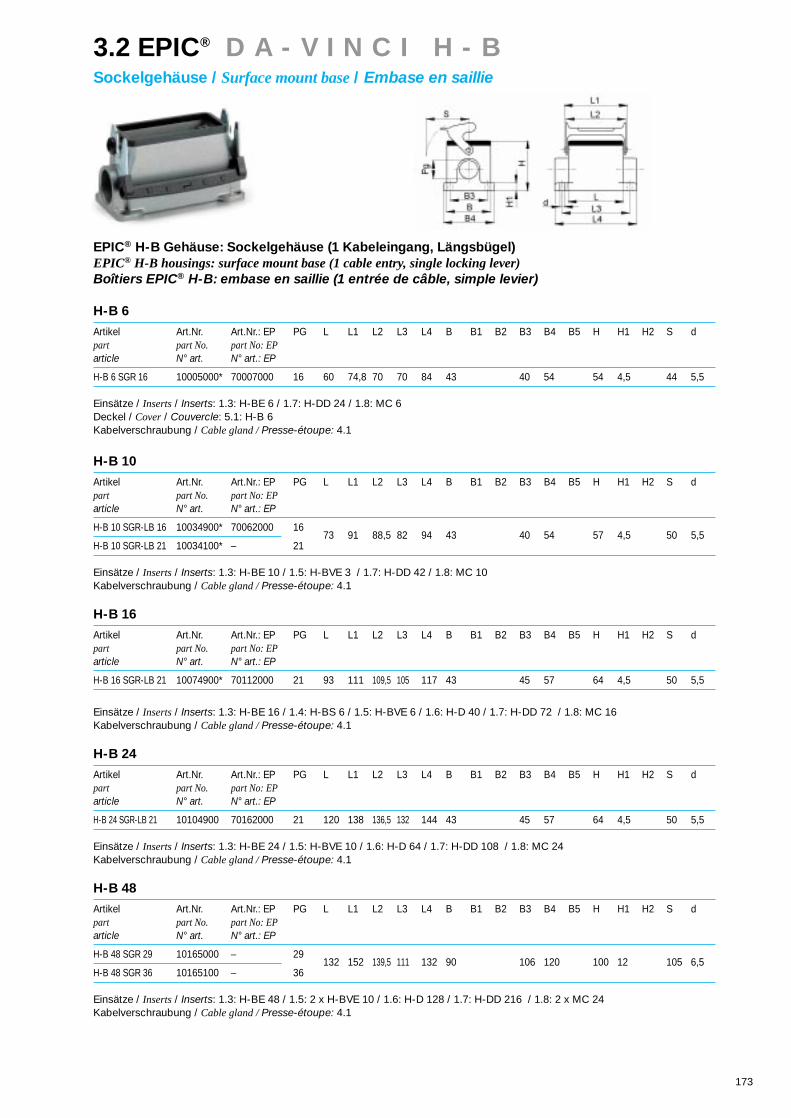
173
3.2 EPIC® D A - V I N C I H - BSockelgehäuse / Surface mount base/ Embase en saillie
EPIC® H-B Gehäuse: Sockelgehäuse (1 Kabeleingang, Längsbügel)EPIC® H-B housings: surface mount base (1 cable entry, single locking lever)Boîtiers EPIC® H-B: embase en saillie (1 entrée de câble, simple levier)
H-B 6
Artikel Art.Nr. Art.Nr.: EP PG L L1 L2 L3 L4 B B1 B2 B3 B4 B5 H H1 H2 S dpart part No. part No: EParticle N° art. N° art.: EP
H-B 6 SGR 16 10005000* 70007000 16 60 74,8 70 70 84 43 40 54 54 4,5 44 5,5
Einsätze / Inserts/ Inserts: 1.3: H-BE 6 / 1.7: H-DD 24 / 1.8: MC 6Deckel / Cover/ Couvercle: 5.1: H-B 6Kabelverschraubung / Cable gland / Presse-étoupe: 4.1
H-B 10
Artikel Art.Nr. Art.Nr.: EP PG L L1 L2 L3 L4 B B1 B2 B3 B4 B5 H H1 H2 S dpart part No. part No: EParticle N° art. N° art.: EP
H-B 10 SGR-LB 16 10034900* 70062000 16
H-B 10 SGR-LB 21 10034100* – 2173 91 88,5 82 94 43 40 54 57 4,5 50 5,5
Einsätze / Inserts/ Inserts: 1.3: H-BE 10 / 1.5: H-BVE 3 / 1.7: H-DD 42 / 1.8: MC 10Kabelverschraubung / Cable gland / Presse-étoupe: 4.1
H-B 16
Artikel Art.Nr. Art.Nr.: EP PG L L1 L2 L3 L4 B B1 B2 B3 B4 B5 H H1 H2 S dpart part No. part No: EParticle N° art. N° art.: EP
H-B 16 SGR-LB 21 10074900* 70112000 21 93 111 109,5 105 117 43 45 57 64 4,5 50 5,5
Einsätze / Inserts/ Inserts: 1.3: H-BE 16 / 1.4: H-BS 6 / 1.5: H-BVE 6 / 1.6: H-D 40 / 1.7: H-DD 72 / 1.8: MC 16Kabelverschraubung / Cable gland / Presse-étoupe: 4.1
H-B 24
Artikel Art.Nr. Art.Nr.: EP PG L L1 L2 L3 L4 B B1 B2 B3 B4 B5 H H1 H2 S dpart part No. part No: EParticle N° art. N° art.: EP
H-B 24 SGR-LB 21 10104900 70162000 21 120 138 136,5 132 144 43 45 57 64 4,5 50 5,5
Einsätze / Inserts/ Inserts: 1.3: H-BE 24 / 1.5: H-BVE 10 / 1.6: H-D 64 / 1.7: H-DD 108 / 1.8: MC 24Kabelverschraubung / Cable gland / Presse-étoupe: 4.1
H-B 48
Artikel Art.Nr. Art.Nr.: EP PG L L1 L2 L3 L4 B B1 B2 B3 B4 B5 H H1 H2 S dpart part No. part No: EParticle N° art. N° art.: EP
H-B 48 SGR 29 10165000 – 29
H-B 48 SGR 36 10165100 – 36132 152 139,5 111 132 90 106 120 100 12 105 6,5
Einsätze / Inserts/ Inserts: 1.3: H-BE 48 / 1.5: 2 x H-BVE 10 / 1.6: H-D 128 / 1.7: H-DD 216 / 1.8: 2 x MC 24Kabelverschraubung / Cable gland / Presse-étoupe: 4.1

174
EPIC® H-B Gehäuse: Sockelgehäuse (1 Kabeleingang, Längsbügel, hohe Bauform)EPIC® H-B housings: surface mount base (1 cable entry, single locking lever, high version)Boîtiers EPIC® H-B: embase en saillie (1 entrée de câble, simple levier, version haute)
H-B 6
Artikel Art.Nr. Art.Nr.: EP PG L L1 L2 L3 L4 B B1 B2 B3 B4 B5 H H1 H2 S dpart part No. part No: EParticle N° art. N° art.: EP
H-B 6 SGRH 21 70005200 70007200 21
H-B 6 SGRH 29 70005400 70007400 2960 74,8 70 70 84 43 45 58 74 6 44 5,5
Einsätze / Inserts/ Inserts: 1.3: H-BE 6 / 1.7: H-DD 24 / 1.8: MC 6Deckel / Cover/ Couvercle: 5.1: H-B 6Kabelverschraubung / Cable gland / Presse-étoupe: 4.1
H-B 10
Artikel Art.Nr. Art.Nr.: EP PG L L1 L2 L3 L4 B B1 B2 B3 B4 B5 H H1 H2 S dpart part No. part No: EParticle N° art. N° art.: EP
H-B 10 SGRH-LB 21 70060200 70062200 21
H-B 10 SGRH-LB 29 70060400 70062400 2973 91 88,5 82 97 43 45 58 74 6 50 5,5
Einsätze / Inserts/ Inserts: 1.3: H-BE 10 / 1.5: H-BVE 3 / 1.7: H-DD 42 / 1.8: MC 10Kabelverschraubung / Cable gland / Presse-étoupe: 4.1
H-B 16
Artikel Art.Nr. Art.Nr.: EP PG L L1 L2 L3 L4 B B1 B2 B3 B4 B5 H H1 H2 S dpart part No. part No: EParticle N° art. N° art.: EP
H-B 16 SGRH-LB 21 70110200 70112200 21
H-B 16 SGRH-LB 29 70110400 70112400 2993,3 111 109,5 105 117 43 45 58 84 6 50 5,5
Einsätze / Inserts/ Inserts: 1.3: H-BE 16 / 1.4: H-BS 6 / 1.5: H-BVE 6 / 1.6: H-D 40 / 1.7: H-DD 72 / 1.8: MC 16Kabelverschraubung / Cable gland / Presse-étoupe: 4.1
H-B 24
Artikel Art.Nr. Art.Nr.: EP PG L L1 L2 L3 L4 B B1 B2 B3 B4 B5 H H1 H2 S dpart part No. part No: EParticle N° art. N° art.: EP
H-B 24 SGRH-LB 21 70160200 70162200 21
H-B 24SGRH-LB 29 70160400 70162400 29120 138 136,5 132 144 43 45 58 84 6 50 5,5
Einsätze / Inserts/ Inserts: 1.3: H-BE 24 / 1.5: H-BVE 10 / 1.6: H-D 64 / 1.7: H-DD 108 / 1.8: MC 24Kabelverschraubung / Cable gland / Presse-étoupe: 4.1
3.2 EPIC® D A - V I N C I H - BSockelgehäuse / Surface mount base/ Embase en saillie

175
EPIC® H-B Gehäuse: Sockelgehäuse (Schutzdeckel, 2 Kabeleingänge, Längsbügel)EPIC® H-B housings: surface mount base (cover, 2 cable entries, single locking lever)Boîtiers EPIC® H-B: embase en saillie (couvercle, 2 entrées de câble, simple levier)
H-B 6
Artikel Art.Nr. Art.Nr.: EP PG L L1 L2 L3 L4 B B1 B2 B3 B4 B5 H H1 H2 S dpart part No. part No: EParticle N° art. N° art.: EP
H-B 6 SDRL 16 10009000* 70018000 16 60 74,8 70 70 84 43 40 54 25 54 4,5 44 5,5
Einsätze / Inserts/ Inserts: 1.3: H-BE 6 / 1.7: H-DD 24 / 1.8: MC 6Kabelverschraubung / Cable gland / Presse-étoupe: 4.1
H-B 10
Artikel Art.Nr. Art.Nr.: EP PG L L1 L2 L3 L4 B B1 B2 B3 B4 B5 H H1 H2 S dpart part No. part No: EParticle N° art. N° art.: EP
H-B 10 SDRL-LB 16 10038900* 70067000 16 73 91 88,5 82 94 43 40 54 25 57 4,5 50 5,5
Einsätze / Inserts/ Inserts: 1.3: H-BE 10 / 1.5: H-BVE 3 / 1.7: H-DD 42 / 1.8: MC 10Kabelverschraubung / Cable gland / Presse-étoupe: 4.1
H-B 16
Artikel Art.Nr. Art.Nr.: EP PG L L1 L2 L3 L4 B B1 B2 B3 B4 B5 H H1 H2 S dpart part No. part No: EParticle N° art. N° art.: EP
H-B 16 SDRL-LB 21 10078900* 70117000 21 93 111 109,5 105 117 43 45 57 25 64 4,5 50 5,5
Einsätze / Inserts/ Inserts: 1.3: H-BE 16 / 1.4: H-BS 6 / 1.5: H-BVE 6 / 1.6: H-D 40 / 1.7: H-DD 72 / 1.8: MC 16Kabelverschraubung / Cable gland / Presse-étoupe: 4.1
H-B 24
Artikel Art.Nr. Art.Nr.: EP PG L L1 L2 L3 L4 B B1 B2 B3 B4 B5 H H1 H2 S dpart part No. part No: EParticle N° art. N° art.: EP
H-B 24 SDRL-LB 21 10109900* 70167000 21 120 138 136,5 132 144 43 45 57 25 64 4,5 50 5,5
Einsätze / Inserts/ Inserts: 1.3: H-BE 24 / 1.5: H-BVE 10 / 1.6: H-D 64 / 1.7: H-DD 108 / 1.8: MC 24Kabelverschraubung / Cable gland / Presse-étoupe: 4.1
H-B 48
Artikel Art.Nr. Art.Nr.: EP PG L L1 L2 L3 L4 B B1 B2 B3 B4 B5 H H1 H2 S dpart part No. part No: EParticle N° art. N° art.: EP
H-B 48 SDRL 29 10168000 – 29
H-B 48 SDRL 36 10168100 – 36132 152 139,5 111 132 90 106 120 30 100 12 105 6,5
Einsätze / Inserts/ Inserts: 1.3: H-BE 48 / 1.5: 2 x H-BVE 10 / 1.6: H-D 128 / 1.7: H-DD 216 / 1.8: 2 x MC 24Kabelverschraubung / Cable gland / Presse-étoupe: 4.1
3.2 EPIC® D A - V I N C I H - BSockelgehäuse / Surface mount base/ Embase en saillie

EPIC® H-B Gehäuse: Sockelgehäuse (Schutzdeckel, 2 Kabeleingänge, Längsbügel, hohe Bauform)EPIC® H-B housings: surface mount base (cover, 2 cable entries, single locking lever, high version)Boîtiers EPIC® H-B: embase en saillie (couvercle, 2 entrées de câble, simple levier, version haute)
H-B 6
Artikel Art.Nr. Art.Nr.: EP PG L L1 L2 L3 L4 B B1 B2 B3 B4 B5 H H1 H2 S dpart part No. part No: EParticle N° art. N° art.: EP
H-B 6 SDRLH 21 70016200 70018200 21
H-B 6 SDRLH 29 70016400 70018400 2960 74,8 70 70 84 43 45 58 25 74 6 44 5,5
Einsätze / Inserts/ Inserts: 1.3: H-BE 6 / 1.7: H-DD 24 / 1.8: MC 6Kabelverschraubung / Cable gland / Presse-étoupe: 4.1
H-B 10
Artikel Art.Nr. Art.Nr.: EP PG L L1 L2 L3 L4 B B1 B2 B3 B4 B5 H H1 H2 S dpart part No. part No: EParticle N° art. N° art.: EP
H-B 10 SDRLH-LB 21 70065200 70067200 21
H-B 10 SDRLH-LB 29 70065400 70067400 2973 91 88,5 82 97 43 45 58 25 74 6 50 5,5
Einsätze / Inserts/ Inserts: 1.3: H-BE 10 / 1.5: H-BVE 3 / 1.7: H-DD 42 / 1.8: MC 10Kabelverschraubung / Cable gland / Presse-étoupe: 4.1
H-B 16
Artikel Art.Nr. Art.Nr.: EP PG L L1 L2 L3 L4 B B1 B2 B3 B4 B5 H H1 H2 S dpart part No. part No: EParticle N° art. N° art.: EP
H-B 16 SDRLH-LB 21 70115200 70117200 21
H-B 16 SDRLH-LB 29 70115400 70117400 2993,3 111 109,5 105 117 43 45 58 25 84 6 50 5,5
Einsätze / Inserts/ Inserts: 1.3: H-BE 16 / 1.4: H-BS 6 / 1.5: H-BVE 6 / 1.6: H-D 40 / 1.7: H-DD 72 / 1.8: MC 16Kabelverschraubung / Cable gland / Presse-étoupe: 4.1
H-B 24
Artikel Art.Nr. Art.Nr.: EP PG L L1 L2 L3 L4 B B1 B2 B3 B4 B5 H H1 H2 S dpart part No. part No: EParticle N° art. N° art.: EP
H-B 24 SDRLH-LB 21 70165200 70167200 21
H-B 24 SDRLH-LB 29 70165400 70167400 29120 138 136,5 132 144 43 45 58 25 84 6 50 5,5
Einsätze / Inserts/ Inserts: 1.3: H-BE 24 / 1.5: H-BVE 10 / 1.6: H-D 64 / 1.7: H-DD 108 / 1.8: MC 24Kabelverschraubung / Cable gland / Presse-étoupe: 4.1
176
3.2 EPIC® D A - V I N C I H - BSockelgehäuse / Surface mount base/ Embase en saillie
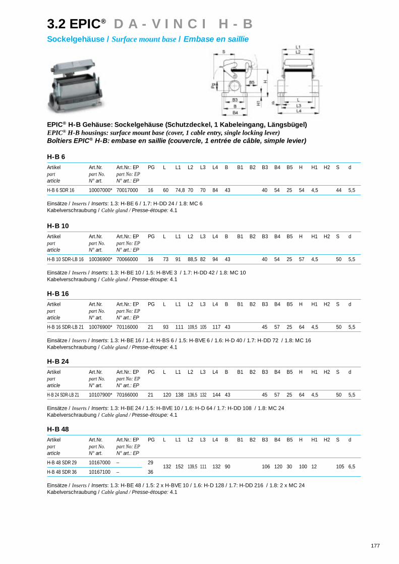
3.2 EPIC® D A - V I N C I H - BSockelgehäuse / Surface mount base/ Embase en saillie
177
EPIC® H-B Gehäuse: Sockelgehäuse (Schutzdeckel, 1 Kabeleingang, Längsbügel)EPIC® H-B housings: surface mount base (cover, 1 cable entry, single locking lever)Boîtiers EPIC® H-B: embase en saillie (couvercle, 1 entrée de câble, simple levier)
H-B 6
Artikel Art.Nr. Art.Nr.: EP PG L L1 L2 L3 L4 B B1 B2 B3 B4 B5 H H1 H2 S dpart part No. part No: EParticle N° art. N° art.: EP
H-B 6 SDR 16 10007000* 70017000 16 60 74,8 70 70 84 43 40 54 25 54 4,5 44 5,5
Einsätze / Inserts/ Inserts: 1.3: H-BE 6 / 1.7: H-DD 24 / 1.8: MC 6Kabelverschraubung / Cable gland / Presse-étoupe: 4.1
H-B 10
Artikel Art.Nr. Art.Nr.: EP PG L L1 L2 L3 L4 B B1 B2 B3 B4 B5 H H1 H2 S dpart part No. part No: EParticle N° art. N° art.: EP
H-B 10 SDR-LB 16 10036900* 70066000 16 73 91 88,5 82 94 43 40 54 25 57 4,5 50 5,5
Einsätze / Inserts/ Inserts: 1.3: H-BE 10 / 1.5: H-BVE 3 / 1.7: H-DD 42 / 1.8: MC 10Kabelverschraubung / Cable gland / Presse-étoupe: 4.1
H-B 16
Artikel Art.Nr. Art.Nr.: EP PG L L1 L2 L3 L4 B B1 B2 B3 B4 B5 H H1 H2 S dpart part No. part No: EParticle N° art. N° art.: EP
H-B 16 SDR-LB 21 10076900* 70116000 21 93 111 109,5 105 117 43 45 57 25 64 4,5 50 5,5
Einsätze / Inserts/ Inserts: 1.3: H-BE 16 / 1.4: H-BS 6 / 1.5: H-BVE 6 / 1.6: H-D 40 / 1.7: H-DD 72 / 1.8: MC 16Kabelverschraubung / Cable gland / Presse-étoupe: 4.1
H-B 24
Artikel Art.Nr. Art.Nr.: EP PG L L1 L2 L3 L4 B B1 B2 B3 B4 B5 H H1 H2 S dpart part No. part No: EParticle N° art. N° art.: EP
H-B 24 SDR-LB 21 10107900* 70166000 21 120 138 136,5 132 144 43 45 57 25 64 4,5 50 5,5
Einsätze / Inserts/ Inserts: 1.3: H-BE 24 / 1.5: H-BVE 10 / 1.6: H-D 64 / 1.7: H-DD 108 / 1.8: MC 24Kabelverschraubung / Cable gland / Presse-étoupe: 4.1
H-B 48
Artikel Art.Nr. Art.Nr.: EP PG L L1 L2 L3 L4 B B1 B2 B3 B4 B5 H H1 H2 S dpart part No. part No: EParticle N° art. N° art.: EP
H-B 48 SDR 29 10167000 – 29
H-B 48 SDR 36 10167100 – 36132 152 139,5 111 132 90 106 120 30 100 12 105 6,5
Einsätze / Inserts/ Inserts: 1.3: H-BE 48 / 1.5: 2 x H-BVE 10 / 1.6: H-D 128 / 1.7: H-DD 216 / 1.8: 2 x MC 24Kabelverschraubung / Cable gland / Presse-étoupe: 4.1

178
EPIC® H-B Gehäuse: Sockelgehäuse (Schutzdeckel, 1 Kabeleingang, Längsbügel, hohe Bauform)EPIC® H-B housings: surface mount base (cover, 1 cable entry, single locking lever, high version)Boîtiers EPIC® H-B: embase en saillie (couvercle, 1 entrée de câble, simple levier, version haute)
H-B 6
Artikel Art.Nr. Art.Nr.: EP PG L L1 L2 L3 L4 B B1 B2 B3 B4 B5 H H1 H2 S dpart part No. part No: EParticle N° art. N° art.: EP
H-B 6 SDRH 21 70015200 70017200 21
H-B 6 SDRH 29 70015400 70017400 2960 74,8 70 70 84 43 45 58 25 74 6 44 5,5
Einsätze / Inserts/ Inserts: 1.3: H-BE 6 / 1.7: H-DD 24 / 1.8: MC 6Kabelverschraubung / Cable gland / Presse-étoupe: 4.1
H-B 10
Artikel Art.Nr. Art.Nr.: EP PG L L1 L2 L3 L4 B B1 B2 B3 B4 B5 H H1 H2 S dpart part No. part No: EParticle N° art. N° art.: EP
H-B 10 SDRH-LB 21 70064200 70066200 21
H-B 10 SDRH-LB 29 70064400 70066400 2973 91 88,5 82 97 43 45 58 25 74 6 50 5,5
Einsätze / Inserts/ Inserts: 1.3: H-BE 10 / 1.5: H-BVE 3 / 1.7: H-DD 42 / 1.8: MC 10Kabelverschraubung / Cable gland / Presse-étoupe: 4.1
H-B 16
Artikel Art.Nr. Art.Nr.: EP PG L L1 L2 L3 L4 B B1 B2 B3 B4 B5 H H1 H2 S dpart part No. part No: EParticle N° art. N° art.: EP
H-B 16 SDRH-LB 21 70114200 70116200 21
H-B 16 SDRH-LB 29 70114400 70116400 2993,3 111 109,5 105 117 43 45 58 25 84 6 50 5,5
Einsätze / Inserts/ Inserts: 1.3: H-BE 16 / 1.4: H-BS 6 / 1.5: H-BVE 6 / 1.6: H-D 40 / 1.7: H-DD 72 / 1.8: MC 16Kabelverschraubung / Cable gland / Presse-étoupe: 4.1
H-B 24
Artikel Art.Nr. Art.Nr.: EP PG L L1 L2 L3 L4 B B1 B2 B3 B4 B5 H H1 H2 S dpart part No. part No: EParticle N° art. N° art.: EP
H-B 24 SDRH-LB 21 70164200 70166200 21
H-B 24 SDRH-LB 29 70164400 70166400 29120 138 136,5 132 144 43 45 58 25 84 6 50 5,5
Einsätze / Inserts/ Inserts: 1.3: H-BE 24 / 1.5: H-BVE 10 / 1.6: H-D 64 / 1.7: H-DD 108 / 1.8: MC 24Kabelverschraubung / Cable gland / Presse-étoupe: 4.1
3.2 EPIC® D A - V I N C I H - BSockelgehäuse / Surface mount base/ Embase en saillie

179
EPIC® H-B Gehäuse: Sockelgehäuse (2 Kabeleingänge, Querbügel)EPIC® H-B housings: surface mount base (2 cable entries, double locking lever)Boîtiers EPIC® H-B: embase en saillie (2 entrées de câble, double levier)
H-B 10
Artikel Art.Nr. Art.Nr.: EP PG L L1 L2 L3 L4 B B1 B2 B3 B4 B5 H H1 H2 S dpart part No. part No: EParticle N° art. N° art.: EP
H-B 10 SGRL 16 10035000* 70038000 16 73 27 82 94 43 57,8 53 40 54 57 4,5 116 5,5
Einsätze / Inserts/ Inserts: 1.3: H-BE 10 / 1.5: H-BVE 3 / 1.7: H-DD 42 / 1.8: MC 10Deckel / Cover/ Couvercle: 5.1: H-B 10Kabelverschraubung / Cable gland / Presse-étoupe: 4.1
H-B 16
Artikel Art.Nr. Art.Nr.: EP PG L L1 L2 L3 L4 B B1 B2 B3 B4 B5 H H1 H2 S dpart part No. part No: EParticle N° art. N° art.: EP
H-B 16 SGRL 21 10075000* 70088000 21 93 47,5 105 117 43 57,8 53 45 57 64 4,5 136,5 5,5
Einsätze / Inserts/ Inserts: 1.3: H-BE 16 / 1.4: H-BS 6 / 1.5: H-BVE 6 / 1.6: H-D 40 / 1.7: H-DD 72 / 1.8: MC 16Deckel / Cover/ Couvercle: 5.1: H-B 16Kabelverschraubung / Cable gland / Presse-étoupe: 4.1
H-B 24
Artikel Art.Nr. Art.Nr.: EP PG L L1 L2 L3 L4 B B1 B2 B3 B4 B5 H H1 H2 S dpart part No. part No: EParticle N° art. N° art.: EP
H-B 24 SGRL 21 10105000* 70138000 21 120 74 132 144 43 57,8 53 45 57 64 4,5 163 5,5
Einsätze / Inserts/ Inserts: 1.3: H-BE 24 / 1.5: H-BVE 10 / 1.6: H-D 64 / 1.7: H-DD 108 / 1.8: MC 24Kabelverschraubung / Cable gland / Presse-étoupe: 4.1
H-B 32
Artikel Art.Nr. Art.Nr.: EP PG L L1 L2 L3 L4 B B1 B2 B3 B4 B5 H H1 H2 S dpart part No. part No: EParticle N° art. N° art.: EP
H-B 32 SGRL 29 10138000 – 29 93,5 64,5 112 124,5 79 93,8 87,8 67 81 72 5 136,5 5,5
Einsätze / Inserts/ Inserts: 1.3: H-BE 32 / 1.4: H-BS 12 / 1.6: H-D 80 / 1.7: H-DD 144 / 1.8: 2 x MC 16Kabelverschraubung / Cable gland / Presse-étoupe: 4.1
3.2 EPIC® D A - V I N C I H - BSockelgehäuse / Surface mount base/ Embase en saillie

180
EPIC® H-B Gehäuse: Sockelgehäuse (2 Kabeleingänge, Querbügel, hohe Bauform)EPIC® H-B housings: surface mount base (2 cable entries, double locking lever, high version)Boîtiers EPIC® H-B: embase en saillie (2 entrées de câble, double levier, version haute)
H-B 10
Artikel Art.Nr. Art.Nr.: EP PG L L1 L2 L3 L4 B B1 B2 B3 B4 B5 H H1 H2 S dpart part No. part No: EParticle N° art. N° art.: EP
H-B 10 SGRLH 21 70036200 70038200 21
H-B 10 SGRLH 29 70036400 70038400 2973 27 82 97 43 57,8 53 45 58 74 6 116 5,5
Einsätze / Inserts/ Inserts: 1.3: H-BE 10 / 1.5: H-BVE 3 / 1.7: H-DD 42 / 1.8: MC 10Deckel / Cover/ Couvercle: 5.1: H-B 10Kabelverschraubung / Cable gland / Presse-étoupe: 4.1
H-B 16
Artikel Art.Nr. Art.Nr.: EP PG L L1 L2 L3 L4 B B1 B2 B3 B4 B5 H H1 H2 S dpart part No. part No: EParticle N° art. N° art.: EP
H-B 16 SGRLH 21 70086200 70088200 21
H-B 16 SGRLH 29 70086400 70088400 2993,3 47,5 105 117 43 57,8 53 45 58 84 6 136,5 5,5
Einsätze / Inserts/ Inserts: 1.3: H-BE 16 / 1.4: H-BS 6 / 1.5: H-BVE 6 / 1.6: H-D 40 / 1.7: H-DD 72 / 1.8: MC 16Deckel / Cover/ Couvercle: 5.1: H-B 16Kabelverschraubung / Cable gland / Presse-étoupe: 4.1
H-B 24
Artikel Art.Nr. Art.Nr.: EP PG L L1 L2 L3 L4 B B1 B2 B3 B4 B5 H H1 H2 S dpart part No. part No: EParticle N° art. N° art.: EP
H-B 24 SGRLH 21 70136200 70138200 21
H-B 24 SGRLH 29 70136400 70138400 29120 74 132 144 43 57,8 53 45 58 84 6 163 5,5
Einsätze / Inserts/ Inserts: 1.3: H-BE 24 / 1.5: H-BVE 10 / 1.6: H-D 64 / 1.7: H-DD 108 / 1.8: MC 24Deckel / Cover/ Couvercle: 5.1: H-B 24Kabelverschraubung / Cable gland / Presse-étoupe: 4.1
3.2 EPIC® D A - V I N C I H - BSockelgehäuse / Surface mount base/ Embase en saillie

181
EPIC® H-B Gehäuse: Sockelgehäuse (1 Kabeleingang, Querbügel)EPIC® H-B housings: surface mount base (1 cable entry, double locking lever)Boîtiers EPIC® H-B: embase en saillie (1 entrée de câble, double levier)
H-B 10
Artikel Art.Nr. Art.Nr.: EP PG L L1 L2 L3 L4 B B1 B2 B3 B4 B5 H H1 H2 S dpart part No. part No: EParticle N° art. N° art.: EP
H-B 10 SGR 16 10034000* 70037000 16 73 27 82 94 43 57,8 53 40 54 57 4,5 116 5,5
Einsätze / Inserts/ Inserts: 1.3: H-BE 10 / 1.5: H-BVE 3 / 1.7: H-DD 42 / 1.8: MC 10Deckel / Cover/ Couvercle: 5.1: H-B 10Kabelverschraubung / Cable gland / Presse-étoupe: 4.1
H-B 16
Artikel Art.Nr. Art.Nr.: EP PG L L1 L2 L3 L4 B B1 B2 B3 B4 B5 H H1 H2 S dpart part No. part No: EParticle N° art. N° art.: EP
H-B 16 SGR 21 10074000* 70087000 21 93 47,5 105 117 43 57,8 53 45 57 64 4,5 136,5 5,5
Einsätze / Inserts/ Inserts: 1.3: H-BE 16 / 1.4: H-BS 6 / 1.5: H-BVE 6 / 1.6: H-D 40 / 1.7: H-DD 72 / 1.8: MC 16Deckel / Cover/ Couvercle: 5.1: H-B 16Kabelverschraubung / Cable gland / Presse-étoupe: 4.1
H-B 24
Artikel Art.Nr. Art.Nr.: EP PG L L1 L2 L3 L4 B B1 B2 B3 B4 B5 H H1 H2 S dpart part No. part No: EParticle N° art. N° art.: EP
H-B 24 SGR 21 10104000* 70137000 21 120 74 132 144 43 57,8 53 45 57 64 4,5 163 5,5
Einsätze / Inserts/ Inserts: 1.3: H-BE 24 / 1.5: H-BVE 10 / 1.6: H-D 64 / 1.7: H-DD 108 / 1.8: MC 24Deckel / Cover/ Couvercle: 5.1: H-B 24Kabelverschraubung / Cable gland / Presse-étoupe: 4.1
H-B 32
Artikel Art.Nr. Art.Nr.: EP PG L L1 L2 L3 L4 B B1 B2 B3 B4 B5 H H1 H2 S dpart part No. part No: EParticle N° art. N° art.: EP
H-B 32 SGR 29 10137000* – 29 93,5 64,5 112 124,5 79 93,8 87,8 67 81 72 5 136,5 5,5
Einsätze / Inserts/ Inserts: 1.3: H-BE 32 / 1.4: H-BS 12 / 1.6: H-D 80 / 1.7: H-DD 144 / 1.8: 2 x MC 16Kabelverschraubung / Cable gland / Presse-étoupe: 4.1
3.2 EPIC® D A - V I N C I H - BSockelgehäuse / Surface mount base/ Embase en saillie

182
EPIC® H-B Gehäuse: Sockelgehäuse (1 Kabeleingang, Querbügel, hohe Bauform)EPIC® H-B housings: surface mount base (1 cable entry, double locking lever, high version)Boîtiers EPIC® H-B: embase en saillie (1 entrée de câble, double levier, version haute)
H-B 10
Artikel Art.Nr. Art.Nr.: EP PG L L1 L2 L3 L4 B B1 B2 B3 B4 B5 H H1 H2 S dpart part No. part No: EParticle N° art. N° art.: EP
H-B 10 SGRH 21 70035200 70037200 21
H-B 10 SGRH 29 70035400 70037400 2973 27 82 97 43 57,8 53 45 58 74 6 116 5,5
Einsätze / Inserts/ Inserts: 1.3: H-BE 10 / 1.5: H-BVE 3 / 1.7: H-DD 42 / 1.8: MC 10Deckel / Cover/ Couvercle: 5.1: H-B 10Kabelverschraubung / Cable gland / Presse-étoupe: 4.1
H-B 16
Artikel Art.Nr. Art.Nr.: EP PG L L1 L2 L3 L4 B B1 B2 B3 B4 B5 H H1 H2 S dpart part No. part No: EParticle N° art. N° art.: EP
H-B 16 SGRH 21 70085200 70087200 21
H-B 16 SGRH 29 70085400 70087400 2993,3 47,5 105 117 43 57,8 53 45 58 84 6 136,5 5,5
Einsätze / Inserts/ Inserts: 1.3: H-BE 16 / 1.4: H-BS 6 / 1.5: H-BVE 6 / 1.6: H-D 40 / 1.7: H-DD 72 / 1.8: MC 16Deckel / Cover/ Couvercle: 5.1: H-B 16Kabelverschraubung / Cable gland / Presse-étoupe: 4.1
H-B 24
Artikel Art.Nr. Art.Nr.: EP PG L L1 L2 L3 L4 B B1 B2 B3 B4 B5 H H1 H2 S dpart part No. part No: EParticle N° art. N° art.: EP
H-B 24 SGRH 21 70135200 70137200 21
H-B 24 SGRH 29 70135400* 70137400 29120 74 132 144 43 57,8 53 45 58 84 6 163 5,5
Einsätze / Inserts/ Inserts: 1.3: H-BE 24 / 1.5: H-BVE 10 / 1.6: H-D 64 / 1.7: H-DD 108 / 1.8: MC 24Deckel / Cover/ Couvercle: 5.1: H-B 24Kabelverschraubung / Cable gland / Presse-étoupe: 4.1
3.2 EPIC® D A - V I N C I H - BSockelgehäuse / Surface mount base/ Embase en saillie

183
EPIC® H-B Gehäuse: Sockelgehäuse (Schutzdeckel, 2 Kabeleingänge, Bolzen für Querbügel)EPIC® H-B housings: surface mount base (cover, 2 cable entries, bolts for double locking lever)Boîtiers EPIC® H-B: embase en saillie (couvercle, 2 entrées de câble, ergots pour double levier)
H-B 10
Artikel Art.Nr. Art.Nr.: EP PG L L1 L2 L3 L4 B B1 B2 B3 B4 B5 H H1 H2 S dpart part No. part No: EParticle N° art. N° art.: EP
H-B 10 SDRL-BO 16 10038000 70048000 16 73 27 82 94 43 57,8 40 54 25 57 4,5 5,5
Einsätze / Inserts/ Inserts: 1.3: H-BE 10 / 1.5: H-BVE 3 / 1.7: H-DD 42 / 1.8: MC 10Kabelverschraubung / Cable gland / Presse-étoupe: 4.1
H-B 16
Artikel Art.Nr. Art.Nr.: EP PG L L1 L2 L3 L4 B B1 B2 B3 B4 B5 H H1 H2 S dpart part No. part No: EParticle N° art. N° art.: EP
H-B 16 SDRL-BO 21 70096000 70098000 21 93 47,5 105 117 43 57,8 45 57 25 64 4,5 5,5
Einsätze / Inserts/ Inserts: 1.3: H-BE 16 / 1.4: H-BS 6 / 1.5: H-BVE 6 / 1.6: H-D 40 / 1.7: H-DD 72 / 1.8: MC 16Kabelverschraubung / Cable gland / Presse-étoupe: 4.1
H-B 24
Artikel Art.Nr. Art.Nr.: EP PG L L1 L2 L3 L4 B B1 B2 B3 B4 B5 H H1 H2 S dpart part No. part No: EParticle N° art. N° art.: EP
H-B 24 SDRL-BO 21 10109000 70148000 21 120 74 132 144 43 57,8 45 57 25 64 4,5 5,5
Einsätze / Inserts/ Inserts: 1.3: H-BE 24 / 1.5: H-BVE 10 / 1.6: H-D 64 / 1.7: H-DD 108 / 1.8: MC 24Kabelverschraubung / Cable gland / Presse-étoupe: 4.1
3.2 EPIC® D A - V I N C I H - BSockelgehäuse / Surface mount base/ Embase en saillie

184
EPIC® H-B Gehäuse: Sockelgehäuse (Schutzdeckel, 2 Kabeleingänge, Bolzen für Querbügel, hohe Bauform)EPIC® H-B housings: surface mount base (cover, 2 cable entries, bolts for double locking lever, high version)Boîtiers EPIC® H-B: embase en saillie (covercle, 2 entrées de câble, ergots pour double levier, version haute)
H-B 10
Artikel Art.Nr. Art.Nr.: EP PG L L1 L2 L3 L4 B B1 B2 B3 B4 B5 H H1 H2 S dpart part No. part No: EParticle N° art. N° art.: EP
H-B 10 SDRLH-BO 21 70046200 70048200 21
H-B 10 SDRLH-BO 29 70046400 70048400 2973 27 82 97 43 57,8 45 58 25 74 6 5,5
Einsätze / Inserts/ Inserts: 1.3: H-BE 10 / 1.5: H-BVE 3 / 1.7: H-DD 42 / 1.8: MC 10Kabelverschraubung / Cable gland / Presse-étoupe: 4.1
H-B 16
Artikel Art.Nr. Art.Nr.: EP PG L L1 L2 L3 L4 B B1 B2 B3 B4 B5 H H1 H2 S dpart part No. part No: EParticle N° art. N° art.: EP
H-B 16 SDRLH-BO 21 70096200 70098200 21
H-B 16 SDRLH-BO 29 70096400 70098400 2993,3 47,5 105 117 43 57,8 45 58 25 84 6 5,5
Einsätze / Inserts/ Inserts: 1.3: H-BE 16 / 1.4: H-BS 6 / 1.5: H-BVE 6 / 1.6: H-D 40 / 1.7: H-DD 72 / 1.8: MC 16Kabelverschraubung / Cable gland / Presse-étoupe: 4.1
H-B 24
Artikel Art.Nr. Art.Nr.: EP PG L L1 L2 L3 L4 B B1 B2 B3 B4 B5 H H1 H2 S dpart part No. part No: EParticle N° art. N° art.: EP
H-B 24 SDRLH-BO 21 70146200 70148200 21
H-B 24 SDRLH-BO 29 70146400 70148400 29120 74 132 144 43 57,8 45 58 25 84 6 5,5
Einsätze / Inserts/ Inserts: 1.3: H-BE 24 / 1.5: H-BVE 10 / 1.6: H-D 64 / 1.7: H-DD 108 / 1.8: MC 24Kabelverschraubung / Cable gland / Presse-étoupe: 4.1
3.2 EPIC® D A - V I N C I H - BSockelgehäuse / Surface mount base/ Embase en saillie

185
EPIC® H-B Gehäuse: Sockelgehäuse (Schutzdeckel, 1 Kabeleingang, Bolzen für Querbügel)EPIC® H-B housings: surface mount base (cover, 1 cable entry, bolts for double locking lever)Boîtiers EPIC® H-B: embase en saillie (couvercle, 1 entrée de câble, ergots pour double levier)
H-B 10
Artikel Art.Nr. Art.Nr.: EP PG L L1 L2 L3 L4 B B1 B2 B3 B4 B5 H H1 H2 S dpart part No. part No: EParticle N° art. N° art.: EP
H-B 10 SDR-BO 16 10036000 70047000 16 73 27 82 94 43 57,8 40 54 25 57 4,5 5,5
Einsätze / Inserts/ Inserts: 1.3: H-BE 10 / 1.5: H-BVE 3 / 1.7: H-DD 42 / 1.8: MC 10Kabelverschraubung / Cable gland / Presse-étoupe: 4.1
H-B 16
Artikel Art.Nr. Art.Nr.: EP PG L L1 L2 L3 L4 B B1 B2 B3 B4 B5 H H1 H2 S dpart part No. part No: EParticle N° art. N° art.: EP
H-B 16 SDR-BO 21 10076000 70097000 21 93 47,5 105 117 43 57,8 45 57 25 64 4,5 5,5
Einsätze / Inserts/ Inserts: 1.3: H-BE 16 / 1.4: H-BS 6 / 1.5: H-BVE 6 / 1.6: H-D 40 / 1.7: H-DD 72 / 1.8: MC 16Kabelverschraubung / Cable gland / Presse-étoupe: 4.1
H-B 24
Artikel Art.Nr. Art.Nr.: EP PG L L1 L2 L3 L4 B B1 B2 B3 B4 B5 H H1 H2 S dpart part No. part No: EParticle N° art. N° art.: EP
H-B 24 SDR-BO 21 10107000* 70147000 21 120 74 132 144 43 57,8 45 57 25 64 4,5 5,5
Einsätze / Inserts/ Inserts: 1.3: H-BE 24 / 1.5: H-BVE 10 / 1.6: H-D 64 / 1.7: H-DD 108 / 1.8: MC 24Kabelverschraubung / Cable gland / Presse-étoupe: 4.1
3.2 EPIC® D A - V I N C I H - BSockelgehäuse / Surface mount base/ Embase en saillie

186
EPIC® H-B Gehäuse: Sockelgehäuse (Schutzdeckel, 1 Kabeleingang, Bolzen für Querbügel, hohe Bauform)EPIC® H-B housings: surface mount base (cover, 1 cable entry, bolts for double locking lever, high version)Boîtiers EPIC® H-B: embase en saillie (covercle, 1 entrée de câble, ergots pour double levier, version haute)
H-B 10
Artikel Art.Nr. Art.Nr.: EP PG L L1 L2 L3 L4 B B1 B2 B3 B4 B5 H H1 H2 S dpart part No. part No: EParticle N° art. N° art.: EP
H-B 10 SDRH-BO 21 70045200 70047200 21
H-B 10 SDRH-BO 29 70045400 70047400 2973 27 82 97 43 57,8 45 58 25 74 6 5,5
Einsätze / Inserts/ Inserts: 1.3: H-BE 10 / 1.5: H-BVE 3 / 1.7: H-DD 42 / 1.8: MC 10Kabelverschraubung / Cable gland / Presse-étoupe: 4.1
H-B 16
Artikel Art.Nr. Art.Nr.: EP PG L L1 L2 L3 L4 B B1 B2 B3 B4 B5 H H1 H2 S dpart part No. part No: EParticle N° art. N° art.: EP
H-B 16 SDRH-BO 21 70095200 70097200 21
H-B 16 SDRH-BO 29 70095400 70097400 2993,3 47,5 105 117 43 57,8 45 58 25 84 6 5,5
Einsätze / Inserts/ Inserts: 1.3: H-BE 16 / 1.4: H-BS 6 / 1.5: H-BVE 6 / 1.6: H-D 40 / 1.7: H-DD 72 / 1.8: MC 16Kabelverschraubung / Cable gland / Presse-étoupe: 4.1
H-B 24
Artikel Art.Nr. Art.Nr.: EP PG L L1 L2 L3 L4 B B1 B2 B3 B4 B5 H H1 H2 S dpart part No. part No: EParticle N° art. N° art.: EP
H-B 24 SDRH-BO 21 70145200 70147200 21
H-B 24 SDRH-BO 29 70145400 70147400 29120 74 132 144 43 57,8 45 58 25 84 6 5,5
Einsätze / Inserts/ Inserts: 1.3: H-BE 24 / 1.5: H-BVE 10 / 1.6: H-D 64 / 1.7: H-DD 108 / 1.8: MC 24Kabelverschraubung / Cable gland / Presse-étoupe: 4.1
3.2 EPIC® D A - V I N C I H - BSockelgehäuse / Surface mount base/ Embase en saillie
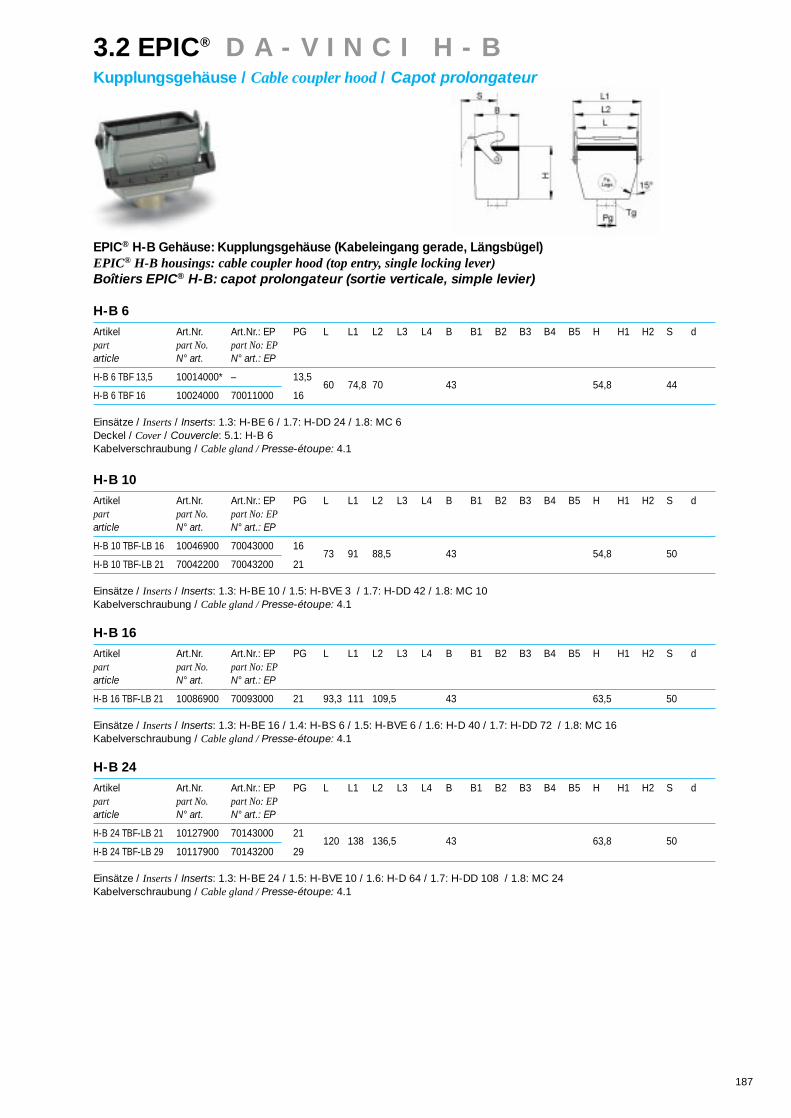
187
EPIC® H-B Gehäuse: Kupplungsgehäuse (Kabeleingang gerade, Längsbügel)EPIC® H-B housings: cable coupler hood (top entry, single locking lever)Boîtiers EPIC® H-B: capot prolongateur (sortie verticale, simple levier)
H-B 6
Artikel Art.Nr. Art.Nr.: EP PG L L1 L2 L3 L4 B B1 B2 B3 B4 B5 H H1 H2 S dpart part No. part No: EParticle N° art. N° art.: EP
H-B 6 TBF 13,5 10014000* – 13,5
H-B 6 TBF 16 10024000 70011000 1660 74,8 70 43 54,8 44
Einsätze / Inserts/ Inserts: 1.3: H-BE 6 / 1.7: H-DD 24 / 1.8: MC 6Deckel / Cover/ Couvercle: 5.1: H-B 6Kabelverschraubung / Cable gland / Presse-étoupe: 4.1
H-B 10
Artikel Art.Nr. Art.Nr.: EP PG L L1 L2 L3 L4 B B1 B2 B3 B4 B5 H H1 H2 S dpart part No. part No: EParticle N° art. N° art.: EP
H-B 10 TBF-LB 16 10046900 70043000 16
H-B 10 TBF-LB 21 70042200 70043200 2173 91 88,5 43 54,8 50
Einsätze / Inserts/ Inserts: 1.3: H-BE 10 / 1.5: H-BVE 3 / 1.7: H-DD 42 / 1.8: MC 10Kabelverschraubung / Cable gland / Presse-étoupe: 4.1
H-B 16
Artikel Art.Nr. Art.Nr.: EP PG L L1 L2 L3 L4 B B1 B2 B3 B4 B5 H H1 H2 S dpart part No. part No: EParticle N° art. N° art.: EP
H-B 16 TBF-LB 21 10086900 70093000 21 93,3 111 109,5 43 63,5 50
Einsätze / Inserts/ Inserts: 1.3: H-BE 16 / 1.4: H-BS 6 / 1.5: H-BVE 6 / 1.6: H-D 40 / 1.7: H-DD 72 / 1.8: MC 16Kabelverschraubung / Cable gland / Presse-étoupe: 4.1
H-B 24
Artikel Art.Nr. Art.Nr.: EP PG L L1 L2 L3 L4 B B1 B2 B3 B4 B5 H H1 H2 S dpart part No. part No: EParticle N° art. N° art.: EP
H-B 24 TBF-LB 21 10127900 70143000 21
H-B 24 TBF-LB 29 10117900 70143200 29120 138 136,5 43 63,8 50
Einsätze / Inserts/ Inserts: 1.3: H-BE 24 / 1.5: H-BVE 10 / 1.6: H-D 64 / 1.7: H-DD 108 / 1.8: MC 24Kabelverschraubung / Cable gland / Presse-étoupe: 4.1
3.2 EPIC® D A - V I N C I H - BKupplungsgehäuse / Cable coupler hood/ Capot prolongateur

188
3.2 EPIC® D A - V I N C I H - BKupplungsgehäuse / Cable coupler hood/ Capot prolongateur
EPIC® H-B Gehäuse: Kupplungsgehäuse (Kabeleingang gerade, Längsbügel, hohe Bauform)EPIC® H-B housings: cable coupler hood (top entry, single locking lever, high version)Boîtiers EPIC® H-B: capot prolongateur (sortie verticale, simple levier, version haute)
H-B 6
Artikel Art.Nr. Art.Nr.: EP PG L L1 L2 L3 L4 B B1 B2 B3 B4 B5 H H1 H2 S dpart part No. part No: EParticle N° art. N° art.: EP
H-B 6 TBFH 21 70010200 70011200 21
H-B 6 TBFH 29 70010400 70011400 2960 74,8 70 43 74,8 44
Einsätze / Inserts/ Inserts: 1.3: H-BE 6 / 1.7: H-DD 24 / 1.8: MC 6 / 1.9: TB-H-BE 6, TB-H-D 16Deckel / Cover/ Couvercle: 5.1: H-B 6Kabelverschraubung / Cable gland / Presse-étoupe: 4.1
H-B 10
Artikel Art.Nr. Art.Nr.: EP PG L L1 L2 L3 L4 B B1 B2 B3 B4 B5 H H1 H2 S dpart part No. part No: EParticle N° art. N° art.: EP
H-B 10 TBFH-LB 21 70042400 70043400 16
H-B 10 TBFH-LB 29 70042600 70043600 2173 91 88,5 43 74,8 50
Einsätze / Inserts/ Inserts: 1.3: H-BE 10 / 1.5: H-BVE 3 / 1.7: H-DD 42 / 1.8: MC 10Kabelverschraubung / Cable gland / Presse-étoupe: 4.1
H-B 16
Artikel Art.Nr. Art.Nr.: EP PG L L1 L2 L3 L4 B B1 B2 B3 B4 B5 H H1 H2 S dpart part No. part No: EParticle N° art. N° art.: EP
H-B 16 TBFH-LB 21 70092200 70093200 16
H-B 16 TBFH-LB 29 70092400 70093400 2193,3 111 109,5 43 78,8 50
Einsätze / Inserts/ Inserts: 1.3: H-BE 16 / 1.4: H-BS 6 / 1.5: H-BVE 6 / 1.6: H-D 40 / 1.7: H-DD 72 / 1.8: MC 16Kabelverschraubung / Cable gland / Presse-étoupe: 4.1
H-B 24
Artikel Art.Nr. Art.Nr.: EP PG L L1 L2 L3 L4 B B1 B2 B3 B4 B5 H H1 H2 S dpart part No. part No: EParticle N° art. N° art.: EP
H-B 24 TBFH-LB 21 70142400 70143400 21
H-B 24 TBFH-LB 29 70142600 70143600 29120 138 136,5 43 78,8 50
Einsätze / Inserts/ Inserts: 1.3: H-BE 24 / 1.5: H-BVE 10 / 1.6: H-D 64 / 1.7: H-DD 108 / 1.8: MC 24Kabelverschraubung / Cable gland / Presse-étoupe: 4.1

189
3.2 EPIC® D A - V I N C I H - BKupplungsgehäuse / Cable coupler hood/ Capot prolongateur
EPIC® H-B Gehäuse: Kupplungsgehäuse (Kabeleingang gerade, Querbügel)EPIC® H-B housings: cable coupler hood (top entry, double locking lever)Boîtiers EPIC® H-B: capot prolongateur (sortie verticale, double levier)
H-B 10
Artikel Art.Nr. Art.Nr.: EP PG L L1 L2 L3 L4 B B1 B2 B3 B4 B5 H H1 H2 S dpart part No. part No: EParticle N° art. N° art.: EP
H-B 10 TBF 16 10046000* 70041000 16
H-B 10 TBF 21 70040200 70041200 2173 27 43 57,8 53 54,8 116
Einsätze / Inserts/ Inserts: 1.3: H-BE 10 / 1.5: H-BVE 3 / 1.7: H-DD 42 / 1.8: MC 10Deckel / Cover/ Couvercle: 5.1: H-B 10Kabelverschraubung / Cable gland / Presse-étoupe: 4.1
H-B 16
Artikel Art.Nr. Art.Nr.: EP PG L L1 L2 L3 L4 B B1 B2 B3 B4 B5 H H1 H2 S dpart part No. part No: EParticle N° art. N° art.: EP
H-B 16 TBF 21 10086000* 70091000 21 93,3 47,5 43 57,8 53 63,6 136,5
Einsätze / Inserts/ Inserts: 1.3: H-BE 16 / 1.4: H-BS 6 / 1.5: H-BVE 6 / 1.6: H-D 40 / 1.7: H-DD 72 / 1.8: MC 16Deckel / Cover/ Couvercle: 5.1: H-B 16Kabelverschraubung / Cable gland / Presse-étoupe: 4.1
H-B 24
Artikel Art.Nr. Art.Nr.: EP PG L L1 L2 L3 L4 B B1 B2 B3 B4 B5 H H1 H2 S dpart part No. part No: EParticle N° art. N° art.: EP
H-B 24 TBF 21 10127000 70141000 21
H-B 24 TBF 29 10117000 70141200 29120 74 43 57,8 53 63,8 163
Einsätze / Inserts/ Inserts: 1.3: H-BE 24 / 1.5: H-BVE 10 / 1.6: H-D 64 / 1.7: H-DD 108 / 1.8: MC 24Deckel / Cover/ Couvercle: 5.1: H-B 24Kabelverschraubung / Cable gland / Presse-étoupe: 4.1
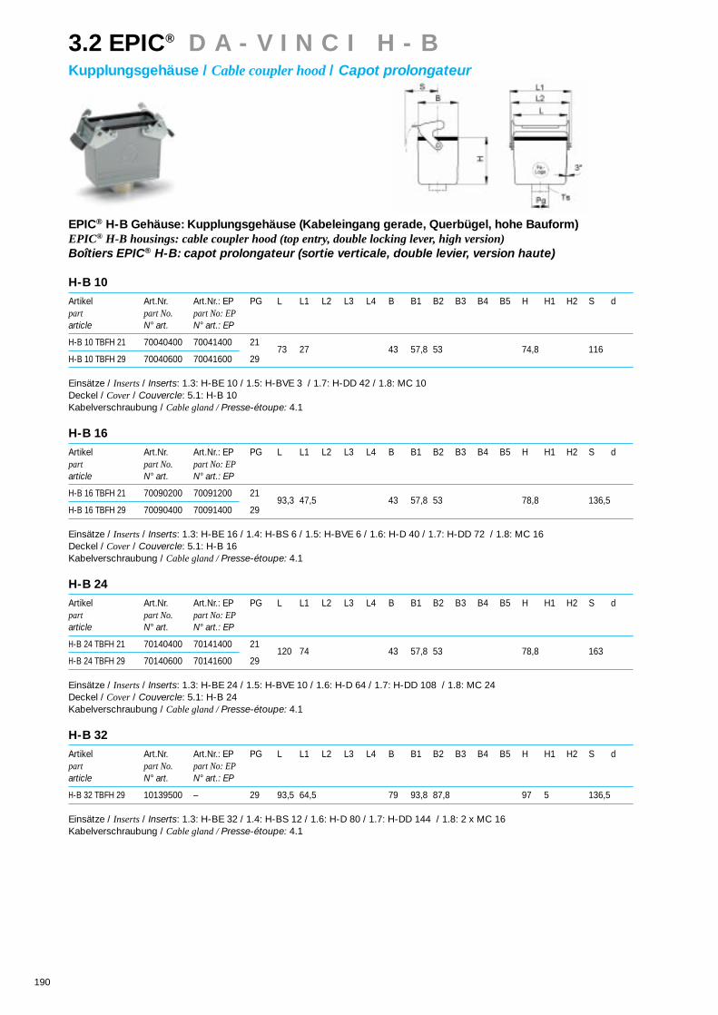
190
EPIC® H-B Gehäuse: Kupplungsgehäuse (Kabeleingang gerade, Querbügel, hohe Bauform)EPIC® H-B housings: cable coupler hood (top entry, double locking lever, high version)Boîtiers EPIC® H-B: capot prolongateur (sortie verticale, double levier, version haute)
H-B 10
Artikel Art.Nr. Art.Nr.: EP PG L L1 L2 L3 L4 B B1 B2 B3 B4 B5 H H1 H2 S dpart part No. part No: EParticle N° art. N° art.: EP
H-B 10 TBFH 21 70040400 70041400 21
H-B 10 TBFH 29 70040600 70041600 2973 27 43 57,8 53 74,8 116
Einsätze / Inserts/ Inserts: 1.3: H-BE 10 / 1.5: H-BVE 3 / 1.7: H-DD 42 / 1.8: MC 10Deckel / Cover/ Couvercle: 5.1: H-B 10Kabelverschraubung / Cable gland / Presse-étoupe: 4.1
H-B 16
Artikel Art.Nr. Art.Nr.: EP PG L L1 L2 L3 L4 B B1 B2 B3 B4 B5 H H1 H2 S dpart part No. part No: EParticle N° art. N° art.: EP
H-B 16 TBFH 21 70090200 70091200 21
H-B 16 TBFH 29 70090400 70091400 2993,3 47,5 43 57,8 53 78,8 136,5
Einsätze / Inserts/ Inserts: 1.3: H-BE 16 / 1.4: H-BS 6 / 1.5: H-BVE 6 / 1.6: H-D 40 / 1.7: H-DD 72 / 1.8: MC 16Deckel / Cover/ Couvercle: 5.1: H-B 16Kabelverschraubung / Cable gland / Presse-étoupe: 4.1
H-B 24
Artikel Art.Nr. Art.Nr.: EP PG L L1 L2 L3 L4 B B1 B2 B3 B4 B5 H H1 H2 S dpart part No. part No: EParticle N° art. N° art.: EP
H-B 24 TBFH 21 70140400 70141400 21
H-B 24 TBFH 29 70140600 70141600 29120 74 43 57,8 53 78,8 163
Einsätze / Inserts/ Inserts: 1.3: H-BE 24 / 1.5: H-BVE 10 / 1.6: H-D 64 / 1.7: H-DD 108 / 1.8: MC 24Deckel / Cover/ Couvercle: 5.1: H-B 24Kabelverschraubung / Cable gland / Presse-étoupe: 4.1
H-B 32
Artikel Art.Nr. Art.Nr.: EP PG L L1 L2 L3 L4 B B1 B2 B3 B4 B5 H H1 H2 S dpart part No. part No: EParticle N° art. N° art.: EP
H-B 32 TBFH 29 10139500 – 29 93,5 64,5 79 93,8 87,8 97 5 136,5
Einsätze / Inserts/ Inserts: 1.3: H-BE 32 / 1.4: H-BS 12 / 1.6: H-D 80 / 1.7: H-DD 144 / 1.8: 2 x MC 16Kabelverschraubung / Cable gland / Presse-étoupe: 4.1
3.2 EPIC® D A - V I N C I H - BKupplungsgehäuse / Cable coupler hood/ Capot prolongateur

191
Die Antwort auf geänderte Rahmen-
bedingungen. Der neue Standard,
umweltschonend und kostengünstig.
Die hochwertige Alulegierung und neue
Gußwerkzeuge erlauben uns, auf die
Beschichtung zu verzichten. Sie pro-
fitieren durch den einzigartigen EMV-
Schutz. Lieferbar im Set: Anbau- und
Tüllengehäuse der Baureihen H-B 16
und H-B 24.
Our answer to changing requirements.
The new standard, environmentally
friendly and cost-effective. The high-
grade aluminium alloys and new casting
tools enable us to dispense with the
coating. You benefit from the unique
EMC protection. Can be delivered as a
set: hood and panel mount base from
the H-B 16 and H-B 24 series.
Notre réponse aux conditions sans cesse
changeantes. Le nouveau standard, res-
pectueux de l’environnement et à prix
intéressant. L’alliage alu de haute qualité
et les nouveaux outils de moulage/
démoulage nous ont permis de supprimer
le revêtement. À vous de bénéficier de la
protection CEM unique de ce système.
Livrable en kit complet: embase et boîtier
à capot des séries H-B 16 et H-B 24.
3.3 EPIC® E c o H - BEco Set / Eco Set / Eco Set

192
3.3 EPIC® E c o H - BEco Set / Eco Set / Eco Set
Technische DatenVorschriften und Zulassungen: . . .Bauartnorm DIN 43652• Temperaturbereich: . . . . . . . . . .-40°C - +125°C• Schutzart: . . . . . . . . . . . . . . . . . .IP 65 nach DIN VDE 0470• Werkstoff: . . . . . . . . . . . . . . . . . .Aluminium-Legierung
Technical DataSpecification: . . . . . . . . . . . . . . . . . . . .DIN 43652 • Temperature range: . . . . . . . . . . . . .-40°C - +125°C • Protection class: . . . . . . . . . . . . . . .IP 65 according to DIN VDE 0470 • Material: . . . . . . . . . . . . . . . . . . . . .aluminium alloy
Caractéristiques techniquesRéglements et homologations: . . .DIN 43652• Plage de température: . . . . . . . .-40°C - +125°C • Protection: . . . . . . . . . . . . . . . . .IP 65 suivant DIN VDE 0470• Matériau: . . . . . . . . . . . . . . . . . .alliage AL
Frequenzfrequencyfréquence
Sch
irmd
ämp
fung
Shi
eld
ab
sorp
tion
alté
nuat
ion
des
inte
rfér
ence
sel
ectr
oméc
aniq
ues

193
3.3 EPIC® E c o H - BEco Set / Eco Set / Eco Set
H-B 6 - H-B 24 panel mount base/hood as seperat
components in version Epic® Eco.
Dans la version EPIC® Eco sont maintenant
disponibles les embases et les capots séparement.
H-B 6 - H-B 24
Anbau-/Tüllengehäuse als Einzelkomponenten
in EPIC® Eco Version
EPIC® Eco Set: Tülle/Anbaugehäuse (Kabeleingang gerade, Querbügel, Kabelverschraubung)EPIC® Eco Set: hood/panel mount base (top entry, double locking lever,cable gland)EPIC® Eco Set: capot/embase encastrée (sortie verticale, double levier, presse-étoupe)
H-B 16
Artikel Art.Nr. PG L L1 L2 L3 L4 B B1 B2 B3 B4 B5 H H1 H2 S dpart part No.article N° art.
H-B 16 TG / H-B 16 AG 70364000* 21
H-B 16 TG / H-B 16 AG 70364200* 2993,3 47,5 103 113 43 57,8 53 32 88,8 4 136,5 4,3
Einsätze / Inserts/ Inserts: 1.3: H-BE 16 / 1.4: H-BS 6 / 1.5: H-BVE 6 / 1.6: H-D 40 / 1.7: H-DD 72 / 1.8: MC 16 / 1.9: TB-H-BE 16,TB-H-D 40Deckel / Cover/ Couvercle: 5.1: H-B 16
H-B 24
Artikel Art.Nr. PG L L1 L2 L3 L4 B B1 B2 B3 B4 B5 H H1 H2 S dpart part No.article N° art.
H-B 24 TG / H-B 24 AG 70366000* 21
H-B 24 TG / H-B 24 AG 70366200* 29120 74 130 140 43 57,8 53 32 88,8 4 163 4,3
Einsätze / Inserts/ Inserts: 1.3: H-BE 24 / 1.5: H-BVE 10 / 1.6: H-D 64 / 1.7: H-DD 108 / 1.8: MC 24 / 1.9: TB-H-BE 24, TB-H-D 64Deckel / Cover/ Couvercle: 5.1: H-B 24
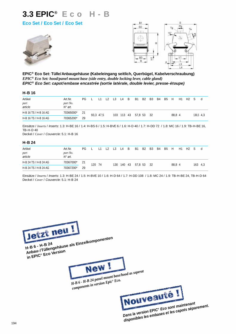
194
H-B 6 - H-B 24 panel mount base/hood as seperat
components in version Epic® Eco.
Dans la version EPIC® Eco sont maintenant
disponibles les embases et les capots séparement.
H-B 6 - H-B 24
Anbau-/Tüllengehäuse als Einzelkomponenten
in EPIC® Eco Version
3.3 EPIC® E c o H - BEco Set / Eco Set / Eco Set
EPIC® Eco Set: Tülle/Anbaugehäuse (Kabeleingang seitlich, Querbügel, Kabelverschraubung)EPIC® Eco Set: hood/panel mount base (side entry, double locking lever, cable gland)EPIC® Eco Set: capot/embase encastrée (sortie latérale, double levier, presse-étoupe)
H-B 16
Artikel Art.Nr. PG L L1 L2 L3 L4 B B1 B2 B3 B4 B5 H H1 H2 S dpart part No.article N° art.
H-B 16 TS / H-B 16 AG 70365000* 21
H-B 16 TS / H-B 16 AG 70365200* 2993,3 47,5 103 113 43 57,8 53 32 88,8 4 136,5 4,3
Einsätze / Inserts/ Inserts: 1.3: H-BE 16 / 1.4: H-BS 6 / 1.5: H-BVE 6 / 1.6: H-D 40 / 1.7: H-DD 72 / 1.8: MC 16 / 1.9: TB-H-BE 16,TB-H-D 40Deckel / Cover/ Couvercle: 5.1: H-B 16
H-B 24
Artikel Art.Nr. PG L L1 L2 L3 L4 B B1 B2 B3 B4 B5 H H1 H2 S dpart part No.article N° art.
H-B 24 TS / H-B 24 AG 70367000* 21
H-B 24 TS / H-B 24 AG 70367200* 29120 74 130 140 43 57,8 53 32 88,8 4 163 4,3
Einsätze / Inserts/ Inserts: 1.3: H-BE 24 / 1.5: H-BVE 10 / 1.6: H-D 64 / 1.7: H-DD 108 / 1.8: MC 24 / 1.9: TB-H-BE 24, TB-H-D 64Deckel / Cover/ Couvercle: 5.1: H-B 24

195
H-B 6 - H-B 24 panel mount base/hood as seperat
components in version Epic® Eco.
Dans la version EPIC® Eco sont maintenant
disponibles les embases et les capots séparement.
H-B 6 - H-B 24
Anbau-/Tüllengehäuse als Einzelkomponenten
in EPIC® Eco Version
3.3 EPIC® E c o H - BEco Set / Eco Set / Eco Set
EPIC® Eco Set: Tülle/Anbaugehäuse (Kabeleingang gerade, Längsbügel, Kabelverschraubung)EPIC® Eco Set: hood/panel mount base (top entry, single locking lever, cable gland)EPIC® Eco Set: capot/embase encastrée (sortie verticale, simple levier, presse-étoupe)
H-B 16
Artikel Art.Nr. PG L L1 L2 L3 L4 B B1 B2 B3 B4 B5 H H1 H2 S dpart part No.article N° art.
H-B 16 TG / H-B 16 AG-LB 70364100* 21
H-B 16 TG / H-B 16 AG-LB 70364300* 2993,3 111 109,5 103 113 43 32 88,8 4 50 4,3
Einsätze / Inserts/ Inserts: 1.3: H-BE 16 / 1.4: H-BS 6 / 1.5: H-BVE 6 / 1.6: H-D 40 / 1.7: H-DD 72 / 1.8: MC 16 / 1.9: TB-H-BE 16,TB-H-D 40
H-B 24
Artikel Art.Nr. PG L L1 L2 L3 L4 B B1 B2 B3 B4 B5 H H1 H2 S dpart part No.article N° art.
H-B 24 TG / H-B 24 AG-LB 70366100* 21
H-B 24 TG / H-B 24 AG-LB 70366300* 29120 138 136,5 130 140 43 32 88,8 4 50 4,3
Einsätze / Inserts/ Inserts: 1.3: H-BE 24 / 1.5: H-BVE 10 / 1.6: H-D 64 / 1.7: H-DD 108 / 1.8: MC 24 / 1.9: TB-H-BE 24, TB-H-D 64

196
H-B 6 - H-B 24 panel mount base/hood as seperat
components in version Epic® Eco.
Dans la version EPIC® Eco sont maintenant
disponibles les embases et les capots séparement.
H-B 6 - H-B 24
Anbau-/Tüllengehäuse als Einzelkomponenten
in EPIC® Eco Version
3.3 EPIC® E c o H - BEco Set / Eco Set / Eco Set
EPIC® Eco Set: Tülle/Anbaugehäuse (Kabeleingang seitlich, Längsbügel, Kabelverschraubung)EPIC® Eco Set: hood/panel mount base (top entry, single locking lever, cable gland)EPIC® Eco Set: capot/embase encastrée (sortie latérale, simple levier, presse-étoupe)
H-B 16
Artikel Art.Nr. PG L L1 L2 L3 L4 B B1 B2 B3 B4 B5 H H1 H2 S dpart part No.article N° art.
H-B 16 TS / H-B 16 AG-LB 70365100* 21
H-B 16 TS / H-B 16 AG-LB 70365300* 2993,3 111 109,5 103 113 43 32 88,8 4 50 4,3
Einsätze / Inserts/ Inserts: 1.3: H-BE 16 / 1.4: H-BS 6 / 1.5: H-BVE 6 / 1.6: H-D 40 / 1.7: H-DD 72 / 1.8: MC 16 / 1.9: TB-H-BE 16,TB-H-D 40
H-B 24
Artikel Art.Nr. PG L L1 L2 L3 L4 B B1 B2 B3 B4 B5 H H1 H2 S dpart part No.article N° art.
H-B 24 TS / H-B 24 AG-LB 70367100* 21
H-B 24 TS / H-B 24 AG-LB 70367300* 29120 138 136,5 130 140 43 32 88,8 4 50 4,3
Einsätze / Inserts/ Inserts: 1.3: H-BE 24 / 1.5: H-BVE 10 / 1.6: H-D 64 / 1.7: H-DD 108 / 1.8: MC 24 / 1.9: TB-H-BE 24, TB-H-D 64

197
Als notwendige Ergänzung für Steck-verbinder bietet CONTACT einfach zumontierende Kabelverschraubungenan, die den Anforderungen an Funkti-onssicherheit, EMV-Schutz und Kälte-beständigkeit gerecht werden.
Cable Glands are an important supple-ment to CONTACT’s range of connec-tors. Our glands ensure that the IP rat-ing of the connectors is not prejudiced,whilst offering an extensive variety offunctions including EMC protection.
Comme complément ingénieux auconnecteur nous vous proposons despresse-étoupes, avec un système EMV(Compatibilité Electro Magnétique oucontinuité de masse).
4.1 EPIC® C E R T O S AKabelverschraubungen / Cable glands/ Presse-étoupes

198
Kabelverschraubungen / Cable glands / Presse-étoupes
EPIC® SP (Kunststoff, Einschnittdichtring / plastic, split seal /plasique, joint multiple)
EPIC® SM (Metall, Einschnittdichtring / metal, split seal /métallique, joint multiple)
SKINTOP® ST (Kunststoff / plastic /plasique)
SKINTOP® BS (Kunststoff, Biegeschutzspirale / plastic, spiral bend prevention /plasique, spirale anti-torsion)
SKINTOP® MS (Metall / metal /métallique)
SKINTOP® MS-SC (Metall, EMV-Schutz / metal, EMC protection /métallique, Protection CEM)
SKINDICHT® SK (Metall, Zugentlastung / metal, traction relief / metallique, amarrage de câble
SKINDICHT® SH (Metall, Zugentlastung, Biegeschutz / metal, traction relief, bend prevention /metallique, amarrage de câble, anti-torsion)
SKINDICHT® SR (Metall, Zugentlastung, korrosionsbeständig, / metal, traction relief, corrosion resistant / metallique, amarrage de câble,
résistant à la corrosion)
SKINDICHT® ME (Metall, Erweiterung / metal, enlarging /métallique, amplificateur)
SKINDICHT® MR (Metall, Reduzierung / metal, reducing /métallique, reducteur)
SKINDICHT® BL(Metall, Verschlußschraube / metal, plug /métallique, bouchons de fermeture)
SKINDICHT® BLK (Kunststoff, Verschlußschraube / plastic, plug /plastique, bouchons de fermeture)
4.1 EPIC® C E R T O S AKabelverschraubungen / Cable glands/ Presse-étoupes
Metr.Gewinde NenngewindeMetric thread Nominal threadPas Métrique Dimension du filetage
DIN 46319 Ø d1 Ø d2 p Ø d3
M 12 x 1,5 10,38 12 1,5 12,5 ± 0,2
M 16 x 1,5 14,38 16 1,5 16,5 ± 0,2
M 20 x 1,5 18,38 20 1,5 20,5 ± 0,2
M 25 x 1,5 23,38 25 1,5 25,5 ± 0,2
M 32 x 1,5 30,38 32 1,5 32,5 ± 0,2
M 40 x 1,5 38,38 40 1,5 40,5 ± 0,3
M 50 x 1,5 48,38 50 1,5 50,5 ± 0,3
M 63 x 1,5 61,38 63 1,5 64,0 ± 0,3
PG-Gewinde NenngewindePg-Thread Nominal threadPas PG Dimension du filetage
DIN 89280 Ø d1 Ø d2 p Ø d3
M 18 x 1,5 16,38 18 1,5 18,5 ± 0,2
M 24 x 1,5 22,38 24 1,5 24,5 ± 0,2
M 30 x 2,0 27,34 30 2,0 30,5 ± 0,2
M 36 x 2,0 33,34 36 2,0 36,5 ± 0,2
M 45 x 2,0 42,34 45 2,0 45,5 ± 0,3
M 56 x 2,0 53,34 58 2,0 57,0 ± 0,3
M 72 x 2,0 68,82 72 2,0 73,0 ± 0,3
Gewindemaße / Thread dimensions /Dimension du filetage
Technische Daten für den EinbauTechnical data for assemblyCaractéristiques techniques de montage
PG-Gewinde NenngewindePg-Thread Nominal threadPas PG Dimension du filetage
DIN 40430 Ø d1 Ø d2 p Ø d3
PG 7 11,28 12,50 1,27 13,0 ± 0,2
PG 9 13,35 15,20 1,41 15,7 ± 0,2
PG 11 17,26 18,60 1,41 19,0 ± 0,2
PG 13,5 19,06 20,40 1,41 21,0 ± 0,2
PG 16 21,16 22,50 1,41 23,0 ± 0,2
PG 21 26,78 28,30 1,588 28,8 ± 0,2
PG 29 35,48 37,00 1,588 37,5 ± 0,3
PG 36 45,48 47,00 1,588 47,5 ± 0,3
PG 42 52,48 54,00 1,588 54,5 ± 0,3
PG 48 57,73 59,30 1,588 59,8 ± 0,3
d1 = Kern-Ød1 = core diameter
d1 = diamêtre 1ère couche (en parlant de câble)
d2 = Außen-Ød2 = outside diameter
d2 = diamêtre extérieur
d3 = Bohrungs-Ød3 = bore diameter
d3 = diamêtre de percage
p = Steigungp = pitch
p = pas

199
EPIC® SP
Art.Nr. PG d1 d2 Kabel Ø d3 Kabel Ø d4 Kabel Ø d5 Kabel Ø s VPEpart No. cable Ø cable Ø cable Ø cable Ø packing unitN° art. câble Ø câble Ø câble Ø câble Ø conditionnement
12957100* 11 16,5 7,5 6,5-8,5 10 9-11 12,5 11,5-13,5 6 5
12957200 13,5 18,3 7,5 6,5-8,5 10 9-11 12,5 11,5-13,5 6 5
12957300 16 20,4 7,5 6,5-8,5 10 9-11 12,5 11,5-13,5 15 149-16 7 5
12957400 21 25,9 10 9-11 13 12-14 16 15-17 19 18-20 8 5
Material / material / matière: PolystyrolSchutzart / protection class/ degré de protection: IP 54 (DIN 46320)Temperaturbereich / temperature range/ gamme de température: -20° C – +55° C
EPIC® SM
Art.Nr. PG d1 d2 Kabel Ø d3 Kabel Ø d4 Kabel Ø d5 Kabel Ø s VPEpart No. cable Ø cable Ø cable Ø cable Ø packing unitN° art. câble Ø câble Ø câble Ø câble Ø conditionnement
12954100 9 13,3 5 4-6 7,5 6,5-8,5 10 9-11 5,5 5
12954200 11 16,5 7,5 6,5-8,5 10 9-11 12,5 11,5-13,5 6 5
12954300* 13,5 18,3 7,5 6,5-8,5 10 9-11 12,5 11,5-13,5 6 5
12954400* 16 20,4 7,5 6,5-8,5 10 9-11 12,5 11,5-13,5 15 14-16 7 5
12954500* 21 25,9 10 9-11 13 12-14 16 15-17 19 18-20 8 5
12954600* 29 34,7 18 17-19 21 20-22 24 23-25 27 26-28 9,5 5
12954700 36 44,7 24 23-25 27 26-28 30 29-31 33 32-34 12 5
12954800 42 51,7 30 29-31 33 32-34 36 35-37 39 38-40 14 5
Material / material / matière: Metall / metal/ métalliqueSchutzart / protection class/ degré de protection: IP 54 (DIN 46320)Temperaturbereich / temperature range/ gamme de température: -40° C – +125° C
4.1 EPIC® C E R T O S AKabelverschraubungen / Cable glands/ Presse-étoupes
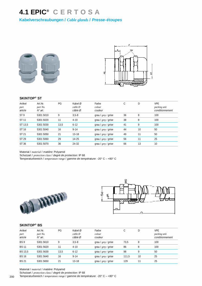
200
SKINTOP® ST
Artikel Art.Nr. PG Kabel Ø Farbe C D VPEpart part No. cable Ø colour packing unitarticle N° art. câble Ø couleur conditionnement
ST 9 5301 5010 9 3,5-8 grau / grey /grise 36 8 100
ST 11 5301 5020 11 4-10 grau / grey /grise 38 8 100
ST 13,5 5301 5030 13,5 6-12 grau / grey /grise 41 9 100
ST 16 5301 5040 16 9-14 grau / grey /grise 44 10 50
ST 21 5301 5050 21 13-18 grau / grey /grise 49 11 50
ST 29 5301 5060 29 14-25 grau / grey /grise 56 11 25
ST 36 5301 5070 36 24-32 grau / grey /grise 66 13 10
Material / material / matière: PolyamidSchutzart / protection class/ degré de protection: IP 68Temperaturbereich / temperature range / gamme de température: -20° C – +80° C
SKINTOP® BS
Artikel Art.Nr. PG Kabel Ø Farbe C D VPEpart part No. cable Ø colour packing unitarticle N° art. câble Ø couleur conditionnement
BS 9 5301 5610 9 3,5-8 grau / grey /grise 73,5 8 100
BS 11 5301 5620 11 4-10 grau / grey /grise 86 8 100
BS 13,5 5301 5630 13,5 6-12 grau / grey /grise 98 9 50
BS 16 5301 5640 16 9-14 grau / grey /grise 111,5 10 25
BS 21 5301 5650 21 13-18 grau / grey /grise 129 11 25
Material / material / matière: PolyamidSchutzart / protection class/ degré de protection: IP 68Temperaturbereich / temperature range / gamme de température: -20° C – +80° C
4.1 EPIC® C E R T O S AKabelverschraubungen / Cable glands/ Presse-étoupes
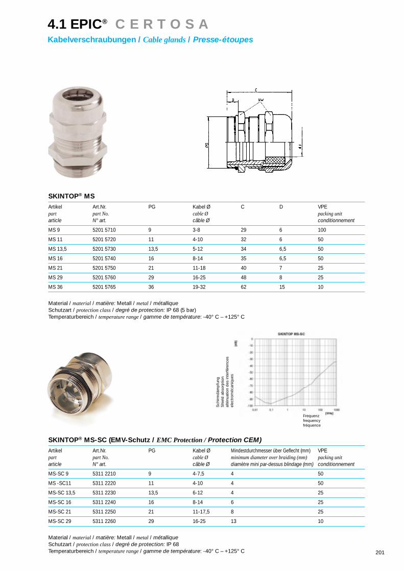
201
SKINTOP® MS
Artikel Art.Nr. PG Kabel Ø C D VPEpart part No. cable Ø packing unitarticle N° art. câble Ø conditionnement
MS 9 5201 5710 9 3-8 29 6 100
MS 11 5201 5720 11 4-10 32 6 50
MS 13,5 5201 5730 13,5 5-12 34 6,5 50
MS 16 5201 5740 16 8-14 35 6,5 50
MS 21 5201 5750 21 11-18 40 7 25
MS 29 5201 5760 29 16-25 48 8 25
MS 36 5201 5765 36 19-32 62 15 10
Material / material / matière: Metall / metal/ métalliqueSchutzart / protection class/ degré de protection: IP 68 (5 bar)Temperaturbereich / temperature range / gamme de température: -40° C – +125° C
SKINTOP® MS-SC (EMV-Schutz / EMC Protection /Protection CEM)
Artikel Art.Nr. PG Kabel Ø Mindestdurchmesser über Geflecht (mm) VPEpart part No. cable Ø minimum diameter over braiding (mm) packing unitarticle N° art. câble Ø diamètre mini par-dessus blindage (mm) conditionnement
MS-SC 9 5311 2210 9 4-7,5 4 50
MS -SC11 5311 2220 11 4-10 4 50
MS-SC 13,5 5311 2230 13,5 6-12 4 25
MS-SC 16 5311 2240 16 8-14 6 25
MS-SC 21 5311 2250 21 11-17,5 8 25
MS-SC 29 5311 2260 29 16-25 13 10
Material / material / matière: Metall / metal/ métalliqueSchutzart / protection class/ degré de protection: IP 68Temperaturbereich / temperature range / gamme de température: -40° C – +125° C
Frequenzfrequencyfréquence
Sch
irmd
ämp
fung
Shi
eld
ab
sorp
tion
alté
nuat
ion
des
inte
rfér
ence
sel
ectr
oméc
aniq
ues
4.1 EPIC® C E R T O S AKabelverschraubungen / Cable glands/ Presse-étoupes

202
SKINDICHT® SK
Artikel Art.Nr. Kabel Ø C D VPEpart part No. cable Ø packing unitarticle N° art. câble Ø conditionnement
SK 9 5200 4230 6-12 16,5 6 50
SK 11 5200 4240 7-15 16,5 6 50
SK 13,5 5200 4250 12-16,5 18,5 7,5 25
SK 16 5200 4260 13-18 19 7,5 25
SK 21 5200 4270 15-23 22,5 8 25
Material / material / matière: Metall / metal/ métalliqueSchutzart / protection class/ degré de protection: IP 20
SKINDICHT® SH
Artikel Art.Nr. Kabel Ø C D VPEpart part No. cable Ø packing unitarticle N° art. câble Ø conditionnement
SH 9 5200 0840 10-12,5 20,5 6 50
SH 11 5200 0850 11-15 21,5 6 50
SH 13,5 5200 0860 14-16,5 24 7,5 25
SH 16 5200 0870 15-18 26 7,5 25
SH 21 5200 0880 18-23,5 29 8 25
SH 29 5200 0890 23-31 33 8 10
SH 36 5200 0900 29-40,5 36,5 9,5 10
Material / material / matière: Metall / metal/ métalliqueSchutzart / protection class/ degré de protection: IP 20
4.1 EPIC® C E R T O S AKabelverschraubungen / Cable glands/ Presse-étoupes

203
SKINDICHT® SR
Artikel Art.Nr. Kabel Ø C D VPEpart part No. cable Ø packing unitarticle N° art. câble Ø conditionnement
SR 09 / 07 5200 1000 5,5-7 52 6 50
SR 11 / 07 5200 1010 5,5-7 56 6 25
SR 11 / 09 5200 1020 7,5-9 56 6 25
SR 13 / 09 5200 1030 7,5-9 62 6,5 25
SR 13 / 11 5200 1040 9-11 62 6,5 25
SR 13 / 13 5200 1050 11-13 62 6,5 25
SR 16 / 13 5200 1060 11,5-13 67 6,5 25
SR 16 / 15 5200 1070 13-15 67 6,5 25
SR 21 / 15 5200 1080 13,5-15 79 7 25
SR 21 / 17 5200 1090 15-17 79 7 25
SR 21 / 19 5200 1100 17-19 79 7 25
SR 21 / 20 5200 1110 18-20 79 7 25
SR 29 / 20 5200 1120 18-20 91 8 10
SR 29 / 23 5200 1130 21-23 91 8 10
SR 29 / 25 5200 1140 23-25 91 8 10
SR 36 / 26 5200 1150 23-26 110 9 5
SR 36 / 30 5200 1160 27-30 110 9 5
Material / material / matière: Metall / metal/ métalliqueSchutzart / protection class/ degré de protection: IP 65Temperaturbereich / temperature range / gamme de température: -40° C – +125° C
4.1 EPIC® C E R T O S AKabelverschraubungen / Cable glands/ Presse-étoupes

204
SKINDICHT® ME (Erweiterung / enlarging /amplificateur)
Artikel Art.Nr. VPEpart part No. packing unitarticle N° art. conditionnement
ME 9 / 11 5200 4000 100
ME 11 / 13,5 5200 4020 100
ME 13,5 / 16 5200 4050 100
ME 16 / 21 5200 4070 50
ME 21 / 29 5200 4090 50
ME 29 / 36 5200 4100 50
ME 36 / 42 5200 4110 10
Material / material / matière: Metall / metal/ métalliqueDIN 46320
SKINDICHT® MR (Reduzierung / reducing /reducteur)
Artikel Art.Nr. VPEpart part No. packing unitarticle N° art. conditionnement
MR 9 / 7 5200 3750 100
MR 11 / 9 5200 3770 100
MR 13,5 / 11 5200 3800 100
MR 16 / 13,5 5200 3840 100
MR 21 / 16 5200 3870 50
MR 29 / 21 5200 3900 50
MR 36 / 29 5200 3930 50
Material / material / matière: Metall / metal/ métalliqueDIN 46320
4.1 EPIC® C E R T O S AKabelverschraubungen / Cable glands/ Presse-étoupes

205
SKINDICHT® BL
Artikel Art.Nr. VPEpart part No. packing unitarticle N° art. conditionnement
BL 7 5200 2680 100
BL 9 5200 3390 100
BL 11 5200 3400 100
BL 13,5 5200 3410 100
BL 16 5200 3420 100
BL 21 5200 3430 100
BL 29 5200 3440 50
BL 36 5200 3450 50
BL 42 5200 3460 50
Material / material / matière: Metall / metal/ métallique
SKINDICHT® BLK
Artikel Art.Nr. VPEpart part No. packing unitarticle N° art. conditionnement
BLK 7 5200 5949 100
BLK 9 5200 5950 100
BLK 11 5200 5960 100
BLK 13,5 5200 5970 100
BLK 16 5200 5980 100
BLK 21 5200 5990 100
BLK 29 5200 6000 100
BLK 36 5200 6010 100
BLK 42 5200 6020 100
Material / material / matière: Polystyrol
4.1 EPIC® C E R T O S AKabelverschraubungen / Cable glands/ Presse-étoupes

207
Die Schutzdeckel von CONTACT aus schlagfe-
stem Kunststoff bieten eine wirksame Abschir-
mung vor Umwelteinflüssen. So sind die
Einsätze im ungesteckten Zustand einfach und
wirkungsvoll geschützt.
CONTACT protective covers, made of impact-
resistant plastic provide effective protection
against environmental influences. In this way,
inserts are easily and effectively protected
when not connected.
Les couvercles de protection de CONTACT en
matière synthétique résistante aux chocs sta-
ble offre un écran efficace contre les in-
tempéries. Ce qui a pour effet de protégér sim-
plement et efficacement les inserts lorsqu’ils
ne sont pas enfichés.
5.1 EPIC® D U C OSchutzdeckel / Protective cover/ Couvercle de protection

208
Technische Daten:• Material: . . . . . . . . . . . . . . . Thermoplast• Temperaturbereich: . . . . . . -40 - +125°C
Technical Data:• Material: . . . . . . . . . . . . . . . . . thermoplastic resin• Temperature range: . . . . . . . . . -40 - +125°C
Caractéristiques techniques:• Materieau: . . . . . . . . . . . . . . plastique thermoformé• Gamme de température: . . . -40 - +125°C
5.1 EPIC® D U C OSchutzdeckel / Protective cover/ Couvercle de protection

209
Schutzdeckel für H-A 3 Gehäuse mit StifteinsatzProtective cover for H-A 3 housings with male insertCouvercle pour boîtiers H-A 3 avec insert mâle
H-A 3
Artikel Art.Nr. Fangschnurpart part No. attachment stringarticle N° art. cordon d’armarage
H-A 3 KDB-S 10430000
H-A 3 KDBF-S 10430400
Schutzdeckel für H-A 3 Gehäuse mit BuchseneinsatzProtective cover for H-A 3 housings with female insert Couvercle pour boîtiers H-A 3 avec insert femelle
H-A 3
Artikel Art.Nr. Fangschnurpart part No. attachment stringarticle N° art. cordon d’armarage
H-A 3 KDB-B 10430300
H-A 3 KDBF-B 10430100*
Schutzdeckel für Anbaughäuse / Sockelgehäuse / KupplungsgehäuseProtective cover for panel mount base / surface mount base / Cable connector hood Couvercle pour embase encastrée / embase en saillie / capot prolongateur
H-A 10-32
Artikel Art.Nr. Fangschnurpart part No. attachment stringarticle N° art. cordon d’armarage
H-A 10 KDB 10457700
H-A 16 KDB 10469700
H-A 32 KDB 10481700
H-A 10 KDBF 10457500*
H-A 16 KDBF 10469500*
H-A 32 KDBF 10481500*
Schutzdeckel für TüllengehäuseProtective cover for hood Couvercle pour capot
H-A 10-32
Artikel Art.Nr. Fangschnurpart part No. attachment stringarticle N° art. cordon d’armarage
H-A 10 KDT 10457800
H-A 16 KDT 10469800
H-A 32 KDT 10481800
H-A 10 KDTF 10457600
H-A 16 KDTF 10469600*
H-A 32 KDTF 10481600*
Gehäuse / Housings/ Boîtiers: 3.1: H-A 3/10/16/32
5.1 EPIC® D U C OSchutzdeckel / Protective cover/ Couvercle de protection
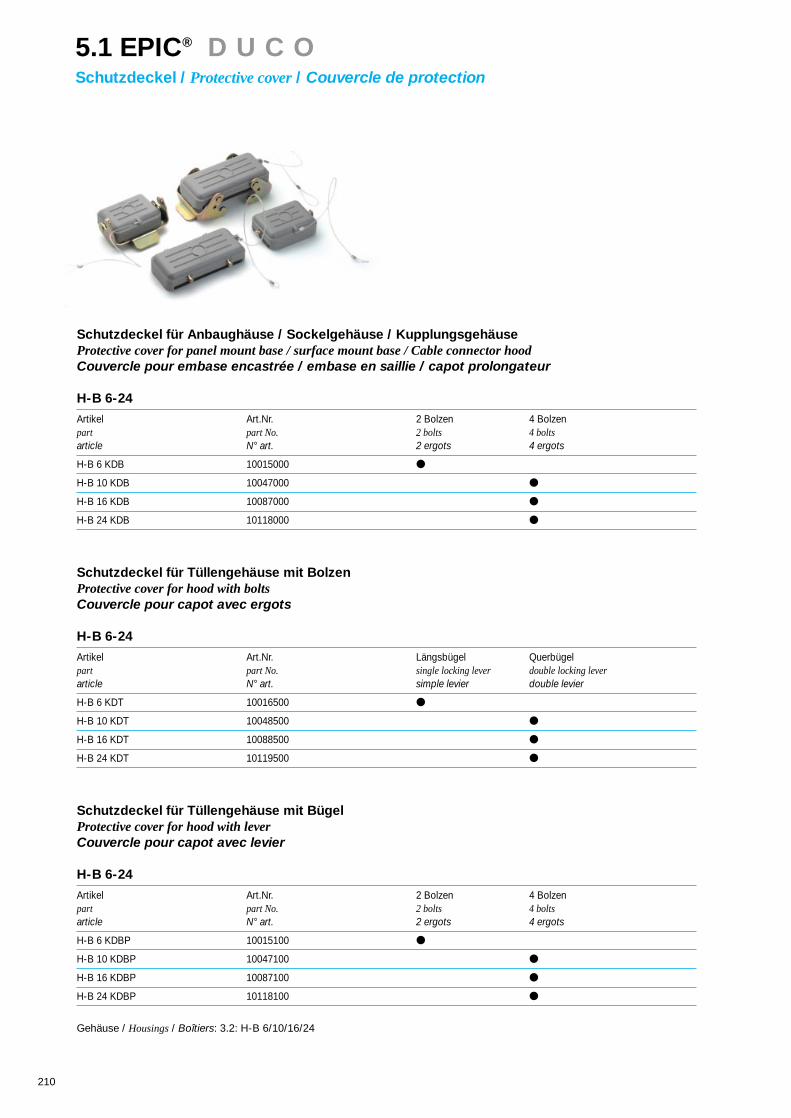
210
Schutzdeckel für Anbaughäuse / Sockelgehäuse / KupplungsgehäuseProtective cover for panel mount base / surface mount base / Cable connector hood Couvercle pour embase encastrée / embase en saillie / capot prolongateur
H-B 6-24
Artikel Art.Nr. 2 Bolzen 4 Bolzenpart part No. 2 bolts 4 boltsarticle N° art. 2 ergots 4 ergots
H-B 6 KDB 10015000
H-B 10 KDB 10047000
H-B 16 KDB 10087000
H-B 24 KDB 10118000
Schutzdeckel für Tüllengehäuse mit BolzenProtective cover for hood with boltsCouvercle pour capot avec ergots
H-B 6-24
Artikel Art.Nr. Längsbügel Querbügelpart part No. single locking lever double locking leverarticle N° art. simple levier double levier
H-B 6 KDT 10016500
H-B 10 KDT 10048500
H-B 16 KDT 10088500
H-B 24 KDT 10119500
Schutzdeckel für Tüllengehäuse mit BügelProtective cover for hood with leverCouvercle pour capot avec levier
H-B 6-24
Artikel Art.Nr. 2 Bolzen 4 Bolzenpart part No. 2 bolts 4 boltsarticle N° art. 2 ergots 4 ergots
H-B 6 KDBP 10015100
H-B 10 KDBP 10047100
H-B 16 KDBP 10087100
H-B 24 KDBP 10118100
Gehäuse / Housings/ Boîtiers: 3.2: H-B 6/10/16/24
5.1 EPIC® D U C OSchutzdeckel / Protective cover/ Couvercle de protection
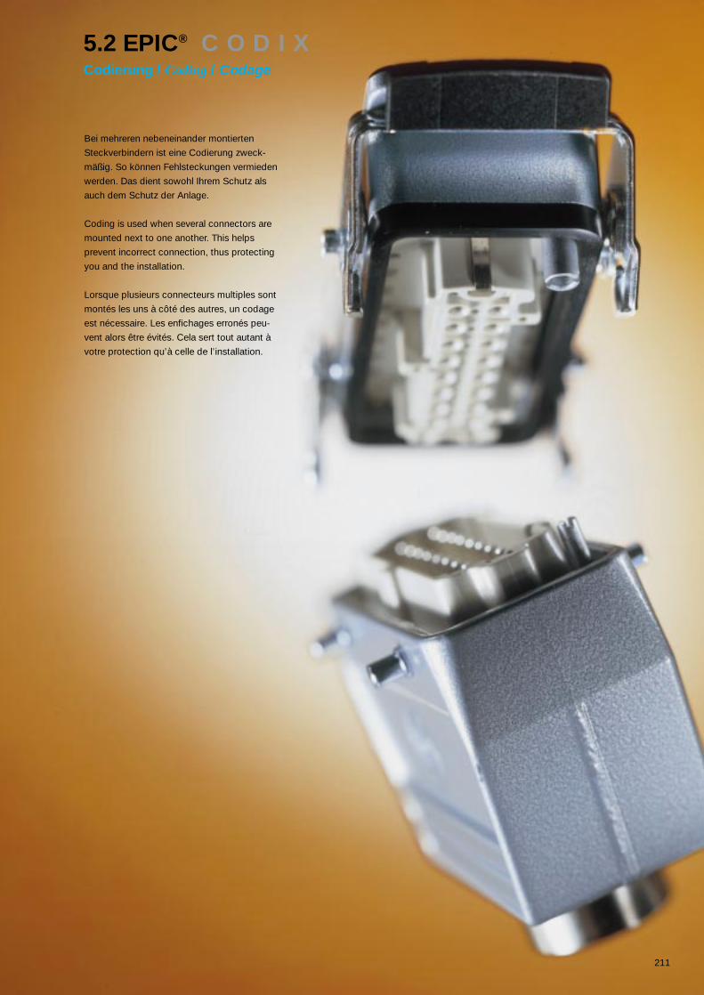
211
Bei mehreren nebeneinander montierten
Steckverbindern ist eine Codierung zweck-
mäßig. So können Fehlsteckungen vermieden
werden. Das dient sowohl Ihrem Schutz als
auch dem Schutz der Anlage.
Coding is used when several connectors are
mounted next to one another. This helps
prevent incorrect connection, thus protecting
you and the installation.
Lorsque plusieurs connecteurs multiples sont
montés les uns à côté des autres, un codage
est nécessaire. Les enfichages erronés peu-
vent alors être évités. Cela sert tout autant à
votre protection qu’à celle de l’installation.
5.2 EPIC® C O D I XCodierung / Coding/ Codage

212
Codierung mit SperrbolzenPolarising with key-pin Détrompage par vis de codage
Artikel Art.Nr. Einsatz VPEpart part No. insert packing unitarticle N° art. insert conditionnement
Codierbolzen / key pin /vis de codage 10019000 H-BE, H-BVE, H-A 50
Codierbolzen / key pin /vis de codage 10019200 H-D 15-128 50
5.2 EPIC® C O D I XCodierung / Coding/ Codage
1 Einsatz / 1 insert /1insert
2 Einsätze / 1 inserts /1insertsCodierbolzenKey pinVis de codage
BefestungsschraubeFixing screwVis de fixation
CodierschemaKey positionsSchéma de codage
M = Stifteinsatz / male insert /insert mâle
F = Buchseneinsatz / female insert /insert femelle

213
Codierung mit Führungsstift und FührungsbuchsePolarization system with guide pin and guide socket Détrompage par broche et douille
Artikel Art.Nr. Einsatz VPEpart part No. insert packing unitarticle N° art. insert conditionnement
Führungsstift / guide pin /broche 11280000 H-D 15-128 50
Führungsbuchse / guide socket /douille 11281000 H-D 15-128 50
Für Anschlußart Crimp- / Schraub- / KäfigzugfederTermination crimp / screw / cage clampRaccordement à setir / à visser / lame de pression
5.2 EPIC® C O D I XCodierung / Coding/ Codage
1 Einsatz / 1 insert /1insert
2 Einsätze / 1 inserts /1insertsFührungsstiftGuide pinBroche
FührungsbuchseGuide socketDouille
BefestigungsschraubenFixing screwVis de fixation
CodierschemaKey positionsSchéma de codage
M = Stifteinsatz / male insert /insert mâle
F = Buchseneinsatz / female insert /insert femelle

214
Codierung mit KontaktverlustPolarization system with contact loss Détrompage à perte de contacts
Artikel Art.Nr. VPEpart part No. packing unitarticle N° art. conditionnement
Codierstift H-D 7/8 / Coding pin H-D 7/8 /Broche H-D 7/8 11162000 100
Codierstift H-A 3/4 / Coding pin H-A 3/4 /Broche H-A 3/4 10451200 50
WerkzeugToolOutillage
Artikel Art.Nr. VPEpart part No. packing unitarticle N° art. conditionnement
Ausdrückwerkzeug H-D 7/8Removal tool H-D 7/8Outil de demontage H-D 7/8 11161200 1
5.2 EPIC® C O D I XCodierung / Coding/ Codage

215
Die Suche nach dem optimalen Bügelsystemhat mit der neuen Da-Vinci Bügelgenerationden krönenden Abschluß gefunden. Die Syn-these aus Raumersparnis, Funktionalität undStabilität. Da-Vinci Perfect ist abnehmbar, arre-tierbar, durch Kunststoffclip leicht zu kenn-zeichnen und das bei bester Ergonomie. Siesparen Platz, denn mit dem Perfect haben Siedie geringsten Schwenkmaße bei garantierterWettbewerbskompatibilität. Wir wollen Ihnenschließlich den Wechsel leicht machen.
The Da-Vinci new generation of locking leversrepresents the crowning glory in the search forthe optimum connector locking system. Theperfect combination of space-saving design,functio-nality and stability. Da-Vinci Perfect isremovable, lockable, easy to identify using aplastic clip, and all combined with the bestpossible ergonomics. You will save space, sin-ce Perfect allows you the smallest possible pi-voting dimensions with guaranteed competitorcompatibility. Ultimately, our aim is to make thechange easy for you.
La recherche d’un système d’étrier optimalvient enfin d’aboutir: la nouvelle générationd’étriers Da-Vinci est un achèvement brillant.
Une synthèsede faible en-
combrement,de fonctionalité
et de robustes-se. Da-Vinci Per-
fect est amovible,verrouillable, facilement
repérable par un clip pla-stique et le tout en parfaite
ergonomie. Vous gagnez de la place,car le Perfect possède une des plus
petites cotes de pivotement et lacompatibilité avec la concurrence
est néanmoins garantie. Nousvoulons vous faciliter l’échan-
ge au maximum.
5.3 EPIC® D A - V I N C I P e r f e c tBügel / Levers/ Leviers

216
Technische Daten• Werkstoff:
Bügel: . . . . . . . . . . . . . . . . . . . . . . . . . . .Stahl/EdelstahlBügelclip: . . . . . . . . . . . . . . . . . . . . . . . .Polyamid
Bezeichnungssystem für Bügel: . . . . . . . . .Fleximark
Technical Data• Material:
Lever: . . . . . . . . . . . . . . . . . . . . . . . . . . . . . . .steel/stainless steel Lever clip: . . . . . . . . . . . . . . . . . . . . . . . . . . . .Polyamide
Lever marking system: . . . . . . . . . . . . . . . . . . . .Fleximark
Caractéristiques techniques• Matériau:
Levier: . . . . . . . . . . . . . . . . . . . . . . . . . . .inox/acier inox Clip levier: . . . . . . . . . . . . . . . . . . . . . . . .Polyamide
clip d’étiquetage: . . . . . . . . . . . . . . . . . . . .Fleximark
Baureihe Schwenkmaß Schwenkmaß Schwenk- Breite BreiteDA-VINCI Perfect Wettbewerb normmaß DA-VINCI Perfect Wettbewerb
Series Pivoting dimension Competitors’ Standard Width Competitors’DA-VINCI Perfect pivoting dimension pivoting dimension DA-VINCI Perfect width
Série Cote de pivotement Cote de pivotement Cote de pivotement Largeur Largeur de laDA-VINCI Perfect de la concurrence normalisée DA-VINCI Perfect concurrence
H-A 10 LB 36,5 36,5 40 71,4 75H-A 16 LB 36,5 36,5 40 87,8 91H-A 32 QB 124,5 126 - 66 69,5H-A 48 QB 136,5 158 - 87,8 99
H-B 6 LB 44 46,5 60 70 73H-B 10 LB 50 57,5 60 88,5 84H-B 16 LB 50 57,5 60 109,5 104,5H-B 24 LB 50 57,5 60 136,5 131H-B 48 LB 105 90 - 139,5 147
H-B 10 QB 116 117 - 53 58H-B 16 QB 136,5 137,5 145 53 58H-B 24 QB 163 164 172 53 58H-B 32 QB 136,5 158 - 87,8 99
5.3 EPIC® D A - V I N C I P e r f e c tBügel / Levers/ Leviers

217
Längsbügel / single locking lever / simple levier H-B 6
Artikel / part / article Art.Nr. / part No. / N° art. Material / material / matériau
H-B 6 LB 10017000* Stahl / steel/ acier
H-B 6 LB-K 10017100* Edelstahl / stainless steel/ inox
Gehäuse / Hoods/ Boîtiers: 3.2
Querbügel-Set / double locking lever / double levierH-B 10, H-B 16, H-B 24
Artikel / part / article Art.Nr. / part No. / N° art. Material / material / matériau
H-B 10-24 QB 10049000* Stahl / steel/ acier
H-B 10-24 QB-K 10049100* Edelstahl / stainless steel/ inox
Gehäuse / Hoods/ Boîtiers: 3.2
5.3 EPIC® D A - V I N C I P e r f e c tBügel / Levers/ Leviers

218
Längsbügel / single locking lever / simple levierH-A 10
Artikel / part / article Art.Nr. / part No. / N° art. Material / material / matériau
H-A 10 LB 10458000* Stahl / steel/ acier
H-A 10 LB-K 10458100* Edelstahl / stainless steel/ inox
Gehäuse / Hoods/ Boîtiers: 3.1
Längsbügel / single locking lever / simple levierH-A 16
Artikel / part / article Art.Nr. / part No. / N° art. Material / material / matériau
H-A 16 LB 10468000* Stahl / steel/ acier
H-A 16 LB-K 10468100* Edelstahl / stainless steel/ inox
Gehäuse / Hoods/ Boîtiers: 3.1
Metallbügel-Clip / lever clip / clip levierH-A, H-B
Artikel / part / article Art.Nr. / part No. / N° art. Material / material / matériau
H-A/H-B Clip 10049500* Plastik / plastic / plastique
Gehäuse / Hoods/ Boîtiers: 3.1 / 3.2
5.3 EPIC® D A - V I N C I P e r f e c tBügel / Levers/ Leviers

Die perfekte Abschirmung gegenüber elektro-magnetischen Störeinflüssen. Einfache Mon-tage, kompatibel zu den Standardgehäusen.Besonders geeignet zum Nachrüsten, für IhreSicherheit.
The perfect shielding against electromagneticinterference. Simple to mount, compatible withstandard housings. Particularly suitable for re-trofitting, for your safety.
La protection parfaite contre les interférencesélectromagnétiques. Simple à monter, compa-tible avec les embases et boîtiers standard.Parfaitement adapté au montage ultérieur pour améliorer votre sécurité.
5.4 EPIC® E L M A CEMV-Schutz / EMC-protection/ Protection CEM
219

220
Technische Daten• Nachrüstbar für: Rechtecksteckverbinder
Rundsteckverbinder
Technical Data• Can be retrofitted to: Rectangular connectors
circular connectors
Caractéristiques techniques• Adaptable sur: Connecteurs rectangulaires
Connecteurs circulaires
Montagevorgang / Directions for use / Instruction de montage
Frequenzfrequencyfréquence
Sch
irmd
ämp
fung
Shi
eld
ab
sorp
tion
alté
nuat
ion
des
inte
rfér
ence
sel
ectr
oméc
aniq
ues
Frequenzfrequencyfréquence
Sch
irmd
ämp
fung
Shi
eld
ab
sorp
tion
alté
nuat
ion
des
inte
rfér
ence
sel
ectr
oméc
aniq
ues
5.4 EPIC® E L M A CEMV-Schutz / EMC-protection/ Protection CEM

221
EMV-Schutz: RechtecksteckverbinderEPIC EMC protection: rectangular connectorsProtection CEM pour EPIC: Connecteurs rectangulaires
H-B: EMV-Kit AnbaugehäuseH-B: EMC kit for panel mount baseH-B: Kit CEM pour embase encastrée
H-B 6
Artikel / part / article Art.Nr. / part No./ N° art.
H-B 6 EMV-AG 70350000
Gehäuse / Hoods/ Boîtiers: 3.2
H-B 10
Artikel / part / article Art.Nr. / part No./ N° art.
H-B 10 EMV-AG 70350100
Gehäuse / Hoods/ Boîtiers: 3.2
H-B 16
Artikel / part / article Art.Nr. / part No./ N° art.
H-B 16 EMV-AG 70350200
Gehäuse / Hoods/ Boîtiers: 3.2
H-B 24
Artikel / part / article Art.Nr. / part No./ N° art.
H-B 24 EMV-AG 70350300
Gehäuse / Hoods/ Boîtiers: 3.2
H-B: EMV-Kit Sockel- / KupplungsgehäuseH-B: EMC kit for surface mount base / cable connector hoodH-B: Kit CEM pour embase en saillie / capot prolongateur
H-B 6
Artikel / part / article Art.Nr. / part No./ N° art.
H-B 6 EMV-SG/TBF 70352000
Gehäuse / Hoods/ Boîtiers: 3.2
5.4 EPIC® E L M A CEMV-Schutz / EMC-protection/ Protection CEM
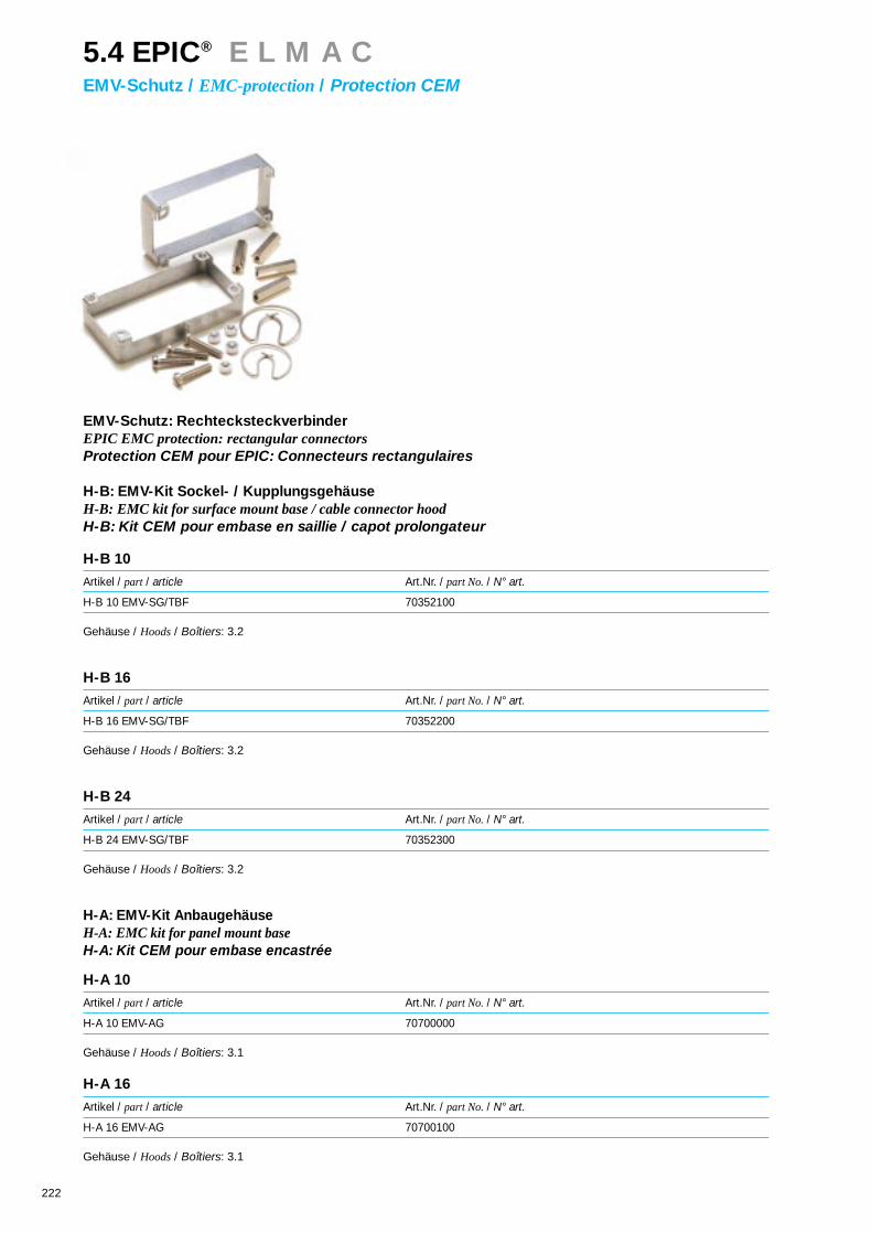
222
EMV-Schutz: RechtecksteckverbinderEPIC EMC protection: rectangular connectorsProtection CEM pour EPIC: Connecteurs rectangulaires
H-B: EMV-Kit Sockel- / KupplungsgehäuseH-B: EMC kit for surface mount base / cable connector hoodH-B: Kit CEM pour embase en saillie / capot prolongateur
H-B 10
Artikel / part / article Art.Nr. / part No./ N° art.
H-B 10 EMV-SG/TBF 70352100
Gehäuse / Hoods/ Boîtiers: 3.2
H-B 16
Artikel / part / article Art.Nr. / part No./ N° art.
H-B 16 EMV-SG/TBF 70352200
Gehäuse / Hoods/ Boîtiers: 3.2
H-B 24
Artikel / part / article Art.Nr. / part No./ N° art.
H-B 24 EMV-SG/TBF 70352300
Gehäuse / Hoods/ Boîtiers: 3.2
H-A: EMV-Kit AnbaugehäuseH-A: EMC kit for panel mount baseH-A: Kit CEM pour embase encastrée
H-A 10
Artikel / part / article Art.Nr. / part No./ N° art.
H-A 10 EMV-AG 70700000
Gehäuse / Hoods/ Boîtiers: 3.1
H-A 16
Artikel / part / article Art.Nr. / part No./ N° art.
H-A 16 EMV-AG 70700100
Gehäuse / Hoods/ Boîtiers: 3.1
5.4 EPIC® E L M A CEMV-Schutz / EMC-protection/ Protection CEM

223
EMV-Schutz: RechtecksteckverbinderEPIC EMC protection: rectangular connectorsProtection CEM pour EPIC: Connecteurs rectangulaires
H-A: EMV-Kit Sockel-/KupplungsgehäuseH-A: EMC kit for surface mount base / cable connector hoodH-A: Kit CEM pour embase en saillie / capot prolongateur
H-A 10
Artikel / part / article Art.Nr. / part No./ N° art.
H-A 10 EMV-SG/TBF 70702000
Gehäuse / Hoods/ Boîtiers: 3.1
H-A 16
Artikel / part / article Art.Nr. / part No./ N° art.
H-A 16 EMV-SG/TBF 70702100
Gehäuse / Hoods/ Boîtiers: 3.1
5.4 EPIC® E L M A CEMV-Schutz / EMC-protection/ Protection CEM
EMV-Schutz: Rundsteckverbinder & Rechtsteckverbinder EMC protection: circular connectors & rectangular connectorsProtection CEM: Connecteurs circulaires & rectangulaires
Artikel Art.Nr. für Rundsteckverbinder mit Anschlußgrößepart part No. for circular connectors sizearticle N° art. pour connecteurs ronds modèle
SAE-7 75000000 PG 7
SAE-9 75000100 PG 9
SAE-11 75000200 PG 11
SAE-13,5 75000300 PG 13,5
SAE-16 75000400 PG 16
Rundsteckverbinderkatalog / circular connector catalogue / Catalogue de connecteurs circulaires

225
Rundsteckverbinder zur Leistungsüber-tragung z.B. an Motoren und Antrieben.Die neue Generation der EPIC® Rund-steckverbinder Serie LS1 ist wahlweiseals bewährte Schraubversion oder alsPush-Pull Variante erhältlich.Bei der Installation der Serie LS1 Rund-steckverbinder kommen Crimp-Kon-takte zum Einsatz, dies gewährleistethöchstmögliche Qualität des An-schlußes, bei gleichzeitiger Reduzie-rung der Installationskosten. Darüber-hinaus bieten die neuen EPIC® Rund-steckverbinder durch eine 360° Schir-manbindung hervorragenden EMV-Schutz. Das neue Design der Kupp-lungsdosen erlaubt sowohl die Verwen-dung von Schraub- als auch von Push-Pull-Steckern, wobei die Steckkompa-tibilität zu allen gängigen Systemen er-halten bleibt.
Circular connector for power transmis-sion e.g. for motors and driving gearThe new generation of EPIC® circularconnectors, series LS1, is optionallyavailable in the traditional screwing ver-sion or as a push-pull variant.For the installation of the series LS1(power) circular connectors, crimpcontacts are used which guarantee thehighest possible quality of the connec-tion, reducing the installation costs atthe same time. In addition, the newEPIC® circular connectors offer out-standing electromagnetic compatibilityprotection through a 360° screenconnection. The new design of thecoupling allows the use of both screwand push-pull connectors, while thecompatibility is maintained for all sys-tems normally used.
Connecteur circulaire pour la transmis-sion de puissance p. ex. aux moteurset aux entraînements.La nouvelle génération des connec-teurs circulaire EPIC® de la série LS1peut être obtenue au choix en versionvissable ou sous sa variante push-pull.Des contacts à sertir sont utilisés pourl’installation de connecteurs circulairede la série LS 1 (puissane). Ceci garan-tit la meilleure qualité de connexionpossible tout en réduisant les coûtsd’installation. En outre, les nouveauxconnecteurs circulaire EPIC® offrentune protection de compatibilité électro-magnétique exceptionnelle grâce à unblindage à 360°. La nouvelle concepti-on des prises permet aussi bien l’utili-sation de connecteurs vissables que deconnecteurs push-pull, la compatibilitéà tous les systèmes courants étantmaintenue.
6.1 EPIC® C I R C O N L S 1Rundsteckverbinder / Circular connector/ Connecteur circulaire

226
Technische Daten:• Polzahlen 5+ PE, 4+3+PE, 5+3+PE• Verschmutzungsgrad 3• Bemessungsspannung 250/800 V, AC• Bemessungsstrom 9/30 A• Prüfspannung: 2,5/6 kV, AC• Temperaturbereich -40°C - +125°C• Schutzart IP 67 gesteckt, DIN 40050• Leitungsanschluß: Crimp 2 mm Kontakte: 0,5-2,5 mm / 2,5-4,0 mm2 Leistung
1 mm Kontakte: 0,06-1,0 mm2 Signal• Durchgangswiderstand (mΩ) < 3• Steckzyklen > 500• Kabeldurchmesser 9-14 mm / 14-17 mm
Material• Gehäuse Zinkdruckguß vernickelt• Isolierkörper PBT nach UL 94 V-0• Kontaktmaterial Kupferlegierung, vergoldet• Dichtungen Viton / H-NBR• Klemmring Messing vernickelt
Technical Data:• Number of contact 5+ PE, 4+3+PE, 5+3+PE• Pollution level 3• Rated voltage 250/800 V, AC• Rated current: 9/30 A• Test voltage: 2,5/6 kV, AC• Temperature range: -40°C - +125°C• Protection class: IP67 mated, DIN 40 050• Wire gauge Crimp 2 mm contacts: 0,5-2,5 mm / 2,5-4,0 mm2 power
1 mm contacts: 0,06-1,0 mm2 signalContact resistance (mΩ) < 3Mating cycles > 500Cable diameter 9-14 mm / 14-17 mm
MaterialHousing Die cast zinc, nickel platedInsulaton body PBT according to UL 94 V-0Gaskets Viton / H-NBRContacts Copper alloy, gold plated
Caractéristiques techniques:Nombre de contacts 5+ PE, 4+3+PE, 5+3+PEDegré de pollution 3Tension nominale 250/800 V, ACCourant nominale: 9/30 ATension d‘essai: 2,5/6 kV, ACGamme de témperature: -40°C - +125°CDegré de protection: IP67 embroché, DIN 40 050Raccordement à sertir 2 mm contacts: 0,5-2,5 mm / 2,5-4,0 mm2 puissance
1 mm contacts: 0,06-1,0 mm2 signal
Résistance de passage (mΩ) < 3 Cycles d‘insertion > 500Diamètre câble 9-14 mm / 14-17 mm
MatièreBoîtier Zinc moulé par injection, nickeléIsolant PBT suivant UL 94 V-0Joints Viton / H-NBRContacts Alliage cuivre, doré
UL,CSA in VorbereitungUL,CSA under preparationPréparation à UL, CSA
6.1 EPIC® C I R C O N L S 1Rundsteckverbinder / Circular connector/ Connecteur circulaire
Frequenzfrequencyfréquence
Sch
irmd
ämp
fung
Shi
eld
ab
sorp
tion
alté
nuat
ion
des
inte
rfér
ence
sel
ectr
oméc
aniq
ues

227
Bauform D6 (Stecker für Buchsenkontakte)Style D6 (Connector for female contacts)Modèle D6 (Connecteur pour contacts femelle)
Artikel Art.Nr. Polbild Kabel-Ø Kontakte VPEpart part No poles cable-Ø contacts packing unitarticle N° art. pôles cable-Ø contacts conditionnement
LS1 D6 5+PE 76020000* 5+PE 9-14 mm 6 x 2 mm (0,5-2,5 mm) 5
LS1 D6 5+PE 76020010 5+PE 9-14 mm 6 x 2 mm (0,5-2,5 mm) 20
LS1 D6 5+PE 76020510 5+PE 9-14 mm _______________ 20
LS1 D6 5+PE 76020710 5+PE 14-17 mm _______________ 20
Artikel Art.Nr. Polbild Kabel-Ø Kontakte VPEpart part No poles cable-Ø contacts packing unitarticle N° art. pôles cable-Ø contacts conditionnement
LS1 D6 4+3+PE 76021000* 4+3+PE 9-14 mm 4 x 2 mm (0,5-2,5 mm) 54 x 1 mm (0,06-1,0 mm)
LS1 D6 4+3+PE 76021010 4+3+PE 9-14 mm 4 x 2 mm (0,5-2,5 mm) 204 x 1 mm (0,06-1,0 mm)
LS1 D6 4+3+PE 76021510 4+3+PE 9-14 mm _______________ 20
LS1 D6 4+3+PE 76021710 4+3+PE 14-17 mm _______________ 20
Artikel Art.Nr. Polbild Kabel-Ø Kontakte VPEpart part No poles cable-Ø contacts packing unitarticle N° art. pôles cable-Ø contacts conditionnement
LS1 D6 5+3+PE 76022000* 5+3+PE 9-14 mm 4 x 2 mm (0,5-2,5 mm) 55 x 1 mm (0,06-1,0 mm)
LS1 D6 5+3+PE 76022010 5+3+PE 9-14 mm 4 x 2 mm (0,5-2,5 mm) 205 x 1 mm (0,06-1,0 mm)
LS1 D6 5+3+PE 76022510 5+3+PE 9-14 mm _______________ 20
LS1 D6 5+3+PE 76022710 5+3+PE 14-17 mm _______________ 20
6.1 EPIC® C I R C O N L S 1Rundsteckverbinder / Circular connector/ Connecteur circulaire
Ansicht steckseitigView from mating sideVue côte de connection
Ansicht steckseitigView from mating sideVue côte de connection
Ansicht steckseitigView from mating sideVue côte de connection
Bauform D6 auch als kurze Bauform erhältlich (64 mm)Style D6 available in a short version (64 mm)Modèle D6 est maintenant dispossible petite (64 mm)
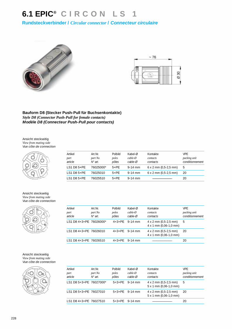
228
Bauform D8 (Stecker Push-Pull für Buchsenkontakte)Style D8 (Connector Push-Pull for female contacts)Modèle D8 (Connecteur Push-Pull pour contacts)
Artikel Art.Nr. Polbild Kabel-Ø Kontakte VPEpart part No poles cable-Ø contacts packing unitarticle N° art. pôles cable-Ø contacts conditionnement
LS1 D8 5+PE 76025000* 5+PE 9-14 mm 6 x 2 mm (0,5-2,5 mm) 5
LS1 D8 5+PE 76025010 5+PE 9-14 mm 6 x 2 mm (0,5-2,5 mm) 20
LS1 D8 5+PE 76025510 5+PE 9-14 mm _______________ 20
Artikel Art.Nr. Polbild Kabel-Ø Kontakte VPEpart part No poles cable-Ø contacts packing unitarticle N° art. pôles cable-Ø contacts conditionnement
LS1 D8 4+3+PE 76026000* 4+3+PE 9-14 mm 4 x 2 mm (0,5-2,5 mm) 54 x 1 mm (0,06-1,0 mm)
LS1 D8 4+3+PE 76026010 4+3+PE 9-14 mm 4 x 2 mm (0,5-2,5 mm) 204 x 1 mm (0,06-1,0 mm)
LS1 D8 4+3+PE 76026510 4+3+PE 9-14 mm _______________ 20
Artikel Art.Nr. Polbild Kabel-Ø Kontakte VPEpart part No poles cable-Ø contacts packing unitarticle N° art. pôles cable-Ø contacts conditionnement
LS1 D8 5+3+PE 76027000* 5+3+PE 9-14 mm 4 x 2 mm (0,5-2,5 mm) 55 x 1 mm (0,06-1,0 mm)
LS1 D8 5+3+PE 76027010 5+3+PE 9-14 mm 4 x 2 mm (0,5-2,5 mm) 205 x 1 mm (0,06-1,0 mm)
LS1 D8 4+3+PE 76027510 5+3+PE 9-14 mm _______________ 20
6.1 EPIC® C I R C O N L S 1Rundsteckverbinder / Circular connector/ Connecteur circulaire
Ansicht steckseitigView from mating sideVue côte de connection
Ansicht steckseitigView from mating sideVue côte de connection
Ansicht steckseitigView from mating sideVue côte de connection

229
Bauform F6 (Kupplung für Stiftkontakte)Style F6 (Coupling for male contacts)Modèle F6 (Prolongateur pour contacts femelle)
Artikel Art.Nr. Polbild Kabel-Ø Kontakte VPEpart part No poles cable-Ø contacts packing unitarticle N° art. pôles cable-Ø contacts conditionnement
LS1 F6 5+PE 76030000* 5+PE 9-14 mm 6 x 2 mm (0,5-2,5 mm) 5
LS1 F6 5+PE 76030010 5+PE 9-14 mm 6 x 2 mm (0,5-2,5 mm) 20
LS1 F6 5+PE 76030510 5+PE 9-14 mm _______________ 20
LS1 F6 5+PE 76030710 5+PE 14-17 mm _______________ 20
Artikel Art.Nr. Polbild Kabel-Ø Kontakte VPEpart part No poles cable-Ø contacts packing unitarticle N° art. pôles cable-Ø contacts conditionnement
LS1 F6 4+3+PE 76031000* 4+3+PE 9-14 mm 4 x 2 mm (0,5-2,5 mm) 54 x 1 mm (0,06-1,0 mm)
LS1 F6 4+3+PE 76031010 4+3+PE 9-14 mm 4 x 2 mm (0,5-2,5 mm) 204 x 1 mm (0,06-1,0 mm)
LS1 F6 4+3+PE 76031510 4+3+PE 9-14 mm _______________ 20
LS1 F6 4+3+PE 76031710 4+3+PE 14-17 mm _______________ 20
6.1 EPIC® C I R C O N L S 1Rundsteckverbinder / Circular connector/ Connecteur circulaire
Ansicht steckseitigView from mating sideVue côte de connection
Ansicht steckseitigView from mating sideVue côte de connection
Hinweis: Bei Verwendung mit Push-Pull Steckern der Bauform D8, muß der Vibrationsschutz/O-Ring vorher entfernt werden – dies hat jedoch keinenEinfluß auf die Dichtigkeitseigenschaften.
Note:For applications with push-pull D8 plug connectors, the vibration protection / o-ring must be removed. This does not have any effect on the sealing properties.
Remarque: Lors de l’emploi de connecteurs à “Push-Pull” de la forme de construction D8, la protection anti-vibrations / le joint torique doit tout d’a-bord être retiré - ceci n’influence cependant en rien les propriétés d’étanchéité.
O-RingO-ringjoint terique

230
Bauform A1 (Einbaudose für Stiftkontakte)Style A1 (Panel mount socket for male contacts)Modèle A1 (Prise encastrée droite pour contacts mâles)
Artikel Art.Nr. Polbild Kontakte VPEpart part No poles contacts packing unitarticle N° art. pôles contacts conditionnement
LS1 A1 5+PE 76000000* 5+PE 6 x 2 mm (0,5-2,5 mm) 5
LS1 A1 5+PE 76000010 5+PE 6 x 2 mm (0,5-2,5 mm) 20
LS1 A1 5+PE 76000510 5+PE _______________ 20
Artikel Art.Nr. Polbild Kontakte VPEpart part No poles contacts packing unitarticle N° art. pôles contacts conditionnement
LS1 A1 4+3+PE 76001000* 4+3+PE 4 x 2 mm (0,5-2,5 mm) 54 x 1 mm (0,06-1,0 mm)
LS1 A1 4+3+PE 76001010 4+3+PE 4 x 2 mm (0,5-2,5 mm) 204 x 1 mm (0,06-1,0 mm)
LS1 A1 4+3+PE 76001510 4+3+PE _______________ 20
Artikel Art.Nr. Polbild Kontakte VPEpart part No poles contacts packing unitarticle N° art. pôles contacts conditionnement
LS1 A1 5+3+PE 76002000* 5+3+PE 4 x 2 mm (0,5-2,5 mm) 54 x 1 mm (0,06-1,0 mm)
LS1 A1 5+3+PE 76002010 5+3+PE 4 x 2 mm (0,5-2,5 mm) 205 x 1 mm (0,06-1,0 mm)
LS1 A1 5+3+PE 76002510 5+3+PE _______________ 20
6.1 EPIC® C I R C O N L S 1Rundsteckverbinder / Circular connector/ Connecteur circulaire
Ansicht steckseitigView from mating sideVue côte de connection
Ansicht steckseitigView from mating sideVue côte de connection
Ansicht steckseitigView from mating sideVue côte de connection
Hinweis: Bei Verwendung mit Push-Pull Steckern der Bauform D8, muß der Vibrationsschutz/O-Ring vorher entfernt werden – dies hat jedoch keinenEinfluß auf die Dichtigkeitseigenschaften.
Note:For applications with push-pull D8 plug connectors, the vibration protection / o-ring must be removed. This does not have any effect on the sealing properties.
Remarque: Lors de l’emploi de connecteurs à “Push-Pull” de la forme de construction D8, la protection anti-vibrations / le joint torique doit tout d’a-bord être retiré - ceci n’influence cependant en rien les propriétés d’étanchéité.
O-RingO-ringjoint torique Montageausschnitt
Panel cut-outDécoupe de montage
M2,5

231
Bauform A2 (Einbaudose gewinkelt 90° für Stiftkontakte)Style A2 (Panel mount socket angled 90° for male contacts)Modèle A2 (Prise encastrée angulaire 90° pour contacts mâle)
Artikel Art.Nr. Polbild Kontakte VPEpart part No poles contacts packing unitarticle N° art. pôles contacts conditionnement
LS1 A2 5+PE 76010000* 5+PE 6 x 2 mm (0,5-2,5 mm) 5
LS1 A2 5+PE 76010010 5+PE 6 x 2 mm (0,5-2,5 mm) 20
LS1 A2 5+PE 76010510 5+PE _______________ 20
Artikel Art.Nr. Polbild Kontakte VPEpart part No poles contacts packing unitarticle N° art. pôles contacts conditionnement
LS1 A2 4+3+PE 76011000* 4+3+PE 4 x 2 mm (0,5-2,5 mm) 54 x 1 mm (0,06-1,0 mm)
LS1 A2 4+3+PE 76011010 4+3+PE 4 x 2 mm (0,5-2,5 mm) 204 x 1 mm (0,06-1,0 mm)
LS1 A2 4+3+PE 76011510 4+3+PE _______________ 20
Artikel Art.Nr. Polbild Kontakte VPEpart part No poles contacts packing unitarticle N° art. pôles contacts conditionnement
LS1 A2 5+3+PE 76012000* 5+3+PE 4 x 2 mm (0,5-2,5 mm) 54 x 1 mm (0,06-1,0 mm)
LS1 A2 5+3+PE 76012010 5+3+PE 4 x 2 mm (0,5-2,5 mm) 205 x 1 mm (0,06-1,0 mm)
LS1 A2 5+3+PE 76012510 5+3+PE _______________ 20
6.1 EPIC® C I R C O N L S 1Rundsteckverbinder / Circular connector/ Connecteur circulaire
Ansicht steckseitigView from mating sideVue côte de connection
Ansicht steckseitigView from mating sideVue côte de connection
Ansicht steckseitigView from mating sideVue côte de connection
Hinweis: Bei Verwendung mit Push-Pull Steckern der Bauform D8, muß der Vibrationsschutz/O-Ring vorher entfernt werden – dies hat jedoch keinenEinfluß auf die Dichtigkeitseigenschaften.
Note:For applications with push-pull D8 plug connectors, the vibration protection / o-ring must be removed. This does not have any effect on the sealing properties.
Remarque: Lors de l’emploi de connecteurs à “Push-Pull” de la forme de construction D8, la protection anti-vibrations / le joint torique doit tout d’a-bord être retiré - ceci n’influence cependant en rien les propriétés d’étanchéité.
M2,5
MontageausschnittPanel cut-outDécoupe de montage
O-RingO-ringjoint terique

232
KontakteContactsContacts
6.1 EPIC® C I R C O N L S 1Rundsteckverbinder / Circular connector/ Connecteur circulaire
Artikel Durchmesser Art.Nr. Version Leiterquerschnitt Anschlußart Für Bauform VPEpart diameter part No. version wire gauge termination for model packing unitarticle diamètre N° art. version section raccordement pour modèle conditionnement
Stift / male/ mâle 1 mm 74030001* 0,06 - 1,0 mm2 Crimp / crimp / à sertir A 1074030000 100
Stift / male/ mâle 2 mm 74031001* 0,5 - 2,5 mm2 Crimp / crimp / à sertir A 1074031000 100
Stift / male/ mâle 2 mm 74032101* 2,5 - 4,0 mm2 Crimp / crimp / à sertir A 1074032100 100
Buchse / 1 mm 74020601* Schlitz / 0,06 - 1,0 mm2 Crimp / crimp / à sertir D 10female/ femelle 74020600* slot / fente 100
Buchse / 1 mm 74020501* Hyper boloid 0,06 - 1,0 mm2 Crimp / crimp / à sertir D 10female/ femelle 74020500 100
Buchse / 2 mm 74031501* Hyper boloid 0,5 - 4,0 mm2 Crimp / crimp / à sertir D 10female/ femelle 74031500 100
Buchse / 2 mm 74032501* Hyper boloid 2,5 - 4,0 mm2 Crimp / crimp / à sertir D 10female/ femelle 74032500 100
Stift / male/ mâle 1 mm 74030101* 0,06 - 1,0 mm2 Crimp / crimp / à sertir F 1074030100 100
Stift / male/ mâle 2 mm 74031101* 0,5 - 2,5 mm2 Crimp / crimp / à sertir F 1074031100 100
Stift / male/ mâle 2 mm 74032001* 2,5 - 4,0 mm2 Crimp / crimp / à sertir F 1074032000 100

233
ZubehörAccessoriesAccessoires
6.1 EPIC® C I R C O N L S 1Rundsteckverbinder / Circular connector/ Connecteur circulaire
Artikel Art.Nr. Für Bauform VPEpart part No. for model packing unitarticle N° art. pour modèle conditionnement
D6 D8 F6 A1 A2
HutstopfenCap plugBouchon 75006010* 20
Klemmring MetallClamp ring metalAnneau métallique 75006610 20
KabelklemmeCable clamp ringJoint de filetageØ 9 - 14 mm 75006910 20
SchirmelementShield ringAnneau protection 75002110 20
º Adapter PG 16Adapter PG 16Adapteur PG 16 75006410 20
Flansch Metall mit DichtungFlange metal with sealBride métallique avec joints 75006310 20
KabelklemmeCable clamp ringJoint de filetageØ 14 - 17 mm 75007210 20
Klemmring MetallClamp ring metalAnneau métallique
KabelklemmeCable clamp ringJoint de filetage
SchirmringShield ringAnneau protection
Adapter MetallAdapter metalAdapteur métallique
HutstopfenCap plugBouchon
º Hinweis: Adapter PG 16: Schutzart abhängig von Kabelverschraubung (4.1)
º Note:Adapter PG 16: Protection class dependant on cable gland (4.1)
º Remarque: Adapteur PG 16: Degré de pollution dépendant de presse-étoupe (4.1)
Flansch MetallFlange metalBride

234
WerkzeugeToolsOutillage
6.1 EPIC® C I R C O N L S 1Rundsteckverbinder / Circular connector/ Connecteur circulaire
º Hinweis: inclusive Positionierer
º Note:Positioner included
º Remarque: avec centreur
Montageschlüssel Assembly keyClé de montage
HakenschlüsselHook spannerClé à crochet
EinführdornInsertion toolMandrin d’insertion
ºº inclusive Positionierer und Locator
ºº Positioner and locator included
ºº avec centreur at insert centreur
Artikel Art.Nr. VPEpart part No. packing unitarticle N° art. conditionnement
Tool-Set LS1/R2.5: 2x Einführdorn / Insertion tool /Mandrin d’insertion (1x LS 1 + 1x R2.5) 75001000* 12x Montageschlüssel / Assembly key /Clé de montage (SW23/26)1x Hakenschlüssel / Hook spanner /Clé à crochet1x Ausbauwerkzeug Isolierkörper / Removal tool insulation body / Outil de demontage isolant ( A1, A2), (R2.5)1x Ausdrückwerkzeug 1mm Kontakte / Removal tool 1mm contact /Outil de demontage 1mm contacts(Bauform / model /modèle A1, A2), (LS1)1x Ausdrückwerkzeug 2mm Kontakte / Removal tool 2mm contact / Outil de demontage 2mm contacts(Bauform / model / modèle A1, A2), (LS1)
ºº Crimpzange / Crimping tool small /Pince à sertir petite0,06 - 1,0 mm2 (1mm Kontakte / contacts / contacts) 75008000* 1
º Crimpzange groß / Crimping tool large / Pince à sertir grande0,34 – 4,0 mm2 (1mm, 2mm Kontakte / contacts /contacts) 75008100* 1
Locator für Crimpzange groß / Locator for crimping tool large / Centreur pour pince à sertir grande1mm Kontakte / contacts /contacts 75008600* 1
Locator für Crimpzange groß / Locator for crimping tool large / Centreur pour pince à sertir grande2mm Kontakte Typ A/D / contacts / contacts 75008700* 1
Locator für Crimpzange groß / Locator for crimping tool large / Centreur pour pince à sertir grande1mm / 2mm Kontakte Typ F / contacts / contacts 75008800* 1
Ersatz-Positionierer für Crimpzange klein / Spare positioner for crimping tool small /Centreur replacement pour pince à sertir petite 75008400* 1
Ersatz-Positionierer für Crimpzange groß / Spare positioner for crimping tool large / Centreur replacement pour pince à sertir grande 75008500* 1
Servicekoffer für Rundsteckverbinder / Service case for circular connectors / Montage set pour connecteurs circulaires 75010000 1
AusdrückwerkzeugRemoval tool Outil de demontage
ServicekofferService caseMontage set

235
6.2 EPIC® C I R C O N R 2 .5Rundsteckverbinder / Circular connector/ Connecteur circulaire
Rundsteckverbinder zur Signalübertragung z.B.
an Knotenpunkten bei BUS-Systemen und
Steuerungen. Die neue Generation der EPIC®
Rundsteckverbinder Serie R2.5 ist wahlweise
als bewährte Schraubversion oder als Push-
Pull Variante erhältlich.
Bei den Rundsteckverbindern der Serie R2.5
(Signal) wird ein patentierter Isolierkörper ver-
wendet, welcher zu allen Gehäuseformen paßt
und sowohl Stift- als auch Buchsenkontakte
aufnehmen kann. Dies ist bei allen Anschlußva-
rianten (Handlöt, Einlöt und Crimp) möglich. Die
Lagerhaltung wird vereinfacht und dadurch Ko-
sten gespart.
Circular connector for signal transmission e.g.
for junctions for BUS-systems and for controls.
The new generation of EPIC® circular connec-
tors series R2.5 is optionally available in the tra-
ditional screwing version or as a push-pull vari-
ant.
In the case of circular connectors from the se-
ries R2.5 (signal), a patented insulation body is
used which fits all housing designs, and can
take both pin and socket contacts in all termi-
nation variants (solder, soldercup and crim-
ping). This simplifies stock-keeping and conse-
quently also saves costs.
Connecteurs circulaire pour la transmission de
signaux p. ex. aux points nodaux de systèmes
BUS et de commandes
La nouvelle génération des connecteurs circu-
laire EPIC® de la série R2.5 peut être obtenue
au choix en version éprouvée vissable ou sous
sa variante push-pull.
Un porte-contacts breveté est utilisé avec les
connecteurs circulaire de la série R2.5 (signal).
Ce isolant est adapté à toutes les formes de
boîtier et accepte aussi bien les contacts mâles
que les contacts femelles et ceci quelles que
soient les variantes de raccordement (soudure
manuelle, soudure et sertissage). Ceci facilite le
stockage et permet ainsi une économie au ni-
veau des coûts.

236
6.2 EPIC® C I R C O N R 2 .5Rundsteckverbinder / Circular connector/ Connecteur circulaire
Technische Daten:• Polzahlen 8+1 9 12 17• Bemessungsspannung (V) AC 160 160 100 (löt) 40 (löt)
160 (crimp) 125 (crimp)• Prüfspannung: (kV) AC 2,5 2,5 1,5 (löt) 1,5
2,5 (crimp)• Verschmutzungsgrad 3• Bemessungsstrom: (A) 9 (1mm Kontakte)
25 (2mm Kontakte)• Temperaturbereich: -40°C - +125°C• Schutzart: IP67 gesteckt, DIN 40050• Leitungsanschluß: Crimp: Kontakt 1mm 0,06-1,0 mm2
Kontakt 2mm 0,5-2,5 mm2
Löt bis 2,5 mm2
Einlöt Ø 1mm; 7,5mm lang• Durchgangswiderstand (mΩ) < 5• Steckzyklen > 500
Material• Gehäuse Zinkdruckguß vernickelt• Isolierkörper PBT nach UL 94 V-0• Dichtungen Viton / H-NBR• Klemmring PA 6,6• Kontakte Kupferlegierung, vergoldet
Technical Data:• Number of contact 8+1 9 12 17 • Rated voltage (V) AC 160 160 100 (solder) 40 (solder)
160 (crimp) 125 (crimp)• Test voltage: (kV) AC 2,5 2,5 1,5 (solder) 1,5
2,5 (crimp)• Pollution level 3• Rated current: (A) 9 (1mm contacts)
25 (2mm contacts)• Temperature range: -40°C - +125°C• Protection class: IP67 mated, DIN 40050• Wire gauge Crimp: contact 1 mm 0,06 - 1,0 mm2
contact 2 mm 0,5 - 2,5 mm2
Solder 2,5 mm2
Solder pin Ø 1mm; 7,5mm length• Contact resistance (mΩ) < 5• Mating cycles > 500
Material• Housing Die cast zinc, nickel plated• Insulation body PBT according to UL 94 V-0• Gaskets Viton / H-NBR• Clamp ring PA 6,6• Contacts Copper alloy, gold plated
Caractéristiques techniques:• Nombre de contacts 8+1 9 12 17• Tension nominale (V) AC 160 160 100 (à souder) 40 (à souder)
160 (à sertir) 125 (à sertir)• Tension d‘essai: (kV) AC 2,5 2,5 1,5 (à souder) 1,5
2,5 (à sertir)
• Degré de pollution 3• Courant nominale: (A) 9 (1mm contacts)
25 (2mm contacts)
• Gamme de témperature: -40°C - +125°C• Degré de protection: IP67 embroché, DIN 40050• Raccordement à sertir: contact 1mm 0,06-1,0 mm2
contact 2mm 0,5-2,5 mm2
à souder 2,5 mm2
à souder sur ci Ø 1mm; 7,5mmlongueur
• Résistance de passage (mΩ) < 5• Cycles d’insertion > 500
Matière• Boîtier Zinc moulé par injection, nickelé• Isolant PBT suivant UL 94 V-0• Joints Viton / H-NBR• Anneau plastique PA 6,6• Contacts Alliage cuivre, doré
UL,CSA in VorbereitungUL,CSA under preparationPréparation à UL, CSA

237
6.2 EPIC® C I R C O N R 2 .5Rundsteckverbinder / Circular connector/ Connecteur circulaire
Bauform D6 Stecker / Style D6 Connector / Modèle D6 Connecteur
Artikel Art.Nr. Kunststoffklemmring Metallklemmring Kabel-Ø VPEpart part No. clamp ring plastic clamp ring metal cable-Ø packing unitarticle N° art. anneau plastique anneau métallique câble-Ø conditionnement
R2.5 D6 5,5-10,5 7204 0000* 5,5-10,5 mm 5
R2.5 D6 5,5-10,5 7204 0010 5,5-10,5 mm 20
R2.5 D6 9-12 7204 0100* 9-12 mm 5
R2.5 D6 9-12 7204 0110 9-12 mm 20
R2.5 D6 5,5-10,5 7204 1000* 5,5-10,5 mm 5
R2.5 D6 5,5-10,5 7204 1010 5,5-10,5 mm 20
R2.5 D6 9-12 7204 1100* 9-12 mm 5
R2.5 D6 9-12 7204 1110 9-12 mm 20
Bauform D8 Stecker Push-Pull SteckerStyle D8 Connector Push-Pull Connector Modèle D8 Connecteur Push-Pull
Artikel Art.Nr. Kunststoffklemmring Metallklemmring Kabel-Ø VPEpart part No. clamp ring plastic clamp ring metal cable-Ø packing unitarticle N° art. anneau plastique anneau métallique câble-Ø conditionnement
R2.5 D8 5,5-10,5 7204 5000* 5,5-10,5 mm 5
R2.5 D8 5,5-10,5 7204 5010 5,5-10,5 mm 20
R2.5 D8 9-12 7204 5100* 9-12 mm 5
R2.5 D8 9-12 7204 5110 9-12 mm 20
R2.5 D8 5,5-10,5 7204 6000* 5,5-10,5 mm 5
R2.5 D8 5,5-10,5 7204 6010 5,5-10,5 mm 20
R2.5 D8 9-12 7204 6100* 9-12 mm 5
R2.5 D8 9-12 7204 6110 9-12 mm 20

238
6.2 EPIC® C I R C O N R 2 .5Rundsteckverbinder / Circular connector/ Connecteur circulaire
Hinweis: Bei Verwendung mit Push-Pull Steckern der Bauform D8, muß der Vibrationsschutz/O-Ring vorher entfernt werden – dies hat jedoch keinenEinfluß auf die Dichtigkeitseigenschaften.Note: For applications with push-pull D8 plug connectors, the vibration protection / o-ring must be removed. This does not have any effect on the sealing properties.Remarque: Lors de l’emploi de connecteurs à “Push-Pull” de la forme de construction D8, la protection anti-vibrations / le joint torique doit tout d’a-bord être retiré - ceci n’influence cependant en rien les propriétés d’étanchéité.
Bauform D7 (Stecker gewinkelt) / Style D7 (Connector angled) / Modèle D7 (Connecteur 90°)
Artikel Art.Nr. Kunststoffklemmring Metallklemmring Kabel-Ø VPEpart part No. clamp ring plastic clamp ring metal cable-Ø packing unitarticle N° art. anneau plastique anneau métallique câble-Ø conditionnement
R2.5 D7 5,5-10,5 7205 0000* 5,5-10,5 mm 5
R2.5 D7 5,5-10,5 7205 0010 5,5-10,5 mm 20
R2.5 D7 9-12 7205 0100* 9-12 mm 5
R2.5 D7 9-12 7205 0110 9-12 mm 20
R2.5 D7 5,5-10,5 7205 0500* 5,5-10,5 mm 5
R2.5 D7 5,5-10,5 7205 0510 5,5-10,5 mm 20
R2.5 D7 9-12 7205 0600* 9-12 mm 5
R2.5 D7 9-12 7205 0610 9-12 mm 20
Bauform F6 Kupplung / Style F6 Coupling / Modèle F6 Prolongateur
Artikel Art.Nr. Kunststoffklemmring Metallklemmring Kabel-Ø VPEpart part No. clamp ring plastic clamp ring metal cable-Ø packing unitarticle N° art. anneau plastique anneau métallique câble-Ø conditionnement
R2.5 F6 5,5-10,5 7206 0000* 5,5-10,5 mm 5
R2.5 F6 5,5-10,5 7206 0010 5,5-10,5 mm 20
R2.5 F6 9-12 7206 0100* 9-12 mm 5
R2.5 F6 9-12 7206 0110 9-12 mm 20
R2.5 F6 5,5-10,5 7206 1000* 5,5-10,5 mm 5
R2.5 F6 5,5-10,5 7206 1010 5,5-10,5 mm 20
R2.5 F6 9-12 7206 1100* 9-12 mm 5
R2.5 F6 9-12 7206 1110 9-12 mm 20
O-RingO-ringjoint terique

239
6.2 EPIC® C I R C O N R 2 .5Rundsteckverbinder / Circular connector/ Connecteur circulaire
Bauform A1 Einbaudose / Style A1 Panel mount socket / Modèle A1 Prise encastrée
Artikel Art.Nr. VPEpart part No. packing unitarticle N° art. conditionnement
R2.5 A1 7200 0000* 5
R2.5 A1 7200 0010 20
Bauform A2 Einbaudose (90°)/ Style A2 Panel mount socket (90°) / Modèle A2 Prise encastrée (90º)
Artikel Art.Nr. VPEpart part No. packing unitarticle N° art. conditionnement
R2.5 A2 7202 0000* 5
R2.5 A2 7202 0010 20
Hinweis: Bei Verwendung mit Push-Pull Steckern der Bauform D8, muß der Vibrationsschutz/O-Ring vorher entfernt werden – dies hat jedoch keinenEinfluß auf die Dichtigkeitseigenschaften.Note:For applications with push-pull D8 plug connectors, the vibration protection / o-ring must be removed. This does not have any effect on the sealing properties.Remarque: Lors de l’emploi de connecteurs à “Push-Pull” de la forme de construction D8, la protection anti-vibrations / le joint torique doit tout d’a-bord être retiré - ceci n’influence cependant en rien les propriétés d’étanchéité.
MontageausschnittPanel cut-outDécoupe de montage
M2,5
M2,5
O-RingO-ringjoint terique
MontageausschnittPanel cut-outDécoupe de montage

240
6.2 EPIC® C I R C O N R 2 .5Rundsteckverbinder / Circular connector/ Connecteur circulaire
Bauform G4 Einbaudose PG 13,5Style G4 Panel mount socket PG 13,5Modèle G4 Prise encastrée PG 13,5
Artikel Art.Nr. VPEpart part No. packing unitarticle N° art. conditionnement
R2.5 G4 7201 0000* 5
R2.5 G4 7201 0010 20
Bauform G5 Einbaudose PG 13,5 mit KontermutterStyle G5 Panel mount socket PG 13,5 with locking nut Modèle G5 Prise encastrée PG 13,5 avec ecrou
Artikel Art.Nr. VPEpart part No. packing unitarticle N° art. conditionnement
R2.5 G5 7211 0000* 5
R2.5 G5 7211 0010 20
Hinweis: Bei Verwendung mit Push-Pull Steckern der Bauform D8, muß der Vibrationsschutz/O-Ring vorher entfernt werden – dies hat jedoch keinenEinfluß auf die Dichtigkeitseigenschaften.Note:For applications with push-pull D8 plug connectors, the vibration protection / o-ring must be removed. This does not have any effect on the sealing properties.Remarque: Lors de l’emploi de connecteurs à “Push-Pull” de la forme de construction D8, la protection anti-vibrations / le joint torique doit tout d’a-bord être retiré - ceci n’influence cependant en rien les propriétés d’étanchéité.

241
6.2 EPIC® C I R C O N R 2 .5Rundsteckverbinder / Circular connector/ Connecteur circulaire
Isolierkörper / Insulation body / Isolant
Ansicht steckseitig Kontakte Isolierkörper Isolierkörper Isolierkörper Kontakte Kontakte VPEunbestückt + Stiftkontakte löt + Buchsenkontakte löt 1 mm 2 mm
view from mating side contacts insulation body + insulation body insulation body + contacts contacts packing unitwithout contacts male contacts solder female contacts solder 1mm 2 mm
vue côte de connection contacts isolant isolant + contacts isolant + contacts contacts contacts conditionnementsans contacts mâle à souder femelle à souder 1 mm 2 mm
8+1 73022100 73012100* 8 1 5
8+1 73002110* 73022110 73012110 8 1 20
9 73023100 73013100* 9 – 5
9 73003110* 73023110 73013110 9 – 20
12 73024100 73014100* 12 – 5
12 73004110* 73024110 73014110 12 – 20
17 73026100 73016100* 17 – 5
17 73006110* 73026110 73016110* 17 – 20
8+1 73022600* 73012600 8 1 5
8+1 73002610* 73022610 73012610 8 1 20
9 73023600* 73013600 9 – 5
9 73003610* 73023610 73013610 9 – 20
12 73024600* 73014600 12 – 5
12 73004610* 73024610 73014610 12 – 20
17 73026600* 73016600 17 – 5
17 73006610* 73026610 73016610 17 – 20
P-T
eil /
P-P
art /
P-P
ièce
Link
sdre
hend
/tu
rnin
g an
ti-cl
ockw
ise
/ rota
tion
à ga
uche
E-Te
il / E
-Par
t /E
-Piè
ceR
echt
sdre
hend
/tu
rnin
g cl
ockw
ise
/ rota
tion
à dr
oite
Hinweis: Isolierkörper sind sowohl für Stift- als auch für Buchsenkontakte geeignet (P-Teil + E-Teil für eine Verbindung verwenden)Note: Insulation bodies are suitable for male and female contacts (use P-Part + E-Part for one connection)Remarque: Isolants sont propre à contacts mâle et femelle (Utilisez P-Pièce + E-Pièce pour un assemblage)

242
6.2 EPIC® C I R C O N R 2 .5Rundsteckverbinder / Circular connector/ Connecteur circulaire
Kontakte / Contacts / Contacts
Artikel Durchmesser Art.Nr. Version Anschlußquerschnitt Anschlußart VPEpart diameter part No. type wire gauge termination packing unitarticle diamètre N° art. type section raccordement conditionnement
Stift / male/ mâle 1 mm 74020000* 0,06 - 1,0 mm2 Crimp / crimp / à sertir 100
Stift / male/ mâle 1 mm 74022000* Löt / solder / à souder 100
Stift / male/ mâle 1 mm 74024000* Einlöt / PCB solder / à souder sur ci 100
Stift / male/ mâle 2 mm 74021000* 0,5 - 2,5 mm2 Crimp / crimp / à sertir 100
Stift / male/ mâle 2 mm 74023000* Löt / solder / à souder 100
Buchse / 1 mm 74020600* Schlitz / 0,06 - 1,0 mm2 Crimp / crimp / à sertir 100
female/ femelle slot / fente
Buchse / 1 mm 74020500* Hyper boloid Crimp / crimp / à sertir 100
female/ femelle
Buchse / 1 mm 74022600* Schlitz / Löt / solder / à souder 100
female/ femelle slot / fente
Buchse / 1 mm 74022500* Hyper boloid Löt / solder / à souder 100
female/ femelle
Buchse / 2 mm 74021600* Schlitz / 0,5 - 2,5 mm2 Crimp / crimp / à sertir 100
female/ femelle slot / fente

243
Baureihe R2.5: Zubehör und ErsatzteileAccessoriesAccessoires
Artikel Art.Nr. Für Bauform VPEpart part No. for model packing unitarticle N° art. pour modèle conditionnement
D6 D7 D8 F6 A1 A2 G4 G5
HutstopfenDust capBouchon 75006010* 20
Klemmring KunststoffClamp ring plasticAnneau plastique 75006510* 20
Klemmring MetallClamp ring metalAnneau metalliqe 75005910* 20
KabelklemmeCable clamp ringJoint de filetageØ 5,5-10,5 mm 75006710* 20
KabelklemmeCable clamp ringJoint de filetageØ 9-12 mm 75006810* 20
SchirmringShield ringAnneau protection 75002010* 20
DistanzhülseDistanceDouille d’écartement 75004010* 20
º Adapter PG 13,5Adapter PG 13,5Adapteur PG 13,5 75006110* 20
Flansch Metall mit DichtungFlange metal with sealBride métallique avec joints 75006210 20
Klemmring KunststoffClamp ring plasticAnneau plastique
KabelklemmeCable clamp ringJoint de filetage
SchirmelementShield ringAnneau protection
HutstopfenDust capBouchon
º Hinweis: Adapter 13,5: Schutzartabhängig von Kabelverschraubung (4.1)
º Note:Adapter PG 13,5: Protection class dependant on cable gland (4.1)
º Remarque: Adapteur PG 13,5: Degré de pollution dépendant de presse-étoupe (4.1)
6.2 EPIC® C I R C O N R 2 .5Rundsteckverbinder / Circular connector/ Connecteur circulaire
DistanzhülseDistance jacketDouille d’écartement
*Adapter PG 13,5* Adapter PG 13,5* Adapteur PG 13,5
Flansch MetallFlange metalBride

244
6.2 EPIC® C I R C O N R 2 .5Rundsteckverbinder / Circular connector/ Connecteur circulaire
WerkzeugeToolsOutillage
º Hinweis: inclusive Positionierer
º Note:Positioner included
º Remarque: avec centreur
Montageschlüssel Assembly keyClé de montage
HakenschlüsselHook spannerClé à crochet
EinführdornInsertion toolMandrin d’insertion
ºº inclusive Positionierer und Locator
ºº Positioner and locator included
ºº avec centreur at insert centreur
Artikel Art.Nr. VPEpart part No. packing unitarticle N° art. conditionnement
Tool-Set LS1/R2.5: 2x Einführdorn / Insertion tool /Mandrin d’insertion (1x R2.5 + 1x LS 1) 75001000* 12x Montageschlüssel / Assembly key /Clé de montage (SW23/26)1x Hakenschlüssel / Hook spanner /Clé à crochet1x Ausbauwerkzeug Isolierkörper / Removal tool insulation body / Outil de demontage isolant ( A1, A2), (R2.5)1x Ausdrückwerkzeug 1mm Kontakte / Removal tool 1mm contact /Outil de demontage 1mm contacts(Bauform / model /modèle A1, A2), (LS1)1x Ausdrückwerkzeug 2mm Kontakte / Removal tool 2mm contact / Outil de demontage 2mm contacts(Bauform / model / modèle A1, A2), (LS1)
ºº Crimpzange klein / Crimping tool small /Pince à sertir petite0,06 - 1,0 mm2 (1mm Kontakte / contacts / contacts) 75008000* 1
º Crimpzange groß / Crimping tool large / Pince à sertir grande0,34 – 4,0 mm2 (1mm, 2mm Kontakte / contacts /contacts) 75008100* 1
Locator für Crimpzange groß / Locator for crimping tool large / Centreur pour pince à sertir grande1mm Kontakte / contacts /contacts 75008600* 1
Locator für Crimpzange groß / Locator for crimping tool large / Centreur pour pince à sertir grande2mm Kontakte / contacts / contacts 75008700* 1
Ersatz-Positionierer für Crimpzange klein / Spare positioner for crimping tool small /Centreur replacement pour pince à sertir petite 75008400* 1
Ersatz-Positionierer für Crimpzange groß / Spare positioner for crimping tool large / Centreur replacement pour pince à sertir grande 75008500* 1
Servicekoffer für Rundsteckverbinder / Service case for circular connectors / Set montage pour connecteurs circulaires 75010000 1
AusdrückwerkzeugRemoval tool Outil de demontage
ServicekofferService caseMontage set
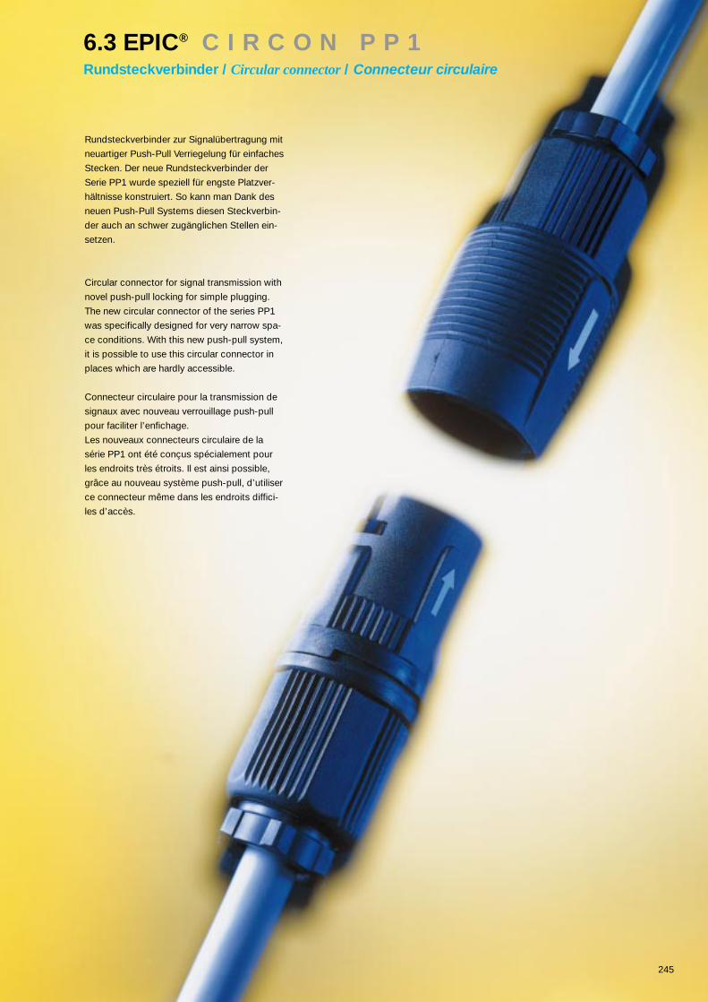
245
6.3 EPIC® C I R C O N P P 1Rundsteckverbinder / Circular connector/ Connecteur circulaire
Rundsteckverbinder zur Signalübertragung mit
neuartiger Push-Pull Verriegelung für einfaches
Stecken. Der neue Rundsteckverbinder der
Serie PP1 wurde speziell für engste Platzver-
hältnisse konstruiert. So kann man Dank des
neuen Push-Pull Systems diesen Steckverbin-
der auch an schwer zugänglichen Stellen ein-
setzen.
Circular connector for signal transmission with
novel push-pull locking for simple plugging.
The new circular connector of the series PP1
was specifically designed for very narrow spa-
ce conditions. With this new push-pull system,
it is possible to use this circular connector in
places which are hardly accessible.
Connecteur circulaire pour la transmission de
signaux avec nouveau verrouillage push-pull
pour faciliter l’enfichage.
Les nouveaux connecteurs circulaire de la
série PP1 ont été conçus spécialement pour
les endroits très étroits. Il est ainsi possible,
grâce au nouveau système push-pull, d’utiliser
ce connecteur même dans les endroits diffici-
les d’accès.

246
6.3 EPIC® C I R C O N P P 1Rundsteckverbinder / Circular connector/ Connecteur circulaire
Technische Daten: • Polzahl 17+2 (17x1mm; 2x2mm)• Verschmutzungsgrad 3• Bemessungsspannung 36 V, AC• Bemessungsstrom 7,5/16 A• Temperaturbereich -25 bis +80° C• Schutzart IP 54 gesteckt nach DIN 40 050• Leitungsanschluß Löt, 0,5 mm2 / 2,5 mm2
• Steckzyklen > 500
Material• Gehäuse PA 6.6• Isolierkörper Glasfaserverstärkter Thermoplast• Kontaktoberfläche Kupferlegierung, vergoldet• Klemmbereich 5 – 12mm
Technical Data:• Number of contacts 17+2 (17x1mm; 2x2mm)• Pollution degree 3• Rated voltage 36 V, AC• Rated current 7,5/16 A• Temperature range -25 bis +80° C• Protection class IP 54 mated, DIN 40 050• Termination Solder, 0,5 mm2 / 2,5 mm2
• Mating cycles > 500
Material• Housing PA 6.6• Insulation body Thermoplast• Contacts Copper alloy, gold plated• Cable diameter 5 – 12mm
Caractéristiques techniques• Nombre de contacts 17+2 (17x1mm; 2x2mm)• Degré de pollution 3• Tension nominale 36 V, AC• Courant nominale 7,5/16 A• Gamme de témperature -25 bis +80° C• Degré de protection IP 54 embroché DIN 40 050• Raccordement à souder, 0,5 mm2 / 2,5 mm2
• Cycles d’insertion > 500
Matière• Boîtier PA 6.6• Isolant Plastique thermoforme• Contacts Alliage cuivre, doré• Diamètre câable 5 – 12mm

247
6.3 EPIC® C I R C O N P P 1Rundsteckverbinder / Circular connector/ Connecteur circulaire
Bauform D inclusive KontakteStyle D, Connector, contacts includedModèle D Connecteur avec contacts
Ansicht steckseitig Artikel Version Art.Nr. Verschraubung VPEview form mating side part version part No. cable gland packing unitvue côte de connection article version N° art. presse-étoupe conditionnement
Push-Pull Stift / male/ mâle 14281500 PG 11 5
Push-Pull Buchse / female/ femelle 14281000 PG 11 5
Bauform F Kupplung inclusive KontakteStyle F, Cable connector, contacts includedModèle F Prolongateur avec contacts
Ansicht steckseitig Artikel Version Art.Nr. Verschraubung VPEview form mating side part version part No. cable gland packing unitvue côte de connection article version N° art. presse-étoupe conditionnement
Push-Pull Stift / male/ mâle 14282000 PG 11 5
Push-Pull Buchse / female/ femelle 14282500 PG 11 5

248
6.3 EPIC® C I R C O N P P 1Rundsteckverbinder / Circular connector/ Connecteur circulaire
Bauform F1 Kupplung inclusive KontakteStyle F1, Cable connector, contacts includedModèle F1 Prolongateur avec contacts
Ansicht steckseitig Artikel Version Art.Nr. Verschraubung VPEview form mating side part version part No. cable gland packing unitvue côte de connection article version N° art. presse-étoupe conditionnement
Push-Pull Stift / male/ mâle 14283000 PG 11 5
Push-Pull Buchse / female/ femelle 14283500 PG 11 5
Bauform A Einbaudose inclusive KontakteStyle A, Panel mount base, contacts includedModèle A Prise encastrée avec contacts
Ansicht steckseitig Artikel Version Art.Nr. VPEview form mating side part version part No. packing unitvue côte de connection article version N° art. conditionnement
Push-Pull Stift / male/ mâle 14280000 5
Push-Pull Buchse / female/ femelle 14280500 5

249
6.4 EPIC® C I R C O N R 3 .0Rundsteckverbinder / Circular connector/ Connecteur circulaire
Die Rundsteckverbinder Serie R3.0 sind
eine Alternative zur Serie R2.5, insbeson-
dere dort wo höhere Polzahlen gefordert
sind. Die Serie R3.0 ist erhältlich in den
Polzahlen 21 und 26.
The circular connector series R3.0 is an
alternative to the series R2.5, especially
where higher numbers of contacts are re-
quired. The series R3.0 is available with
21 and 26 contacts.
Les connecteurs circulaire de la série R3.0 re-
présentent une alternative à la série R2.5 là où
un nombre de pôles plus élevé est exigé. La
série R3.0 est disponible en 21 et 26 contacts.

250
6.4 EPIC® C I R C O N R 3 .0Rundsteckverbinder / Circular connector/ Connecteur circulaire
Technische Daten:• Polzahlen 21, 26• Bemessungsspannung 60 V, AC• Prüfspannung: 1,5 kV, AC• Verschmutzungsgrad 2• Bemessungsstrom: 7,5 A
• Temperaturbereich: -40°C - +125°C• Schutzart: IP 65...IP67 gesteckt,
DIN 40 050Verschraubungsabhängig
• Leitungsanschluß: Löt bis 1mm2
Einlöt Ø 1mm; 3,7 – 4,7mm lang
• Durchgangswiderstand < 3 (mΩ)• Steckzyklen > 500
Material• Gehäuse Kupferlegierung vernickelt• Isolierkörper Thermoplast UL 94 V-0• Dichtungen Neopren• Kontakte Kupferlegierung, vergoldet
Technical Data:• Number of contacts 21, 26• Rated voltage 60 V, AC• Test voltage: 1,5 kV, AC• Pollution level 2• Rated current: 7,5 A
• Temperature range: -40°C - +125°C• Protection class: IP 65...IP67 mated, DIN 40 050
Dependant on cable gland• Wire gauge Solder up to 1mm2
PCB solder Ø 1mm; 3,7 – 4,7mm long
• Contact resistance < 5 (mΩ)• Mating cycles > 500
Material• Housing Copper alloy, nickel plated• Insulaton body thermopast according to UL 94 V-0• Gaskets Neopren• Contacts Copper alloy, gold plated
Caractéristiques techniques:• Nombre de contacts 21, 26
• Tension nominale 60 V, AC• Tension d‘essai: 1,5 kV, AC• Degré de pollution 2• Courant nominale: 7,5 A
• Gamme de témperature: -40°C - +125°C• Degré de protection: IP 65...IP67 embroché,
DIN 40 050Dépendand de presse-étoupe
• Raccordement à souder 1,0 mm2
à souder sur ci Ø 1mm; 3,7 - 4,7mm longue
• Résistance de passage < 5 (mΩ)• Cycles d‘insertion > 500
Matière• Boîtier Alliage cuivre, nickelé• Isolant Plastique thermoformé
UL 94 V-0• Joints Neopren• Contacts Alliage cuivre, doré

251
6.4 EPIC® C I R C O N R 3 .0Rundsteckverbinder / Circular connector/ Connecteur circulaire
Bauform D6 (Stecker, Kabelverschraubung)Style D6 (Connector, cable gland)Modèle D6 (Connecteur, presse-étoupe)
Artikel Art.Nr. Codierung VPEpart part No. Coding packing unitarticle N° art. Codage conditionnement
BF D6 202040AF N 10
Bauform D6 (Kupplung, Kabelverschraubung)Style D6 (Cable connector, cable gland)Modèle D6 (Prolongateur, presse-étoupe)
Artikel Art.Nr. Codierung VPEpart part No. Coding packing unitarticle N° art. Codage conditionnement
BF F6 202050AF N 10
Hinweis: Beispiel für Bestellung (Gehäuse + Isolierkörper -> 202010AA + 40200121)
Note:Example for order (Housing + Insulation body -> 202010AA + 40200121)
Remarque: Exemple pour commande (Boîtier + isolant-> 202010AA + 40200121)

252
6.4 EPIC® C I R C O N R 3 .0Rundsteckverbinder / Circular connector/ Connecteur circulaire
Bauform A Einbaudose (Frontmontage)Style A panel mount base (front assembly)Modèle A prise encastrée (montage frontal)
Artikel Art.Nr. Codierung VPEpart part No. Coding packing unitarticle N° art. Codage conditionnement
BF A 202010AA N 10
Bauform B2 Einbaudose (Hinterwandmontage)Style B2 panel mount base (back-wall assembly)Modèle B2 prise encastrée (montage sur paroi arrières)
Artikel Art.Nr. Codierung VPEpart part No. Coding packing unitarticle N° art. Codage conditionnement
BF B2 202030AA N 10
Hinweis: Beispiel für Bestellung (Gehäuse + Isolierkörper -> 202010AA + 40200121)
Note:Example for order (Housing + Insulation body -> 202010AA + 40200121)
Remarque: Exemple pour commande (Boîtier + isolant-> 202010AA + 40200121)

253
6.4 EPIC® C I R C O N R 3 .0Rundsteckverbinder / Circular connector/ Connecteur circulaire
Bauform G1 Einbaudose (Einlochmontage)Style G1 panel mount base (single hole assembly)Modèle G1 prise encastrée (prise avec écrou de fixation)
Artikel Art.Nr. Codierung VPEpart part No. Coding packing unitarticle N° art. Codage conditionnement
BF A 202060AA N 10
Hinweis: Beispiel für Bestellung (Gehäuse + Isolierkörper -> 202010AA + 40200121)
Note:Example for order (Housing + Insulation body -> 202010AA + 40200121)
Remarque: Exemple pour commande (Boîtier + isolant-> 202010AA + 40200121)

254
Isolierkörper / Insulation body / Isolant
Ansicht steckseitig Kontakte Isolierkörper Isolierkörper Isolierkörper Isolierkörper Für Bauform VPE+ Stiftkontakte löt + Buchsenkontakte löt Stiftkontakte einlöt Buchsenkontakte einlöt
view from mating side contacts insulation body + insulation body + insulation body + insulation body + for model packing unitmale contacts solder female contacts soldermale contacts PCB solder female contacts PCB solder
vue côte de connection contacts isolant + contacts isolant + contacts isolant + contacts isolant + contacts pour modèle condition-mâle à souder femelle à souder mâle à souder sur ci femelle à souder sur ci nement
21 40250121 A/B/D/F/G 10
21 40264121 A/B 10
26 40250126 A/B/D/F/G 10
26 40264126 A/B 10
21 40200121 A/B/D/F/G 10
21 40212121 A/B 10
26 40200126 A/B/D/F/G 10
26 40212126 A/B 10
P-T
eil /
P-P
art /
P-P
ièce
Link
sdre
hend
/tu
rnin
g an
ti-cl
ockw
ise
/ rota
tion
à ga
uche
E-Te
il / E
-Par
t /E
-Piè
ceR
echt
sdre
hend
/tu
rnin
g cl
ockw
ise
/ rota
tion
à dr
oite
Hinweis: Beispiel für Bestellung (Gehäuse + Isolierkörper -> 202010AA + 40200121)
Note:Example for order (Housing + Insulation body -> 202010AA + 40200121)
Remarque: Exemple pour commande (Boîtier + isolant-> 202010AA + 40200121)
6.4 EPIC® C I R C O N R 3 .0Rundsteckverbinder / Circular connector/ Connecteur circulaire
26 contacts
21 contacts

255
6.4 EPIC® C I R C O N R 3 .0Rundsteckverbinder / Circular connector/ Connecteur circulaire
Zubehör und ErsatzteileAccessoriesAccessoires
Artikel Art.Nr. Für Bauform VPEpart part No. for model packing unitarticle N° art. pour modèle conditionnement
A1 B2 D6 F6 G1
Flanschdichtung 50201203 10Flat gasket 50202203 10Joint plat
Dichtring 50206204 10Sealing ringAnneau d’etanchéité
Metallschraubkappe 50201120 10Metal screw cap 50203120 10Bouchon d’étanchéité 50204121 10
50205121 1050206125 10
Winkelgehäuse 502012AC 10Angled housingBoîtier á 90º degré
Montage/Werkzeug 50200800 1Assembly toolQutil assemblage

257
7.1 EPIC® B U SInterbusanwendung / INTERBUS application/ Système INTERBUS
Steuerungen werden immer komplexer, das er-
fordert sichere Übertragungslösungen. Dafür
wurde das neue EPIC LWL-System entwickelt.
Es bietet alle Vorteile der modernen Lichtwellen-
leitertechnik verbunden mit den bewährten
EPIC-Standards, im Modul-System, im klassi-
schen Rechtecksteckverbinder und im neuen
Rundsteckverbinder mit im Stecker integrierten
Optokoppler.
Control systems are becoming ever more com-
plex, which means that reliable transmission
solutions are required. The new EPIC optical fi-
bre system was developed for this very purpo-
se, offering all the advantages of modern opti-
cal fibre technology combined with the tried
and tested EPIC standards, in a modular sys-
tem, in the conventional rectangular connector
and in the new circular connector with opto-
coupler integrated into them.
Les automatismes deviennent de plus en plus
complexes, cela exige des moyens de trans-
mission sûrs. C’est pourquoi nous avons conçu
le nouveau système EPIC pour fibres optiques.
Il offre tous les avantages de la transmission
par fibre optique, dans le cadre des connexions
standard EPIC. Modulaire,
le système se monte dans les connecteurs
rectangulaires classiques et les nouveaux con-
necteurs circulaire - avec optocoupleur intégré.

258
Technische DatenINTERBUS• Lichtwellenleiter Steckverbindersystem• Schnittstelle: . . . . . . . . . . . . . . .RS 485• Schutzart: . . . . . . . . . . . . . . . . .IP 65• Temperaturbereich: . . . . . . . . . .-20°C – +85°CÜbertragungsparameter• Wellenlänge: . . . . . . . . . . . . . . .660 nm• Übertragungslänge: . . . . . . . . .40 m• Übertragungsrate: . . . . . . . . . . .0 - 500 kBit/s• Kontaktzahl: . . . . . . . . . . . . . . . .9/8+1
Lichtwellenleiter für Modulares System• für Fasertyp: . . . . . . . . . . . . . . . .Kunststoff-Faser: . .(POF)
Durchmesser: . . . .1 mmWellenlänge: . . . . .660 nm
Technical DataINTERBUS
• Optical fibre connector system• Interface: . . . . . . . . . . . . . . . . . . . .RS 485• Protection class: . . . . . . . . . . . . . . .IP 65• Temperature range: . . . . . . . . . . . . .-20°C – +85°CTransmission parameters• Wavelength: . . . . . . . . . . . . . . . . . .660 nm• Transmission distance: . . . . . . . . . .40 m• Transmission rate: . . . . . . . . . . . . .0 - 500 kBit/s• Number of contacts: . . . . . . . . . . . .9/8+1
Optical fibres for Modular System• for fibre type: . . . . . . . . . . . . . . . . . .plastic fibre: . . . . . . .(POF)
diameter: . . . . . . . . .1 mmwavelength: . . . . . . .660 nm
Caractéristiques techniquesINTERBUS• Connecteurs pour fibres optiques• Interface: . . . . . . . . . . . . . . . . . .RS 485• Degré de protection: . . . . . . . . .IP 65• Gamme de température: . . . . . .-20°C – +85°CParamètres de transmission• Longueur d’onde: . . . . . . . . . . .660 nm• Longueur de transmission: . . . .40 m• Vitesse de transmission: . . . . . .0 - 500 kBit/s• Nombre de contacts: . . . . . . . . .9/8+1
Fibre optique pour système modulaire• Type de fibre: . . . . . . . . . . . . . . .Fibre en plastique: .(POF)
Diamètre: . . . . . . . .1 mmLongueur d’onde: .660 nm
7.1 EPIC® B U SInterbusanwendung / INTERBUS application/ Système INTERBUS

259
INTERBUS
Rundsteckverbinder / RundsteckverbinderCircular connector / circular connectorConnecteur circulaire / connecteur circulaire
Artikel Version Art.Nr. Kabellänge Lpart version part No. cable length Larticle version N° art. longeur de cable L
INTERBUS L=2 R/R Rund Buchse - Rund Stift / circular female - circular male
femelle circulaire - mâle circulaire 13091000 2 m
LWL INTERBUS L=5 R/R Rund Buchse - Rund Stift / circular female - circular male
femelle circulaire - mâle circulaire 13091100 5 m
LWL INTERBUS L=10 R/R Rund Buchse - Rund Stift / circular female - circular male
femelle circulaire - mâle circulaire 13091200 10 m
LWL INTERBUS L=20 R/R Rund Buchse - Rund Stift / circular female - circular male
femelle circulaire - mâle circulaire 13091300 20 m
7.1 EPIC® B U SInterbusanwendung / INTERBUS application/ Système INTERBUS

260
7.1 EPIC® B U SInterbusanwendung / INTERBUS application/ Système INTERBUS
INTERBUS
Rundsteckverbinder / Sub-DCircular connector / Sub-DConnecteur circulaire / Sub-D
Artikel Version Art.Nr. Kabellänge Lpart version part No. cable length Larticle version N° art. longeur de cable L
LWL INTERBUS L=2 R/Sub-D Rund Stift - Sub-D Buchse / circular male - Sub-D female
mâle circulaire - femelle Sub-D 13092000 2 m
LWL INTERBUS L=5 R/Sub-D Rund Stift - Sub-D Buchse / circular male - Sub-D female
mâle circulaire - femelle Sub-D 13092100 5 m
LWL INTERBUS L=10 R/Sub-D Rund Stift - Sub-D Buchse / circular male - Sub-D female
mâle circulaire - femelle Sub-D 13092200 10 m
LWL INTERBUS L=20 R/Sub-D Rund Stift - Sub-D Buchse / circular male - Sub-D female
mâle circulaire - femelle Sub-D 13092300 20 m
LWL INTERBUS L=2 Sub-D/R Sub-D Stift - Rund Buchse / Sub-D male - circular female
mâle Sub-D - femelle circulaire 13093000 2 m
LWL INTERBUS L=5 Sub-D/R Sub-D Stift - Rund Buchse / Sub-D male - circular female
mâle Sub-D - femelle circulaire 13093100 5 m
LWL INTERBUS L=10 Sub-D/R Sub-D Stift - Rund Buchse / Sub-D male - circular female
mâle Sub-D - femelle circulaire 13093200 10 m
LWL INTERBUS L=20 Sub-D/R Sub-D Stift - Rund Buchse / Sub-D male - circular female
mâle Sub-D - femelle circulaire 13093300 20 m

261
7.1 EPIC® B U SInterbusanwendung / INTERBUS application/ Système INTERBUS
INTERBUS
Sub-D / Sub-DSub-D / Sub-DSub-D / Sub-D
Artikel Version Art.Nr. Kabellänge Lpart version part No. cable length Larticle version N° art. longeur de cable L
LWL INTERBUS L=2 Sub-D/Sub-D Sub-D Buchse - Sub-D Stift / Sub-D female - Sub-D male
femelle Sub-D - mâle Sub-D 13094000 2 m
LWL INTERBUS L=5 Sub-D/Sub-D Sub-D Buchse - Sub-D Stift / Sub-D female - Sub-D male
femelle Sub-D - mâle Sub-D 13094100 5 m
LWL INTERBUS L=10 Sub-D/Sub-D Sub-D Buchse - Sub-D Stift / Sub-D female - Sub-D male
femelle Sub-D - mâle Sub-D 13094200 10 m
LWL INTERBUS L=20 Sub-D/Sub-D Sub-D Buchse - Sub-D Stift / Sub-D female - Sub-D male
femelle Sub-D - mâle Sub-D 13094300 20 m

264
I. General Terms
1. For the conclusion of a contract of sale and scope of supply commitments re-sulting from this conclusion it is relevant that both contracting parties makecorresponding declarations of intention in writing. Should such written decla-rations of intention be absent the only written acknowledgement of order ofsupplier will be legally binding. In this connection the conditions of sale anddelivery mentioned below are applied as agreed upon.
2. All deliveries and performances – henceforth as well – of CONTACT GmbH in-cluding additional performances such as consultancy before and after con-clusion are exclusively effected by virtue of the following conditions, also forany kind of business of adjustment. The buyer´s conditions of purchase arehereby contradicted. They do not engage CONTACT either if we do not cont-radict again when the contract is concluded. It is understood that the generalconditions of delivery and payment are accepted by receipt ofour goods atthe latest.
3. Offers of CONTACT GmbH are not binding. Conclusions and agreements –especially as far as they differ from our conditions – will not be binding for usuntil they are confirmed by us in writting.
4. These conditions are also applied for sales on the basis of trade terms, espe-cially those of Incoterms. For sales on the basis of one of these contract for-mula of Incoterms those Incoterms as may from time be established are rele-vant. However, the trade terms are only applied in so far as there are not takenany other regulations in these conditions or in particular agreements.
II. Scope and Duty to Deliver
1. Documents, illustartions, drawings and indications of weight belonging to theoffer of CONTACT GmbH, only prevail approximately. Modifications of eachkind will be reserved in the interest of technical progress, the latest experien-ces and improvements. Exceptions need to be confirmed in written form.CONTACT explicitly reserves the right of ownership and copyright of all docu-ments. Offers and documents belonging to them must not be accessible tothird parties without our written consent. By request these documents, dra-wings, samples, etc. belonging to the offer have to be given back immediate-ly.
2. In case of special manufacturing a variation of + 10 percent of the requiredquantity are binding for the purchaser. This is also applicable for partial quan-tities.
III. Pricing
1. In case of delivery prices are only applicable for the respective order confir-med ex works excluding packing as far as nothing else has been determinedin writing. In case of general changes of production costs until delivery dayCONTACT GmbH reserves the right to price corrections. Proces are under-stood plus legal VAT.
2. If no other arrangements are made, samples will only be delivered if they arecharged. All samples remain CONTACT´s property until they are fully paid.
3. We reserve the right to surcharge increased costs of materials by correlating itwith the quotation of raw materials at tat time. If unforreseeable increases ari-se in labour or transport costs, taxes or charges between conclusion of con-tract and delivery, CONTACT is entitled to make a price adjustment accordingto these factors.
4. The minimum order value is DM 500,– net.
IV. Reservation of Ownership
1. The objects of deliveries (including conditional commodities) remainCONTACT´s property until all claims due against the buyer and resulting frombuisness contracts, are satisfied. As far as the value of all security rights dueto CONTACT GmbH exceeds the amount of all secured claims by more than20 percent CONTACT will release a respective part of security rights by re-quest of the purchaser.
2. As long as reservation of ownership exists, pledge or assignment by bill of sa-le are forbidden to the buyer and resale is only permitted by resellers will bepaid by this customer or will reserve the right that property does not go overto the customer until the latter has completely satisfied his liabilities to pay.
3 a) If the purchaser resells conditional commodities he will already, for reasonsof security, assign his future claims to CONTACT resulting from the resale to-wards his customers, with all subsidiary rights – including any claims of balan-ce, without the need of further special declarations. If conditional commodityis resold together with other objects without agreeing on a price per unit forthe conditional commodity the purchaser transfers to the supplier Contactthat part of total price required which corresponds to the price of conditionalcommodity charged by the supplier and by giving that part priority over remai-ning claims.
b) In case of satisfactory proof of a legitimate interest the purchaser has to gi-ve the necessary informations and to hand over the required documents tothe supplier CONTACT GmbH to be able to assert his rights towards the cu-stomer.
c) Until revoked the purchaser is entitled to collect assigned debts resultingfrom resale. In case of an important reason, especially in case of default ofpayment, stoppage of payment, opening of a procedure of insolvency (bank-ruptcy, settlement, total execution), bill protest or if there are comparable ju-stified indications which give notice of insolvency of the purchaser, the sup-plier is entitled to revoke the purchaser´s authority to collect. Besides, afterprevious threat of disclosing assignment for security or realizing assigneddebts and by observing an appropriate period, the supplier can disclose as-
signment for security, realize assigned debts as well as require disclosure ofassignment for security by the purchaser towards the customer.
4 a) The purchaser is permitted to process or transform conditional commodity orcombine it with other objects. Processing, transformation or combination isdone for the supplier CONTACT GmbH. The purchaser holds in safe custodythe new object for the supplier CONTACT GmbH with the care of a prudentbuisness man. The processed, transformed or combined object is regardedas conditional commodity.
b) In case of processing, transformation or combination with other objects notbelonging to CONTACT, CONTACT GmbH is entitled to joint ownership of thenew object with a share resulting from the proportion of value of the proces-sed, transformed or combined conditional commodity to the value of the re-mainingprocessed commodity at the moment of processing commodity at themoment of processing, transformation or combination. Provided that thepurchaser acquires sole ownership of the new object, the supplier CONTACTGmbH and the purchaser agree that the purchaserconcedes to the supplierCONTACT join ownership of the new object created by processing, transfor-mation or combinationin relation of the value of the processed, transformed orcombined conditional commodity to the remaining processed, transformed orcombined commodity at the moment of processing, transformation or combi-nation.
c) In case the new object should be sold the purchaser will transfer to the sup-plier CONTACT GmbH his claim from resale against the customer with allsub-sidiary rights for reasons of security without the need of further special decla-rations. However, the assignment only appliesto the value of the amountwhich corresponds to the value of processed, transformed or combined con-ditional commodity charged to the supplier CONTACT GmbH. The part ofclaim transferred to the supplier CONTACT GmbH has to be satisfied prefe-rentially. With respect to the authority to collect as well as the conditions foryour revocation number 3.c) is applicable accordingly.
d) If conditional commodity is combined with properties or movables by thepurchaser, the purchaser will also transfer to the supplierCONTACT GmbH hisclaims to which he is entitled as a compensation for the combination, with allsubsidiary rights for reasons of security. The claims amount to the relation ofthe value of combined conditional commodity to the remeining commoditiesat the moment of combination without the need of further special declarati-ons.
5. In case of seizures, distraints or other orders or interferences of third parties,the purchaser has to inform the supplier CONTACT GmbH immediately.
6. When the purchaser culpably offends against essential contractual duties, es-pecially in case of default of payment, the supplier CONTACT GmbH is entit-led to take goods back after letter of reminder. The purchaser is obliged to re-turn goods. In taking back or asserting reservation of ownership or in seizingdelivery item by the supplier CONTACT GmbH should have declared this ex-plicitly. After previous threat the supplier CONTACT GmbH is entitled to relea-ze conditional commodity taken back and to satisfy himself from the profitsby crediting against outstanding claims.
V. Terms of Payment
1. As far as no adverse agreements are made in writing payments have to bemade immediately free domicile of the supplier CONTACT GmbH. In case ofdefault penal interest amounting to the interest rate for overdraft facility custo-mary in banking are charged plus an adequate processing fee. The first day oftime limit for payment is the date of issue of invoice. In case of default of thepurchaser the supplier CONTACT GmbH can require immediate paymenteven of all debts due later regardless of adverse conditions.
2. The purchaser can only offset with such claims which are determined in anuncontested or valid way. When payments are held back the claim has to bebased on the same contractual relationship.
3. Checks and bank credit transfers are only accepted on account of paymentuntil they are lawfully discharged. Bills are only accepted on account of paym-ent by previous agreement. Discount charges and interest have to be refun-ded to CONTACT GmbH. Due date of payments is the day when CONTACThas them at it´s disposal without reservation.
4. Unless otherwise agreed upon invoices are due to net payment within 30 daysof the delivery date, if not otherwise stipulated. A 2% discount is allowed forpayment within 10 days.
5. Terms of payment differing from those mentioned in paragraph V.1 to 3 needexplicit written confirmation by the supplier CONTACT GmbH to be valid.
VI.Delivery periods
1. Delivery deadline begins with the day on which purchaser and supplierCONTACT GmbH have agreed on the order in writing. The observance of thedelivery deadline requires punctual recipt of all documents to be delivered bythe purchaser such as necessary approvals, clarification and approval ofplans in time, the observance of terms of payments and other conditions. Ifthese conditions are not satisfied for reasons not to be justified by us, deliveryperiod will be extended accordingly. Delivery deadlines stated in the acknow-ledgement of order are mentioned to the best of our belief, but they are with-out guarantee. CONTACT is only responsible for the observance of deliverywhen it explicity assumes warranty. Should these obligations not be satisfiedin time there will be an appropriate extension of delivery deadline without anobligation of the supplier to demages.
2. Delivery deadline is applied subject to unforeseen events no matter if they oc-cur in the factory of CONTACT GmbH or of ist subcontractors – such as casesof force majeure, mobilization, war, reject of an important workpiece or otherdelays through no fault of their own during transport, breakdowns, strikes and
GENERAL CONDIT IONS OF SALE AND DEL IVERY(valid from 1th of january 1998)
When these conditions of sale and delivery are published all previous conditions will no longer be applicable.All offers are also based on these conditions of sale and delivery.

265
lockouts as well as subject to a delayed delivery through no fault of the sup-plier of essential rawand production materials as far as the events affect con-siderably completion or dispatch of delivery items as can be proved. This alsoapplies to a delay which already exists. Whensuch events occur CONTACTGmbH has to inform the purchaser as soon as possible. An appropriate peri-od of grace has to be granted to the supplier CONTACT GmbH.
3. Delivery deadline is considered as met when material is ready for shipmentwithin the period or at the deadline.
4. If, by request of purchaser, dispatch or delivery is delayed as to settled deli-very deadline, CONTACT reserves the right to invoice an appropriate storagefee.
VII. Passage of Risk
1. Risk passes to the buyer even if delivery at no charge has been agreed upon:
a) if shipment ready to operate left manufacturing plant of supplier CONTACTGmbH. Packing is done with due diligence, dispatch to the best of it´s discre-tion without obligation of the supplier however. By request and costs of thebuyer shipment will be insured by the supplier CONTACT GmbH against loss,breakage, transport and fire damages.
b) When dispatch or service delays occur and by request of the buyer risk pasesto the buyer from the day when material is ready for shipment for the period ofdelay. However, CONTACT GmbH is obliged to effect respective insurancesby request and at the expense of the purchaser.
VIII. Receipt and Performance
1. Delivered products have to be accepted even if they show irrelevant objec-tions not obstructing the function of the product.
2. Part shipments are permitted.
3. Notice to the buyer that material corresponding to conditions of delivery, isready for shipment is to be considered as performance of the contract.
IX. Liability for Defects of Delivery
CONTACT is liable for intention and gross negligence or for warrented quali-ties according to legal regulation. As for the rest excluding further claims, thecompany is liable for defects of delivery as follows:
1. At CONTACT´s option all those parts or performances have to be rectified freeof charge, to be delivered again or to be performed again which, within 12months, excluding silver-plated and galvanized contacts, 6 months – forconnectors the upper limit of insertion cycles must not be exceeded – calcu-lated from the day of passage of risk, due to a circumstance lying before pas-sage of risk, especially because of defective design, bad material or insuffi-cient execution, become unusable or the usefulness of which was considera-bly impaired. The establishment of such identifiable defects according to §377, § 378 and § 381 paragraph 2 German Commercial Code has to be repor-ted in writing to CONTACT within eight days after receipt of goods at the pla-ce of destination by indicating delivery note and invoie number. When thecomplaint is lodged in time CONTACT GmbH is entitled at it´s optionto alsorectify defects or deliver a substitute. A reduction of the compensation or thebacking out of the contract can only be required if substitute delivery or rec-tification failed or was refused by us.
2. The purchaser has to meet obligations incumbent on him, especially agreedterms of payment. If a complaint is made, payments of the buyer may be with-held to an extent which are in adequate proportion to the defects found.
3. To rectify defects the purchaser has to grant CONTACT necessary time andopportunity at equitable discretion. If he refuses it, CONTACT will be relievedof warrenty. When defects are found on parts not manufactured by CONTACTitself, CONTACT GmbH has to be granted sufficient time for the assertion to-wards our upstream suppliers as well as necessary correction of faults of ouradvance deliveries. In urgent cases of risk of safety in operation and for de-fense of exorbitant damages the buyer has to inform us immediately.
4. In right of the purchaser to assert claims resulting from defects is statute-bar-red in all cases from the moment of complaint by twelve months. If no agree-ment is reached within the time limit, the supplier CONTACT GmbH and thepurchaser may agree on an extension on an extension of this limitation period.
5. Liability for defects does not refer to natural wear and tear, furthermore not todefects which arise after passage of risk due to defective or negligent treat-ment, excessive service, unsuitable production facilities, chemical electrome-chanic or electrical influences which, according to the contract, are not assu-med.
6. By alterations or repairs improperly made by the purchaser or thirdpartieswithout our previous consent or if parts not delivered by us or not released areused, liability for the consequences resulting from this are cancelled.
7. Warranty period for rectifications, substitute deliveries or substitute perfor-mances is 6 months. It runs at least until expiration of the original period ofwarranty for the delivery item. The period for liability is extended for the dura-tion of plant interruption which arises by the fact that rectifications, substitutedeliveries or substitute performances become necessary for those partswhich cannot be operated pertinently because of interruption.
8. Further claims of the purchaser towards CONTACT GmbH and it´s assistantsare excluded, especially a claim for substitute of damages which did not ap-pear on the delivery item itself, as well as from positive breach of contract,from violation of duties during contract negotiations and from tortious act.This is not applicable as far as there is compelling liability according to law ofproduct liability e.g. in case of personal damage or damages on privately usedthings or in cases of intention, gross negligence or the absence of warrantedqualities. As far as CONTACT GmbH is bound to damages, this obligation isalways restricted to damage foreseeable at the moment of conclusion of con-tract.
9. Liability for repair at expiration of the liability term is only taken if this is expli-citly agreed upon in writing.
10. The points 1-10 are applied accordingly for such claims of the purchaser forrectification, substitute delivery or compensation in damages which arised bypropositions or deliberations resulting within the frame of the contract or byviolation of contractual subsidiary duties.
11. Return deliveries are only possible with return number, in original packing andtechnical standard, according to prior agreement. If this is omitted, receipt ofgoods will be refused. The handling fee therefor are 30 % of the value.
12. Credit notes from return deliveries are exclusively offset against follow up or-ders and not paid out in monetary units.
X. Impossibility of Performance, Adjustment of Contract
1. If delivery or performance incumbent on CONTACT GmbH or on the purcha-ser becomes impossible, general principles of law subject to the followingcondition are applied: If the impossibility can be attributed through fault ofCONTACT GmbH, the purchaser is entitled to claim damages. However, claimfor damages of the purchaser is restricted to 10 percent of the value of thatpart of delivery or performance which cannot be put into pertinent operationbecause of impossibility. Claims for damages exceeding the mentioned limitamounting to 10 percent are excluded. This is not applicable as far as there iscompelling liability in cases of intention or gross negligence. The purchaser´sright to withdraw from the contract will not be affected.
2. f unforeseen events as defined by point VI., 2. considerably change the eco-nomic significance or the contents of delivery or performance considerablyaffect the operation of the supplier the contract will be adjusted in an adequa-te way as far as this corresponds to good faith. As far as this is not reasonableeconomically, the supplier is entitled to cancel the contract. If he wants toavail himself of this right to rescind the contract he has to inform the purcha-ser immediately about it after realizing the consequence of the event and infact, even if an extension of delivery period was settled first.
XI. Place of Jurisdication
1. f the purchaser is full merchant as defined by § 38 paragraph 1 Code of CivilProcedure, the supplier´s headquarters or is brach will be sole place of jurisdi-cation for all disputes resulting indirectly or directly from the contractual relati-onship at CONTACt´s option.
2. German law will be applied for contractual relations.
XII. Euro-Clause
The replacement to be expected of the German currency of D-Mark by the so-le currency of Euro of the European Monetary Union which will be effected onthe official change-over deadline and at the official conversation rate, and thecorresponding discharge of debts in Euro as well as all consequences incur-red in connection with this currency reform do not justify any violation of con-tract nor do they entitle one of the contracting parties to legal grounds.
XIII. Commitment of Contract
1. Even in case of legal invalidity of different points the contract will be bindingfor ist remaining parts.
2. Conditions of the purchaser being in contradiction to these conditions are notbinding for CONTACT GmbH even if they were the basis of the order andCONTACT GmbH did not contradict ist contents explicitly.
CONTACT`s conditions of sale and delivery are orientedby the recommendations of conditions of the Zentralver-band Elektrotechnik und Elektroindustrie (Central Associa-tion of the Electrical Industrie), edition: February 1996

268
10003000* 167
10004000* 168
10005000* 173
10006000* 171
10007000* 177
10009000* 175
10011000* 155
10012000* 157
10014000* 187
10015000 210
10015100 210
10016500 210
10017000* 217
10017100* 217
10019000 212
10019200 212
10021000* 155
10022000* 157
10024000 187
10032000* 169
10032900* 167
10033000* 170
10033900* 168
10034000* 181
10034100* 173
10034900* 173
10035000* 179
10035900 171
10036000 185
10036900* 177
10038000 183
10038900* 175
10040000* 159
10040100* 159
10040700 155
10040900* 155
10041000* 161
10042000* 163
10042100* 163
10042800* 157
10042900* 157
10045000* 165
10046000* 189
10046900 187
10047000 210
10047100 210
10048500 210
10049000* 217
10049100* 217
10049500* 218
10072000* 169
10072900* 167
10073000* 170
10073900* 168
10074000* 181
10074900* 173
10075000* 179
10075900 171
10076000 185
10076900* 177
10078900* 175
10080000* 159
10080900* 155
10081000* 161
10082000* 163
10082900* 157
10083000* 165
10086000* 189
10086900 187
10087000 210
10087100 210
10088500 210
10090000* 159
10092000* 163
10092900* 157
10102000* 169
10102900* 167
10103000* 170
10103900* 168
10104000* 181
10104900 173
10105000* 179
10105900 171
10107000* 185
10107900* 177
10109000 183
10109900* 175
10111000* 159
10111900* 155
10112000* 161
10113000* 163
10113900* 157
10114000* 165
10117000 189
10117900 187
10118000 210
10118100 210
10119500 210
10121000* 159
10121900* 155
10122000 161
10123000* 163
10123900* 157
10124000 165
10127000 189
10127900 187
10132000* 169
10134000* 160
10135000* 164
10136000* 164
10136600 166
10137000* 181
10138000 179
10139500 190
10152000* 168
10155000* 155
10156000* 155
10157000* 155
10158000* 157
10159000* 157
10160000 157
10161000* 167
10165000 173
10165100 173
10166000 171
10166100 171
10167000 177
10167100 177
10168000 175
10168100 175
10170000* 69
10170600* 69
10171000* 69
10171600* 69
10180000* 62
10181000* 62
10182000* 62
10183000* 62
10184000* 62, 63
10184200 63
10185000* 62, 63
10185200 63
10186000* 63
10186200 63
10187000* 63
10187200 63
10190000* 60
10190100* 60
10191000* 60
10191100* 60
10192000* 60
10192100* 60
10193000* 60
10193100* 60
10194000* 60,61
10194100* 60,61
10195000* 60,61
10195100* 60,61
10196000* 61
10196100* 61
10197000* 61
10197100* 61
10202000* 61
10202100* 61
10203000* 61
10203100* 61
10204000* 61
10204100* 61
10205000* 61
10205100* 61
10210010* 73
10210110* 73
10211010* 73
10211110* 73
10239010* 73
10239110* 73
10240010* 73
10240110* 73
10270010* 73
10270110* 73
10271010* 73
10271110* 73
10381000* 94
10381100* 94
10381200* 94
10381300* 94
10381400* 94
10381500* 94
10381600* 94
10381700* 94
10382000* 90
10382100* 90
10382200* 90
10382300* 90
10382400* 91
10382500* 91
10383200 88
10383300 88
10383400 91
10383500 91
10383600* 92
10383700* 92
10399000 89
10399100 89
10399200 88
10399300 88
10399400 89
10399500 89
10399600* 92
10399700* 92
10399800* 93
10399900* 93
10400000 64
10400100 64
10400200 64,65
10400300 64,65
10400400 65
10400500 65
10401000 64
10401100 64
10401200 64,65
10401300 64,65
10401400 65
10401500 65
10420000* 49
10421000* 49
10422000* 140
10422200* 140
10422500* 140
10423000* 140
10423100* 140
10423500* 140
* ab Lager lieferbar* ex stock* disponible
ohne* kurzfristig lieferbarwithout * short delivery timesans * délai trés court
Art. Nr. Seitepart No. pageNº art. page
Art. Nr. Seitepart No. pageNº art. page
Art. Nr. Seitepart No. pageNº art. page
Art. Nr. Seitepart No. pageNº art. page

269
10424000* 143
10424200 143
10424500* 143
10424700 143
10425500* 135
10426000* 135
10426400* 135
10426500* 135
10426700* 135
10427000* 135
10427100 135
10427300 135
10427500* 135
10429000* 149
10429100 149
10429200 149
10429500* 149
10430000 209
10430100* 209
10430300 209
10430400 209
10431000* 49
10432000* 49
10439000* 150
10440000* 50
10440100* 50
10441000* 50
10441100* 50
10442000* 141
10445000* 138
10445500* 138
10446000* 136
10446100* 136
10448000* 144
10448100* 144
10450000* 144
10450100* 144
10451200 214
10457500* 209
10457600 209
10457700 209
10457800 209
10458000* 218
10458100* 218
10462000* 141
10468000* 218
10468100* 218
10469500* 209
10469600* 209
10469700 209
10469800 209
10472000* 141
10474000* 145
10474100* 145
10481500* 209
10481600* 209
10481700 209
10481800 209
10482000 146
10482100 146
10485200* 56
10486100* 55
10487200* 56
10488100* 55
10490200* 56
10491100* 55
10492200* 56
10493100* 55
10500200* 56
10501100* 55
10502200* 56
10503100* 55
10511700 143
10512100* 135
10512300 135
10512700 143
10512900 149
10530000* 50,51
10531000* 50,51
10532000* 50,51
10533000* 50,51
10540000* 51
10540100 51
10541000* 51
10541100 51
10542000* 51
10542100 51
10543000* 51
10543100 51
10563000 150
10564000* 138
10564500* 138
10565000* 136
10565300* 136
10567000* 144
10567100* 144
10568000 144
10568100* 144
10576000* 139
10577000* 139
10578000* 139
10579000 139
10582000* 137
10583000* 137
10584000 137
10585000 137
10588000 151
10588500 151
10620300 149
10620600 135
10625500* 141
10630800* 139
10631800 137
10633800 145
10634800 146
11132500 125
11451200 214
11147000 113, 115, 117,
119, 121, 131
11147100 113,115,117
11147110 119
11147120 119
11147130 131
11147170 121
11147180 121, 123
11147190 121, 123
11147200 113, 115, 117
11147210 119
11147400 121
11147410 123
11153500 127, 129
11153600 127
11153700 127, 129
11153800 127, 129
11158400 125
11160000 123, 129
11161000* 111, 113, 121, 127
11161200 214
11162000 214
11171000* 115
11171100* 119, 131
11171200* 93
11182500 117
11171300 131
11184000 111
11184100 111
11184200 111
11184300 111
11184400 111
11184500 111
11184700 111
11190000 116
11190100 116
11190200* 116
11190300 116
11190400 116
11192000 116
11192100 116
11192200 116
11195000 116
11195100 116
11195200* 116
11195300 116
11195400 116
11197000 116
11197100 116
11197200 116
11201000 122
11202000 122
11205000 122
11206000 122
11208000 128
11208500 128
11209000 128
11209500 128
11210000 118
11210100* 118
11210200 118
11210600 118
11210700 118
11213000 114
11213100* 114
11213200* 114
11213300* 114
11213400* 114
11214100 111
11214200 130
11215000* 118
11215100* 118
11215200 118
11215600 118
11215700 118
11218000 114
11218100* 114
11218200* 114
11218300* 114
11218400* 114
11219100 111
11219200 130
11220700 126
11221000 120
11221300 120
11223000 126
11223500 120
11228000 126
11228500 120
11230700 126
11231100 120
11233100 120
11235700 126
11236100 120
11238100 120
11240700 126
11241100 120
11243100 120
11250000* 77
11250500* 77
11251000* 77
11251500* 77
11252500* 77
11253500* 77
11255000 78
11255100* 78
11256000 78
11256100* 78
11260000 78
11260200* 78
11261000 78
11261200* 78
11265000 79,80
11265200 79,80
11266000 79,80
11266200 79,80
11270000 79,80
11271000 79,80
11272000 79,80
11273000 79,80
11280000 213
11281000 213
11285000* 83
11285100* 83
11285200* 83,84
11285300* 84
11285400* 84
11285500 84
11286000* 83
11286100* 83
11286200* 83,84
Art. Nr. Seitepart No. pageNº art. page
Art. Nr. Seitepart No. pageNº art. page
Art. Nr. Seitepart No. pageNº art. page
Art. Nr. Seitepart No. pageNº art. page

270
11286300* 84
11286400* 84
11286500 84
11302500 124
11302600 124
11302700 124
11302800 124
12954100 199
12954200 199
12954300* 199
12954400* 199
12954500* 199
12954600* 199
12954700 199
12954800 199
12957100* 199
12957200 199
12957300 199
12957400 199
13091000 259
13091100 259
13091200 259
13091300 259
13092000 260
13092100 260
13092200 260
13092300 260
13093000 260
13093100 260
13093200 260
13093300 260
13094000 261
13094100 261
13094200 261
13094300 261
13162000* 112
13162100* 112
13162200* 112
13162300* 112
13162400* 112
13162500* 112
13162600* 112
13162700* 112
13162800* 112
13163000* 112
13163100* 112
13163200* 112
13163300* 112
13163400* 112
13163500* 112
13163600* 112
13163700* 112
13163800* 112
14280000 248
14280500 248
14281000 247
14281500 247
14282000 247
14282500 247
14283000 248
14283500 248
202040AF 251
202050AF 251
202010AA 252
202030AA 252
202060AA 253
40250121 254
40264121 254
40250126 254
40264126 254
40200121 254
40212121 254
40200126 254
40212126 254
50201203 255
50202203 255
50206204 255
50201120 255
50203120 255
50204121 255
50205121 255
50206125 255
502012AC 255
50200800 255
52000840 202
52000850 202
52000860 202
52000870 202
52000880 202
52000890 202
52000900 202
52001000 203
52001010 203
52001020 203
52001030 203
52001040 203
52001050 203
52001060 203
52001070 203
52001080 203
52001090 203
52001100 203
52001110 203
52001120 203
52001130 203
52001140 203
52001150 203
52001160 203
52002680 205
52003390 205
52003400 205
52003410 205
52003420 205
52003430 205
52003440 205
52003450 205
52003460 205
52003750 204
52003770 204
52003800 204
52003840 204
52003870 204
52003900 204
52003930 204
52004000 204
52004020 204
52004050 204
52004070 204
52004090 204
52004100 204
52004110 204
52004230 202
52004240 202
52004250 202
52004260 202
52004270 202
52005949 205
52005950 205
52005960 205
52005970 205
52005980 205
52005990 205
52006000 205
52006010 205
52006020 205
52015710 201
52015720 201
52015730 201
52015740 201
52015750 201
52015760 201
52015765 201
53015010 200
53015020 200
53015030 200
53015040 200
53015050 200
53015060 200
53015070 200
53015610 200
53015620 200
53015630 200
53015640 200
53015650 200
53112210 201
53112220 201
53112230 201
53112240 201
53112250 201
53112260 201
70002100 107
70002500 167
70004500 168
70005200 174
70005400 174
70006200 172
70006400 172
70007000 173
70007200 174
70007400 174
70008000 171
70008200 172
70008400 172
70010200 188
70010400 188
70011000 187
70011200 188
70011400 188
70015200 178
70015400 178
70016200 176
70016400 176
70017000 177
70017200 178
70017400 178
70018000 175
70018200 176
70018400 176
70020200 156
70020400 156
70021000 155
70021200 156
70021400 156
70021600 155
70022200 158
70022400 158
70023000 157
70023200 158
70023400 158
70023600 157
70032100 106
70032300 107
70032500 169
70032700 167
70033500 170
70033700 168
70035200 182
70035400 182
70036200 180
70036400 180
70037000 181
70037200 182
70037400 182
70038000 179
70038200 180
70038400 180
70040200 189
70040400 190
70040600 190
70041000 189
70041200 189
70041400 190
70041600 190
70042200 187
70042400 188
70042600 188
70043000 187
70043200 187
70043400 188
70043600 188
70044200 156
70044400 156
70045200 186
70045400 186
70046200 184
70046400 184
70047000 185
70047200 186
Art. Nr. Seitepart No. pageNº art. page
Art. Nr. Seitepart No. pageNº art. page
Art. Nr. Seitepart No. pageNº art. page
Art. Nr. Seitepart No. pageNº art. page

271
70047400 186
70048000 183
70048200 184
70048400 184
70049000 155
70049200 156
70049400 156
70049600 155
70050400 160
70050600 160
70051000 159
70051200 159
70051400 160
70051600 160
70052400 164
70052600 164
70053000 163
70053200 163
70053400 164
70053600 164
70054200 158
70054400 158
70055200 162
70055400 162
70056000 161
70056200 162
70056400 162
70057200 166
70057400 166
70058000 165
70058200 166
70058400 166
70059000 157
70059200 158
70059400 158
70059600 157
70060200 174
70060400 174
70061200 172
70061400 172
70062000 173
70062200 174
70062400 174
70063000 171
70063200 172
70063400 172
70064200 178
70064400 178
70065200 176
70065400 176
70066000 177
70066200 178
70066400 178
70067000 175
70067200 176
70067400 176
70082100 106
70082300 107
70082500 169
70082700 167
70083500 170
70083700 168
70085200 182
70085400 182
70086200 180
70086400 180
70087000 181
70087200 182
70087400 182
70088000 179
70088200 180
70088400 180
70090200 190
70090400 190
70091000 189
70091200 190
70091400 190
70092200 188
70092400 188
70093000 187
70093200 188
70093400 188
70094200 156
70094400 156
70095200 186
70095400 186
70096000 183
70096200 184
70096400 184
70097000 185
70097200 186
70097400 186
70098000 183
70098200 184
70098400 184
70099000 155
70099200 156
70099400 156
70100200 160
70100400* 160
70101000 159
70101200 160
70101400 160
70102200 164
70102400* 164
70103000 163
70103200 164
70103400 164
70104200 158
70104400 158
70105200 162
70105400 162
70106000 161
70106200 162
70106400 162
70107200 166
70107400 166
70108000 165
70108200 166
70108400 166
70109000 157
70109200 158
70109400 158
70110200 174
70110400 174
70111200 172
70111400 172
70112000 173
70112200 174
70112400 174
70113000 171
70113200 172
70113400 172
70114200 178
70114400 178
70115200 176
70115400 176
70116000 177
70116200 178
70116400 178
70117000 175
70117200 176
70117400 176
70132100 106
70132300 107
70132500 169
70132700 167
70133500 170
70133700 168
70135200 182
70135400* 182
70136200 180
70136400 180
70137000 181
70137200 182
70137400 182
70138000 179
70138200 180
70138400 180
70140400 190
70140600 190
70141000 189
70141200 189
70141400 190
70141600 190
70142400 188
70142600 188
70143000 187
70143200 187
70143400 188
70143600 188
70144400 156
70144600 156
70145200 186
70145400 186
70146200 184
70146400 184
70147000 185
70147200 186
70147400 186
70148000 183
70148200 184
70148400 184
70149000 155
70149200 155
70149400 156
70149600 156
70150400 160
70150600 160
70151000 159
70151200 159
70151400 160
70151600 160
70152400 164
70152600* 164
70153000 163
70153200 163
70153400 164
70153600 164
70154400 158
70154600 158
70155400 162
70155600 162
70156000 161
70156200 161
70156400 162
70156600 162
70157400 166
70157600 166
70158000 165
70158200 165
70158400 166
70158600 166
70159000 157
70159200 157
70159400 158
70159600 158
70160200 174
70160400 174
70161200 172
70161400 172
70162000 173
70162200 174
70162400 174
70163000 171
70163200 172
70163400 172
70164200 178
70164400 178
70165200 176
70165400 176
70166000 177
70166200 178
70166400 178
70167000 175
70167200 176
70167400 176
70205000 162
70300000 98
70300100 98
70300500 98
70300600 98
70301000 98
70301100 98
70301500 98
70301600 98
70302000 98
70302100 98
Art. Nr. Seitepart No. pageNº art. page
Art. Nr. Seitepart No. pageNº art. page
Art. Nr. Seitepart No. pageNº art. page
Art. Nr. Seitepart No. pageNº art. page

272
70302500 99
70302600 99
70303000 98
70303100 98
70303500 99
70303600 99
70304000 99
70304100 99
70304500 99
70304600 99
70305000 99
70305100 99
70305500 99
70305600 99
70306000 100
70306100 100
70306500 100
70306600 100
70307000 100
70307100 100
70307500 100
70307600 100
70308000 105
70308010 105
70308020 105
70308030 105
70308100 105
70308200 105
70309000 104
70309100 104
70309101 104
70309102 104
70309200 104
70309201 104
70309202 104
70309203 104
70309204 104
70309205 104
70309206 104
70309207 104
70309208 104
70309209 104
70309210 104
70309211 104
70309212 104
70309213 104
70309214 104
70309215 104
70309216 104
70309217 104
70309218 104
70309219 104
70309220 104
70309221 104
70309222 104
70309223 104
70309224 104
70309225 104
70309226 104
70309227 104
70309228 104
70309229 104
70309230 104
70309231 104
70309232 104
70309233 104
70309234 104
70309235 104
70309236 104
70309237 104
70309238 104
70309239 104
70309240 104
70309241 104
70350000 221
70350100 221
70350200 221
70350300 221
70352000 221
70352100 222
70352200 222
70352300 222
70364000* 193
70364100* 195
70364200* 193
70364300* 195
70365000* 194
70365100* 196
70365200* 194
70365300* 196
70366000* 193
70366100* 195
70366200* 193
70366300* 195
70367000* 194
70367100* 196
70367200* 194
70367300* 196
70442500 141
70444000 142
70444500 142
70447200 144
70447400 144
70448200 144
70448400 144
70450000 150
70450400 150
70451000 150
70451400 150
70455200 147
70455400 147
70456200 147
70456400 147
70457200 147
70457400 147
70458200 147
70458400 147
70460200 136
70460400 136
70461000 136
70461200 136
70461400 136
70462200 138
70462400 138
70463000 138
70463200 138
70463400 138
70472500 141
70474000 142
70474500 142
70477200 144
70477400 144
70478200 144
70478400 144
70480200 150
70480400 150
70481000 150
70481200 150
70481400 150
70485200 147
70485400 147
70486200 147
70486400 147
70487200 147
70487400 147
70488200 147
70488400 147
70490200 136
70490400 136
70491000 136
70491200 136
70491400 136
70492200 138
70492400 138
70493000 138
70493200 138
70493400 138
70502500 141
70503000 142
70503500 142
70507200 145
70507400 145
70508200 146
70508400 146
70511000 151
70511200 151
70515200 148
70515400 148
70516200 148
70516400 148
70517200 148
70517400 148
70518200 148
70518400 148
70521200 137
70521400 137
70523200 139
70523400 139
70526200 137
70526400 137
70528200 139
70528400 139
70700000 222
70700100 222
70702000 223
70702100 223
71300000 101
71300100 101
71300500 101
71300600 101
71301000 101
71301100 101
71301500 101
71301600 101
71302000 101
71302100 101
71302500 102
71302600 102
71303000 101
71303100 101
71303500 102
71303600 102
71304000 102
71304100 102
71304500 102
71304600 102
71305000 102
71305100 102
71305500 102
71305600 102
71306000 103
71306100 103
71306500 103
71306600 103
71307000 103
71307100 103
71307500 103
71307600 103
71318000 105
71318100 105
71318200 105
71318300 105
71318400 105
71318500 105
71318600 105
71318700 105
71319000 105
71319100 105
71319200 105
71319300 105
71319400 105
71319500 105
71319600 105
71319700 105
72000000* 239
72000010 239
72010000* 240
72010010 240
72020000* 239
72020010 239
72040000* 237
72040010 237
72040100* 237
72040110 237
72041000* 237
72041010 237
72041100* 237
72041110 237
Art. Nr. Seitepart No. pageNº art. page
Art. Nr. Seitepart No. pageNº art. page
Art. Nr. Seitepart No. pageNº art. page
Art. Nr. Seitepart No. pageNº art. page

72045000* 237
72045010 237
72045100* 237
72045110 237
72046000* 237
72046010 237
72046100* 237
72046110 237
72050000* 238
72050010 238
72050100* 238
72050110 238
72050500* 238
72050510 238
72050600* 238
72050610 238
72060000* 238
72060010 238
72060100* 238
72060110 238
72061000* 238
72061010 238
72061100* 238
72061110 238
72110000* 240
72110010 240
73002110* 241
73002610* 241
73003110* 241
73003610* 241
73004110* 241
73004610* 241
73006110* 241
73006610* 241
73012100* 241
73012110 241
73012600 241
73012610 241
73013100* 241
73013110 241
73013600 241
73013610 241
73014100* 241
73014110 241
73014600 241
73014610 241
73016100* 241
73016110 241
73016600 241
73016610 241
73022100 241
73022110 241
73022600* 241
73022610 241
73023100 241
73023110 241
73023600* 241
73023610 241
73024100 241
73024110 241
73024600* 241
73024610 241
73026100 241
73026110 241
73026600* 241
73026610 241
74020000* 242
74020500* 232, 242
74020501* 232
74020600 232, 242
74020601* 232
74021000* 242
74021600* 242
74022000* 242
74022500* 242
74022600* 242
74023000* 242
74024000* 242
74030000 232
74030001* 232
74030100 232
74030101* 232
74031000 232
74031001* 232
74031100 232
74031101* 232
74031500 232
74031501* 232
74032000 232
74032001* 232
74032100 232
74032101* 232
74032500 232
74032501* 232
75000000 223
75000100 223
75000200 223
75000300 223
75000400 223
75001000* 234, 244
75002010* 243
75002110 233
75004010* 243
75005910* 243
75006010* 233, 243
75006110* 243
75006210 243
75006310 233
75006410 233
75006510* 243
75006610 233
75006710* 243
75006810* 243
75006910 233
75007210 233
75008000* 234, 244
75008100* 234, 244
75008400* 234, 244
75008500* 234, 244
75008600* 234, 244
75008700* 234, 244
75008800* 234
75010000 234, 244
76000000* 230
76000010 230
76000510 230
76001000* 230
76001010 230
76001510 230
76002000* 230
76002010 230
76002510 230
76010000* 231
76010010 231
76010510 231
76011000* 231
76011010 231
76011510 231
76012000* 231
76012010* 231
76012510 231
76020000* 227
76020010 227
76020510 227
76020710 227
76021000* 227
76021010 227
76021510 227
76021710 227
76022000* 227
76022010 227
76022510 227
76022710 227
76025000* 228
76025010 228
76025510 228
76026000* 228
76026010 228
76026510 228
76027000* 228
76027010 228
76027510 228
76030000* 229
76030010 229
76030510 229
76030710 229
76031510 229
76031710 229
76031000* 229
76031010 229
273
Art. Nr. Seitepart No. pageNº art. page
Art. Nr. Seitepart No. pageNº art. page
Art. Nr. Seitepart No. pageNº art. page
Art. Nr. Seitepart No. pageNº art. page
Notizen

274
Niederlassungen und Vertretungen weltweitBranches and Agencies worldwideEtablissements et Représentants mondiaux
DCONTACT GmbHGewerbestra§e 3070565 StuttgartTel.: (++ 49) 7 11 - 78 38 - 03Fax: (++ 49) 7 11 - 78 38 - 3 66 [email protected]@contactconnectors.de
FCONTACT France SrlTechnople Sud57600 ForbachTel.: (++ 33) 3 87- 84 19 29Fax: (++ 33) 3 87- 84 17 94
GBCONTACT CONNECTORS Ltd.733 Tudor Industrial Estate,Abbey Road, Park RoyalLondon NW 10 7 UNTel.: (++ 44) 1 81- 4 53 01 99Fax: (++ 44) 1 81- 4 53 87 01
INDLAPP KABEL India Pvt Ltd.Plot No. 98 J & KJigani Industrial Area, Phase IIAnekal Taluk562106 BangaloreTel.: (++ 91) 80-42 63 27Fax: (++ 91) 80-42 63 28
USACONTACT Electronics Inc.38 Fairfield PlaceWest Caldwell, NJ 07006Tel.: (++ 1) 9 73 - 5 75 76 60Fax: (++ 1) 9 73 - 5 75 95 [email protected]
AUSMulti-Contact Australia PTY Ltd.55 Whiting StreetArtarmon NSW 2064Tel.: (++ 61) 2 - 9 - 4 38 36 00Fax: (++ 61) 2 - 9 - 4 38 47 [email protected]
BLapp Kabel BVBASchietstandlaan 2 B.12300 TurnhoutTel.: (++ 32) 14 - 43 64 43Fax: (++ 32) 14 - 43 54 79
BBintz Technics N.V.Brixtonlaan 25, Business Park1930 ZaventemTel.: (++ 32) 2 - 7 20 49 16Fax: (++ 32) 2 - 7 20 37 [email protected]
DKMiltronic A/SNimbusvej 5P.O.Box 1102670 GreveTel.: (++ 45) 43 95 00 00Fax: (++ 45) 43 90 84 87
ESTMiltronic Eesti ASP. O. Box 5319EE - 0026 TallinnTel.: (++ 372) 6 50 32 47Fax: (++ 372) 6 50 32 [email protected]
FINEl - Fresta OY AB Kosini cables&componentsKiviaidankatu 300210 HelsinkiTel.: (++ 3 58) 9 - 34 80 72 - 0Fax: (++ 3 58) 9 - 34 80 72 - [email protected]
GRPANAGIOTIS SP. DIMOULAS - BIOMATKritisstreet 2610439 AthenTel.: (++ 30) 1- 8 83 33 37Fax: (++ 30) 1- 8 83 44 36
HGKWorldtex&Co.Unit 05, 18/F, 113 Argyle StreetKowloon/Hong KongTel.: (++ 8 52) 27 81 18 60Fax: (++ 8 52) 27 81 47 33
JLTranselectric Ltd.P.O. Box 3261, 88 Gisin St., Kiryat Arye49130 Petach-TikvaTel.: (++ 9 72) 3 - 9 24 36 81Fax: (++ 9 72) 3 - 9 24 50 [email protected]
IReiter Srl.Viale Lombardia 5120047 BrugherioTel.: (++ 39) 039 - 28 91 31Fax: (++ 39) 039 - 88 47 [email protected]
JK. Mecs Co. Ltd.Sudacho Verde Bldg.3 Kanda Sudacho 2 - CHOMEChiyodaku, Tokyo 101Tel.: (++ 81) 3 - 52 95 31 11Fax: (++ 81) 3 - 52 95 31 [email protected]
LVMiltronic LAT SIADarzauglu 12RIGA LV-1012 / LatviaTel.: (++ 3 71) 7 31 10 37Fax: (++ 3 71) 7 31 14 28
LTMiltronic UABP. O. Box 157A. Vienuolio 12-162000 Vilnius / LithuaniaTel.: (++ 3 70) 2-22 59 82Fax: (++ 3 70) 2-22 59 [email protected]
MEXLAPP MexicoCol. Industrial El AlamoMetalurgia # 2730Mex - 44490 Tlaquepaque, JaliscoTel.: (++52) 3-6 70 50 61Fax: (++52) 3-6 70 86 28www.olflex.com.mx
NLLapp Kabel B.V.Postbus 2105Re Run 43265503 NZ VeldhovenTel.: (++ 31) 40 - 2 54 54 65Fax: (++ 31) 40 - 2 54 14 [email protected]
NLDistributorBrinkman & Germeraad BVEffect 56921 RG DuivenTel.: (++ 31) 26 - 3 65 29 11Fax: (++ 31) 26 - 3 65 23 [email protected]. bengl.nl
NMiltronic A/SDolasletta 5P.O. Box 253408 TranbyTel.: (++ 47) 32 22 66 10Fax: (++ 47) 32 22 66 56
ALapp Kabel GmbHFlachenauergutstra§e 64020 LinzTel.: (++ 43) 7 32 - 78 12 72Fax: (++ 43) 7 32 - 78 12 72 33
PPolicabos S.A.Solucoes Tcnicas de Condutores, S.A.Rua Maria Lamas, Lote 19 - Bloco B - Piso 1Serra das Minas2735 Rio de MouroTel.: (++ 3 51) 1 - 9 17 86 40Fax: (++ 3 51) 1 - 9 17 86 [email protected]
ROKThomas Trading Co., Ltd.C-3201, 889-1 Kwanyang 2-Dong,AYANG-SI, Kyungi-Do, ROKTel.: (++ 82) 3 43 - 4 24 83 00Fax: (++ 82) 3 43 - 4 24 83 [email protected]
SMiltronic ABKungshagsvaegen 9P.O. Box 102261129 NykoepingTel.: (++ 46) 1 55 - 7 77 00Fax: (++ 46) 1 55 - 28 73 [email protected]
CHBachofen AGAckerstra§e 428610 UsterTel.: (++ 41) 1 - 9 44 11 11Fax: (++ 41) 1 - 9 44 12 [email protected]
CHBachofen AGRoute de Prilly 251023 CrissierTel.: (++ 41) 21 - 6 37 21 70Fax: (++ 41) 21 - 6 37 21 99
SGPLAPP Logistics Pte.Ltd.No. 2 Clementi Loop # 01-02 Moreton Logistics CentreSingapore 129809Tel.: (++ 65) 4 67 77 77Fax: (++ 65) 4 67 20 75
SLOFINEA Trade D.O.O.Kraljevica Marka 52000 MariborTel.: (++ 386) 62 22 33 19Fax: (++ 386) 62 22 33 19
ZAPowermite Africa PTY Ltd.Powermite House92, Main Reef RoadP.O. Box 77452000 JohannesburgTel.: (++27) 11 - 7 60 19 19Fax: (++27) 11 - 7 60 30 [email protected]
ESINTER S.A.C/Marqus de Monteagudo 24-2A28028 MadridTel.: (++ 34) 91 - 3 61 00 41Fax: (++ 34) 91 - 7 25 17 [email protected]
CZLAPP Kabel s.r.o.Tovarni 133376901 HolesovTel.: (++ 4 20) 6 35 - 39 46 48Fax: (++ 4 20) 6 35 - 39 46 50
TRLapp KabloSanayi Ve Ticaret Limited SirketiIzeltas GaleriaBornova Cad., No. 7 / 32 + 3335070 Izmir-IsikkentTel.: (++ 90) 232 - 4 36 38 - 72Fax: (++ 90) 232 - 4 36 38 - [email protected]
YVKlckner-Moeller Somernica C.A.Calle Vargas Edif. EstebanPiso 2 Bol. NorteApartado 76051Caracas 1070Tel.: (++ 58) 2 35 27 48Fax: (++ 58) 2 38 56 25www.kmsomerinca.com.ve
VRCAMLink Int. Trading(Shanghai) Co., Ltd.Rm 717, East-China Financial Bld.28 Ma Ji Road, Pudong, ShanghaiPR China 200131Tel.: (++ 86) 21-58 69 61 08Fax: (++ 86) 21-58 69 10 [email protected]
MYJebsen&Jessen I.P. (Malaysia)Sdn Bnd16 Jalan 51 A/22546100 Petaling Jaya, SelangorTel.: (++ 60)-3-776 9333Fax: (++ 60)-3-773 1033
THJebsen and Jessen Engineering (T) Ltd.26 th. Floor, Sorachai Building23/110-113 Sukhumvit Soi 63 (Ekkamai)Klongtoey, Bangkok 10250Tel.: (++ 66) 2-7 14 39 39Fax: (++ 66) 2-7 14 39 49
PHJebsen&Jessen Philippines Inc.Main Avenue, Severina DiamondIndustrial EstateWest Service Road, KM 16 SouthExpressway Paranque 1700, Metro ManilaTel.: (++ 63) 2-8 22 25 02Fax: (++ 63) 2-8 22 25 01

M
FH
L
H
L1
LL1
KAE-1000-60
FM
3
1
23
1
2
KAE-1003-20
FM
4
3
1
2
4
3
1
2
A CL
EPIC® H-A inserts
view from cable side

24
M3L1
16
A
10
L
KAE-1000-30
16 L1
31,1
14,1
23
29
L
15,5
22,3
- 23
,7
F
M
KAE-1100-60
A CL
EPIC® H-A inserts

M
678
123
F
9
10
4
5
12345
6789
10
KBE-3010-20M F
87654321
109
111213141516 8
7654321
109
111213141516
KBE-3016-20
A CL
EPIC® H-A inserts
view from cable side
view from cable side

16 L1
31,1
14,1
23
29
L
15,5
22,3
- 23
,7
F
M
KAE-1100-60
L
24
M3 L1
10
56
16
A
KAE-1100-30
A CL
EPIC® H-A inserts

16 L1
31,1
14,1
23
29
L
15,5
22,3
- 23
,7
F
M
KAE-1100-60
L
47
M3 L1
16
79
10
A
KAE-1200-30
A CL
EPIC® H-A inserts

M F
87654321
109
111213141516 24
23222120191817
2625
272829303132
3433
353637383940
4241
4344454647488
7654321
109
11121314151624
23222120191817
2625
272829303132
3433
353637383940
4241
434445464748
KAE-1048-20
M
87654321
109
11121314151624
23222120191817
2625
272829303132 24
23222120191817
2625
272829303132
F
87654321
109
111213141516 24
23222120191817
2625
272829303132
KBE-3032-20
A CL
EPIC® H-A inserts
view from cable side
view from cable side

Benennung Art. Nr. Version Kontakte Bild Nr. Bild Nr. Bild Nr.Description part No. version contacts L L1 A / H picture No. picture No. picture No.Désignation N° art. version contacts page N° page N° page N°H-A 3 SS 10420000 Male 3 + PE 21 23,3 26,3 KAE-1000-60 KAE-1003-20H-A 3 BS 10421000 Female 3 + PE 21 14,0 25,5 KAE-1000-60 KAE-1003-20H-A 4 SS 10431000 Male 4 + PE 21 23,6 32,5 KAE-1000-60 KAE-1004-20H-A 4 BS 10432000 Female 4 + PE 21 16,7 31,8 KAE-1000-60 KAE-1004-20H-A 10 SS wire protection 10440100 Male 10 56,5 49,5 42,5 KAE-1100-60 KAE-1000-30 KBE-3010-20H-A 10 BS wire protection 10441100 Female 10 56,5 49,5 42,5 KAE-1100-60 KAE-1000-30 KBE-3010-20H-A 10 SS 10440000 Male 10 56,5 49,5 42,5 KAE-1100-60 KAE-1000-30 KBE-3010-20H-A 10 BS 10441000 Female 10 56,5 49,5 42,5 KAE-1100-60 KAE-1000-30 KBE-3010-20H-A 16 SS wire protection 10530000 Male 16 73 66 60 KAE-1100-60 KAE-1000-30 KBE-3016-20H-A 16 BS wire protection 10531000 Female 16 73 66 60 KAE-1100-60 KAE-1000-30 KBE-3016-20H-A 16 SS 10532000 Male 16 73 66 60 KAE-1100-60 KAE-1000-30 KBE-3016-20H-A 16 BS 10533000 Female 16 73 66 60 KAE-1100-60 KAE-1000-30 KBE-3016-20H-A 16 SS wire protection 1-16 10530000 Male 16 73 66 60 KAE-1100-60 KAE-1100-30 KBE-3032-20H-A 16 SS wire protection 17-32 1054000 Male 16 73 66 60 KAE-1100-60 KAE-1100-30 KBE-3032-20H-A 16 BS wire protection 1-16 10531000 Female 16 73 66 60 KAE-1100-60 KAE-1100-30 KBE-3032-20H-A 16 BS wire protection 17-32 10541000 Female 16 73 66 60 KAE-1100-60 KAE-1100-30 KBE-3032-20H-A 16 SS 1-16 10532000 Male 16 73 66 60 KAE-1100-60 KAE-1100-30 KBE-3032-20H-A 16 SS 17-32 10542000 Male 16 73 66 60 KAE-1100-60 KAE-1100-30 KBE-3032-20H-A 16 BS 1-16 10533000 Female 16 73 66 60 KAE-1100-60 KAE-1100-30 KBE-3032-20H-A 16 BS 17-32 10543000 Female 16 73 66 60 KAE-1100-60 KAE-1100-30 KBE-3032-20H-A 16 SS wire protection 1-16 10530000 Male 16 73 66 60 KAE-1100-60 KAE-1200-30 KAE-1048-20H-A 16 SS wire protection 17-32 10540000 Male 16 73 66 60 KAE-1100-60 KAE-1200-30 KAE-1048-20H-A 16 SS wire protection 33-48 10540100 Male 16 73 66 60 KAE-1100-60 KAE-1200-30 KAE-1048-20H-A 16 BS wire protection 1-16 10531000 Female 16 73 66 60 KAE-1100-60 KAE-1200-30 KAE-1048-20H-A 16 BS wire protection 17-32 10541000 Female 16 73 66 60 KAE-1100-60 KAE-1200-30 KAE-1048-20H-A 16 BS wire protection 33-48 10541100 Female 16 73 66 60 KAE-1100-60 KAE-1200-30 KAE-1048-20H-A 16 SS 1-16 10532000 Male 16 73 66 60 KAE-1100-60 KAE-1200-30 KAE-1048-20H-A 16 SS 17-32 10542000 Male 16 73 66 60 KAE-1100-60 KAE-1200-30 KAE-1048-20H-A 16 SS 33-48 10542100 Male 16 73 66 60 KAE-1100-60 KAE-1200-30 KAE-1048-20H-A 16 BS 1-16 10533000 Female 16 73 66 60 KAE-1100-60 KAE-1200-30 KAE-1048-20H-A 16 BS 17-32 10543000 Female 16 73 66 60 KAE-1100-60 KAE-1200-30 KAE-1048-20H-A 16 BS 33-48 10543100 Female 16 73 66 60 KAE-1100-60 KAE-1200-30 KAE-1048-20
A CL
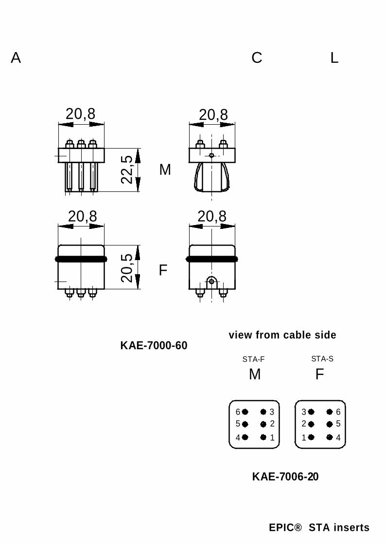
20,5
20,8
22,5
F
M
20,820,8
20,8
KAE-7000-60
M
65
4
32
1
F
32
1
65
4
STA-F STA-S
KAE-7006-20
A CL
EPIC® STA inserts
view from cable side

24
M3L1
16
A
KAE-7000-30
16 L120
,510
23
22,5
L
10
22,5
- 2
4,5
F
Mm
in.
min
.
KAE-7005-60
A CL
EPIC® STA inserts

16 L1
269
23
28
L
9
22,5
- 2
4,5
F
M
KAE-7505-6024
M3L1
16
A
KAE-7000-30
A CL
EPIC® STA inserts

FM
45678910
23
1
20191817161514131211
456789
10
23
1
20191817161514131211
KAE-7020-20
FM
4567
23
1
4567
23
1
141312111098
141312111098
KAE-7014-20
A CL
EPIC® STA inserts
view from cable side
view from cable side
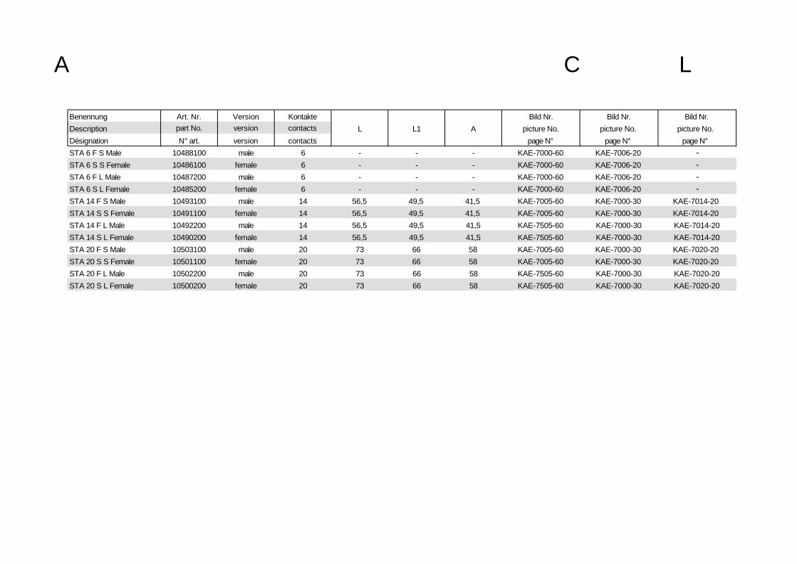
Benennung Art. Nr. Version Kontakte Bild Nr. Bild Nr. Bild Nr.Description part No. version contacts L L1 A picture No. picture No. picture No.Désignation N° art. version contacts page N° page N° page N°STA 6 F S Male 10488100 male 6 - - - KAE-7000-60 KAE-7006-20 -STA 6 S S Female 10486100 female 6 - - - KAE-7000-60 KAE-7006-20 -STA 6 F L Male 10487200 male 6 - - - KAE-7000-60 KAE-7006-20 -STA 6 S L Female 10485200 female 6 - - - KAE-7000-60 KAE-7006-20 -STA 14 F S Male 10493100 male 14 56,5 49,5 41,5 KAE-7005-60 KAE-7000-30 KAE-7014-20STA 14 S S Female 10491100 female 14 56,5 49,5 41,5 KAE-7005-60 KAE-7000-30 KAE-7014-20STA 14 F L Male 10492200 male 14 56,5 49,5 41,5 KAE-7505-60 KAE-7000-30 KAE-7014-20STA 14 S L Female 10490200 female 14 56,5 49,5 41,5 KAE-7505-60 KAE-7000-30 KAE-7014-20STA 20 F S Male 10503100 male 20 73 66 58 KAE-7005-60 KAE-7000-30 KAE-7020-20STA 20 S S Female 10501100 female 20 73 66 58 KAE-7005-60 KAE-7000-30 KAE-7020-20STA 20 F L Male 10502200 male 20 73 66 58 KAE-7505-60 KAE-7000-30 KAE-7020-20STA 20 S L Female 10500200 female 20 73 66 58 KAE-7505-60 KAE-7000-30 KAE-7020-20
A CL

27 L131
,516
34
31,2
L
16
19,5
- 21
,0
F
M
KBE-1000-60
36
M3L1
27
A
17
L
KBE-1000-30
A CL
EPIC® H-BE inserts

27 L131
,516
34
31,2
L
16
19,5
- 21
,0
F
M
KBE-1000-60
L
35
M3 L1
17
71
27
A
KBE-1100-30
A CL
EPIC® H-BE inserts

27 L1
B
B1
34
B
L
B1
M
F19,5
- 2
1,0
KBE-3000-60
36
M3L1
27
A
17
L
KBE-1000-30
A CL
EPIC® H-BE inserts
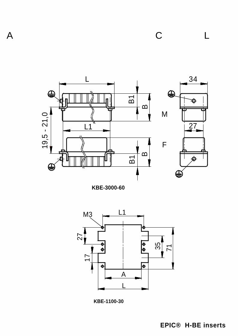
L
35
M3 L1
17
71
27
A
KBE-1100-30
27 L1
B
B1
34
B
L
B1
M
F19,5
- 2
1,0
KBE-3000-60
A CL
EPIC® H-BE inserts

36
M3L1
27
A
17
L
KBE-1000-30
27 L1
33,2
16,5
33,8
33,8
L
19,1
M
F
19,5
- 2
1,0
KBE-5000-60
A CL
EPIC® H-BE inserts

27 L1
33,2
16,5
33,8
33,8
L
19,1
M
F
19,5
- 2
1,0
KBE-5000-60
L
35
M3 L1
17
71
27
A
KBE-1100-30
A CL
EPIC® H-BE inserts

M
45
6
12
3
F
12
3
45
6
KBE-3006-20
M
678
123
F
9
10
4
5
1234
5
6789
10
KBE-3010-20
M F
87654321
109
111213141516 8
7654321
109
111213141516
KBE-3016-20
FM
87654321
109
1112
131415161718192021222324
87654321
109
1112
131415161718192021222324
KBE-3024-20
A CL
EPIC® H-BE inserts
view from cable side
view from cable side

M
87654321
109
11121314151624
23222120191817
2625
272829303132 24
23222120191817
2625
272829303132
F
87654321
109
111213141516 24
23222120191817
2625
272829303132
KBE-3032-20
F
87654321
109
1112
131415161718192021222324
M
87654321
109
1112
131415161718192021222324
3231302928272625
3433
3536
373839404142434445464748
373839404142434445464748
3231302928272625
3433
3536
KBE-3048-20
A CL
EPIC® H-BE inserts
view from cable side
view from cable side
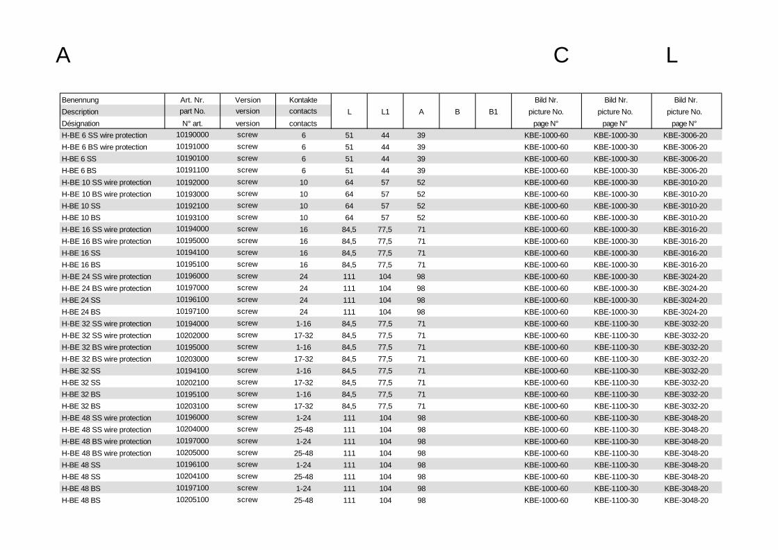
Benennung Art. Nr. Version Kontakte Bild Nr. Bild Nr. Bild Nr.Description part No. version contacts L L1 A B B1 picture No. picture No. picture No.Désignation N° art. version contacts page N° page N° page N°H-BE 6 SS wire protection 10190000 screw 6 51 44 39 KBE-1000-60 KBE-1000-30 KBE-3006-20H-BE 6 BS wire protection 10191000 screw 6 51 44 39 KBE-1000-60 KBE-1000-30 KBE-3006-20H-BE 6 SS 10190100 screw 6 51 44 39 KBE-1000-60 KBE-1000-30 KBE-3006-20H-BE 6 BS 10191100 screw 6 51 44 39 KBE-1000-60 KBE-1000-30 KBE-3006-20H-BE 10 SS wire protection 10192000 screw 10 64 57 52 KBE-1000-60 KBE-1000-30 KBE-3010-20H-BE 10 BS wire protection 10193000 screw 10 64 57 52 KBE-1000-60 KBE-1000-30 KBE-3010-20H-BE 10 SS 10192100 screw 10 64 57 52 KBE-1000-60 KBE-1000-30 KBE-3010-20H-BE 10 BS 10193100 screw 10 64 57 52 KBE-1000-60 KBE-1000-30 KBE-3010-20H-BE 16 SS wire protection 10194000 screw 16 84,5 77,5 71 KBE-1000-60 KBE-1000-30 KBE-3016-20H-BE 16 BS wire protection 10195000 screw 16 84,5 77,5 71 KBE-1000-60 KBE-1000-30 KBE-3016-20H-BE 16 SS 10194100 screw 16 84,5 77,5 71 KBE-1000-60 KBE-1000-30 KBE-3016-20H-BE 16 BS 10195100 screw 16 84,5 77,5 71 KBE-1000-60 KBE-1000-30 KBE-3016-20H-BE 24 SS wire protection 10196000 screw 24 111 104 98 KBE-1000-60 KBE-1000-30 KBE-3024-20H-BE 24 BS wire protection 10197000 screw 24 111 104 98 KBE-1000-60 KBE-1000-30 KBE-3024-20H-BE 24 SS 10196100 screw 24 111 104 98 KBE-1000-60 KBE-1000-30 KBE-3024-20H-BE 24 BS 10197100 screw 24 111 104 98 KBE-1000-60 KBE-1000-30 KBE-3024-20H-BE 32 SS wire protection 10194000 screw 1-16 84,5 77,5 71 KBE-1000-60 KBE-1100-30 KBE-3032-20H-BE 32 SS wire protection 10202000 screw 17-32 84,5 77,5 71 KBE-1000-60 KBE-1100-30 KBE-3032-20H-BE 32 BS wire protection 10195000 screw 1-16 84,5 77,5 71 KBE-1000-60 KBE-1100-30 KBE-3032-20H-BE 32 BS wire protection 10203000 screw 17-32 84,5 77,5 71 KBE-1000-60 KBE-1100-30 KBE-3032-20H-BE 32 SS 10194100 screw 1-16 84,5 77,5 71 KBE-1000-60 KBE-1100-30 KBE-3032-20H-BE 32 SS 10202100 screw 17-32 84,5 77,5 71 KBE-1000-60 KBE-1100-30 KBE-3032-20H-BE 32 BS 10195100 screw 1-16 84,5 77,5 71 KBE-1000-60 KBE-1100-30 KBE-3032-20H-BE 32 BS 10203100 screw 17-32 84,5 77,5 71 KBE-1000-60 KBE-1100-30 KBE-3032-20H-BE 48 SS wire protection 10196000 screw 1-24 111 104 98 KBE-1000-60 KBE-1100-30 KBE-3048-20H-BE 48 SS wire protection 10204000 screw 25-48 111 104 98 KBE-1000-60 KBE-1100-30 KBE-3048-20H-BE 48 BS wire protection 10197000 screw 1-24 111 104 98 KBE-1000-60 KBE-1100-30 KBE-3048-20H-BE 48 BS wire protection 10205000 screw 25-48 111 104 98 KBE-1000-60 KBE-1100-30 KBE-3048-20H-BE 48 SS 10196100 screw 1-24 111 104 98 KBE-1000-60 KBE-1100-30 KBE-3048-20H-BE 48 SS 10204100 screw 25-48 111 104 98 KBE-1000-60 KBE-1100-30 KBE-3048-20H-BE 48 BS 10197100 screw 1-24 111 104 98 KBE-1000-60 KBE-1100-30 KBE-3048-20H-BE 48 BS 10205100 screw 25-48 111 104 98 KBE-1000-60 KBE-1100-30 KBE-3048-20
A CL

Benennung Art. Nr. Version Kontakte Bild Nr. Bild Nr. Bild Nr.Description part No. version contacts L L1 A B B1 picture No. picture No. picture No.Désignation N° art. version contacts page N° page N° page N°H-BE 6 SCM 10180000 crimp 6 51 44 39 33 18 KBE-3000-60 KBE-1000-30 KBE-3006-20H-BE 6 BCM 10181000 crimp 6 51 44 39 34 18 KBE-3000-60 KBE-1000-30 KBE-3006-20H-BE 10 SCM 10182000 crimp 10 64 57 52 33 18 KBE-3000-60 KBE-1000-30 KBE-3010-20H-BE 10 BCM 10183000 crimp 10 64 57 52 34 18 KBE-3000-60 KBE-1000-30 KBE-3010-20H-BE 16 SCM 10184000 crimp 16 84,5 77,5 71 33 18 KBE-3000-60 KBE-1000-30 KBE-3016-20H-BE 16 BCM 10185000 crimp 16 84,5 77,5 71 34 18 KBE-3000-60 KBE-1000-30 KBE-3016-20
H-BE 24 SCM 10186000 crimp 24 111 104 98 33 18 KBE-3000-60 KBE-1000-30 KBE-3024-20
H-BE 24 BCM 10187000 crimp 24 111 104 98 34 18 KBE-3000-60 KBE-1000-30 KBE-3024-20H-BE 16 SCM 10184000 crimp 1-16 84,5 77,5 71 33 18 KBE-3000-60 KBE-1100-30 KBE-3032-20H-BE 16 SCM 10184200 crimp 17-32 84,5 77,5 71 34 18 KBE-3000-60 KBE-1100-30 KBE-3032-20H-BE 16 BCM 10185000 crimp 1-16 84,5 77,5 71 33 18 KBE-3000-60 KBE-1100-30 KBE-3032-20H-BE 16 BCM 10185200 crimp 17-32 84,5 77,5 71 34 18 KBE-3000-60 KBE-1100-30 KBE-3032-20H-BE 24 SCM 10186000 crimp 1-24 111 104 98 33 18 KBE-3000-60 KBE-1100-30 KBE-3048-20H-BE 24 SCM 10186200 crimp 25-48 111 104 98 34 18 KBE-3000-60 KBE-1100-30 KBE-3048-20H-BE 24 BCM 10187000 crimp 1-24 111 104 98 33 18 KBE-3000-60 KBE-1100-30 KBE-3048-20H-BE 24 BCM 10187200 crimp 25-48 111 104 98 34 18 KBE-3000-60 KBE-1100-30 KBE-3048-20H-BE 6 SF 10400000 Cage clamp 6 49,8 44 39 KBE-5000-60 KBE-1000-30 KBE-3006-20H-BE 6 BF 10401000 Cage clamp 6 49,8 44 39 KBE-5000-60 KBE-1000-30 KBE-3006-20H-BE 10 SF 10400100 Cage clamp 10 62,8 57 52 KBE-5000-60 KBE-1000-30 KBE-3010-20H-BE 10 BF 10401100 Cage clamp 10 62,8 57 52 KBE-5000-60 KBE-1000-30 KBE-3010-20H-BE 16 SF 10400200 Cage clamp 16 83,3 77,5 71 KBE-5000-60 KBE-1000-30 KBE-3016-20H-BE 16 BF 10401200 Cage clamp 16 83,3 77,5 71 KBE-5000-60 KBE-1000-30 KBE-3016-20H-BE 24 SF 10400300 Cage clamp 24 109,8 104 98 KBE-5000-60 KBE-1000-30 KBE-3024-20H-BE 24 BF 10401300 Cage clamp 24 109,8 104 98 KBE-5000-60 KBE-1000-30 KBE-3024-20H-BE 16 SF 1 - 16 10400200 Cage clamp 1-16 83,3 77,5 71 KBE-5000-60 KBE-1100-30 KBE-3032-20H-BE 16 SF 17-32 10400400 Cage clamp 17-32 83,3 77,5 71 KBE-5000-60 KBE-1100-30 KBE-3032-20H-BE 16 BF 1-16 10401200 Cage clamp 1-16 83,3 77,5 71 KBE-5000-60 KBE-1100-30 KBE-3032-20H-BE 16 BF 17-32 10401400 Cage clamp 17-32 83,3 77,5 71 KBE-5000-60 KBE-1100-30 KBE-3032-20H-BE 24 SF 1-16 10400300 Cage clamp 1-24 109,8 104 98 KBE-5000-60 KBE-1100-30 KBE-3048-20H-BE 24 SF 25-48 10400500 Cage clamp 25-48 109,8 104 98 KBE-5000-60 KBE-1100-30 KBE-3048-20H-BE 24 BF 1-16 10401300 Cage clamp 1-24 109,8 104 98 KBE-5000-60 KBE-1100-30 KBE-3048-20H-BE 24 BF 25-48 10401500 Cage clamp 25-48 109,8 104 98 KBE-5000-60 KBE-1100-30 KBE-3048-20
A CL

27 L1
35,5
16,5
34
34
L 19
19,5
- 2
1,0
F
M
KBE-1000-65
36M3
L1
27
A
17
L
KBE-1000-30
A CL
EPIC® H-BS inserts

27 L1
35,5
16,5
34
34
L 19
19,5
- 2
1,0
F
M
KBE-1000-65
L
35
M3 L1
17
71
27
A
KBE-1100-30
A CL
EPIC® H-BS inserts

M F
5
3
12
4
65
3
12
4
6
KBE-3006-25
M F
5
3
12
4
65
3
12
4
69
8
710
11
12
10
11
129
8
7
KBE-3012-25
A CL
EPIC® H-BS inserts
view from cable side
view from cable side

Benennung Art. Nr. Version Kontakte Bild Nr. Bild Nr. Bild Nr.Description part No. version contacts L L1 A picture No. picture No. picture No.Désignation N° art. version contacts page N° page N° page N°H-BS 6 S wire protection 10170000 screw 6 84,5 77,5 71 KBE-1000-65 KBE-3006-25 KBE-1000-30H-BS 6 B wire protection 10171000 screw 6 84,5 77,5 71 KBE-1000-65 KBE-3006-25 KBE-1000-30H-BS 12 S wire protection 10170000 screw 1-6 84,5 77,5 71 KBE-1000-65 KBE-3012-25 KBE-1100-30H-BS 12 S wire protection 10170600 screw 7-12 84,5 77,5 71 KBE-1000-65 KBE-3012-25 KBE-1100-30H-BS 12 B wire protection 10171000 screw 1-6 84,5 77,5 71 KBE-1000-65 KBE-3012-25 KBE-1100-30H-BS 12 B wire protection 10171600 screw 7-12 84,5 77,5 71 KBE-1000-65 KBE-3012-25 KBE-1100-30
A CL

27 L131
,516
34
31,2
L
16
19,5
- 21
,0
F
M
KBE-1000-60
36
M3L1
27
A
17
L
KBE-1000-30
A CL
EPIC® H-BVE inserts

M
71
3
F
95
1
3
5
7
9
Schaltkontaktmating con tact
contact de branchemen t
Arbeitskontaktworking contact
contact de travail
KBE-1003-20
M F
7
5
3
110
12
14
167
5
3
110
12
14
16
KBE-1006-20
F
7
5
3
1
9
11
14
16
18
20
22
24
M
7
5
3
1
9
11
14
16
18
20
22
24
KBE-1010-20
A CL
EPIC® H-BVE inserts
view from cable side
view from cable side

Benennung Art. Nr. Version Kontakte Bild Nr. Bild Nr. Bild Nr.Description part No. version contacts L L1 A picture No. picture No. picture No.Désignation N° art. version contacts page N° page N° page N°H-BVE 3 SS wire protection 10210010 male 3 64 57 52 KBE-1000-60 KBE-1003-20 KBE-1000-30H-BVE 3 BS wire protection 10211010 female 3 64 57 52 KBE-1000-60 KBE-1003-20 KBE-1000-30H-BVE 3 SS 10210110 male 3 64 57 52 KBE-1000-60 KBE-1003-20 KBE-1000-30H-BVE 3 BS 10211110 female 3 64 57 52 KBE-1000-60 KBE-1003-20 KBE-1000-30H-BVE 6 SS wire protection 10239010 male 6 84,5 77,5 71 KBE-1000-60 KBE-1006-20 KBE-1000-30H-BVE 6 BS wire protection 10240010 female 6 84,5 77,5 71 KBE-1000-60 KBE-1006-20 KBE-1000-30H-BVE 6 SS 10239110 male 6 84,5 77,5 71 KBE-1000-60 KBE-1006-20 KBE-1000-30H-BVE 6 BS 10240110 female 6 84,5 77,5 71 KBE-1000-60 KBE-1006-20 KBE-1000-30H-BVE 10 SS wire protection 10270010 male 10 111 104 98 KBE-1000-60 KBE-1010-20 KBE-1000-30H-BVE 10 BS wire protection 10271010 female 10 111 104 98 KBE-1000-60 KBE-1010-20 KBE-1000-30H-BVE 10 SS 10270110 male 10 111 104 98 KBE-1000-60 KBE-1010-20 KBE-1000-30H-BVE 10 BS 10271110 female 10 111 104 98 KBE-1000-60 KBE-1010-20 KBE-1000-30
A CL

A CL
EPIC® H-D inserts
view from cable side

24
M3L1
16
A
10
L
KAE-1000-30
A CL
EPIC® H-D inserts

A CL
EPIC® H-D inserts
view from cable side
view from cable side

A CL
EPIC® H-D inserts
view from cable side

27 L1
B
B1
34
B
L
B1
M
F19,5
- 21
,0
KBE-3000-6036
M3L1
27
A
17
L
KBE-1000-30
A CL
EPIC® H-D inserts

A CL
EPIC® H-D inserts
view from cable side

27 L1
B
B1
34
B
L
B1
M
F19,5
- 21
,0
KBE-3000-60
L
35
M3 L1
17
71
27
A
KBE-1100-30
A CL
EPIC® H-D inserts

A CL
EPIC® H-D inserts
view from cable side

Benennung Art. Nr. Version Kontakte Bild Nr. Bild Nr. Bild Nr.Description part No. version contacts L L1 A / H B B1 picture No. picture No. picture No.
Désignation N° art. version contacts page N° page N° page N°H-D 7 SCM 11250500 male 7 21 23,6 34 KDE-3000-60 KDE-3007-20H-D 7 BCM 11251500 female 7 21 17 33,2 KDE-3000-60 KDE-3007-20H-D 7 SCG 11250000 male 7 21 23,6 33,6 KDE-3000-60 KDE-3007-20H-D 7 BCG 11251000 female 7 21 17 32,2 KDE-3000-60 KDE-3007-20H-D 8 SCM 11252500 male 8 21 23,6 34 KDE-3000-60 KDE-3008-20H-D 8 BCM 11253500 female 8 21 17 33,2 KDE-3000-60 KDE-3008-20H-D 15 SCM 11255100 male 15 56,5 49,5 42,5 KDE-3100-60 KAE-1000-30 KDE-3015-20H-D 15 BCM 11256100 female 15 56,5 49,5 42,5 KDE-3100-60 KAE-1000-30 KDE-3015-20H-D 15 SCG 11255000 male 15 56,5 49,5 42,5 KDE-3100-60 KAE-1000-30 KDE-3015-20H-D 15 BCG 11256000 female 15 56,5 49,5 42,5 KDE-3100-60 KAE-1000-30 KDE-3015-20H-D 25 SCM 11260200 male 25 73 66 60 KDE-3100-60 KAE-1000-30 KDE-3025-20H-D 25 BCM 11261200 female 25 73 66 60 KDE-3100-60 KAE-1000-30 KDE-3025-20H-D 25 SCG 11260000 male 25 73 66 60 KDE-3100-60 KAE-1000-30 KDE-3025-20H-D 25 BCG 11261000 female 25 73 66 60 KDE-3100-60 KAE-1000-30 KDE-3025-20H-D 50 SCM 11260200 male 2 x 25 73 66 60 KDE-3100-60 KAE-1100-30 KDE-3050-20H-D 50 BCM 11261200 female 2 x 25 73 66 60 KDE-3100-60 KAE-1100-30 KDE-3050-20H-D 50 SCG 11260000 male 2 x 25 73 66 60 KDE-3100-60 KAE-1100-30 KDE-3050-20H-D 50 BCG 11261000 female 2 x 25 73 66 60 KDE-3100-60 KAE-1100-30 KDE-3050-20H-D 40 SCM 11265200 male 40 84,5 77,5 71 39,3 24 KBE-3000-60 KBE-1000-30 KDE-3040-20H-D 40 BCM 11266200 female 40 84,5 77,5 71 34,6 16 KBE-3000-60 KBE-1000-30 KDE-3040-20H-D 40 SCG 11265000 male 40 84,5 77,5 71 34 19 KBE-3000-60 KBE-1000-30 KDE-3040-20H-D 40 BCG 11266000 female 40 84,5 77,5 71 36 18 KBE-3000-60 KBE-1000-30 KDE-3040-20H-D 64 SCM 11272000 male 64 111 104 98 39,3 24 KBE-3000-60 KBE-1000-30 KDE-3064-20H-D 64 BCM 11273000 female 64 111 104 98 34,6 16 KBE-3000-60 KBE-1000-30 KDE-3064-20H-D 64 SCG 11270000 male 64 111 104 98 34 19 KBE-3000-60 KBE-1000-30 KDE-3064-20H-D 64 BCG 11271000 female 64 111 104 98 36 18 KBE-3000-60 KBE-1000-30 KDE-3064-20
A CL

Benennung Art. Nr. Version Kontakte Bild Nr. Bild Nr. Bild Nr.Description part No. version contacts L L1 A / H B B1 picture No. picture No. picture No.
Désignation N° art. version contacts page N° page N° page N°H-D 80 SCM 11265200 male 2 x 40=80 84,5 77,5 71 39,3 24 KBE-3000-60 KBE-1100-30 KDE-3080-20H-D 80 BCM 11266200 female 2 x 40=80 84,5 77,5 71 34,6 16 KBE-3000-60 KBE-1100-30 KDE-3080-20H-D 80 SCG 11265000 male 2 x 40=80 84,5 77,5 71 34 19 KBE-3000-60 KBE-1100-30 KDE-3080-20H-D 80 BCG 11266000 female 2 x 40=80 84,5 77,5 71 36 18 KBE-3000-60 KBE-1100-30 KDE-3080-20H-D 128 SCM 11272000 male 2 x 64=128 111 104 98 39,3 24 KBE-3000-60 KBE-1100-30 KDE-3128-20H-D 128 BCM 11273000 female 2 x 64=128 111 104 98 34,6 16 KBE-3000-60 KBE-1100-30 KDE-3128-20H-D 128 SCG 11270000 male 2 x 64=128 111 104 98 34 19 KBE-3000-60 KBE-1100-30 KDE-3128-20H-D 128 BCG 11271000 female 2 x 64=128 111 104 98 36 18 KBE-3000-60 KBE-1100-30 KDE-3128-20
A CL

36
M3L1
27
A
17
L
KBE-1000-30
A CL
EPIC® H-DD inserts

A CL
EPIC® H-DD inserts
view from cable side
view from cable side
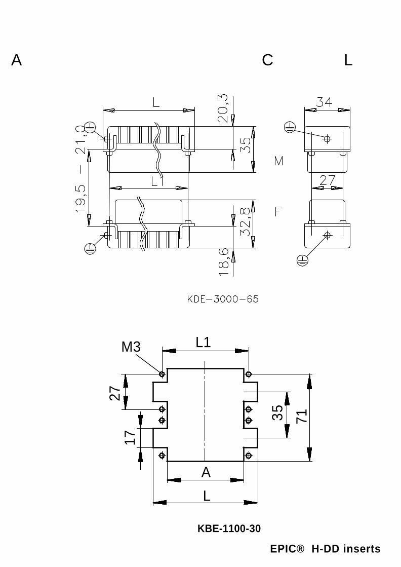
L
35
M3 L1
17
71
27
A
KBE-1100-30
A CL
EPIC® H-DD inserts

A CL
EPIC® H-DD inserts
view from cable side
view from cable side

A CL
EPIC® H-DD inserts
view from cable side

Benennung Art. Nr. Version Kontakte Bild Nr. Bild Nr. Bild Nr.Description part No. version contacts L L1 A picture No. picture No. picture No.
Désignation N° art. version contacts page N° page N° page N°H-DD 24 SCM 11285000 male 24 50,5 44 36 KDE-3000-65 KDE-3024-25 KBE-1000-30H-DD 24 BCM 11286000 female 24 50,5 44 36 KDE-3000-65 KDE-3024-25 KBE-1000-30H-DD 42 SCM 11285100 male 42 63,5 57 49 KDE-3000-65 KDE-3042-25 KBE-1000-30H-DD 42 BCM 11286100 female 42 63,5 57 49 KDE-3000-65 KDE-3042-25 KBE-1000-30H-DD 72 SCM 11285200 male 72 84 77,5 69,5 KDE-3000-65 KDE-3072-25 KBE-1000-30H-DD 72 BCM 11286200 female 72 84 77,5 69,5 KDE-3000-65 KDE-3072-25 KBE-1000-30H-DD 108 SCM 1-108 11285300 male 108 110,5 104 96 KDE-3000-65 KDE-3108-25 KBE-1000-30H-DD 108 BCM 1-108 11286300 female 108 110,5 104 96 KDE-3000-65 KDE-3108-25 KBE-1000-30H-DD 72 SCM 1-72 11285200 male 1 - 72 84 77,5 69,5 KDE-3000-65 KDE-3144-25 KBE-1100-30H-DD 72 SCM 73-144 11285400 male 73 - 144 84 77,5 69,5 KDE-3000-65 KDE-3144-25 KBE-1100-30H-DD 72 BCM 1-72 11286200 female 1 - 72 84 77,5 69,5 KDE-3000-65 KDE-3144-25 KBE-1100-30H-DD 72 BCM 73-144 11286400 female 73 - 144 84 77,5 69,5 KDE-3000-65 KDE-3144-25 KBE-1100-30H-DD 108 SCM 1-108 11285300 male 1 - 108 110,5 104 96 KDE-3000-65 KDE-3216-25 KBE-1100-30H-DD 108 SCM 109-216 11285500 male 109 - 216 110,5 104 96 KDE-3000-65 KDE-3216-25 KBE-1100-30H-DD 108 BCM 1-108 11286300 female 1 - 108 110,5 104 96 KDE-3000-65 KDE-3216-25 KBE-1100-30H-DD 108 BCM 109-216 11286500 female 109 - 216 110,5 104 96 KDE-3000-65 KDE-3216-25 KBE-1100-30
A CL

M
F
KBE-4003-21
M
F
PE
PE
KBE-4005-25
M
F
1
2
3
4
3 1
24
KBE-4004-20
F
M
KBE-4000-20
M
F
1233
2 1
KBE-4003-20
M
F
24
5 3 1
24
5 3 1
KBE-4005-20
A CL
EPIC® MC series
view from cable side
view from cable side

M
F
11
6610
510
5
KBE-4010-20
M
F
11
14
1420
720
7
13 8
813
KBE-4020-20
KBE-4020-21
A CL
EPIC® MC series
view from cable side
view from cable side

35
L1L
1927 34
...
... AA
35
AA
L1L
16,5
27 34
...
...
M F
KBE-4000-60
36
M3L1
27
A
17
L
KBE-1000-30
A CL
EPIC® MC series

Benennung Art. Nr. Version Kontakte Bild Nr. Bild Nr.Description part No. version contacts L L1 H picture No. picture No.
Désignation N° art. version contacts page N° page N°MCS 3 Koax 10399200 male 3 KBE-4003-21MCB 3 Koax 10399300 female 3 KBE-4003-21MCS 5CG 10383200 male 4+PE KBE-4005-25MCB 5 CG 10383300 female 4+PE KBE-4005-25MCS 4 CM 10399000 male 4 KBE-4004-20MCB 4 CM 10399100 female 4 KBE-4004-20MCS 0 Blind 10399400 male 0 KBE-4000-20MCB 0 Blind 10399500 female 0 KBE-4000-20MCS 3 CM 10382000 male 3 KBE-4003-20MCB 3 CM 10382100 female 3 KBE-4003-20MCS 5 CM 10382200 male 5 KBE-4005-20MCB 5 CM 10382300 female 5 KBE-4005-20MCS 10 CM 10382400 male 10 KBE-4010-20MCB 10 CM 10382500 female 10 KBE-4010-20MCS 10 CG 10383400 male 10 KBE-4010-20MCB 10 CG 10383500 female 10 KBE-4010-20MCS 20 CM 10383600 male 20 KBE-4020-20MCB 20 CM 10383700 female 20 KBE-4020-20MCS 4 F 10399600 male 4 KBE-4003-22MCB 4 F 10399700 female 4 KBE-4003-22MCS 3 CM-HV 10399800 male 3 KBE-4020-21MCB 3 CM-HV 10399900 female 3 KBE-4020-21MCR 6 10381000 male 0-40 51 44 KBE-4000-60 KBE-1000-30MCR 6 10381100 female 0-40 51 44 KBE-4000-60 KBE-1000-30MCR 10 10381200 male 0-60 64 57 KBE-4000-60 KBE-1000-30MCR 10 10381300 female 0-60 64 57 KBE-4000-60 KBE-1000-30MCR 16 10381400 male 0-100 84,5 77,5 KBE-4000-60 KBE-1000-30MCR 16 10381500 female 0-100 84,5 77,5 KBE-4000-60 KBE-1000-30MCR 24 10381600 male 0-140 111 104 KBE-4000-60 KBE-1000-30MCR 24 10381700 female 0-140 111 104 KBE-4000-60 KBE-1000-30MCR 16+16 2x 10381400 male 0-200 84,5 77,5 KBE-4000-60 KBE-1100-30MCR 16+16 2x 10381500 female 0-200 84,5 77,5 KBE-4000-60 KBE-1100-30MCR 24+24 2x 10381600 male 0-280 111 104 KBE-4000-60 KBE-1100-30MCR 24+24 2x 10381700 female 0-280 111 104 KBE-4000-60 KBE-1100-30
A CL

27 33
82L L1
L2
83
M F
PE links / left / à gauche PE rechts / ri ght / à droite
KBE-6000-60
A CL
EPIC® TB-H-BE

F
456
123
M
123
456
KBE-6006-20
F
678
123
M
9
10
4
5
1234
5
6789
10
KBE-6010-20
M F
87654321
109
1112131415168
7654321
109
111213141516
KBE-6016-20
M F
87654321
109
1112
131415161718192021222324
87654321
109
1112
131415161718192021222324
KBE-6024-20
A CL
EPIC® TB-H-BE
view from cable side
view from cable side

Benennung Art. Nr. Version Version Kontakte Bild Nr. Bild Nr.Description part No. version version contacts L L1 L2 picture No. picture No.
Désignation N° art. version version contacts page N° page N°TB-H-BE 6 SRE 70300000 male right 6 49,8 44 KBE-6000-60 KBE-6006-20TB-H-BE 6 BRE 70301100 female right 6 49,8 44 KBE-6000-60 KBE-6006-20TB-H-BE 6 SLI 70301000 male left 6 49,8 44 KBE-6000-60 KBE-6006-20TB-H-BE 6 BLI 70300100 female left 6 49,8 44 KBE-6000-60 KBE-6006-20TB-H-BE 6 SRE-RA 70300500 male right 6 49,8 44 60 KBE-6000-60 KBE-6006-20TB-H-BE 6 BRE-RA 70301600 female right 6 49,8 44 60 KBE-6000-60 KBE-6006-20TB-H-BE 6 SLI-RA 70301500 male left 6 49,8 44 60 KBE-6000-60 KBE-6006-20TB-H-BE 6 BLI-RA 70300600 female left 6 49,8 44 60 KBE-6000-60 KBE-6006-20TB-H-BE 10 SRE 70302000 male right 10 63,2 57 KBE-6000-60 KBE-6010-20TB-H-BE 10 BRE 70303100 female right 10 63,2 57 KBE-6000-60 KBE-6010-20TB-H-BE 10 SLI 70303000 male left 10 63,2 57 KBE-6000-60 KBE-6010-20TB-H-BE 10 BLI 70302100 female left 10 63,2 57 KBE-6000-60 KBE-6010-20TB-H-BE 10 SRE-RA 70302500 male right 10 63,2 57 73 KBE-6000-60 KBE-6010-20TB-H-BE 10 BRE-RA 70303600 female right 10 63,2 57 73 KBE-6000-60 KBE-6010-20TB-H-BE 10 SLI-RA 70303500 male left 10 63,2 57 73 KBE-6000-60 KBE-6010-20TB-H-BE 10 BLI-RA 70302600 female left 10 63,2 57 73 KBE-6000-60 KBE-6010-20TB-H-BE 16 SRE 70304000 male right 16 83,3 77,5 KBE-6000-60 KBE-6016-20TB-H-BE 16 BRE 70305100 female right 16 83,3 77,5 KBE-6000-60 KBE-6016-20TB-H-BE 16 SLI 70305000 male left 16 83,3 77,5 KBE-6000-60 KBE-6016-20TB-H-BE 16 BLI 70304100 female left 16 83,3 77,5 KBE-6000-60 KBE-6016-20TB-H-BE 16 SRE-RA 70304500 male right 16 83,3 77,5 83 KBE-6000-60 KBE-6016-20TB-H-BE 16 BRE-RA 70305600 female right 16 83,3 77,5 83 KBE-6000-60 KBE-6016-20TB-H-BE 16 SLI-RA 70305500 male left 16 83,3 77,5 83 KBE-6000-60 KBE-6016-20TB-H-BE 16 BLI-RA 70304600 female left 16 83,3 77,5 83 KBE-6000-60 KBE-6016-20TB-H-BE 24 SRE 70306000 male right 24 110,1 104 KBE-6000-60 KBE-6024-20TB-H-BE 24 BRE 70307100 female right 24 110,1 104 KBE-6000-60 KBE-6024-20TB-H-BE 24 SLI 70307000 male left 24 110,1 104 KBE-6000-60 KBE-6024-20TB-H-BE 24 BLI 70306100 female left 24 110,1 104 KBE-6000-60 KBE-6024-20TB-H-BE 24 SRE-RA 70306500 male right 24 110,1 104 120 KBE-6000-60 KBE-6024-20TB-H-BE 24 BRE-RA 70307600 female right 24 110,1 104 120 KBE-6000-60 KBE-6024-20TB-H-BE 24 SLI-RA 70307500 male left 24 110,1 104 120 KBE-6000-60 KBE-6024-20TB-H-BE 24 BLI-RA 70306600 female left 24 110,1 104 120 KBE-6000-60 KBE-6024-20
A CL

27 33
82L L1
L283
M F
PE links / left / à gauche PE rechts / right / à droite
KBE-6000-60
A CL
EPIC® TB-H-D

A CL
EPIC® TB-H-D
view from cable side
view from cable side

A CL
EPIC® TB-H-D
view from cable side

Benennung Art. Nr. Version Version Kontakte Bild Nr. Bild Nr.Description part No. version version contacts L L1 L2 picture No. picture No.
Désignation N° art. version version contacts page N° page N°TB-H-D 16 SRE 71300000 male right 16 49,8 44 KDE-6000-60 KDE-6016-20TB-H-D 16 BRE 71301100 female right 16 49,8 44 KDE-6000-60 KDE-6016-20TB-H-D 16 SLI 71301000 male left 16 49,8 44 KDE-6000-60 KDE-6016-20TB-H-D 16 BLI 71300100 female left 16 49,8 44 KDE-6000-60 KDE-6016-20TB-H-D 16 SRE-RA 71300500 male right 16 49,8 44 58,6 KDE-6000-60 KDE-6016-20TB-H-D 16 BRE-RA 71301600 female right 16 49,8 44 58,6 KDE-6000-60 KDE-6016-20TB-H-D 16 SLI-RA 71301500 male left 16 49,8 44 58,6 KDE-6000-60 KDE-6016-20TB-H-D 16 BLI-RA 71300600 female left 16 49,8 44 58,6 KDE-6000-60 KDE-6016-20TB-H-D 24 SRE 71302000 male right 24 63,2 57 KDE-6000-60 KDE-6024-20TB-H-D 24 BRE 71303100 female right 24 63,2 57 KDE-6000-60 KDE-6024-20TB-H-D 24 SLI 71303000 male left 24 63,2 57 KDE-6000-60 KDE-6024-20TB-H-D 24 BLI 71302100 female left 24 63,2 57 KDE-6000-60 KDE-6024-20TB-H-D 24 SRE-RA 71302500 male right 24 63,2 57 72 KDE-6000-60 KDE-6024-20TB-H-D 24 BRE-RA 71303600 female right 24 63,2 57 72 KDE-6000-60 KDE-6024-20TB-H-D 24 SLI-RA 71303500 male left 24 63,2 57 72 KDE-6000-60 KDE-6024-20TB-H-D 24 BLI-RA 71302600 female left 24 63,2 57 72 KDE-6000-60 KDE-6024-20TB-H-D 40 SRE 71304000 male right 40 83,3 77,5 KDE-6000-60 KDE-6040-20TB-H-D 40 BRE 71305100 female right 40 83,3 77,5 KDE-6000-60 KDE-6040-20TB-H-D 40 SLI 71305000 male left 40 83,3 77,5 KDE-6000-60 KDE-6040-20TB-H-D 40 BLI 71304100 female left 40 83,3 77,5 KDE-6000-60 KDE-6040-20TB-H-D 40 SRE-RA 71304500 male right 40 83,3 77,5 92,2 KDE-6000-60 KDE-6040-20TB-H-D 40 BRE-RA 71305600 female right 40 83,3 77,5 92,2 KDE-6000-60 KDE-6040-20TB-H-D 40 SLI-RA 71305500 male left 40 83,3 77,5 92,2 KDE-6000-60 KDE-6040-20TB-H-D 40 BLI-RA 71304600 female left 40 83,3 77,5 92,2 KDE-6000-60 KDE-6040-20TB-H-D 64-SRE 71306000 male right 64 110,1 104 KDE-6000-60 KDE-6064-20TB-H-D 64 BRE 71307100 female right 64 110,1 104 KDE-6000-60 KDE-6064-20TB-H-D 64 SLI 71307000 male left 64 110,1 104 KDE-6000-60 KDE-6064-20TB-H-D 64 BLI 71306100 female left 64 110,1 104 KDE-6000-60 KDE-6064-20TB-H-D 64-SRE-RA 71306500 male right 64 110,1 104 119 KDE-6000-60 KDE-6064-20TB-H-D 64 BRE-RA 71307600 female right 64 110,1 104 119 KDE-6000-60 KDE-6064-20TB-H-D 64 SLI-RA 71307500 male left 64 110,1 104 119 KDE-6000-60 KDE-6064-20TB-H-D 64 BLI-RA 71306600 female left 64 110,1 104 119 KDE-6000-60 KDE-6064-20
A CL

26,8
LogoFa.-
B
50HTgv without or with Pg 11
KAG-0015-00
26,8
KAG-0015-00 + KAG-0025-00
B
25
48
LogoFa.-
36
HTgv without or with Pg 11
A CL
EPIC® H-A housings

KAG-0205-00
36,5
23,8 34,5
28
22
3,3 30
2,5
40
28
36,5
23,8
3040
40,5
3,3
25,8
34,53,5
KAG-0206-00
A CL
EPIC® H-A housings

KAG-0105-00
Fa.-Logo H53,5
34,536,526,8
Tgvb without or with Pg 11
23,8
KAG-0165-00
28
36,5
23,834,5
40,5
3040
3,3
25,8
H
3,5
Agsv without Pg 11
Agsv with Pg 11or
A CL
EPIC® H-A housings

Benennung Art. Nr. Version Version Version Version PG size Bild Nr.Description part No. version version version version PG Größe B H picture No.
Désignation N° art. version version version version PG page N°H-A 3 MTgv 10512100 without PG top metal black 11 33,5 KAG-0015-00H-A 3 Tgv 10425500 without PG top plastic black 11 36 KAG-0015-00H-A 3 Tgv 10426000 without PG top plastic grey 11 36 KAG-0015-00H-A 3 MTgv 10620600 with PG top metal black 11 33,5 57 KAG-0015-00H-A 3 Tgv 10427100 with PG top plastic black 11 36 62 KAG-0015-00H-A 3 Tgv 10512900 with PG top plastic grey 11 36 62 KAG-0015-00H-A 3 MTs 10512300 without PG side metal black 11 33,5 KAG-0025-00H-A 3 Ts 10427300 without PG side plastic black 11 36 KAG-0025-00H-A 3 Ts 10427000 without PG side plastic grey 11 36 KAG-0025-00H-A 3 MTs 10427500 with PG side metal black 11 33,5 43 KAG-0025-00H-A 3 Ts 10620600 with PG side plastic black 11 36 48 KAG-0025-00H-A 3 Ts 10427100 with PG side plastic grey 11 36 48 KAG-0025-00H-A 3 MAg 10422500 metal black KAG-0205-00H-A 3 Ag 10422200 plastic black KAG-0205-00H-A 3 Ag 10422000 plastic grey KAG-0205-00H-A 3 MAg 10423500 metal black KAG-0206-00H-A 3 Ag 10423100 plastic black KAG-0206-00H-A 3 Ag 10423000 plastic grey KAG-0206-00H-A 3 MAgsv 10512700 without PG metal black 51,5 KAG-0105-00H-A 3 Agsv 10511700 without PG plastic black 56 KAG-0105-00H-A 3 Agsv 10424000 without PG plastic grey 56 KAG-0105-00H-A 3 MAgsv 10424500 with PG metal black 57,5 KAG-0105-00H-A 3 Agsv 10424700 with PG plastic black 65 KAG-0105-00H-A 3 Agsv 10424200 with PG plastic grey 65 KAG-0105-00H-A 3 MTgvb 10512900 without PG top metal black 11 KAG-0165-00H-A 3 Tgvb 10429200 without PG top plastic black 11 KAG-0165-00H-A 3 Tgvb 10429000 without PG top plastic grey 11 KAG-0165-00H-A 3 MTgvb 10429500 with PG top metal black 11 60 KAG-0165-00H-A 3 Tgvb 10620300 with PG top plastic black 11 65 KAG-0165-00H-A 3 Tgvb 10429100 with PG top plastic grey 11 65 KAG-0165-00
A CL
A CL

B
H Pg
KAG-0020-00
3°
27.10.1997
SuchyTüllengehäuse
LL1
TsTgPg
LogoFa.-
01 - - - - - - - - --
A CL
EPIC® H-A housings

Benennung Art. Nr. Art. Nr. Kabel Eingang
Description part No. part No. Cable entry PG L L1 B HDésignation N° art. N° art. sortie
H-A 10 TS 16 ZW. 10445000 seitlich, side, latérale 16 63 73 29,5 53,3H-A 10 TS-K 16 ZW. 70463000 seitlich, side, latérale 16 63 73 29,5 53,3H-A 10 TG 16 ZW. 10446100 gerade, top, verticale 16 63 73 29,5 53,3H-A 10 TG-K 16 ZW. 70461000 gerade, top, verticale 16 63 73 29,5 53,3H-A 16 TS 16 ZW. 10564000 seitlich, side, latérale 16 79 89 29,5 58,3H-A 16 TS-K 16 ZW. 70493000 seitlich, side, latérale 16 79 89 29,5 58,3H-A 16 TG 16 ZW. 10565000 gerade, top, verticale 16 79 89 29,5 58,3H-A 16 TG-K 16 ZW. 70491000 gerade, top, verticale 16 79 89 29,5 58,3H-A 10 TSH 16 70462200 seitlich, side, latérale 16 63 73 29,5 67,3H-A 10 TS 16 ZW. 10445000 seitlich, side, latérale 16 63 73 29,5 53,3H-A 10 TS-K 16 ZW. 70463000 seitlich, side, latérale 16 63 73 29,5 53,3H-A 10 TG 16 ZW. 10446100 gerade, top, verticale 16 63 73 29,5 53,3H-A 10 TG-K 16 ZW. 70461000 gerade, top, verticale 16 63 73 29,5 53,3H-A 10 TSH 21 70462400 seitlich, side, latérale 21 63 73 29,5 67,3H-A 10 TSH-K 16 70463200 seitlich, side, latérale 16 63 73 29,5 67,3H-A 10 TSH-K 21 70463400 seitlich, side, latérale 21 63 73 29,5 67,3H-A 10 TGH 16 70460200 gerade, top, verticale 16 63 73 29,5 67,3H-A 10 TGH 21 70460400 gerade, top, verticale 21 63 73 29,5 67,3H-A 10 TGH-K 16 70461200 gerade, top, verticale 16 63 73 29,5 67,3H-A 10 TGH-K 21 70461400 gerade, top, verticale 21 63 73 29,5 67,3H-A 16 TS 16 ZW. 10564000 seitlich, side, latérale 16 79 89 29,5 58,3H-A 16 TS-K 16 ZW. 70493000 seitlich, side, latérale 16 79 89 29,5 58,3H-A 16 TG 16 ZW. 10565000 gerade, top, verticale 16 79 89 29,5 58,3H-A 16 TG-K 16 ZW. 70491000 gerade, top, verticale 16 79 89 29,5 58,3H-A 16 TSH 16 ZW. 70492200 seitlich, side, latérale 16 79 89 29,5 72,3H-A 16 TSH 21 ZW. 70492400 seitlich, side, latérale 21 79 89 29,5 72,3H-A 16 TSH-K 16 ZW. 70493200 seitlich, side, latérale 16 79 89 29,5 72,3H-A 16 TSH-K 21 ZW. 70493400 seitlich, side, latérale 21 79 89 29,5 72,3H-A 16 TGH 16 ZW. 70490200 gerade, top, verticale 16 79 89 29,5 72,3H-A 16 TGH 21 ZW. 70490400 gerade, top, verticale 21 79 89 29,5 72,3H-A 16 TGH-K 16 ZW. 70491200 gerade, top, verticale 16 79 89 29,5 72,3H-A 16 TGH-K 21 ZW. 70491400 gerade, top, verticale 21 79 89 29,5 72,3H-A 32 TS 21 ZW 10576000 seitlich, side, latérale 21 82 49,6 56 70,8H-A 32 TS 29 ZW. 10577000 seitlich, side, latérale 29 82 49,6 56 70,8H-A 32 TS-K 21 ZW. 70523200 seitlich, side, latérale 21 82 49,6 56 70,8H-A 32 TS-K 29 ZW. 70523400 seitlich, side, latérale 29 82 49,6 56 70,8H-A 32 TG 21 ZW. 10582000 gerade, top, verticale 21 82 49,6 56 70,8H-A 32 TG 29 ZW. 10583000 gerade, top, verticale 29 82 49,6 56 70,8H-A 32 TG-K 21 ZW. 70521200 gerade, top, verticale 21 82 49,6 56 70,8H-A 32 TG-K 29 ZW. 70521400 gerade, top, verticale 29 82 49,6 56 70,8H-A 48 TS 29 ZW. 10630800 seitlich, side, latérale 29 93,5 64,5 79 89,5H-A 48 TG 29 ZW. 10631800 gerade, top, verticale 29 93,5 64,5 79 89,5
A CL

L1
B2
B
H
L
LogoFa.-
B1
Tüllengehäuse
KBG-0040-00
mit QB
TsTg Pg
3°
Pg
S
A CL
EPIC® H-A housings

A CLBenennung Art. Nr. Art. Nr. Kabel Eingang
Description part No. part No. Cable entry PG L L1 B B1 B2 H SDésignation N° art. N° art. sortie
H-A 32 TSB 21 ZW. 10578000 seitlich, side, latérale 21 82 49,6 56 70,8 66 75 124,5H-A 32 TSB 29 ZW. 10579000 seitlich, side, latérale 29 82 49,6 56 70,8 66 75 124,5H-A 32 TSB-K 21 ZW. 70528200 seitlich, side, latérale 21 82 49,6 56 70,8 66 75 124,5H-A 32 TSB-K 29 ZW. 70528400 seitlich, side, latérale 29 82 49,6 56 70,8 66 75 124,5H-A 32 TGB 21 ZW. 10584000 gerade, top, verticale 21 82 49,6 56 70,8 66 75 124,5H-A 32 TGB 29 ZW. 10585000 gerade, top, verticale 29 82 49,6 56 70,8 66 75 124,5H-A 32 TGB-K 21 ZW. 70526200 gerade, top, verticale 21 82 49,6 56 70,8 66 75 124,5H-A 32 TGB-K 29 ZW. 70526400 gerade, top, verticale 29 82 49,6 56 70,8 66 75 124,5

KBG-0080-00
Kupplungsgehäuse
3°3°
Pg
LogoFa.-
LogoFa.-
L
S
L1BB2
B1
H
mit QB
199707.11. Suchy
01 - - - - - - - - --
A CL
EPIC® H-A housings

Benennung Art. Nr. Art. Nr. Kabel Eingang
Description part No. part No. Cable entry PG L L1 B B1 B2 H SDésignation N° art. N° art. sortie
H-A 32 TBF 21 ZW. 10588000 gerade, top, verticale 21 82 49,6 56 70,8 66 76,5 124,5H-A 32 TBF 29 ZW. 10588500 gerade, top, verticale 29 82 49,6 56 70,8 66 76,5 124,5H-A 32 TBF-K 21 ZW. 70511000 gerade, top, verticale 21 82 49,6 56 70,8 66 76,5 124,5H-A 32 TBF-K 29 ZW. 70511200 gerade, top, verticale 29 82 49,6 56 70,8 66 76,5 124,5
A CL

KAG-0100-00
27.10.1997
SuchyKupplung mit LB
3°3°
B
3°
L
L1
TgPg
LogoFa.-
LogoFa.-
L2S
H
01 - - - - - - - - --
A CL
EPIC® H-A housings

Benennung Art. Nr. Art. Nr. Kabel Eingang
Description part No. part No. Cable entry PG L L1 L2 B H SDésignation N° art. N° art. sortie
H-A 10 TBF-LB 16 ZW. 70450000 gerade, top, verticale 16 63 74,4 71,4 29,5 48 36,5H-A 10 TBF-LB-K 16 ZW. 70451000 gerade, top, verticale 16 63 74,4 71,4 29,5 48 36,5H-A 16 TBF-LB 16 ZW. 10563000 gerade, top, verticale 16 79 90,4 87,8 29,5 53 36,5H-A 16 TBF-LB-K 16 ZW. 70481000 gerade, top, verticale 16 79 90,4 87,8 29,5 53 36,5H-A 10 TBF-LB 16 ZW. 70450000 gerade, top, verticale 16 63 74,4 71,4 29,5 48 36,5H-A 10 TBF-LB-K 16 ZW. 70451000 gerade, top, verticale 16 63 74,4 71,4 29,5 48 36,5H-A 10 TBFH-LB-K 16 ZW. 70451200 gerade, top, verticale 16 63 74,4 71,4 29,5 62 36,5H-A 10 TBFH-LB-K 21 ZW. 70451400 gerade, top, verticale 21 63 74,4 71,4 29,5 62 36,5H-A 16 TBFH-LB 16 ZW. 70480200 gerade, top, verticale 16 79 90,4 87,8 29,5 67 36,5H-A 16 TBF-LB 16 ZW. 10563000 gerade, top, verticale 16 79 90,4 87,8 29,5 53 36,5H-A 16 TBF-LB-K 16 ZW. 70481000 gerade, top, verticale 16 79 90,4 87,8 29,5 53 36,5H-A 16 TBFH-LB 21 ZW. 70480400 gerade, top, verticale 21 79 90,4 87,8 29,5 67 36,5H-A 16 TBFH-LB-K 16 ZW. 70481200 gerade, top, verticale 16 79 90,4 87,8 29,5 67 36,5H-A 16 TBFH-LB-K 21 ZW. 70481400 gerade, top, verticale 21 79 90,4 87,8 29,5 67 36,5
A CL

Sockelgehäuse
KBG-0120-00
199707.11. Suchy
H
mit Deckel ( ohne Bügel )
L1
H1
Pg B5
L3d L
BB3
B4 L4
01 - - - - - - - - --
B1
A CL
EPIC® H-A housings

Benennung Art. Nr. Art. Nr. Kabel Eingang
Description part No. part No. Cable entry PG L L1 L3 L4 B B1 B3 B4 B5 H H1 dDésignation N° art. N° art. sortie
H-A 32 SDRL-BO 21 ZW 70516200 2 21 82 49,6 94 106 56 70,8 46 57 29 75 4 5,5H-A 32 SDRL-BO 29 ZW 70516400 2 29 82 49,6 94 106 56 70,8 46 57 29 75 4 5,5H-A 32 SDRL-BO-K 21 ZW 70518200 2 21 82 49,6 94 106 56 70,8 46 57 29 75 4 5,5H-A 32 SDRL-BO-K 29 ZW 70518400 2 29 82 49,6 94 106 56 70,8 46 57 29 75 4 5,5H-A 32 SDR-BO 21 ZW 70515200 1 21 82 49,6 94 106 56 70,8 46 57 29 75 4 5,5H-A 32 SDR-BO 29 ZW. 70515400 1 29 82 49,6 94 106 56 70,8 46 57 29 75 4 5,5H-A 32 SDR-BO-K 21 ZW 70517200 1 21 82 49,6 94 106 56 70,8 46 57 29 75 4 5,5H-A 32 SDR-BO-K 29 ZW 70517400 1 29 82 49,6 94 106 56 70,8 46 57 29 75 4 5,5
A CL
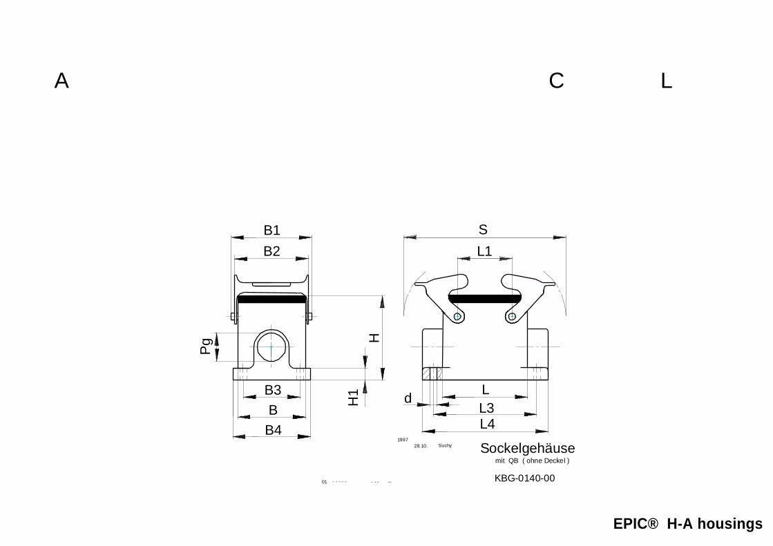
Sockelgehäuse
KBG-0140-00
HH
1
Pg
mit QB ( ohne Deckel )
SB2B1
L1
BB3
B4L3
d L
L41997
28.10. Suchy
01 - - - - - - - - --
A CL
EPIC® H-A housings

Benennung Art. Nr. Art. Nr. Kabel Eingang
Description part No. part No. Cable entry PG L L1 L3 L4 B B1 B2 B3 B4 H H1 S dDésignation N° art. N° art. sortie
H-A 32 SGRL 21 ZW. 10482000 2 21 82 49,6 94 106 56 70,8 66 46 57 75 4 124,5 5,5H-A 32 SGRL 29 ZW. 10482100 2 29 82 49,6 94 106 56 70,8 66 46 57 75 4 124,5 5,5H-A 32 SGRL-K 21 ZW. 70508200 2 21 82 49,6 94 106 56 70,8 66 46 57 75 4 124,5 5,5H-A 32 SGRL-K 29 ZW. 70508400 2 29 82 49,6 94 106 56 70,8 66 46 57 75 4 124,5 5,5H-A 32 SGR 21 ZW. 10474000 1 21 82 49,6 94 106 56 70,8 66 46 57 75 4 124,5 5,5H-A 32 SGR 29 ZW. 10474100 1 29 82 49,6 94 106 56 70,8 66 46 57 75 4 124,5 5,5H-A 32 SGR-K 21 ZW. 70507200 1 21 82 49,6 94 106 56 70,8 66 46 57 75 4 124,5 5,5H-A 32 SGR-K 29 ZW. 70507400 1 29 82 49,6 94 106 56 70,8 66 46 57 75 4 124,5 5,5H-A 48 SGRL 29 ZW. 10634800 2 29 93,5 64,5 112 124,5 79 91 87,8 67 81 72 5 136,5 5,5H-A 48 SGR 29 ZW. 10633800 1 29 93,5 64,5 112 124,5 79 91 87,8 67 81 72 5 136,5 5,5
A CL

HH
1
Sockelgehäuse
Pg
L2
KAG-0160-00
199727.10. Suchy
S
mit LB
L3d
L4B3B
B4
L1
L
01 - - - - - - - - --
A CL
EPIC® H-A housings

Benennung Art. Nr. Art. Nr. Kabel Eingang
Description part No. part No. Cable entry PG L L1 L2 L3 L4 B B3 B4 B5 H H1 S dDésignation N° art. N° art. sortie
H-A 10 SGRL-LB 16 ZW. 10450100 2 16 63 74,4 71,4 48 80 29,5 40 50 57 3,5 36,5 4,5H-A 10 SGRL-LB 21 ZW. 10450000 2 21 63 74,4 71,4 48 80 29,5 40 50 57 3,5 36,5 4,5H-A 10 SGRL-LB-K 16 ZW. 70448200 2 16 63 74,4 71,4 48 80 29,5 40 50 57 3,5 36,5 4,5H-A 10 SGRL-LB-K 21 ZW. 70448400 2 21 63 74,4 71,4 48 80 29,5 40 50 57 3,5 36,5 4,5H-A 10 SGR-LB 16 ZW. 10448100 1 16 63 74,4 71,4 48 80 29,5 40 50 57 3,5 36,5 4,5H-A 10 SGR-LB 21 ZW. 10448000 1 21 63 74,4 71,4 48 80 29,5 40 50 57 3,5 36,5 4,5H-A 10 SGR-LB-K 16 ZW. 70447200 1 16 63 74,4 71,4 48 80 29,5 40 50 57 3,5 36,5 4,5H-A 10 SGR-LB-K 21 ZW. 70447400 1 21 63 74,4 71,4 48 80 29,5 40 50 57 3,5 36,5 4,5H-A 16 SGRL-LB 16 ZW. 10568100 2 16 79 90,4 87,8 64 96 29,5 40 50 57 3,5 36,5 4,5H-A 16 SGRL-LB 21 ZW. 10568000 2 21 79 90,4 87,8 64 96 29,5 40 50 57 3,5 36,5 4,5H-A 16 SGRL-LB-K 16 ZW. 70478200 2 16 79 90,4 87,8 64 96 29,5 40 50 57 3,5 36,5 4,5H-A 16 SGRL-LB-K 21 ZW. 70478400 2 21 79 90,4 87,8 64 96 29,5 40 50 57 3,5 36,5 4,5H-A 16 SGR-LB 16 ZW. 10567100 1 16 79 90,4 87,8 64 96 29,5 40 50 57 3,5 36,5 4,5H-A 16 SGR-LB 21 ZW. 10567000 1 21 79 90,4 87,8 64 96 29,5 40 50 57 3,5 36,5 4,5H-A 16 SGR-LB-K 16 ZW. 70477200 1 16 79 90,4 87,8 64 96 29,5 40 50 57 3,5 36,5 4,5H-A 16 SGR-LB-K 21 ZW. 70477400 1 21 79 90,4 87,8 64 96 29,5 40 50 57 3,5 36,5 4,5
A CL

HH
1
Sockelgehäuse
Pg
L2
KAG-0180-00
199727.10. Suchy
S B5
mit LB und Deckel
L1
B3B
B4L3
d
L4
L
01 - - - - - - - - --
A CL
EPIC® H-A housings

Benennung Art. Nr. Art. Nr. Kabel Eingang
Description part No. part No. Cable entry PG L L1 L2 L3 L4 B B3 B4 B5 H H1 S dDésignation N° art. N° art. sortie
H-A 10 SDRL-LB 16 ZW. 70456200 2 16 63 74,4 71,4 48 80 29,5 40 50 25 57 3,5 36,5 4,5H-A 10 SDRL-LB 21 ZW. 70456400 2 21 63 74,4 71,4 48 80 29,5 40 50 25 57 3,5 36,5 4,5H-A 10 SDRL-LB-K 16 ZW. 70458200 2 16 63 74,4 71,4 48 80 29,5 40 50 25 57 3,5 36,5 4,5H-A 10 SDRL-LB-K 21 ZW. 70458400 2 21 63 74,4 71,4 48 80 29,5 40 50 25 57 3,5 36,5 4,5H-A 10 SDR-LB 16 ZW. 70455200 1 16 63 74,4 71,4 48 80 29,5 40 50 25 57 3,5 36,5 4,5H-A 10 SDR-LB 21 ZW. 70455400 1 21 63 74,4 71,4 48 80 29,5 40 50 25 57 3,5 36,5 4,5H-A 10 SDR-LB-K 16 ZW. 70457200 1 16 63 74,4 71,4 48 80 29,5 40 50 25 57 3,5 36,5 4,5H-A 10 SDR-LB-K 21 ZW. 70457400 1 21 63 74,4 71,4 48 80 29,5 40 50 25 57 3,5 36,5 4,5H-A 16 SDRL-LB 16 ZW. 70486200 2 16 79 90,4 87,8 64 96 29,5 40 50 25 57 3,5 36,5 4,5H-A 16 SDRL-LB 21 ZW. 70486400 2 21 79 90,4 87,8 64 96 29,5 40 50 25 57 3,5 36,5 4,5H-A 16 SDRL-LB-K 16 ZW. 70488200 2 16 79 90,4 87,8 64 96 29,5 40 50 25 57 3,5 36,5 4,5H-A 16 SDRL-LB-K 21 ZW. 70488400 2 21 79 90,4 87,8 64 96 29,5 40 50 25 57 3,5 36,5 4,5H-A 16 SDR-LB 16 ZW. 70485200 1 16 79 90,4 87,8 64 96 29,5 40 50 25 57 3,5 36,5 4,5H-A 16 SDR-LB 21 ZW. 70485400 1 21 79 90,4 87,8 64 96 29,5 40 50 25 57 3,5 36,5 4,5H-A 16 SDR-LB-K 16 ZW. 70487200 1 16 79 90,4 87,8 64 96 29,5 40 50 25 57 3,5 36,5 4,5H-A 16 SDR-LB-K 21 ZW. 70487400 1 21 79 90,4 87,8 64 96 29,5 40 50 25 57 3,5 36,5 4,5
A CL

Anbaugehäuse
KBG-0190-00
mit QB
H
H1
B2S
L1B2B1
L3d L
L4B
B3
199728.10. Suchy
01 - - - - - - - - --
A CL
EPIC® H-A housings

Benennung Art. Nr. Art. Nr.Description part No. part No. L L1 L3 L4 B B1 B2 B3 H H1 S dDésignation N° art. N° art.H-A 32 AG 10472000 82 49,6 92 102 56 70,8 66 42 25,4 4 124,5 4,3H-A 32 AG-K 70502500 82 49,6 92 102 56 70,8 66 42 25,4 4 124,5 4,3H-A 48 AG 10625500 93,5 64,5 110 124 79 91 87,8 65 30,3 5 136,5 5,5
A CL

H
Anbaugehäuse
L2
KAG-0200-00
199727.10. Suchy
S
B3B H
1
mit LB
L1
L3d
L4
L
01 - - - - - - - - --
A CL
EPIC® H-A housings

Benennung Art. Nr. Art. Nr.Description part No. part No. L L1 L2 L3 L4 B B3 H H1 S dDésignation N° art. N° art.H-A 10 AG-LB 10442000 63 74,4 71,4 70 81 29,5 17,5 25 3,5 36,5 3,6H-A 10 AG-LB-K 70442500 63 74,4 71,4 70 81 29,5 17,5 25 3,5 36,5 3,6H-A 16 AG-LB 10462000 79 90,4 87,8 86 96 29,5 17,5 25 3,5 36,5 3,6H-A 16 AG-LB-K 70472500 79 90,4 87,8 86 96 29,5 17,5 25 3,5 36,5 3,6
A CL

HH
1
Anbaugehäuse
L2
KAG-0210-00
199727.10. Suchy
S B5
mit LB und Deckel
L1
L3d
L4
L
BB3
01 - - - - - - - - --
A CL
EPIC® H-A housings

Benennung Art. Nr. Art. Nr.Description part No. part No. L L1 L2 L3 L4 B B3 B5 H H1 S dDésignation N° art. N° art.H-A 10 AD-LB 70444000 63 74,4 71,4 70 81 29,5 17,5 25 25 3,5 36,5 3,6H-A 10 AD-LB-K 70444500 63 74,4 71,4 70 81 29,5 17,5 25 25 3,5 36,5 3,6H-A 16 AD-LB 70474000 79 90,4 87,8 86 96 29,5 17,5 25 25 3,5 36,5 3,6H-A 16 AD-LB-K 70474500 79 90,4 87,8 86 96 29,5 17,5 25 25 3,5 36,5 3,6
A CL

Anbaugehäuse
KBG-0220-00
mit Deckel
199707.11. Suchy
01 - - - - - - - - - -
B5
H1
H
L3d
L4
LB
B3
L1
A CL
EPIC® H-A housings

Benennung Art. Nr. Art. Nr.Description part No. part No. L L1 L3 L4 B B3 B5 H H1 dDésignation N° art. N° art.H-A 32 AD-BO 70503000 82 49,6 92 102 56 42 29 25,4 4 4,3H-A 32 AD-BO-K 70503500 82 49,6 92 102 56 42 29 25,4 4 4,3
A CL

BB1
H
KBG-0010-00
Tüllengehäuse nieder
L1L
L2
TsPgTg
Pg15°Fa.-
199707.11. Suchy
01 - - - - - - - - --
Logo
A CL
EPIC® H-B housings

Benennung Art. Nr. Art. Nr. Kabel Eingang
Description part No. part No. Cable entry PG L L1 L2 B B1 HDésignation N° art. N° art. sortie
H-B 6 TS 13,5 ZW 10012000 seitlich, side, latérale 13,5 60 74,8 43 52H-B 6 TS 16 ZW. 10022000 seitlich, side, latérale 16 60 74,8 43 52H-B 6 TS-K 13,5 ZW 70023600 seitlich, side, latérale 13,5 60 74,8 43 52H-B 6 TS-K 16 ZW. 70023000 seitlich, side, latérale 16 60 74,8 43 52H-B 6 TG 13,5 ZW 10011000 gerade, top, verticale 13,5 60 74,8 43 52H-B 6 TG 16 ZW. 10021000 gerade, top, verticale 16 60 74,8 43 52H-B 6 TG-K 13,5 ZW 70021600 gerade, top, verticale 13,5 60 74,8 43 52H-B 6 TG-K 16 ZW. 70021000 gerade, top, verticale 16 60 74,8 43 52H-B 10 TS-RO 16 ZW. 10042900 seitlich, side, latérale 16 73 90 43 52H-B 10 TS-RO 21 ZW. 10042800 seitlich, side, latérale 21 73 90 43 52H-B 10 TS-RO-K 16 ZW. 70059000 seitlich, side, latérale 16 73 90 43 52H-B 10 TS-RO-K 21 ZW. 70059600 seitlich, side, latérale 21 73 90 43 52H-B 10 TG-RO 16 ZW. 10040900 gerade, top, verticale 16 73 90 43 52H-B 10 TG-RO 21 ZW. 10040700 gerade, top, verticale 21 73 90 43 52H-B 10 TG-RO-K 16 ZW. 70049000 gerade, top, verticale 16 73 90 43 52H-B 10 TG-RO-K 21 ZW. 70049600 gerade, top, verticale 21 73 90 43 52H-B 10 TS 16 ZW. 10042000 seitlich, side, latérale 16 73 27 43 57,8 52H-B 10 TS 21 ZW. 10042100 seitlich, side, latérale 21 73 27 43 57,8 52H-B 10 TS-K 16 ZW. 70053000 seitlich, side, latérale 16 73 27 43 57,8 52H-B 10 TS-K 21 ZW. 70053200 seitlich, side, latérale 21 73 27 43 57,8 52H-B 10 TG 16 ZW. 10040000 gerade, top, verticale 16 73 27 43 57,8 52H-B 10 TG 21 ZW. 10040100 gerade, top, verticale 21 73 27 43 57,8 52H-B 10 TG-K 16 ZW. 70051000 gerade, top, verticale 16 73 27 43 57,8 52H-B 10 TG-K 21 ZW. 70051200 gerade, top, verticale 21 73 27 43 57,8 52H-B 16 TS-RO 21 ZW. 10082900 seitlich, side, latérale 21 93,3 110 43 61H-B 16 TS-RO-K 21 ZW. 70109000 seitlich, side, latérale 21 93,3 110 43 61H-B 16 TG-RO 21 ZW. 10080900 gerade, top, verticale 21 93,3 110 43 61H-B 16 TG-RO-K 21 ZW. 70099000 gerade, top, verticale 21 93,3 110 43 61H-B 16 TS 21 ZW. 10082000 seitlich, side, latérale 21 93,3 47,5 43 57,8 61H-B 16 TS-K 21 ZW. 70103000 seitlich, side, latérale 21 93,3 47,5 43 57,8 61H-B 16 TG 21 ZW. 10080000 gerade, top, verticale 21 93,3 47,5 43 57,8 61H-B 16 TG-K 21 ZW. 70101000 gerade, top, verticale 21 93,3 47,5 43 57,8 61H-B 24 TS-RO 21 ZW. 10113900 seitlich, side, latérale 21 120 137 43 61H-B 24 TS-RO 29 ZW. 10123900 seitlich, side, latérale 29 120 137 43 61H-B 24 TS-RO-K 21 ZW. 70159000 seitlich, side, latérale 21 120 137 43 61H-B 24 TS-RO-K 29 ZW. 70159200 seitlich, side, latérale 29 120 137 43 61H-B 24 TG-RO 21 ZW. 10121900 gerade, top, verticale 21 120 137 43 61H-B 24 TG-RO 29 ZW. 10111900 gerade, top, verticale 29 120 137 43 61H-B 24 TG-RO-K 21 ZW. 70149000 gerade, top, verticale 21 120 137 43 61H-B 24 TG-RO-K 29 ZW. 70149200 gerade, top, verticale 29 120 137 43 61H-B 24 TS 21 ZW. 10113000 seitlich, side, latérale 21 120 74 43 57,8 61H-B 24 TS 29 ZW. 10123000 seitlich, side, latérale 29 120 74 43 57,8 61H-B 24 TS-K 21 ZW. 70153000 seitlich, side, latérale 21 120 74 43 57,8 61H-B 24 TS-K 29 ZW. 70153200 seitlich, side, latérale 29 120 74 43 57,8 61H-B 24 TG 21 ZW. 10121000 gerade, top, verticale 21 120 74 43 57,8 61H-B 24 TG 29 ZW. 10111000 gerade, top, verticale 29 120 74 43 57,8 61H-B 24 TG-K 21 ZW. 70151000 gerade, top, verticale 21 120 74 43 57,8 61
A CL

Benennung Art. Nr. Art. Nr. Kabel Eingang
Description part No. part No. Cable entry PG L L1 L2 B B1 HDésignation N° art. N° art. sortie
H-B 24 TG-K 29 ZW. 70151200 gerade, top, verticale 29 120 74 43 57,8 61H-B 48 TS 29 ZW. 10158000 seitlich, side, latérale 29 132 152 90 105H-B 48 TS 36 ZW. 10159000 seitlich, side, latérale 36 132 152 90 105H-B 48 TS 42 ZW. 10160000 seitlich, side, latérale 42 132 152 90 105H-B 48 TG 29 ZW. 10155000 gerade, top, verticale 29 132 152 90 105H-B 48 TG 36 ZW. 10156000 gerade, top, verticale 36 132 152 90 105H-B 48 TG 42 ZW. 10157000 gerade, top, verticale 42 132 152 90 105
A CL

L1LL2
TsTg
BB1
H
Pg
KBG-0020-00
LogoFa.-
Tüllengehäuse
3°
Pg
199728.10. Suchy
01 - - - - - - - - --
A CL
EPIC® H-B housings
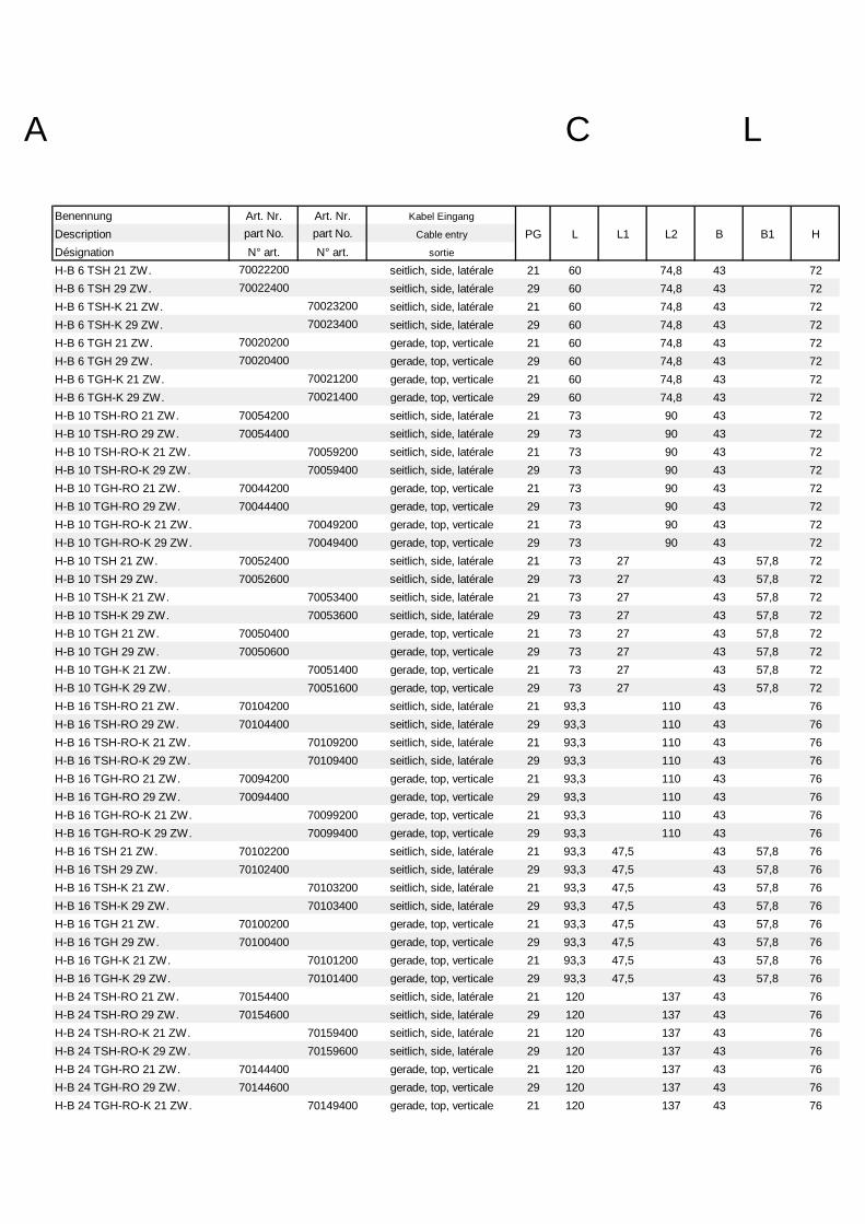
Benennung Art. Nr. Art. Nr. Kabel Eingang
Description part No. part No. Cable entry PG L L1 L2 B B1 HDésignation N° art. N° art. sortie
H-B 6 TSH 21 ZW. 70022200 seitlich, side, latérale 21 60 74,8 43 72H-B 6 TSH 29 ZW. 70022400 seitlich, side, latérale 29 60 74,8 43 72H-B 6 TSH-K 21 ZW. 70023200 seitlich, side, latérale 21 60 74,8 43 72H-B 6 TSH-K 29 ZW. 70023400 seitlich, side, latérale 29 60 74,8 43 72H-B 6 TGH 21 ZW. 70020200 gerade, top, verticale 21 60 74,8 43 72H-B 6 TGH 29 ZW. 70020400 gerade, top, verticale 29 60 74,8 43 72H-B 6 TGH-K 21 ZW. 70021200 gerade, top, verticale 21 60 74,8 43 72H-B 6 TGH-K 29 ZW. 70021400 gerade, top, verticale 29 60 74,8 43 72H-B 10 TSH-RO 21 ZW. 70054200 seitlich, side, latérale 21 73 90 43 72H-B 10 TSH-RO 29 ZW. 70054400 seitlich, side, latérale 29 73 90 43 72H-B 10 TSH-RO-K 21 ZW. 70059200 seitlich, side, latérale 21 73 90 43 72H-B 10 TSH-RO-K 29 ZW. 70059400 seitlich, side, latérale 29 73 90 43 72H-B 10 TGH-RO 21 ZW. 70044200 gerade, top, verticale 21 73 90 43 72H-B 10 TGH-RO 29 ZW. 70044400 gerade, top, verticale 29 73 90 43 72H-B 10 TGH-RO-K 21 ZW. 70049200 gerade, top, verticale 21 73 90 43 72H-B 10 TGH-RO-K 29 ZW. 70049400 gerade, top, verticale 29 73 90 43 72H-B 10 TSH 21 ZW. 70052400 seitlich, side, latérale 21 73 27 43 57,8 72H-B 10 TSH 29 ZW. 70052600 seitlich, side, latérale 29 73 27 43 57,8 72H-B 10 TSH-K 21 ZW. 70053400 seitlich, side, latérale 21 73 27 43 57,8 72H-B 10 TSH-K 29 ZW. 70053600 seitlich, side, latérale 29 73 27 43 57,8 72H-B 10 TGH 21 ZW. 70050400 gerade, top, verticale 21 73 27 43 57,8 72H-B 10 TGH 29 ZW. 70050600 gerade, top, verticale 29 73 27 43 57,8 72H-B 10 TGH-K 21 ZW. 70051400 gerade, top, verticale 21 73 27 43 57,8 72H-B 10 TGH-K 29 ZW. 70051600 gerade, top, verticale 29 73 27 43 57,8 72H-B 16 TSH-RO 21 ZW. 70104200 seitlich, side, latérale 21 93,3 110 43 76H-B 16 TSH-RO 29 ZW. 70104400 seitlich, side, latérale 29 93,3 110 43 76H-B 16 TSH-RO-K 21 ZW. 70109200 seitlich, side, latérale 21 93,3 110 43 76H-B 16 TSH-RO-K 29 ZW. 70109400 seitlich, side, latérale 29 93,3 110 43 76H-B 16 TGH-RO 21 ZW. 70094200 gerade, top, verticale 21 93,3 110 43 76H-B 16 TGH-RO 29 ZW. 70094400 gerade, top, verticale 29 93,3 110 43 76H-B 16 TGH-RO-K 21 ZW. 70099200 gerade, top, verticale 21 93,3 110 43 76H-B 16 TGH-RO-K 29 ZW. 70099400 gerade, top, verticale 29 93,3 110 43 76H-B 16 TSH 21 ZW. 70102200 seitlich, side, latérale 21 93,3 47,5 43 57,8 76H-B 16 TSH 29 ZW. 70102400 seitlich, side, latérale 29 93,3 47,5 43 57,8 76H-B 16 TSH-K 21 ZW. 70103200 seitlich, side, latérale 21 93,3 47,5 43 57,8 76H-B 16 TSH-K 29 ZW. 70103400 seitlich, side, latérale 29 93,3 47,5 43 57,8 76H-B 16 TGH 21 ZW. 70100200 gerade, top, verticale 21 93,3 47,5 43 57,8 76H-B 16 TGH 29 ZW. 70100400 gerade, top, verticale 29 93,3 47,5 43 57,8 76H-B 16 TGH-K 21 ZW. 70101200 gerade, top, verticale 21 93,3 47,5 43 57,8 76H-B 16 TGH-K 29 ZW. 70101400 gerade, top, verticale 29 93,3 47,5 43 57,8 76H-B 24 TSH-RO 21 ZW. 70154400 seitlich, side, latérale 21 120 137 43 76H-B 24 TSH-RO 29 ZW. 70154600 seitlich, side, latérale 29 120 137 43 76H-B 24 TSH-RO-K 21 ZW. 70159400 seitlich, side, latérale 21 120 137 43 76H-B 24 TSH-RO-K 29 ZW. 70159600 seitlich, side, latérale 29 120 137 43 76H-B 24 TGH-RO 21 ZW. 70144400 gerade, top, verticale 21 120 137 43 76H-B 24 TGH-RO 29 ZW. 70144600 gerade, top, verticale 29 120 137 43 76H-B 24 TGH-RO-K 21 ZW. 70149400 gerade, top, verticale 21 120 137 43 76
A CL

Benennung Art. Nr. Art. Nr. Kabel Eingang
Description part No. part No. Cable entry PG L L1 L2 B B1 HDésignation N° art. N° art. sortie
H-B 24 TGH-RO-K 29 ZW. 70149600 gerade, top, verticale 29 120 137 43 76H-B 24 TSH 21 ZW. 70152400 seitlich, side, latérale 21 120 74 43 57,8 76H-B 24 TSH 29 ZW. 70152600 seitlich, side, latérale 29 120 74 43 57,8 76H-B 24 TSH-K 21 ZW. 70153400 seitlich, side, latérale 21 120 74 43 57,8 76H-B 24 TSH-K 29 ZW. 70153600 seitlich, side, latérale 29 120 74 43 57,8 76H-B 24 TGH 21 ZW. 70150400 gerade, top, verticale 21 120 74 43 57,8 76H-B 24 TGH 29 ZW. 70150600 gerade, top, verticale 29 120 74 43 57,8 76H-B 24 TGH-K 21 ZW. 70151400 gerade, top, verticale 21 120 74 43 57,8 76H-B 24 TGH-K 29 ZW. 70151600 gerade, top, verticale 29 120 74 43 57,8 76H-B 32 TS 29 ZW. 10136000 seitlich, side, latérale 29 93,5 64,5 79 89,5 95H-B 32 TG 29 ZW. 10134000 gerade, top, verticale 29 93,5 64,5 79 89,5 95
A CL

L1
B2
B
H
LS
Tüllengehäuse
KBG-0030-00
B11997
Suchy
mit QB
PgTsTg
Pg15°
LogoFa.-
07.11.
01 - - - - - - - - --
A CL
EPIC® H-B housings

A CLBenennung Art. Nr. Art. Nr. Kabel Eingang
Description part No. part No. Cable entry PG L L1 B B1 B2 H SDésignation N° art. N° art. sortie
H-B 10 TSB 16 ZW. 10045000 seitlich, side, latérale 16 73 27 43 57,8 53 52 116H-B 10 TSB-K 16 ZW. 70058000 seitlich, side, latérale 16 73 27 43 57,8 53 52 116H-B 10 TGB 16 ZW. 10041000 gerade, top, verticale 16 73 27 43 57,8 53 52 116H-B 10 TGB-K 16 ZW. 70056000 gerade, top, verticale 16 73 27 43 57,8 53 52 116H-B 16 TSB 21 ZW. 10083000 seitlich, side, latérale 21 93,3 47,5 43 57,8 53 61 136,5H-B 16 TSB-K 21 ZW. 70108000 seitlich, side, latérale 21 93,3 47,5 43 57,8 53 61 136,5H-B 16 TGB 21 ZW. 10081000 gerade, top, verticale 21 93,3 47,5 43 57,8 53 61 136,5H-B 16 TGB-K 21 ZW. 70106000 gerade, top, verticale 21 93,3 47,5 43 57,8 53 61 136,5H-B 24 TSB 21 ZW. 10114000 seitlich, side, latérale 21 120 74 43 57,8 53 61 163H-B 24 TSB 29 ZW. 10124000 seitlich, side, latérale 29 120 74 43 57,8 53 61 163H-B 24 TSB-K 21 ZW. 70158000 seitlich, side, latérale 21 120 74 43 57,8 53 61 163H-B 24 TSB-K 29 ZW. 70158200 seitlich, side, latérale 29 120 74 43 57,8 53 61 163H-B 24 TGB 21 ZW. 10122000 gerade, top, verticale 21 120 74 43 57,8 53 61 163H-B 24 TGB 29 ZW. 10112000 gerade, top, verticale 29 120 74 43 57,8 53 61 163H-B 24 TGB-K 21 ZW. 70156000 gerade, top, verticale 21 120 74 43 57,8 53 61 163H-B 24 TGB-K 29 ZW. 70156200 gerade, top, verticale 29 120 74 43 57,8 53 61 163

L1
B2
B
H
L
LogoFa.-
B1
Tüllengehäuse
KBG-0040-00
mit QB
TsTg Pg
3°
Pg
S
A CL
EPIC® H-B housings

Benennung Art. Nr. Art. Nr. Kabel Eingang
Description part No. part No. Cable entry PG L L1 B B1 B2 H SDésignation N° art. N° art. sortie
H-B 10 TSBH 21 ZW. 70057200 seitlich, side, latérale 21 73 27 43 57,8 53 72 116H-B 10 TSBH 29 ZW. 70057400 seitlich, side, latérale 29 73 27 43 57,8 53 72 116H-B 10 TSBH-K 21 ZW. 70058200 seitlich, side, latérale 21 73 27 43 57,8 53 72 116H-B 10 TSBH-K 29 ZW. 70058400 seitlich, side, latérale 29 73 27 43 57,8 53 72 116H-B 10 TGBH 21 ZW. 70055200 gerade, top, verticale 21 73 27 43 57,8 53 72 116H-B 10 TGBH 29 ZW. 70055400 gerade, top, verticale 29 73 27 43 57,8 53 72 116H-B 10 TGBH-K 21 ZW. 70056200 gerade, top, verticale 21 73 27 43 57,8 53 72 116H-B 10 TGBH-K 29 ZW. 70056400 gerade, top, verticale 29 73 27 43 57,8 53 72 116H-B 16 TSBH 21 ZW. 70107200 seitlich, side, latérale 21 93,3 47,5 43 57,8 53 76 136,5H-B 16 TSBH 29 ZW. 70107400 seitlich, side, latérale 29 93,3 47,5 43 57,8 53 76 136,5H-B 16 TSBH-K 21 ZW. 70108200 seitlich, side, latérale 21 93,3 47,5 43 57,8 53 76 136,5H-B 16 TSBH-K 29 ZW. 70108400 seitlich, side, latérale 29 93,3 47,5 43 57,8 53 76 136,5H-B 16 TGBH 21 ZW. 70105200 gerade, top, verticale 21 93,3 47,5 43 57,8 53 76 136,5H-B 16 TGBH 29 ZW. 70105400 gerade, top, verticale 29 93,3 47,5 43 57,8 53 76 136,5H-B 16 TGBH-K 21 ZW. 70106200 gerade, top, verticale 21 93,3 47,5 43 57,8 53 76 136,5H-B 16 TGBH-K 29 ZW. 70106400 gerade, top, verticale 29 93,3 47,5 43 57,8 53 76 136,5H-B 24 TSBH 21 ZW. 70157400 seitlich, side, latérale 21 120 74 43 57,8 53 76 163H-B 24 TSBH 29 ZW. 70157600 seitlich, side, latérale 29 120 74 43 57,8 53 76 163H-B 24 TSBH-K 21 ZW. 70158400 seitlich, side, latérale 21 120 74 43 57,8 53 76 163H-B 24 TSBH-K 29 ZW. 70158600 seitlich, side, latérale 29 120 74 43 57,8 53 76 163H-B 24 TGBH 21 ZW. 70155400 gerade, top, verticale 21 120 74 43 57,8 53 76 163H-B 24 TGBH 29 ZW. 70155600 gerade, top, verticale 29 120 74 43 57,8 53 76 163H-B 24 TGBH-K 21 ZW. 70156400 gerade, top, verticale 21 120 74 43 57,8 53 76 163H-B 24 TGBH-K 29 ZW. 70156600 gerade, top, verticale 29 120 74 43 57,8 53 76 163H-B 32 TSB 29 10136600 seitlich, side, latérale 29 93,5 64,5 79 91 87,8 95 136,5H-B 32 TGB 29 70205000 gerade, top, verticale 29 93,5 64,5 79 91 87,8 95 136,5
A CL

KBG-0070-00
07.11.1997
Suchy Kupplungsgehäusemit QB
H
Fa.Logo
SLL1
TgPg
15°
B1
B2B
01 - - - - - - - - - -
A CL
EPIC® H-B housings

Benennung Art. Nr. Art. Nr. Kabel Eingang
Description part No. part No. Cable entry PG L L1 B B1 B2 H SDésignation N° art. N° art. sortie
H-B 10 TBF 16 ZW. 10046000 gerade, top, verticale 16 73 27 43 57,8 53 54,8 116H-B 10 TBF 21 ZW. 70040200 gerade, top, verticale 21 73 27 43 57,8 53 54,8 116H-B 10 TBF-K 16 ZW. 70041000 gerade, top, verticale 16 73 27 43 57,8 53 54,8 116H-B 10 TBF-K 21 ZW. 70041200 gerade, top, verticale 21 73 27 43 57,8 53 54,8 116H-B 16 TBF 21 ZW. 10086000 gerade, top, verticale 21 93,3 47,5 43 57,8 53 63,8 136,5H-B 16 TBF-K 21 ZW. 70091000 gerade, top, verticale 21 93,3 47,5 43 57,8 53 63,8 136,5H-B 24 TBF 21 ZW. 10127000 gerade, top, verticale 21 120 74 43 57,8 53 63,8 163H-B 24 TBF 29 ZW. 10117000 gerade, top, verticale 29 120 74 43 57,8 53 63,8 163H-B 24 TBF-K 21 ZW. 70141000 gerade, top, verticale 21 120 74 43 57,8 53 63,8 163H-B 24 TBF-K 29 ZW. 70141200 gerade, top, verticale 29 120 74 43 57,8 53 63,8 163
A CL

KBG-0080-00
Kupplungsgehäuse
3°3°
Pg
LogoFa.-
LogoFa.-
L
S
L1BB2
B1
H
mit QB
199707.11. Suchy
01 - - - - - - - - --
A CL
EPIC® H-B housings

Benennung Art. Nr. Art. Nr. Kabel Eingang
Description part No. part No. Cable entry PG L L1 B B1 B2 H SDésignation N° art. N° art. sortie
H-B 10 TBFH 21 ZW. 70040400 gerade, top, verticale 21 73 27 43 57,8 53 74,8 116H-B 10 TBFH 29 ZW. 70040600 gerade, top, verticale 29 73 27 43 57,8 53 74,8 116H-B 10 TBFH-K 21 ZW. 70041400 gerade, top, verticale 21 73 27 43 57,8 53 74,8 116H-B 10 TBFH-K 29 ZW. 70041600 gerade, top, verticale 29 73 27 43 57,8 53 74,8 116H-B 16 TBFH 21 ZW. 70090200 gerade, top, verticale 21 93,3 47,5 43 57,8 53 78,8 136,5H-B 16 TBFH 29 ZW. 70090400 gerade, top, verticale 29 93,3 47,5 43 57,8 53 78,8 136,5H-B 16 TBFH-K 21 ZW. 70091200 gerade, top, verticale 21 93,3 47,5 43 57,8 53 78,8 136,5H-B 16 TBFH-K 29 ZW. 70091400 gerade, top, verticale 29 93,3 47,5 43 57,8 53 78,8 136,5H-B 24 TBFH 21 ZW. 70140400 gerade, top, verticale 21 120 74 43 57,8 53 78,8 163H-B 24 TBFH 29 ZW. 70140600 gerade, top, verticale 29 120 74 43 57,8 53 78,8 163H-B 24 TBFH-K 21 ZW. 70141400 gerade, top, verticale 21 120 74 43 57,8 53 78,8 163H-B 24 TBFH-K 29 ZW. 70141600 gerade, top, verticale 29 120 74 43 57,8 53 78,8 163H-B 32 TBFH 29 10139500 gerade, top, verticale 29 93,5 64,5 79 91 87,8 97 136,5
A CL

H Fa.Logo
B
TgPg
15°
KBG-0090-00
07.111997
Suchy Kupplungsgehäusemit LB
L1L2L
S
01 - - - - - - - - --
A CL
EPIC® H-B housings
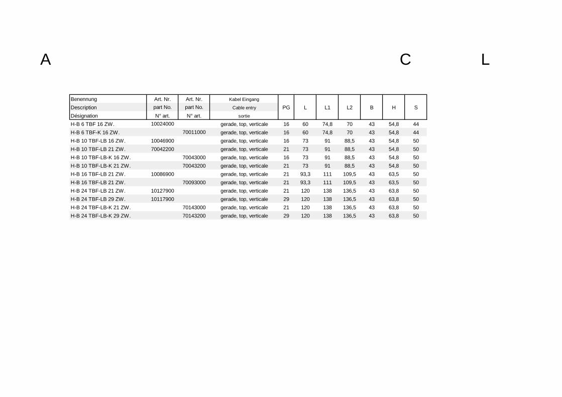
Benennung Art. Nr. Art. Nr. Kabel Eingang
Description part No. part No. Cable entry PG L L1 L2 B H SDésignation N° art. N° art. sortie
H-B 6 TBF 16 ZW. 10024000 gerade, top, verticale 16 60 74,8 70 43 54,8 44H-B 6 TBF-K 16 ZW. 70011000 gerade, top, verticale 16 60 74,8 70 43 54,8 44H-B 10 TBF-LB 16 ZW. 10046900 gerade, top, verticale 16 73 91 88,5 43 54,8 50H-B 10 TBF-LB 21 ZW. 70042200 gerade, top, verticale 21 73 91 88,5 43 54,8 50H-B 10 TBF-LB-K 16 ZW. 70043000 gerade, top, verticale 16 73 91 88,5 43 54,8 50H-B 10 TBF-LB-K 21 ZW. 70043200 gerade, top, verticale 21 73 91 88,5 43 54,8 50H-B 16 TBF-LB 21 ZW. 10086900 gerade, top, verticale 21 93,3 111 109,5 43 63,5 50H-B 16 TBF-LB 21 ZW. 70093000 gerade, top, verticale 21 93,3 111 109,5 43 63,5 50H-B 24 TBF-LB 21 ZW. 10127900 gerade, top, verticale 21 120 138 136,5 43 63,8 50H-B 24 TBF-LB 29 ZW. 10117900 gerade, top, verticale 29 120 138 136,5 43 63,8 50H-B 24 TBF-LB-K 21 ZW. 70143000 gerade, top, verticale 21 120 138 136,5 43 63,8 50H-B 24 TBF-LB-K 29 ZW. 70143200 gerade, top, verticale 29 120 138 136,5 43 63,8 50
A CL

3°3°3°
L
L1
TsPg
LogoFa.-
LogoFa.-
L2
H
KBG-0100-00
07.11.1997
SuchyKupplung mit LB
BS
01 - - - - - - - - - -
A CL
EPIC® H-B housings

Benennung Art. Nr. Art. Nr. Kabel Eingang
Description part No. part No. Cable entry PG L L1 L2 B H SDésignation N° art. N° art. sortie
H-B 6 TBFH 21 ZW. 70010200 gerade, top, verticale 21 60 74,8 70 43 74,8 44H-B 6 TBFH 29 ZW. 70010400 gerade, top, verticale 29 60 74,8 70 43 74,8 44H-B 6 TBFH-K 21 ZW 70011200 gerade, top, verticale 21 60 74,8 70 43 74,8 44H-B 6 TBFH-K 29 ZW. 70011400 gerade, top, verticale 29 60 74,8 70 43 74,8 44H-B 10 TBFH-LB 21 ZW. 70042400 gerade, top, verticale 21 73 91 88,5 43 74,8 50H-B 10 TBFH-LB 29 ZW. 70042600 gerade, top, verticale 29 73 91 88,5 43 74,8 50H-B 10 TBFH-LB-K 21 ZW. 70043400 gerade, top, verticale 21 73 91 88,5 43 74,8 50H-B 10 TBFH-LB-K 29 ZW. 70043600 gerade, top, verticale 29 73 91 88,5 43 74,8 50H-B 16 TBFH-LB 21 ZW. 70092200 gerade, top, verticale 21 93,3 111 109,5 43 78,8 50H-B 16 TBFH-LB 29 ZW. 70092400 gerade, top, verticale 29 93,3 111 109,5 43 78,8 50H-B 16 TBFH-LB-K 21 ZW. 70093200 gerade, top, verticale 21 93,3 111 109,5 43 78,8 50H-B 16 TBFH-LB-K 29 ZW. 70093400 gerade, top, verticale 29 93,3 111 109,5 43 78,8 50H-B 24 TBFH-LB 21 ZW. 70142400 gerade, top, verticale 21 120 138 136,5 43 78,8 50H-B 24 TBFH-LB 29 ZW. 70142600 gerade, top, verticale 29 120 138 136,5 43 78,8 50H-B 24 TBFH-LB-K 21 ZW. 70143400 gerade, top, verticale 21 120 138 136,5 43 78,8 50H-B 24 TBFH-LB-K 29 ZW. 70143600 gerade, top, verticale 29 120 138 136,5 43 78,8 50
A CL

Sockelgehäuse
KBG-0120-00
199707.11. Suchy
H
mit Deckel ( ohne Bügel )
L1
H1
Pg B5
L3d L
BB3
B4 L4
01 - - - - - - - - --
B1
A CL
EPIC® H-B housings

Benennung Art. Nr. Art. Nr. Kabel Eingang
Description part No. part No. Cable entry PG L L1 L3 L4 B B1 B3 B4 B5 H H1 dDésignation N° art. N° art. sortie
H-B 10 SDRL-BO 16 ZW. 10038000 2 16 73 27 82 94 43 57,8 40 54 25 57 4,5 5,5H-B 10 SDRL-BO-K 16 ZW. 70048000 2 16 73 27 82 94 43 57,8 40 54 25 57 4,5 5,5H-B 10 SDR-BO 16 ZW. 10036000 1 16 73 27 82 94 43 57,8 40 54 25 57 4,5 5,5H-B 10 SDR-BO-K 16 ZW. 70047000 1 16 73 27 82 94 43 57,8 40 54 25 57 4,5 5,5H-B 10 SDRLH-BO 21 ZW. 70046200 2 21 73 27 82 97 43 57,8 45 58 25 74 6 5,5H-B 10 SDRLH-BO 29 ZW. 70046400 2 29 73 27 82 97 43 57,8 45 58 25 74 6 5,5H-B 10 SDRLH-BO-K 21 ZW. 70048200 2 21 73 27 82 97 43 57,8 45 58 25 74 6 5,5H-B 10 SDRLH-BO-K 29 ZW. 70048400 2 29 73 27 82 97 43 57,8 45 58 25 74 6 5,5H-B 10 SDRH-BO 21 ZW. 70045200 1 21 73 27 82 97 43 57,8 45 58 25 74 6 5,5H-B 10 SDRH-BO 29 ZW. 70045400 1 29 73 27 82 97 43 57,8 45 58 25 74 6 5,5H-B 10 SDRH-BO-K 21 ZW. 70047200 1 21 73 27 82 97 43 57,8 45 58 25 74 6 5,5H-B 10 SDRH-BO-K 29 ZW. 70047400 1 29 73 27 82 97 43 57,8 45 58 25 74 6 5,5H-B 16 SDRL-BO 21 ZW. 70096000 2 21 93 47,5 105 117 43 45 57 25 64 4,5 5,5H-B 16 SDRL-BO-K 21 ZW. 70098000 2 21 93 47,5 105 117 43 45 57 25 64 4,5 5,5H-B 16 SDR-BO 21 ZW. 10076000 1 21 93 47,5 105 117 43 45 57 25 64 4,5 5,5H-B 16 SDR-BO-K 21 ZW. 70097000 1 21 93 47,5 105 117 43 45 57 25 64 4,5 5,5H-B 16 SDRLH-BO 21 ZW. 70096200 2 21 93,3 47,5 105 117 43 45 58 25 84 6 5,5H-B 16 SDRLH-BO 29 ZW. 70096400 2 29 93,3 47,5 105 117 43 45 58 25 84 6 5,5H-B 16 SDRLH-BO-K 21 ZW. 70098200 2 21 93,3 47,5 105 117 43 45 58 25 84 6 5,5H-B 16 SDRLH-BO-K 29 ZW. 70098400 2 29 93,3 47,5 105 117 43 45 58 25 84 6 5,5H-B 16 SDRH-BO 21 ZW. 70095200 1 21 93,3 47,5 105 117 43 45 58 25 84 6 5,5H-B 16 SDRH-BO 29 ZW. 70095400 1 29 93,3 47,5 105 117 43 45 58 25 84 6 5,5H-B 16 SDRH-BO-K 21 ZW. 70097200 1 21 93,3 47,5 105 117 43 45 58 25 84 6 5,5H-B 16 SDRH-BO-K 29 ZW. 70097400 1 29 93,3 47,5 105 117 43 45 58 25 84 6 5,5H-B 24 SDRL-BO 21 ZW. 10109000 2 21 120 74 132 144 43 57,8 45 57 25 64 4,5 5,5H-B 24 SDRL-BO-K 21 ZW. 70148000 2 21 120 74 132 144 43 57,8 45 57 25 64 4,5 5,5H-B 24 SDR-BO 21 ZW. 10107000 1 21 120 74 132 144 43 57,8 45 57 25 64 4,5 5,5
A CL

Benennung Art. Nr. Art. Nr. Kabel Eingang
Description part No. part No. Cable entry PG L L1 L3 L4 B B1 B3 B4 B5 H H1 dDésignation N° art. N° art. sortie
H-B 24 SDR-BO-K 21 ZW. 70147000 1 21 120 74 132 144 43 57,8 45 57 25 64 4,5 5,5H-B 24 SDRLH-BO 21 ZW. 70146200 2 21 120 74 132 144 43 57,8 45 58 25 84 6 5,5H-B 24 SDRLH-BO 29 ZW. 70146400 2 29 120 74 132 144 43 57,8 45 58 25 84 6 5,5H-B 24 SDRLH-BO-K 21 ZW. 70148200 2 21 120 74 132 144 43 57,8 45 58 25 84 6 5,5H-B 24 SDRLH-BO-K 29 ZW. 70148400 2 29 120 74 132 144 43 57,8 45 58 25 84 6 5,5H-B 24 SDRH-BO 21 ZW. 70145200 1 21 120 74 132 144 43 57,8 45 58 25 84 6 5,5H-B 24 SDRH-BO 29 ZW. 70145400 1 29 120 74 132 144 43 57,8 45 58 25 84 6 5,5H-B 24 SDRH-BO-K 21 ZW. 70147200 1 21 120 74 132 144 43 57,8 45 58 25 84 6 5,5H-B 24 SDRH-BO-K 29 ZW. 70147400 1 29 120 74 132 144 43 57,8 45 58 25 84 6 5,5
A CL
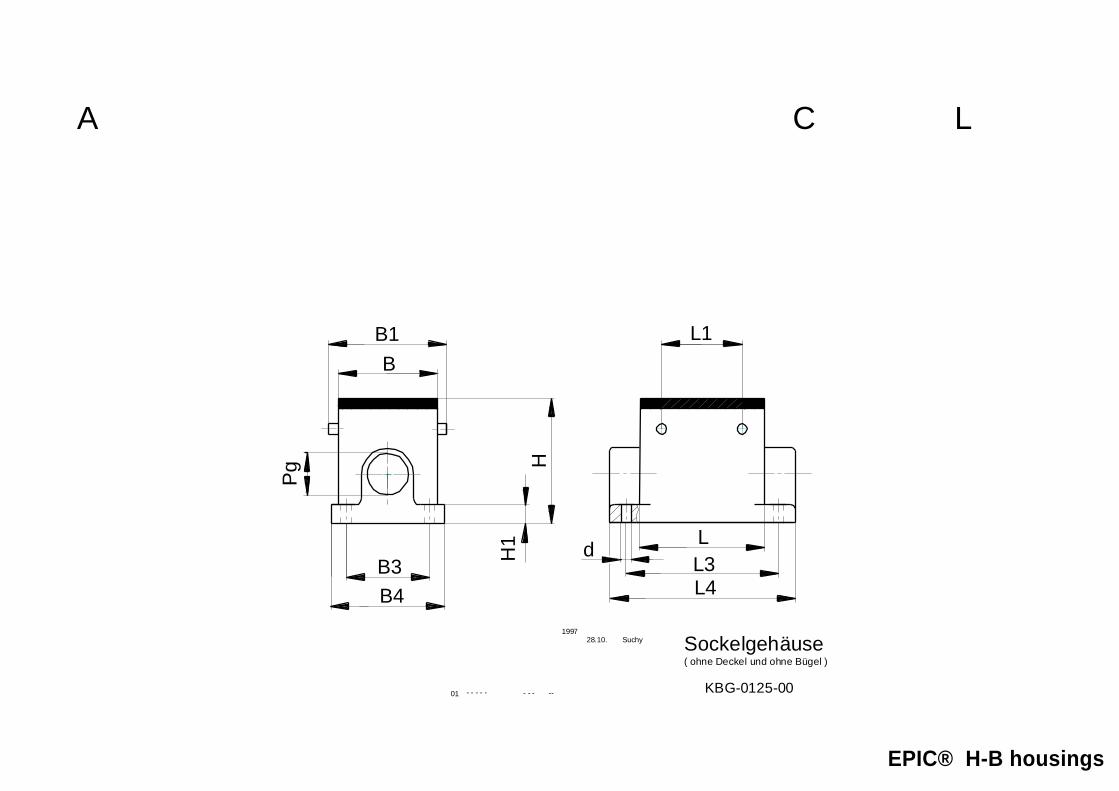
Sockelgehäuse
KBG-0125-00
( ohne Deckel und ohne Bügel )
HH
1
Pg
B1 L1
B3B4
L3d L
L4
B
199728.10. Suchy
01 - - - - - - - - --
A CL
EPIC® H-B housings

Benennung Art. Nr. Art. Nr. Kabel Eingang
Description part No. part No. Cable entry PG L L1 L3 L4 B B1 B3 B4 H H1 dDésignation N° art. N° art. sortie
H-B 32 SGRL-BO 29 ZW. 10138300 2 29 93,5 64,5 112 124,5 79 89,5 67 81 72 5 5,5H-B 32 SGR-BO 29 ZW. 10137300 1 29 93,5 64,5 112 124,5 79 89,5 67 81 72 5 5,5
A CL

Sockelgehäuse
KBG-0140-00
HH
1
Pg
mit QB ( ohne Deckel )
SB2B1
L1
BB3
B4L3
d L
L41997
28.10. Suchy
01 - - - - - - - - --
A CL
EPIC® H-B housings

Benennung Art. Nr. Art. Nr. Kabel Eingang
Description part No. part No. Cable entry PG L L1 L3 L4 B B1 B2 B3 B4 H H1 S dDésignation N° art. N° art. sortie
H-B 10 SGRL 16 ZW. 10035000 2 16 73 27 82 94 43 57,8 53 40 54 57 4,5 116 5,5H-B 10 SGRL-K 16 ZW. 70038000 2 16 73 27 82 94 43 57,8 53 40 54 57 4,5 116 5,5H-B 10 SGR 16 ZW. 10034000 1 16 73 27 82 94 43 57,8 53 40 54 57 4,5 116 5,5H-B 10 SGR-K 16 ZW. 70037000 1 16 73 27 82 94 43 57,8 53 40 54 57 4,5 116 5,5H-B 10 SGRLH 21 ZW. 70036200 2 21 73 27 82 97 43 57,8 53 45 58 74 6 116 5,5H-B 10 SGRLH 29 ZW. 70036400 2 29 73 27 82 97 43 57,8 53 45 58 74 6 116 5,5H-B 10 SGRLH-K 21 ZW. 70038200 2 21 73 27 82 97 43 57,8 53 45 58 74 6 116 5,5H-B 10 SGRLH-K 29 ZW. 70038400 2 29 73 27 82 97 43 57,8 53 45 58 74 6 116 5,5H-B 10 SGRH 21 ZW. 70035200 1 21 73 27 82 97 43 57,8 53 45 58 74 6 116 5,5H-B 10 SGRH 29 ZW. 70035400 1 29 73 27 82 97 43 57,8 53 45 58 74 6 116 5,5H-B 10 SGRH-K 21 ZW. 70037200 1 21 73 27 82 97 43 57,8 53 45 58 74 6 116 5,5H-B 10 SGRH-K 29 ZW. 70037400 1 29 73 27 82 97 43 57,8 53 45 58 74 6 116 5,5H-B 16 SGRL 21 ZW. 10075000 2 21 93 47,5 105 117 43 57,8 53 45 57 64 4,5 136,5 5,5H-B 16 SGRL-K 21 ZW. 70088000 2 21 93 47,5 105 117 43 57,8 53 45 57 64 4,5 136,5 5,5H-B 16 SGR 21 ZW. 10074000 1 21 93 47,5 105 117 43 57,8 53 45 57 64 4,5 136,5 5,5H-B 16 SGR-K 21 ZW. 70087000 1 21 93 47,5 105 117 43 57,8 53 45 57 64 4,5 136,5 5,5H-B 16 SGRLH 21 ZW. 70086200 2 21 93,3 47,5 105 117 43 57,8 53 45 58 84 6 136,5 5,5H-B 16 SGRLH 29 ZW. 70086400 2 29 93,3 47,5 105 117 43 57,8 53 45 58 84 6 136,5 5,5H-B 16 SGRLH-K 21 ZW. 70088200 2 21 93,3 47,5 105 117 43 57,8 53 45 58 84 6 136,5 5,5H-B 16 SGRLH-K 29 ZW. 70088400 2 29 93,3 47,5 105 117 43 57,8 53 45 58 84 6 136,5 5,5H-B 16 SGRH 21 ZW. 70085200 1 21 93,3 47,5 105 117 43 57,8 53 45 58 84 6 136,5 5,5H-B 16 SGRH 29 ZW. 70085400 1 29 93,3 47,5 105 117 43 57,8 53 45 58 84 6 136,5 5,5H-B 16 SGRH-K 21 ZW. 70087200 1 21 93,3 47,5 105 117 43 57,8 53 45 58 84 6 136,5 5,5H-B 16 SGRH-K 29 ZW. 70087400 1 29 93,3 47,5 105 117 43 57,8 53 45 58 84 6 136,5 5,5H-B 24 SGRL 16 ZW. 10105000 2 21 120 74 132 144 43 57,8 53 45 57 64 4,5 163 5,5H-B 24 SGRL-K 16 ZW. 70138000 2 21 120 74 132 144 43 57,8 53 45 57 64 4,5 163 5,5H-B 24 SGR 16 ZW. 10104000 1 21 120 74 132 144 43 57,8 53 45 57 64 4,5 163 5,5
A CL

Benennung Art. Nr. Art. Nr. Kabel Eingang
Description part No. part No. Cable entry PG L L1 L3 L4 B B1 B2 B3 B4 H H1 S dDésignation N° art. N° art. sortie
H-B 24 SGR-K 16 ZW. 70137000 1 21 120 74 132 144 43 57,8 53 45 57 64 4,5 163 5,5H-B 24 SGRLH 21 ZW. 70136200 2 21 120 74 132 144 43 57,8 53 45 58 84 6 163 5,5H-B 24 SGRLH-K 29 ZW. 70136400 2 29 120 74 132 144 43 57,8 53 45 58 84 6 163 5,5H-B 24 SGRLH 21 ZW. 70138200 2 21 120 74 132 144 43 57,8 53 45 58 84 6 163 5,5H-B 24 SGRLH-K 29 ZW. 70138400 2 29 120 74 132 144 43 57,8 53 45 58 84 6 163 5,5H-B 24 SGRH 21 ZW. 70135200 1 21 120 74 132 144 43 57,8 53 45 58 84 6 163 5,5H-B 24 SGRH-K 29 ZW. 70135400 1 29 120 74 132 144 43 57,8 53 45 58 84 6 163 5,5H-B 24 SGRLH 21 ZW. 70137200 1 21 120 74 132 144 43 57,8 53 45 58 84 6 163 5,5H-B 24 SGRLH-K 29 ZW. 70137400 1 29 120 74 132 144 43 57,8 53 45 58 84 6 163 5,5H-B 32 SGRL 29 ZW. 10138000 2 29 93,5 64,5 112 124,5 79 91 87,8 67 81 72 5 136,5 5,5H-B 32 SGR 29 ZW. 10137000 1 29 93,5 64,5 112 124,5 79 91 87,8 67 81 72 5 136,5 5,5
A CL

Sockelgehäuse
L2
KBG-0160-00
HH
1
Pg
S
mit LB
L1
199707.11. Suchy
01 - - - - - - - - --
L3d L
L4B
B3
B4
A CL
EPIC® H-B housings

Benennung Art. Nr. Art. Nr. Kabel Eingang
Description part No. part No. Cable entry PG L L1 L2 L3 L4 B B3 B4 H H1 S dDésignation N° art. N° art. sortie
H-B 6 SGRL 16 ZW. 10006000 2 16 60 74,8 70 70 84 43 40 54 54 4,5 44 5,5H-B 6 SGRL-K 16 ZW. 70008000 2 16 60 74,8 70 70 84 43 40 54 54 4,5 44 5,5H-B 6 SGR 16 ZW. 10005000 1 16 60 74,8 70 70 84 43 40 54 54 4,5 44 5,5H-B 6 SGR-K 16 ZW. 70007000 1 16 60 74,8 70 70 84 43 40 54 54 4,5 44 5,5H-B 6 SGRLH 21 ZW. 70006200 2 21 60 74,8 70 70 84 43 45 58 74 6 44 5,5H-B 6 SGRLH 29 ZW. 70006400 2 29 60 74,8 70 70 84 43 45 58 74 6 44 5,5H-B 6 SGRLH-K 21 ZW. 70008200 2 21 60 74,8 70 70 84 43 45 58 74 6 44 5,5H-B 6 SGRLH-K 29 ZW. 70008400 2 29 60 74,8 70 70 84 43 45 58 74 6 44 5,5H-B 6 SGRH 21 ZW. 70005200 1 21 60 74,8 70 70 84 43 45 58 74 6 44 5,5H-B 6 SGRH 29 ZW. 70005400 1 29 60 74,8 70 70 84 43 45 58 74 6 44 5,5H-B 6 SGRH-K 21 ZW. 70007200 1 21 60 74,8 70 70 84 43 45 58 74 6 44 5,5H-B 6 SGRH-K 29 ZW. 70007400 1 29 60 74,8 70 70 84 43 45 58 74 6 44 5,5H-B 10 SGRL-LB 16 ZW. 10035900 2 16 73 91 88,5 82 94 43 40 54 57 4,5 50 5,5H-B 10 SGRL-LB-K 16 ZW. 70063000 2 16 73 91 88,5 82 94 43 40 54 57 4,5 50 5,5H-B 10 SGR-LB 16 ZW. 10034900 1 16 73 91 88,5 82 94 43 40 54 57 4,5 50 5,5H-B 10 SGR-LB-K 16 ZW. 70062000 1 16 73 91 88,5 82 94 43 40 54 57 4,5 50 5,5H-B 10 SGRLH-LB 21 ZW. 70061200 2 21 73 91 88,5 82 97 43 45 58 74 6 50 5,5H-B 10 SGRLH-LB 29 ZW. 70061400 2 29 73 91 88,5 82 97 43 45 58 74 6 50 5,5H-B 10 SGRLH-LB-K 21 ZW. 70063200 2 21 73 91 88,5 82 97 43 45 58 74 6 50 5,5H-B 10 SGRLH-LB-K29 ZW. 70063400 2 29 73 91 88,5 82 97 43 45 58 74 6 50 5,5H-B 10 SGRH-LB 21 ZW. 70060200 1 21 73 91 88,5 82 97 43 45 58 74 6 50 5,5H-B 10 SGRH-LB 29 ZW. 70060400 1 29 73 91 88,5 82 97 43 45 58 74 6 50 5,5H-B 10 SGRH-LB-K 21 ZW. 70062200 1 21 73 91 88,5 82 97 43 45 58 74 6 50 5,5H-B 10 SGRH-LB-K 29 ZW. 70062400 1 29 73 91 88,5 82 97 43 45 58 74 6 50 5,5H-B 16 SGRL-LB 21 ZW. 10075900 2 21 93 111 109,5 105 117 43 45 57 64 4,5 50 5,5H-B 16 SGRL-LB-K 21 ZW. 70113000 2 21 93 111 109,5 105 117 43 45 57 64 4,5 50 5,5H-B 16 SGR-LB 21 ZW. 10074900 1 21 93 111 109,5 105 117 43 45 57 64 4,5 50 5,5
A CL

Benennung Art. Nr. Art. Nr. Kabel Eingang
Description part No. part No. Cable entry PG L L1 L2 L3 L4 B B3 B4 H H1 S dDésignation N° art. N° art. sortie
H-B 16 SGR-LB-K 21 ZW. 70112000 1 21 93 111 109,5 105 117 43 45 57 64 4,5 50 5,5H-B 16 SGRLH-LB 21 ZW. 70111200 2 21 93,3 111 109,5 105 117 43 45 58 84 6 50 5,5H-B 16 SGRLH-LB 29 ZW. 70111400 2 29 93,3 111 109,5 105 117 43 45 58 84 6 50 5,5H-B 16 SGRLH-LB-K 21 ZW. 70113200 2 21 93,3 111 109,5 105 117 43 45 58 84 6 50 5,5H-B 16 SGRLH-LB-K 29 ZW. 70113400 2 29 93,3 111 109,5 105 117 43 45 58 84 6 50 5,5H-B 16 SGRH-LB 21 ZW. 70110200 1 21 93,3 111 109,5 105 117 43 45 58 84 6 50 5,5H-B 16 SGRH-LB 29 ZW. 70110400 1 29 93,3 111 109,5 105 117 43 45 58 84 6 50 5,5H-B 16 SGRH-LB-K 21 ZW. 70112200 1 21 93,3 111 109,5 105 117 43 45 58 84 6 50 5,5H-B 16 SGRH-LB-K 29 ZW. 70112400 1 29 93,3 111 109,5 105 117 43 45 58 84 6 50 5,5H-B 24 SGRL-LB 21 ZW. 10105900 2 21 120 138 136,5 132 144 43 45 57 64 4,5 50 5,5H-B 24 SGRL-LB-K 21 ZW. 70163000 2 21 120 138 136,5 132 144 43 45 57 64 4,5 50 5,5H-B 24 SGR-LB 16 ZW. 10104900 1 21 120 138 136,5 132 144 43 45 57 64 4,5 50 5,5H-B 24 SGR-LB-K 16 ZW. 70162000 1 21 120 138 136,5 132 144 43 45 57 64 4,5 50 5,5H-B 24 SGRLH-LB 21 ZW. 70161200 2 21 120 138 136,5 132 144 43 45 57,8 84 6 50 5,5H-B 24 SGRLH-LB 29 ZW. 70161400 2 29 120 138 136,5 132 144 43 45 57,8 84 6 50 5,5H-B 24 SGRLH-LB-K 21 ZW. 70163200 2 21 120 138 136,5 132 144 43 45 57,8 84 6 50 5,5H-B 24 SGRLH-LB-K29 ZW. 70163400 2 29 120 138 136,5 132 144 43 45 57,8 84 6 50 5,5H-B 24 SGRH-LB 21 ZW. 70160200 1 21 120 138 136,5 132 144 43 45 57,8 84 6 50 5,5H-B 24 SGRH-LB 29 ZW. 70160400 1 29 120 138 136,5 132 144 43 45 57,8 84 6 50 5,5H-B 24 SGRH-LB-K 21 ZW. 70162200 1 21 120 138 136,5 132 144 43 45 57,8 84 6 50 5,5H-B 24 SGRH-LB-K 29 ZW. 70162400 1 29 120 138 136,5 132 144 43 45 57,8 84 6 50 5,5H-B 48 SGRL 29 ZW. 10166000 2 29 132 152 139,5 111 132 90 106 120 100 12 105 6,5H-B 48 SGRL 36 ZW. 10166100 2 36 132 152 139,5 111 132 90 106 120 100 12 105 6,5H-B 48 SGR 29 ZW. 10165000 1 29 132 152 139,5 111 132 90 106 120 100 12 105 6,5H-B 48 SGR 36 ZW. 10165100 1 36 132 152 139,5 111 132 90 106 120 100 12 105 6,5
A CL

Sockelgehäuse
L2
KBG-0180-00
HH
1
Pg
S
mit LB und Deckel
B5
L1
L3d L
L41997
07.11. Suchy
01 - - - - - - - - --
BB3
B4
A CL
EPIC® H-B housings

Benennung Art. Nr. Art. Nr. Kabel Eingang
Description part No. part No. Cable entry PG L L1 L2 L3 L4 B B3 B4 B5 H H1 S dDésignation N° art. N° art. sortie
H-B 6 SDRL 16 ZW. 10009000 2 16 60 74,8 70 70 84 43 40 54 25 54 4 44 5,5H-B 6 SDRL-K 16 ZW. 70018000 2 16 60 74,8 70 70 84 43 40 54 25 54 4,5 44 5,5H-B 6 SDR 16 ZW. 10007000 1 16 60 74,8 70 70 84 43 40 54 25 54 4,5 44 5,5H-B 6 SDR-K 16 ZW. 70017000 1 16 60 74,8 70 70 84 43 40 54 25 54 4,5 44 5,5H-B 6 SDHRL-LB 21 ZW. 70016200 2 21 60 74,8 70 70 84 43 45 58 25 74 6 44 5,5H-B 6 SDHRL-LB 29 ZW. 70016400 2 29 60 74,8 70 70 84 43 45 58 25 74 6 44 5,5H-B 6 SDHRL-LB-K 21 ZW. 70018200 2 21 60 74,8 70 70 84 43 45 58 25 74 6 44 5,5H-B 6 SDHRL-LB-K 29 ZW. 70018400 2 29 60 74,8 70 70 84 43 45 58 25 74 6 44 5,5H-B 6 SDHR-LB 21 ZW. 70015200 1 21 60 74,8 70 70 84 43 45 58 25 74 6 44 5,5H-B 6 SDHR-LB 29 ZW. 70015400 1 29 60 74,8 70 70 84 43 45 58 25 74 6 44 5,5H-B 6 SDHR-LB-K 21 ZW. 70017200 1 21 60 74,8 70 70 84 43 45 58 25 74 6 44 5,5H-B 6 SDHR-LB-K 29 ZW. 70017400 1 29 60 74,8 70 70 84 43 45 58 25 74 6 44 5,5H-B 10 SDRL-LB 16 ZW. 10038900 2 16 73 91 88,5 82 94 43 40 54 25 57 4,5 50 5,5H-B 10 SDRL-LB-K 16 ZW. 70067000 2 16 73 91 88,5 82 94 43 40 54 25 57 4,5 50 5,5H-B 10 SDR-LB 16 ZW. 10036900 1 16 73 91 88,5 82 94 43 40 54 25 57 4,5 50 5,5H-B 10 SDR-LB-K 16 ZW. 70066000 1 16 73 91 88,5 82 94 43 40 54 25 57 4,5 50 5,5H-B 10 SDRLH-LB 21 ZW. 70065200 2 21 73 91 88,5 82 97 43 45 58 25 74 6 50 5,5H-B 10 SDRLH-LB 29 ZW. 70065400 2 29 73 91 88,5 82 97 43 45 58 25 74 6 50 5,5H-B 10 SDRLH-LB-K 21 ZW. 70067200 2 21 73 91 88,5 82 97 43 45 58 25 74 6 50 5,5H-B 10 SDRLH-LB-K29 ZW. 70067400 2 29 73 91 88,5 82 97 43 45 58 25 74 6 50 5,5H-B 10 SDRH-LB 21 ZW. 70064200 1 21 73 91 88,5 82 97 43 45 58 25 74 6 50 5,5H-B 10 SDRH-LB 29 ZW. 70064400 1 29 73 91 88,5 82 97 43 45 58 25 74 6 50 5,5H-B 10 SDRH-LB-K 21 ZW. 70066200 1 21 73 91 88,5 82 97 43 45 58 25 74 6 50 5,5H-B 10 SDRH-LB-K 29 ZW. 70066400 1 29 73 91 88,5 82 97 43 45 58 25 74 6 50 5,5H-B 16 SDRL-LB 21 ZW. 10078900 2 21 93 111 109,5 105 117 43 45 57 25 64 4,5 50 5,5H-B 16 SDRL-LB-K 21 ZW. 70117000 2 21 93 111 109,5 105 117 43 45 57 25 64 4,5 50 5,5H-B 16 SDR-LB 21 ZW. 10076900 1 21 93 111 109,5 105 117 43 45 57 25 64 4,5 50 5,5
A CL

Benennung Art. Nr. Art. Nr. Kabel Eingang
Description part No. part No. Cable entry PG L L1 L2 L3 L4 B B3 B4 B5 H H1 S dDésignation N° art. N° art. sortie
H-B 16 SDR-LB-K 21 ZW. 70116000 1 21 93 111 109,5 105 117 43 45 57 25 64 4,5 50 5,5H-B 16 SDRLH-LB 21 ZW. 70115200 2 21 93,3 111 109,5 105 117 43 45 58 25 84 6 50 5,5H-B 16 SDRLH-LB 29 ZW. 70115400 2 29 93,3 111 109,5 105 117 43 45 58 25 84 6 50 5,5H-B 16 SDRLH-LB-K 21 ZW. 70117200 2 21 93,3 111 109,5 105 117 43 45 58 25 84 6 50 5,5H-B 16 SDRLH-LB-K 29 ZW. 70117400 2 29 93,3 111 109,5 105 117 43 45 58 25 84 6 50 5,5H-B 16 SDRH-LB 21 ZW. 70114200 1 21 93,3 111 109,5 105 117 43 45 58 25 84 6 50 5,5H-B 16 SDRH-LB 29 ZW. 70114400 1 29 93,3 111 109,5 105 117 43 45 58 25 84 6 50 5,5H-B 16 SDRH-LB-K 21 ZW. 70116200 1 21 93,3 111 109,5 105 117 43 45 58 25 84 6 50 5,5H-B 16 SDRH-LB-K 29 ZW. 70116400 1 29 93,3 111 109,5 105 117 43 45 58 25 84 6 50 5,5H-B 24 SDRL-LB 21 ZW. 10109900 2 21 120 138 136,5 132 144 43 45 57 25 64 4,5 50 5,5H-B 24 SDRL-LB-K 21 ZW. 70167000 2 21 120 138 136,5 132 144 43 45 57 25 64 4,5 50 5,5H-B 24 SDR-LB 21 ZW. 10107900 1 21 120 138 136,5 132 144 43 45 57 25 64 4,5 50 5,5H-B 24 SDR-LB-K 21 ZW. 70166000 1 21 120 138 136,5 132 144 43 45 57 25 64 4,5 50 5,5H-B 24 SDRLH-LB 21 ZW. 70165200 2 21 120 138 136,5 132 144 43 45 58 25 84 6 50 5,5H-B 24 SDRLH-LB 29 ZW. 70165400 2 29 120 138 136,5 132 144 43 45 58 25 84 6 50 5,5H-B 24 SDRLH-LB-K 21 ZW. 70167200 2 21 120 138 136,5 132 144 43 45 58 25 84 6 50 5,5H-B 24 SDRLH-LB-K29 ZW. 70167400 2 29 120 138 136,5 132 144 43 45 58 25 84 6 50 5,5H-B 24 SDRH-LB 21 ZW. 70164200 1 21 120 138 136,5 132 144 43 45 58 25 84 6 50 5,5H-B 24 SDRH-LB 29 ZW. 70164400 1 29 120 138 136,5 132 144 43 45 58 25 84 6 50 5,5H-B 24 SDRH-LB-K 21 ZW. 70166200 1 21 120 138 136,5 132 144 43 45 58 25 84 6 50 5,5H-B 24 SDRH-LB-K 29 ZW. 70166400 1 29 120 138 136,5 132 144 43 45 58 25 84 6 50 5,5H-B 48 SDRL 29 ZW. 10168000 2 29 132 152 139,5 111 132 90 106 120 30 100 12 105 6,5H-B 48 SDRL 36 ZW. 10168100 2 36 132 152 139,5 111 132 90 106 120 30 100 12 105 6,5H-B 48 SDR 29 ZW. 10167000 1 29 132 152 139,5 111 132 90 106 120 30 100 12 105 6,5H-B 48 SDR 36 ZW. 10167100 1 36 132 152 139,5 111 132 90 106 120 30 100 12 105 6,5
A CL

Anbaugehäuse
KBG-0190-00
mit QB
H
H1
B2S
L1B2B1
L3d L
L4B
B3
199728.10. Suchy
01 - - - - - - - - --
A CL
EPIC® H-B housings

Benennung Art. Nr. Art. Nr.Description part No. part No. L L1 L3 L4 B B1 B2 B3 H H1 S dDésignation N° art. N° art.H-B 10 AG 10032000 73 27 83 93 43 57,8 53 32 27,8 4 116 4,3H-B 10 AG-K 70032500 73 27 83 93 43 57,8 53 32 27,8 4 116 4,3H-B 16 AG 10072000 93,3 47,5 103 113 43 57,8 53 32 27,8 4 136,5 4,3H-B 16 AG-K 70082500 93,3 47,5 103 113 43 57,8 53 32 27,8 4 136,5 4,3H-B 24 AG 10102000 120 74 130 140 43 57,8 53 32 27,8 4 163 4,3H-B 24 AG-K 70132500 120 74 130 140 43 57,8 53 32 27,8 4 163 4,3H-B 32 AG 10132000 93,5 64,5 110 124 79 91 87,8 65 30,3 5 136,5 5,5
A CL

Anbaugehäuse
L2
KBG-0200-00
1997Suchy
S
mit LB
L1
L3d
L4
L
01 - - - - - - - - --
H
H1
BB3
A CL
EPIC® H-B housings

Benennung Art. Nr. Art. Nr.Description part No. part No. L L1 L2 L3 L4 B B3 H H1 S dDésignation N° art. N° art.H-B 6 AG 10003000 60 74,8 70 70 80 43 32 27,8 4 44 4,3H-B 6 AG-K 70002500 60 74,8 70 70 80 43 32 27,8 4 44 4,3H-B 10 AG-LB 10032900 73 91 88,5 83 93 43 32 27,8 4 50 4,3H-B 10 AG-LB-K 70032700 73 91 88,5 83 93 43 32 27,8 4 50 4,3H-B 16 AG-LB 10072900 93,3 111 109,5 103 113 43 32 27,8 4 50 4,3H-B 16 AG-LB-K 70082700 93,3 111 109,5 103 113 43 32 27,8 4 50 4,3H-B 24 AG-LB 10102900 120 138 136,5 130 140 43 32 27,8 4 50 4,3H-B 24 AG-LB-K 70132700 120 138 136,5 130 140 43 32 27,8 4 50 4,3H-B 48 AG 10161000 132 152 139,5 148 165 90 70 39,5 10 105 7
A CL

Anbaugehäuse
KBG-0210-00
mit LB und Deckel
B5
199707.11. Suchy
H1
H
S L2L1
L3d
L4
LB
B3
01 - - - - - - - - - -
A CL
EPIC® H-B housings

Benennung Art. Nr. Art. Nr.Description part No. part No. L L1 L2 L3 L4 B B3 B5 H H1 S dDésignation N° art. N° art.H-B 6 AD 10004000 60 74,8 70 70 80 43 32 25 27,8 4 44 4,3H-B 6 AD-K 70004500 60 74,8 70 70 80 43 32 25 27,8 4 44 4,3H-B 10 AD-LB 10033900 73 91 88,5 83 93 43 32 25 27,8 4 50 4,3H-B 10 AD-LB-K 70033700 73 91 88,5 83 93 43 32 25 27,8 4 50 4,3H-B 16 AD-LB 10073900 93,3 111 109,5 103 113 43 32 25 27,8 4 50 4,3H-B 16 AD-LB-K 70083700 93,3 111 109,5 103 113 43 32 25 27,8 4 50 4,3H-B 24 AD-LB 10103900 120 138 136,5 130 140 43 32 25 27,8 4 50 4,3H-B 24 AD-LB-K 70133700 120 138 136,5 130 140 43 32 25 27,8 4 50 4,3H-B 48 AD 10152000 132 152 139,5 148 165 90 70 30 39,5 10 105 7
A CL

Anbaugehäuse
KBG-0220-00
mit Deckel
199707.11. Suchy
01 - - - - - - - - - -
B5
H1
H
L3d
L4
LB
B3
L1
A CL
EPIC® H-B housings

Benennung Art. Nr. Art. Nr.Description part No. part No. L L1 L3 L4 B B1 B3 B5 H H1 dDésignation N° art. N° art.H-B 10 AD-BO 10033000 73 27 83 93 43 57,8 32 25 27,8 4 4,3H-B 10 AD-BO-K 70033500 73 27 83 93 43 57,8 32 25 27,8 4 4,3H-B 16 AD-BO 10073000 93,3 47,5 103 113 43 57,8 32 25 27,8 4 4,3H-B 16 AD-BO-K 70083500 93,3 47,5 103 113 43 57,8 32 25 27,8 4 4,3H-B 24 AD-BO 10103000 120 74 130 140 43 32 25 27,8 4 4,3H-B 24 AD-BO-K 70133500 120 74 130 140 43 32 25 27,8 4 4,3
A CL

Anbaugehäuse
KBG-0225-00
H
H1
199728.10. Suchy
L1B1
L3d L
L4B
B3
01 - - - - - - - - --
A CL
EPIC® H-B housings
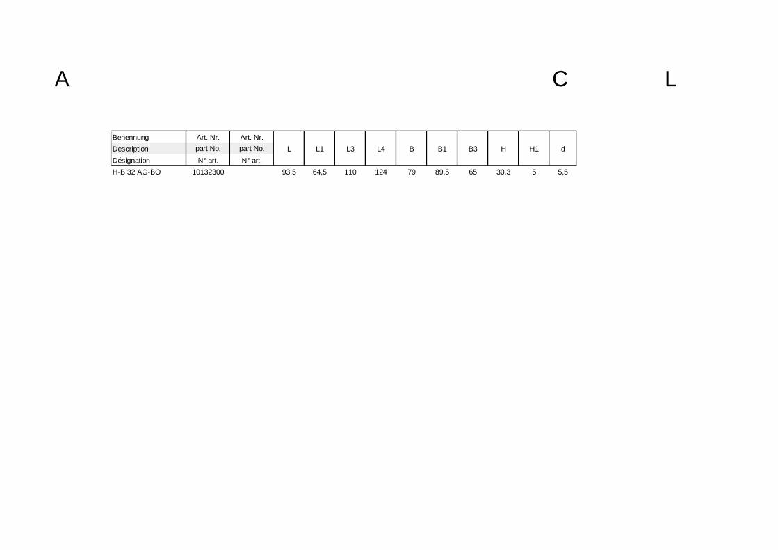
Benennung Art. Nr. Art. Nr.Description part No. part No. L L1 L3 L4 B B1 B3 H H1 dDésignation N° art. N° art.H-B 32 AG-BO 10132300 93,5 64,5 110 124 79 89,5 65 30,3 5 5,5
A CL

Headquarter
CONTACT GmbHGewerbestrasse 3070565 Stuttgart / GermanyTel. [+49] 711- 7838 03Fax [+49] 711- 7838 388Internet: www.contactconnectors.deeMail: [email protected]
Nord
-Sue
d-St
rass
e
S Industrie Strasse
Breitwiesenstraße
Schulze-Delitzsch-Strasse
Gewerbestrasse
Handwerkerstrasse
Moehringer Landstrasse
Exit 52 a
Bus stop 80
Exit 52 a
Direction Karlsruhe
Direction Munich
DEKR
A
S
tuttg
art
Vaihi
ngen
/ M
oehr
ingen
Breitwiesenstrasse
Hand
werk
erstr
asse
Kaltenta
l
POST
Am W
allgr
aben
Vaihi
ngen
S-T
rain
statio
n
SSB
SSB
L
Schillerplatz
A8
1. By airplane
From Stuttgart airport, take theS-Bahn S2 or S3 train line to theVaihingen train station (S-BahnhofVaihingen). From the platform,follow the underground passagewayto the left (east side), approximatley200m to the bus stop (Bus 80). RideBus 80 to the DEKRA stop inVahingen industrial area. TheGewerbestrasse runs parallel to thebus line (Schulze-Delitzsch-Strasse). Walk back 100m and turnleft at the next corner. Straight aheadand on the left hand side, you willsee the Gewerbestrasse and ourcompany.
2. By public transport
From the Stuttgart central trainstation (Hauptbahnhof Stuttgart),ride the S-Bahn train linie S1, S2 orS3, leaving from the lower level trainplatform, to the Vaihingen trainstation (S-Bahnhof Vaihingen). Fromthe platform, follow the undergroundpassageway to the left (east side),approximatley 200m to the bus stop(Bus 80). Ride Bus 80 to the DEKRAstop in Vahingen industrial area. TheGewerbestrasse runs parallel to thebus line (Schulze-Delitzsch-Strasse). Walk back 100m and turnleft at the next corner. Straight aheadand on the left hand side, you willsee the Gewerbestrasse and ourcompany.
3. By automobile A8 Karlsruhe-München A8 München-KarlsruheLeave the Autobahn A8 at the exit52a Vaihingen / Möhringen. Followthe road Nord-Sued-Strasse untilyou enter the Vaihingen industrialarea . Look for the sign Möhringen.Turn left and after approximately50m, turn left again. Follow the roadpassing the DEKRA building, whichthe enters the Schulz-Delitzsch-Strasse. Follow this road until thesecond corner, then turn left.Straight ahead and on the left handside, you will see the Gewerbe-strasse and our company.
4. By automobile from Stuttgart (downtown)
From the central train station(Haupbahnhof Stuttgart) drive in thedirection of the Staatsgalerie ,turning right onto the B14 at the bigintersection. Follow this roadapproximately 3000m to theHeslach-Tunnel (2000m). At theend of the tunnel, follow the left lanein the direction of Kaltental toVaihingen (Stuttgart- Vaihingen).After reaching Schillerplatz, followthe left lane crossing the streetcartrain tracks. Onto the MoehringerLandstrasse, continue until you seethe street named Am Wallgrabenwhich runs perpendicular. Turn rightdriving over the streetcar train tracksto the fourth street runningperpendicular. Turn left onto theSchulze-Delitzsch-Strasse. At thesecound corner, turn right bringingyou to the Gewerbestrasse. On theleft hand side is our company.

CONTACT GmbHGewerbestraße 30D-70565 Stuttgart Tel.: +49 / 711 / 78 38-03Fax: +49 / 711 / 78 38-366 (D)Fax: +49 / 711 / 78 38-388 (Export) [email protected] of the LAPP GROUP U
nter
Vor
beha
lt te
chni
sche
r Ä
nder
unge
n /
We
rese
rve
the
right
s to
cha
nge
with
out
notic
e /
Sou
s re
serv
e de
mod
ifict
ions
téc
hniq
ues
999990 G0