Embed Size (px)
Citation preview
__________________________________________________________________________________________________________________________________________________________________________________________________________________________________________________________________________________________________________________________________________________________________________
CUI RO21964319 - O.R.C. TIMIS: J35/2342/20.06.2007
1
MINISAT SHALLOW SATURATION DIVING
TECHNICAL SPECIFICATION FOR SINGLE BELL SHALLOW SATURATION
DIVING SYSTEM
__________________________________________________________________________________________________________________________________________________________________________________________________________________________________________________________________________________________________________________________________________________________________________
CUI RO21964319 - O.R.C. TIMIS: J35/2342/20.06.2007
2
TABLE OF CONTENTS
MINISAT SHALLOW SATURATION DIVING . . . . . . . . . . . . . . . . . . . . . . . . . . . . . . . . . . . . . . . . . . . . . . . . . . . 1
INTRODUCTION ... . . . . . . . . . . . . . . . . . . . . . . . . . . . . . . . . . . . . . . . . . . . . . . . . . . . . . . . . . . . . . . . . . . . . . . 3
Overview............................................................................................................................................... 3
Key Features ......................................................................................................................................... 5
Proven Design and Build ....................................................................................................................... 5
DESCRIPTION ... . . . . . . . . . . . . . . . . . . . . . . . . . . . . . . . . . . . . . . . . . . . . . . . . . . . . . . . . . . . . . . . . . . . . . . . . . 7
Six Man Hyperbaric Rescue/Living Chamber ........................................................................................ 8
Launching Platform .............................................................................................................................. 9
Launch and Recovery System ............................................................................................................. 10
Two Man Submersible Diving Bell (SDC) ............................................................................................ 11
Transfer Under Pressure (TUP) ........................................................................................................... 12
Sat Room ............................................................................................................................................ 12
HRC & TUP Saturation Control Panel .................................................................................................. 13
Bell Saturation Control Console.......................................................................................................... 14
Bell Handling Control Station ............................................................................................................. 15
Diving Bell ........................................................................................................................................... 17
Hot Water Diver Unit (optional) ......................................................................................................... 17
Gas Reclaim System (optional) ........................................................................................................... 19
Life Support System ............................................................................................................................ 19
Sanitary Water System ....................................................................................................................... 21
Logistic Support Software (Option) .................................................................................................... 22
Logistic Support Spares (Option) ........................................................................................................ 22
Basic Vessel Interface ......................................................................................................................... 23
P.B.S………………………………………………………………………………………………. .23
__________________________________________________________________________________________________________________________________________________________________________________________________________________________________________________________________________________________________________________________________________________________________________
CUI RO21964319 - O.R.C. TIMIS: J35/2342/20.06.2007
3
INTRODUCTION
Overview
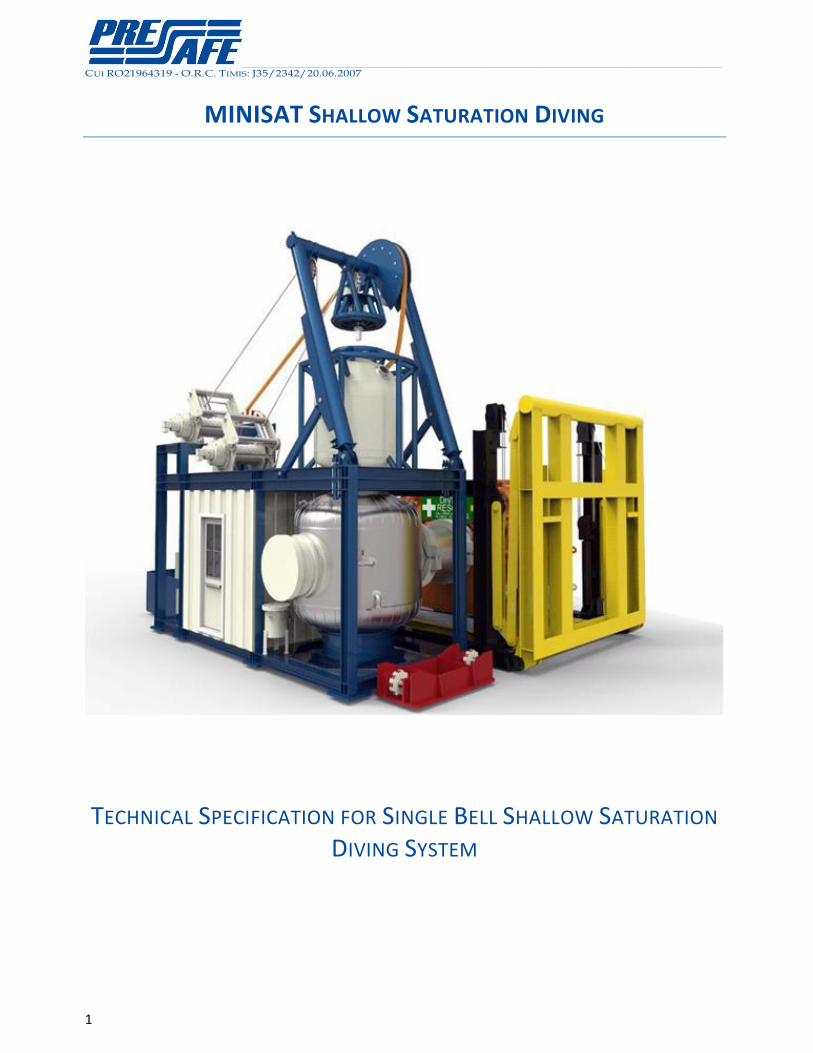
This specification together with the related attachment defines the various options available for a
MINISAT Saturation Diving System equipped with Single Bell.
Whenever different options / configuration are highlighted, the proposed choice is marked in bold
red, while the secondary proposed choices are marked in bold blue.
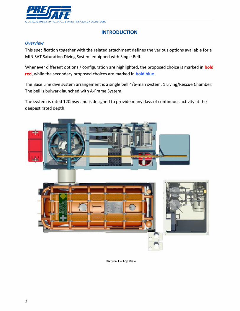
The Base Line dive system arrangement is a single bell 4/6-man system, 1 Living/Rescue Chamber.
The bell is bulwark launched with A-Frame System.
The system is rated 120msw and is designed to provide many days of continuous activity at the
deepest rated depth.
Picture 1 – Top View
__________________________________________________________________________________________________________________________________________________________________________________________________________________________________________________________________________________________________________________________________________________________________________
CUI RO21964319 - O.R.C. TIMIS: J35/2342/20.06.2007
4
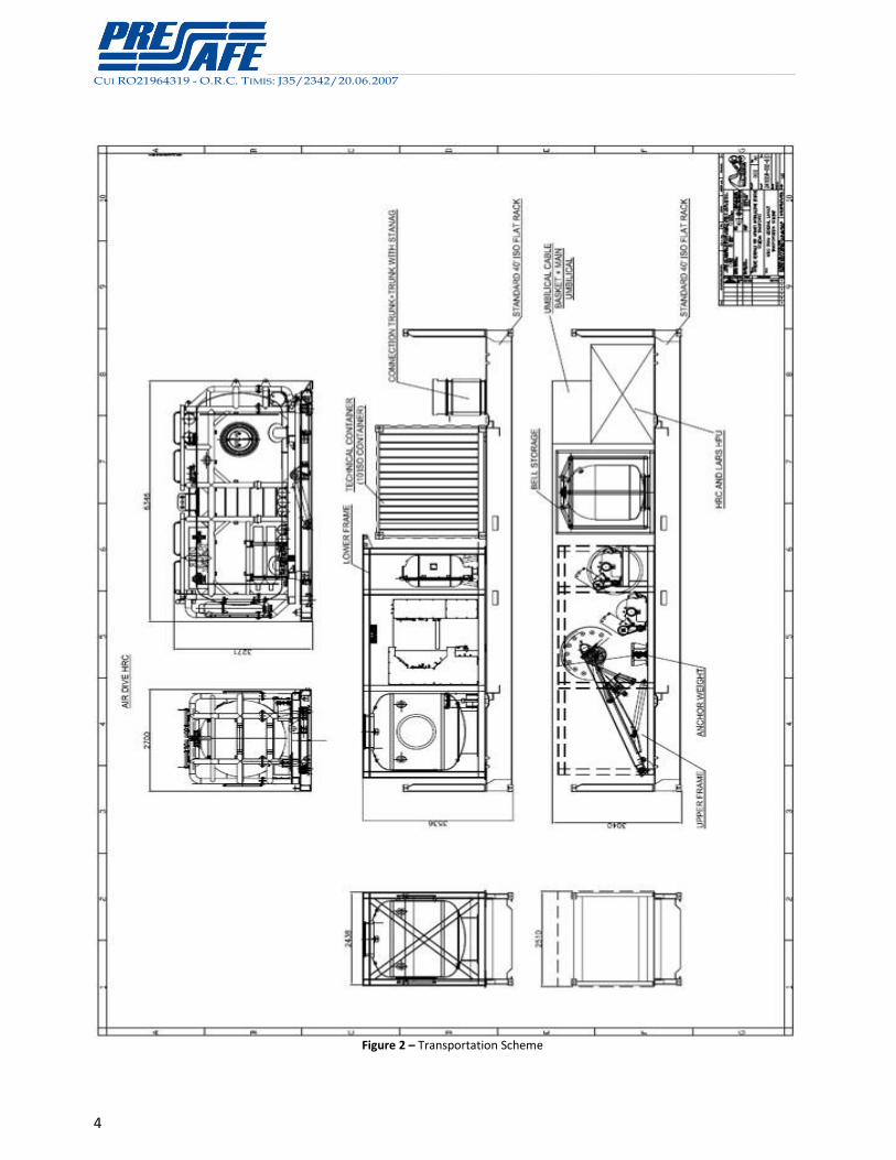
Figure 2 – Transportation Scheme
__________________________________________________________________________________________________________________________________________________________________________________________________________________________________________________________________________________________________________________________________________________________________________
CUI RO21964319 - O.R.C. TIMIS: J35/2342/20.06.2007
5
Key Features
This specification includes standard key features.
In addition to the above Pressafe describes additional or alternative requirements, which are
highlighted in tables of options, or described by a foot note. For such items a separate technical
description and quotation is available on demand.
Proven Design and Build
The Dive System is aimed for serial production, consisting of a pre-approved design and of pre
approved diving equipment.
This feature has been developed with the intent of:
minimizing the prototyping and redesign thus lowering the nonrecurring costs
granting a consolidated integration with the vessel design
allowing the development of a complete and exhaustive set of technical documentation
allowing the development of a complete life cycle service for the equipment, including
updates and improvements to the delivered configuration
Pressafe MINISAT is provided with a Class Certification for the installation on a standard Offshore
Supply Vessel. This achievement is a significant simplification in the Class approval process.
The typology of the requested certificates for the main equipment is provided in Annex B – of the
Standard Diving Contract.
The copies of the existing certificates obtained for each diving equipment is provided in Annex B –
of the Standard Diving Contract.
The available documentation includes a complete Installation, Commissioning and Sea Trials
Procedure, fully executed under Class Verification.
Pressafe MINISAT can be successfully audited in terms of IMCA compliance.
Pressafe MINISAT are provided with the system FMEA (Failure Mode Effect Analysis).
__________________________________________________________________________________________________________________________________________________________________________________________________________________________________________________________________________________________________________________________________________________________________________
CUI RO21964319 - O.R.C. TIMIS: J35/2342/20.06.2007
6
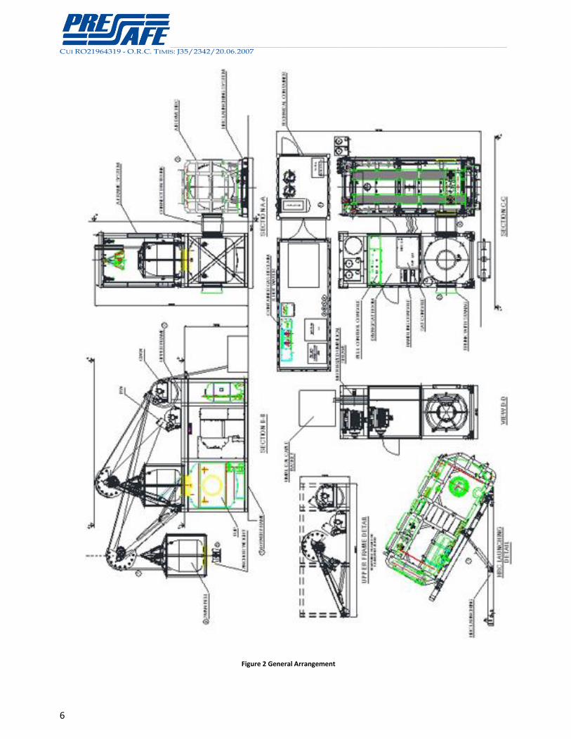
Figure 2 General Arrangement

__________________________________________________________________________________________________________________________________________________________________________________________________________________________________________________________________________________________________________________________________________________________________________
CUI RO21964319 - O.R.C. TIMIS: J35/2342/20.06.2007
7
Front View
Left View Right View
Back View
__________________________________________________________________________________________________________________________________________________________________________________________________________________________________________________________________________________________________________________________________________________________________________
CUI RO21964319 - O.R.C. TIMIS: J35/2342/20.06.2007
8
DESCRIPTION
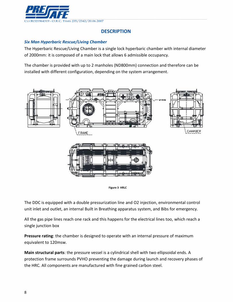
Six Man Hyperbaric Rescue/Living Chamber
The Hyperbaric Rescue/Living Chamber is a single lock hyperbaric chamber with internal diameter
of 2000mm: it is composed of a main lock that allows 6 admissible occupancy.
The chamber is provided with up to 2 manholes (ND800mm) connection and therefore can be
installed with different configuration, depending on the system arrangement.
Figure 3 HRLC
The DDC is equipped with a double pressurization line and O2 injection, environmental control
unit inlet and outlet, an internal Built in Breathing apparatus system, and Bibs for emergency.
All the gas pipe lines reach one rack and this happens for the electrical lines too, which reach a
single junction box
Pressure rating: the chamber is designed to operate with an internal pressure of maximum
equivalent to 120msw.
Main structural parts: the pressure vessel is a cylindrical shell with two ellipsoidal ends. A
protection frame surrounds PVHO preventing the damage during launch and recovery phases of
the HRC. All components are manufactured with fine grained carbon steel.
__________________________________________________________________________________________________________________________________________________________________________________________________________________________________________________________________________________________________________________________________________________________________________
CUI RO21964319 - O.R.C. TIMIS: J35/2342/20.06.2007
9
Medical lock: The chamber is equipped with a food lock sized to introduce soda reload for
emergency CO2 scrubber.
All weights are carefully designed to obtain a specific reserve of buoyancy. The unit is provided
with an available reserve of drinking water.
In case of abandonment of the ship a fast modification kit is available to transform the bunk in
secure chair for launching equipped with seat belts. This kit gives the best protection to evacuees
during launch and recovery. The chamber is provided with a single point of lifting.
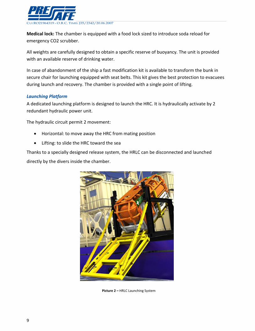
Launching Platform
A dedicated launching platform is designed to launch the HRC. It is hydraulically activate by 2
redundant hydraulic power unit.
The hydraulic circuit permit 2 movement:
Horizontal: to move away the HRC from mating position
Lifting: to slide the HRC toward the sea
Thanks to a specially designed release system, the HRLC can be disconnected and launched
directly by the divers inside the chamber.
Picture 2 – HRLC Launching System
__________________________________________________________________________________________________________________________________________________________________________________________________________________________________________________________________________________________________________________________________________________________________________
CUI RO21964319 - O.R.C. TIMIS: J35/2342/20.06.2007
10
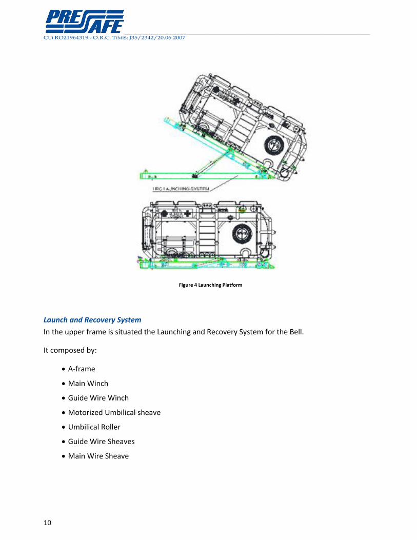
Figure 4 Launching Platform
Launch and Recovery System
In the upper frame is situated the Launching and Recovery System for the Bell.
It composed by:
A-frame
Main Winch
Guide Wire Winch
Motorized Umbilical sheave
Umbilical Roller
Guide Wire Sheaves
Main Wire Sheave
__________________________________________________________________________________________________________________________________________________________________________________________________________________________________________________________________________________________________________________________________________________________________________
CUI RO21964319 - O.R.C. TIMIS: J35/2342/20.06.2007
11
The Launch and Recovery System (LARS) is designed for bulwark launching of the diving bell. The
LARS is a reliable and proved fully hydraulic design, provided of a double redundant hydraulic
power pack. Diving operation is approved for limit of operation exceeding of 2m significant wave,
conditioned by the vessel motion parameters.
The LARS is controlled by PLC which provides all the security in order to avoid errors by operator.
The Launch and Recovery is operated from the LARS PLC Console and from the local control of the
winches.
The design of the LARS is of compact dimensions and capable to recover the complete diving bell
and anchor weight in emergency condition with the guide wire winch.
The LARS design is based on an A-Frame guided by a couple of hydraulic rams. The A - Frame is
designed in such way that the hydraulic circuit operates as hydraulic absorber to compensate the
acceleration due to the motion parameters of the vessel.
Two Man Submersible Diving Bell (SDC)
The Pressafe Diving Bell is a 2-man bottom mating bell. Design pressure 12.0 bar, man way
internal diameter 800mm.
The Diving Bells is fitted with all the accessories and components to allow full operability.
The internal diameter is 1400mm and the arrangement is designed by DG to provide the best
solution in terms of ergonomics and efficiency.
The main features are the following :
• Pressure rating: the bell is designed to operate to a depth up to 120 m.s.w. It can be used in
saturation mode with an internal pressure equivalent to the working depth, observation mode
with an internal pressure of 1 bar and a maximum working depth of 120 m.s.w.
• Main structural parts: The pressure vessel is made up of a cylindrical shell as central body
connected to one hemispherical end in the bottom and one semi spherical end in the top.
All components are manufactured with high grade fine grain carbon steel.
The external protection frame is made of structural steel pipe to protect the PV against impact.
The ring in the top part can be used as secondary main lifting point.

__________________________________________________________________________________________________________________________________________________________________________________________________________________________________________________________________________________________________________________________________________________________________________
CUI RO21964319 - O.R.C. TIMIS: J35/2342/20.06.2007
12
• Manhole: This is equipped with double acting single door with hydraulically operated locking
device complete with safety interlocking mechanism, the door is capable of withstanding inner
and outer pressure of 120 m.s.w.
• Diver umbilicals: on the seats for diver one and diver two the standard diver umbilical can be
stowed.
• Heat insulation: The bell is provided with an insulating cover on the outer surface to reduce heat
loss when bell is deployed.
• Medical lock: The bell is equipped with a stainless steel food lock that may be used during
emergency operation of the bell on the deck.
Transfer Under Pressure (TUP)
The Hyperbaric Transfer Under Pressure (TUP) is a single lock hyperbaric lock with internal
diameter of 2000mm. It’s used to reach the bell from the chamber and as toilet lock.
The lock is provided with up to 3 manholes (ND800mm) connection.
Pressure rating: the chamber is designed to operate with an internal pressure of maximum
equivalent to 120msw.
Main structural parts: the pressure vessel is a cylindrical shell with two ellipsoidal ends
Sat Room
In the lower frame is positioned the Sat Room. The room is equipped with the comfort to allow
technical oversight of the system under optimal conditions. this is the hearth of the control and
contains:
HRC & TUP Saturation Control Panel
Bell Saturation Control Console
Bell Handling Control Station
__________________________________________________________________________________________________________________________________________________________________________________________________________________________________________________________________________________________________________________________________________________________________________
CUI RO21964319 - O.R.C. TIMIS: J35/2342/20.06.2007
13
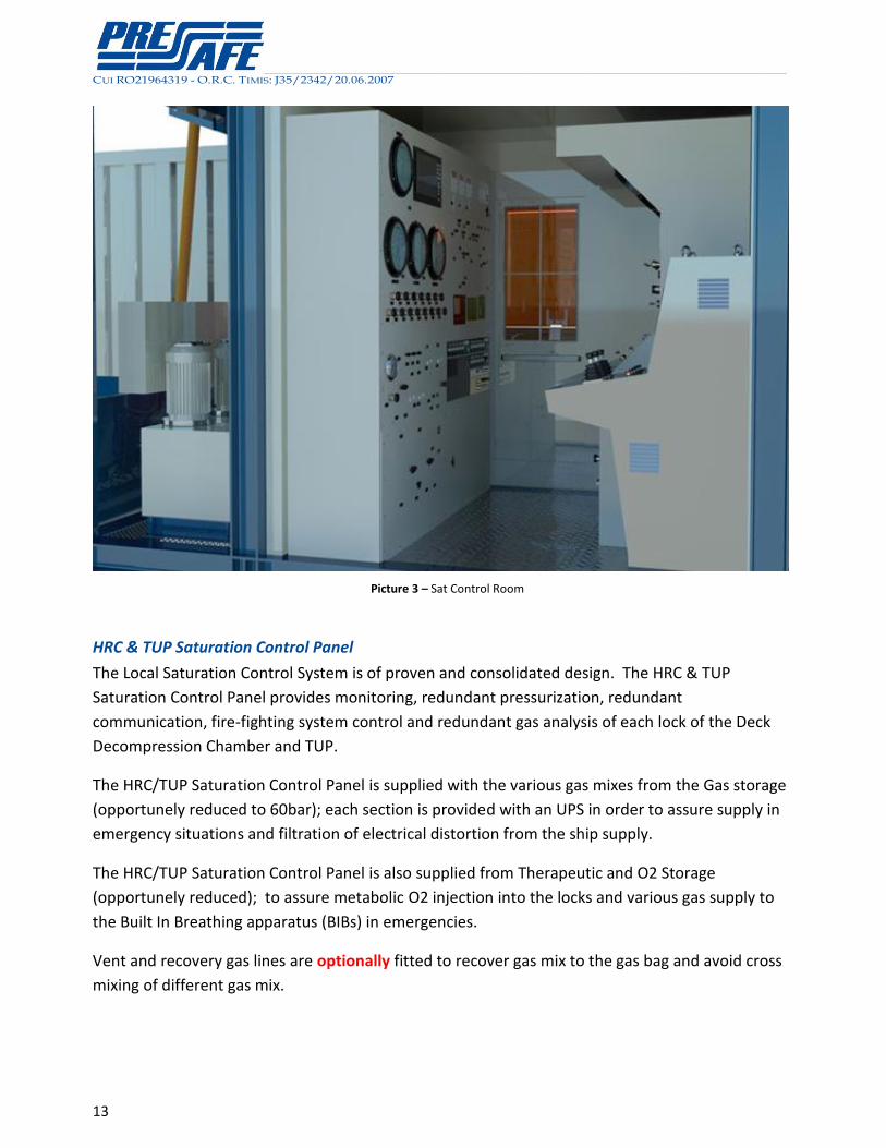
Picture 3 – Sat Control Room
HRC & TUP Saturation Control Panel
The Local Saturation Control System is of proven and consolidated design. The HRC & TUP
Saturation Control Panel provides monitoring, redundant pressurization, redundant
communication, fire-fighting system control and redundant gas analysis of each lock of the Deck
Decompression Chamber and TUP.
The HRC/TUP Saturation Control Panel is supplied with the various gas mixes from the Gas storage
(opportunely reduced to 60bar); each section is provided with an UPS in order to assure supply in
emergency situations and filtration of electrical distortion from the ship supply.
The HRC/TUP Saturation Control Panel is also supplied from Therapeutic and O2 Storage
(opportunely reduced); to assure metabolic O2 injection into the locks and various gas supply to
the Built In Breathing apparatus (BIBs) in emergencies.
Vent and recovery gas lines are optionally fitted to recover gas mix to the gas bag and avoid cross
mixing of different gas mix.
__________________________________________________________________________________________________________________________________________________________________________________________________________________________________________________________________________________________________________________________________________________________________________
CUI RO21964319 - O.R.C. TIMIS: J35/2342/20.06.2007
14
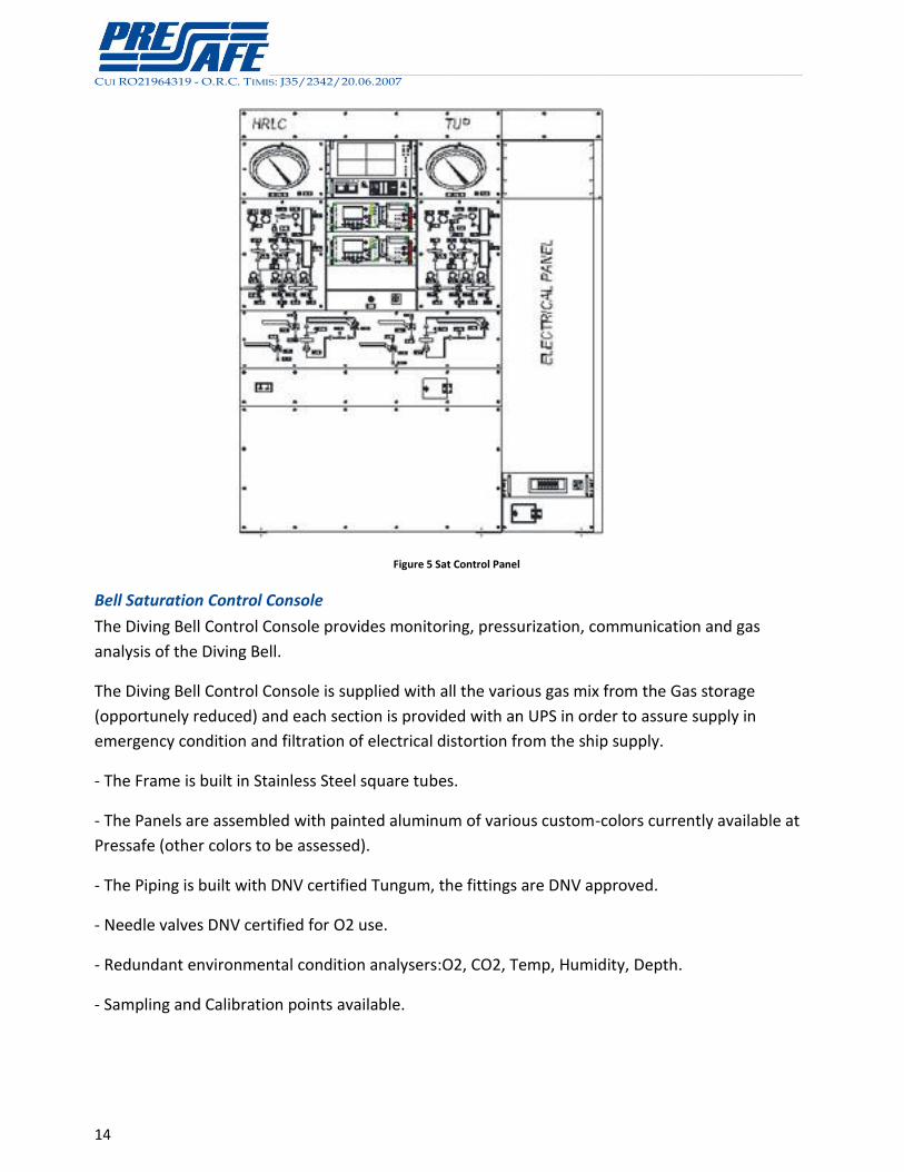
Figure 5 Sat Control Panel
Bell Saturation Control Console
The Diving Bell Control Console provides monitoring, pressurization, communication and gas
analysis of the Diving Bell.
The Diving Bell Control Console is supplied with all the various gas mix from the Gas storage
(opportunely reduced) and each section is provided with an UPS in order to assure supply in
emergency condition and filtration of electrical distortion from the ship supply.
- The Frame is built in Stainless Steel square tubes.
- The Panels are assembled with painted aluminum of various custom-colors currently available at
Pressafe (other colors to be assessed).
- The Piping is built with DNV certified Tungum, the fittings are DNV approved.
- Needle valves DNV certified for O2 use.
- Redundant environmental condition analysers:O2, CO2, Temp, Humidity, Depth.
- Sampling and Calibration points available.
__________________________________________________________________________________________________________________________________________________________________________________________________________________________________________________________________________________________________________________________________________________________________________
CUI RO21964319 - O.R.C. TIMIS: J35/2342/20.06.2007
15
- The mimic is engraved into the aluminum and painted in different colors according to the
circuits. A palette of colors and styles for mimics is available.
Bell Handling Control Station
The Bell Handling Control Station provides the interface for winches operation.
The main feature of the system is the automatic operation of the handling system, for bell
deployment and recovery, plus connection to the TUP.
In addition the Console provides the full supervision of the system status alarms and the interface
with the Hydraulic Power Packs.
The Handling Console is equipped with PLC and of an UPS to maintain the console in full
functionality in case of electrical power failure.
Communication Module
The Diving System is provided with the following communications tools, which are managed from
the Saturation Room:
Voice Communication for the inner area: complete inner area communication system, including
unscrambling devices
Voice Communication for the diving outer area: Complete communication system serving all the
remote units connecting the working sites and positions of the diving outer area (diving hangar,
decks, rooms, stores) (optional)
Accessories
The room is equipped with air conditioner, O2 sensor
Fire Fighting and Detection
The Diving Inner Area is provided with fire detection and fighting system.
The Fire Detection System consists of a set of DNV Certified Hyperbaric Flame Sensors installed in
adequate number in each DDC lock. Such detectors are connected with the Inner Area Fire
Fighting System. The activation is trigged by the operator.
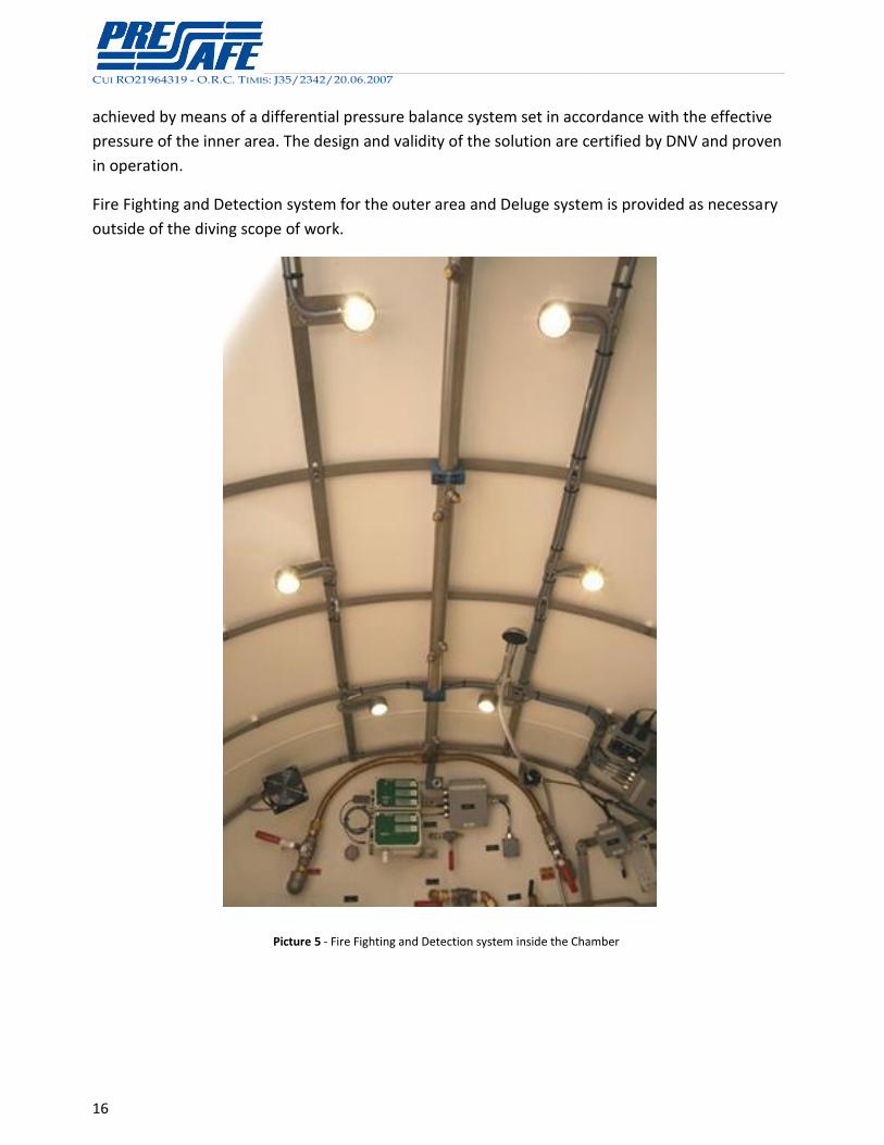
The Fire Fighting System consists of a DNV Certified water fog system installed in the inner area.
The design of the system ensures that the differential pressure of the water jet in the nozzles in
the inner area will equals the ideal design pressure requested to optimize the water mist. This is
__________________________________________________________________________________________________________________________________________________________________________________________________________________________________________________________________________________________________________________________________________________________________________
CUI RO21964319 - O.R.C. TIMIS: J35/2342/20.06.2007
16
achieved by means of a differential pressure balance system set in accordance with the effective
pressure of the inner area. The design and validity of the solution are certified by DNV and proven
in operation.
Fire Fighting and Detection system for the outer area and Deluge system is provided as necessary
outside of the diving scope of work.
Picture 5 - Fire Fighting and Detection system inside the Chamber
__________________________________________________________________________________________________________________________________________________________________________________________________________________________________________________________________________________________________________________________________________________________________________
CUI RO21964319 - O.R.C. TIMIS: J35/2342/20.06.2007
17
Diving Bell
The diving bell is bulwark launched. Due to the single bell configuration the diving bell is positively
buoyant in emergency by means of releasable ballast, to ensure a safe and proper tertiary mean
of recovery.
The positively buoyant bell is necessary to avoid the permanent constraint of an operational
working ROV capable to recover the bell from the sea bottom and to reconnect if to the vessel
crane wire.
The main features are the following :
Pressure rating : the Bell is designed to operate to a depth of up to 120 m.s.w. It can be used in
saturation mode with an internal pressure equivalent to the working depth, or in observation
mode with an internal pressure of 1 bar and a maximum working depth of 120 m.s.w.
Main structural parts : The pressure vessel is made up of a cylindrical shell as central body
connected to one hemispherical end in the bottom and one semi spherical end in the top. The
external protection frame is made of structural steel pipe to protect the PV against impact and
allow insertion into the Bell Cursor during the movement through the moon pool guides. The ring
in the top part can be used as a secondary main lifting point.
Manhole : It is equipped with double acting single door with hydraulically operated locking device
complete with safety interlocking mechanism. The door is capable of withstanding inner and outer
pressure of 120 m.s.w.
Diver Umbilicals: on the seat for diver one 35m of standard diver umbilical can be stowed.
Outside the bell on the external frame it is possible to stow up to 40m of tender diver umbilical
cable. An increase of up to 60m diver umbilical is available as an option.
Heat insulation : The bell is provided with an insulating cover on the outer surface to reduce the
heat loss when bell is deployed.
Medical lock : The bell is equipped with a stainless steel food lock that may be used during
emergency operation of the bell on deck.
Hot Water Diver Unit (optional)
The Hot Water Diver Units grant all the necessary redundancy to the Divers and all the water flow
and temperature necessary in accordance to the DNV Rules.
__________________________________________________________________________________________________________________________________________________________________________________________________________________________________________________________________________________________________________________________________________________________________________
CUI RO21964319 - O.R.C. TIMIS: J35/2342/20.06.2007
18
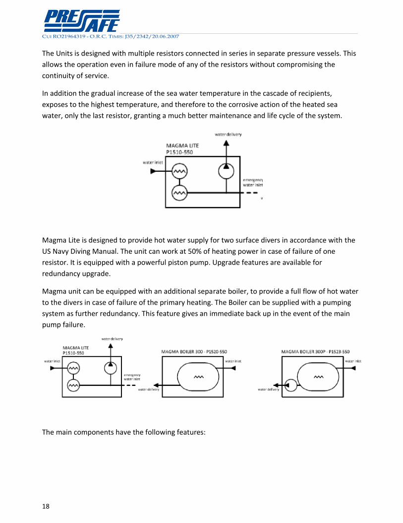
The Units is designed with multiple resistors connected in series in separate pressure vessels. This
allows the operation even in failure mode of any of the resistors without compromising the
continuity of service.
In addition the gradual increase of the sea water temperature in the cascade of recipients,
exposes to the highest temperature, and therefore to the corrosive action of the heated sea
water, only the last resistor, granting a much better maintenance and life cycle of the system.
Magma Lite is designed to provide hot water supply for two surface divers in accordance with the
US Navy Diving Manual. The unit can work at 50% of heating power in case of failure of one
resistor. It is equipped with a powerful piston pump. Upgrade features are available for
redundancy upgrade.
Magma unit can be equipped with an additional separate boiler, to provide a full flow of hot water
to the divers in case of failure of the primary heating. The Boiler can be supplied with a pumping
system as further redundancy. This feature gives an immediate back up in the event of the main
pump failure.
The main components have the following features:
__________________________________________________________________________________________________________________________________________________________________________________________________________________________________________________________________________________________________________________________________________________________________________
CUI RO21964319 - O.R.C. TIMIS: J35/2342/20.06.2007
19
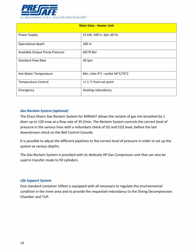
Main Data - Heater Unit
Power Supply 15 kW, 440 V, 3ph, 60 Hz
Operational depth 300 m
Available Output Pump Pressure 60/70 Bar
Standard Flow Rate 30 lpm
Hot Water Temperature Min. inlet 4°C –outlet 44°C/74°C
Temperature Control +/-1 °C from set point
Emergency Heating redundancy.
Gas Reclaim System (optional)
The Drass Divers Gas Reclaim System for MINISAT allows the reclaim of gas mix breathed by 1
diver up to 120 msw at a flow rate of 35 l/min. The Reclaim System controls the correct level of
pressure in the various lines with a redundant check of O2 and CO2 level, before the last
downstream check on the Bell Control Console.
It is possible to adjust the different pipelines to the correct level of pressure in order to set up the
system at various depths.
The Gas Reclaim System is provided with its dedicate HP Gas Compressor unit that can also be
used in transfer mode to fill cylinders.
Life Support System
One standard container 10feet is equipped with all necessary to regulate the environmental
condition in the inner area and to provide the requested redundancy to the Diving Decompression
Chamber and TUP.
__________________________________________________________________________________________________________________________________________________________________________________________________________________________________________________________________________________________________________________________________________________________________________
CUI RO21964319 - O.R.C. TIMIS: J35/2342/20.06.2007
20
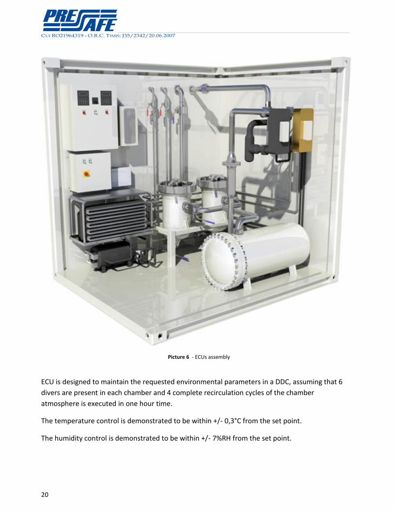
Picture 6 - ECUs assembly
ECU is designed to maintain the requested environmental parameters in a DDC, assuming that 6
divers are present in each chamber and 4 complete recirculation cycles of the chamber
atmosphere is executed in one hour time.
The temperature control is demonstrated to be within +/- 0,3°C from the set point.
The humidity control is demonstrated to be within +/- 7%RH from the set point.
__________________________________________________________________________________________________________________________________________________________________________________________________________________________________________________________________________________________________________________________________________________________________________
CUI RO21964319 - O.R.C. TIMIS: J35/2342/20.06.2007
21
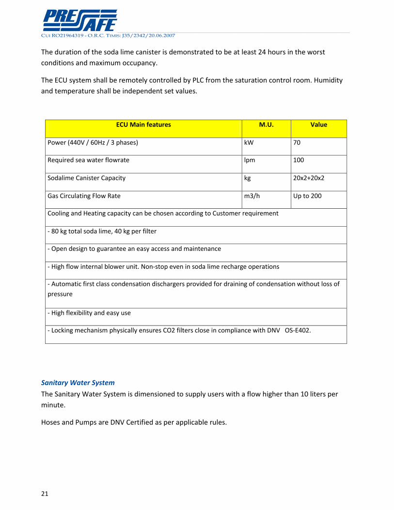
The duration of the soda lime canister is demonstrated to be at least 24 hours in the worst
conditions and maximum occupancy.
The ECU system shall be remotely controlled by PLC from the saturation control room. Humidity
and temperature shall be independent set values.
ECU Main features M.U. Value
Power (440V / 60Hz / 3 phases) kW 70
Required sea water flowrate lpm 100
Sodalime Canister Capacity kg 20x2+20x2
Gas Circulating Flow Rate m3/h Up to 200
Cooling and Heating capacity can be chosen according to Customer requirement
- 80 kg total soda lime, 40 kg per filter
- Open design to guarantee an easy access and maintenance
- High flow internal blower unit. Non-stop even in soda lime recharge operations
- Automatic first class condensation dischargers provided for draining of condensation without loss of
pressure
- High flexibility and easy use
- Locking mechanism physically ensures CO2 filters close in compliance with DNV OS-E402.
Sanitary Water System
The Sanitary Water System is dimensioned to supply users with a flow higher than 10 liters per
minute.
Hoses and Pumps are DNV Certified as per applicable rules.
__________________________________________________________________________________________________________________________________________________________________________________________________________________________________________________________________________________________________________________________________________________________________________
CUI RO21964319 - O.R.C. TIMIS: J35/2342/20.06.2007
22
Logistic Support Software (Option)
The Diving System shall be provided with a dedicated Integrated Logistic Support (ILS) Software
for the management of the Configuration, Documentation, Maintenance, Stores and Procurement
of Spares. The ILS Software shall be of proven and specialized design for diving.
The ILS Software shall be preloaded with the system configuration and will operate with graphical
and data base navigation.
The ILS Software shall allow remote connection and interface with the vessel requested users and
with ashore operating stations.
The ILS Software will be provided with an operating console integrated in the Monitoring System
and will allow the connection of the users through a web server for the Intranet / VPN.
The ILS Software will have no direct interface with the operation of the Diving System itself to
avoid reliability problems and assure the safest diving operation.
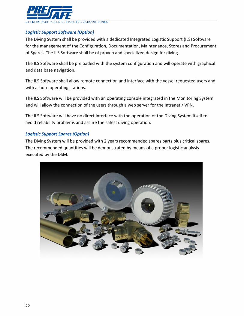
Logistic Support Spares (Option)
The Diving System will be provided with 2 years recommended spares parts plus critical spares.
The recommended quantities will be demonstrated by means of a proper logistic analysis
executed by the DSM.
__________________________________________________________________________________________________________________________________________________________________________________________________________________________________________________________________________________________________________________________________________________________________________
CUI RO21964319 - O.R.C. TIMIS: J35/2342/20.06.2007
23
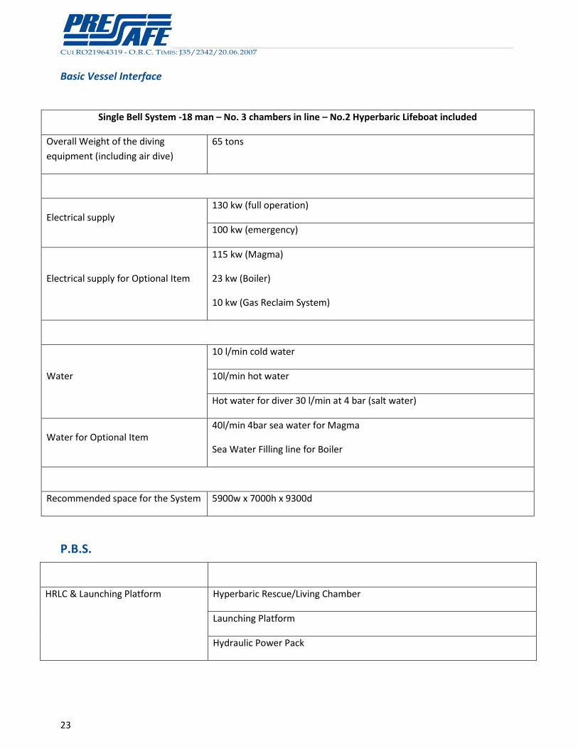
Basic Vessel Interface
Single Bell System -18 man – No. 3 chambers in line – No.2 Hyperbaric Lifeboat included
Overall Weight of the diving
equipment (including air dive)
65 tons
Electrical supply 130 kw (full operation)
100 kw (emergency)
Electrical supply for Optional Item
115 kw (Magma)
23 kw (Boiler)
10 kw (Gas Reclaim System)
Water
10 l/min cold water
10l/min hot water
Hot water for diver 30 l/min at 4 bar (salt water)
Water for Optional Item 40l/min 4bar sea water for Magma
Sea Water Filling line for Boiler
Recommended space for the System 5900w x 7000h x 9300d
P.B.S.
HRLC & Launching Platform Hyperbaric Rescue/Living Chamber
Launching Platform
Hydraulic Power Pack
__________________________________________________________________________________________________________________________________________________________________________________________________________________________________________________________________________________________________________________________________________________________________________
CUI RO21964319 - O.R.C. TIMIS: J35/2342/20.06.2007
24
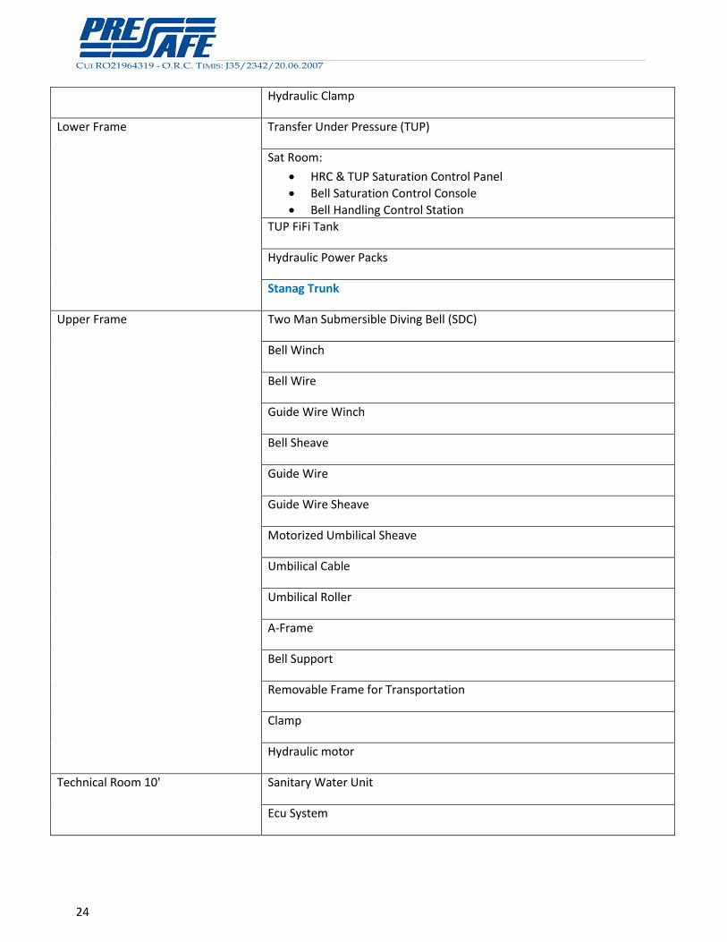
Hydraulic Clamp
Lower Frame Transfer Under Pressure (TUP)
Sat Room:
HRC & TUP Saturation Control Panel
Bell Saturation Control Console
Bell Handling Control Station
TUP FiFi Tank
Hydraulic Power Packs
Stanag Trunk
Upper Frame Two Man Submersible Diving Bell (SDC)
Bell Winch
Bell Wire
Guide Wire Winch
Bell Sheave
Guide Wire
Guide Wire Sheave
Motorized Umbilical Sheave
Umbilical Cable
Umbilical Roller
A-Frame
Bell Support
Removable Frame for Transportation
Clamp
Hydraulic motor
Technical Room 10' Sanitary Water Unit
Ecu System
__________________________________________________________________________________________________________________________________________________________________________________________________________________________________________________________________________________________________________________________________________________________________________
CUI RO21964319 - O.R.C. TIMIS: J35/2342/20.06.2007
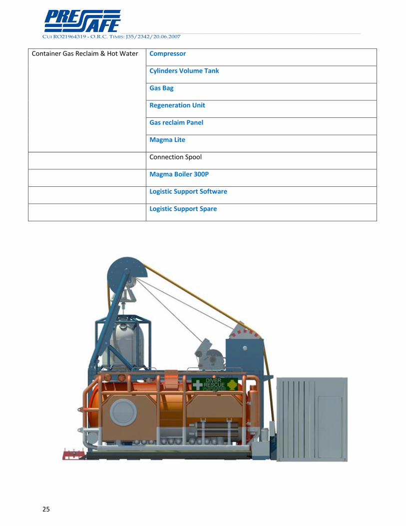
25
Container Gas Reclaim & Hot Water Compressor
Cylinders Volume Tank
Gas Bag
Regeneration Unit
Gas reclaim Panel
Magma Lite
Connection Spool
Magma Boiler 300P
Logistic Support Software
Logistic Support Spare


![hernia of the umbilical cord [وضع التوافق] of the umbilical cord.pdf · Umbilical cord hernia…cont Conclusion: ¾Hernia of the umbilical cord is a rare entityy, of the](https://img.pdfslide.net/doc/110x75/5ea7ce695a148409cd011fd0/hernia-of-the-umbilical-cord-of-the-umbilical-cordpdf.jpg)