Embed Size (px)
Citation preview

c-pro 3 nano
Programmable controllers (up to 25 I/O)
Hardware Manual | ENGLISH
Code 114CP3NE104
TheInnovationEvolution

EVCO S.p.A. c-pro 3 nano | Hardware Manual ver. 1.0 | Code 114CP3NE104
page 2 of 26
IMPORTANT
Read this document carefully before installation and before using
the device and take all the prescribed precautions. Keep this
document with the device for future consultation.
Only use the device in the ways described in this document.

EVCO S.p.A. c-pro 3 nano | Hardware Manual ver. 1.0 | Code 114CP3NE104
page 3 of 26
Index
1 INTRODUCTION ............................................................................ 5
1.1 Initial information..................................................................... 5
1.2 Main features of the models available and purchasing codes .......... 6
2 DESCRIPTION ............................................................................... 7
3 MEASUREMENTS AND INSTALLATION .............................................. 7
3.1 Measurements ......................................................................... 7
3.2 Installation .............................................................................. 7
4 ELECTRICAL CONNECTION ............................................................. 8
4.1 Connectors .............................................................................. 8
4.2 Connection to the power supply ................................................. 9
4.3 Analogue input wiring diagram ................................................... 9
4.4 Digital input wiring diagram ....................................................... 9
4.5 Analogue output wiring diagram ............................................... 10
4.6 Digital output wiring diagram ................................................... 10
4.7 INTRABUS port wiring diagram ................................................ 10
4.8 RS-485 MODBUS port wiring diagram ....................................... 10
4.9 CAN port wiring diagram ......................................................... 10
4.10 USB port connection to a personal computer.............................. 11
4.11 USB flash drive connection ...................................................... 11
4.12 Fitting the termination resistor for the RS-485 MODBUS and CAN
networks ............................................................................................ 11
4.13 Polarisation of RS-485 MODBUS network ................................... 11
5 FIRST-TIME USE ......................................................................... 12
6 USER INTERFACE AND MAIN FUNCTIONS ....................................... 12
7 DEVICE CONFIGURATION ............................................................. 12
8 List of hardware parameters ......................................................... 15
9 ACCESSORIES ............................................................................ 22
9.1 0810500023 .......................................................................... 22
9.2 0810500025 .......................................................................... 22
9.3 EVIF20SUXI ........................................................................... 22
9.4 EVIF22ISX ............................................................................. 22
9.5 EVDFAN1 .............................................................................. 22
9.6 EVUSB4096M ......................................................................... 22
9.7 CJAV..................................................................................... 22
10 TECHNICAL SPECIFICATIONS ....................................................... 23

EVCO S.p.A. c-pro 3 nano | Hardware Manual ver. 1.0 | Code 114CP3NE104
page 4 of 26

EVCO S.p.A. c-pro 3 nano | Hardware Manual ver. 1.0 | Code 114CP3NE104
page 5 of 26
1 INTRODUCTION
1.1 Initial information
c-pro 3 nano is a range of extremely compact programmable controllers with
numerous inputs and outputs (up to 25) and with an enhanced memory
capacity to meet the management needs of the HVAC/R sector and OEM
companies in particular.
Both versions with a CAN port and those with their proprietary INTRABUS port
can have the number of I/O increased with the addition of expansions.
Moreover, the CAN protocol enables a c-pro 3 nano to be integrated with the
entire family of c-pro 3 series controllers and displays.
The MODBUS RTU option, used with an external interface, is always available
in both master and slave formats. c-pro 3 nano plus is supplied with an RS-
485, making possible the simultaneous presence of 2 MODBUS protocols.
The application software can be designed in a simple, intuitive and portable
way thanks to the UNI-PRO 3 integrated development environment. The USB
port, supplied as standard, makes the controller easy to program in the
development phase and in debugging and it can be updated using the most
common USB flash drives.
The stylish design and compact format, only 74x32 mm, make it the ideal
controller for panel installation. The user interface consisting of a double LED
display (4 + 4 digit), function icons and 4 capacitive touch keys, has IP65 level
protection.

EVCO S.p.A. c-pro 3 nano | Hardware Manual ver. 1.0 | Code 114CP3NE104
page 6 of 26
1.2 Main features of the models available and purchasing codes
The table below shows the main features of the models available and the purchasing codes.
MAIN FEATURES MODELS AVAILABLE AND PURCHASING CODES
c-pro 3 nano basic c-pro 3 nano CAN c-pro 3 nano plus
Power supply EPN2L EPN3L EPN2LXC EPN3LXC EPN2LXP EPN3LXP
12 VAC • • •
24 VAC/DC • • •
Analogue inputs EPN2L EPN3L EPN2LXC EPN3LXC EPN2LXP EPN3LXP
for PTC, NTC or Pt 1000 probes; can be configured
also for dry contact digital input 5 5 5 5 5 5
for NTC probes, 0-5 V ratiometric transducers, 0-10
V, 0-20 mA or 4-20 mA transducers; can be
configured also for dry contact digital input
2 2 2 2 4 4
Digital inputs EPN2L EPN3L EPN2LXC EPN3LXC EPN2LXP EPN3LXP
dry contact and for pulse trains up to 2 KHz 2 2 2 2 2 2
dry contact 1 1 1 1 3 3
Analogue outputs EPN2L EPN3L EPN2LXC EPN3LXC EPN2LXP EPN3LXP
for 0-10 V, PWM or phase cutting signal 2 2 2 2 2 2
for 0-10 V, 0-20 mA or 4-20 mA signal 2 2
Digital outputs EPN2L EPN3L EPN2LXC EPN3LXC EPN2LXP EPN3LXP
SPST electro-mechanical relay, 3 A res. @ 250 VAC 6 6 6 6 7 7
Communications ports EPN2L EPN3L EPN2LXC EPN3LXC EPN2LXP EPN3LXP
INTRABUS port (RS-485 MODBUS master/slave by
connecting the serial interface
EVIF22ISX)
1 1 1 1 1 1
RS-485 MODBUS port 1 1
CAN port 1 1 1 1
USB port 1 1 1 1 1 1
For more information see section TECHNICAL SPECIFICATIONS.

EVCO S.p.A. c-pro 3 nano | Hardware Manual ver. 1.0 | Code 114CP3NE104
page 7 of 26
2 DESCRIPTION
The picture below shows the appearance of the devices.
The table below describes each part of the devices.
PART DESCRIPTION
1 user interface
2
Micro-switch for:
- fitting the termination resistor for the RS-485 MODBUS port
- fitting the termination resistor for the CAN port
3 Micro USB connector for USB port
4 plug-in screw terminal block for digital outputs 1... 6
5 plug-in screw terminal block for digital output 7
6
Micro-Fit connector for:
- device power supply
- auxiliary power supply (12 VDC)
- analogue inputs 1... 7
- digital inputs 1... 3
- analogue outputs 1... 2
- INTRABUS port
7 Micro-Fit connector for CAN port
8
Micro-Fit connector for:
- auxiliary power supply (5 VDC)
- analogue inputs 8... 9
- digital inputs 4... 5
- analogue outputs 3... 4
- RS-485 MODBUS port
- CAN port
For more information see subsequent sections.
3 MEASUREMENTS AND INSTALLATION
3.1 Measurements
The picture below shows the measurements of the devices.
Measurements are expressed in mm (inches).
3.2 Installation
The picture below shows the installation of the devices.
To be fitted to a panel, snap-in brackets provided.
INSTALLATION PRECAUTIONS
- The thickness of the panel must be between 0.8 and 2.0 mm (1/32 and
1/16 in).
- Ensure that the working conditions are within the limits stated in the
TECHNICAL SPECIFICATIONS section.
- Do not install the device close to heat sources, equipment with a strong
magnetic field, in places subject to direct sunlight, rain, damp, excessive
dust, mechanical vibrations or shocks.
- In compliance with safety regulations, the device must be installed
properly to ensure adequate protection from contact with electrical parts.
All protective parts must be fixed in such a way as to need the aid of a tool
to remove them.

EVCO S.p.A. c-pro 3 nano | Hardware Manual ver. 1.0 | Code 114CP3NE104
page 8 of 26
4 ELECTRICAL CONNECTION
N.B.
- Do not supply further devices with the same transformer.
- Use cables of an adequate section for the current running
through them.
- To reduce any electromagnetic interference connect the power
cables as far away as possible from the signal cables and, if
necessary, connect to a RS-485 MODBUS network and/or a CAN
network by using a twisted pair.
- The device is not compatible with controllers, I/O expansions and
remote user interfaces of the c-pro series.
- For more information see section TECHNICAL SPECIFICATIONS.
4.1 Connectors
The picture below shows the c-pro 3 nano basic connectors.
The picture below shows the c-pro 3 nano CAN connectors.
The picture below shows the c-pro 3 nano plus connectors.
The tables below describe the connectors.
Connector 1
No. DESCRIPTION
1 analogue input 6 (for PTC, NTC or Pt 1000 probes; can be
configured also for dry contact digital input)
2
analogue input 1 (for NTC probes, 0-5 V, 0-10 V, 0-20 mA or 4-20
mA transducers; can be configured also for dry contact digital
input)
3 analogue input 7 (for PTC, NTC or Pt 1000 probes; can be
configured also for dry contact digital input)
4
analogue input 2 (for NTC probes, 0-5 V, 0-10 V, 0-20 mA or 4-20
mA transducers; can be configured also for dry contact digital
input)
5 digital input 1 (dry contact and for pulse trains up to 2 KHz)
6 analogue input 3 (for PTC, NTC or Pt 1000 probes; can be
configured also for dry contact digital input)
7 digital input 2 (dry contact and for pulse trains up to 2 KHz)
8 analogue input 4 (for PTC, NTC or Pt 1000 probes; can be
configured also for dry contact digital input)
9 digital input 3 (dry contact)
10 analogue input 5 (for PTC, NTC or Pt 1000 probes; can be
configured also for dry contact digital input)
11 analogue output 1 (for 0-10 V, PWM or phase cutting signal)
12 reference (GND)
13 analogue output 2 (for 0-10 V, PWM or phase cutting signal)
14 INTRABUS port data
15 auxiliary power supply (12 VDC)
16 reference (GND)
17
device power supply (12 VAC or 24 VAC/DC, according to the
model). If the device is fed by DC power, it is not necessary to take
account of the supply voltage polarity
18
device power supply (12 VAC or 24 VAC/DC, according to the
model). If the device is fed by DC power, it is not necessary to take
account of the supply voltage polarity
Connector 2
No. DESCRIPTION
1 signal + RS-485 MODBUS master/slave port
2 signal + CAN port
3 signal - RS-485 MODBUS master/slave port
4 signal - CAN port
5 ratiometric transducer power supply 0-5 V (5 VDC)
6 reference (GND)
7 analogue output 3 (for 0-10 V, 0-20 mA or 4-20 mA signal)
8 analogue output 4 (for 0-10 V, 0-20 mA or 4-20 mA signal)
9 digital input 4 (dry contact)
10 analogue input 8 (for NTC probes, 0-5 V ratiometric transducers, 0-
10 V, 0-20 mA or 4-20 mA transducers; can be configured also for

EVCO S.p.A. c-pro 3 nano | Hardware Manual ver. 1.0 | Code 114CP3NE104
page 9 of 26
dry contact digital input)
11 digital input 5 (dry contact)
12
analogue input 9 (for NTC probes, 0-5 V ratiometric transducers, 0-
10 V, 0-20 mA or 4-20 mA transducers; can be configured also for
dry contact digital input)
Connector 3
No. DESCRIPTION
1 K1, K2 and K3 digital output common contact
2 K1 digital output normally open contact (3 A res. @ 250 VAC)
3 K2 digital output normally open contact (3 A res. @ 250 VAC)
4 K3 digital output normally open contact (3 A res. @ 250 VAC)
5 K4, K5 and K6 digital output common contact
6 K4 digital output normally open contact (3 A res. @ 250 VAC)
7 K5 digital output normally open contact (3 A res. @ 250 VAC)
8 K6 digital output normally open contact (3 A res. @ 250 VAC)
Connector 4
No. DESCRIPTION
1 K7 digital output common contact
2 K7 digital output normally open contact (3 A res. @ 250 VAC)
Connector 5
USB port.
Connector 6
No. DESCRIPTION
1 reference (GND)
2 signal - CAN port
3 signal + CAN port
4.2 Connection to the power supply
The picture below shows the c-pro 3 nano plus connection to the power supply.
4.3 Analogue input wiring diagram
The picture below shows an example of c-pro 3 nano plus analogue input
connection.
4.4 Digital input wiring diagram
The picture below shows the c-pro 3 nano plus digital input connection.

EVCO S.p.A. c-pro 3 nano | Hardware Manual ver. 1.0 | Code 114CP3NE104
page 10 of 26
4.5 Analogue output wiring diagram
The picture below shows the c-pro 3 nano plus analogue output connection.
4.6 Digital output wiring diagram
The picture below shows an example of c-pro 3 nano plus digital output
connection.
4.7 INTRABUS port wiring diagram
The picture below shows an example of c-pro 3 nano plus INTRABUS port
connection.
The maximum configuration of the INTRABUS network permits 1
programmable controller, 1 I/O expansion and 1 remote user interface.
4.8 RS-485 MODBUS port wiring diagram
The picture below shows an example of c-pro 3 nano plus RS-485 MODBUS
port connection.
In the example, the c-pro 3 nano plus is the last device on the network with an
RS-485 MODBUS port.
4.9 CAN port wiring diagram
The picture below shows an example of c-pro 3 nano plus CAN port connection.
The maximum CAN network configuration permits 32 devices and it depends
on the BUS load. The BUS load depends on the baud rate and type of device
connected.
The list below gives an example of the CAN network configuration.
- 1 programmable controller
- 4 I/O expansions
- 4 remote user interfaces
- baud rate 500,000 baud.

EVCO S.p.A. c-pro 3 nano | Hardware Manual ver. 1.0 | Code 114CP3NE104
page 11 of 26
4.10 USB port connection to a personal
computer
The picture below shows the c-pro 3 nano plus USB port connection to a
personal computer.
4.11 USB flash drive connection
The picture below shows a USB flash drive connection to the c-pro 3 nano plus.
4.12 Fitting the termination resistor for
the RS-485 MODBUS and CAN
networks
To reduce any reflections on the signal transmitted along the cables connecting
the devices to a RS-485 MODBUS network and/or a CAN network it is
necessary to fit a termination resistor to the first and last device in the
network.
The picture below shows the left side of the devices.
To fit the RS-485 MODBUS network termination resistor, place micro-switch 1
in position ON. To fit the CAN network termination resistor, place micro-switch
2 in position ON.
4.13 Polarisation of RS-485 MODBUS
network
The RS-485 MODBUS network can be polarised using the UNI-PRO 3
development environment.
PRECAUTIONS FOR ELECTRICAL CONNECTION
- If using an electrical or pneumatic screwdriver, adjust the tightening
torque.
- If the device has been moved from a cold to a warm place, the humidity
may have caused condensation to form inside. Wait about an hour before
switching on the power.
- Make sure that the supply voltage, electrical frequency and power are
within the set limits. See the section TECHNICAL SPECIFICATIONS.
- Disconnect the power supply before doing any type of maintenance.
- Do not use the device as safety device.
- For repairs and for further information, contact the EVCO sales network.

EVCO S.p.A. c-pro 3 nano | Hardware Manual ver. 1.0 | Code 114CP3NE104
page 12 of 26
5 FIRST-TIME USE
Proceed as follows.
1. Install following the instructions given in the section MEASUREMENTS
AND INSTALLATION.
2. Power up the device as shown in the section Connection to the power
supply: an internal test will start up.
The test normally takes a few seconds, when it is finished the display
will switch off.
3. Configure the device as shown in the section DEVICE
CONFIGURATION.
4. Disconnect the device from the mains.
5. Make the electrical connection as shown in the section ELECTRICAL
CONNECTION without powering up the device.
6. Power up the device.
6 USER INTERFACE AND MAIN
FUNCTIONS
The picture below shows the appearance of the device user interface.
7 DEVICE CONFIGURATION
N.B.
- The use of the DOWN key as an entity in the application software
can inhibit the access to the configuration pages: it is therefore
necessary to proceed in another way (in the application software)
to the upload of the menu page 241
- The configuration can be uploaded provided that the firmware of
the devices is compatible.
- Turn off the power after changing the configuration.
To access the procedure proceed as follows.
1.
Touch the DOWN key for 6s.
The display will show
Upper line MEnu
Lower line InFo
To access the “InFO” sub-menu proceed as follows.
2.
Touch the SET key.
3.
Touch the UP or DOWN key to select a
parameter, for example the sub-menu parameter
“Pr u”.
The display will show
Upper line Pr u (parameter)
Lower line 1 (parameter value)
4.
Touch the ON/STAND-BY key a few times to
return to the main display.
To access the other sub-menus proceed as follows.
2.
Touch the UP or DOWN key to select the sub-
menu, for example the sub-menu “Pr u”.
The display will show
Upper line MEnu
Upper line PAr
3.
Touch the SET key.
4.
Touch the SET key again.
5.
Touch the UP or DOWN key to set “-19”.
6.
Touch the SET key.
7.
Touch the UP or DOWN key to select a
parameter, for example the parameter “AI 2”.
The display will show
Upper line AI 2 (parameter)
Lower line ntC (parameter value)
8.
Touch the SET key.
9.
Touch the UP or DOWN key to set the value.
10.
Touch the SET key.
11.
Touch the ON/STAND-BY key a few times to
return to the main display.
EVCO S.p.A. c-pro 3 nano | Hardware Manual ver. 1.0 | Code 114CP3NE104
page 13 of 26
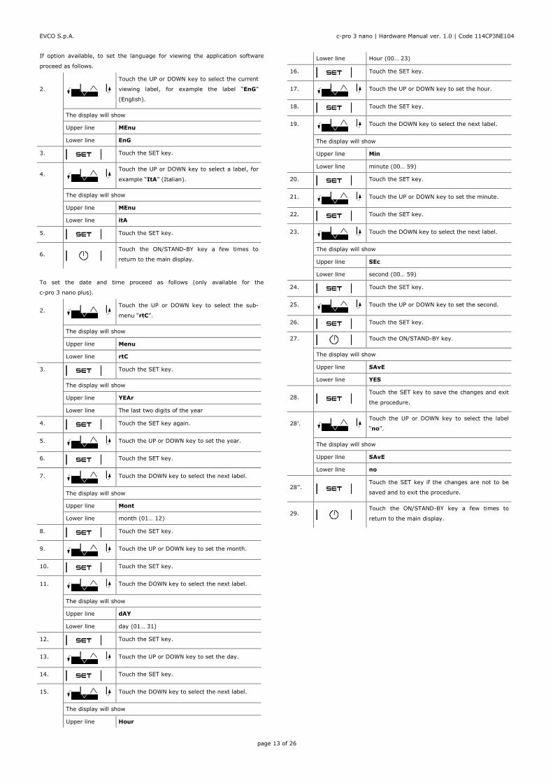
If option available, to set the language for viewing the application software
proceed as follows.
2.
Touch the UP or DOWN key to select the current
viewing label, for example the label “EnG”
(English).
The display will show
Upper line MEnu
Lower line EnG
3.
Touch the SET key.
4.
Touch the UP or DOWN key to select a label, for
example “ItA” (Italian).
The display will show
Upper line MEnu
Lower line itA
5.
Touch the SET key.
6.
Touch the ON/STAND-BY key a few times to
return to the main display.
To set the date and time proceed as follows (only available for the
c-pro 3 nano plus).
2.
Touch the UP or DOWN key to select the sub-
menu “rtC”.
The display will show
Upper line Menu
Lower line rtC
3.
Touch the SET key.
The display will show
Upper line YEAr
Lower line The last two digits of the year
4.
Touch the SET key again.
5.
Touch the UP or DOWN key to set the year.
6.
Touch the SET key.
7.
Touch the DOWN key to select the next label.
The display will show
Upper line Mont
Lower line month (01… 12)
8.
Touch the SET key.
9.
Touch the UP or DOWN key to set the month.
10.
Touch the SET key.
11.
Touch the DOWN key to select the next label.
The display will show
Upper line dAY
Lower line day (01… 31)
12.
Touch the SET key.
13.
Touch the UP or DOWN key to set the day.
14.
Touch the SET key.
15.
Touch the DOWN key to select the next label.
The display will show
Upper line Hour
Lower line Hour (00… 23)
16.
Touch the SET key.
17.
Touch the UP or DOWN key to set the hour.
18.
Touch the SET key.
19.
Touch the DOWN key to select the next label.
The display will show
Upper line Min
Lower line minute (00… 59)
20.
Touch the SET key.
21.
Touch the UP or DOWN key to set the minute.
22.
Touch the SET key.
23.
Touch the DOWN key to select the next label.
The display will show
Upper line SEc
Lower line second (00… 59)
24.
Touch the SET key.
25.
Touch the UP or DOWN key to set the second.
26.
Touch the SET key.
27.
Touch the ON/STAND-BY key.
The display will show
Upper line SAvE
Lower line YES
28.
Touch the SET key to save the changes and exit
the procedure.
28’.
Touch the UP or DOWN key to select the label
“no”.
The display will show
Upper line SAvE
Lower line no
28’’.
Touch the SET key if the changes are not to be
saved and to exit the procedure.
29.
Touch the ON/STAND-BY key a few times to
return to the main display.

EVCO S.p.A. c-pro 3 nano | Hardware Manual ver. 1.0 | Code 114CP3NE104
page 14 of 26
To download the device configuration using a USB flash drive proceed as
follows.
1. Connect a USB flash drive to the device as shown in the section
USB flash drive connection.
2.
Touch the DOWN key for 4s.
The display will show
Upper line MEnu
Lower line InFo
3.
Touch the UP or DOWN key to select the sub-
menu “Strd”.
The display will show
Upper line Menu
Lower line Strd
4.
Touch the SET key.
5.
Touch the SET key again.
6.
Touch the UP or DOWN key to set “-19”.
7.
Touch the SET key.
The display will show
Upper line PAr (device parameters)
Lower line KEY
7’.
Touch the UP or DOWN key to select the label
“bK”.
The display will show
Upper line bK (device backup memory)
Lower line MEM
8.
Touch the SET key.
The display will show
Upper line Key (or MEM)
Lower line APPl (application software parameters)
8’.
Touch the UP or DOWN key to select the label
“HU”.
The display will show
Upper line KeY (or MEM)
Lower line HU (hardware parameters)
9.
Touch the SET key.
10.
Touch the UP or DOWN key to select “SAvE”.
The display will show
Upper line SAvE
Lower line OK
11.
Touch the SET key again.
The information will be downloaded to the USB flash drive. This
operation normally takes a few seconds. If there is an error the
system alarm LED will light up.
12. Disconnect the USB flash drive from the device.
13.
Touch the ON/STAND-BY key a few times to
return to the main display.
To upload the device configuration using a USB flash drive proceed as follows.
1. Connect a USB flash drive to the device as shown in the section
USB flash drive connection.
2.
Touch the DOWN key for 4s.
The display will show
Upper line MEnu
Lower line InFo
3.
Touch the UP or DOWN key to select the sub-
menu “Strd”.
The display will show
Upper line Menu
Lower line Strd
4.
Touch the SET key.
5.
Touch the SET key again.
6.
Touch the UP or DOWN key to set “-19”.
7.
Touch the SET key.
The display will show
Upper line PAr (device parameters)
Lower line KEY
7’.
Touch the UP or DOWN key to select the label
“bK”.
The display will show
Upper line bK (device backup memory)
Lower line MEM
8.
Touch the SET key.
9.
Touch the UP or DOWN key to select “rESt”.
The display will show
Upper line rESt
Lower line oK
10.
Touch the SET key again.
The information will be uploaded to the USB flash drive. This
operation normally takes a few seconds. If there is an error the
system alarm LED will light up.
11. Disconnect the USB flash drive from the device.
12.
Touch the ON/STAND-BY key a few times to
return to the main display.

EVCO S.p.A. c-pro 3 nano | Hardware Manual ver. 1.0 | Code 114CP3NE104
page 15 of 26
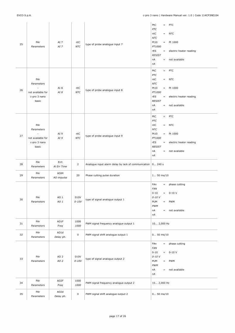
8 List of hardware parameters
The table below shows the hardware parameters of the device. The hardware parameter values are overwritten by the parameter values of the application software.
Text in italics indicates the way the labels appear on a graphic display, for example on a remote user interface.
No. SUB-MENU PARAMETER DEFAULT DESCRIPTION MIN... MAX.
1 InFo
Info
Pr n
PROJ NUM - - - - application project number read-only parameter
2 InFo
Info
Pr u
PROJ VER - - - - application project version read-only parameter
3 InFo
Info
Pr r
PROJ REV - - - - application project revision read-only parameter
4 InFo
Info
FU u
FW VER - - - - firmware version read-only parameter
5 InFo
Info
FU r
FW REV - - - - firmware revision read-only parameter
6 InFo
Info
FU S
FW UND - - - - firmware sub-revision read-only parameter
7 InFo
Info
HU u
HW VER - - - - hardware version read-only parameter
8 InFo
Info
HU r
HW REV - - - - hardware revision read-only parameter
9 InFo
Info
SPEc
SPEC - - - - type of hardware (G general; S special) read-only parameter
10 InFo
Info
SU u
SW VER - - - - UNI-PRO 3 version read-only parameter
11 InFo
Info
SU r
SW REV - - - - UNI-PRO 3 revision read-only parameter
12 InFo
Info
SU S
SW UND - - - - UNI-PRO 3 sub-version read-only parameter
13 InFo
Info
Sn
SN - - - - serial number read-only parameter
14 InFo
Info
tESt
Test - - - -
information concerning production testing and
calibration read-only parameter
15 InFo
Info
MK n
MASK N - - - -
mask number (according to the manufacturer's
coding system) read-only parameter
16 InFo
Info
MK u
MASK VER - - - -
mask version (according to the manufacturer's
coding system) read-only parameter
17 InFo
Info
MK r
MASK REV - - - -
mask revision (according to the manufacturer's
coding system) read-only parameter
18 InFo
Info
dAtE
date and time - - - -
date and time the application project was last
compiled read-only parameter
19 PAr
Parameters
AI 1
AI 1
ntC
NTC type of probe analogue input 1
ntC = NTC
NTC
0-20 = 0-20 mA
0-20mA
4-20 = 4-20 mA
4-20mA
0-5 = 0-5 V ratiometric
0-5V
0-10 = 0-10 V
0-10V
rES = electric heater reading
RESIST
nA = not available
nA

EVCO S.p.A. c-pro 3 nano | Hardware Manual ver. 1.0 | Code 114CP3NE104
page 16 of 26
20 PAr
Parameters
AI 2
AI 2
ntC
NTC type of probe analogue input 2
ntC = NTC
NTC
0-20 = 0-20 mA
0-20mA
4-20 = 4-20 mA
4-20mA
0-5 = 0-5 V ratiometric
0-5V
0-10 = 0-10 V
0-10V
rES = electric heater reading
RESIST
nA = not available
nA
21 PAr
Parameters
AI 3
AI 3
ntC
NTC type of probe analogue input 3
PtC = PTC
PTC
ntC = NTC
NTC
Pt10 = Pt 1000
PT1000
rES = electric heater reading
RESIST
nA = not available
nA
22 PAr
Parameters
AI 4
AI 4
ntC
NTC type of probe analogue input 4
PtC = PTC
PTC
ntC = NTC
NTC
Pt10 = Pt 1000
PT1000
rES = electric heater reading
RESIST
nA = not available
nA
23 PAr
Parameters
AI 5
AI 5
ntC
NTC type of probe analogue input 5
PtC = PTC
PTC
ntC = NTC
NTC
Pt10 = Pt 1000
PT1000
rES = electric heater reading
RESIST
nA = not available
nA
24 PAr
Parameters
AI 6
AI 6
ntC
NTC type of probe analogue input 6
PtC = PTC
PTC
ntC = NTC
NTC
Pt10 = Pt 1000
PT1000
rES = electric heater reading
RESIST
nA = not available
nA
EVCO S.p.A. c-pro 3 nano | Hardware Manual ver. 1.0 | Code 114CP3NE104
page 17 of 26
25 PAr
Parameters
AI 7
AI 7
ntC
NTC type of probe analogue input 7
PtC = PTC
PTC
ntC = NTC
NTC
Pt10 = Pt 1000
PT1000
rES = electric heater reading
RESIST
nA = not available
nA
26
PAr
Parameters
-
not available for
c-pro 3 nano
basic
AI 8
AI 8
ntC
NTC type of probe analogue input 8
PtC = PTC
PTC
ntC = NTC
NTC
Pt10 = Pt 1000
PT1000
rES = electric heater reading
RESIST
nA = not available
nA
27
PAr
Parameters
-
not available for
c-pro 3 nano
basic
AI 9
AI 9
ntC
NTC type of probe analogue input 9
PtC = PTC
PTC
ntC = NTC
NTC
Pt10 = Pt 1000
PT1000
rES = electric heater reading
RESIST
nA = not available
nA
28 PAr
Parameters
Errt
Al Err Time 2 Analogue input alarm delay by lack of communication 0... 240 s
29 PAr
Parameters
AOiM
AO impulse 20 Phase cutting pulse duration 1... 50 ms/10
30 PAr
Parameters
AO 1
AO 1
010V
0-10V type of signal analogue output 1
FAn = phase cutting
FAN
0-10 = 0-10 V
0-10 V
PUM = PWM
PWM
nA = not available
nA
31 PAr
Parameters
AO1F
Freq
1000
1000 PWM signal frequency analogue output 1 10... 2,000 Hz
32 PAr
Parameters
AO1d
Delay ph. 0 PWM signal shift analogue output 1 0... 50 ms/10
33 PAr
Parameters
AO 2
AO 2
010V
0-10V type of signal analogue output 2
FAn = phase cutting
FAN
0-10 = 0-10 V
0-10 V
PUM = PWM
PWM
nA = not available
nA
34 PAr
Parameters
AO2F
Freq
1000
1000 PWM signal frequency analogue output 2 10... 2,000 Hz
35 PAr
Parameters
AO2d
Delay ph. 0 PWM signal shift analogue output 2 0... 50 ms/10

EVCO S.p.A. c-pro 3 nano | Hardware Manual ver. 1.0 | Code 114CP3NE104
page 18 of 26
36
PAr
Parameters
-
only available
for c-pro 3 nano
plus
AO 3
AO 3
010V
0-10V type of signal analogue output 3
0-20 = 0-20 mA
0-20mA
4-20 = 4-20 mA
4-20mA
0-10 = 0-10 V
0-10V
37
PAr
Parameters
-
only available
for c-pro 3 nano
plus
AO 4
AO 4
010V
0-10V type of signal analogue output 4
0-20 = 0-20 mA
0-20mA
4-20 = 4-20 mA
4-20mA
0-10 = 0-10 V
0-10V
38 Par > Par2
Parameters
IOto
I/O Timeout
60
60
remote I/O disable delay by lack of CAN
communication 1... 240 s
39 Par > Par2
Parameters
EnLE
En. Prg Level
nO
NO
enable access to the first level page by touching a
key
yES YES = proceed as follows.
- touch the SET key for 3 seconds to
access the first page of level 1
- touch the SET key for 3 seconds to
access the first page of level 2
- touch the SET key for 3 seconds to
access the first page of level 3
40 Par > Par2
Parameters
PUIn
Password Indi
nO
NO
password requirement for access to the different
levels
nO NO = access to a lower level does not require
a password
yES YES = access to each level requires a
password
41
nEt > CAn
Networks > CAN
Bus
-
not available for
c-pro 3 nano
basic
nLoG
MyNode 1 device CAN address 1... 127
42
nEt > CAn
Networks > CAN
Bus
-
not available for
c-pro 3 nano
basic
MASt
Master
YES
YES enable master function in a CAN network YES YES = YES
43
nEt > CAn
Networks > CAN
Bus
-
not available for
c-pro 3 nano
basic
bAUd
Baud
20
20K baud rate in a CAN network
20 = 20,000 baud
20K
50 = 50,000 baud
50K
125 = 125,000 baud
125K
500 = 500,000 baud
500K
44
nEt > CAn
Networks > CAN
Bus
-
not available for
c-pro 3 nano
basic
tiME
Time 5
exclusion of a CAN network device delayed by lack of
communication 1... 60 s

EVCO S.p.A. c-pro 3 nano | Hardware Manual ver. 1.0 | Code 114CP3NE104
page 19 of 26
45
nEt > CAn
Networks > CAN
Bus
-
not available for
c-pro 3 nano
basic
nLoG
NetworkNode
Logic
[1] CAN network device node [1]... [32]
46
nEt > CAn
Networks > CAN
Bus
-
not available for
c-pro 3 nano
basic
NPHI
NetworkNode
Phisical
99 CAN network device address 0... 127
47
nEt > CAn > bit
tiM
Networks > CAN
Bus > Bit
Timing
-
not available for
c-pro 3 nano
basic
tSG1
TSEG1 - - - - unused - - - -
48
nEt > CAn > bit
tiM
Networks > CAN
Bus > Bit
Timing
-
not available for
c-pro 3 nano
basic
tSG2
TSEG2 - - - - unused - - - -
49
nEt > CAn > bit
tiM
Networks > CAN
Bus > Bit
Timing
-
not available for
c-pro 3 nano
basic
SJU
SJW - - - - unused - - - -
50
nEt > CAn > bit
tiM
Networks > CAN
Bus > Bit
Timing
-
not available for
c-pro 3 nano
basic
btr1
BTR(1) - - - - unused - - - -
51
nEt > CAn >
CAn dbg
Networks > CAN
Bus > Debug
-
not available for
c-pro 3 nano
basic
StAt
Status - - - - CAN communication machine status
read-only parameter
init = initialisation
INIT
StoP = stop
STOPPED
oPEr = operating
OPERAT
PrEo = pre-operating
PRE-OP

EVCO S.p.A. c-pro 3 nano | Hardware Manual ver. 1.0 | Code 114CP3NE104
page 20 of 26
52
nEt > CAn >
CAn dbg
Networks > CAN
Bus > Debug
-
not available for
c-pro 3 nano
basic
BUS
Bus Status - - - - CAN communication BUS status
read-only parameter
OH = ok
OK
UArn = warning
WARNING
PASS = receive mode only
PASSIVE
bOFF = off
BUS OFF
53
nEt > CAn >
CAn dbg
Networks > CAN
Bus > Debug
-
not available for
c-pro 3 nano
basic
rU
Cnt Rx - - - - number of packages received read-only parameter
54
nEt > CAn >
CAn dbg
Networks > CAN
Bus > Debug
-
not available for
c-pro 3 nano
basic
tU
Cnt Tx - - - - number of packages transmitted read-only parameter
55
nEt > CAn >
CAn dbg
Networks > CAN
Bus > Debug
-
not available for
c-pro 3 nano
basic
OuF
Cnt Ovf - - - - number of overflow packages read-only parameter
56
nEt > CAn >
CAn dbg
Networks > CAN
Bus > Debug
-
not available for
c-pro 3 nano
basic
PASS
Cnt Passive - - - - number of transitions with BUS in receive mode only read-only parameter
57
nEt > CAn >
CAn dbg
Networks > CAN
Bus > Debug
-
not available for
c-pro 3 nano
basic
bOFF
Cnt Bus Off - - - - number of transitions with BUS off read-only parameter
58
nEt > CAn >
CAn dbg
Networks > CAN
Bus > Debug
-
not available for
c-pro 3 nano
basic
rHEr
Cnt Rx Err - - - - number of reception errors read-only parameter

EVCO S.p.A. c-pro 3 nano | Hardware Manual ver. 1.0 | Code 114CP3NE104
page 21 of 26
59
nEt > CAn >
CAn dbg
Networks > CAN
Bus > Debug
-
not available for
c-pro 3 nano
basic
tHEr
Cnt Tx Err - - - - number of transmission errors read-only parameter
60
nEt > CAn >
CAn dbg
Networks > CAN
Bus > Debug
-
not available for
c-pro 3 nano
basic
StuF
Cnt Stuff - - - - stuff number read-only parameter
61
nEt > CAn >
CAn dbg
Networks > CAN
Bus > Debug
-
not available for
c-pro 3 nano
basic
ForM
Cnt Form - - - - form number read-only parameter
62
nEt > CAn >
CAn dbg
Networks > CAN
Bus > Debug
-
not available for
c-pro 3 nano
basic
AcK
Cnt Ack - - - - ack number read-only parameter

EVCO S.p.A. c-pro 3 nano | Hardware Manual ver. 1.0 | Code 114CP3NE104
page 22 of 26
9 ACCESSORIES
9.1 0810500023
USB extension cable
Makes it possible to connect to a personal computer.
Length: 1 m (3.28 ft).
9.2 0810500025
USB extension cable
Makes it possible to connect a USB flash drive.
Length: 2 m (6.56 ft).
9.3 EVIF20SUXI
RS-485/USB serial interface
Makes it possible to connect to the Parameters Manager setup software
system.
9.4 EVIF22ISX
INTRABUS/RS-485 serial interface
Makes it possible to convert the INTRABUS signal into an RS-485 signal.
9.5 EVDFAN1
Phase cutting speed regulator for single-phase fans
Makes it possible to regulate a single-phase fan speed with a PWM command
signal.
The maximum operating current is 5 A.
9.6 EVUSB4096M
4GB USB flash drive
Makes possible quick configuration upload and download and application
software upload.
9.7 CJAV
Connection kit
Makes cabling possible.
The table below lists the kits available.
KIT SUITABLE FOR
CJAV40 c-pro 3 nano basic
CJAV41 c-pro 3 nano CAN
CJAV42 c-pro 3 nano plus

EVCO S.p.A. c-pro 3 nano | Hardware Manual ver. 1.0 | Code 114CP3NE104
page 23 of 26
10 TECHNICAL SPECIFICATIONS
Purpose of the control device Function controller
Construction of the control device Built-in electronic device
Container Black, self-extinguishing
Category of heat and fire resistance D
Measurements 75.0 x 33.0 x 59.0 mm (2 15/16 x
1 5/16 x 2 5/16 in)
Mounting methods for the control
device
To be fitted to a panel, snap-in
brackets provided
Degree of protection provided by the
covering
IP65 (front)
Connection method
Micro-Fit connectors
Plug-in screw terminal
blocks for wires up to
2.5 mm²
Female Micro USB
connector
Maximum permitted length for connection cables
Power supply: 10 m (32.8 ft) Analogue inputs: 10 m (32.8 ft)
Auxiliary power supply and 0-5 V
ratiometric transducer power supply:
10 m (32.8 ft)
Digital inputs: 10 m (32.8 ft)
0-10 V, 0-20 mA and 4-20 mA
analogue outputs: 10 m (32.8 ft) PWM analogue outputs: 1 m (3.28 ft)
Phase cutting analogue outputs: 1 m
(3.28 ft) Digital outputs: 100 m (328 ft)
INTRABUS port: 10 m (32.8 ft) RS-485 MODBUS port: 1,000 m
(3,280 ft)
CAN port: 1,000 m (3,280 ft), baud rate: 20,000 baud
500 m (1,640 ft), baud rate: 50,000 baud
250 m (820 ft), baud rate: 125,000 baud
50 m (164 ft), baud rate: 500,000 baud
USB port: 1 m (3.28 ft)
To cable the device, we recommend using the CJAV40, CJAV41 or CJAV42
connection kit (to be ordered separately). To program it, use USB
0810500023 cable (to be ordered separately).
Operating temperature from 0 to 55 °C (from 32 to 131 °F)
Storage temperature from -20 to 70 °C (from -4 to 158 °F)
Operating humidity
Relative humidity without condensate
from 5 to 95%
Pollution status of the control device 2
Compliance:
RoHS 2011/65/EC WEEE 2012/19/EU
REACH (EC) Regulation no.
1907/2006 EMC 2014/30/EU
Power supply (according
to the model) 12 VAC
12 VAC (+10% -15%), 50/60 Hz (±3
Hz), max. 7 VA not insulated
24 VAC/DC
24 VAC (+10% -15%), 50/60 Hz (±3
Hz), max. 7 VA not insulated
24 VDC (+30% -15%), max. 5 W not
insulated
Protect the power supply with a 2 A-T 250 VAC fuse.
Earthing methods for the control
device None
Rated impulse-withstand voltage 4 KV
Over-voltage category III
Software class and structure A
Clock According to the model (with
secondary lithium battery)
Clock drift ≤ 60 s/month at 25 °C (77 °F)
Clock battery autonomy in the
absence of a power supply > 6 months at 25 °C (77 °F)
Clock battery charging time 24 h (the battery is charged by the
power supply of the device)
Analogue inputs
5 for PTC, NTC or Pt 1000 probes
(can be configured also for dry
contact digital input)
Up to 4 for NTC probes, 0-5 V, 0-10
V, 0-20 mA or 4-20 mA transducers
(can be configured also for dry
contact digital input)
PTC probes Sensor type KTY 81-121 (990 Ω @ 25 °C, 77 °F)
Measurement range from -50 to 150 °C (from -58 to 302
°F)
Resolution 0.1 °C (1 °F)
NTC
probes Sensor type ß3435 (10 KΩ @ 25 °C, 77 °F)
Measurement range from -50 to 120 °C (from -58 to 248
°F)
Resolution 0.1 °C (1 °F)
Pt 1000
probes Sensor type 1 KΩ @ 0 °C, 32 °F
Measurement range from -100 to 400 °C (from -148 to
752 °F)
Resolution 0.1 °C (1 °F)
0-5 V
transducer
s
Input resistance ≥ 10 KΩ
Resolution 0.01 V
0-10 V
transducer
s
Input resistance ≥ 10 KΩ
Resolution 0.01 V
4-20 mA
transducer
s
Input resistance ≤ 200 Ω
Resolution 0.01 mA

EVCO S.p.A. c-pro 3 nano | Hardware Manual ver. 1.0 | Code 114CP3NE104
page 24 of 26
Auxiliary power supply:
If the device has a power supply of
12 VAC, 12 VDC +10% -15%, 120
mA max.
If the device has a power supply of
24 VAC/DC, 12 VDC, 120 mA max.
Ratiometric transducer power supply 5 VDC, +10% -15%, 20 mA max.
Digital inputs
2 dry contact and for pulse trains up
to 2 KHz
Up to 3, dry contact
Dry contact Contact type 3.3 VDC, 2 mA
Power supply None
Analogue outputs 2 for 0-10 V, PWM or phase cutting
signal
On request, 2 for 0-10 V, 0-20 mA or
4-20 mA signal
0-10 V
signal
Minimum applicable
impedance 1 KΩ
Resolution 0.01 V
PWM signal Power supply 0... 10 VDC (+16% -25%), 10 mA
max.
Frequency 10 Hz... 2 KHz
Duty: 0... 100%
0-20 mA
and 4-20
mA
Input resistance 40... 300 Ω
signal Resolution 0.05 mA
Digital outputs
Up to 7 with SPST electro-mechanical
relay, 3 A res. @ 250 VAC
The device guarantees reinforced insulation between each digital output
connector and the rest of the components of the device.
Type 1 or Type 2 Actions Type 1
Additional features of Type 1 or Type
2 actions
C
Displays Double custom display, 4 + 4 digit,
with function icons
Alarm buzzer Built-in
Communications ports
1 INTRABUS port (RS-485 MODBUS
master/slave by connecting the serial
interface EVIF22ISX)
According to the model, 1 RS-485
MODBUS master/slave port
According to the model, 1 CAN port 1 USB port

EVCO S.p.A. c-pro 3 nano | Hardware Manual ver. 1.0 | Code 114CP3NE104
page 25 of 26
c-pro 3 nano
Programmable controllers (up to 25 I/O)
Hardware Manual ver. 1.0
PT - 20/16
Code 114CP3NE104
N.B.
The device must be disposed of according to local regulations
governing the collection of electrical and electronic waste.
This document and the solutions contained therein are the intellectual property
of EVCO and thus protected by the Italian Intellectual Property Rights Code
(CPI). EVCO imposes an absolute ban on the full or partial reproduction and
disclosure of the content other than with the express approval of EVCO. The
customer (manufacturer, installer or end-user) assumes all responsibility for
the configuration of the device. EVCO accepts no liability for any possible
errors in this document and reserves the right to make any changes, at any
time without prejudice to the essential functional and safety features of the
equipment.

EVCO S.p.A. c-pro 3 nano | Hardware Manual ver. 1.0 | Code 114CP3NE104
page 26 of 26
EVCO S.p.A.
Via Feltre 81, 32036 Sedico Belluno ITALY
Tel. 0437/8422 | Fax 0437/83648
[email protected] | www.evco.it