Embed Size (px)
Citation preview
1
prof. keyur parmar
CRITERIA USED FOR SAND TESTING / PROPERTIES: Moisture content, green and dry sand permeabilities, compression, tension, transverse and shear strengths, deformation during compression tests, green and dry hardness, clay content, grain-size distribution, combustible content, pressure, volume of gases evolved, flowability, sintering point, resistance to spalling etc.
Continued…….

2
prof. keyur parmar
SAND TESTING For maintaining consistent quality of moulding sand The sand or say blended sand is characterized by
Grain Size Grain Shape Surface smoothness Density Contaminants Moisture content Clay content Compactibility
Final Mould key properties are mould hardness, permeability and strength.
3
prof. keyur parmar
GENERAL TEST PERFORMED TO JUDGE THE MOULDING AND CASTING CHARACTERISTIC ARE: Moisture Content Test Clay content Test Chemical Composition of sand Grain Shape and surface texture of sand Grain Size distribution of sand Specific Surface of sand grains. Water absorption capacity of sand Refractoriness of sand Strength Test Permeability Test Flowability Test Shatter Index Test Mould Harness Test.

4
prof. keyur parmar
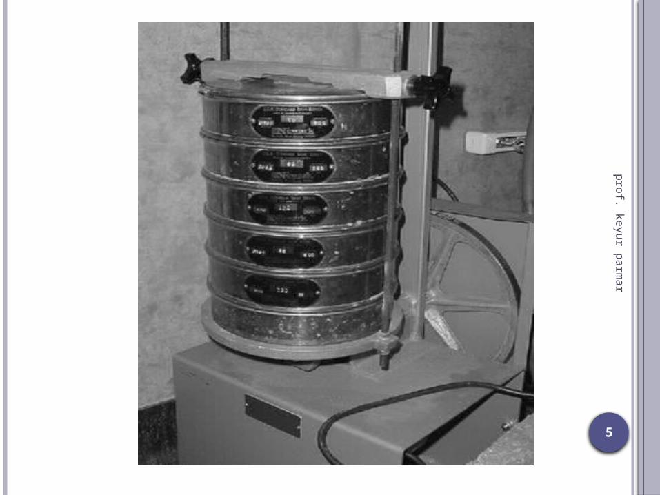
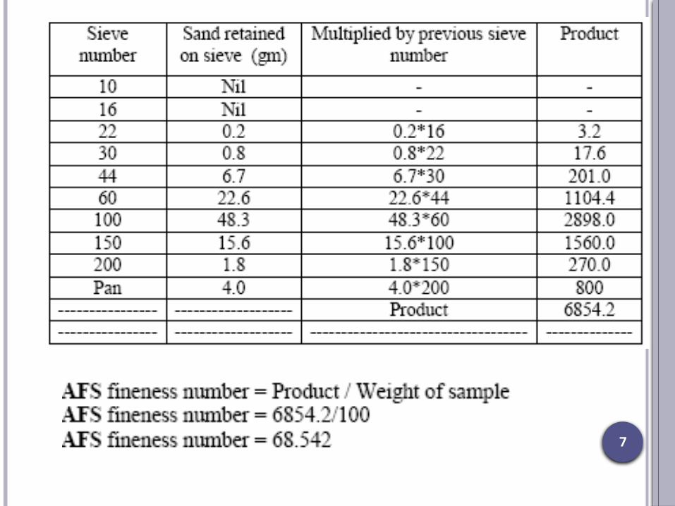
Grain fineness test: (Sieve Analysis Method)
A sample of dry silica sand 50g free from clay taken Place on topmost sieve bearing US series 6. A set of 11 screens bearing the standard mesh
number are 6,12,20,30,40,50,70,100,140,200,270 are mounted on mechanical shaker.
The series are place in order of fineness from top to bottom.
Shaking is done for 15 min. Weight of retained sand in each sieve is measured. The value of weight is multiply by 2 which gives %
weight. It will give the GFN number finally by simple
mathematics.
5
prof. keyur parmar

6
prof. keyur parmar
Sand Sieve analysis Tester for GFN
7
prof. keyur parmar
8
prof. keyur parmar
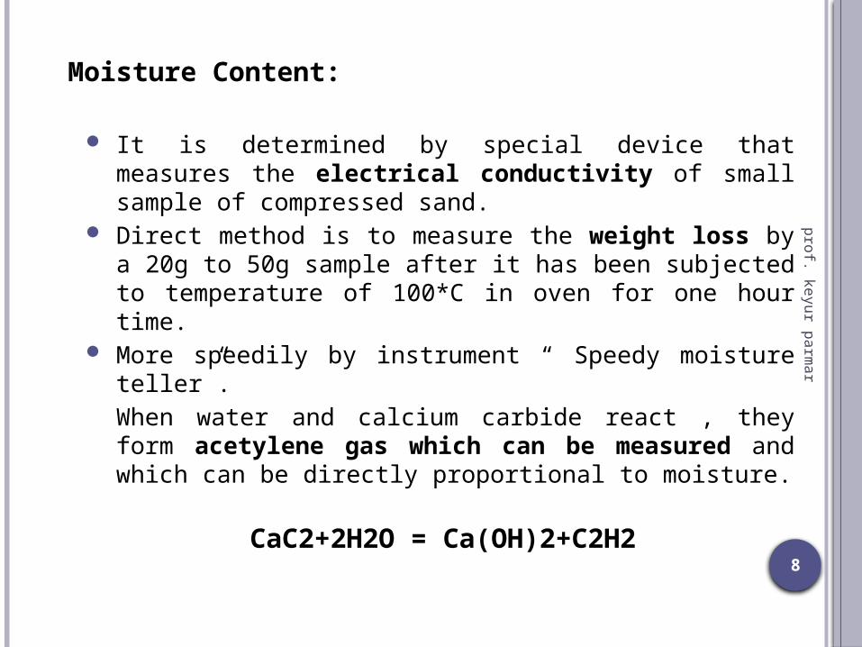
Moisture Content:
It is determined by special device that measures the electrical conductivity of small sample of compressed sand.
Direct method is to measure the weight loss by a 20g to 50g sample after it has been subjected to temperature of 100*C in oven for one hour time.
More speedily by instrument “ Speedy moisture teller”.When water and calcium carbide react , they form acetylene gas which can be measured and which can be directly proportional to moisture.
CaC2+2H2O = Ca(OH)2+C2H2

9
prof. keyur parmar

10
prof. keyur parmar
Clay content:
It is determined by washing the clay from 50-g sample of moulding sand , using water that contains sodium hydroxide to make it alkaline .
Several cycles of washing and agitation required to fully remove the clay.
The remaining sand is dried and weighed to determine the amount of clay removed from sample.
Clay in moulding sand of 50g is defined as particles which when suspended in water, fail to settle at a rate of 1inch per min. Clay consist of particle less than 20micron , per 0.0008inch in diameter.
11
prof. keyur parmar
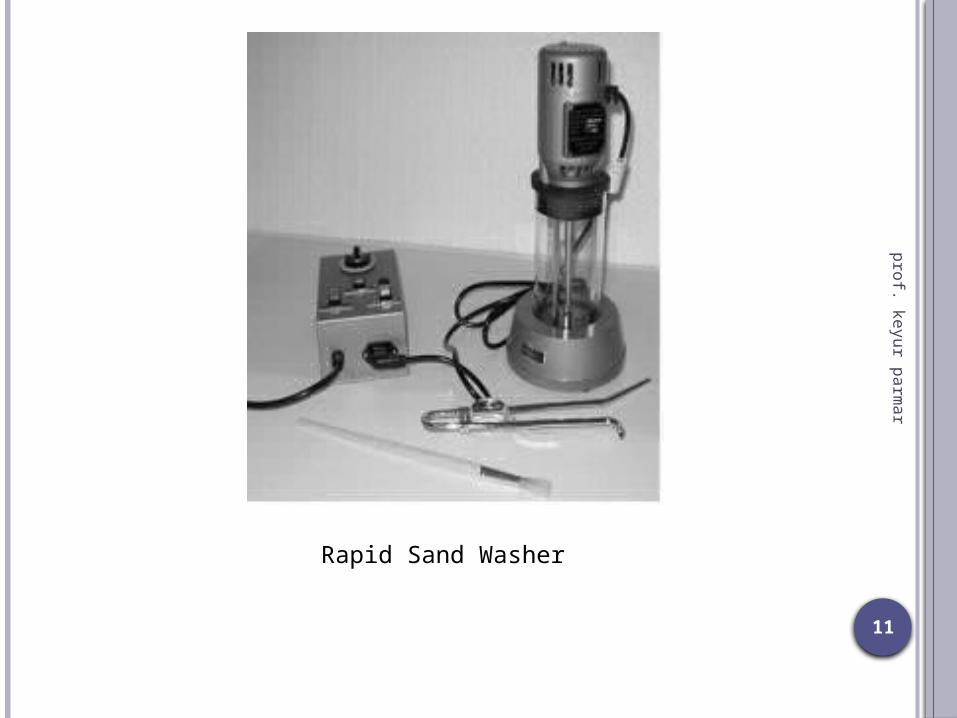
Rapid Sand Washer
12
prof. keyur parmar
Refractoriness Test:
It is found by heating the AFS specimen to very high temperature ranges depending upon the types.
Sand test piece are cooled at room temperature .
Examined under microscope for surface characteristics or by scratching it with steel needle.
Every time sand heated above 1000*C with a step interval of 50*C temp rise.
Again it is examined under microscope and needle scratch , till the sintering is not seen.

13
prof. keyur parmar
Strength Test:The sand specimen is placed in the lugs and
the pressure is applied using the hand wheel till the specimen breaks.
The reading of the needle of high and low pressure manometer indicates the compressive strength in kgf/sq.cm.
Bending, shear, compressive and tensile test are performed.

14
prof. keyur parmar
Permeability test:
It is conducted on compacted sand , using standard rammed specimen.
A amount of sand is first placed in a 2-inch (50.8mm) diameter steel tube.
A 14-lb (6.35kg) weight is dropped on it 3 times from the height of 2 inch (50.8mm).
A rammed specimen is subjected to an air pressure of 10g/sq.cm
Test is performed in permeability meter consisting of balanced tank, water tank, nozzle, adjusting lever, nose piece for fixing the sand rammed specimen and a manometer.
AFS number can be calculated directly from calibrated permeability meter.
15
prof. keyur parmar
Permeability is the volume of air in cubic cm. passing through a sand specimen of 1sq.cm cross sectional area and 1cm height at a pressure difference of 1gm/sq.cm in one minute.
In generalP = vh / patP = Permeabilityv = Volume air passing through specimenh = Height of specimen in cm.p = Pressure of air in gm/sq.cma = cross sectional area of specimen in sq.cm.t = time in min.
16
prof. keyur parmar
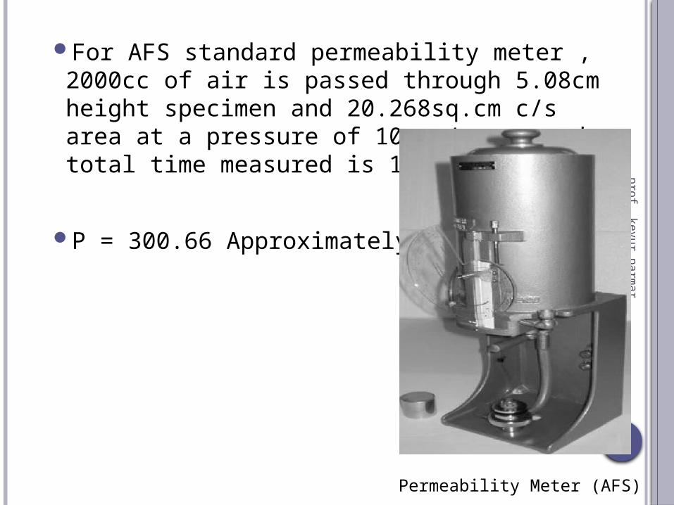
For AFS standard permeability meter , 2000cc of air is passed through 5.08cm height specimen and 20.268sq.cm c/s area at a pressure of 10gms/sq.cm and total time measured is 10sec = 1/6 min.
P = 300.66 Approximately.
Permeability Meter (AFS)

17
prof. keyur parmar
Check that the open orifice is in position in the center post.
Prepare a standard specimen of sand. Before stripping from tube, place in position on the center post and seal by rotating the knurled ring anti-clockwise.
Turn air valve to vent and raise air drum until it is above the water level.
Turn valve to close and allow the drum to descend slowly into the water. Turn the air valve gradually towards vent and allow the air drum to descend until the „X‟ mark on the drum is level with the top edge of the tank. Turn valve to „closed‟
Allow the air drum to descend by turning the air valve to a position midway between closed and vent.
Time the descent of the air drum between the zero and the 2000 ml mark with a stop watch and record the pressure indicated on the manometer during the descent of the drum.

18
prof. keyur parmar
Block Diagram of Permeability Meter

19
prof. keyur parmar
Green Compressive StrengthIt is determined by removing the rammed
from compacting tube and place in mechanical testing device.
A compressive load is applied until specimen breaks. Which usually occur in range of 10 to 30 psi.
Hardness:It is determined by resistance of the sand to
penetration of a 5.08mm diameter spring loaded steel ball.

20
prof. keyur parmar
Flowability:Put the sand in the steel cylinder.By movement of rammer plunger between
the 4th and 5th dropIt is indicated in percentage.This can be directly taken on the dial of the
flow indicator.Then the stem of this indicator again put on
the top of the plunger of hammer .It records the actual movement of plunger
between 4th and 5th drops.
21
prof. keyur parmar
Shatter Index Test:Put the sand in the steel cylinder.AFS standard specimen is rammed by 10
blowsAllowed to fall on a 1/2 inch mesh sieve
from height of 6 feet.The weight of sand retained in sieve is
measured.It is expressed as percentage of total weight
of the specimen which is a measure of shatter index.
22
prof. keyur parmar
Mould Hardness test:Performed by mould hardness tester.Principle is based on brinell hardness testing
machine.A ½ inch diameter steel hemi-spherical ball
is loaded with spring load of 980gm.The ball is made to penetrate the mould
sand and core sand surface.The dial indicates the penetration in
thousands of inch, which directly reads the hardness value.
The penetration of the probe into the mould surface is registered on the dial and is read direct as Green Hardness „B‟ Scale.
23
prof. keyur parmar
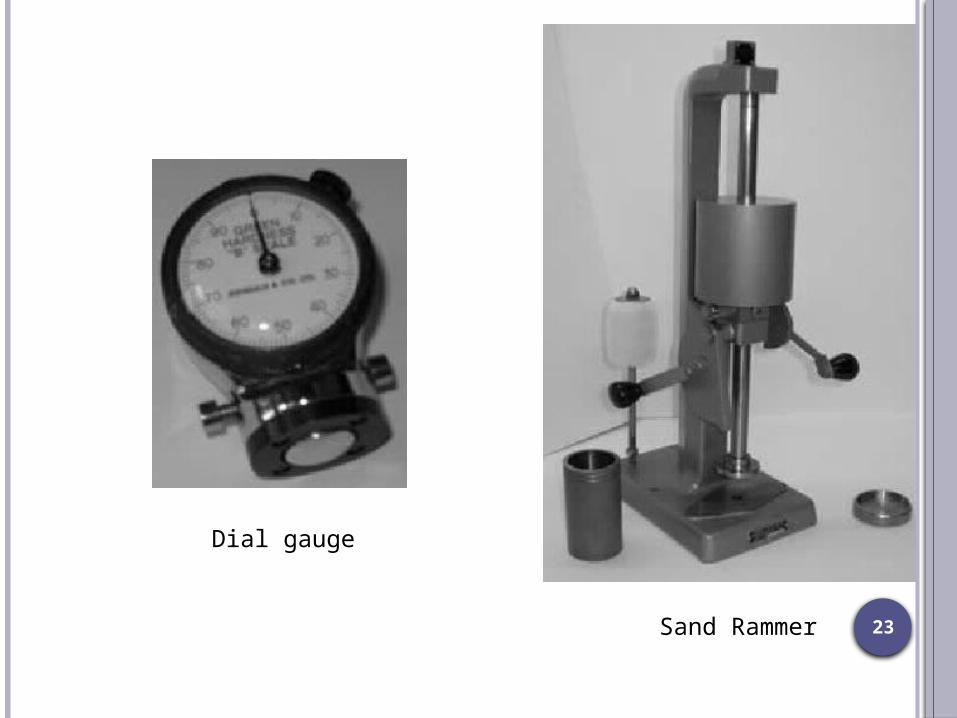
Dial gauge
Sand Rammer

24
prof. keyur parmar
CORE

25
prof. keyur parmar
Compact mass of core sand prepared separately that when placed in mould cavity at required location with proper alignment does not allow the molten metal to occupy the space for solidification in that portion and hence help to produce hollowness in casting.
Hollowness – Holes, recesses, Projections , undercut, internal cavities etc.
26
prof. keyur parmar
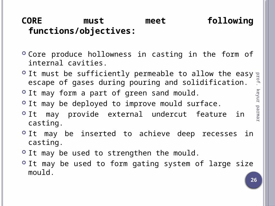
CORE must meet following functions/objectives:
Core produce hollowness in casting in the form of internal cavities.
It must be sufficiently permeable to allow the easy escape of gases during pouring and solidification.
It may form a part of green sand mould. It may be deployed to improve mould surface. It may provide external undercut feature in casting. It may be inserted to achieve deep recesses in
casting. It may be used to strengthen the mould. It may be used to form gating system of large size
mould.

27
prof. keyur parmar
CORE Sand:Special Kind of moulding sand. Consideration in selection of
Core sand are
Core sand should be High in refractory nature. Permeability should be high compare to moulding sand. It should not possesses any material which produce gas ,
while /during contact with molten metal. It must be collapsible in nature.
Constituents are : SILICA SAND (COARSE GRAINS) + BINDER (ORGANIC)
Binders : Cereal , Protein, Thermosetting resin, Sulphite, Dextrin, Pitch,
Molasses, Core oil.
28
prof. keyur parmar
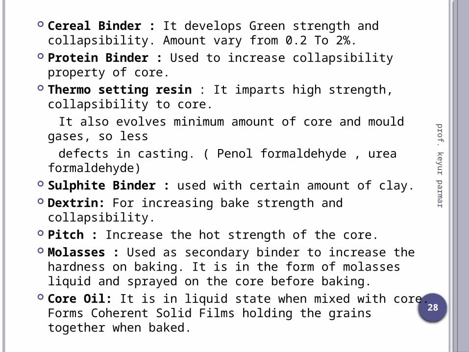
Cereal Binder : It develops Green strength and collapsibility. Amount vary from 0.2 To 2%.
Protein Binder : Used to increase collapsibility property of core.
Thermo setting resin : It imparts high strength, collapsibility to core.
It also evolves minimum amount of core and mould gases, so less
defects in casting. ( Penol formaldehyde , urea formaldehyde)
Sulphite Binder : used with certain amount of clay. Dextrin: For increasing bake strength and collapsibility. Pitch : Increase the hot strength of the core. Molasses : Used as secondary binder to increase the
hardness on baking. It is in the form of molasses liquid and sprayed on the core before baking.
Core Oil: It is in liquid state when mixed with core. Forms Coherent Solid Films holding the grains together when baked.
29
prof. keyur parmar
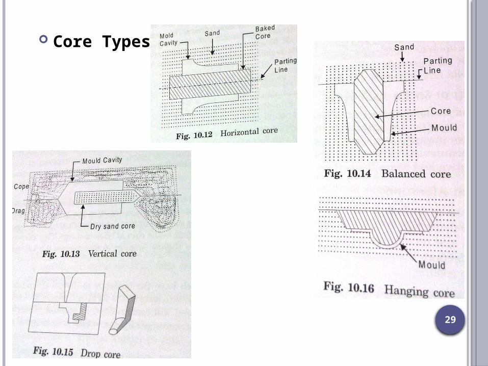
Core Types

30
prof. keyur parmar
CORE MAKING
It is carried out in four steps :Core Sand Preparation
Using Roller mills and core sand mixer.Core Making:
It is mechanized using core blowing, core ramming and core drawing machines.
Small bench blowers , Large floor blowers.Squeezing, jolting, slinging.Core drawing for deep draws is used. (rapping action on vibrator).
Core BakingTo remove moisture and harden the binder.To provide strength to core.Core oven and di-electric baker is used as dryer.

31
prof. keyur parmar
Core Finishing - Rubbing or filing of the surface to remove projections.
Core are coated with refractory and protective material using brushing, Deeping, spraying to improve the refractoriness and surface finish.
Bars , Wires and arbors used to reinforce core from inside. Also lifting rings are provided for heavy core.
32
prof. keyur parmar
CASTING DEFECTS
Defects generated due to : Improper Pattern Design
Improper Mould Construction
Improper Melting Practice
Improper Pouring Practice
Also from Moulding and core making materials.

33
prof. keyur parmar
Common Defects in casting: Blow Holes Misrun or Short run Cold Shut Mismatch Flashes Metal Penetration Drop Runout Cut or Wash Scars and Blisters Hard Spots Pinhole Porosity Shrinkage Cavities Hot Tears Sponginess Scab Swell Buckle Rat-Tail

34
prof. keyur parmar
CLASSIFICATION OF CASTING DEFECTSSurface Defects
Internal Defects
Visible Defects
Blow Blow Holes Wash
Scars Porosity Rat Tail
Blisters Pin Holes Swell
Drop Inclusions Misrun
Scab Dross Cold Shut
Penetration
Hot Tear
Buckle Shrinkage / Shit
35
prof. keyur parmar
CLASSIFICATION OF DEFECT IN CASTING (IITB)
SHAPE DEFECTSFlash , Mismatch, Core, Distortion
FILLING DEFECTSBlow hole, Cold shut, Gas porosity, Inclusions
SOLIDIFICATION DEFECTSShrinkage, Sink mark, Hot Tear , Fettling
36
prof. keyur parmar
BLOW HOLES: Well rounded cavities with clean and smooth surface. Appear on casting surface or in body of casting
(cavities). Reason – Excessive evolved gas entrapped in mould. It collects into a bubble at high point of mould cavity
and prevents the liquid metal to fill that space. Occur due to:
Excessive moisture content , organic content of sand moisture on chills, chaplets or metal inserts Less permeability of moulding sand Poor venting of mould Insufficient drying of mould and cores Cores not properly vented High gas content of molten metal Low pouring temperature Incorrect feeding of casting.
Usually occur on “COPE” of casting.

37
prof. keyur parmar

38
prof. keyur parmar
BLOW HOLES DEFECTS EXAMPLES

39
prof. keyur parmar
MIS RUN OR SHORT RUN:We call it as “Incomplete Filling of cavity”.Reason can be :
Inadequate metal supplyToo Low mould or melt temperature Improperly designed gatesLength to thickness ratio of casting is too large.

40
prof. keyur parmar
COLD SHUT:It is interface between casting , where two
metal streams meet without complete fusion.
41
prof. keyur parmar
MISMATCH: It is the shift of individual parts of a casting
with respect to each other.This may occur due to mould shift or core
shift.Reasons:
In expert assembling of the two halves of the mould.
From wear of pin bushes and pinsDimensional discrepancy between the core prints
of the pattern and core prints of the core.

42
prof. keyur parmar
43
prof. keyur parmar
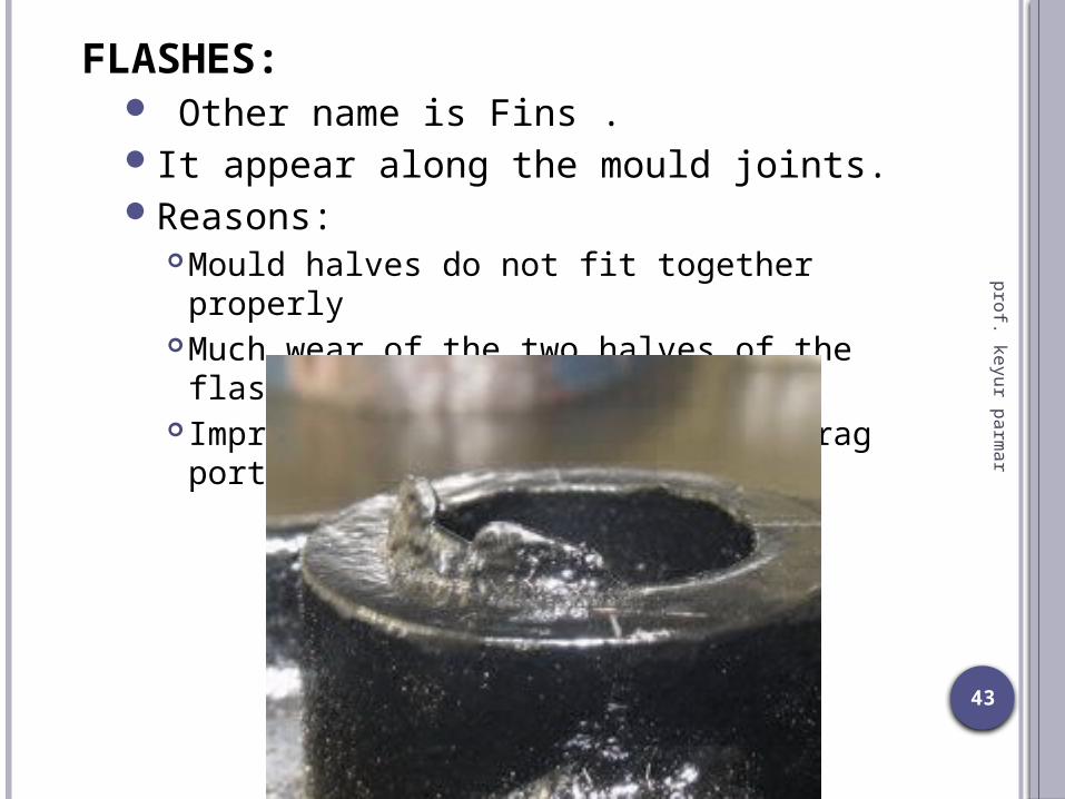
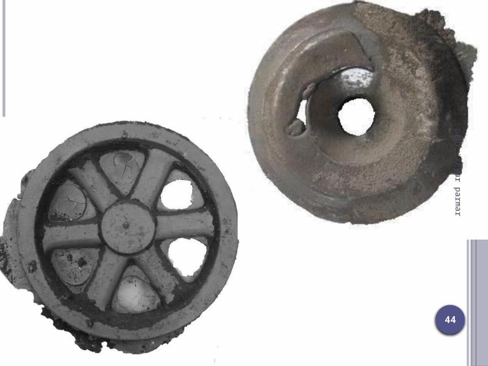
FLASHES: Other name is Fins .It appear along the mould joints.Reasons:
Mould halves do not fit together properlyMuch wear of the two halves of the flasks Improper fastening of cope and drag portion.
44
prof. keyur parmar
45
prof. keyur parmar
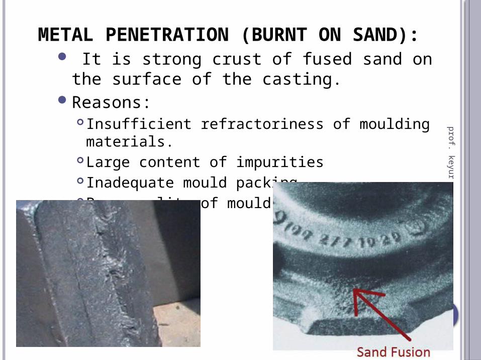
METAL PENETRATION (BURNT ON SAND): It is strong crust of fused sand on the
surface of the casting.Reasons:
Insufficient refractoriness of moulding materials.
Large content of impurities Inadequate mould packingPoor quality of mould wash.
46
prof. keyur parmar
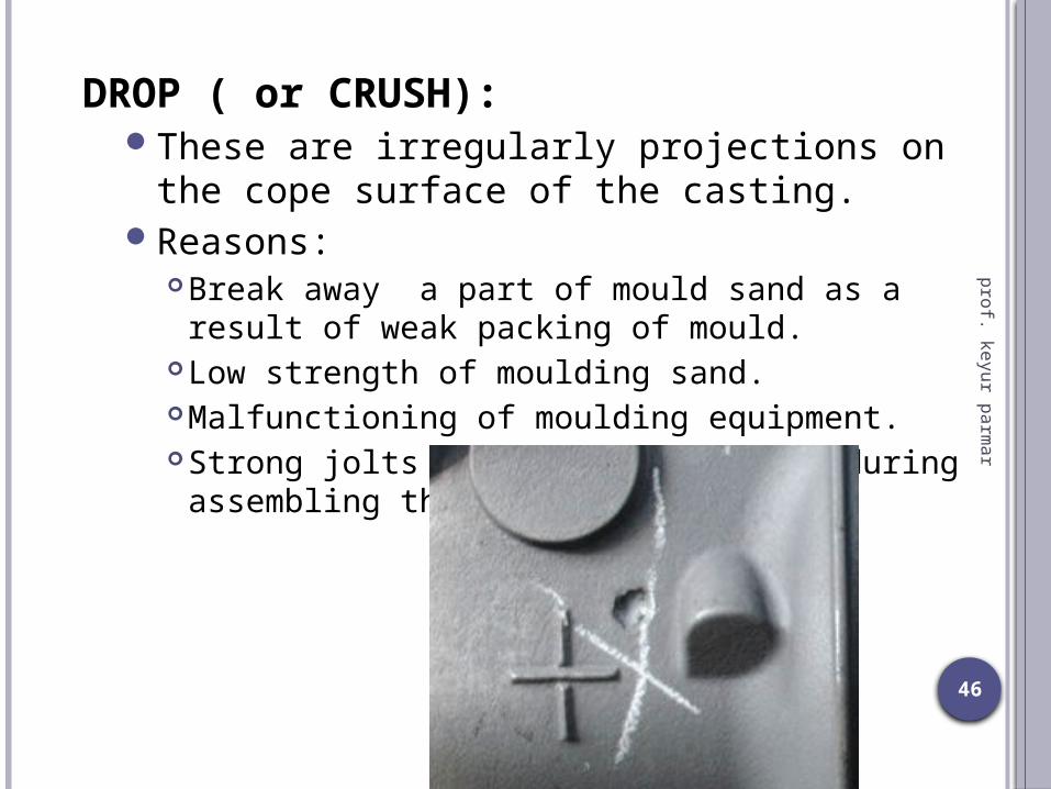
DROP ( or CRUSH):These are irregularly projections on the
cope surface of the casting.Reasons:
Break away a part of mould sand as a result of weak packing of mould.
Low strength of moulding sand.Malfunctioning of moulding equipment.Strong jolts and strikes at flask during
assembling the mould.

47
prof. keyur parmar
RUNOUT:In this metal is leaking out of a mould
during pouring.Reason:
Faulty moulding procedure or process.Faulty flask equipment.
48
prof. keyur parmar
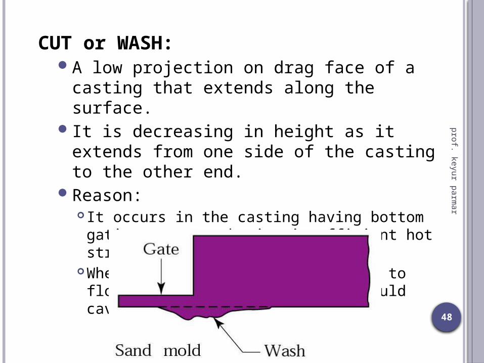
CUT or WASH:A low projection on drag face of a casting
that extends along the surface.It is decreasing in height as it extends from
one side of the casting to the other end.Reason:
It occurs in the casting having bottom gating system , having insufficient hot strength
When more amount of metal allowed to flow through one gate into the mould cavity.
49
prof. keyur parmar
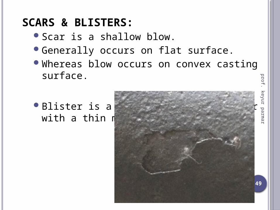
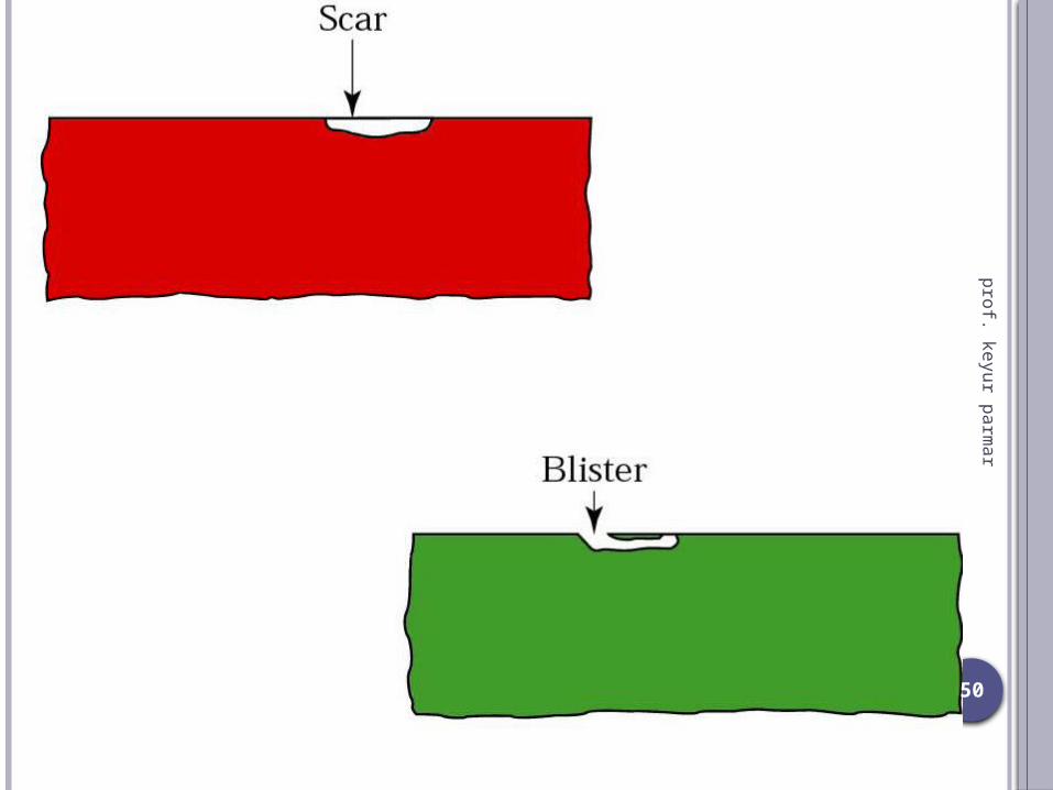
SCARS & BLISTERS:Scar is a shallow blow.Generally occurs on flat surface.Whereas blow occurs on convex casting
surface.
Blister is a shallow blow like a scar with a thin metal layer covering it.
50
prof. keyur parmar
51
prof. keyur parmar
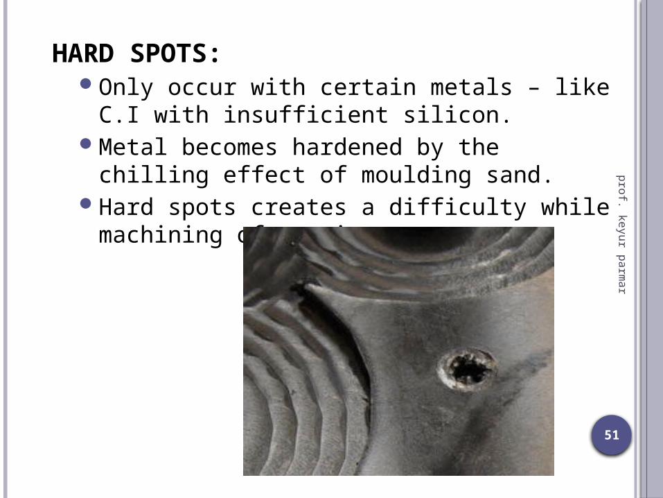
HARD SPOTS:Only occur with certain metals – like C.I with
insufficient silicon.Metal becomes hardened by the chilling
effect of moulding sand.Hard spots creates a difficulty while
machining of casting.
52
prof. keyur parmar
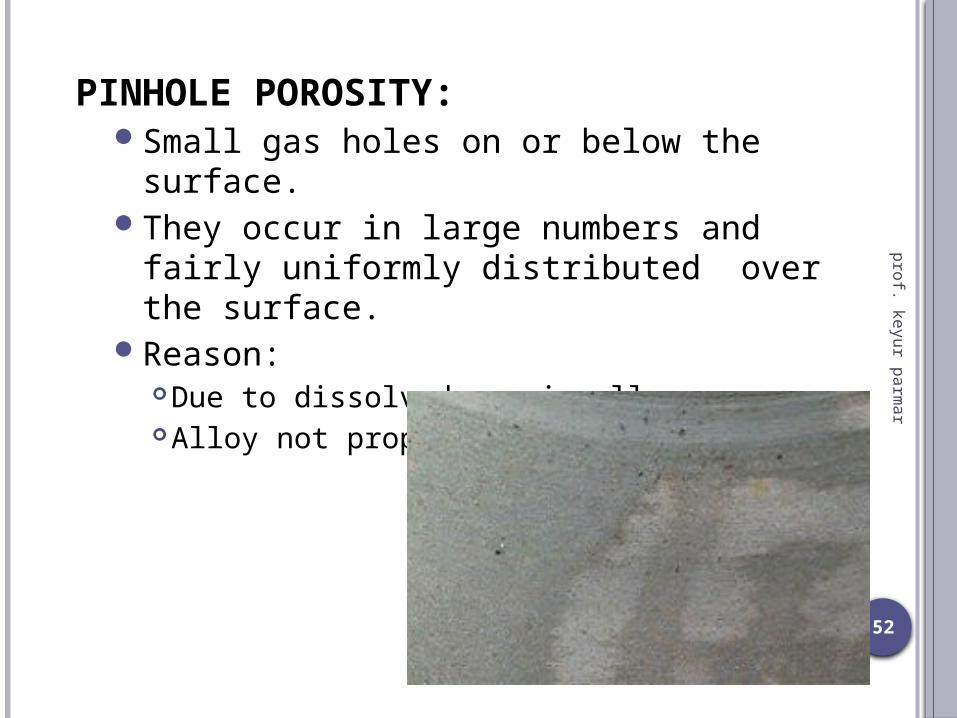
PINHOLE POROSITY:Small gas holes on or below the surface.They occur in large numbers and fairly
uniformly distributed over the surface.Reason:
Due to dissolved gas in alloyAlloy not properly degassed.

53
prof. keyur parmar
Gas porosity / pin hole porosity

54
prof. keyur parmar
SHRINKAGE CAVITIES: Internal void or depression in casting due to
volume contraction on solidification. It occurs at hot spot. Open shrinkage defects are open to
the atmosphere, therefore as the shrinkage cavity forms air compensates.
open air defects: pipes and caved surfaces. Pipes form at the surface of the casting and
burrow into the casting, while caved surfaces are shallow cavities that form across the surface of the casting.
Closed shrinkage defects, also known as shrinkage porosity, are defects that form within the casting.

55
prof. keyur parmar

56
prof. keyur parmar
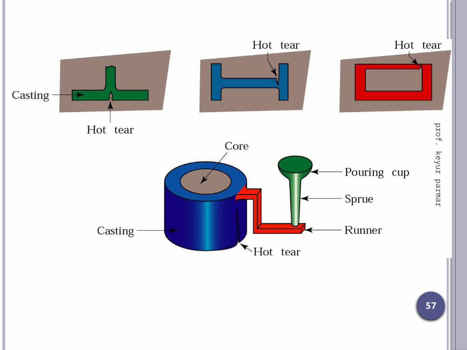
HOT TEARS:Hot cracks appear in the form of irregular
crevices with a dark oxidized fracture surface.Is a crack on casting surface usually near
a thick (hot, weak) section, caused by resistance of a hard mold or core to casting contraction.
Reason:When metal does not have sufficient strength to
resist tensile forces during solidification.Excessively high temperature of cast metal. Increased metal contraction. Incorrect design of gating system and casting as a
whole.Poor deformability / Collapsibility of the core. Internal stresses due to non-uniform cooling.
57
prof. keyur parmar

58
prof. keyur parmar
59
prof. keyur parmar
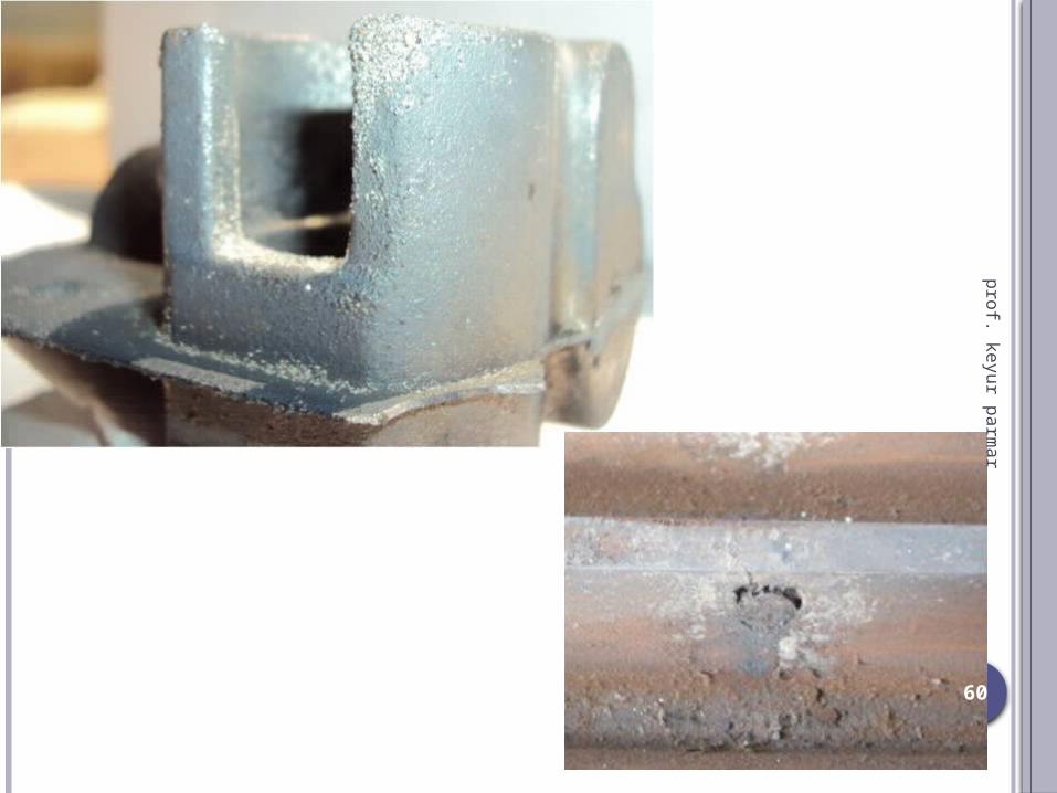
SPONGINESS (honeycombing):Large number of small cavities in close
proximity.Apparently occur on surface.Reason:
Suspension of dirt or inclusion in molten metal. Imperfect skimming of slag in the ladle. Incorrect gating system design.
Impurities being lighter comes up with evolved gases in the cavity.
60
prof. keyur parmar
61
prof. keyur parmar
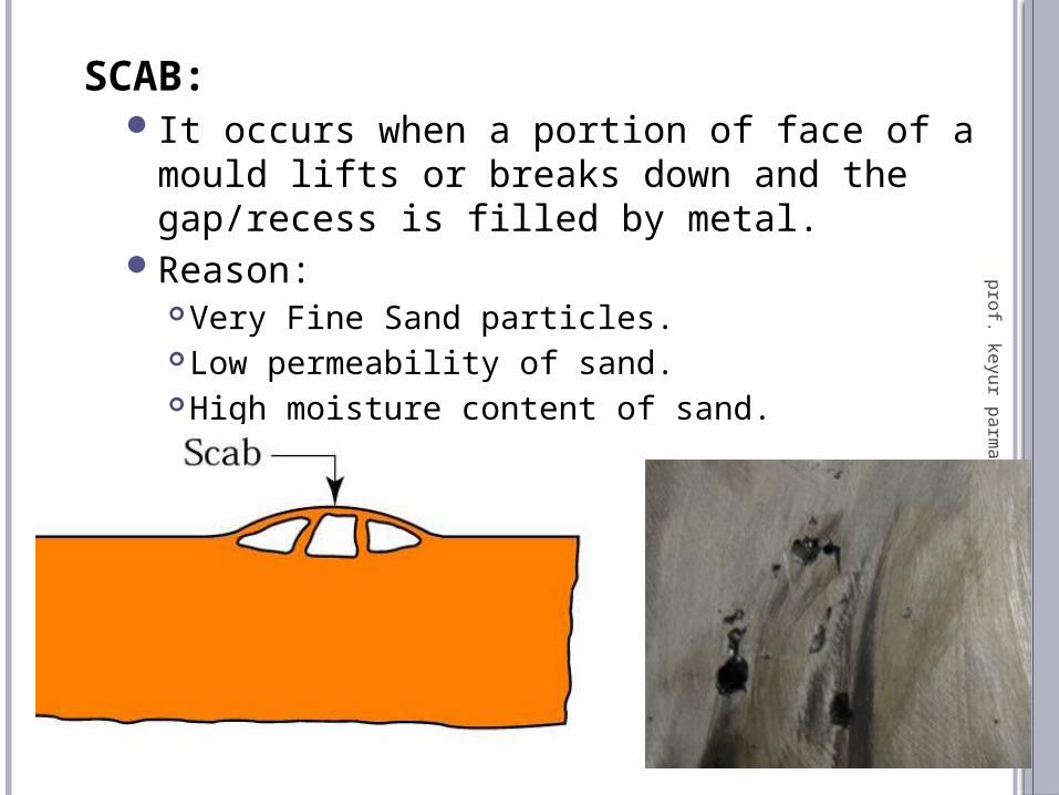
SCAB:It occurs when a portion of face of a mould
lifts or breaks down and the gap/recess is filled by metal.
Reason:Very Fine Sand particles.Low permeability of sand.High moisture content of sand.Uneven mould ramming.
62
prof. keyur parmar
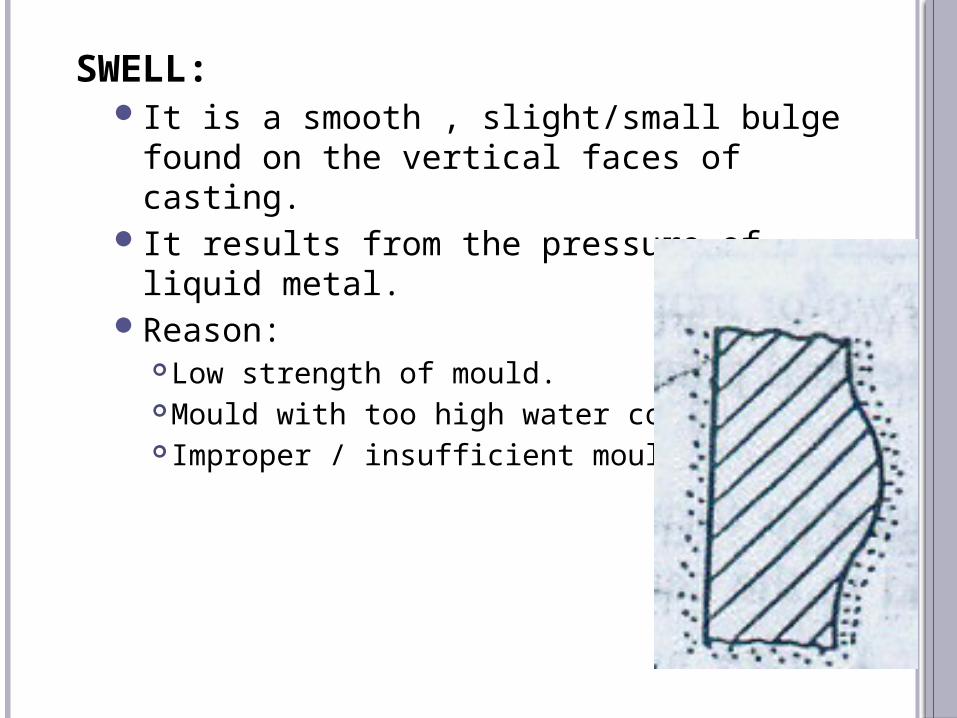
SWELL:It is a smooth , slight/small bulge found on
the vertical faces of casting.It results from the pressure of liquid metal.Reason:
Low strength of mould.Mould with too high water content. Improper / insufficient mould ramming.

63
prof. keyur parmar
BUCKLE:Long , shallow , V-shaped depression on
surface of flat casting.It extends in straight line on entire flat
surface.Reason:
Sand Expansion due to heat of metal.Poor casting design – Too much large flat area/
surface in mould cavity.Prevention:
Adding cereal or wood flour to sand .On burning / oxidation by molten metal a void
are created in mould which give space for expansion of sand particles and reduce compressive stresses.
64
prof. keyur parmar
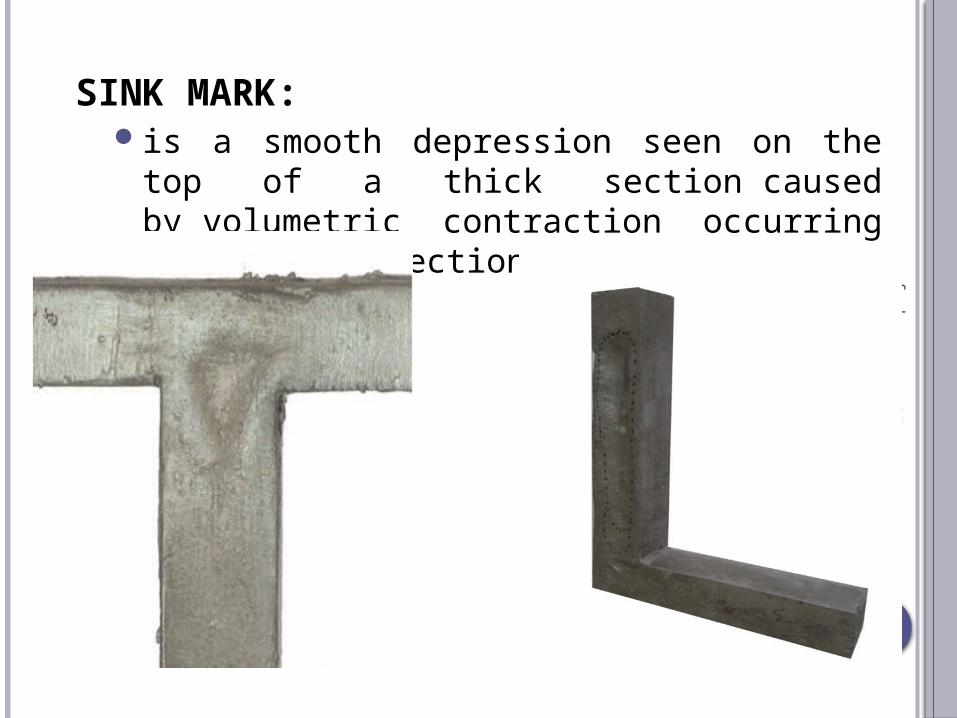
SINK MARK:is a smooth depression seen on the top of a
thick section caused by volumetric contraction occurring inside the section pulling the top surface.

65
prof. keyur parmar
RAT TAIL: (or Veins Defect)Long , Shallow , Angular depression in the
surface of flat casting.Reason are same as buckle.
66
prof. keyur parmar
REFERENCES
http://nptel.ac.in/courses/112107144/metalcasting/lecture1.htm
Core preparing - https://www.youtube.com/watch?v=3GtaL679lrw
http://www.iron-foundry.com/casting-defects-pictures.html
http://efoundry.iitb.ac.in http://www.foundryinfo-india.org/ https://www.youtube.com/user/TheEfoundry