Embed Size (px)
Citation preview

RTG 410
2
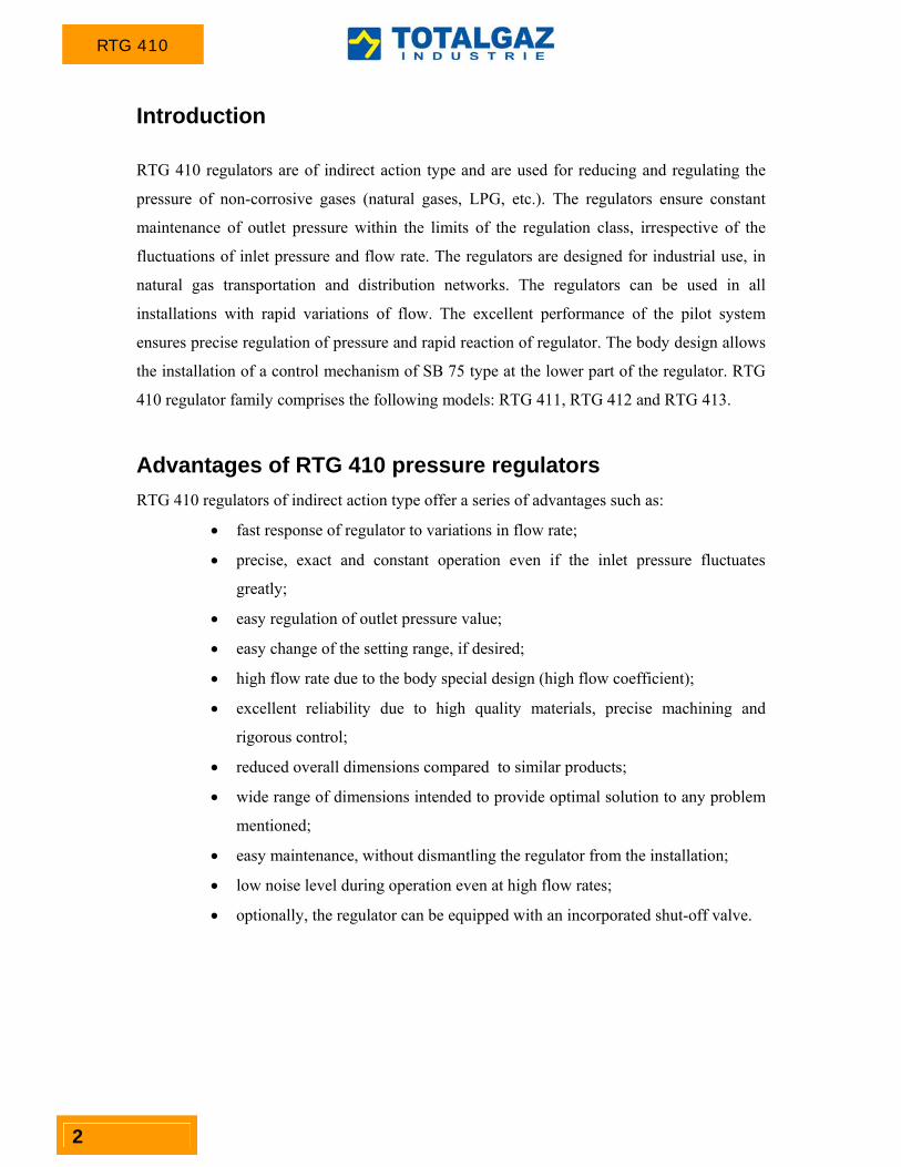
Introduction
RTG 410 regulators are of indirect action type and are used for reducing and regulating the
pressure of non-corrosive gases (natural gases, LPG, etc.). The regulators ensure constant
maintenance of outlet pressure within the limits of the regulation class, irrespective of the
fluctuations of inlet pressure and flow rate. The regulators are designed for industrial use, in
natural gas transportation and distribution networks. The regulators can be used in all
installations with rapid variations of flow. The excellent performance of the pilot system
ensures precise regulation of pressure and rapid reaction of regulator. The body design allows
the installation of a control mechanism of SB 75 type at the lower part of the regulator. RTG
410 regulator family comprises the following models: RTG 411, RTG 412 and RTG 413.
Advantages of RTG 410 pressure regulators
RTG 410 regulators of indirect action type offer a series of advantages such as:
fast response of regulator to variations in flow rate;
precise, exact and constant operation even if the inlet pressure fluctuates
greatly;
easy regulation of outlet pressure value;
easy change of the setting range, if desired;
high flow rate due to the body special design (high flow coefficient);
excellent reliability due to high quality materials, precise machining and
rigorous control;
reduced overall dimensions compared to similar products;
wide range of dimensions intended to provide optimal solution to any problem
mentioned;
easy maintenance, without dismantling the regulator from the installation;
low noise level during operation even at high flow rates;
optionally, the regulator can be equipped with an incorporated shut-off valve.

RTG 410
3
Figure 1 - RTG 410 operating diagram

RTG 410
4
Figure 2 – Monitor operating diagram

RTG 410
5
Figure 3 – Operating diagram of SB 750 shut-off valve
RTG 410
6
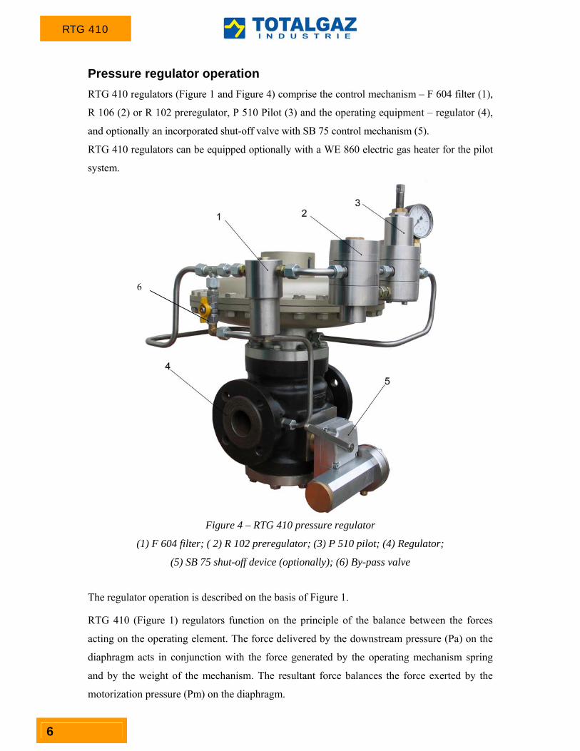
Pressure regulator operation
RTG 410 regulators (Figure 1 and Figure 4) comprise the control mechanism – F 604 filter (1),
R 106 (2) or R 102 preregulator, P 510 Pilot (3) and the operating equipment – regulator (4),
and optionally an incorporated shut-off valve with SB 75 control mechanism (5).
RTG 410 regulators can be equipped optionally with a WE 860 electric gas heater for the pilot
system.
Figure 4 – RTG 410 pressure regulator
(1) F 604 filter; ( 2) R 102 preregulator; (3) P 510 pilot; (4) Regulator;
(5) SB 75 shut-off device (optionally); (6) By-pass valve
The regulator operation is described on the basis of Figure 1.
RTG 410 (Figure 1) regulators function on the principle of the balance between the forces
acting on the operating element. The force delivered by the downstream pressure (Pa) on the
diaphragm acts in conjunction with the force generated by the operating mechanism spring
and by the weight of the mechanism. The resultant force balances the force exerted by the
motorization pressure (Pm) on the diaphragm.
6

RTG 410
7
Since the regulator is normally closed, in the absence of pressure in the control equipment
circuit, the operating mechanism piston is maintained in closed position by the spring.
Fluctuations in the upstream pressure do not modify this position because the piston is
completely balanced and exposed to equal pressure acting on surfaces with equal areas. The
rod is also balanced.
The gas in the control mechanism is taken from the regulator inlet, then passes through F 604
filter and undergoes an initial pressure reduction in R 102 preregulator. The pilot feeding
pressure (Pep) is obtained at the preregulator outlet and depends on the regulator outlet
pressure. The pilot feeding pressure is applied at the P 510 pilot inlet, thus generating the
motorization pressure (Pm) acting on the lower side of the operating mechanism diaphragm.
The value of the outlet pressure (Pa) can be modified by turning the pilot adjustment screw
[clockwise to increase (Pm) and, consequently, (Pa) and anticlockwise to decrease them]. If
the pressure (Pa) downstream of the regulator decreases because of an increase in the required
flow rate, this induces an imbalance in the pilot mobile subassembly, which results in the
modification of the motorization pressure (Pm) value and, implicitly, in a different balance
position of the adjustment element. An increase of the pressure downstream of the regulator
changes the balance position of the pilot mobile subassembly and leads to the decrease of the
motorization pressure (Pm) [at a certain value of the downstream pressure (Pa), the pilot
moves to closed position]; the (Pm) pressure decreases and the force exerted by the spring
causes the adjustment element in the regulator to move to closed position. Continuous
operation is ensured by the relief nozzle in the pilot, through which the gas at (Pm) circulates
towards the outlet pipe (Pa).

RTG 410
8
Technical characteristics
Table 1 indicates the technical characteristics of RTG 410 regulators, part of which are also
listed on the product specification plate on delivery.
Table 1 – Technical characteristics of RTG 410 regulators
Regulator type RTG 411
RTG 411 SB RTG 411 M
RTG 412 RTG 412 SB RTG 412 M
RTG 413 RTG 413 SB RTG 413 M
Inlet/ outlet connection diameter Flange Dn 25Dn 400
PN16PN20/ANSI Class 150
Flange Dn 25Dn 300 PN25PN50/ANSI
Class 300
Flanşa Dn 25Dn 300 PN25PN50/ANSI
Clasa 300
PN64PN110/ANSI Class 600
Inlet pressure [bar] 0.2 ÷ 16/20 0.4 ÷ 40/50 0.5 ÷ 40/50 0.5 ÷ 100
Outlet pressure [bar] 0.2 ÷ 12 0.2 ÷ 49 0.5 ÷ 75
Differential pressure Δp [bar] 0.2 0.4 0.5
Working medium Natural gases (SR 3317–2003), other non-corrosive gases
Ambient temperature [oC] -30 ÷ 80
Working medium temperature [oC] -20 ÷ 60
Intervention accuracy class (AG)
‐ minimum up to 2.5%
‐ maximum up to 1%
(depending on the control pressure)
Accuracy class (AC) ± 1 ÷ 5% ± 1 ÷ 5% ± 1 ÷ 2.5%
Lock-up pressure class (SG) 2.5 ÷ 10% 1 ÷ 5% 1 ÷ 2.5%
Materials
The external surfaces of the regulator are painted and zinc coated in order to provide anti-
corrosion protection.
Table 2 - Materials
Part Material
Body ASTM A216 WCB, ASTM A352 LCB Seat Stainless steel Rod Stainless steel Covers Carbon steel Internal parts Stainless steel, aluminium alloy, brass Valve plate Rubber (NBR) or polyurethane Diaphragms Rubber (NBR) with textile insert, Rubber (NBR) O-rings Rubber (NBR), Viton, HNBR

RTG 410
9
Pressure regulator selection
When selecting the pressure regulator, the following data should be considered:
- inlet pressure
- outlet pressure
- maximum flow rate
- working medium
- working medium temperature
- ambient temperature
According to SR EN 334+A1:2009, the flow coefficient Cg is taken into consideration when
selecting the regulator size. The maximum flow rate is established assuming that the regulator
is totally open.
The following formulas are used to determine the maximum flow rate:
a) in subcritical conditions, when 5.0e
a
P
P
aaeg
e
PPPCtd
Q
273
57.13
Or: aaeg PPPKQ
b) in critical conditions, when 5.0e
a
P
P
eg
e
PCtd
Q
.)273(
78.6
Or: eg P
KQ
2
Symbols:
Q – flow rate [Nm3/h]
Pe – absolute inlet pressure [bar]
Pa – absolute outlet pressure [bar]
Cg – air flow coefficient [m3/h x bar], according to Table 3
Kg – natural gas flow coefficient [Nm3/h]
d – relative density (for air d = 1)
te – natural gas temperature at regulator inlet
Relative densities for other working fluids are listed in Table 4.
For natural gas, the formulae based on Kg coefficient can be directly used (the formulae

RTG 410
10
already contain the correction for natural gas at t = 15ºC).
Table 3 - RTG 410 regulator flow coefficient
DN Cg Cg Cg KG KG KG Nominal diameter
RTG 410 RTG 410 + SB 750
RTG 410 + AM 814
RTG 410 RTG 410 + SB 750
RTG 410 + AM 814
25 567 510 306 585 527 316
40 1475 1328 801 1523 1370 827
50 2233 2010 1224 2305 2075 1263
80 4633 4170 2548 4783 4304 2630
100 8070 7263 4664 8331 7498 4815
150 16787 15108 9485 17329 15596 9791
200 26465 23819 14767 27320 24588 15245
250 38810 34929 21734 40064 36057 22436
300 65157 58641 36488 67262 60536 37667
Table 4 – Gas relative density
Gas Relative density (d) Air 1.0
Propane 1.53 Butane 2.0
Nitrogen 0.97 Oxygen 1.14
Carbon dioxide 1.52
Gas velocity is also considered when selecting the pressure regulator and sizing the pipes.
For regulators, the recommended gas velocity in the outlet flange is less than 150 m/s. The
erosion phenomenon accelerates and the noise level increases significantly at greater velocity.
The pipes are sized for gas velocities lower than 20 m/s.
Gas velocity in the outlet flange or in pipes is calculated using the formula:
ai
a
PD
PQV
1
002.0192.345 2
where:
V – gas velocity [m/s]
Q – flow rate [Sm3/h]
Di – inside diameter [mm] (for regulators RTG 410 Di = Dn)
Pa – outlet pressure [barg]

RTG 410
11
Safety devices and optional accesories
Pilot equipment
The pilot equipment mounted on the regulators included in RTG 410 family comprises: - micro-filter F 604 series
- gas electric heater WE 860 series (optionally)
- preregulator R 100 (R 102 or R 106) series
- pilot P 510 (P 510, P 510 A, P 510 HP, P 511) series
The type of pilot mounted in the regulator depends on the required outlet pressure value (Pa).
Thus:
P 510 A Wh = 0.015 ÷ 1 bar P 510 P 510 HP
Wh = 0.20 ÷ 12 bar Wh = 4 ÷ 30 bar
P 511 Wh = 10 ÷ 75 bar
Table 5 – Adjustment springs for P 510 pilots
Pilot Code Setting
range[bar]
P 510 A
1450224 0.02 ÷ 0.10
1450226 0.02 ÷ 0.40
1450227 0.1 ÷ 1
P 510
1450228 0.2 ÷ 0.6
1450229 0.5 ÷ 2
1450230 1 ÷ 3.5
1450231 2 ÷ 7
1450232 4 ÷12
P 510 HP
1450284 3 ÷ 8
1450285 6 ÷ 14
1450286 10 ÷ 26
1450287 20 ÷ 32
P 511 1450234 10 ÷ 25
1450235 20 ÷ 40
1450236 30 ÷ 75

RTG 410
12
Monitor
The monitor (Figure 2) is an emergency regulator which comes into operation in the
regulating process when the pressure downstream of the regulator increases up to the monitor
set pressure.
There are two assembling solutions: with incorporated monitor or in-line monitor.
Incorporated monitor
In this case, the emergency regulator (monitor) is directly assembled on the body of the main
regulator. Both regulators use the same body, except that:
- they are governed by two different pilots, separately assembled;
- they operate on different surfaces of the same seat.
The monitor can be mounted on RTG 410 regulator already installed without major
modifications.
In-line monitor
The monitor is installed in line upstream of the operating regulator and is identic with the
main regulator. The control pressure of the monitor is collected downstream of the working
regulator and the pressure acting on the pilot equipment on the working regulator is collected
upstream of the monitor.
SB 750 shut-off valve operation
The valve (Figure 3 and 5) working position is normally open. When the regulated pressure
(Pa) is within the set range, the shut-off valve is open. The load of the Pa pressure on the
diaphragm (1) of the servomotor (Figure 5) maintains the rod (2) in balance position. Thus,
the cam (7) movement under the action of the spring is obstructed by the fork (5) whose radial
movement is induced by the rod (2). When the Pa pressure exceeds the maximum allowable
value, the force of the spring (4) is overcome, which causes the rod (2) to move. The fork (5)
releases the cam (7) which moves under the action of the spring (6) and releases the valve
plate holder (9). When the Pa pressure decreases below the minimum allowable value, the
force of the spring (3) moves the rod (2) which rotates the fork (5) and releases the cam (7)
which in its turn moves under the action of the spring (6) and releases the piston. The
movement of the valve plate holder (9) under the action of the spring (8) closes the valve.
Sealing is ensured by O-rings and seat valve plate.

RTG 410
13
Figure 5 - SB 750 shut-off valve

RTG 410
14
Table 6 – Adjustment springs for SB 75 control mechanism
Servomotor type
Minimum spring Maximum spring
Code Adjustment range [bar]
Code Adjustment range [bar]
SM 15
1450353 2.4 ÷ 4.8 1450367 21.3 ÷ 42.7 1450354 4.1 ÷ 8.3 1450368 41.9 ÷ 83.8 1450355 8.0 ÷ 15.6 1450358 9.0 ÷ 18.2 1450359 17.8 ÷ 35.7 1450360 34.9 ÷ 62.1
SM 20
1450353 1.3 ÷ 2.7 1450367 12.0 ÷ 24.0 1450354 2.3 ÷ 4.6 1450368 23.5 ÷ 47.2 1450355 4.5 ÷ 8.7 1450358 5.1 ÷ 10.2 1450359 10.0 ÷ 20.1 1450360 19.6 ÷ 34.9
SM 25
1450354 1.4 ÷ 3.0 1450368 15.1 ÷ 30.2 1450355 2.9 ÷ 5.6 1450359 6.4 ÷ 12.8 1450360 12.5 ÷ 22.4
SM 37
1450352 0.2 ÷ 0.5 1450366 2.04 ÷ 4.1 1450353 0.4 ÷ 0.9 1450367 3.9 ÷ 7.8 1450354 0.7 ÷ 1.5 1450368 7.6 ÷ 15.4 1450355 1.4 ÷ 2.9 1450358 1.6 ÷ 3.3 1450359 3.2 ÷ 6.5 1450360 6.4 ÷ 12.4
SM 50
1450351 0.06 ÷ 0.14 1450364 0.27 ÷ 0.55 1450352 0.12 ÷ 0.25 1450365 0.53 ÷ 1.07 1450353 0.21 ÷ 0.44 1450366 1.0 ÷ 2.0 1450354 0.37 ÷ 0.75 1450367 1.9 ÷ 3.8 1450355 0.72 ÷ 1.40 1450368 3.7 ÷ 7.6 1450356 0.21 ÷ 0.43 1450357 0.42 ÷ 0.85 1450358 0.81 ÷ 1.63 1450359 1.60 ÷ 3.20 1450360 3.13 ÷ 5.60
SM 70
1450351 0.03 ÷ 0.08 1450361 0.02 ÷ 0.04 1450352 0.06 ÷ 0.1 1450362 0.03 ÷ 0.081450353 0.1 ÷ 0.2 1450363 0.06 ÷ 0.14 1450354 0.1 ÷ 0.4 1450364 0.13 ÷ 0.28 1450355 0.3 ÷ 0.7 1450365 0.27 ÷ 0.55 1450356 0.1 ÷ 0.2 1450366 0.51 ÷ 1.02 1450357 0.2 ÷ 0.5 1450367 0.98 ÷ 1.95 1450358 0.4 ÷ 0.8 1450368 1.92 ÷ 3.85 1450359 0.8 ÷ 1.7 1450360 1.6 ÷ 2.9

RTG 410
15
Incorporated silencer
Optionally, RTG 410 pressure regulator can
be equipped with an AM 814 internal
silencer.
The internal silencer is selected depending on
the specific operating conditions. It ensures
noise level reduction of up to 20 dB.
The installation of an internal silencer leads
to a decrease in the flow coefficient (Cg) to a
value ranged 20 ÷ 30%.
Figure 6 – AM 814 silencer
WE 860 electric heater
WE 860 gas heaters are mounted in the circuit of the pilot equipment which controls indirect
acting pressure regulators. WE 860 heaters ensure that gas temperature is high enough before
expansion, thus preventing the forming of hydrates and the frost resulted from the phenomena
specific to the gas pressure reduction process.
Figure 7 - Component elements and overall dimensions of WE 860
(1) Connection; (2) Heating element; (3) Central body; (4) Cover; (5) Shell; (6) Connection

RTG 410
16
Assembly diagram of RTG 410 regulator family
In order to ensure proper operation of the regulator, it is recommended to observe the diagram
in Figure 8.
Figure 8 – RTG 410 assembly example
The FTG 600 and WTG 630 heaters are recommended.
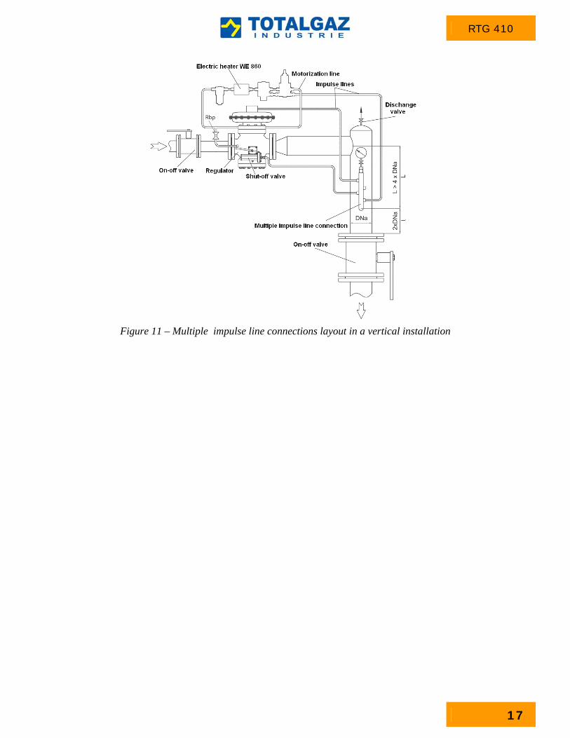
The control pressure for the regulator and the shut-off valve must be taken off downstream of
the regulator, according to the diagrams in Figures 10 and 11.
The impulse line connections layout must be as per Figure 9.
correct correct incorrect
Figure 9 – Impulse line connections layout
Figure 10 – Multiple impulse line connections layout in a horizontal installation
RTG 410
17
Figure 11 – Multiple impulse line connections layout in a vertical installation

RTG 410
18
Overall dimensions
Figure 12 – Overall dimensions
Table 7 – RTG 410 regulator overall dimensions
Nominal diameter
Dn
RTG 411 (Pn 16;
Clasa 150)
RTG 412 (Pn 25; Pn 40
Clasa 300)
RTG 413 (Pn 64; Pn 100
Clasa 600)
A [mm]
B [mm]
C [mm]
A [mm]
B [mm]
C [mm]
A [mm]
B [mm]
C [mm]
25 184 435 125 197 442 127 210 454 134 40 222 470 140 235 475 142 246 495 150 50 254 495 155 267 560 145 286 530 170 80 298 545 200 317 552 204 336 570 212 100 352 620 210 368 625 215 394 650 225 150 451 750 230 473 758 235 508 772 250 200 543 870 275 568 880 281 609 900 298 250 673 930 350 708 937 362 752 985 382 300 737 1020 382 770 1028 396 804 1050 405 400 1016 1476 495 - - - - - -

RTG 410
19
Ordering code
The pressure regulator is identified by specifying the constructive variant, the nominal
dimensions of the inlet – outlet connections and the maximum working pressure.
Example:
For example, the RTG 411 – 50 – 16 – SB 750 – AM – P 510 –WE – M notation designates a
regulator of 411 type with DN 50, maximum working pressure of 16 bar, provided with an
incorporated SB 750 shut-off valve, incorporated silencer, P 510 pilot, gas heater for the pilot
system and monitor.
Additional requirements, if any, must be specified when placing the order.

TOTALGAZ INDUSTRIE
Nr. R.C.: J-22-3277/1994 CUI: RO6658553
IBAN: RO28BRDE240SV13842272400
B.R.D. G.S.G. Iaşi
Şos. Păcurari, nr. 128, Iaşi, cod 700545, România Tel. : 0040-232-216.391(2) Fax : 0040-232-215.983 E-mail: [email protected] Web: www.totalgaz.ro
Certified Management System
The manufacturer reserves the right to make modifications without any prior notification.
CT No. 215 / 2009 / 01