Embed Size (px)
Citation preview

C SeriesCorn Header
Operator's Manual 215099 Revision A
Original Instruction
The harvesting specialists.

INTRODUCTION
1
INTRODUCTION
Dear Customer,
The following is some useful information provided to help ensure efficient and safe operation
of this corn head.
This manual gives some information regarding the C-series corn heads.
Read this manual carefully to learn how to operate and service your machine correctly.
Failure to do so could result in personal injury or equipment damage.
This manual should be considered a permanent part of your machine and should remain
with the machine when you sell it.
Since the corn head can be mounted to many models of combines, carefully read your
combine specifications and follow the combine manufacturer’s recommendations for usage,
set-up and operation of the combine.

TABLE OF CONTENTS
2
TABLE OF CONTENTS
1. SAFETY .................................................................................................................................... 4
1. SAFETY DECALS ................................................................................................................... 6
1.1 RECOGNIZE SAFETY INFORMATION ................................................................................................ 6 1.2 SAFETY LABEL MEANINGS .............................................................................................................. 7
2. OPERATION AND FUNCTION .......................................................................................... 14
3. IDENTIFICATION AND SPECIFICATIONS ................................................................... 17
3.1. IDENTIFICATION ........................................................................................................................... 17 3.2. SPECIFICATIONS ........................................................................................................................... 18
3.2.1. Dimensions ................................................................................................................................................. 18 3.2.2. Gearbox Lubricant: EP-00 (liquid) grease, and SAE 80W-140 standard lubricating oil. ........................... 18 3.2.3. Pitch of the gathering auger: 560 mm (22”). .............................................................................................. 18 3.2.4. Input shaft speed of the snapping unit drive: 550 rpm ................................................................................ 18 3.2.5. Length of chopped stalk: average 50 mm, depending on crop conditions. ................................................. 19 3.2.6. Adjustment of the snapping plate: central in-cab control switch. ............................................................... 19 3.2.7. Available row spacing: 20” – 22” – 30” (50.8 cm – 56 cm – 76.2 cm) with addition of specified snouts and
dividers. ................................................................................................................................................................ 19
4. SHIPPING CONDITIONS .................................................................................................... 20
5. MOUNTING THE CORN HEAD ON THE COMBINE ................................................... 22
5.1. MOUNTING THE CORN HEADS ON THE COMBINE .......................................................................... 22 5.1.1 John Deere 60, 70 and s series ..................................................................................................................... 22 5.1.2. CASE IH 1000-2000 .................................................................................................................................. 23 5.1.3. CIH Flagship & Legacy; NH CR & CX; similarly MF 9000, & 9500 Series;
R55/65/75, R66/76, & S Series ............................................................................................................................. 23 5.1.4. MF 8500 Series ........................................................................................................................................... 24 5.1.5. Claas Lexion 500, 600 and 700 series ........................................................................................................ 24
5.2. OTHER STEPS FOLLOWING THE SECURING OF THE ADAPTER ON THE COMBINE ........................... 25
6. RUN-IN PROCEDURE ......................................................................................................... 30
7. SETUP PROCEDURE AND ADJUSTMENT OF THE CORN HEAD ........................... 31
7.1. FRAME .......................................................................................................................................... 31 7.2. AUGER .......................................................................................................................................... 32
7.3. Timings of the auger: ..................................................................................................................................... 33 7.3. INPUT GEARBOX DRIVE ............................................................................................................... 35 . 7.4. SNAPPING UNITS ........................................................................................................................... 35
7.4.1. Snapping rolls adjustment ........................................................................................................................... 36 7.4.1.1. Distance between snapping roll shafts ..................................................................................................... 36 7.4.1.2. Labyrinth.................................................................................................................................................. 36 7.4.2. Snapping plate adjustment .......................................................................................................................... 37 7.4.3. Vine knife adjustment ................................................................................................................................. 39 7.4.4. Gathering chain adjustment ........................................................................................................................ 40 7.4.5. Gearbox timing and backlash adjustment ................................................................................................... 41
7.5. HEADER DRIVE SHAFTS ............................................................................................................... 42

TABLE OF CONTENTS
3
7.6. CLEARANCE LIGHTS ..................................................................................................................... 42 7.7. PLASTIC SNOUT ADJUSTMENT ...................................................................................................... 43
8. HARVESTING ....................................................................................................................... 44
8.1. STALK CHOPPER ........................................................................................................................... 45
9. ROW SPACING ADJUSTMENT ........................................................................................ 46
10. MOUNTING TO ANOTHER TYPE OF COMBINE ........................................................ 46
11. MAINTENANCE AND LUBRICATION ............................................................................ 47
11.1. FRAME .......................................................................................................................................... 47 11.2. AUGER .......................................................................................................................................... 47
11.2.1. Folding corn head - snapping unit connecting clutches ............................................................................ 48 11.2.2. Folding corn head - auger connecting clutches ......................................................................................... 48
11.3. INPUT GEARBOXES ................................................................................................................. 49 11.4. DRIVE COMPONENTS ............................................................................................................. 50
11.4.1. U-joint shafts: .................................................................................................................................... 50 11.4.2. Chain couplings ................................................................................................................................. 50
11.5. SNAPPING UNIT ........................................................................................................................ 51 11.5.1. Gearboxes .......................................................................................................................................... 51 11.5.2. Snapping roll ............................................................................................................................................. 54 11.5.3. Gathering chain ......................................................................................................................................... 55
12. ELECTRICAL SCHEMATICS ........................................................................................... 56
12.1. JD ELECTRICAL SCHEMATIC ......................................................................................................... 56 12.2. CNH ELECTRICAL SCHEMATIC ..................................................................................................... 57 12.3. AGCO ELECTRICAL SCHEMATIC .................................................................................................. 58 13.4. CLAAS LEXION ELECTRICAL SCHEMATIC ................................................................................... 59 13.5. CIH 1000 AND 2000 SERIES ......................................................................................................... 60
14. TROUBLE SHOOTING ....................................................................................................... 61
14.1. A LARGE QUANTITY OF EARS BUILDS UP BETWEEN THE AUGER AND FEEDER. ............................ 61 14.2. IN LAID OR LODGED CORN STALKS, THE STALKS DO NOT FEED PROPERLY INTO THE SNAPPING
ROLLS. ..................................................................................................................................................... 61 14.3. ROW UNIT BECOMES PLUGGED WHILE HARVESTING LAID OR LODGED CORNSTALKS. ................. 61 14.4. STALKS, GRASS OR WEEDS WRAP ON THE SNAPPING ROLL. ......................................................... 61 14.5. AUGER DOES NOT ROTATE. .......................................................................................................... 61 14.6. EARS ARE BROKEN OR SPLIT IN THE AUGER. ................................................................................ 61 14.7. DIFFICULTY IN KEEPING THE CORN HEAD PROPERLY ON THE ROW.............................................. 61
15. OFF-SEASON STORAGE OF YOUR CORN HEAD ....................................................... 62
16. WARRANTY, SERVICE, SPARE PARTS ORDERING .................................................. 62
17. LUBRICATION CHART ...................................................................................................... 63
18. PRE-DELIVERY & PRE-HARVESTING INSTRUCTIONS .......................................... 65
18.1 PRE-DELIVERY INSPECTION ............................................................................................................... 65 18.1 PRE-HARVESTING INSPECTION .......................................................................................................... 66

SAFETY
4
1. SAFETY
This is the safety-alert symbol. When you see this symbol on your machine or in this
manual carefully read the message that follows, and be alert to the possibility of
personal injury or death.
Follow recommended precautions and safe operating procedures.
UNDERSTAND SIGNAL WORDS
A signal word – DANGER, WARNING, or CAUTION – is used with the safety-alert
symbol. DANGER identifies the most serious hazards.
DANGER or WARNING safety decals are located near specific hazards. General
precautions are listed on CAUTION safety decals. CAUTION also calls attention to
safety messages in this manual.
FOLLOW SAFETY INSTRUCTIONS
Carefully read all safety messages in this manual and on your machine safety decals.
Keep safety decals in good condition. Replace missing or damaged safety decals. Be
sure new components and repair parts include current safety decals.

SAFETY
5
GENERAL SAFETY GUIDELINES
1. ALLOW ONLY TRAINED AND EXPERIENCED OPERATORS TO OPERATE
THIS MACHINE. Operating this equipment safely requires the full attention of the
operator. Do not wear entertainment headphones while operating this machine.
2. ALWAYS DISENGAGE header drive, shut off the engine and remove key before
service, adjustment, maintenance and lubrication of the corn head.
3. STAY CLEAR of the header when it is in operation.
4. DO NOT OPEN safety shields or covers while the corn head is running.
5. ENGAGE the lock on the feeder lift cylinder before doing any work under or around the
corn head.
6. WORN OR DAMAGED CHOPPER KNIVES must be replaced before operation of
the corn head. Radial clearance between knife and bushing must be properly maintained.
See details in this manual.
7. NEVER remove the warning labels from the machine. If they become damaged or
illegible order replacement parts as shown in the Figures.
8. NEVER remove the safety hydraulic valve of the folding corn heads, located on the back
of the corn head.
9. NEVER close or open the folding corn head when it is in operation.

SAFETY
6
1. SAFETY DECALS
1.1 Recognize safety information
Carefully read Operator’s Manual before operating the machine. When operating, always
observe safety instructions.
WARNING!
This is the safety – alert symbol.
When you see this symbol on your machine or in this manual, be alert to the
potential for personal injury. Carefully read all safety messages in this manual and
on your machine safety signs, and respect them fully to avoid accidents leading to
serious injury or death!
WARNING!
Keep safety signs in good condition. Replace missing or
damaged safety signs. Replacement safety signs are available
from the manufacturer. It is PROHIBITED to remove safety
signs from your machine!
WARNING!
Before installing the machine read the operator’s manual
carefully, learn how to operate, control and keep your machine
in good condition. Do not let anyone operate it without
instruction.
1.326.700
Keep your machine in proper working condition. Unauthorized and non-professional
modifications to the machine may impair the function and safety and affect the
machine life.

SAFETY
7
1.2 Safety label meanings The function of the labels is to give, easy to understand safety instructions for those
who are staying close to the machine, in order to minimize the risk of accidents. It is
therefore important that these labels always be easy to read, and in complete
condition.
a. Before beginning any maintenance or lubricating, stop the
engine of the combine and remove the key!
1.326.703
b. If you stop the combine while the header is lifted, secure the
loose working cylinder with the help of the device - dive
inhibitor - fixed to the hydraulic working cylinder of the
combine to avoid the accidental crash of the header.
1.326.701
c. Always stay clear of moving elements during operation!
Always disengage header drive, shut off the engine and
remove key before servicing or unclogging header.
1.315.438
d. Always keep your distance from the rotating parts of the
machine. The header’s snapping rolls and other moving
parts can’t be covered completely due to their functions. Do
not feed crop material into machine by hand or attempt to
manually unplug machine while it is running. The stalk rolls
can feed the crop material in faster than you can release
your grip on it. To avoid personal injury or mortal accident
always stop engine before unclogging.
1.326.702

SAFETY
8
e. Never attempt to open or remove shield while the engine is
running. Keep every shield in its place. Avoid direct contact
of your hand, leg, any part of your body or cloth with
rotating, moving machine parts, elements! Before
approaching any moving parts wait for them to completely
stop!
1.326.705 1.379.142
f. Avoid bruise!
The loose and non-fixed header can unexpectedly crash
down, so stay away from loose and non-fixed machine!
1.315.439
g. If the engine is still operating, the combine can accidentally
start. Never step between the header and the combine if the
engine is not shut off!
1.379.143
h. Machines equipped with chopper are more dangerous
because of objects thrown out unexpectedly. Do not stay
close to operating machine. Follow the instructions on use
and maintenance of chopper knives!
1.315.440
i. When we are talking about foldable machines there's a
possibility that the wing frames can suddenly fold. Do not
stay under and around the wing frames!
1.326.707

SAFETY
9
j. On some types of corn heads you can find high-pressure
hydraulic system. In case of a pressurized system, the
piping system must not be disturbed or exposed to any
external effects of the damage.
1.332.254
k. The drive shaft rotation.
1.332.252-3
l. To prevent injury from sharp cutting blades: Do NOT
operate without shields in place. Disengage power take-off,
stop engine and remove key before opening covers. Stop
engine and remove key before opening shield. Blades may
continue to rotate after power is shut off. Listen and look for
evidence of rotation before opening shield.
1.372.836
m. To prevent injury from entanglement with rotating auger:
Stand clear of auger while machine is running.
1.372.837
n. Before putting the machine into operation, please remove
the screws which fasten the main frame and side frames on
both sides at delivery.
1.372.916
o. Lifting points on the lifting bar.
514.038.0

SAFETY
10
p. Tie-down point locations.
1.372.890
q. Chopper knife covers are marked with safety decals. Do
NOT operate without covers in place.
1.373.044
r. Operating the machine with feeder lateral tilt feature
enabled may result in damage!
1.379.138
s. QR code label leading to the C-series page.
1.372.822

SAFETY
11
LIST OF ACTIVE MACHINE PARTS
No. Active machine part Danger
1. Snapping units, gathering chains Snatch, entanglement
2. Gathering auger Cutting, entanglement
3. Outside shields Nip, bruise
4. Side chain drive Snatch, entanglement
5. Drive shafts Entanglement
6. Inner space between combine and corn
head
Crushing
7. Stalk chopper Cutting, impact from unexpected flying objects
8. Shields, snouts Slipping , stumbling
9. Lifted machine Crushing
10. Hydraulics High-pressure fluid injection
5 2
8
4
3
10
10
1

SAFETY
12
Illustration below shows placement of safety decals
The figure shows the
placement of machine safety
decals.
Attention! The figure shows
only the labels on one side of
the header, but in reality the
decals must be placed
symmetrically on both sides.
Type Numbers:
C3006C
C3008
C3008C
C3012C
C3012CF
C2212C
C3006
C2208
C2208C
C3008F
C3008CF
C2012
C2012C
C2212
C3012
C3012F
C3808
C3808C

SAFETY
13
Window frame decals:
AGCO
CLAAS/LEXION
JOHN DEERE
CASE IH
CNH
GLEANER RS
AGCO, IDEAL

OPERATION AND FUNCTION
14
7
2. OPERATION AND FUNCTION
The MacDon corn head can be mounted on most combines. Corn ears are detached from the
corn stalks as is shown on the illustration below. The corn stalk enters the area between the
snapping rolls (1,2) which counter-rotate relative to each other, and are pulled downwards
between the snapping plates (3) by the rolls (1,2). This downward directing action causes
the corn ears (5) to impact the snapping plates (3), detaching the ear from the stalk in the
process. The detached ears are moved rearward by the gathering chains (6) into the auger
trough (7) and are conveyed to the combine feeder house by the cross auger (8). Corn stalks
are discharged downward by the snapping rolls (1,2).
If the corn head is equipped with optional stalk chopper, the stalks are chopped into small
fragments by this chopper, located under the snapping rolls.
Attention!
For safe corn head operation, it is essential to respect the instructions on the use of the
corn head when mounted to the combine. Only qualified operators should operate the
machine.
8 6
7

OPERATION AND FUNCTION
15
Operation
The corn head is driven from the combine feeder shaft through a universal drive shaft or
chain shaft coupling. Power is transmitted from the drive shaft by gears encased in an oil bath
to a shaft which passes through the snapping unit.
Torque limiting clutches transmit power from the shaft to each snapping unit.
The auger is chain driven through a torque limiting clutch from the left side snapping unit
drive (or from both sides of large corn heads).
Consider and follow each of the following sequence guidelines before starting operation of
the corn head:
after a sounding horn start the engine of the combine
after ensuring that no one is close to the corn head and combine, lower the corn head
into operation position using the combine “lower” function switch
1. Operate the corn head only in the specified harvesting position
2. Engage the combine feeder drive and begin harvesting.
3. Operate at a ground speed that does not exceed that suitable for the combine and corn head
capacity and ground conditions.
4. Perform an emergency stop
During harvesting be aware of unexpected events that may take place requiring immediate
shutdown of the forward movement or combine feeder drive.
Such events could be:
accident
foreign materials in the crop (irrigation pipe, gas tube, rocks etc.)
which could enter the corn head
excessive crop loading (action of torque limiting clutches)
clogging or blockage
other breakdown or fault

OPERATION AND FUNCTION
16
The corn head has no specific emergency stop system. The emergency stop is actuated
using the combine systems located in the combine cab. Understand and respect the
relevant instructions of the combine emergency stop procedures as related to the corn
head.
Never leave the combine cab while corn head is in operation.
Non-conforming use:
The corn head is designed only for harvesting in the direction of planting (row
dependant) and for the specified row widths. Harvesting performance can greatly
deteriorate if the corn head is used in other conditions for which it is not intended.
Deterioration in performance can result if:
The corn head is positioned too high or too low during harvesting
The corn head is used to harvest crops other than corn.

IDENTIFICATION AND SPECIFICATIONS
17
3. IDENTIFICATION AND SPECIFICATIONS
3.1. Identification
The universal mounting of the corn head permits it to be attached to specific combine types
with the appropriate mounting kit. A mounting kit is assembled to the corn head at the
factory as ordered.
A data plate is located on the left side of the corn head upper beam.
The model number refers to the following: for example:
C3012 12-row fixed frame with 30” row spacing
C3012C 12-row fixed frame with 30” row spacing and stalk chopper
C3012CF 12-row folding frame with 30” row spacing and stalk chopper

IDENTIFICATION AND SPECIFICATIONS
18
3.2. Specifications 3.2.1. Dimensions
3.2.2. Gearbox Lubricant: EP-00 (liquid) grease, and SAE 80W-140 standard lubricating
oil.
3.2.3. Pitch of the gathering auger: 560 mm (22”).
3.2.4. Input shaft speed of the snapping unit drive: 550 rpm
Row Spec Model Chopper
Weight Width
Length
(mm)
Length in
shipping
condition
(mm)
Height
(mm)
Height in
shipping
condition
(mm) Kg Lbs mm ft.
6R30 C3006 No 2073 4570 4609 15,1 2970 1100 1410 2430
C3006C Yes 2180 4800 4609 15,1 2970 1100 1410 2430
8R22 C2208 No 2140 4720 4744 15,56 2970 1100 1449 2430
C2208C Yes 2260 4982 4810 15,78 2970 1100 1449 2430
8R30 C3008 No 2968 6543 6135 20,1 2970 1100 1449 2430
C3008C Yes 3110 6856 6135 20,1 2970 1100 1449 2430
8R38 C3808 No 2900 6390 7553 24,78 2970 1100 1449 2430
C3808C Yes 3080 6790 7553 24,78 2970 1100 1449 2430
12R20 C2012 No 2890 6370 6324 20,75 2970 1100 1449 2430
C2012C Yes 3050 6724 6390 20,96 2970 1100 1449 2430
12R22 C2212 No 3325 7330 6984 22,91 2970 1100 1449 2430
C2212C Yes 3630 8000 7050 23,13 2970 1100 1449 2430
12R30 C3012 No 3906 8611 9180 30,1 2970 1100 1449 2430
C3012C Yes 4120 9083 9180 30,1 2970 1100 1449 2430
Row Spec
Model Chopper
Weight Transport
width Width
Length
(mm)
Length in
shipping
condition
(mm)
Height
(mm)
Height in
shipping
condition
(mm) Kg Lbs mm ft. mm ft.
12R30 C3012F No 4156 9162 4750 15,6 9180 30,1 2970 1100 1584 2430
C3012CF Yes 4370 9634 4750 15,6 9180 30,1 2970 1100 1584 2430
8R30 C3008F No 3218 7094 3226 10,6 6135 20,1 2970 1100 1584 2430
C3008CF Yes 3360 7408 3226 10,6 6135 20,1 2970 1100 1584 2430
Combine
Backshaft speed Header Speed
Range Rated 11 tooth 12 tooth 15 tooth 18 tooth
NH fixed drive 575 - - 575 - -
NH variable drive 402-575 550 - 402-575 - -
AGCO fixed drive 617 - 673 - - -
AGCO variable drive 608-975 825 - - - 405-650
JD fixed drive 520 - 567 - - -
JD variable drive 520-785 688 - - 416-628 -
Case-1000-2000 series 500 - 545 - - -
Case AFX variable drive 460-690 596 - 460-690 - -
Lexion fixed drive 761 - - - 609 -
Lexion variable drive 508-737 688 - - 406-590 -

IDENTIFICATION AND SPECIFICATIONS
19
3.2.5. Length of chopped stalk: average 50 mm, depending on crop conditions.
3.2.6. Adjustment of the snapping plate: central in-cab control switch.
3.2.7. Available row spacing: 20” – 22” – 30” – 38” (50.8 cm – 56 cm – 76.2 cm – 96,5
cm) with addition of specified snouts and dividers.
SHIPPING CONDITIONS
20
4. SHIPPING CONDITIONS
The corn head is delivered mounted on a shipping skid suitable for handling by forklift.
Lifting rings are also provided suitable for overhead lifting.
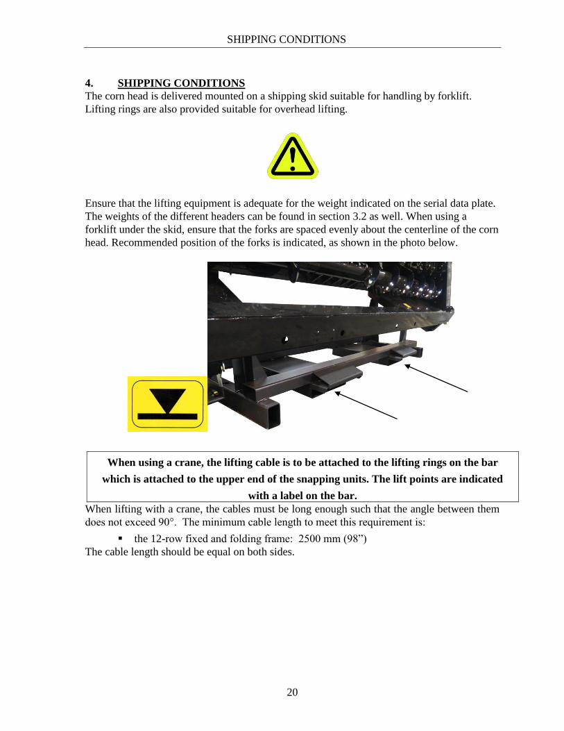
Ensure that the lifting equipment is adequate for the weight indicated on the serial data plate.
The weights of the different headers can be found in section 3.2 as well. When using a
forklift under the skid, ensure that the forks are spaced evenly about the centerline of the corn
head. Recommended position of the forks is indicated, as shown in the photo below.
When using a crane, the lifting cable is to be attached to the lifting rings on the bar
which is attached to the upper end of the snapping units. The lift points are indicated
with a label on the bar.
When lifting with a crane, the cables must be long enough such that the angle between them
does not exceed 90°. The minimum cable length to meet this requirement is:
the 12-row fixed and folding frame: 2500 mm (98”)
The cable length should be equal on both sides.

SHIPPING CONDITIONS
21
NOTE: Only use a cable with specified capacity that meets the weight of the machine.
When lifting a 12-row corn header use four cables as shown in the photo below.
max. 90º

MOUNTING TO THE COMBINE
22
5. MOUNTING THE CORN HEAD ON THE COMBINE
While the corn head is mounted on shipping stand
Remove the parking stands and snouts from the shipping position and install parking
stands in their retracted position
Carefully lower the corn head to horizontal position with a cable attached to lifting
hooks
Remove the shipping skid after the machine is resting securely in horizontal position
The corn head is shipped from the factory with mounting kit installed as ordered. If the corn
head will be mounted to a different combine than ordered, remove the factory installed
mounting kit and install the required mounting kit as recommended for your combine with all
the specified drive line shielding.
After the above operation and with the specified mounting kit securely attached to the
Corn Head, engage and securely attach the Corn Head to the combine according to
Combine Manufacturer’s instructions. Engage the feeder lift cylinder safety stop and
secure the lower latches.
5.1. Mounting the corn head on the combine
5.1.1 John Deere 60, 70 and S series
Insert the spring pivot pin (2) of the feeder house into the hole of the retainer plate (1) which
is assembled on the lower support. If required, adjust the pin alignment.

MOUNTING TO THE COMBINE
23
5.1.2. CASE IH 1000-2000
Adjust the nuts on the U-bolts (1) as required to provide adequate clamping force. Refer to
the combine operator’s manual for the correct adjustments and latching methods.
5.1.3. CIH Flagship & Legacy; NH CR & CX; similarly Challenger MF 9000 Series;
Gleaner N, A, R, & S Series
Adjust the position of the latch retainer (1) to ensure that the feeder lever is fully engaged. If
the proper position is not attainable, change the original arm of the feeder with the arm
supplied as an attachment.

MOUNTING TO THE COMBINE
24
5.1.4. MF 8500 Series
Adjust the nuts on the U-bolts (1&2) as required to provide adequate clamping force (3).
Refer to the combine Operator’s Manual for the correct adjustments and latching methods.
5.1.5. Claas Lexion 500, 600, 700, 7000, & 8000 series; similarly IDEAL 7, 8, & 9

MOUNTING TO THE COMBINE
25
5.2. Other steps following the securing of the adapter on the combine
Attach the Snouts
Place the central snouts onto the rear divider pins (1). For easier mounting, first loosen the
rear divider pin which is secured by a hex bolt (2), secure the central snouts from the outside
with Torx-head bolts (3) and then tighten the loosened hex bolts. Refer to the parts manual.
Adjust the arm which is used for central snout support (4), to the desired height and then
secure it with a hex bolt (5) and a lock nut (6). If finer adjustment is needed, this can be done
with a nut in the back (7). The recommended settings can be found at chapter 7.7.
The outer snouts are installed in a similar way. The outer LH and RH snout supports are
unique and must be installed correctly to properly contact the underside of the snouts.
Remove the Lifting Bar
Remove the lifting bar from the snapping unit ONLY after the corn head is properly attached
and secured to the combine, and the combine feeder lift cylinder stop is engaged.
2
4
5;6
1;3
7

MOUNTING TO THE COMBINE
26
For folding headers only:
Remove shipping bolt and plate securing each wing to the central frame so header will be
allowed to fold.
Connect Header Drive Shafts
Connect the drive shafts and ensure that the protective shields are properly in place and that
all rotating parts are adequately shielded. The shafts are installed at the factory with
protective shielding as supplied by the shaft Manufacturer.

MOUNTING TO THE COMBINE
27
Position the protective shield of the drive shaft, according to the combine operator’s manual,
after connecting to the feeder drive shaft.
To prevent the rotation of the header drive shaft shield, attach both original chain restraints to
the corn head.
Connect the electric snapping plate adjuster according to the following figure.
The plug is connected to pin numbers 1 and 7.
MOUNTING TO THE COMBINE
28
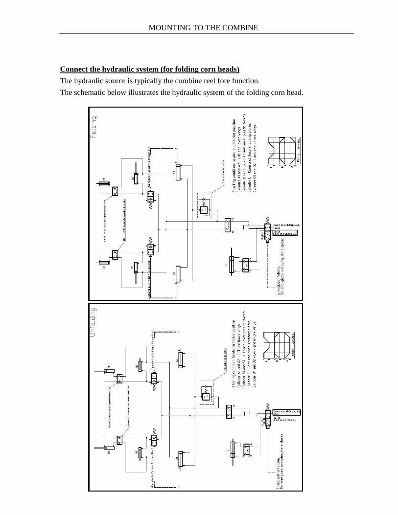
Connect the hydraulic system (for folding corn heads)
The hydraulic source is typically the combine reel fore function.
The schematic below illustrates the hydraulic system of the folding corn head.

MOUNTING TO THE COMBINE
29
The folding corn head hydraulic cylinders should operate in the following sequence:
1. The locking cylinders (D1, D2) must retract fully.
2. The rear divider cylinders (B1, B2) must extend fully.
3. The wing cylinders then fold the wings.
If the wing cylinders start before the other cylinders (D1, D2, B1, B2) reach the end
positions, then the pressure relief valve adjuster screw should be turned a half turn clockwise.
After this, re-attempt folding the header to check for proper operation.
Repeat these steps as necessary until the headers folds correctly.
Adjuster screw

RUN-IN PROCEDURE
30
6. RUN-IN PROCEDURE
A 30 minute “trial run” is suggested after the initial mounting.
Prior to the trial run, perform a full lubrication procedure as described in Section 11
"Maintenance and Lubrication”. Gearboxes are filled with lubricant at the factory but levels
should be checked before beginning the trial run.
Start the combine and momentarily engage the drive with the engine speed at low idle, If all
sounds well, run the corn head slowly. Avoid starting the drive at high engine speed as the
inertia load from acceleration can be 8-10 times more than the load from steady speed
operation. High-speed start-up may cause damage to the drive system and safety clutches.
After the slow speed start, increase the engine speed to a medium level and listen for
abnormal sounds. If no irregularity is observed, the engine speed can be increased to
maximum level for about 10 minutes.
When the trial run has been completed, shut off the engine, remove the key and check the
temperature of the gearboxes, bearings and drive units. No irregular overheating should
occur.

SETUP PROCEDURE AND ADJUSTMENT OF THE CORN HEAD
31
7. SETUP PROCEDURE AND ADJUSTMENT OF THE CORN HEAD
7.1. Frame
The corn head is provided with parking stands which must always be used when it is to be
disconnected from the combine. Before detaching the corn head from the combine, adjust
the parking stand position such that the distance between the ground and the lower support of
the corn head is about 30 cm (12 inches).
Adjust the stand position by removing and replacing the retaining pin, and re-installing the
hairpin.

SETUP PROCEDURE AND ADJUSTMENT OF THE CORN HEAD
32
7.2. Auger
The auger is driven through a torque-limiting clutch that can disengage excessive loads on
the drive. This clutch is located on the left-hand side, but an additional clutch is located on
the right hand side on larger corn heads.
In some conditions it may be necessary to change the speed of the auger. The driver sprocket
can be reversed to provide an alternate speed to suit field conditions.
High speed -16 tooth (factory)
Low speed - 14 tooth (alternate for lodged corn)
Rigid frame header: for adjusting the auger use the following screws - no. 3 and no. 6.
Gap between flighting and auger pan at minimum clearance
Check factory setting 1.0” – 1.25” (25 mm – 32 mm)
Check clearance at both ends of auger and adjust if necessary
5 4 6
3
1. Chain drive connecting link
2. Adjusting plate nuts
3. Auger raising / lowering with M12
nuts
4. Chain tensioner setting
5. Chain guidance
6. Auger fore/aft adjusting bolt.
1
2
1.0” – 1.25” (25 mm – 32 mm)

SETUP PROCEDURE AND ADJUSTMENT OF THE CORN HEAD
33
Augers will come standard from factory with full flighting installed
Options include fingers and paddles in place of full flighting
Fingers are recommended in very dry, fluffy corn where positive conveyance to the
feederhouse is needed
Paddles can be installed over the fingers if wrapping becomes problematic
Finger Type Full Flighting Type
7.3. Auger Timing:
7.3.1. Dual Auger Drive Time (Double Auger)
Flighting should be offset by 180° for paddles and fingers
To adjust:
Remove, rotate, and reinstall the RH drive shaft from the combine backshaft to the
desired position. Alternatively, remove auger drive chain and rotate auger to desired
position and reinstall chain.

SETUP PROCEDURE AND ADJUSTMENT OF THE CORN HEAD
34
7.3.2. Folding Corn Head Wing Auger Timing
Distance between flighting should be properly maintained to optimize feeding across
the wing joint
The distance between the flighting should be 18”-20”
Ensure the wing is engaging the center section when checking timing
To adjust timing, remove the jaw coupler on wing and rotate it in the appropriate
direction in the hex bore and reinstall

SETUP PROCEDURE AND ADJUSTMENT OF THE CORN HEAD
35
7.3. Input Gearbox Drive
The input gearboxes are connected by a double joint coupling drive or shaft (1) depending on
the combine. The gearbox assemblies (2) are selected to provide a nominal snapping unit
input speed of 550 rpm for each combine. Gearboxes can be exchanged as necessary.
See appropriate combine conversion document for complete instructions
The input gearbox drive does not require any additional adjustment
.
1
1
Double joint coupling
(all except Claas) Shaft-drive
(Claas)
2
1
2

SETUP PROCEDURE AND ADJUSTMENT OF THE CORN HEAD
36
7.4. Snapping units
7.4.1. Snapping rolls adjustment
Three important settings must be observed when installing or adjusting the snapping rolls.
7.4.1.1. Distance between snapping roll shafts
Adjust the shafts parallel to each other by setting 62 mm (2.45”) between the two bearing
housings as shown in the illustration below.
7.4.1.2. Labyrinth
Two sealed double ball bearings are used to support the spiral end of the snapping roll. The
bearings are protected by a labyrinth filled with grease. The labyrinth can be flushed by
adding grease through the grease nipple. The distance (0.5-1mm) is for reference only,
because design dimensions of the parts ensure the correct gap.

SETUP PROCEDURE AND ADJUSTMENT OF THE CORN HEAD
37
7.4.2. Snapping plate adjustment
The nominal factory setting is 27 mm (1-1/16”) at the front and 32 mm (1-1/4”) at the rear.
For proper operation, the snapping plate gap should be 5 mm (3/16”) tighter at the front than
at the rear. The in-cab snapping plate adjusting mechanism can change the gap to 9 mm
(5/16”) tighter and 10 mm (3/8”) wider than the nominal position. Set the mechanism as
follows:
Set the in-cab snapping plate adjusting mechanism to the minimum snapping plate gap.
Refer to the figure below. Adjust the fixed snapping plate (2) relative to the movable
snapping plate (1) to provide a gap of 18 mm (3/4”) at the front (dimension A) and 23
mm (15/16”) at the rear (dimension B) by loosening the retaining bolts (3). When the
adjustment is correct retighten the bolts. Repeat for all remaining row units.
In-cab operation should result in the nominal gap of 27 mm (1-1/16”) at the front and 32
mm (1-1/4”) at the rear in the mid-range of travel.
There is a tool (Snapping Plate Tool - PN 324048)
to help set the snapping plate clearance. This tool
can be ordered from your dealer. The Snapping
Plate Tool’s application is shown on the picture.
When adjusting the snapping plates, the brackets
that the snouts seat on can come out of alignment.

SETUP PROCEDURE AND ADJUSTMENT OF THE CORN HEAD
38
There is a tool (Snout Seating Tool – PN 324144)
that can be placed between the two brackets while
setting the snapping plate clearance so the snouts
align with the brackets after they are tightened
down. This tool can be ordered from your dealer
Periodically lubricate the top of the snapping plate indicator cable to prevent off-
season seizing of the cable.

SETUP PROCEDURE AND ADJUSTMENT OF THE CORN HEAD
39
7.4.3. Vine knife adjustment
The gap between the vine knives and the stalk rolls should not exceed 1 mm (.04”). This gap
should be set on one rib and all rib clearances should be checked by rotating the rolls to
ensure there is no interference. Adjustment is made by loosening the M-8 screws (3). Relief
holes are provided to make a fine adjustment.
There is a tool (Snapping Gauge Tool - PN 324124) to help set new knives on the snapping
roll. This tool can be ordered from your dealer. The Snapping Gauge Tool’s application is
shown on the picture below.
3
3
2
1

SETUP PROCEDURE AND ADJUSTMENT OF THE CORN HEAD
40
7.4.4. Gathering chain adjustment
The gathering chain tension is maintained automatically by an enclosed spring on the front
idler. A tool is provided to compress the spring for service.
How to use the gathering chain removal tool:
1. Install the gathering chain removal tool and attach it in the holes on the bottom of the
snapping unit frame.
2. Position the arm of the gathering chain removal tool into the carriage (circled lower left).3. Rotate the handle of the removal tool and lock it in place once tension on the
gathering chain is relieved.
4. Remove the gathering chain.
Gathering chain remover arm
carriage

SETUP PROCEDURE AND ADJUSTMENT OF THE CORN HEAD
41
Gathering Chain Lug Timing:
Fully Staggered Fully In-Phase (lugs lined
up)
One lug staggered
Least aggressive
Good conveyance
Most aggressive
Brings in most
trash/debris
Good for lodged corn
Good compromise
Factory setting
7.4.5. Gearbox timing and backlash adjustment
Snapping roll gear timing is done by visually aligning the hex shafts as shown below.
The backlash can be determined by rotating one gear relative to the other. There should be 1°
of free rotation between the gears. The backlash can be increased by adding gasket shims as
shown in the Parts Catalog.

SETUP PROCEDURE AND ADJUSTMENT OF THE CORN HEAD
42
7.5. Header Drive Shafts
The Walterscheid brand drive shafts require lubrication every 250 operating hours.
Remove the shaft annually and grease it according to the label instructions provided by the
shaft manufacturer on the shaft cover.
7.6. Clearance lights
Clearance lights must be changed from shipping to field position.
Simply remove four nuts on U-bolt clamps securing tube and rotate light 90 degrees

SETUP PROCEDURE AND ADJUSTMENT OF THE CORN HEAD
43
7.7. Plastic snout adjustment
Lower the combine feeder until the distance between the skid shoe of the snapping
unit and the ground is 8 cm (3-1/4”)
Snout support arms must be changed from shipping to field position. Remove the
cross bolt and reinstall in the desired position
Ensure bolt head is facing gathering chain
Fine tune snout adjustment with eye bolt until front of snout just touches the ground
Manufacturer and Distributor are not responsible for incorrect snout adjustment.

HARVESTING
44
8. HARVESTING
The corn head is ready for harvesting after completing the preceding instructions in this
manual, which refer to Mounting, Run-in, and Set-up and Adjustment Procedure.
Always be aware of the presence of the stalk chopper, if fitted, when harvesting.
The corn head should be operated only when in harvesting position and in proper
working condition.
Specified daily maintenance, correct settings and safe operation are required to ensure that the
stalk choppers operate properly and safely. Always consider possible circumstances where the
knife can impact stones or other foreign objects laying on the ground. Any such impact can
result in pieces separating from the hardened knife blade.
ALWAYS STAY CLEAR of the corn head while in operation. Bystanders should always be
at least 30 m (100 ft.) from the corn head while in operation.
1. After 1 hour of initial operation, stop the machine, remove the combine key, and
check the following:
a. Temperature of all gearboxes (maximum 60 degrees C or 170 F)
b. Loose parts or hardware
c. Tension of all chains
d. General visual inspection
If this inspection reveals any abnormality, determine the cause of the abnormality or
contact your dealer for assistance.
If the crop is severely laid or lodged it may be necessary to remove one or both of the
rubber ear savers from the rear of the snouts to improve feeding to the row units.

HARVESTING
45
8.1. Stalk chopper
The stalk chopper (1) cuts the stalks directly under the snapping rolls (2) with special knives.
The stalk chopper drive can be disengaged by turning the hex knob (3) 180 degrees.
Then chopper knives can be reversed when worn. When knife replacement is necessary
replace the bushings, bolts and nuts. Consult the parts manual for further information.
1
2
3

ROW SPACING ADJUSTMENT, MOUNTING TO ANOTHER TYPE OF COMBINE
46
9. ROW SPACING ADJUSTMENT
The row unit spacing must match the corn row spacing for optimum performance. This is of
greater importance with wider corn heads. Improper matching can result in premature wear
of the snapping roll front supports and the leading edge of the snapping plates. The row unit
spacing is set from the factory and is not designed to be adjusted afterwards.
10. MOUNTING TO ANOTHER TYPE OF COMBINE
The mounting kits for various combines are shown in the parts manual. Order the relevant
mounting kit from your dealer.
When mounting the corn head to another type of combine always use all of the protective
shields. Ensure that the lower latch attachment and drive connections are secure.

MAINTENANCE AND LUBRICATION
47
11. MAINTENANCE AND LUBRICATION
11.1. Frame
The frame of rigid corn headers does not require any special maintenance.
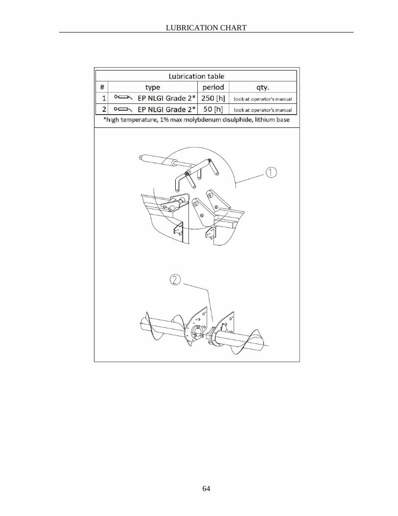
The folding mechanism of the folding corn head should be lubricated with EP NLGI Grade 2
or equivalent quality grease once a season or every 250 hours. Grease the fitting until grease
extrudes from the sides of the parts shown on the picture (marked with “A”).
11.2. Auger
The auger drive chain(s) should be lubricated every 50 hours, and the chain tension should be
checked daily. The chain tension is correct if the chain deflects 13-19 mm (0.5” – 0.75”) at
the position shown (“A”).
Clean debris under shielding every day!
A
A
A
A
MAINTENANCE AND LUBRICATION
48
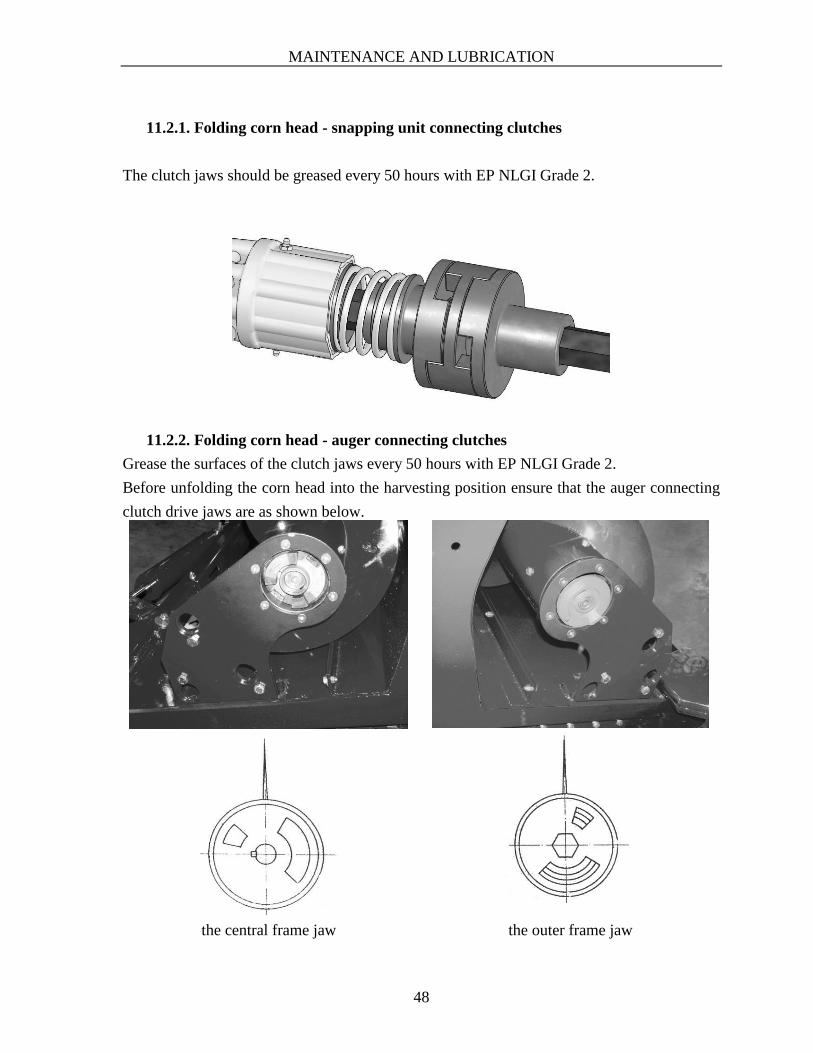
11.2.1. Folding corn head - snapping unit connecting clutches
The clutch jaws should be greased every 50 hours with EP NLGI Grade 2.
11.2.2. Folding corn head - auger connecting clutches
Grease the surfaces of the clutch jaws every 50 hours with EP NLGI Grade 2.
Before unfolding the corn head into the harvesting position ensure that the auger connecting
clutch drive jaws are as shown below.
the central frame jaw the outer frame jaw

MAINTENANCE AND LUBRICATION
49
11.3. INPUT GEARBOXES
SAE 80W-140 oil (0.9l) is used for lubrication. To check the oil level, remove the level plug
(1) with the corn head in harvesting position. Check the oil level annually or every 250 hours,
more often if leakage is detected. The drain and filling plugs (2) are on the main casting of
the gearbox, but filling can also be done through the level plug or breather ports.
Location of the oil checking bolts on the gearbox.
2
1
The "driver" gearbox is mounted in the upper
position for Lexion
The "driver" gearbox is
mounted in the lower position
for all others
1
1

MAINTENANCE AND LUBRICATION
50
The location of the breather depends on the final position of the gearbox. The breather should be placed in the cover hole above the oil level plug.
11.4. DRIVE COMPONENTS
11.4.1. U-joint shafts:
The U-joints should be greased every 250 hours.
Grease the sliding surfaces of the U-joint shafts and cross shafts annually.
11.4.2. Chain couplings, Slip clutches
Grease the Chain couplings every 250 hours
Grease the Slip clutches every 250 hours
“Driven” gearbox position, if the “driver” gearbox is
mounted in the upper position.
“Driven” gearbox position, if the “driver” gearbox is
mounted in the lower position.

MAINTENANCE AND LUBRICATION
51
11.5. SNAPPING UNIT
11.5.1. Gearboxes
Main gearbox Chopper gearbox
SAE 80W-140 oil - 0.26 kg (0.3 l)
EP-00 liquid grease 2.5 kg (2.5 l) -
Check frequency
Annually or every 250
hours whichever
comes first, or when
leakage detected
50 hours, or when
leakage detected
Inspect gearboxes daily to detect any leakage which may cause failure.
Snapping unit main gearbox:
Lubricant fill plug/dipstick
Lubricant drain plug

MAINTENANCE AND LUBRICATION
52
Stalk chopper gearbox:
To check lubricant levels:
- Lower corn head to the ground
- Unscrew the dipstick
- Wipe the dipstick, then replace it but do not screw it back in
- Wait, then remove the dipstick
- The lubricant level should be midway between the minimum and maximum
warning lines.
Snapping unit main gearbox
Lubricant drain Lubricant fill plug/dipstick
Lubricant fill plug/ dipstick
Lubricant fill plug/ dipstick
Chopper gearbox
min.
max.
min.
max.

MAINTENANCE AND LUBRICATION
53
Chopper knives
Check knife condition daily.
Never operate with damaged knives.
The radial clearance between the knife and bushing should not exceed 1 mm (.04”).
If clearance exceeds 1 mm (.04”), change both the knife and bushing.
Knives must be changed only in pairs because of the high rotational speed and balance
requirements.
The knife support bolts should be checked daily and kept tight.
Neither the Manufacturer nor Distributor assumes any responsibility for wear or
failure resulting from improper maintenance or lubrication.

MAINTENANCE AND LUBRICATION
54
11.5.2. Snapping roll
The front bearings are lubricated with EP NLGI Grade 2 and sealed on both sides by the
bearing manufacturer. A greased labyrinth is provided to protect the bearings. Grease the
front fitting every 250 operating hours, or once a season until grease extrudes from the
labyrinth. This will ensure flushing of the old grease and fully replacing it with new grease.
The locations of the front grease fitting of the snapping roll
Ensure that the snapping roll knife retaining bolts are kept tight at all times.
Check the clearance between snapping rolls knife edges
Factory setting (1 mm )

MAINTENANCE AND LUBRICATION
55
11.5.3. Gathering chain
Lubricate every 10 hours using synthetic or vegetable grease or oil.
Check daily for abnormal wear.
The corn head Pre-harvesting and Pre-delivery inspection checklists are at the end of
the operator’s manual.
Please verify the corn heads condition before the first running procedure following the
Pre-delivery inspection.
Please verify the corn heads condition before each harvesting following the
Pre-harvesting inspection.

ELECTRICAL SCHEMATICS
56
12. ELECTRICAL SCHEMATICS
12.1. JD electrical schematic

ELECTRICAL SCHEMATICS
57
12.2. CNH electrical schematic

ELECTRICAL SCHEMATICS
58
12.3. AGCO electrical schematic

ELECTRICAL SCHEMATICS
59
13.4. CLAAS Lexion electrical schematic

ELECTRICAL SCHEMATICS
60
13.5. CIH 1000 and 2000 series

TROUBLE SHOOTING
61
14. TROUBLE SHOOTING
14.1. A large quantity of ears builds up between the auger and feeder.
This can result from improper adjustment of the combine for corn harvesting operation,
including front feeder drum (rock retarder drum) position too low, threshing component
speed, concave clearance or angle of the feeder front face. Ensure that the combine is
adjusted for corn harvesting in accordance with the instructions and settings as recommended
in the combine operator’s manual.
14.2. In laid or lodged corn stalks, the stalks do not feed properly into the
snapping rolls.
Remove only 1 ear saver per row initially, then second ear saver only if necessary.
14.3. Row unit becomes plugged while harvesting laid or lodged cornstalks.
Check the tension of the gathering chain.
14.4. Stalks, grass or weeds wrap on the snapping roll.
Reduce gap of vine knives.
See “Set-up and Adjustment procedure” section 4.3.
14.5. Auger does not rotate.
Check setting of the auger drive torque limiting clutch.
See “Set-up and Adjustment procedure” section 4. 2.
14.6. Ears are broken or split in the auger.
Reduce the rotational speed of the auger using the optional sprocket.
See “Set-up and Adjustment Procedure”, section 4. 2.
14.7. Difficulty in keeping the corn head properly on the row.
Check that corn head row spacing matches the corn row spacing.

OFF-SEASON STORAGE OF YOUR CORN HEAD
62
15. OFF-SEASON STORAGE OF YOUR CORN HEAD
When harvesting is completed, thoroughly clean the corn head and remove all remaining
debris. Carefully inspect the corn head to ensure it will be in proper operating condition for
the next season. Repaint any paint-damaged area to prevent rusting. If this is not possible,
coat the unpainted area with rust protector. Repair or replace any damaged or missing parts,
including safety labels.
Lubricate the slides on the gathering chain front idlers. If possible, store the corn head in a
covered place. If this is not possible, remove the gathering chains, lubricate them and store in
a dry, covered area.
16. WARRANTY, SERVICE, SPARE PARTS ORDERING
Contact your dealer or distributor about issues concerning warranty or service.
The Manufacturer and Distributor assume no responsibility for failures, wear, or poor
performance resulting from improper maintenance, setting, storage or incorrect usage
of the corn head.
The warranty does not apply to wear items.
When ordering spare parts, always identify the corn head by:
type
serial number
part number as shown in the parts manual.

LUBRICATION CHART
63
17. LUBRICATION CHART
LUBRICATION CHART
64

PRE-DELIVERY & PRE-HARVESTING INSTRUCTIONS
65
18. PRE-DELIVERY & PRE-HARVESTING INSTRUCTIONS
18.1 Pre-delivery inspection
Please verify using the checkboxes below that the corn head is properly set up for harvesting.
Check the following and adjust if necessary.
✔ Item Reference
LIFTING BAR AND OTHER
PACKAGING ARE REMOVED
5.2. Other steps following the securing of the
adapter on the combine
7. SETUP PROCEDURE AND ADJUSTMENT OF
THE CORN HEAD
LOWER LATCHES PROPERLY
CONNECTED TO COMBINE FEEDER
5.1. Mounting the corn heads on the combine
CORN HEAD IS LEVEL 7.7. Plastic snout adjustment
DRIVE SHAFTS PROPERLY
CONNECTED TO COMBINE FEEDER
5.2. Other steps following the securing of the
adapter on the combine
ELECTRIC AND HYDRAULICS
PROPERLY CONNECTED
5.2. Other steps following the securing of the
adapter on the combine
15. Electrical schematics
SNAPPING PLATE ADJUSTMENT 7.4.2. Snapping plate adjustment
GATHERING CHAIN PROPERLY
TENSIONED
7.4.4. Gathering chain adjustment
DRIVE CHAINS PROPERLY
TENSIONED
11.2. Auger
SNOUTS AND DIVIDERS ADJUSTED
AND SECURED
7.7. Plastic snout adjustment
SAFETY SHIELDS SECURED -
GEARBOX LUBRICANT TO PROPER
LEVELS
12. INPUT GEARBOXES
14. SNAPPING UNIT
FOLDING/UNFOLDING OPERATION (IF
APPLICABLE)
5.2. Other steps following the securing of the
adapter on the combine
SNAPPING ROLL CLEARANCES 7.4.1. Snapping rolls adjustment
14.1.1. Snapping roll
ALL NUTS AND BOLTS ARE SECURED -
FREE ROTATION OF CHOPPER
KNIVES (IF APPLICABLE)
14.1. Gearboxes - Chopper knives
TEST RUN FOR 30 MINUTES -

PRE-DELIVERY & PRE-HARVESTING INSTRUCTIONS
66
18.1 Pre-Harvesting inspection
Please verify using the checkboxes below that the corn head is properly set up for harvesting.
Check the following and adjust if necessary.
✔ Item Reference
LOWER LATCHES PROPERLY
CONNECTED TO COMBINE FEEDER
5.1. Mounting the corn heads on the combine
CORN HEAD IS LEVEL 7.7. Plastic snout adjustment
DRIVE SHAFTS PROPERLY
CONNECTED TO COMBINE FEEDER
5.2. Other steps following the securing of the
adapter on the combine
ELECTRIC AND HYDRAULICS
PROPERLY CONNECTED
5.2. Other steps following the securing of the
adapter on the combine
15. Electrical schematics
SNAPPING PLATE ADJUSTMENT, IF
NEEDED CLEANING
7.4.2. Snapping plate adjustment
SNOUTS AND DIVIDERS ADJUSTED
AND SECURED
7.7. Plastic snout adjustment
FOLDING/UNFOLDING OPERATION (IF
APPLICABLE)
5.2. Other steps following the securing of the
adapter on the combine
ALL LUBRICANTS HAVE BEEN
CHECKED
11. MAINTENANCE AND LUBRICATION
12. INPUT GEARBOXES
13. DRIVE COMPONENTS
14. SNAPPING UNIT
TEST RUN (30 MINS) -

MacDon Industries Ltd.680 Moray StreetWinnipeg, ManitobaCanada R3J 3S3t. (204) 885-5590 f. (204) 832-7749
MacDon Brasil Agribusiness Ltda.Rua Grã Nicco, 113, sala 404, B. 04Mossunguê, Curitiba, ParanáCEP 81200-200 Brasilt. +55 (41) 2101-1713 f. +55 (41) 2101-1699
MacDon, Inc.10708 N. Pomona AvenueKansas City, MissouriUnited States 64153-1924t. (816) 891-7313 f. (816) 891-7323
LLC MacDon Russia Ltd.123317 Moscow, Russia10 Presnenskaya nab, Block CFloor 5, Office No. 534, Regus Business Centret. +7 495 775 6971 f. +7 495 967 7600
MacDon Australia Pty. Ltd.A.C.N. 079 393 721P.O. Box 103 Somerton, Victoria, AustraliaAustralia 3061t.+61 3 8301 1911 f.+61 3 8301 1912
MacDon Europe GmbHHagenauer Strasse 5965203 WiesbadenGermany
CUSTOMERSMacDon.com
DEALERSPortal.MacDon.com
Trademarks of products are the marks of theirrespective manufacturers and/or distributors.
Printed in Canada