Embed Size (px)
Citation preview
™
C-Start™ Smart SwitchInstallation Guide
WARNING: RISK OF ELECTRIC SHOCKThis product installation requires handling 120 volt wiring. Follow each step carefully. If any concerns handling wiring, hire a qualified electrician. Ensure all work meets applicable local and national codes.
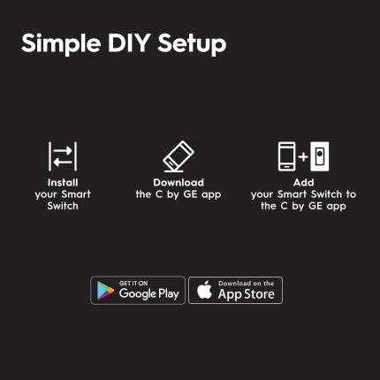
Downloadthe C by GE app
Installyour Smart
Switch
Addyour Smart Switch to
the C by GE app
Simple DIY Setup
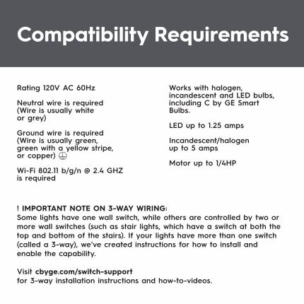
Rating 120V AC 60Hz
Neutral wire is required(Wire is usually white or grey)
Ground wire is required(Wire is usually green, green with a yellow stripe, or copper)
Wi-Fi 802.11 b/g/n @ 2.4 GHZ is required
Works with halogen, incandescent and LED bulbs, including C by GE Smart Bulbs.
LED up to 1.25 amps
Incandescent/halogen up to 5 amps
Motor up to 1/4HP
Compatibility Requirements
! IMPORTANT NOTE ON 3-WAY WIRING:Some lights have one wall switch, while others are controlled by two ormore wall switches (such as stair lights, which have a switch at both thetop and bottom of the stairs). If your lights have more than one switch(called a 3-way), we’ve created instructions for how to install andenable the capability.
Visit cbyge.com/switch-supportfor 3-way installation instructions and how-to-videos.
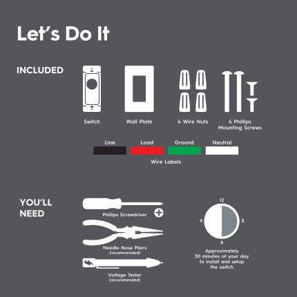
Let’s Do It
INCLUDED
YOU’LLNEED Phillips Screwdriver
Needle Nose Pliers(recommended) Approximately
30 minutes of your day to install and setup
the switch
12
6
39
Voltage Tester(recommended)
Switch
Wire Labels
Line Load Ground Neutral
Wall Plate 4 Wire Nuts 4 Phillips Mounting Screws

You Got This!
And we’re here to help.For in-depth instructional videosand a guided tour through the installation,go to cbyge.com/switch-support.
ON OFF
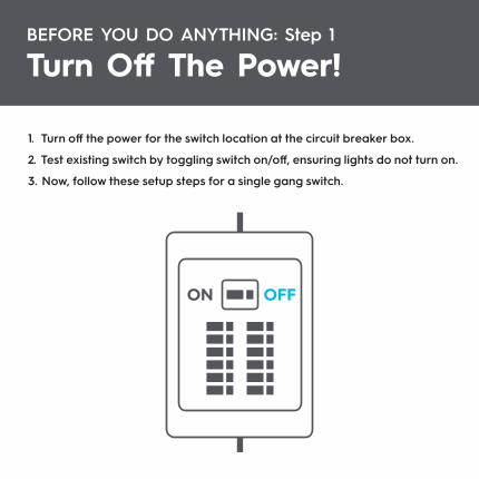
BEFORE YOU DO ANYTHING: Step 1
Turn Off The Power!
1. Turn off the power for the switch location at the circuit breaker box.
2. Test existing switch by toggling switch on/off, ensuring lights do not turn on.
3. Now, follow these setup steps for a single gang switch.
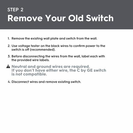
1. Remove the existing wall plate and switch from the wall.
2. Use voltage tester on the black wires to confirm power to the switch is off (recommended).
3. Before disconnecting the wires from the wall, label each with the provided wire labels.
Neutral and ground wires are required. If you don’t have either wire, the C by GE switch is not compatible.
4. Disconnect wires and remove existing switch.
STEP 2
Remove Your Old Switch
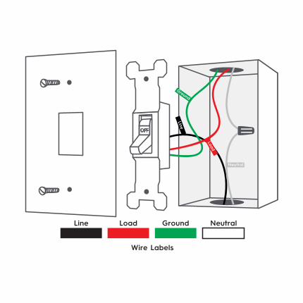
Wire Labels
Line Load Ground
Ground
Line
Load
Neutral
Neutral
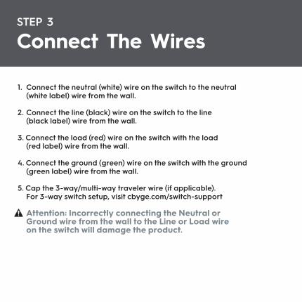
STEP 3
Connect The Wires
1. Connect the neutral (white) wire on the switch to the neutral (white label) wire from the wall.
2. Connect the line (black) wire on the switch to the line (black label) wire from the wall.
3. Connect the load (red) wire on the switch with the load (red label) wire from the wall.
4. Connect the ground (green) wire on the switch with the ground (green label) wire from the wall.
5. Cap the 3-way/multi-way traveler wire (if applicable). For 3-way switch setup, visit cbyge.com/switch-support
Attention: Incorrectly connecting the Neutral or Ground wire from the wall to the Line or Load wire on the switch will damage the product.
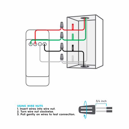
USING WIRE NUTS 1. Insert wires into wire nut.2. Turn wire nut clockwise.3. Pull gently on wires to test connection.
3/4 inch
Neutra
lGro
undLo
ad
Line
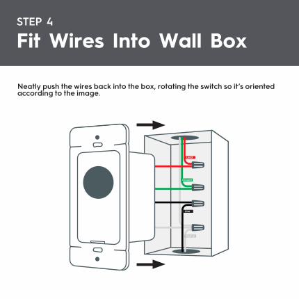
Neatly push the wires back into the box, rotating the switch so it’s orientedaccording to the image.
STEP 4
Fit Wires Into Wall Box
Load
Ground
Line
Neutral
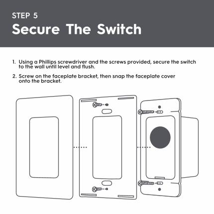
1. Using a Phillips screwdriver and the screws provided, secure the switch to the wall until level and flush.
2. Screw on the faceplate bracket, then snap the faceplate cover onto the bracket.
STEP 5
Secure The Switch
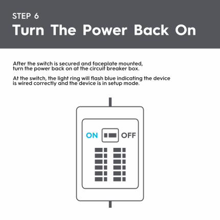
After the switch is secured and faceplate mounted,turn the power back on at the circuit breaker box.
At the switch, the light ring will flash blue indicating the deviceis wired correctly and the device is in setup mode.
STEP 6
Turn The Power Back On
ON OFF
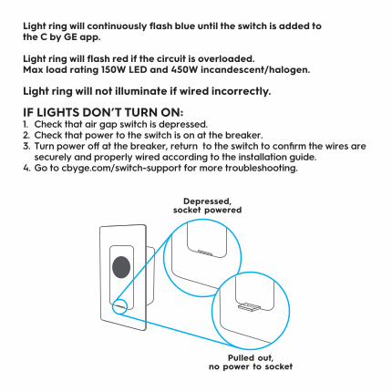
Depressed, socket powered
Pulled out, no power to socket
Light ring will continuously flash blue until the switch is added tothe C by GE app.
Light ring will flash red if the circuit is overloaded.Max load rating 150W LED and 450W incandescent/halogen.
Light ring will not illuminate if wired incorrectly.
IF LIGHTS DON’T TURN ON:1. Check that air gap switch is depressed. 2. Check that power to the switch is on at the breaker.3. Turn power off at the breaker, return to the switch to confirm the wires are securely and properly wired according to the installation guide.4. Go to cbyge.com/switch-support for more troubleshooting.
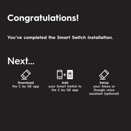
You’ve completed the Smart Switch installation.
Next...
Downloadthe C by GE app
Setupyour Alexa or Google voice
assistant (optional)
Addyour Smart Switch to
the C by GE app
Congratulations!
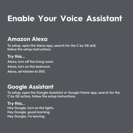
Amazon AlexaTo setup, open the Alexa app, search for the C by GE skill,follow the setup instructions.
Try this...Alexa, turn off the living room.Alexa, turn on the bedroom.Alexa, set kitchen to 50%.
Google AssistantTo setup, open the Google Assistant or Google Home app, search for theC by GE action, follow the setup instructions.
Try this...Hey Google, turn on the lights.Hey Google, good morning.Hey Google, I’m leaving.
Enable Your Voice Assistant
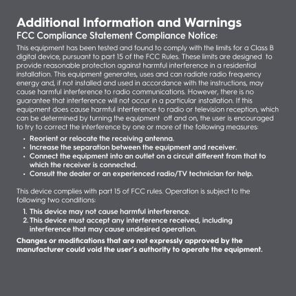
Additional Information and WarningsFCC Compliance Statement Compliance Notice:This equipment has been tested and found to comply with the limits for a Class B digital device, pursuant to part 15 of the FCC Rules. These limits are designed to provide reasonable protection against harmful interference in a residential installation. This equipment generates, uses and can radiate radio frequency energy and, if not installed and used in accordance with the instructions, may cause harmful interference to radio communications. However, there is no guarantee that interference will not occur in a particular installation. If this equipment does cause harmful interference to radio or television reception, which can be determined by turning the equipment off and on, the user is encouraged to try to correct the interference by one or more of the following measures: • Reorient or relocate the receiving antenna. • Increase the separation between the equipment and receiver. • Connect the equipment into an outlet on a circuit different from that to which the receiver is connected. • Consult the dealer or an experienced radio/TV technician for help.
This device complies with part 15 of FCC rules. Operation is subject to thefollowing two conditions: 1. This device may not cause harmful interference. 2. This device must accept any interference received, including interference that may cause undesired operation.Changes or modifications that are not expressly approved by the manufacturer could void the user’s authority to operate the equipment.
RF Exposure Information:This equipment complies with FCC radiation exposure limits set forth for an uncontrolled environment. In order to avoid the possibility of exceeding the FCC radio frequency exposure limits, human proximity to the antenna shall not be less than 8 inches during normal operation.
RF Exposure Statement:This equipment complies with IC RSS-102 radiation exposure limits set forth for an uncontrolled environment. This transmitter must be installed to provide a separation distance of at least 8 inches from all persons and must not be collocated or operating in conjunction with any other antenna or transmitter.
CAUTIONTo reduce the risk of overheating and possible damage to other equipment, do not install to control a receptacle or motor-operated appliance or transformer-supplied appliance.
For supply connections, use copper wire only rated at 75C.