Embed Size (px)
Citation preview

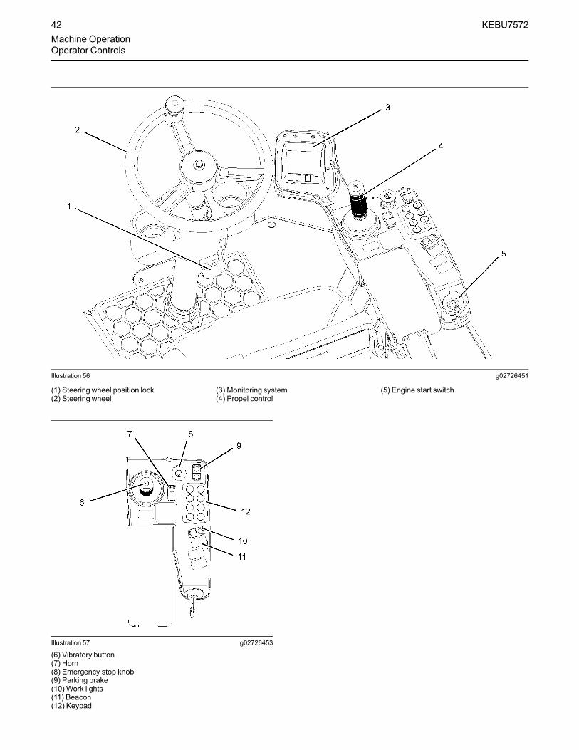
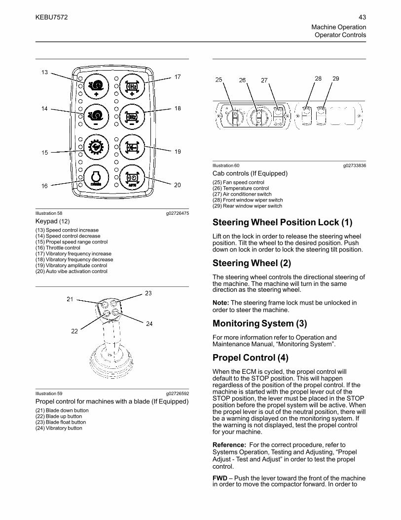
WEILER C110 VIBRATORY COMPACTOR
C110 VIBRATORY COMPACTOR
Operation and Maintenance Manual
July 2013S/N C110 - 1001 & UP
C110_o-m1_00Part # 22037

WEILER C110 VIBRATORY COMPACTOR
Dealer Name ___________________________ Customer Name ___________________Address ___________________________ Address ___________________City ___________________________ City ___________________State ___________________________ State ___________________ZIP/Post Code ___________________________ ZIP/Post Code ___________________Country ___________________________ Country ___________________
Phone ___________________________
MachineManufacture Date ___________________________Model C110 Vibratory Compactor Serial Number ___________________
Engine Engine Type CAT C4.4 with ACERT Serial Number ___________________
Arrangement #347-9582
Dealer Information Customer Information
Machine Identification Numbers

WEILER C110 VIBRATORY COMPACTOR
ATTENTION!
This manual consists of 6 separate sections, which provide machine operation and maintenance instructions and procedures. It is extremely important that the operator of this equipment reads and understands each section of this manual.
Section 1 - General InformationThis section consists of general information, machine specifications, and machine dimensions.
Section 2 - Power Unit OperationThis section consists of instructions for the operation and maintenance of the rear power unit and instructions for the operation of the front vibratory unit.
Section 3 - Water Spray System OperationThis section consists of instructions for the operation and maintenance of the drum and tire spray systems.
Section 4 - Vibratory Unit MaintenanceThis section consists of instructions for the maintenance of the front vibratory unit.
Section 5 - Maintenance - Combined ScheduleThis section consists of the combined maintenance instructions for sections 2, 3 and 5.
Section 6 - Receiving and Delivery ReportThis section consists of the receiving and delivery report.

This page intentionally left blank.

C110 VIBRATORY COMPACTOR
TABLE OF CONTENTS
General Information......................1-1Intended Use ............................................... 1-1
Introduction To This Manual ........................ 1-1
Machine Description .................................... 1-2
Specifications ............................................... 1-3
Engine Specifications ................................ 1-3
Engine Cooling System .......................... 1-3
Engine Fuel............................................. 1-3
Electrical Specifications ............................. 1-3
Batteries.................................................. 1-3
Alternator ................................................ 1-3
Starter ..................................................... 1-3
Performance Specifications ....................... 1-4
Speed ..................................................... 1-4
Machine System Capacity Specifications .. 1-4
System Capacities .................................. 1-4
Types of Lubricants ................................ 1-4
Dimensions .................................................. 1-5
Weights ........................................................ 1-5
Storage ...................................................... 1-6
Preparing for Storage ............................. 1-6
Removing from Storage.......................... 1-7
Power Unit Operation ...................2-1
Foreword.......................................................2-4
Safety Section
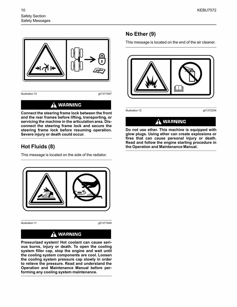
Safety Messages .......................................2-6
Additional Messages................................2-11
General Hazard Information ....................2-15
Crushing Prevention and Cutting Prevention................................................2-15
Burn Prevention .......................................2-15
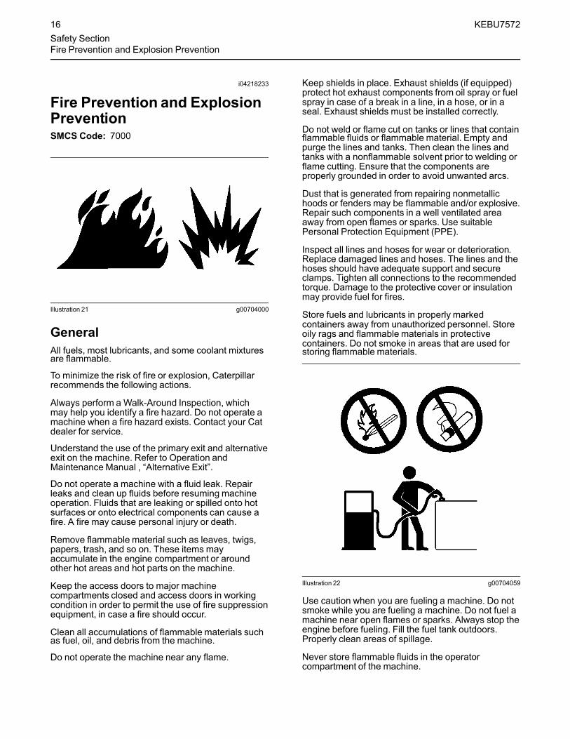
Fire Prevention and Explosion Prevention................................................2-16
Fire Safety ...............................................2-18
Fire Extinguisher Location .......................2-19
Tire Information........................................2-20
Electrical Storm Injury Prevention............2-20
High Pressure Fuel Lines ........................2-20
Before Starting Engine.............................2-21
Engine Starting ........................................2-22
Before Operation .....................................2-22
Visibility Information.................................2-22
Operation .................................................2-22
Engine Stopping ......................................2-23
Parking.....................................................2-23
Slope Operation.......................................2-23
Equipment Lowering with Engine Stopped .......................................2-24
Sound Information and Vibration Information................................2-25
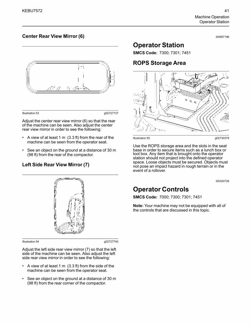
Operator Station ......................................2-27
Guards (Operator Protection) ..................2-27
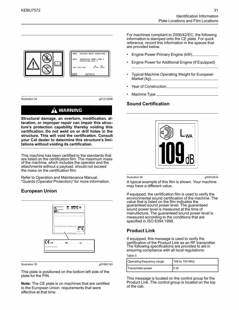
Identification Information.............................2-30
Operation Section .......................................2-34
Before Operation ........................................2-34
Machine Operation......................................2-36
Engine Starting ...........................................2-74
Parking........................................................2-76
Transportation Information..........................2-78
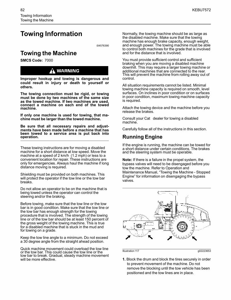
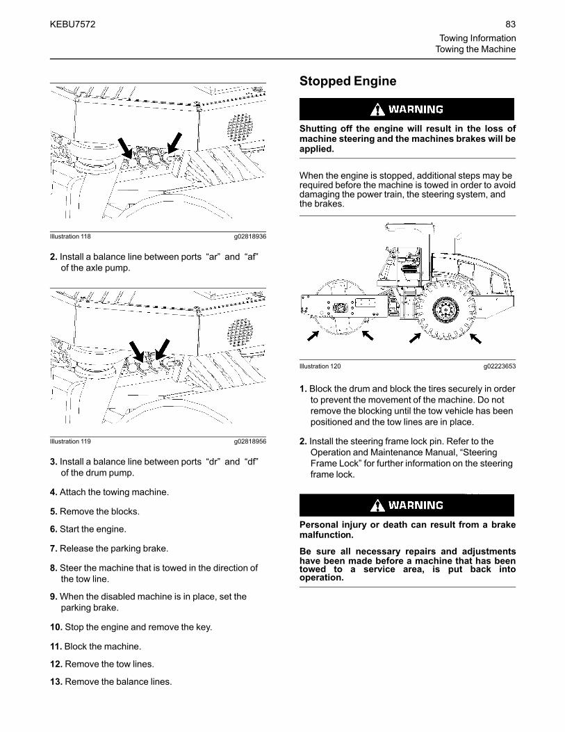
Towing Information .....................................2-82
Engine Starting (Alternate Methods)...........2-87
Maintenance Section ..................................2-90
Maintenance Access...................................2-90
Lubricant Viscosities and Refill Capacities .2-93
Maintenance Support................................2-100
Maintenance Interval Schedule .............2-102
Warranty Section ......................................2-150
Warranty Information ................................2-150
Reference Information Section .................2-151
Reference Materials..................................2-151
Table of Contents

WEILER C110 VIBRATORY COMPACTOR
Index Section ............................................2-153 Index ...................................................... 2-153
Water Spray Systems Operation. 3-1Controls ....................................................... 3-1
Water Spray - Drum................................... 3-1
Solution Spray - Tires ................................ 3-3
Drum Scrapers and Squeegee .................... 3-4
Vibrator Motor ..............................................3-4
Drum Scraper ............................................ 3-5
Drum Squeegee......................................... 3-5
Water Spray System - Drum...................... 3-6
Solution Spray System - Tires ................... 3-7
Machine Wash-down ................................. 3-8
Spray Down System - Electrical Schematic .3-1
Water Spray Schematic ............................... 3-2
Solution Spray Schematic ............................ 3-3
Vibratory Unit Maintenance ......... 4-1
Maintenance Section ..................................4-68
Capacities (Refill).....................................4-72
Drum Drive Planetary Oil Level - Check ..4-88
Drum Drive Planetary Oil Sample - Obtain ....................................................4-88
Eccentric Weight Housing Oil - Change ..................................................4-89
Eccentric Weight Housing Oil Level-Check .......................................3-92 Vibratory Frequency - Check ................... 3-92
Maintenance - Combined Schedule........................................ 5-1
Safety Messages ......................................... 5-1
General Information ..................................... 5-5
Welding Precautions.................................. 5-5
Lubrication Chart ......................................... 5-5
Maintenance Intervals .................................. 5-6
Maintenance Interval Schedule ................... 5-9
Machine - Grease ...................................... 5-10
Recommended Fluids..............................5-10
10 Service Hours or Daily Maintenance .....5-11
Drum Roller Bearing ................................5-11
Backup Alarm - Test ................................5-12
Cooling System Coolant Level - Check ...5-12
Engine Oil Level - Check .........................5-12
Hydraulic System Oil Level - Check.........5-12
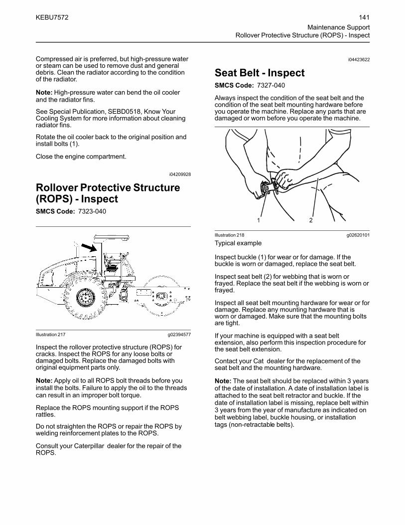
Seat Belt - Inspect ...................................5-12
50 Hour or Weekly Maintenance ................5-13
Water Spray Tank Strainer ......................5-13
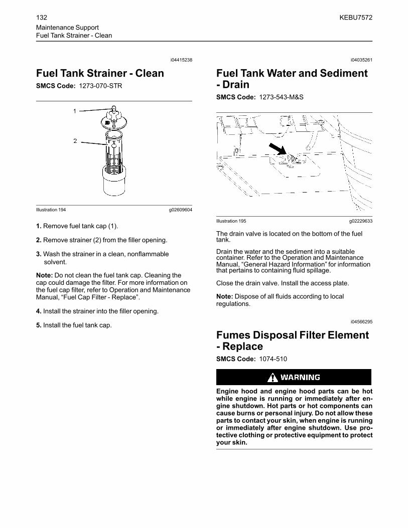
Fuel Tank Water and Sediment - Drain ...5-13
Steering Cylinder Ends - Lubricate ..........5-13
Ring Bearings - Lubricate ........................5-13
100 Hour Maintenance ...............................5-14
Overall Machine - Check..........................5-14
Safety Signs Maintenance .......................5-15
Tires - Check Pressure ............................5-15
Emergency Stop Knob - Test...................5-15
Initial 250 Service Hours Maintenance ......5-16
Axle Oil (Rear) - Change..........................5-16
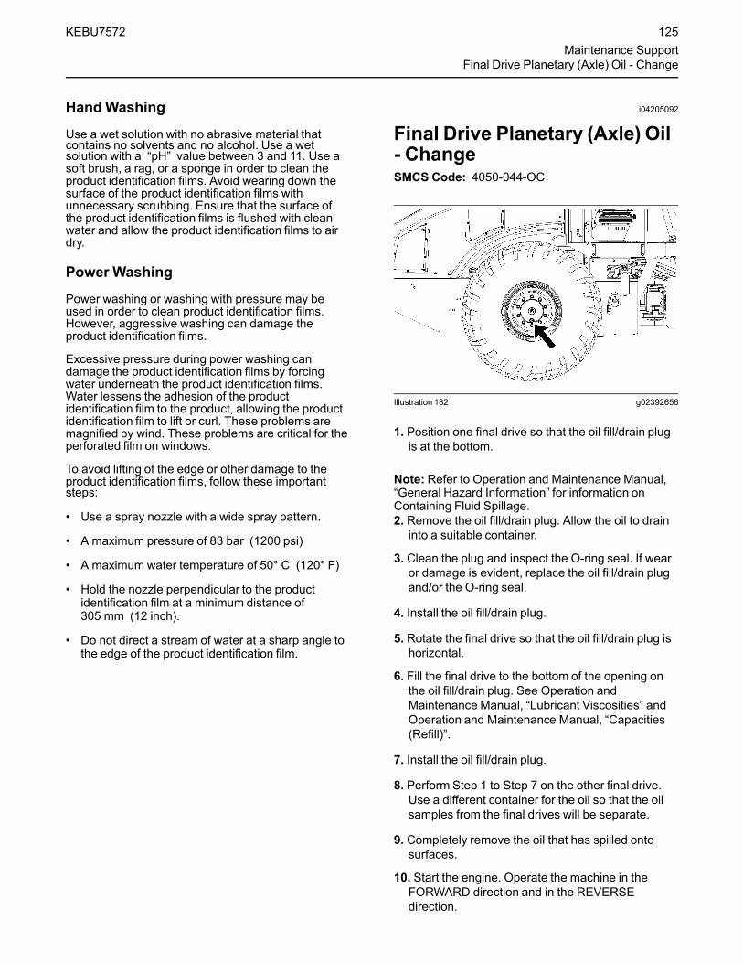
Final Drive Planetary (Axle) Oil - Change ..................................................5-16
Drum Drive Planetary Oil - Change .........5-16
Every 250 Service Hours Maintenance ......5-16
Cooling System Coolant Sample (Level 1) - Obtain .....................................5-16
Every 250 Service Hours or 3 Months Maintenance ...............................5-17
Axle Oil Level (Rear) - Check ..................5-17
Belts - Inspect/Adjust/Replace.................5-17
Engine Oil Sample - Obtain .....................5-17
Final Drive Planetary (Axle) Oil Level - Check...........................................5-17
Drum Drive Planetary Oil Level - Check...........................................5-17
Eccentric Weight Housing Oil Level - Check...........................................5-17
Table of Contents

C110 VIBRATORY COMPACTOR
Every 500 Service Hours Maintenance ..... 5-18
Fuel Tank Strainer - Clean....................... 5-18
Hood Latch - Adjust ................................. 5-18
Every 500 Service Hours or 6 Months Maintenance .............................. 5-19
Axle Oil Sample - Obtain ......................... 5-19
Engine Oil and Filter - Change ................ 5-19
Fuel System Primary Filter (Water Separator) - Replace.................... 5-19
Fuel System Secondary Filter - Replace . 5-19
Hydraulic System Oil Sample - Obtain .... 5-19
Parking Brake - Check............................. 5-19
Drum Drive Planetary Oil Sample - Obtain .................................................... 5-19
Every 1000 Service Hours Maintenance ... 5-20
Solution Spray Pump Filter - Replace...... 5-20
Drum Drive Planetary Oil - Change ......... 5-20
1000 Hours or 1 Year Maintenance ........... 5-21
Drum Vibration Motor - Check ................. 5-21
Drum Vibration Motor - Adjust ................. 5-21
Axle Oil (Rear) - Change ......................... 5-22
Cooling System Pressure Cap - Clean/Replace ....................................... 5-22
Final Drive Planetary (Axle) Oil - Change 5-22
Final Drive Planetary (Axle) Oil Sample - Obtain .................................................... 5-22
Hydraulic System Oil Filter - Replace ...... 5-22
Hydraulic Tank Breather - Replace.......... 5-23
Rollover Protective Structure (ROPS) - Inspect ..................................... 5-23
Vibratory Frequency - Check ................... 5-23
Every 2000 Service Hours Maintenance ... 5-24
Fuel Tank Cap Filter - Replace................ 5-24
Every 2000 Service Hours or 1 Year Maintenance ................................... 5-24
Fumes Disposal Filter Element - Replace ................................................. 5-24
Every Year Maintenance ........................... 5-24
Cooling System Coolant Sample (Level 2) - Obtain ..................................... 5-24
Every 3000 Service Hours Maintenance .... 5-24
Steering Column Spline (HMU Steering) - Lubricate......................5-24
Every 3000 Service Hours or 18 Months Maintenance ............................ 5-25
Hydraulic System Oil - Change................ 5-25
Every 3000 Service Hours or 2 Years Maintenance ................................. 5-25
Cooling System Water Temperature Regulator - Replace ........... 5-25
Every 3000 Service Hours or 3 Years Maintenance ................................. 5-25
Eccentric Weight Housing Oil - Change ..5-25
Every 6000 Service Hours or 3 Years Maintenance ................................. 5-26
Cooling System Coolant Extender (ELC) - Add .............................. 5-26
Every 12000 Service Hours or 6 Years ...... 5-26
Cooling System Coolant (ELC) - Change 5-26
When Required Maintenance .................... 5-27
Water Spray (Drum) Nozzles - Clean ...... 5-27
Solution Spray (Tires) Nozzles - Clean....5-28
Battery - Clean/Check.............................. 5-29
Battery - Recycle ..................................... 5-29
Battery or Battery Cable - Inspect/Replace..................................... 5-29
Cab Air Filter - Clean/Replace ................. 5-29
Engine Air Filter Primary Element - Clean/Replace ....................................... 5-29
Engine Air Filter Secondary Element - Replace ................................................. 5-29
Film (Product Identification) - Clean ........ 5-30
Fuel System - Prime ................................ 5-30
Fuses - Replace....................................... 5-30
Oil Filter - Inspect..................................... 5-30
Radiator Core - Clean.............................. 5-30
Table of Contents

WEILER C110 VIBRATORY COMPACTOR
Tire Spacing - Change............................. 5-30
Wheel Nuts - Tighten ............................... 5-31
Window Washer Reservoir - Fill .............. 5-31
Window Wiper - Inspect/Replace.............5-31
Windows - Clean......................................5-31
Receiving and Delivery Report ... 6-1
Table of Contents

WEILER C110 VIBRATORY COMPACTOR
Gen
eral
Info
rmat
ion
1
SECTION 1: GENERAL INFORMATION
INTENDED USE
The Vibratory Compactor is a vibratory, ride-on hydrostatic driven machine equipped with a full width front steel roller for compaction of crushed stone aggregate sub-bases and asphalt paved surfaces.
Always use the machine in accordance with the instructions contained in this Operation and Maintenance Manual, safety signs on the machine, and other material provided by Weiler.
Proper maintenance and repair is essential for safety, and for efficient operation of the machine. Do not use the machine if it is not in suitable operating condition.
INTRODUCTION TO THIS MANUAL
This manual provides correct procedures for operating and maintaining your machine.
Read this manual carefully before operating the machine and keep it in the manual holder on the machine for future reference. If at any time a question arises concerning the equipment or procedures, contact an authorized Weiler dealer. Factory trained personnel, genuine replacement parts and the necessary equipment are available for all service requirements.
This machine has been designed and built to give outstanding performance and ease of operation under a variety of conditions. To maintain your machine and ensure trouble free operation, the routine maintenance as specified in this manual must be carried out at the recommended intervals. Prior to delivery, the machine was carefully inspected at the factory and by your dealer.
All information in this manual is based on the latest information available at time of publication. Dimensions and weight are approximate and the illustrations may not show the equipment in standard configuration. Your machine may have product improvements and features not yet contained in this manual.
Weiler reserves the right to make changes at any time without notice or obligation.
1-1Intended Use

1
WEILER C110 VIBRATORY COMPACTOR
Gen
eral Info
rmatio
n1
MACHINE DESCRIPTION
The compactor is a vibratory compaction roller with a full width steel roller on the front that can compact paving surfaces for many applications including city streets, parking lots, sidewalks and driveways.
The compactor is equipped with a CAT C4.4 with ACERT, 131 hp (97.6 kw) diesel engine. Power is transmitted to the roller by a variable speed hydrostatic pump through a two speed hydrostatic motor. Shifting is accomplished by using a switch on the operator’s console for the two speed motor. Steering is accomplished by a hydraulically articulated front smooth-drum roller. The roller is equipped with a full width scraper and sprayer for keeping roller free of asphalt. The tires are equipped with sprayers for keeping the tires free of asphalt.
The air ride suspension seat positions the operator for visibility, control and comfort. The operator has an excellent view of the roller and sides of the machine.Two side mirrors and one rear-view mirror are provided for indirect operator visibility of the rear of the machine. The mirrors are individually adjustable for rearward visibility to monitor the work area for obstructions and locations of ground workers.
For quick reference, record the serial numbers in the front of this book on the customer information page.
The Weiler identification plate (1) is located on the left hand side of the seat base, beside the storage area for the electronic display vandal cover.
The CAT identification plate (2) is located on the left hand side of the machine, behind the tire solution sprayer tank.
1
2
1-2 Machine Description

WEILER C110 VIBRATORY COMPACTOR
Gen
eral
Info
rmat
ion
1
SPECIFICATIONS
The specifications provided in this section are applicable to the Vibratory Compactor. Included in this section are machine weights, dimensions and performance.
Engine SpecificationsEngine . . . . . . . . . . . . . . . . . . . . . . . . . . . . . . . . . . . . . . . . . Caterpillar C4.4 Tier IVi with ACERT
Arrangement No. . . . . . . . . . . . . . . . . . . . . . . . . . . . . . . . . . . . . . . . . . . . . . . . . . . . . . 347–9582
Power . . . . . . . . . . . . . . . . . . . . . . . . . . . . . . . . . . . . . . . . . . . . . . . . . . . . . . . . .131 hp (97.6 kW)
Engine Cooling SystemType . . . . . . . . . . . . . . . . . . . . . . . . . . . . . . . . . . . . . . . . . . . . . . . . . . . . . . . . . . . . . . . Liquid Cooled
Engine FuelType Used . . . . . . . . . . . . . . . . . . . . . . . . . . . . . . . . . . . . . .Ultra-Low Sulfur Diesel Fuel (15 ppm)
Fuel Capacity. . . . . . . . . . . . . . . . . . . . . . . . . . . . . . . . . . . . . . . . . . . . . . . . . . . . . . . . 53 gal (200 L)
Electrical Specifications
BatteriesNumber Per Machine . . . . . . . . . . . . . . . . . . . . . . . . . . . . . . . . . . . . . .Two 12 V batteries in series
Cold Cranking Amps, each . . . . . . . . . . . . . . . . . . . . . . . . . . . . . . . . . . . . . . . . . . . . . . . . . 750 CCA
System Voltage . . . . . . . . . . . . . . . . . . . . . . . . . . . . . . . . . . . . . . . . . . . . . . . . . . . . . . . . . . . . . . 24 V
AlternatorType and Voltage. . . . . . . . . . . . . . . . . . . . . . . . . . . . . . . . . . . . . . . . . . . . . . . . . . . . . . . . . CAT, 24V
Output Amperage . . . . . . . . . . . . . . . . . . . . . . . . . . . . . . . . . . . . . . . . . . . . . . . . . . . . . . . .100 Amps
StarterType and Voltage. . . . . . . . . . . . . . . . . . . . . . . . . . . . . . . . . . . . . . . . . . . . . . . . . . . . . . . . . CAT, 24V
Coolant. . . . . . . . . . . . . . . . . . . . . . . . . . . . . . . . . . . . . . . . . . . Extended Life (ELC) CAT EC-1 Spec
1-3Specifications
1
WEILER C110 VIBRATORY COMPACTOR
Gen
eral Info
rmatio
n1
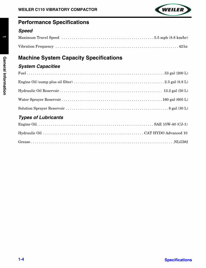
Performance Specifications
SpeedMaximum Travel Speed . . . . . . . . . . . . . . . . . . . . . . . . . . . . . . . . . . . . . . . . . . . . . 5.5 mph (8.8 km/hr)
Vibration Frequency . . . . . . . . . . . . . . . . . . . . . . . . . . . . . . . . . . . . . . . . . . . . . . . . . . . . . . . . . . . . 42 hz
Machine System Capacity Specifications
System Capacities Fuel . . . . . . . . . . . . . . . . . . . . . . . . . . . . . . . . . . . . . . . . . . . . . . . . . . . . . . . . . . . . . . . . . . . 53 gal (200 L)
Engine Oil (sump plus oil filter) . . . . . . . . . . . . . . . . . . . . . . . . . . . . . . . . . . . . . . . . . . . . 2.3 gal (8.8 L)
Hydraulic Oil Reservoir . . . . . . . . . . . . . . . . . . . . . . . . . . . . . . . . . . . . . . . . . . . . . . . . . . 13.2 gal (50 L)
Water Sprayer Reservoir . . . . . . . . . . . . . . . . . . . . . . . . . . . . . . . . . . . . . . . . . . . . . . . . . 160 gal (605 L)
Solution Sprayer Reservoir . . . . . . . . . . . . . . . . . . . . . . . . . . . . . . . . . . . . . . . . . . . . . . . . . . 8 gal (30 L)
Types of LubricantsEngine Oil. . . . . . . . . . . . . . . . . . . . . . . . . . . . . . . . . . . . . . . . . . . . . . . . . . . . . . . . . SAE 15W-40 (CJ-1)
Hydraulic Oil . . . . . . . . . . . . . . . . . . . . . . . . . . . . . . . . . . . . . . . . . . . . . . . . . CAT HYDO Advanced 10
Grease . . . . . . . . . . . . . . . . . . . . . . . . . . . . . . . . . . . . . . . . . . . . . . . . . . . . . . . . . . . . . . . . . . . . . .NLGI#2
1-4 Specifications

WEILER C110 VIBRATORY COMPACTOR
Gen
eral
Info
rmat
ion
1
DIMENSIONS
WEIGHTS
Description C110
A. Height 120” (305 cm)B. Length 226” (574 cm)C. Width 91” (231 cm)D. Ground Clearance 18” (46 cm)E. Wheel Base 114” (289 cm)F. Drum Diameter 51” (129 cm)G. Drum Width 84” (213 cm)H. Drum Oscillation (each way) 15°I. Maximum Turn Angle (each way) 34°
Inside Turning Radius 13’ 9” (419 cm)J. Tire Size 16.9-30 6 ply
Weight, base, Cab 19105 lb (8665 kg)Weight, base, ROPS 18320 lb (8310 kg)
Weight, w/ Water, Cab 20625 lb (9355 kg)Weight, w/ Water, ROPS 19840 lb (9000 kg)
1-5Dimensions
1
WEILER C110 VIBRATORY COMPACTOR
Gen
eral Info
rmatio
n1
Storage
Preparing for Storage
• Store machine inside or under cover.
• Clean off foreign material and wash machine. Repaint bare metal to inhibit rust.
NOTICE: Machine controls and electrical/electronic devices are not rated to withstand high pressure water and high temperature power washers. Water intrusion will likely cause malfunction or damage to any devices hit directly by the water spray. Keep pressure washer stream away from machine controls and electrical/electronic devices. Compressed air can also push moisture through some connector and component seals. Do not point air nozzle directly at seal areas.
• Repair or replace worn or broken parts or damaged decals.
• Refer to the Caterpillar Engine Operation and Maintenance Manual supplied with the machinefor engine storage instructions.
• Check engine coolant anti-freeze level to ensure radiator and engine are protected to the lowestfreezing temperature encountered.
• Disconnect battery with battery disconnect switch or remove battery for inside storage. Checkfluid level and charge fully; recheck every 30 days and charge if necessary.
• Coat exposed cylinder rods with grease or rust preventative oil.
• If freezing temperatures will be encountered, drain the water spray system.
• Drain water tank.
• Drain the supply lines and spray bars. Use low pressure compressed air to ensure completeremoval of water.
• Drain all water from the water pump filter.
• Drain all water from both water pumps by briefly turning on pumps.
NOTICE: Failure to completely drain all water from the water spray system may result in component damage if freezing occurs.
• Drain solution from tire sprayer tanks.
• Drain the supply lines.
• Drain all solution from the tire sprayer pump filter.
• Drain all solution from solution pump by briefly turning on pump.
• Fill the fuel tank to reduce moisture condensation while in storage.
• If freezing temperatures will be encountered, drain all water ballast from the drum.
Use Shutdown Procedure when preparing machine for storage. Refer to Shutdown Procedure for instructions.
1-6 Weights

WEILER C110 VIBRATORY COMPACTOR
Gen
eral
Info
rmat
ion
1
Removing from Storage• Remove all protective coverings.
• Drain any water and sediment from fuel tank that may have built up during storage. Fill fuel tank.
• Check battery fluid level. Charge battery and install in machine if removed or reconnect cables.
• Refer to the Engine Operation Manual instructions for restoring engine to operation.
NOTE: Disable fuel system and crank engine to provide crankshaft lubrication before allowing engine to start.
1-7Weights

This page intentionally left blank.
WEILER C110 VIBRATORY COMPACTOR
Po
wer
Un
it O
per
atio
n2
SECTION 2: POWER UNIT OPERATION
The following information is from the “Caterpillar CS54B, CP54B and CS64B Vibratory Soil Compactor Operation and Maintenance Manual”, part number KEBU7572-03 April 2013.
2-1

1
WEILER C110 VIBRATORY COMPACTOR
Po
wer U
nit O
peratio
n2
2-2
WEILER C110 VIBRATORY COMPACTOR
Po
wer
Un
it O
per
atio
n2
2-3

1
WEILER C110 VIBRATORY COMPACTOR
Po
wer U
nit O
peratio
n2
2-4

WEILER C110 VIBRATORY COMPACTOR
Po
wer
Un
it O
per
atio
n2
2-5

1
WEILER C110 VIBRATORY COMPACTOR
Po
wer U
nit O
peratio
n2
2-6

WEILER C110 VIBRATORY COMPACTOR
Po
wer
Un
it O
per
atio
n2
2-7

1
WEILER C110 VIBRATORY COMPACTOR
Po
wer U
nit O
peratio
n2
2-8
WEILER C110 VIBRATORY COMPACTOR
Po
wer
Un
it O
per
atio
n2
2-9

1
WEILER C110 VIBRATORY COMPACTOR
Po
wer U
nit O
peratio
n2
2-10
WEILER C110 VIBRATORY COMPACTOR
Po
wer
Un
it O
per
atio
n2
2-11

1
WEILER C110 VIBRATORY COMPACTOR
Po
wer U
nit O
peratio
n2
2-12

WEILER C110 VIBRATORY COMPACTOR
Po
wer
Un
it O
per
atio
n2
2-13

1
WEILER C110 VIBRATORY COMPACTOR
Po
wer U
nit O
peratio
n2
2-14

WEILER C110 VIBRATORY COMPACTOR
Po
wer
Un
it O
per
atio
n2
2-15

1
WEILER C110 VIBRATORY COMPACTOR
Po
wer U
nit O
peratio
n2
2-16
WEILER C110 VIBRATORY COMPACTOR
Po
wer
Un
it O
per
atio
n2
2-17

1
WEILER C110 VIBRATORY COMPACTOR
Po
wer U
nit O
peratio
n2
2-18

WEILER C110 VIBRATORY COMPACTOR
Po
wer
Un
it O
per
atio
n2
2-19

1
WEILER C110 VIBRATORY COMPACTOR
Po
wer U
nit O
peratio
n2
2-20

WEILER C110 VIBRATORY COMPACTOR
Po
wer
Un
it O
per
atio
n2
2-21

1
WEILER C110 VIBRATORY COMPACTOR
Po
wer U
nit O
peratio
n2
2-22

WEILER C110 VIBRATORY COMPACTOR
Po
wer
Un
it O
per
atio
n2
2-23

1
WEILER C110 VIBRATORY COMPACTOR
Po
wer U
nit O
peratio
n2
2-24

WEILER C110 VIBRATORY COMPACTOR
Po
wer
Un
it O
per
atio
n2
2-25

1
WEILER C110 VIBRATORY COMPACTOR
Po
wer U
nit O
peratio
n2
2-26

WEILER C110 VIBRATORY COMPACTOR
Po
wer
Un
it O
per
atio
n2
2-27

1
WEILER C110 VIBRATORY COMPACTOR
Po
wer U
nit O
peratio
n2
2-28

WEILER C110 VIBRATORY COMPACTOR
Po
wer
Un
it O
per
atio
n2
2-29

1
WEILER C110 VIBRATORY COMPACTOR
Po
wer U
nit O
peratio
n2
2-30
WEILER C110 VIBRATORY COMPACTOR
Po
wer
Un
it O
per
atio
n2
2-31

1
WEILER C110 VIBRATORY COMPACTOR
Po
wer U
nit O
peratio
n2
2-32

WEILER C110 VIBRATORY COMPACTOR
Po
wer
Un
it O
per
atio
n2
2-33

1
WEILER C110 VIBRATORY COMPACTOR
Po
wer U
nit O
peratio
n2
2-34

WEILER C110 VIBRATORY COMPACTOR
Po
wer
Un
it O
per
atio
n2
2-35

1
WEILER C110 VIBRATORY COMPACTOR
Po
wer U
nit O
peratio
n2
2-36

WEILER C110 VIBRATORY COMPACTOR
Po
wer
Un
it O
per
atio
n2
2-37

1
WEILER C110 VIBRATORY COMPACTOR
Po
wer U
nit O
peratio
n2
2-38

WEILER C110 VIBRATORY COMPACTOR
Po
wer
Un
it O
per
atio
n2
2-39
1
WEILER C110 VIBRATORY COMPACTOR
Po
wer U
nit O
peratio
n2
2-40
WEILER C110 VIBRATORY COMPACTOR
Po
wer
Un
it O
per
atio
n2
2-41
1
WEILER C110 VIBRATORY COMPACTOR
Po
wer U
nit O
peratio
n2
2-42

WEILER C110 VIBRATORY COMPACTOR
Po
wer
Un
it O
per
atio
n2
2-43

1
WEILER C110 VIBRATORY COMPACTOR
Po
wer U
nit O
peratio
n2
2-44
WEILER C110 VIBRATORY COMPACTOR
Po
wer
Un
it O
per
atio
n2
2-45
1
WEILER C110 VIBRATORY COMPACTOR
Po
wer U
nit O
peratio
n2
2-46

WEILER C110 VIBRATORY COMPACTOR
Po
wer
Un
it O
per
atio
n2
2-47

1
WEILER C110 VIBRATORY COMPACTOR
Po
wer U
nit O
peratio
n2
2-48

WEILER C110 VIBRATORY COMPACTOR
Po
wer
Un
it O
per
atio
n2
2-49
1
WEILER C110 VIBRATORY COMPACTOR
Po
wer U
nit O
peratio
n2
2-50
WEILER C110 VIBRATORY COMPACTOR
Po
wer
Un
it O
per
atio
n2
2-51

1
WEILER C110 VIBRATORY COMPACTOR
Po
wer U
nit O
peratio
n2
2-52

WEILER C110 VIBRATORY COMPACTOR
Po
wer
Un
it O
per
atio
n2
2-53

1
WEILER C110 VIBRATORY COMPACTOR
Po
wer U
nit O
peratio
n2
2-54

WEILER C110 VIBRATORY COMPACTOR
Po
wer
Un
it O
per
atio
n2
2-55

1
WEILER C110 VIBRATORY COMPACTOR
Po
wer U
nit O
peratio
n2
2-56

WEILER C110 VIBRATORY COMPACTOR
Po
wer
Un
it O
per
atio
n2
2-57

1
WEILER C110 VIBRATORY COMPACTOR
Po
wer U
nit O
peratio
n2
2-58

WEILER C110 VIBRATORY COMPACTOR
Po
wer
Un
it O
per
atio
n2
2-59

1
WEILER C110 VIBRATORY COMPACTOR
Po
wer U
nit O
peratio
n2
2-60

WEILER C110 VIBRATORY COMPACTOR
Po
wer
Un
it O
per
atio
n2
2-61

1
WEILER C110 VIBRATORY COMPACTOR
Po
wer U
nit O
peratio
n2
2-62

WEILER C110 VIBRATORY COMPACTOR
Po
wer
Un
it O
per
atio
n2
2-63

1
WEILER C110 VIBRATORY COMPACTOR
Po
wer U
nit O
peratio
n2
2-64

WEILER C110 VIBRATORY COMPACTOR
Po
wer
Un
it O
per
atio
n2
2-65
1
WEILER C110 VIBRATORY COMPACTOR
Po
wer U
nit O
peratio
n2
2-66
WEILER C110 VIBRATORY COMPACTOR
Po
wer
Un
it O
per
atio
n2
2-67

1
WEILER C110 VIBRATORY COMPACTOR
Po
wer U
nit O
peratio
n2
2-68
WEILER C110 VIBRATORY COMPACTOR
Po
wer
Un
it O
per
atio
n2
2-69
1
WEILER C110 VIBRATORY COMPACTOR
Po
wer U
nit O
peratio
n2
2-70

WEILER C110 VIBRATORY COMPACTOR
Po
wer
Un
it O
per
atio
n2
2-71

1
WEILER C110 VIBRATORY COMPACTOR
Po
wer U
nit O
peratio
n2
2-72

WEILER C110 VIBRATORY COMPACTOR
Po
wer
Un
it O
per
atio
n2
2-73

1
WEILER C110 VIBRATORY COMPACTOR
Po
wer U
nit O
peratio
n2
2-74

WEILER C110 VIBRATORY COMPACTOR
Po
wer
Un
it O
per
atio
n2
2-75

1
WEILER C110 VIBRATORY COMPACTOR
Po
wer U
nit O
peratio
n2
2-76

WEILER C110 VIBRATORY COMPACTOR
Po
wer
Un
it O
per
atio
n2
2-77

1
WEILER C110 VIBRATORY COMPACTOR
Po
wer U
nit O
peratio
n2
2-78

WEILER C110 VIBRATORY COMPACTOR
Po
wer
Un
it O
per
atio
n2
2-79

1
WEILER C110 VIBRATORY COMPACTOR
Po
wer U
nit O
peratio
n2
2-80

WEILER C110 VIBRATORY COMPACTOR
Po
wer
Un
it O
per
atio
n2
2-81

1
WEILER C110 VIBRATORY COMPACTOR
Po
wer U
nit O
peratio
n2
2-82

WEILER C110 VIBRATORY COMPACTOR
Po
wer
Un
it O
per
atio
n2
2-83

1
WEILER C110 VIBRATORY COMPACTOR
Po
wer U
nit O
peratio
n2
2-84

WEILER C110 VIBRATORY COMPACTOR
Po
wer
Un
it O
per
atio
n2
2-85

1
WEILER C110 VIBRATORY COMPACTOR
Po
wer U
nit O
peratio
n2
2-86

WEILER C110 VIBRATORY COMPACTOR
Po
wer
Un
it O
per
atio
n2
2-87

1
WEILER C110 VIBRATORY COMPACTOR
Po
wer U
nit O
peratio
n2
2-88

WEILER C110 VIBRATORY COMPACTOR
Po
wer
Un
it O
per
atio
n2
2-89
1
WEILER C110 VIBRATORY COMPACTOR
Po
wer U
nit O
peratio
n2
2-90
WEILER C110 VIBRATORY COMPACTOR
Po
wer
Un
it O
per
atio
n2
2-91

1
WEILER C110 VIBRATORY COMPACTOR
Po
wer U
nit O
peratio
n2
2-92

WEILER C110 VIBRATORY COMPACTOR
Po
wer
Un
it O
per
atio
n2
2-93

1
WEILER C110 VIBRATORY COMPACTOR
Po
wer U
nit O
peratio
n2
2-94

WEILER C110 VIBRATORY COMPACTOR
Po
wer
Un
it O
per
atio
n2
2-95

1
WEILER C110 VIBRATORY COMPACTOR
Po
wer U
nit O
peratio
n2
2-96

WEILER C110 VIBRATORY COMPACTOR
Po
wer
Un
it O
per
atio
n2
2-97

1
WEILER C110 VIBRATORY COMPACTOR
Po
wer U
nit O
peratio
n2
2-98
WEILER C110 VIBRATORY COMPACTOR
Po
wer
Un
it O
per
atio
n2
2-99

1
WEILER C110 VIBRATORY COMPACTOR
Po
wer U
nit O
peratio
n2
2-100

WEILER C110 VIBRATORY COMPACTOR
Po
wer
Un
it O
per
atio
n2
2-101

1
WEILER C110 VIBRATORY COMPACTOR
Po
wer U
nit O
peratio
n2
2-102

WEILER C110 VIBRATORY COMPACTOR
Po
wer
Un
it O
per
atio
n2
2-103

1
WEILER C110 VIBRATORY COMPACTOR
Po
wer U
nit O
peratio
n2
2-104
WEILER C110 VIBRATORY COMPACTOR
Po
wer
Un
it O
per
atio
n2
2-105

1
WEILER C110 VIBRATORY COMPACTOR
Po
wer U
nit O
peratio
n2
2-106

WEILER C110 VIBRATORY COMPACTOR
Po
wer
Un
it O
per
atio
n2
2-107

1
WEILER C110 VIBRATORY COMPACTOR
Po
wer U
nit O
peratio
n2
2-108

WEILER C110 VIBRATORY COMPACTOR
Po
wer
Un
it O
per
atio
n2
2-109

1
WEILER C110 VIBRATORY COMPACTOR
Po
wer U
nit O
peratio
n2
2-110
WEILER C110 VIBRATORY COMPACTOR
Po
wer
Un
it O
per
atio
n2
2-111

1
WEILER C110 VIBRATORY COMPACTOR
Po
wer U
nit O
peratio
n2
2-112

WEILER C110 VIBRATORY COMPACTOR
Po
wer
Un
it O
per
atio
n2
2-113

1
WEILER C110 VIBRATORY COMPACTOR
Po
wer U
nit O
peratio
n2
2-114

WEILER C110 VIBRATORY COMPACTOR
Po
wer
Un
it O
per
atio
n2
2-115

1
WEILER C110 VIBRATORY COMPACTOR
Po
wer U
nit O
peratio
n2
2-116

WEILER C110 VIBRATORY COMPACTOR
Po
wer
Un
it O
per
atio
n2
2-117

1
WEILER C110 VIBRATORY COMPACTOR
Po
wer U
nit O
peratio
n2
2-118

WEILER C110 VIBRATORY COMPACTOR
Po
wer
Un
it O
per
atio
n2
2-119
1
WEILER C110 VIBRATORY COMPACTOR
Po
wer U
nit O
peratio
n2
2-120
WEILER C110 VIBRATORY COMPACTOR
Po
wer
Un
it O
per
atio
n2
2-121

1
WEILER C110 VIBRATORY COMPACTOR
Po
wer U
nit O
peratio
n2
2-122

WEILER C110 VIBRATORY COMPACTOR
Po
wer
Un
it O
per
atio
n2
2-123

1
WEILER C110 VIBRATORY COMPACTOR
Po
wer U
nit O
peratio
n2
2-124

WEILER C110 VIBRATORY COMPACTOR
Po
wer
Un
it O
per
atio
n2
2-125

1
WEILER C110 VIBRATORY COMPACTOR
Po
wer U
nit O
peratio
n2
2-126
WEILER C110 VIBRATORY COMPACTOR
Po
wer
Un
it O
per
atio
n2
2-127
1
WEILER C110 VIBRATORY COMPACTOR
Po
wer U
nit O
peratio
n2
2-128

WEILER C110 VIBRATORY COMPACTOR
Po
wer
Un
it O
per
atio
n2
2-129

1
WEILER C110 VIBRATORY COMPACTOR
Po
wer U
nit O
peratio
n2
2-130

WEILER C110 VIBRATORY COMPACTOR
Po
wer
Un
it O
per
atio
n2
2-131

This page intentionally left blank.

WEILER C110 VIBRATORY COMPACTOR
Wat
er S
pra
y S
yste
ms
Op
erat
ion
3
SECTION 3: WATER SPRAY SYSTEMS OPERATION
CONTROLS
Water Spray - Drum(1) Water Spray Switch
Press to turn water pumps ON and OFF.
Amber indicator light on switch remains lit while water pumps are ON.
(2) Water Pump Selector Switch
Push top to turn pump 1 ON and pump 2 OFF. Push bottom to turn pump 2 ON and pump 1 OFF. Center switch to AUTOMATIC to automatically turn pump 1 ON only when traveling forward and pump 2 ON only when traveling in reverse.
1
2
3-1Controls

1
WEILER C110 VIBRATORY COMPACTOR
Water S
pray S
ystems O
pera-
3
(3) Water Spray Flow Control Lever
Rotate clockwise to decrease flow, counter-clockwise to increase flow.
(4) Water Drain Levers
Rotate lever 90 degrees counter-clockwise to open water drain valves.
NOTICE: Ensure Water Spray Flow Control Lever is in the OPEN position when draining spray bar hose.
(5) Water Drain Plug
Turn wing-nut counter-clockwise to open water tank drain plug.
(6) Water Drain Valve Release Knob
Turn knob counter-clockwise to drain filter.
NOTE: Water spray system has a total of three drain valves, one drain plug, and one drain release knob.
• one drain valve on drum spray bar
• two drain valves under water tank in front
• one drain plug on water tank
• one drain release knob on filter
3
4
4
4
5
6
3-2 Controls

WEILER C110 VIBRATORY COMPACTOR
Wat
er S
pra
y S
yste
ms
Op
erat
ion
3
Solution Spray - Tires(1) Solution Spray Switch
Press to turn solution spray pump ON and OFF.
(2) Solution Spray Flow Control Knob
Turn knob clockwise to decrease flow, counter-clockwise to increase flow.
(3) Solution Spray Tank Gauge
NOTICE: Regardless of what solutions are used, the tires must be cleaned daily to obtain normal tire life.
1
2
3
3-3Controls

1
WEILER C110 VIBRATORY COMPACTOR
Water S
pray S
ystems O
pera-
3
DRUM SCRAPERS AND SQUEEGEE
(1) Drum Scrapers
The drum is equipped with two full width, adjustable scrapers which are mounted ahead of, and behind the drum.
These scrapers are designed to keep larger material from clinging to the drums when traveling in either forward, or reverse directions.
(2) Drum Squeegee
The drum is equipped with a full width, adjustable squeegee, which is mounted ahead of the drum.
This squeegee is designed to be used in combination with the water spray system to distribute water evenly across the drum to keep the drum clear of fine particles.
VIBRATOR MOTOR
(1) Vibrator Motor
The drum is equipped with a variable piston motor which is mounted on the right side of the drum.
1
2
1
3-4 Drum Scrapers and Squeegee

WEILER C110 VIBRATORY COMPACTOR
Wat
er S
pra
y S
yste
ms
Op
erat
ion
3
Drum Scraper
The drum is equipped with full width, adjustable scrapers (1) which are mounted ahead of, and behind the drum.
These scrapers are designed to keep larger material from clinging to the drum when traveling in either the forward, or reverse direction.
Lift the scraper away from the drum to the over-center position when not required.
Carefully lower the scraper toward the drum to the over-center position.
Drum SqueegeeA full width squeegee (1) is located on the drum and is used in combination with the water spray system to distribute the water evenly across the drum and to keep the drum clear of fine particles.
Use the following procedure to raise the drum squeegee off the drum:
Step 1: Ensure machine is “OFF”.
Step 2: Lift the squeegee away from the drum.
Step 3: Engage both squeegee hooks (2).
NOTE: To lower the squeegee onto the drum, lift the squeegee and disengage the hooks. Lower the squeegee to the drum.
Always use caution when raising, or lowering a scraper. The scrapers are under spring tension and can become very sharp, on the lower edge, when worn.
1
1
2
3-5Vibrator Motor

1
WEILER C110 VIBRATORY COMPACTOR
Water S
pray S
ystems O
pera-
3
Water Spray System - DrumThe water spray system will help keep the drum clean when compacting asphalt.
Use the following procedures to activate the water spray system:
NOTE: Never fill the water tank (1) without the tank strainer basket installed.
Step 1: Fill the system tank with clean water.
Step 2: Turn the Water Spray Switch (2) to the ON position. Use Water Pump Selector Switch (3) to select “Automatic” pump selection, or to select pump 1 or 2. Adjust the Water Spray Flow Control Lever (4) to obtain desired flow.
NOTICE: Do NOT operate the water spray system without water for an extended time. Pump damage can occur.
NOTE: The pressurized supply of water to the drum can be reduced if compaction conditions dictate, with the Water Spray Flow Control Lever. Turn the water spray system OFF when water is NOT needed.
1
3
2
4
3-6 Vibrator Motor
WEILER C110 VIBRATORY COMPACTOR
Wat
er S
pra
y S
yste
ms
Op
erat
ion
3
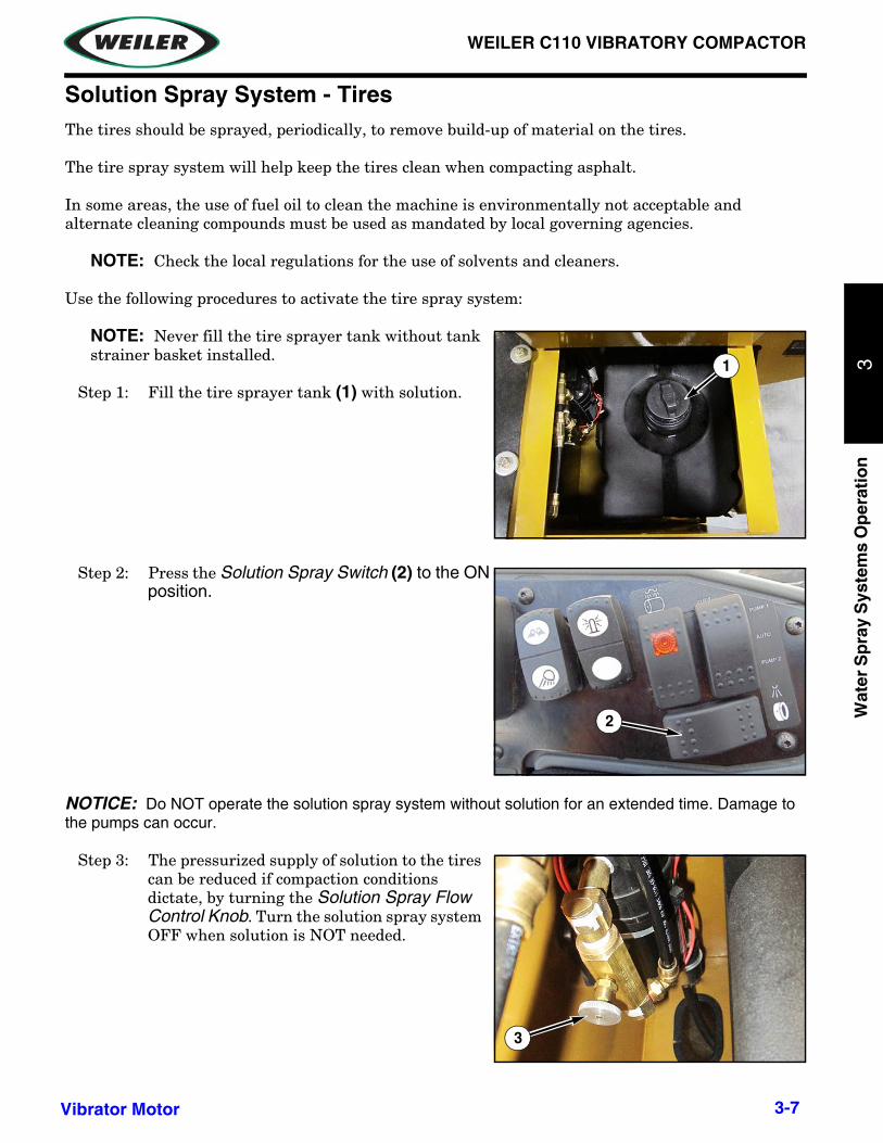
Solution Spray System - TiresThe tires should be sprayed, periodically, to remove build-up of material on the tires.
The tire spray system will help keep the tires clean when compacting asphalt.
In some areas, the use of fuel oil to clean the machine is environmentally not acceptable and alternate cleaning compounds must be used as mandated by local governing agencies.
NOTE: Check the local regulations for the use of solvents and cleaners.
Use the following procedures to activate the tire spray system:
NOTE: Never fill the tire sprayer tank without tank strainer basket installed.
Step 1: Fill the tire sprayer tank (1) with solution.
Step 2: Press the Solution Spray Switch (2) to the ON position.
NOTICE: Do NOT operate the solution spray system without solution for an extended time. Damage to the pumps can occur.
Step 3: The pressurized supply of solution to the tires can be reduced if compaction conditions dictate, by turning the Solution Spray Flow Control Knob. Turn the solution spray system OFF when solution is NOT needed.
1
2
3
3-7Vibrator Motor

1
WEILER C110 VIBRATORY COMPACTOR
Water S
pray S
ystems O
pera-
3
Machine Wash-downAt the end of the day’s operation, the machine should be washed down to remove build-up of material on the drum, drum scraper, and tires. At this time, the 10 hour lubrication points on the lube chart should also be serviced.
In some areas, the use of fuel oil to clean the machine is environmentally not acceptable and alternate cleaning compounds must be used as mandated by local governing agencies.
NOTICE: Regardless of what cleaning solutions are used, it is important that the machine be cleaned and lubricated at the end of each working day to obtain normal life of wear components on the machine.
NOTE: Check the local regulations for the use of solvents and cleaners.
Step 1: Stop the machine on level ground in an area away from the mat and engage the park brake. Shut off the engine. If it is necessary to park the machine on a grade, block the roller and tires securely.
NOTE: Do not spray the fuel oil or solvents on the following components: hydraulic hoses, electrical connections, and electrical cables.
Step 2: Spray the drum, scraper, and tires.
Step 3: Remove all material buildup on the drum and scraper.
3-8 Vibrator Motor

3
WEILER C110 VIBRATORY COMPACTOR
Wat
er S
pra
y S
yste
ms
Op
erat
ion
SPRAY DOWN SYSTEM - ELECTRICAL SCHEMATIC
3-9Spray Down System - Electrical Schematic

WEILER C110 VIBRATORY COMPACTOR
Water S
pray S
ystems O
peratio
n3
WATER SPRAY SCHEMATIC
3-10 Water Spray Schematic

3
WEILER C110 VIBRATORY COMPACTOR
Wat
er S
pra
y S
yste
ms
Op
erat
ion
SOLUTION SPRAY SCHEMATIC
3-11Solution Spray Schematic

This page left intentionally blank.

WEILER C110 VIBRATORY COMPACTOR
Vib
rato
ry U
nit
Mai
nte
nan
ce4
SECTION 4: VIBRATORY UNIT MAINTENANCE
The following information is from the “Caterpillar CB54 and CB64 Vibratory Asphalt Compactors Operation and Maintenance Manual”, part number KEBU7548-01 July 2010.
4-1

1
WEILER C110 VIBRATORY COMPACTOR
Vib
ratory U
nit M
ainten
ance
4
KEBU7548-01July 2010
Operation andMaintenanceManualCB54 and CB64 Vibratory AsphaltCompactorsDJM1-Up (Machine)JLM1-Up (Machine)
4-2SAFETY.CAT.COM

WEILER C110 VIBRATORY COMPACTOR
Vib
rato
ry U
nit
Mai
nte
nan
ce4
68 KEBU7548-01Maintenance Section
Lubricant Viscosities and Re�ll CapacitiesFinal Drive and Eccentric WeightHousingDo not use SAE 50 viscosity grade oil in ICMcontrolled transmissions. Do not use SAE 50viscosity grade oil for the hydraulic drive winch case.
Where recommended for use, Cat TDTO SAE 50or TO-4 SAE 50 is preferred in most applications,particularly continuous operation. If the ambienttemperature is below 15 °C (5 °F), warm up theoil prior to operation. The oil must be maintainedto a temperature above 15 °C (5 °F) duringoperation. If the ambient temperature is below15 °C (5 °F), perform the procedures in theOperation and Maintenance Manual , “Engine andMachine Warm-Up” prior to operation. If the ambienttemperature is below 25 °C ( 13 °F), consult yourCaterpillar dealer for instructions. Failure to warm upthe oil prior to operation will cause damage to themachine.
Do not use API GL-5 or API GL-4 Gear Oils for theVibratory support, the Final Drive Planetary (Drum),or the Eccentric Weight Housing. 4C-6767 SyntheticOil is a premium PAO (Polyalpaole�n) synthetic gearand bearing lubricant with no viscosity improvers.This lubricant has an ISO viscosity grade of 220,and a minimum viscosity index of 152. Commercialoil selected for this application should have a fullsynthetic base stock with no viscosity improvers, anISO viscosity grade of 220, and a minimum viscosityindex of 150.
For low temperatures, do not use API GL-5 or APIGL-4 Gear Oils for the Vibratory support, the FinalDrive Planetary (Drum), or the Eccentric WeightHousing. Select a commercial full synthetic gear andbearing lubricant with no viscosity improvers andwith ISO 68 viscosity grade. This lubricant shouldhave a minimum viscosity index of 145, and have aminimum pour point of 47 °C ( 53 °F).
Table 9
Lubricant Viscosities for Ambient Temperatures
°C °FCompartment or System Oil Type and Classi�cation Oil Viscosities
Min Max Min Max
synthetic ISO 220 -20 50 -4 122Final Drive Planetary (Drum)
Cat Synthetic CompactorOil (4C-6767)
commercial synthetic synthetic ISO 68 -47 21 -53 70
Eccentric Weight HousingCat Synthetic Compactor
Oil (4C-6767)commercial synthetic
synthetic ISO 220 -20 50 -4 122
Special Lubricants
Grease
In order to use a non-Cat grease, the supplier mustcertify that the lubricant is compatible with Catgrease.
Table 10
Ambient Temperature Range
° C ° FApplication Point Typical Loadand Speed Load Factor
Min Max Min Max
NLGIGrade
GreaseType
35 40 31 104 1
High
Vibration80-100%, heavycohesive soil,350 mm (12) lifts
or more.30 50 22 122 2
Ultra 5MolyGrease
MediumVibration 50-80%,granular soil,100mm-305 mm(4-12) lifts.
20 40 4 104 2Advanced3MolyGrease
Lubrication Points
Vibration 30-50%,asphalt mix, Multipurpose
4-3Low 51mm - 100 mm
(2-4) lifts.
30 40 22 104 2 Grease

1
WEILER C110 VIBRATORY COMPACTOR
Vib
ratory U
nit M
ainten
ance
4
72 KEBU7548-01Maintenance SectionLubricant Viscosities and Re�ll Capacities
Standard Factory Fill FluidsTable 12
Standard Factory Fill Fluids(1)
°C °FCompartment or System Oil Viscosities
Min Max Min Max
Final Drive Planetary (Drum) synthetic ISO 220 -20 50 -4 122
Eccentric Weight Housing synthetic ISO 220 -20 50 -4 122(1) The machine is delivered from the factory with the designated �uids.
i03286178
Capacities (Re�ll)SMCS Code: 1000; 6320; 7000; 7560
Table 13
Re�ll CapacitiesApproximate
Compartmentor System Liters US Gallon Imperial
Gallons
Drum Drive(Planetary) 2.4 0.6 0.5
EccentricWeightHousing
11.8 3.1 2.6
EccentricWeightHousing
9.0 2.4 2.0
4-4
WEILER C110 VIBRATORY COMPACTOR
Vib
rato
ry U
nit
Mai
nte
nan
ce4
KEBU7548-01 87Maintenance Section
Drum Drive Planetary Oil - Change
i03288460
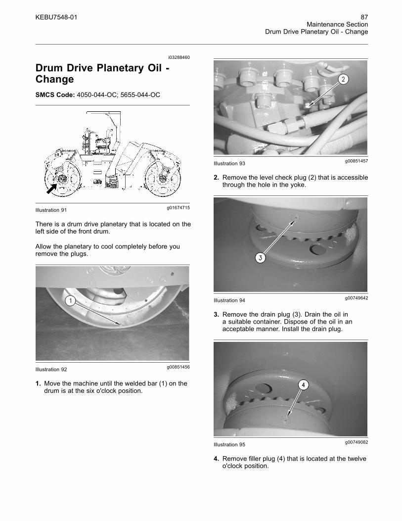
Drum Drive Planetary Oil -ChangeSMCS Code: 4050-044-OC; 5655-044-OC
g01674715Illustration 91
There is a drum drive planetary that is located on theleft side of the front dru .
Allow the planetary to cool completely before youremove the plugs.
g00851456Illustration 92
1. Move the machine until the welded bar (1) on thedrum is at the six o'clock position.
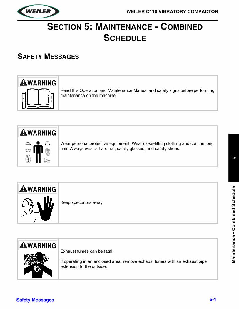
g00851457Illustration 93
2. Remove the level check plug (2) that is accessiblethrough the hole in the yoke.
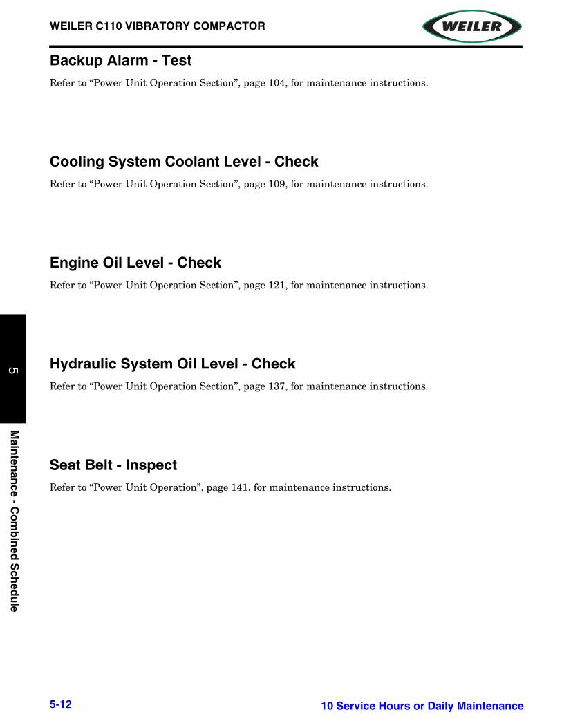
g00749642Illustration 94
3. Remove the drain plug (3). Drain the oil ina suitable container. Dispose of the oil in anacceptable manner. Install the drain plug.
g00749082Illustration 95
4. Remove �ller plug (4) that is located at the twelveo'clock position.
4-5

1
WEILER C110 VIBRATORY COMPACTOR
Vib
ratory U
nit M
ainten
ance
4
88 KEBU7548-01Maintenance SectionDrum Drive Planetary Oil Level - Check
5. Refer to the Operation and Maintenance Manual,“Lubricant Viscosities and Capacities (Re�ll)”.Fill the drum drive planetary until the oil is at thebottom of the level check plug opening.
6. Clean the level check plug (2) and then install thelevel check plug.
7. Clean the �ller plug (4) and then install the �llerplug.
8. Repeat the procedure for the opposite planetary.
i01696643
Drum Drive Planetary Oil Level- CheckSMCS Code: 4050-535-FLV; 5655-535-FLV
There is a drum drive planetary that is located on theleft side of the front drum and on the right side of therear drum.
g00946345Illustration 96
1. Remove level check plug (1).
2. Check the level of the oil in the planetary. Maintainthe level of the oil at the bottom of the level checkplug opening.
g00946370
3. If the oil level is low, remove �ller plug (2).
4. Refer to the Operation and Maintenance Manual,“Lubricant Viscosities and Capacities (Re�ll)”. Fillthe planetary until the oil is at the bottom of thelevel check plug opening.
5. Clean level check plug (2) and then install thelevel check plug.
6. Clean �ller plug (3) and then install the �ller plug.
7. Repeat the procedure for the opposite drum driveplanetary.
i01940657
Drum Drive Planetary OilSample - ObtainSMCS Code: 4050-008-DM; 5655-008-DM
There is a drum drive planetary that is located on theleft side of the front drum and on the right side of therear drum.
g01009809Illustration 98
1. Remove level check plug (1).
2. Obtain an oil sample from the hole for the levelcheck plug.
3. Use a sampling gun to obtain the oil sample.
Note: Refer to Special Publication, SEBU6250 forfurther information on obtaining oil samples.
4. Clean the level check plug and then install thelevel check plug.
5. Repeat the procedure for the opposite drum driveplanetary.
4-6Illustration 97

WEILER C110 VIBRATORY COMPACTOR
Vib
rato
ry U
nit
Mai
nte
nan
ce4
KEBU7548-01 89Maintenance Section
i02583458
Eccentric Weight Housing Oil- ChangeSMCS Code: 6606-044-OC
Change the Oil1. Take an oil sample from each eccentric weighthousing. There is an eccentric weight housing inthe left front drum. There is an eccentric weighthousing in the right rear drum. No �ushing isnecessary, if the oil sample cleanliness ratingis equal or lower than ISO 23/21. The �ushingprocedure should be performed if an oil samplecleanliness rating is higher than ISO 23/21.
g00946406Illustration 101
2. Rotate the drum so that �ll/drain plug (1) is at thebottom. Place a suitable container under �ll/drainplug (1). Remove �ll/drain plug (1). Drain thehousing completely.
g00946405Illustration 102
3. Rotate the drum until the welded item (2) is at thebottom of the drum. The sight gauge (3) should beat the bottom of the housing. This will move the�ll/drain plug (1) to the upper position.
4. Fill the housing with oil. Refer to the Operation andMaintenance Manual, “Lubrication Viscosities” andOperation and Maintenance Manual, “Capacities(Re�ll)”. Maintain the level of the oil to the middleof the sight gauge.
5. Clean �ll/drain plug (1) and install �ll/drain plug (1).
4-7

1
WEILER C110 VIBRATORY COMPACTOR
Vib
ratory U
nit M
ainten
ance
4
90 KEBU7548-01Maintenance SectionEccentric Weight Housing Oil - Change
Flush the Housing
Crush Hazard! Machine movement while makingadjustments can cause injury or death.
Shut off engine and remove key before making ad-justments.
Refer to the Operation and Maintenance Manualfor the proper adjustment procedures.
NOTICECare must be taken to ensure that �uids are containedduring performance of inspection, maintenance, test-ing, adjusting and repair of the machine. Be preparedto collect the �uid with suitable containers beforeopening any compartment or disassembling any com-ponent containing �uids.
Refer to Special Publication, NENG2500, “CaterpillarTools and Shop Products Guide”, for tools and sup-plies suitable to collect and contain �uids in Caterpillarmachines.
Dispose of all �uids according to local regulations andmandates.
The �ushing procedure should be used after theeccentric weight housing has been opened up forrepair.
There are two eccentric weight housings. There isone eccentric weight housing in the front drum. Thereis one eccentric weight housing in the rear drum.
1. Drain the oil from the eccentric weight housing.
2. Pump 76 L (20 US gal) of a suitable hydraulic oilinto a 208 L (55 US gal) drum.
g00950298Illustration 103(4) 8C-6875 Connector(5) 8B-5774 Reducer Bushing(6) 9U-6989 Head(7) 9U-6983 Filter Element(8) 6V-3965 Nipple Assembly(9) 8T-4834 Swivel Ori�ce Tee(10) 127-8781 Transfer Cart Group(11) Use 2.4 m (8 ft) of hose with a diameter of 25 mm (1 inch).(12) 3B-6498 Elbow(13) 3L-7024 Street Elbow(14) 127-0593 Connector(15) 3B-7728 Elbow(16) 3B-7265 Pipe Nipple(17) Use 940 mm (37 inch) 25 mm (1 inch)of pipe with a 45° angle
cut at one end.
3. Use the 127-8781 Transfer Cart Group (10) inorder to �ush the oil in the 208 L (55 US gal) drum.Filter the oil for 30 minutes. The particle count ofthe clean oil must be a maximum of ISO 18/13.
g00728721Illustration 104
Typical example
4. Raise the machine. The drums must not be incontact with the ground or the �oor. Support themachine on stands.
4-8

WEILER C110 VIBRATORY COMPACTOR
Vib
rato
ry U
nit
Mai
nte
nan
ce4
KEBU7548-01 91Maintenance Section
Eccentric Weight Housing Oil - Change
g00946405Illustration 105
5. Start the engine. Release the parking brake androtate the drum until sight gauge (3) is at the topof the housing. Remove sight gauge (3). Installthe �tting assembly that is appropriate for yourmachine.
Note: The following steps are for machines that areequipped with a STOR oil �ller plug.
6. Assemble the 126-7187 Adapter (11) intothe male end of the 5R-3796 Quick CouplingAssembly (10). Install the adapter into the holefor the sight glass. Assemble the 8T-0198 SealConnector (8) onto the female end of the 5R-3796Quick Coupling Assembly (9). Attach the femaleend of quick coupler (9) to the suction hose of thetransfer cart (7).
7. Rotate the drum until indicator (2) is at the bottomof the drum. The male end of the quick disconnectplug will be located at the six o'clock position.
8. Open the �ller plug to the ten o'clock position.
9. Connect the transfer cart. Fill the housing with22 L (6 US gal) gallons of clean oil. Disconnectthe transfer cart.
10. Tighten the �ller plug at the ten o'clock position.
11.Run the �rst �ush cycle.
a. Adjust the amplitude setting wheel to the lowposition on both drums.
b. Start the engine. Release the brake.
c. Set the travel speed control to low speed.In order to rotate the drum, move the propelcontrol lever.
d. Use the switch for the vibratory mode control inorder to select the desired drum.
e. Select the Manual position on the vibratorycontrol switch.
f. Turn on the vibratory system. Run the vibratorysystem for 5 seconds. Turn off the vibratorysystem. Repeat the cycle for three minutes.
Note: For each cycle, do not run the vibratory systemmore than 5 seconds.
g. Stop the drum. Rotate the drum until indicator(2) is at the bottom of the drum. The male endof the quick disconnect will be located at thesix o'clock position.
h. Apply the parking brake. Shut off the engine.Remove the key.
12.Open the �ller plug at the ten o'clock position.
13. Install the transfer cart. Pump the oil out of thehousings. Disconnect the transfer cart. Cycle theoil through the �lter for 30 minutes. Cycle the oiluntil the oil is cleaned to a rating of ISO 18/13 orbetter.
14. Install the transfer cart to the housings. Pump theoil into the housings. For the second cycle, repeat7 through 13. After the second cycle, take an oilsample before �ltering the oil. No further �ushing isnecessary, if the oil sample rating is equal or lowerthan ISO 19/16. Another �ushing is necessary, ifthe oil sample rating is higher than ISO 19/16.
15.When the �ushing is complete, rotate the drumuntil indicator (2) is at the bottom of the drum.Place a suitable container under the �ttingassembly. In order to drain all the oil, raise thevibratory motor side of the drum higher. Removethe �tting assembly. Drain as much of the oil aspossible.
16.Clean the sight gauge. Install sight gauge (3).
g00946406Illustration 106
17.Remove �ller plug (1) at the ten o'clock position.
4-9

1
WEILER C110 VIBRATORY COMPACTOR
Vib
ratory U
nit M
ainten
ance
4
92 KEBU7548-01Maintenance SectionEccentric Weight Housing Oil Level - Check
18. Fill the housing with oil. Refer to the Operation andMaintenance Manual, “Lubrication Viscosities” andOperation and Maintenance Manual, “Capacities(Re�ll)”. Maintain the level of the oil to the middleof the sight gauge.
19.Clean the �ller plug. Install �ller plug (1).
Note: The new oil must have a particle count of ISO19/16 or better than ISO 19/16.
i03434143
Eccentric Weight Housing OilLevel - CheckSMCS Code: 6606-535-FLV
There is an eccentric weight housing in the left frontdrum. There is an eccentric weight housing in theright rear drum.
g01086108Illustration 107
1. Rotate the drum until indicator bar (1) is at thebottom of the drum. The sight gauge (3) will be atthe bottom of the housing.
2. Observe the level of oil in the sight gauge. The oillevel should be visible in the center of the sightgauge.
g01086110
3. If the lubricant level is low, remove �ll/drain plug(2) at the ten o'clock position.
4. Add the correct amount of oil. Refer to theMaintenance Manual, “Lubrication Viscosities”and Maintenance Manual, “Capacities (Re�ll)”.Maintain the level of the oil to the middle of thesight gauge.
5. Clean �ll/drain plug (2). Install �ll/drain plug (2).
Note: Do not over�ll the eccentric weight housing. Ifthe eccentric weight housing is over�lled the excessoil must be drained out. An eccentric weight housingthat has been over�lled can lead to excessive heatgeneration and loss of vibratory system performance.
i01857371
Vibratory Frequency - CheckSMCS Code: 6606-535
Check the speed of the vibratory system. Refer toTesting and Adjusting, “Vibratory Frequency - Testand Adjust” for information on checking the VPM.
4-10Illustration 108

WEILER C110 VIBRATORY COMPACTOR
Vib
rato
ry U
nit
Mai
nte
nan
ce4
KEBU7548-01 111Maintenance Section
Oil Filter - Inspecti03762488
Ring Bearings - LubricateSMCS Code: 6605-086-BD
Park the machine before accessing the grease�ttings and applying the grease.
There are two separate ring bearings that needlubrication. The ring bearing for the front drum islocated on the right side of the front drum. The ringbearing for the rear drum is located on the left side ofthe rear drum.
g01387085Illustration 148Typical Example
Lubricate both grease �ttings on the ring bearings.
In order to provide more even distribution of the newgrease, perform the following steps for each bearing:
1. Apply about 15 grams of lubricant to each �tting.
2. Rotate the bearing 30 to 45 degrees and apply thespeci�ed amount of lubricant.
3. Repeat step 2 until the bearing has been rotatedat least 180 degrees.
A total of about 150 grams of lubricant should beapplied to each bearing during each re lubrication.
4-11

This page intentionally left blank.
WEILER C110 VIBRATORY COMPACTOR
Mai
nte
nan
ce -
Co
mb
ined
Sch
edu
le5
SECTION 5: MAINTENANCE - COMBINED SCHEDULE
SAFETY MESSAGES
Read this Operation and Maintenance Manual and safety signs before performing maintenance on the machine.
Wear personal protective equipment. Wear close-fitting clothing and confine long hair. Always wear a hard hat, safety glasses, and safety shoes.
Keep spectators away.
Exhaust fumes can be fatal.
If operating in an enclosed area, remove exhaust fumes with an exhaust pipe extension to the outside.
5-1Safety Messages

1
WEILER C110 VIBRATORY COMPACTOR
Main
tenan
ce - Co
mb
ined
Sch
edu
le5
Raised machine or attachment can fall and crush you.
Never work under a raised machine or attachment unless securely supported with secure blocking.
Hot fluid under pressure can scald.
Allow engine to cool before opening radiator cap.
Fuel and fumes can explode and burn.
Shut off engine before refueling. No flame. No smoking.
Battery fumes are flammable and can explode. Keep all burning materials away from battery. Battery explosion can blind. Acid can blind and burn. Tools and cable clamps can make sparks.
Do not smoke. Shield eyes and face.
5-2 Safety Messages

WEILER C110 VIBRATORY COMPACTOR
Mai
nte
nan
ce -
Co
mb
ined
Sch
edu
le5
Serious injury or death from crushing could occur in this area when the front steering drum turns.
Stay out of area between frame and front steering drum.
Pressurized fluid can penetrate body tissue and result in serious injury or death. Leaks can be invisible. Keep away from any suspected leak. Relieve pressure in the hydraulic system before searching for leaks, disconnecting hoses, or performing any other work on the system. If you must pressurize the system to find a suspected leak, use an object such as a piece of wood or cardboard rather than your hands. When loosening a fitting where some residual pressure may exist, slowly loosen the fitting until oil begins to leak. Wait for leaking to stop before disconnecting the fitting. Fluid injected under the skin must be removed immediately by a surgeon familiar with this type of injury.
Keep hands, feet, and clothing away from power-driven parts. Keep shields in place and properly secured.
Use Shutdown Procedure before servicing, cleaning, repairing or transporting machine. Refer to Shutdown Procedure for instructions.
5-3Safety Messages

1
WEILER C110 VIBRATORY COMPACTOR
Main
tenan
ce - Co
mb
ined
Sch
edu
le5
Pinch Point. Loss of fingers or hands can result if steering drum pivots.
Keep hands out of area.
Make no modifications to this equipment unless specifically recommended by Weiler.
Be sure that all safety devices, including shields, are installed and functioning properly before returning the machine to service.
Failure to follow any of the preceding safety instructions or those that follow within this manual, could result in serious injury or death. This machine is to be used only for those purposes for which it was intended as explained in the Operation section of this manual.
5-4 Safety Messages

WEILER C110 VIBRATORY COMPACTOR
Mai
nte
nan
ce -
Co
mb
ined
Sch
edu
le5
GENERAL INFORMATION
Welding PrecautionsNOTICE: Refer to “Power Unit Operation Section” page 100, for instructions on Welding on Machines and Engines with Electronic Controls.
LUBRICATION CHART
NOTICE: Refer to “Power Unit Operation Section” page 93 for instructions on Lubricant Viscosities and Refill Capacities.
5-5General Information

1
WEILER C110 VIBRATORY COMPACTOR
Main
tenan
ce - Co
mb
ined
Sch
edu
le5
MAINTENANCE INTERVALS
LUBRICATION / SERVICE HOURSInterval Identification Remarks
Every 10 Hours or Daily
Drum Roller Bearing Grease. 10 shots each grease point.Backup Alarm TestCooling System Coolant Level CheckEngine Oil Level CheckHydraulic System Oil Level CheckSeat Belt Inspect
Every 50 Hours or Weekly
Water Spray Tank Strainer CleanFuel Tank Water and Sediment DrainSteering Cylinder Ends LubricateRing Bearings Lubricate
Every 100 Hours
Overall Machine Check for DamageSafety Signs Check for DamageTires Check PressureEmergency Stop Knob Test
Initial 250 Hours
Axle Oil (Rear) ChangeFinal Drive Planetary (Axle) Oil ChangeDrum Drive Planetary Oil Change
Every 250 Hours Cooling System Coolant Sample (Level 1) Obtain
Every 250 Hours or 3
Months
Axle Oil Level (Rear) CheckBelts Inspect/Adjust/ReplaceEngine Oil Sample ObtainFinal Drive Planetary (Axle) Oil Level CheckDrum Drive Planetary Oil Level CheckEccentric Weight Housing Oil Level Check
Every 500 Hours
Fuel Tank Strainer CheckHood Latch Adjust
Every 500 Hours or 6
Months
Axle Oil Sample ObtainEngine Oil and Filter ChangeFuel System Primary Filter (Water Separator)
Replace
Fuel System Secondary Filter ReplaceHydraulic System Oil Sample ObtainParking Brake CheckDrum Drive Planetary Oil Sample Obtain
Every 1000 Hours
Solution Spray Pump Filter Replace
Drum Drive Planetary Oil Change
5-6 Maintenance Intervals

WEILER C110 VIBRATORY COMPACTOR
Mai
nte
nan
ce -
Co
mb
ined
Sch
edu
le5
Every 1000 Hours or 1
Year
Drum Vibration Motor Check/AdjustAxle Oil (Rear) ChangeCooling System Pressure Cap Clean/ReplaceFinal Drive Planetary (Axle) Oil ChangeFinal Drive Planetary (Axle) Oil Sample ObtainHydraulic System Oil Filter ReplaceHydraulic Tank Breather ReplaceRollover Protective Structure (ROPS) InspectVibratory Frequency Check
Every 2000 Hours Fuel Tank Cap Filter Replace
Every 2000 Hours or 1
YearFumes Disposal Filter Element Replace
Every Year Cooling System Coolant Sample (Level 2) ObtainEvery 3000
Hours Steering Column Spline (HMU Steering) Lubricate
Every 3000 Hours or
18 MonthsHydraulic System Oil Change
Every 3000 or 2 Years
Cooling System Water Temperature Regulator
Replace
Every 3000 Service
Hours or 3 Years
Eccentric Weight Housing Oil Change
Every 3 Years Seat Belt Replace
Every 6000 Hours or 3
YearsCooling System Coolant Extender (ELC) Add
Every 12,000
Hours or 6 Years
Cooling System Coolant (ELC) Change
5-7Maintenance Intervals

1
WEILER C110 VIBRATORY COMPACTOR
Main
tenan
ce - Co
mb
ined
Sch
edu
le5
When Required
Water Spray Nozzles CleanSolution Spray Nozzles CleanBattery Clean/CheckBattery RecycleBattery or Battery Cable Inspect/ReplaceCab Air Filter Clean/ReplaceEngine Air Filter Primary Element Clean/ReplaceEngine Air Filter Secondary Element ReplaceFilm (Product Identification) CleanFuel System PrimeFuses ReplaceOil Filter InspectRadiator Core CleanTire Spacing ChangeWheel Nuts TightenWindow Washer Reservoir FillWindow Wiper Inspect/ReplaceWindows Clean
5-8 Maintenance Intervals

WEILER C110 VIBRATORY COMPACTOR
Mai
nte
nan
ce -
Co
mb
ined
Sch
edu
le5
MAINTENANCE INTERVAL SCHEDULE
Ensure that all safety information, warnings and instructions are read and understood before any operation or any maintenance procedures are performed.
The user is responsible for the performance of maintenance, including all adjustments, the use of proper lubricants, fluids, filters, and the replacement of components due to normal wear and aging. Failure to adhere to proper maintenance intervals and procedures may result in diminished performance of the product and/or accelerated wear of components.
Use fuel consumption, service hours, or calendar time, WHICH EVER OCCURS FIRST, in order to determine the maintenance intervals. Products that operate in severe operating conditions may require more frequent maintenance.
NOTE: Before each consecutive interval is performed, all maintenance from the previous interval must be performed.
5-9Maintenance Interval Schedule

1
WEILER C110 VIBRATORY COMPACTOR
Main
tenan
ce - Co
mb
ined
Sch
edu
le5
MACHINE - GREASE
As a general rule, grease machine after it is shut down for the day. This protects the metal under the seals from corrosion caused by condensation as the temperature drops.
Ensure all fittings and grease applicator nozzle are clean before applying grease. If any grease fittings are missing, replace them immediately.
Recommended FluidsRefer to "Specifications" page 1-3 of Section 1: General Information, for fluid and lubricant
requirements.
5-10 Machine - Grease

WEILER C110 VIBRATORY COMPACTOR
Mai
nte
nan
ce -
Co
mb
ined
Sch
edu
le5
10 SERVICE HOURS OR DAILY MAINTENANCE
Drum Roller BearingTen shots each, two fittings (1), on right side of machine.
1
1
5-1110 Service Hours or Daily Maintenance
1
WEILER C110 VIBRATORY COMPACTOR
Main
tenan
ce - Co
mb
ined
Sch
edu
le5
Backup Alarm - TestRefer to “Power Unit Operation Section”, page 104, for maintenance instructions.
Cooling System Coolant Level - CheckRefer to “Power Unit Operation Section”, page 109, for maintenance instructions.
Engine Oil Level - CheckRefer to “Power Unit Operation Section”, page 121, for maintenance instructions.
Hydraulic System Oil Level - CheckRefer to “Power Unit Operation Section”, page 137, for maintenance instructions.
Seat Belt - InspectRefer to “Power Unit Operation”, page 141, for maintenance instructions.
5-12 10 Service Hours or Daily Maintenance

WEILER C110 VIBRATORY COMPACTOR
Mai
nte
nan
ce -
Co
mb
ined
Sch
edu
le5
50 HOUR OR WEEKLY MAINTENANCE
Water Spray Tank StrainerRemove water tank fill cap and clean the strainer basket (1).
Fuel Tank Water and Sediment - DrainRefer to “Power Unit Operation Section”, page 132, for maintenance instructions.
Steering Cylinder Ends - LubricateRefer to “Power Unit Operation Section”, page 144, for maintenance instructions.
Ring Bearings - LubricateRefer to “Vibratory Unit Maintenance Section”, page 111, for maintenance instructions.
1
5-1350 Hour or Weekly Maintenance

1
WEILER C110 VIBRATORY COMPACTOR
Main
tenan
ce - Co
mb
ined
Sch
edu
le5
100 HOUR MAINTENANCE
Overall Machine - CheckShields and Guards - Check that all shields and guards are installed and are fastened securely to machine. Replace and repair any shields or guards that are damaged or have missing parts.
Hardware - Check machine for loose, worn, or missing parts and hardware. Tighten any loose parts and replace any worn or missing parts. Refer to the Parts Manual for replacement parts.
Frame - Check machine frame and contact Weiler dealer immediately if you notice any bending or cracking.
ROPS - Check for cracking of ROPS and torque of ROPS mounting bolts. Contact Weiler dealer immediately if you notice cracking. Re-tighten bolts if loose. Refer to “Power Unit Operation Section”, page 141, for maintenance instructions.
Fire Prevention - Keep engine compartment, battery, hydraulic lines, fuel tank and operator’s station clean of accumulated trash, grease, and debris.
Electrical Harness - Check that electrical harness and all wires are properly supported and not rubbing on any sharp corners. Support any loose wires hanging under machine frame.
Engine Belts - Inspect for worn, cracked, or frayed belts. Replace if worn or damaged.
5-14 100 Hour Maintenance
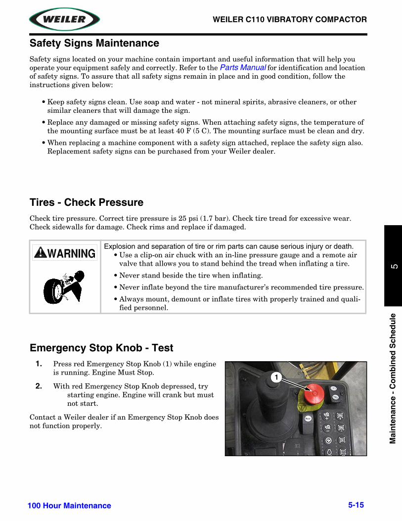
WEILER C110 VIBRATORY COMPACTOR
Mai
nte
nan
ce -
Co
mb
ined
Sch
edu
le5
Safety Signs MaintenanceSafety signs located on your machine contain important and useful information that will help you operate your equipment safely and correctly. Refer to the Parts Manual for identification and location of safety signs. To assure that all safety signs remain in place and in good condition, follow the instructions given below:
• Keep safety signs clean. Use soap and water - not mineral spirits, abrasive cleaners, or othersimilar cleaners that will damage the sign.
• Replace any damaged or missing safety signs. When attaching safety signs, the temperature ofthe mounting surface must be at least 40 F (5 C). The mounting surface must be clean and dry.
• When replacing a machine component with a safety sign attached, replace the safety sign also.Replacement safety signs can be purchased from your Weiler dealer.
Tires - Check PressureCheck tire pressure. Correct tire pressure is 25 psi (1.7 bar). Check tire tread for excessive wear. Check sidewalls for damage. Check rims and replace if damaged.
Emergency Stop Knob - Test1. Press red Emergency Stop Knob (1) while engine
is running. Engine Must Stop.
2. With red Emergency Stop Knob depressed, trystarting engine. Engine will crank but must not start.
Contact a Weiler dealer if an Emergency Stop Knob does not function properly.
Explosion and separation of tire or rim parts can cause serious injury or death.• Use a clip-on air chuck with an in-line pressure gauge and a remote air
valve that allows you to stand behind the tread when inflating a tire.
• Never stand beside the tire when inflating.
• Never inflate beyond the tire manufacturer’s recommended tire pressure.
• Always mount, demount or inflate tires with properly trained and quali-fied personnel.
1
5-15100 Hour Maintenance

1
WEILER C110 VIBRATORY COMPACTOR
Main
tenan
ce - Co
mb
ined
Sch
edu
le5
INITIAL 250 SERVICE HOURS MAINTENANCE
Axle Oil (Rear) - ChangeRefer to “Power Unit Operation Section”, page 103, for maintenance instructions.
Final Drive Planetary (Axle) Oil - ChangeRefer to “Power Unit Operation Section”, page 125, for maintenance instructions.
Drum Drive Planetary Oil - ChangeRefer to “Vibratory Unit Maintenance Section”, page 87, for maintenance instructions.
EVERY 250 SERVICE HOURS MAINTENANCE
Cooling System Coolant Sample (Level 1) - ObtainRefer to “Power Unit Operation Section”, page 109, for maintenance instructions.
5-16 Initial 250 Service Hours Maintenance

WEILER C110 VIBRATORY COMPACTOR
Mai
nte
nan
ce -
Co
mb
ined
Sch
edu
le5
EVERY 250 SERVICE HOURS OR 3 MONTHS MAINTENANCE
Axle Oil Level (Rear) - CheckRefer to “Power Unit Operation Section”, page 104, for maintenance instructions.
Belts - Inspect/Adjust/ReplaceRefer to “Power Unit Operation Section”, page 105, for maintenance instructions.
Engine Oil Sample - ObtainRefer to “Power Unit Operation Section”, page 122, for maintenance instructions.
Final Drive Planetary (Axle) Oil Level - CheckRefer to “Power Unit Operation Section”, page 125, for maintenance instructions.
Drum Drive Planetary Oil Level - CheckRefer to “Vibratory Unit Maintenance Section”, page 88, for maintenance instructions.
Eccentric Weight Housing Oil Level - CheckRefer to “Vibratory Unit Maintenance Section”, page 92, for maintenance instructions.
5-17Every 250 Service Hours or 3 Months Mainte-

1
WEILER C110 VIBRATORY COMPACTOR
Main
tenan
ce - Co
mb
ined
Sch
edu
le5
EVERY 500 SERVICE HOURS MAINTENANCE
Fuel Tank Strainer - CleanRefer to “Power Unit Operation Section”, page 132, for maintenance instructions.
Hood Latch - AdjustRefer to “Power Unit Operation Section”, page 135, for maintenance instructions.
5-18 Every 500 Service Hours Maintenance

WEILER C110 VIBRATORY COMPACTOR
Mai
nte
nan
ce -
Co
mb
ined
Sch
edu
le5
EVERY 500 SERVICE HOURS OR 6 MONTHS MAINTENANCE
Axle Oil Sample - ObtainRefer to “Power Unit Operation Section”, page 104, for maintenance instructions.
Engine Oil and Filter - ChangeRefer to “Power Unit Operation Section”, page 123, for maintenance instructions.
Fuel System Primary Filter (Water Separator) - ReplaceRefer to “Power Unit Operation Section”, page 128, for maintenance instructions.
Fuel System Secondary Filter - ReplaceRefer to “Power Unit Operation Section”, page 130, for maintenance instructions.
Hydraulic System Oil Sample - ObtainRefer to “Power Unit Operation Section”, page 138, for maintenance instructions.
Parking Brake - CheckRefer to “Power Unit Operation Section”, page 140, for maintenance instructions.
Drum Drive Planetary Oil Sample - ObtainRefer to “Vibratory Unit Maintenance Section”, page 88, for maintenance instructions.
5-19Every 500 Service Hours or 6 Months Mainte-

1
WEILER C110 VIBRATORY COMPACTOR
Main
tenan
ce - Co
mb
ined
Sch
edu
le5
EVERY 1000 SERVICE HOURS MAINTENANCE
Solution Spray Pump Filter - Replace
Step 1: Place a container under the filter (1) before removing filter.
Step 2: Remove filter.
NOTE: Do not allow dirt to enter system. Throughly clean area around filter before disconnecting.
Step 3: Install new filter.
Step 4: Turn on sprayer system and check for leaks.
Drum Drive Planetary Oil - ChangeRefer to “Vibratory Unit Maintenance Section”, page 87, for maintenance instructions.
Fluid leaked or spilled onto hot surfaces or electrical components can cause a fire. To help prevent possible injury, shut off engine when changing filter. Clean up spills immediately.
1
5-20 Every 1000 Service Hours Maintenance

WEILER C110 VIBRATORY COMPACTOR
Mai
nte
nan
ce -
Co
mb
ined
Sch
edu
le5
1000 HOURS OR 1 YEAR MAINTENANCE
Drum Vibration Motor - CheckNOTE: The desired setting for the drum vibration motor (1) is 2510 – 2530 RPM.
Step 1: Use a photo tachometer to measure the motor’s RPM.
Drum Vibration Motor - AdjustNOTE: The required setting for the drum vibration motor is 2510 – 2530 RPM.
Step 1: Loosen top jam lock (1).
Step 2: Adjust top set screw (2).
NOTE: Turning the top set screw clockwise will decrease RPM. Turning the top set screw counter-clockwise will increase RPM.
NOTE: The bottom set screw may need to be turned counter-clockwise before top set screw can be turned clockwise.
Step 3: Tighten top jam lock (1).
Step 4: Loosen bottom jam lock (3).
Step 5: Adjust bottom set screw (4).
NOTE: Turning the bottom set screw clockwise will increase RPM. Turning the bottom set screw counter-clockwise will decrease RPM.
Step 6: Tighten bottom jam lock.
Step 7: Use a photo tachometer to measure the motor’s RPM. Repeat procedure until desired RPM is reached.
NOTE: Both top and bottom adjustment set screws need to be adjusted so both screws are tight against the cam plate.
1
12
34
5-211000 Hours or 1 Year Maintenance

1
WEILER C110 VIBRATORY COMPACTOR
Main
tenan
ce - Co
mb
ined
Sch
edu
le5
Axle Oil (Rear) - ChangeRefer to “Power Unit Operation Section”, page 103, for maintenance instructions.
Cooling System Pressure Cap - Clean/ReplaceRefer to “Power Unit Operation Section”, page 111, for maintenance instructions.
Final Drive Planetary (Axle) Oil - ChangeRefer to “Power Unit Operation Section”, page 125, for maintenance instructions.
Final Drive Planetary (Axle) Oil Sample - ObtainRefer to “Power Unit Operation Section”, page 126, for maintenance instructions.
Hydraulic System Oil Filter - ReplaceRefer to “Power Unit Operation Section”, page 136, for maintenance instructions.
5-22 1000 Hours or 1 Year Maintenance

WEILER C110 VIBRATORY COMPACTOR
Mai
nte
nan
ce -
Co
mb
ined
Sch
edu
le5
Hydraulic Tank Breather - ReplaceRefer to “Power Unit Operation Section”, page 138, for maintenance instructions.
Rollover Protective Structure (ROPS) - InspectRefer to “Power Unit Operation Section”, page 141, for maintenance instructions.
Vibratory Frequency - CheckRefer to “Vibratory Unit Maintenance Section”, page 92, for maintenance instructions.
5-231000 Hours or 1 Year Maintenance

1
WEILER C110 VIBRATORY COMPACTOR
Main
tenan
ce - Co
mb
ined
Sch
edu
le5
EVERY 2000 SERVICE HOURS MAINTENANCE
Fuel Tank Cap Filter - ReplaceRefer to “Power Unit Operation Section”, page 131, for maintenance instructions.
EVERY 2000 SERVICE HOURS OR 1 YEAR MAINTENANCE
Fumes Disposal Filter Element - ReplaceRefer to “Power Unit Operation Section”, page 132, for maintenance instructions.
EVERY YEAR MAINTENANCE
Cooling System Coolant Sample (Level 2) - ObtainRefer to “Power Unit Operation Section”, page 111, for maintenance instructions.
EVERY 3000 SERVICE HOURS MAINTENANCE
Steering Column Spline (HMU Steering) - LubricateRefer to “Power Unit Operation Section”, page 142, for maintenance instructions.
5-24 Every 2000 Service Hours Maintenance

WEILER C110 VIBRATORY COMPACTOR
Mai
nte
nan
ce -
Co
mb
ined
Sch
edu
le5
EVERY 3000 SERVICE HOURS OR 18 MONTHS MAINTENANCE
Hydraulic System Oil - ChangeRefer to “Power Unit Operation Section”, page 135, for maintenance instructions.
EVERY 3000 SERVICE HOURS OR 2 YEARS MAINTENANCE
Cooling System Water Temperature Regulator - ReplaceRefer to “Power Unit Operation Section”, page 112, for maintenance instructions.
EVERY 3000 SERVICE HOURS OR 3 YEARS MAINTENANCE
Eccentric Weight Housing Oil - ChangeRefer to “Vibratory Unit Maintenance Section”, page 89, for maintenance instructions.
5-25Every 3000 Service Hours or 18 Months

1
WEILER C110 VIBRATORY COMPACTOR
Main
tenan
ce - Co
mb
ined
Sch
edu
le5
EVERY 6000 SERVICE HOURS OR 3 YEARS MAINTENANCE
Cooling System Coolant Extender (ELC) - AddRefer to “Power Unit Operation Section”, page 108, for maintenance instructions.
EVERY 12000 SERVICE HOURS OR 6 YEARS
Cooling System Coolant (ELC) - ChangeRefer to “Power Unit Operation Section”, page 106, for maintenance instructions.
5-26 Every 6000 Service Hours or 3 Years Mainte-
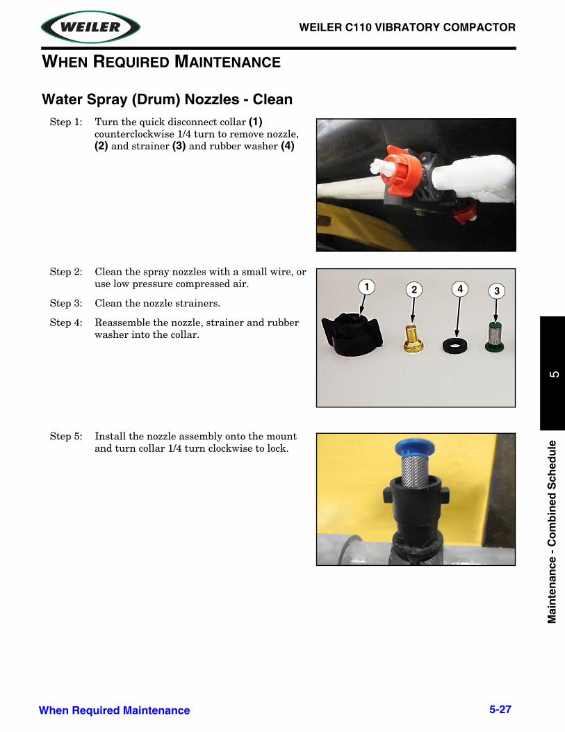
WEILER C110 VIBRATORY COMPACTOR
Mai
nte
nan
ce -
Co
mb
ined
Sch
edu
le5
WHEN REQUIRED MAINTENANCE
Water Spray (Drum) Nozzles - CleanStep 1: Turn the quick disconnect collar (1)
counterclockwise 1/4 turn to remove nozzle, (2) and strainer (3) and rubber washer (4)
Step 2: Clean the spray nozzles with a small wire, or use low pressure compressed air.
Step 3: Clean the nozzle strainers.
Step 4: Reassemble the nozzle, strainer and rubber washer into the collar.
Step 5: Install the nozzle assembly onto the mount and turn collar 1/4 turn clockwise to lock.
1
2 341
5-27When Required Maintenance

1
WEILER C110 VIBRATORY COMPACTOR
Main
tenan
ce - Co
mb
ined
Sch
edu
le5
Solution Spray (Tires) Nozzles - Clean
Step 1: Place a container under nozzles (1) before removing nozzles.
Step 2: Remove nozzle assemblies (2).
Step 3: Turn body (3) counterclockwise to remove nozzle (4) and strainer (5).
Step 4: Clean nozzles using low pressure compressed air.
NOTICE: Do NOT use wire to clean nozzles.
Step 5: Clean nozzle strainers (5).
Step 6: Reassemble the body, strainer, and nozzle into the cap (6).
Step 7: Install the nozzle assembly onto the plate and turn clockwise to tighten.
Fluid leaked or spilled onto hot surfaces or electrical components can cause a fire. To help prevent possible injury, shut off engine when changing filter. Clean up spills immediately.
1
2
3 54
6
5-28 When Required Maintenance

WEILER C110 VIBRATORY COMPACTOR
Mai
nte
nan
ce -
Co
mb
ined
Sch
edu
le5
Battery - Clean/CheckRefer to “Power Unit Operation Section”, page 104, for maintenance instructions.
Battery - RecycleRefer to “Power Unit Operation Section”, page 105, for maintenance instructions.
Battery or Battery Cable - Inspect/ReplaceRefer to “Power Unit Operation Section”, page 105, for maintenance instructions.
Cab Air Filter - Clean/ReplaceRefer to “Power Unit Operation Section”, page 106, for maintenance instructions.
Engine Air Filter Primary Element - Clean/ReplaceRefer to “Power Unit Operation Section”, page 119, for maintenance instructions.
Engine Air Filter Secondary Element - ReplaceRefer to “Power Unit Operation Section”, page 121, for maintenance instructions.
5-29When Required Maintenance

1
WEILER C110 VIBRATORY COMPACTOR
Main
tenan
ce - Co
mb
ined
Sch
edu
le5
Film (Product Identification) - CleanRefer to “Power Unit Operation Section”, page 124, for maintenance instructions.
Fuel System - PrimeRefer to “Power Unit Operation Section”, page 128, for maintenance instructions.
Fuses - ReplaceRefer to “Power Unit Operation Section”, page 133, for maintenance instructions.
Oil Filter - InspectRefer to “Power Unit Operation Section”, page 139, for maintenance instructions.
Radiator Core - CleanRefer to “Power Unit Operation Section”, page 140, for maintenance instructions.
Tire Spacing - ChangeRefer to “Power Unit Operation Section”, page 145, for maintenance instructions.
5-30 When Required Maintenance
WEILER C110 VIBRATORY COMPACTOR
Mai
nte
nan
ce -
Co
mb
ined
Sch
edu
le5
Wheel Nuts - TightenRefer to “Power Unit Operation Section”, page 148, for maintenance instructions.
Window Washer Reservoir - FillRefer to “Power Unit Operation Section”, page 148, for maintenance instructions.
Window Wiper - Inspect/ReplaceRefer to “Power Unit Operation Section”, page 148, for maintenance instructions.
Windows - CleanRefer to “Power Unit Operation Section”, page 149, for maintenance instructions.
5-31When Required Maintenance

This page intentionally left blank.

WEILER C110 VIBRATORY COMPACTOR
Rec
eivi
ng
an
d D
eliv
ery
Rep
ort
6
SECTION 6: RECEIVING AND DELIVERY REPORT
Dealer Prep - Check and perform the following:
GENERAL
____ Check machine for shortage or damage in transit.
____ Check that all optional and loose items are included with the machine.
____ Check fuel level.
____ Check engine coolant level and freeze point.
____ Check engine oil level.
____ Check hydraulic oil level.
____ Check all shields and guards are installed and in good condition.
____ Check condition of safety signs and control decals.
____ Grease all lubrication points.
____ Check for loose bolts and fittings.
CHECK STEERING SYSTEM OPERATION
____ Verify steering wheel turns drum left and right.
CHECK GROUND DRIVE OPERATION
____ Low speed range.
____ High speed range.
____ Variable speed ground drive control.
____ Check park brake.
CHECK ENGINE STOP CONTROL
____ Engine stops when pressed.
____ Engine does not start when depressed.
6-1Receiving and Delivery Report

1
WEILER C110 VIBRATORY COMPACTOR
Receivin
g an
d D
elivery Rep
ort
6
CHECK ENGINE SYSTEMS
____ Check gauges.
____ Check electronic display.
CHECK OPERATION
____ Check horn.
____ Check work lights.
____ Check drum water spray system.
____ Check tire spray system.
LUBRICATION
____ Grease drum roller bearing grease point.
____ Check machine for fluid leaks.
MACHINE AND DEALER INFORMATION
____ Fill out information on back of front cover.
6-2 Receiving and Delivery Report

WEILER C110 VIBRATORY COMPACTOR
Index
A
As Required Maintenance 5-27Axle Oil (Rear) - Change 5-16, 5-22Axle Oil Level (Rear) - Check 5-17Axle Oil Sample - Obtain 5-19
B
Backup Alarm - Test 5-12Batteries 1-3Battery - Clean/Check 5-29Battery - Recycle 5-29Battery or Battery Cable - Inspect/Replace 5-29Belts - Inspect/Adjust/Replace 5-17
C
Cab Air Filter - Clean/Replace 5-29Compaction Operation 3-5Controls 3-1Cooling System Coolant (ELC) - Change 5-26Cooling System Coolant Extender (ELC) - Add 5-26Cooling System Coolant Level - Check 5-12Cooling System Coolant Sample (Level 1) - Obtain 5-16Cooling System Coolant Sample (Level 2) - Obtain 5-24Cooling System Pressure Cap - Clean/Replace 5-22Cooling System Water Temperature Regulator - Replace 5-
25
D
Dimensions 1-5Drum Drive Planetary Oil - Change 5-16, 5-20Drum Drive Planetary Oil Level - Check 5-17Drum Drive Planetary Oil Sample - Obtain 5-19Drum Roller Bearing 5-11Drum Scraper 3-5Drum Squeegee 3-5Drum Vibration Motor - Adjust 5-21Drum Vibration Motor - Check 5-21
E
Eccentric Weight Housing Oil - Change 5-25Eccentric Weight Housing Oil Level - Check 5-17Electrical Schematics 3-1Engine Air Filter Primary Element - Clean/Replace 5-29Engine Air Filter Secondary Element - Replace 5-29Engine Oil and Filter - Change 5-19Engine Oil Level - Check 5-12Engine Oil Sample - Obtain 5-17Engine Specifications 1-3
F
Film (Product Identification) - Clean 5-30Final Drive Planetary (Axle) Oil - Change 5-16, 5-22Final Drive Planetary (Axle) Oil Level - Check 5-17Final Drive Planetary (Axle) Oil Sample - Obtain 5-22Fuel Capacities 1-3Fuel System - Prime 5-30Fuel System Primary Filter (Water Separator) - Replace 5-19Fuel System Secondary Filter - Replace 5-19Fuel Tank Cap Filter - Replace 5-24Fuel Tank Strainer - Clean 5-18Fuel Tank Water and Sediment - Drain 5-13Fumes Disposal Filter Element - Replace 5-24Fuses - Replace 5-30
G
General Information 5-5Grease 5-10
H
Hood Latch - Adjust 5-18Hydraulic System Oil - Change 5-25Hydraulic System Oil Filter - Replace 5-22Hydraulic System Oil Level - Check 5-12Hydraulic System Oil Sample - Obtain 5-19Hydraulic Tank Breather - Replace 5-23
I
Intended Use 1-1Introduction To This Manual 1-1
L
Lubrication Chart 5-5
M
Machine Description 1-2Machine Wash-down 3-8Maintenance 5-1
10 Service Hours or Daily 5-1150 Hour or Weekly 5-13100 Hours 5-14Initial 250 Service Hours 5-16Every 250 Service Hours 5-16Every 250 Service Hours or 3 Months 5-17Every 500 Service Hours 5-18Every 500 Service Hours or 6 Months 5-19Every 1000 Service Hours 5-201000 Hours or 1 Year 5-21

WEILER C110 VIBRATORY COMPACTOR
Every 2000 Service Hours 5-24Every 2000 Service Hours or 1 Year 5-24Every 3000 Service Hours 5-24Every 3000 Service Hours or 18 Months 5-25Every 3000 Service Hours or 2 Years 5-25Every 3000 Service Hours or 3 Years 5-25Every 6000 Service Hours or 3 Years 5-26Every 12000 Service Hours or 6 Years 5-26Every Year 5-24When Required 5-27
Maintenance Interval Schedule 5-9Maintenance Intervals 5-6
O
Oil Filter - Inspect 5-30Operation 3-1Overall Machine - Check 5-14
P
Parking Brake - Check 5-19Performance Specifications 1-4Preparing for Storage 1-6
R
Radiator Core - Clean 5-30Receiving and Delivery Report 6-1Recommended Fluids 5-10Removing from Storage 1-7Ring Bearings - Lubricate 5-13Rollover Protective Structure (ROPS) - Inspect 5-23
S
Safety Messages 5-1Safety Signs Maintenance 5-15Seat Belt - Inspect 5-12Solution Spray Nozzles - Clean 5-28Solution Spray Pump Filter - Replace 5-20Solution Spray System - Tires 3-7Specifications 1-3Speed 1-4Steering Column Spline (HMU Steering) - Lubricate 5-24Steering Cylinder Ends - Lubricate 5-13Storage 1-6
T
Tire Spacing - Change 5-30Tires - Check Pressure 5-15
V
Vibratory Frequency - Check 5-23
W
Water Spray - Drum 3-1Water Spray Nozzles - Clean 5-27Water Spray Schematics 3-2Water Spray System - Drum 3-6Water Spray Tank Strainer 5-13Welding Precautions 5-5Wheel Nuts - Tighten 5-31Window Washer Reservoir - Fill 5-31Window Wiper - Inspect/Replace 5-31Windows - Clean 5-31

REVISION HISTORY
Revision Date Pages Description
C110_o-m1_00 07/2013 All First Edition Operators & Maintenance Manual Released.
Diesel engine exhaust and some of its constituents are known to the State of California to cause cancer, birth defects, and other reproductive harm.
CALIFORNIAProposition 65 Warning
When operated in California, any off-road diesel vehicle may be subject to the California Air Resources Board In-Use Off-Road Diesel Vehicle Regulation. It therefore could be subject to retrofit or accelerated turnover requirements to reduce emissions of air pollutants. For more information, please visit the California Air Resources Board website at http://www.arb.ca.gov/msprog/ordiesel/ordiesel.htm.
Copyright 2013. All rights reserved.Weiler
815 Weiler Drive, P.O. Box 289Knoxville, IA 50138