Embed Size (px)
Citation preview
(c)2001 American Institute of Aeronautics & Astronautics or Published with Permission of Author(s) and/or Author(s)' Sponsoring Organization.
AIAA-2001-4689AIAA Space 2001 Conference andExposition
Albuquerque, NM Aug. 28-30,2001MICROFABRICATED CHEMICAL SENSORS FOR SPACE HEALTH MONITORING APPLICATIONS
A01-40243
Gary W. Hunter, Philip G. Neudeck, and Gustave FralickNASA Glenn Research Center
Cleveland, OH
D. MakelMakel Engineering Inc.
Chico, CA
C. C. Liu, B. Ward, and Q. H. WuElectronics Design Center, Case Western Reserve University
Cleveland, OH
Valarie ThomasOhio Aerospace Institute
Cleveland, OH
G. HallNASA John F. Kennedy Space Center
Kennedy Space Center, FL
ABSTRACTThe monitoring of chemical species is an
important component of an overall healthmonitoring system for space vehicles. Three areasof interest are fuel leak detection, fire detection, andemission monitoring. This paper reviews themicrofabricated chemical sensor technology beingdeveloped to address the needs of these verydifferent applications. This development utilizesMicroElectroMechanical Systems (MEMS) basedtechnology, nanomaterials, and high temperatureSilicon Carbide semiconductors. Application ofthese sensors on, for example, the Space Shuttle isdiscussed.
INTRODUCTIONThe monitoring and management of the health
of both space vehicles and space operating systemsdepends on the ability to detect a variety of parame-ters including chemical gas species. Three applica-tions of particular interest are the monitoring offuel leaks, fire detection, and the monitoring ofemissions from high temperature, harsh environ-ments such as propulsion systems or chemical proc-essing reactors.
Copyright © 2001 by the American Institute ofAeronautics and Astronautics, Inc. No copyright isasserted in the United States under Title 17, U.S.Code. The U.S. Government has royalty-free li-cense to exercise all rights under the copy rightclaimed herein for Governmental purposes. Allother rights are reserved by the copyright owner.
In leak monitoring of launch vehicles, detec-tion of low concentrations of hydrogen and otherfuels is important to avoid explosive conditions thatcould harm personnel and damage the vehicle. De-pendable vehicle operation also depends on thetimely and accurate measurement of these leaks. In1990, hydrogen leaks on the Space Shuttle while onthe launch pad temporarily grounded the fleet untilthe leak source could be identified. As recently asJuly 1999, the launch of STS-93 was delayed for twodays due to an ambiguous signal using the presentleak detection system. Thus, the detection of explo-sive concentrations of fuel continues to be of inter-est, not only on the launchpad but wherever the fuelis used.
Further, since an explosive condition dependsnot only on the amount of fuel present but the oxy-gen concentration as well, the simultaneous meas-urement of both fuel and oxygen is an importantcomponent of a leak detection system. In futurespace propulsion systems, the fuel could be hydro-gen, as presently used on the Shuttle, or hydrocar-bons such as propane, methane, ethanol, and hydra-zine. Thus, the development of multiple sensors (asensor array) to determine the concentration of hy-drogen or hydrocarbon fuels as well as oxygen isnecessary for space applications.
The detection of fires on-board space andcommercial aircraft is extremely important to avoidcatastrophic situations and to verify the operationalstatus of the vehicle. The standard method of fire
American Institute of Aeronautics and Astronautics
(c)2001 American Institute of Aeronautics & Astronautics or Published with Permission of Author(s) and/or Author(s)' Sponsoring Organization.
detection is the use of smoke detectors which areeither optically based or depend on the ionization ofparticles. Although these smoke detection systemsare often highly developed and very sensitive, theydo have an problematic rate of false alarms1 withestimated false alarm rates varying from 10:1 to500:1. The presence of false alarms decreases theconfidence in these systems and may potentiallycause accidents if personnel react to reported firesthat may not exist. These false alarms may becaused by a number of sources including: changesin humidity, condensation on the fire detector sur-face, and contamination from the contents of thevehicle.
A second, independent method of fire detec-tion to complement the conventional smoke detec-tion techniques, such as the measurement of chemi-cal species indicative of a fire, will help reduce falsealarms and improve aircraft safety. Although manychemical species are indicative of a fire, two speciesof particular interest are carbon monoxide (CO)and carbon dioxide (CO2)2. Different types of firesproduce different chemical signatures2; the sensormust be able to detect the presence of a real fire andmust not be affected by the presence of gases com-monly found in the surrounding environment. Theresponse must be quick, reliable, and able to pro-vide relevant information to the crew.
In emissions monitoring applications, the de-tection of the chemical signature of the emissions ofan engine may indicate the efficiency and health ofthe engine. Rapid or sudden changes in the emis-sions produced by combustion indicate changes inthe engine combustion process. Further, the moni-toring of emissions from chemical processing reac-tors or on-board experiments associated with Shut-tle or International Space Station (ISS) operationcan be used to provide early warning if a system ismalfunctioning or to enhance the experiment.
The automotive industry has made significantprogress in emissions reduction as well as monitor-ing the health of the catalytic converter by includingoxygen sensors in the engine exhaust stream andusing these sensors for combustion control3. Ideally,an array of sensors placed in the emission streamclose to the engine could provide information on thegases being emitted by the engine. However, thereare very few sensors available commercially whichare able to measure the components of the emissionsin-situ in harsh environments such as an engine.The harsh conditions and high temperatures inher-ent near the reaction chamber of the engine rendermost sensors inoperable. The notable exception tothis is, as mentioned above, the automotive oxygensensor. Thus, in order to detect the other species
present in an emissions stream, the development ofnew high temperature chemical sensor technology isnecessary.
This paper discusses the point-contact sensortechnology being developed to address the needs ofleak, fire, and emission detection health monitoringapplications. The development of these sensors isbased on progress in three types of technology: 1)Micromachining and microfabrication (MEMS-based) technology to fabricate miniaturized sensorswith minimal size, weight, and power consumption;2) Fabrication of nanomaterials to create sensorswith improved material properties; 3) The devel-opment of high temperature semiconductors, espe-cially Silicon Carbide (SiC), to allow high tempera-ture operation and detection of a range of chemicalspecies.
A description is given of each sensor type andits present stage of development. A hydrogen sen-sor has been developed for launch vehicle applica-tions that has a wide sensitivity range and can becombined with an oxygen sensor to allow detectionof explosive conditions. This hydrogen sensor hasbeen demonstrated on the Shuttle and chosen foruse on the Hyper X (X-43), X-33, and InternationalSpace Station. A hydrocarbon fuel leak sensor isalso under development to be combined with thehydrogen and oxygen sensors to create a completefuel leak detection system. Fire detection sensorsare being developed to complement existing smokedetection technology. At a minimum, the detectionof CO and CO2 are necessary for this application.Emission monitoring requires robust sensors thatcan withstand high temperature environments.Sensors to measure hydrogen (H2), oxygen (O2),nitrogen oxides (NOX), CO, hydrocarbons (CxHy),and CO2 are under development. A variety of thesesensor technologies are presently being integratedto develop a High Temperature Electronic Nose thatcan measure a range of gases simultaneously. It isconcluded that microfabricated chemical sensortechnology has significant potential for use in arange of aerospace applications.
SENSOR DEVELOPMENT
Hydrogen Sensor TechnologyIn response to the hydrogen leak problems,
NASA endeavored to improve propellant leak detec-tion capabilities during assembly, pre-launch opera-tions, and flight. In particular, efforts were made todevelop an automated hydrogen leak detection sys-tem using point-contact hydrogen sensors. How-ever, no commercial sensors existed at that time thatoperated satisfactorily in this and other space re-
American Institute of Aeronautics and Astronautics
(c)2001 American Institute of Aeronautics & Astronautics or Published with Permission of Author(s) and/or Author(s)' Sponsoring Organization.
lated applications. For example, commerciallyavailable sensors often needed oxygen or dependedupon moisture to operate4. Such sensors did notmeet the needs of this application where hydrogendetection was necessary in inert environments orcryogenic environments5. Thus the development ofnew sensor technology was necessary.
Two different hydrogen detection approachesare used depending on the concentration range.The detection of low concentrations of hydrogeninvolved using palladium (Pd) alloy Schottky diodeson a silicon substrate. This type of sensor is basedon metal-oxide-semiconductor (MOS) technologysuch as that used in the semiconductor electronicsindustry. The gas sensing MOS structures are com-posed of a hydrogen-sensitive metal deposited on anoxide adherent to a semiconductor. This forms aSchottky diode in the case of a very thin layer ofoxide (approximately 50 A). The advantage of aSchottky diode sensing structure in gas sensing ap-plications is its high sensitivity. Further, this type ofsensor does not need oxygen for operation. If re-quired, the detection of higher concentrations ofhydrogen (up to 100%) is accomplished using a re-sistor whose resistance is dependent on the H^ con-centration.
The choice of the Pd alloy used in both theSchottky diode and resistor is critical for reliablesensor operation. The alloy chosen depends on theapplication. The use of pure Pd is problematic duepredominately to a phase change that occurs at highhydrogen concentrations that can lead to hysteresisand/or film damage6. The use of palladium silver(PdAg) has significant advantages for applicationsthat do not require the exposure of the sensor tomore than 1% hydrogen. However, the PdAgSchottky diode sensor response can drift if it is ex-posed to high hydrogen concentration at highertemperatures e.g. to 100% hydrogen at 100°C6"7. Incontrast, palladium chrome (PdCr) has been shownto be responsive and stable over a wide range ofhydrogen concentrations both in Schottky diode andresistor forms7.
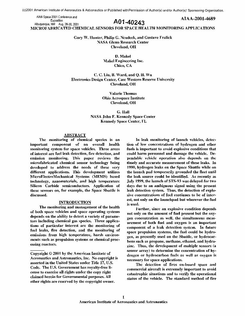
The design of the PdCr sensor is shown in Fig-ure 1. The structure includes a Pd alloy Schottkydiode and resistor, a temperature detector, and aheater all incorporated in the same chip. Alsoshown is a picture of the packaged sensor. The re-sponse of the Schottky diodes was determined bymeasuring the diode's reverse current.
The sensor microfabrication allows the sensorpackage to have minimal size, weight, and powerconsumption and thus to be placed in a number oflocations. Hardware and software ("Smart" elec-tronics) have also been interfaced with the sensor to
provide signal conditioning and control. The overallapproach is to determine the magnitude and posi-tion of a leak in a region by correlating the signalfrom a number of these small sensor packages withelectronics.
This complete hydrogen detection system (atwo sensor chip with "Smart" electronics) has flownon the STS 95 mission of the Space Shuttle(launched 10-98) and again on STS 96 (launched 5-99). The hydrogen detection system was installed inthe aft compartment of the Shuttle Orbiter and usedto monitor the hydrogen concentration in that re-gion. Presently, a mass spectrometer monitors thehydrogen concentration in the aft compartment be-fore launch, while after launch "grab" bottles areused. Before flight, the inside of these "grab" bot-tles are at vacuum. During flight, the "grab" bottlesare pyrotechnically opened for a brief period andthe gas in the aft compartment is captured in thebottle. Several of these bottles are opened at differ-ent times during the takeoff and their contents areused to determine the time profile of the gases in theaft chamber. However, this information is onlyavailable after the flight.
P d - A L L O Y S C H O T T K Y' D I O D E C O N N E C T O R S
a) 2.2 mm
HEATERC O N N E C T O R
T E M P E R A T U R EDETECTOR
H E A T E RC O N N E C T O R
Figure 1. a) Schematic diagram of the silicon- basedhydrogen sensor. The Pd alloy Schottky diode (rec-tangular regions) resides symmetrically on eitherside of a heater and temperature detector. The Pdalloy resistor is included for high concentrationmeasurements, b) Picture of the packaged sensor.
American Institute of Aeronautics and Astronautics
(c)2001 American Institute of Aeronautics & Astronautics or Published with Permission of Author(s) and/or Author(s)' Sponsoring Organization.
The data of the STS 95 mission has been ana-lyzed. The response of the hydrogen sensors wascompared to that of the mass spectrometer andthose obtained by the "grab" bottles. Duringground monitoring, the hydrogen sensor (Schottkydiode) response was compared with that of the massspectrometer during fueling (not shown). As fuelfirst entered the system, a small increase in hydro-gen concentration was observed with both the hy-drogen sensor and mass spectrometer. Overall, thehydrogen sensor response paralleled that of themass spectrometer but with a larger signal andquicker response time perhaps due to the relativelocation of the sensor with respect to the hydrogensource.
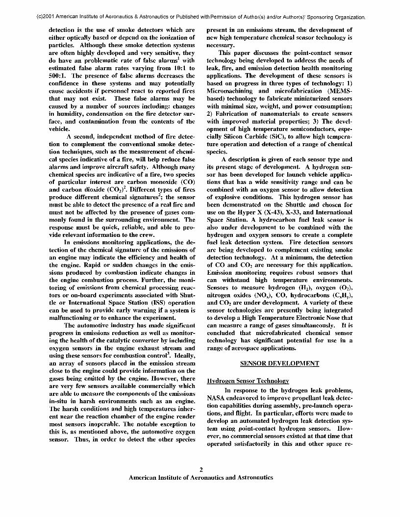
The hydrogen sensor response during launchand in-flight is shown in Figure 2. No sensor re-sponse is seen until the cut-off of the main engine.Near this time, a spike in the hydrogen concentra-tion is observed which decreases with time back tobaseline levels. These results are qualitatively con-sistent with the leakage of very small concentrationsof unburnt fuel from the engines into the aft com-partment after engine cut-off. These observationsalso qualitatively agree with those derived fromanalyzing the contents of the grab bottles. More-over, the advantage of this microsensor approach isthat the monitoring of the aft compartment is con-tinuous and, in principle, could be used for real-time health monitoring of the vehicle in flight.
600
<400
iO 300
g200ooo 100
Main Engine Cut Off (MECO)
200 600 800400
TIME(SEC)
Figure 2. The response of PdCr Schottky diode sen-sor during the launch of the STS-95 Shuttle Mis-sion.
A second project where the MEMS-basedhydrogen sensor technology is currently being ap-plied is on the International Space Station. Newtechnologies are being developed for the Interna-
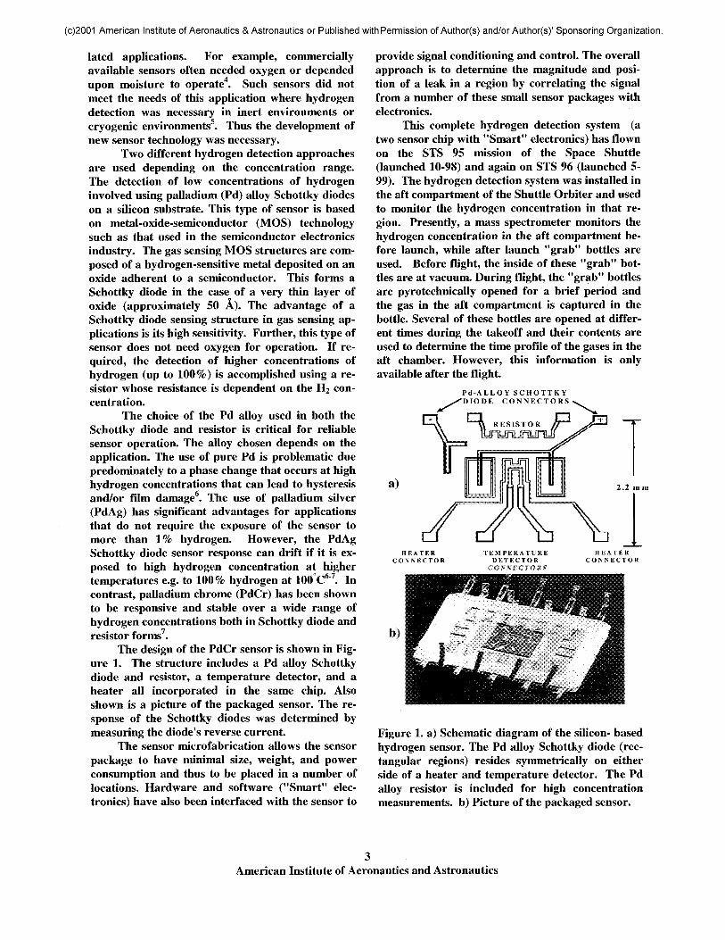
tional Space Station regenerative life support sys-tem. One such system being developed by NASA foroxygen generation involves the electrolysis of re-claimed water. For this application a system con-sisting of triple redundant hydrogen sensors tomonitor the product oxygen for trace hydrogen hasbeen developed as a system safety monitoring sensorsystem. A prototype version of the sensor system isshown in Figure 3. For this application the sensorsmust be capable of detecting low concentrations ofhydrogen (0 to 4%) in a pure oxygen backgroundand relative humidity up to 100%. The sensorsmust have a fast response time (under 10 seconds)and have calibrations that are stable for severalmonths to years. Engineering development versionsof the sensors have been demonstrated for NASAand work is currently underway developing a flight-qualified version of the sensor system.
Figure 3. Prototype, triple redundant hydrogensensor system developed for use as part of the oxy-gen generator system for the International SpaceStation.
The hydrogen sensors are also being used fortrace hydrogen detection during flight operationsfor the X-43 (Hyper-X) program. For this applica-tion the sensors must operate in a variable pressureenvironment (0.1 to 1 atm) and be capable of pro-ducing an output signal displaying the total concen-tration of hydrogen. The background gas environ-ment is inert. For this application, a pressure com-pensated version of the sensor system was developedthat is capable of hydrogen concentration meas-urements (0 to 5%) at high altitude and with rapidtransitions in altitude. The sensor was included onboth the captive carry test (4-01) and first flight(6-01). Data from these missions will be publishedas available in a future publication.
American Institute of Aeronautics and Astronautics
(c)2001 American Institute of Aeronautics & Astronautics or Published with Permission of Author(s) and/or Author(s)' Sponsoring Organization.
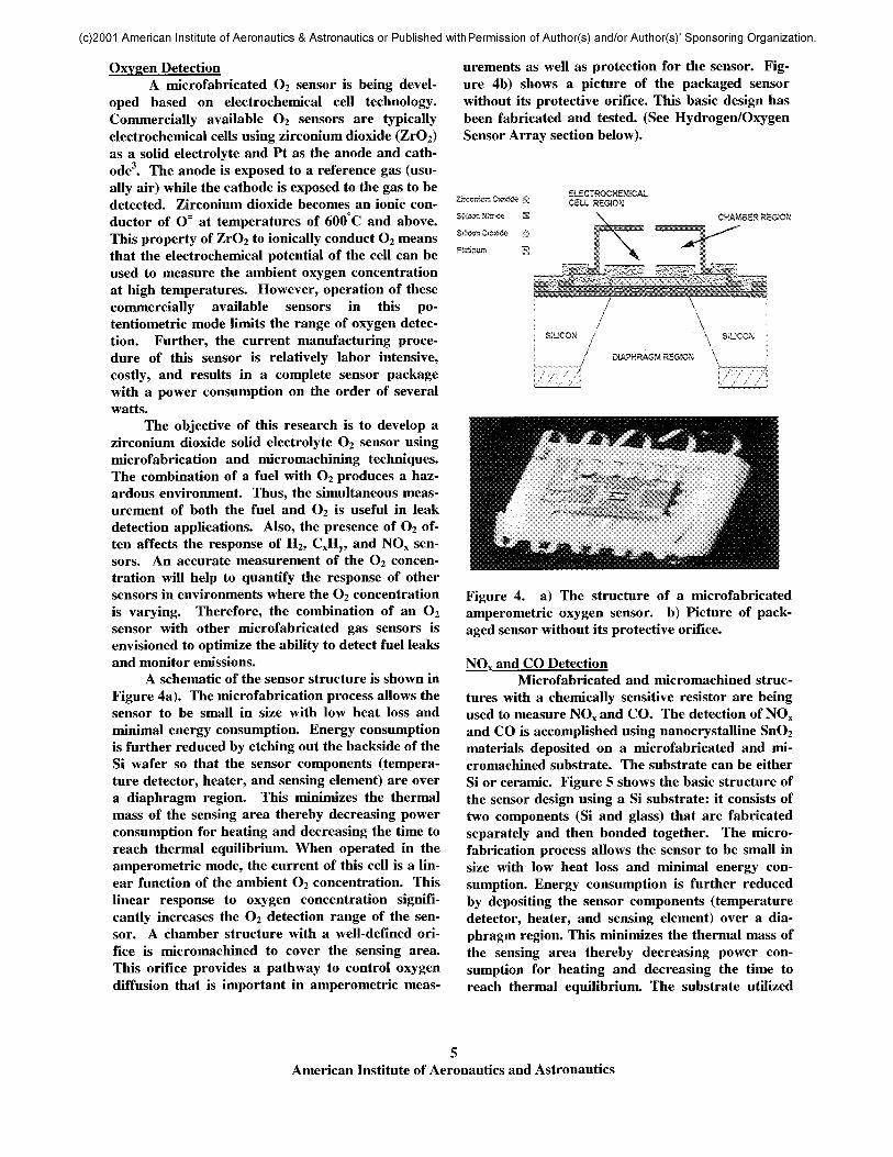
Oxygen DetectionA microfabricated O2 sensor is being devel-
oped based on electrochemical cell technology.Commercially available O2 sensors are typicallyelectrochemical cells using zirconium dioxide (ZrO2)as a solid electrolyte and Pt as the anode and cath-ode3. The anode is exposed to a reference gas (usu-ally air) while the cathode is exposed to the gas to bedetected. Zirconium dioxide becomes an ionic con-ductor of O= at temperatures of 600 C and above.This property of ZrO2 to ionically conduct O2 meansthat the electrochemical potential of the cell can beused to measure the ambient oxygen concentrationat high temperatures. However, operation of thesecommercially available sensors in this po-tentiometric mode limits the range of oxygen detec-tion. Further, the current manufacturing proce-dure of this sensor is relatively labor intensive,costly, and results in a complete sensor packagewith a power consumption on the order of severalwatts.
The objective of this research is to develop azirconium dioxide solid electrolyte O2 sensor usingmicrofabrication and micromachining techniques.The combination of a fuel with O2 produces a haz-ardous environment. Thus, the simultaneous meas-urement of both the fuel and O2 is useful in leakdetection applications. Also, the presence of O2 of-ten affects the response of H2, CxHy, and NOX sen-sors. An accurate measurement of the O2 concen-tration will help to quantify the response of othersensors in environments where the O2 concentrationis varying. Therefore, the combination of an O2sensor with other microfabricated gas sensors isenvisioned to optimize the ability to detect fuel leaksand monitor emissions.
A schematic of the sensor structure is shown inFigure 4a). The microfabrication process allows thesensor to be small in size with low heat loss andminimal energy consumption. Energy consumptionis further reduced by etching out the backside of theSi wafer so that the sensor components (tempera-ture detector, heater, and sensing element) are overa diaphragm region. This minimizes the thermalmass of the sensing area thereby decreasing powerconsumption for heating and decreasing the time toreach thermal equilibrium. When operated in theamperometric mode, the current of this cell is a lin-ear function of the ambient O2 concentration. Thislinear response to oxygen concentration signifi-cantly increases the O2 detection range of the sen-sor. A chamber structure with a well-defined ori-fice is micromachined to cover the sensing area.This orifice provides a pathway to control oxygendiffusion that is important in amperometric meas-
urements as well as protection for the sensor. Fig-ure 4b) shows a picture of the packaged sensorwithout its protective orifice. This basic design hasbeen fabricated and tested. (See Hydrogen/OxygenSensor Array section below).
£L£CTR0CH£liCAlCELL RSG10M
CHAMBER REGION
j SILICON /
I / DIAPHRAGM RBSIOM \I.,,,....,.,....,..,,,._,,/ \5: ".'• ' ' ' " / . ' % i
SIUCOM
Figure 4. a) The structure of a microfabricatedamperometric oxygen sensor, b) Picture of pack-aged sensor without its protective orifice.
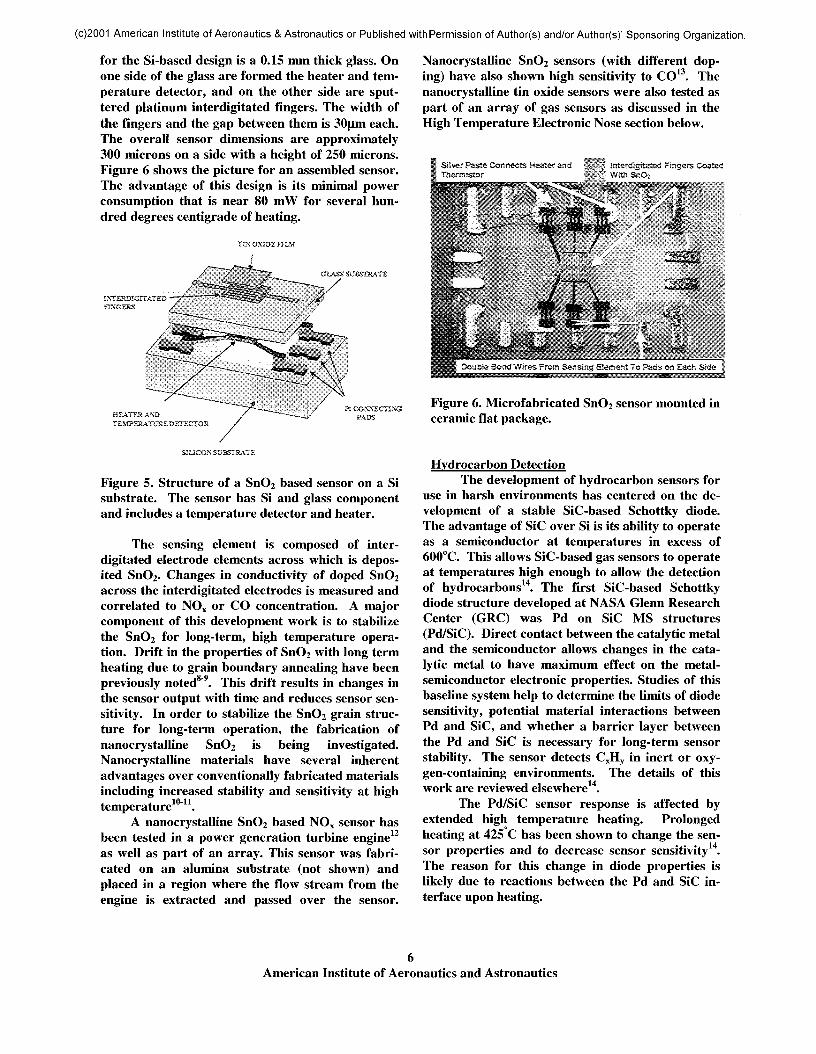
and CO DetectionMicrofabricated and micromachined struc-
tures with a chemically sensitive resistor are beingused to measure NOX and CO. The detection of NOXand CO is accomplished using nanocrystalline SnO2
materials deposited on a microfabricated and mi-cromachined substrate. The substrate can be eitherSi or ceramic. Figure 5 shows the basic structure ofthe sensor design using a Si substrate: it consists oftwo components (Si and glass) that are fabricatedseparately and then bonded together. The micro-fabrication process allows the sensor to be small insize with low heat loss and minimal energy con-sumption. Energy consumption is further reducedby depositing the sensor components (temperaturedetector, heater, and sensing element) over a dia-phragm region. This minimizes the thermal mass ofthe sensing area thereby decreasing power con-sumption for heating and decreasing the time toreach thermal equilibrium. The substrate utilized
American Institute of Aeronautics and Astronautics
(c)2001 American Institute of Aeronautics & Astronautics or Published with Permission of Author(s) and/or Author(s)' Sponsoring Organization.
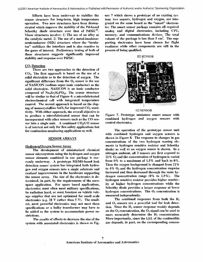
for the Si-based design is a 0.15 mm thick glass. Onone side of the glass are formed the heater and tem-perature detector, and on the other side are sput-tered platinum interdigitated fingers. The width ofthe fingers and the gap between them is 30(im each.The overall sensor dimensions are approximately300 microns on a side with a height of 250 microns.Figure 6 shows the picture for an assembled sensor.The advantage of this design is its minimal powerconsumption that is near 80 mW for several hun-dred degrees centigrade of heating.
TIN OXIDE FJiM
CLASS SUBSTRATE
HEATER ANBTEMPERATURE 0£T£CTQR
SIOCON SUBSTRATE
Figure 5. Structure of a SnO2 based sensor on a Sisubstrate. The sensor has Si and glass componentand includes a temperature detector and heater.
The sensing element is composed of inter-digitated electrode elements across which is depos-ited SnO2. Changes in conductivity of doped SnO2across the interdigitated electrodes is measured andcorrelated to NOX or CO concentration. A majorcomponent of this development work is to stabilizethe SnO2 for long-term, high temperature opera-tion. Drift in the properties of SnO2 with long termheating due to grain boundary annealing have beenpreviously noted8"9. This drift results in changes inthe sensor output with time and reduces sensor sen-sitivity. In order to stabilize the SnO2 grain struc-ture for long-term operation, the fabrication ofnanocrystalline SnO2 is being investigated.Nanocrystalline materials have several inherentadvantages over conventionally fabricated materialsincluding increased stability and sensitivity at hightemperature10"11.
A nanocrystalline SnO2 based NOX sensor hasbeen tested in a power generation turbine engine12
as well as part of an array. This sensor was fabri-cated on an alumina substrate (not shown) andplaced in a region where the flow stream from theengine is extracted and passed over the sensor.
Nanocrystalline SnO2 sensors (with different dop-ing) have also shown high sensitivity to CO13. Thenanocrystalline tin oxide sensors were also tested aspart of an array of gas sensors as discussed in theHigh Temperature Electronic Nose section below.
Interdtgttated Fingers CoatedWitfc SnO2
Double Bond Wires From Sensing: Element To Pads :on Sac!* Side
Figure 6. Microfabricated SnO2 sensor mounted inceramic flat package.
Hydrocarbon DetectionThe development of hydrocarbon sensors for
use in harsh environments has centered on the de-velopment of a stable SiC-based Schottky diode.The advantage of SiC over Si is its ability to operateas a semiconductor at temperatures in excess of600°C. This allows SiC-based gas sensors to operateat temperatures high enough to allow the detectionof hydrocarbons14. The first SiC-based Schottkydiode structure developed at NASA Glenn ResearchCenter (GRC) was Pd on SiC MS structures(Pd/SiC). Direct contact between the catalytic metaland the semiconductor allows changes in the cata-lytic metal to have maximum effect on the metal-semiconductor electronic properties. Studies of thisbaseline system help to determine the limits of diodesensitivity, potential material interactions betweenPd and SiC, and whether a barrier layer betweenthe Pd and SiC is necessary for long-term sensorstability. The sensor detects CxHy in inert or oxy-gen-containing environments. The details of thiswork are reviewed elsewhere14.
The Pd/SiC sensor response is affected byextended high temperature heating. Prolongedheating at 425 C has been shown to change the sen-sor properties and to decrease sensor sensitivity14.The reason for this change in diode properties islikely due to reactions between the Pd and SiC in-terface upon heating.
American Institute of Aeronautics and Astronautics
(c)2001 American Institute of Aeronautics & Astronautics or Published with Permission of Author(s) and/or Author(s)' Sponsoring Organization.
Efforts have been underway to stabilize thesensor structure for long-term, high temperatureoperation. Two new structures have been demon-strated which improve the stability of the Pd-basedSchottky diode structure over that of Pd/SiC15.These structures involve: 1) The use of an alloy asthe catalytic metal. 2) The use of a metal-insulator-semiconductor (MIS) structure where the "insula-tor" stabilizes the interface and is also reactive tothe gases of interest. Preliminary testing of both ofthese structures suggests significantly improvedstability and response over Pd/SiC.
CO? DetectionThere are two approaches to the detection of
CO2. The first approach is based on the use of asolid electrolyte as in the detection of oxygen. Thesignificant difference from the O2 sensor is the useof NASICON (sodium super ionic conductor) as thesolid electrolyte. NASICON is an ionic conductorcomposed of Na3Zr2Si2POi2. The sensor structurewill be similar to that of Figure 4: a microfabricatedelectrochemical cell with integrated temperaturecontrol. The second approach is based on the dop-ing of nanocrystalline SnO2 for improved CO2 sensi-tivity. With either approach, the overall objective isto produce a microfabricated sensor that can beincorporated with other sensors such as the CO sen-sor into a single unit. A combined CO2/CO sensoris of interest not only for fire safety applications butfor combustion monitoring applications as well.
SENSOR ARRAYS
Hydrogen/Oxygen Sensor ArrayThe development of miniaturized chemical
sensor microsystems using the hydrogen and oxygensensor elements combined in one package is cur-rently underway. A prototype MEMS-based leakdetection sensor system has integrated both hydro-gen and oxygen sensors into a single substrate andrealized improvements in the hardware supportingthe sensor array. The size of the electronics is de-termined, in part, by the requirements of the aero-space application. For space based applications,electronics must often meet military specifications,be radiation hard, or must function on vehicle volt-age supplies that are not optimized for small scaleelectronics (e.g. 28 V rather than 5 V). The small-est, most powerful electronics may not meet thesespecifications or a bulky transformer may have tobe added to the system to accommodate power re-strictions.
The results of efforts to decrease the size of thesystem with associated electronics is shown in Fig-
ure 7 which shows a prototype of an existing sys-tem: two sensors, hydrogen and oxygen, are inte-grated on the same board as the "smart" electron-ics. The smart sensor package contains all requiredanalog and digital electronics, including CPU,memory, and communications devices. The totalvolume of the package is less than 5 cm3. The sup-porting electronics have been chosen for flightreadiness while other components are still in theprocess of being qualified.
O2 SENSORFigure 7. Prototype miniature smart sensor withcombined hydrogen and oxygen sensors withcontrol electronics.
The operation of the prototype sensor unitwith combined hydrogen and oxygen sensors isshown in Figure 8. The response to changes in gasconcentrations of the two hydrogen sensing ele-ments (a hydrogen sensitive resistor and Schottkydiode) as well as an oxygen sensor is shown. In anitrogen ambient, all 3 sensors are first exposed to21% O2 and the concentration of hydrogen is variedfrom 0% to a maximum of 1.5% and back to 0%.Then the oxygen background is changed from 21%to 4% O2 and the hydrogen concentration step wiseincreased and then decreased through the same hy-drogen concentration range (0% to 1.5%). Thehydrogen sensitive resistor provides higher sensitiv-ity at higher hydrogen concentrations while theSchottky diode provides a larger response at lowerhydrogen concentrations. The O2 concentration ismeasured independently.
The combined responses from both the H2
and O2 sensors are a powerful tool for leak detec-tion. Since the H2 sensor response weakly dependson the O2 concentration, the O2 signal can be used tomore accurately determine the H2 concentration.More importantly, since the LEL of the combustiblegas depends, in part, on the corresponding concen-
American Institute of Aeronautics and Astronautics
(c)2001 American Institute of Aeronautics & Astronautics or Published with Permission of Author(s) and/or Author(s)' Sponsoring Organization.
tration of the oxidizer, knowing the relative ratio ofthe gases is necessary to determine if an explosivecondition exists. Using the sensor system shown inFigure 7, information is provided on both the con-centration of the combustible gas (H2) and the oxi-dizer (O2) simultaneously and thus a more accuratedetermination of the hazardous conditions can bedetermined.
4500 n
4000:
3500 :
3000:
i 2500 :
SIG
NA
L
3 §
1500;
1000:
500:
n -
..........................................................................̂Switch from 21% 02 to 4% 02 H2
/ DIODE
02 SENSOR
H2 DIODE-̂
H2 RESISTOR -
0.5% HZ
Tji
i~*~
1.0% h
r^
— *~"/
b ri/ ^»ifc
1.0% H2 i f~ 1.0% H2
i_ •, >^~-̂ i^^ , r .
1 !0.5% HZ-! : 0.5% H;
• -̂̂ 'y^ j^
/ H2 RESISTOR
|
j 02 SENSOR
100 200 300TIME (sec)
400 500 600
Figure 8. The response of a hydrogen (2 sensors)and oxygen detection system with associated elec-tronics to multiple concentrations of hydrogen in achanging oxygen ambient.
This work demonstrates the beneficial use ofmultiple sensors with different detection mecha-nisms yielding improved information about thechemical constituents of an environment. It is envi-sioned that this multiple microsensor approach,combined with MEMS-based fabrication of thecomponent parts, can allow the placement of sen-sors in a number of locations to better determine thesafety of the region of interest. The long-term objec-tives of this work in the Second GenerationSpaceliner program is to produce a fuel/oxygen sen-sor array with the surface area of postage stampwhich includes the power and communications sup-port structure to make it a stand-alone system. Thefuel of this Second Generation vehicle could be hy-drogen or hydrocarbon based; therefore both hy-drogen and hydrocarbon detection are necessary.Combined with an oxygen sensor, this complete sys-tem can have the ability to detect fuel leaks with thecorresponding oxygen level from a wide range ofpropulsion systems.
Further, in order to have a postage stampsized system increased miniaturization of the exist-
ing microfabricated technology is necessary. Thiswork has begun as seen in Figure 9. Figure 9 showsthe oxygen sensor design of Figure 4 compared to anew, smaller version of the sensor. This new designis expected to have capabilities of the present designbut also significantly reducing the size and powerconsumption.
Figure 9. Comparison of the size of two oxygen sen-sors produced using different processing ap-proaches. A smaller sensor size with less power con-sumption is necessary for integrated, postage-stampsized sensor systems envisioned for the next genera-tion of vehicles.
Fire Detection ArrayThe detection of CO and CO2 are two of the
major chemical species produced with the onset ofmost fires. While the presence of other species(such as hydrocarbons) are of interest1"2, significantchemical species information regarding the indica-tion of a fire can be obtained by measuring the ratioof concentrations of CO to CO2 as well as their rateof change.
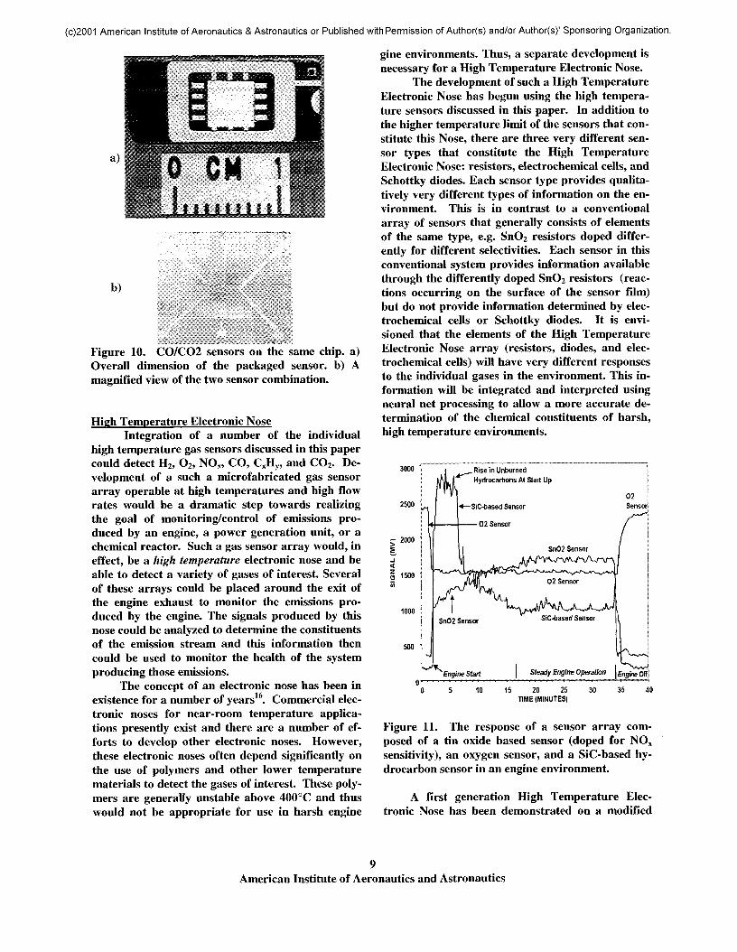
Efforts are under way to produce a CO/CO2detector on a chip. Figure 10 shows an early ver-sion of the sensor based on SnO2 used to detect bothCO and CO2 with different doping used to improveselectivity. Figure lOa shows the relative dimen-sions of the sensor while Figure lOb show a magni-fied view of the two sensors. An indentation in thesensor area in Figure lOb is due the diaphragm un-der the sensors formed with micromachining. Test-ing of this and other combined CO/CO2 sensorcombination continues. The major technical issuesrevolve around processing of the CO2 sensor. Theseinclude deposition problems associated with theNASICON based CO2 sensor and selectivity issuesfor the SnO2 based CO2 sensor.
8American Institute of Aeronautics and Astronautics
(c)2001 American Institute of Aeronautics & Astronautics or Published with Permission of Author(s) and/or Author(s)' Sponsoring Organization.
b)
Figure 10. CO/CO2 sensors on the same chip, a)Overall dimension of the packaged sensor, b) Amagnified view of the two sensor combination.
High Temperature Electronic NoseIntegration of a number of the individual
high temperature gas sensors discussed in this papercould detect H2, O2, NOX, CO, CxHy, and CO2. De-velopment of a such a microfabricated gas sensorarray operable at high temperatures and high flowrates would be a dramatic step towards realizingthe goal of monitoring/control of emissions pro-duced by an engine, a power generation unit, or achemical reactor. Such a gas sensor array would, ineffect, be a high temperature electronic nose and beable to detect a variety of gases of interest. Severalof these arrays could be placed around the exit ofthe engine exhaust to monitor the emissions pro-duced by the engine. The signals produced by thisnose could be analyzed to determine the constituentsof the emission stream and this information thencould be used to monitor the health of the systemproducing those emissions.
The concept of an electronic nose has been inexistence for a number of years16. Commercial elec-tronic noses for near-room temperature applica-tions presently exist and there are a number of ef-forts to develop other electronic noses. However,these electronic noses often depend significantly onthe use of polymers and other lower temperaturematerials to detect the gases of interest. These poly-mers are generally unstable above 400°C and thuswould not be appropriate for use in harsh engine
gine environments. Thus, a separate development isnecessary for a High Temperature Electronic Nose.
The development of such a High TemperatureElectronic Nose has begun using the high tempera-ture sensors discussed in this paper. In addition tothe higher temperature limit of the sensors that con-stitute this Nose, there are three very different sen-sor types that constitute the High TemperatureElectronic Nose: resistors, electrochemical cells, andSchottky diodes. Each sensor type provides qualita-tively very different types of information on the en-vironment. This is in contrast to a conventionalarray of sensors that generally consists of elementsof the same type, e.g. SnO2 resistors doped differ-ently for different selectivities. Each sensor in thisconventional system provides information availablethrough the differently doped SnO2 resistors (reac-tions occurring on the surface of the sensor film)but do not provide information determined by elec-trochemical cells or Schottky diodes. It is envi-sioned that the elements of the High TemperatureElectronic Nose array (resistors, diodes, and elec-trochemical cells) will have very different responsesto the individual gases in the environment. This in-formation will be integrated and interpreted usingneural net processing to allow a more accurate de-termination of the chemical constituents of harsh,high temperature environments.
3000 } Rise in UnburnedHydrocarbons At Start Up
I ^>\A^VJ
Engine Off
500
15 20 25TIME (MINUTES)
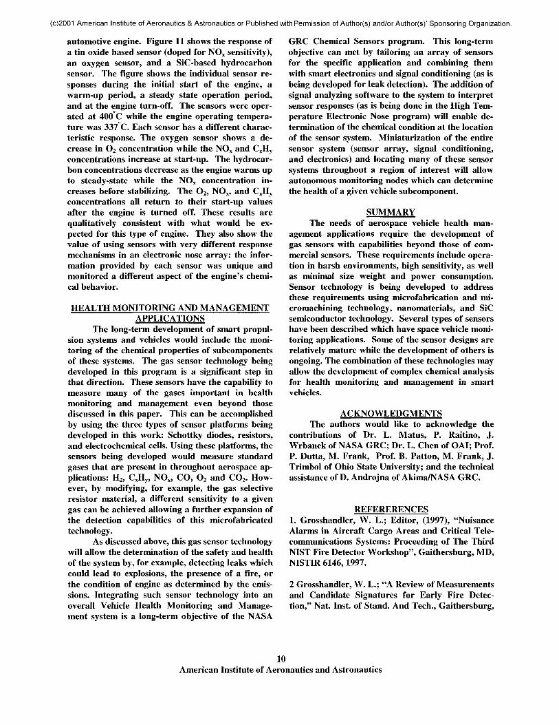
Figure 11. The response of a sensor array com-posed of a tin oxide based sensor (doped for NOX
sensitivity), an oxygen sensor, and a SiC-based hy-drocarbon sensor in an engine environment.
A first generation High Temperature Elec-tronic Nose has been demonstrated on a modified
American Institute of Aeronautics and Astronautics
(c)2001 American Institute of Aeronautics & Astronautics or Published with Permission of Author(s) and/or Author(s)' Sponsoring Organization.
automotive engine. Figure 11 shows the response ofa tin oxide based sensor (doped for NOX sensitivity),an oxygen sensor, and a SiC-based hydrocarbonsensor. The figure shows the individual sensor re-sponses during the initial start of the engine, awarm-up period, a steady state operation period,and at the engine turn-off. The sensors were oper-ated at 400 C while the engine operating tempera-ture was 337 C. Each sensor has a different charac-teristic response. The oxygen sensor shows a de-crease in O2 concentration while the NOX and CxHyconcentrations increase at start-up. The hydrocar-bon concentrations decrease as the engine warms upto steady-state while the NOX concentration in-creases before stabilizing. The O2, NOX, and CxHyconcentrations all return to their start-up valuesafter the engine is turned off. These results arequalitatively consistent with what would be ex-pected for this type of engine. They also show thevalue of using sensors with very different responsemechanisms in an electronic nose array: the infor-mation provided by each sensor was unique andmonitored a different aspect of the engine's chemi-cal behavior.
HEALTH MONITORING AND MANAGEMENTAPPLICATIONS
The long-term development of smart propul-sion systems and vehicles would include the moni-toring of the chemical properties of subcomponentsof these systems. The gas sensor technology beingdeveloped in this program is a significant step inthat direction. These sensors have the capability tomeasure many of the gases important in healthmonitoring and management even beyond thosediscussed in this paper. This can be accomplishedby using the three types of sensor platforms beingdeveloped in this work: Schottky diodes, resistors,and electrochemical cells. Using these platforms, thesensors being developed would measure standardgases that are present in throughout aerospace ap-plications: H2, CxHy, NOX, CO, O2 and CO2. How-ever, by modifying, for example, the gas selectiveresistor material, a different sensitivity to a givengas can be achieved allowing a further expansion ofthe detection capabilities of this microfabricatedtechnology.
As discussed above, this gas sensor technologywill allow the determination of the safety and healthof the system by, for example, detecting leaks whichcould lead to explosions, the presence of a fire, orthe condition of engine as determined by the emis-sions. Integrating such sensor technology into anoverall Vehicle Health Monitoring and Manage-ment system is a long-term objective of the NASA
GRC Chemical Sensors program. This long-termobjective can met by tailoring an array of sensorsfor the specific application and combining themwith smart electronics and signal conditioning (as isbeing developed for leak detection). The addition ofsignal analyzing software to the system to interpretsensor responses (as is being done in the High Tem-perature Electronic Nose program) will enable de-termination of the chemical condition at the locationof the sensor system. Miniaturization of the entiresensor system (sensor array, signal conditioning,and electronics) and locating many of these sensorsystems throughout a region of interest will allowautonomous monitoring nodes which can determinethe health of a given vehicle subcomponent.
SUMMARYThe needs of aerospace vehicle health man-
agement applications require the development ofgas sensors with capabilities beyond those of com-mercial sensors. These requirements include opera-tion in harsh environments, high sensitivity, as wellas minimal size weight and power consumption.Sensor technology is being developed to addressthese requirements using microfabrication and mi-cromachining technology, nanomaterials, and SiCsemiconductor technology. Several types of sensorshave been described which have space vehicle moni-toring applications. Some of the sensor designs arerelatively mature while the development of others isongoing. The combination of these technologies mayallow the development of complex chemical analysisfor health monitoring and management in smartvehicles.
ACKNOWLEDGMENTSThe authors would like to acknowledge the
contributions of Dr. L. Matus, P. Raitino, J.Wrbanek of NASA GRC; Dr. L. Chen of OAI; Prof.P. Dutta, M. Frank, Prof. B. Patton, M. Frank, J.Trimbol of Ohio State University; and the technicalassistance of D. Androjna of Akima/NASA GRC.
REFERERENCES1. Grosshandler, W. L.; Editor, (1997), "NuisanceAlarms in Aircraft Cargo Areas and Critical Tele-communications Systems: Proceeding of The ThirdNIST Fire Detector Workshop", Gaithersburg, MD,NISTIR 6146,1997.
2 Grosshandler, W. L.; "A Review of Measurementsand Candidate Signatures for Early Fire Detec-tion," Nat. Inst. of Stand. And Tech., Gaithersburg,
10American Institute of Aeronautics and Astronautics

(c)2001 American Institute of Aeronautics & Astronautics or Published with Permission of Author(s) and/or Author(s)' Sponsoring Organization.
MD, NISTIR 555.1995.
3. Logothetis, E. M.; "Automotive Oxygen Sen-sors", Chemical Sensor Technology, Vol. 3, N. Ya-mazoe, ed., Kodansha Ltd., pp. 89-104,1991.
4. Hunter, Gary W.; "A Survey and Analysis ofCommercially Available Hydrogen Sensors",NASA Technical Memorandum 105878, November1992.
5. Hunter, Gary W.; "A Survey and Analysis ofExperimental Hydrogen Sensors", NASA TechnicalMemorandum 106300, October 1992.
6. Hughes, R. C.; Schubert, W. K.; Zipperian, T. E.;Rodriguez, J. L.; and Plut, T. A.; "Thin Film Palla-dium and Silver Alloys and Layers for Metal-Insulator-Semiconductor Sensors", J. Appl. Phys.,vol. 62,1074,1987.
7. Hunter, G. W.; Neudeck, P. G.; Chen, L.-Y.;Makel, D. B, Liu, C. C.; and Wu, Q.H. and "AHazardous Gas Detection System for Aerospace andCommercial Applications," 34th AIAA/ASME/SAE/ASEE Joint Propulsion Conference and Ex-hibit, Cleveland, OH July 1998, Tech. Rep AIAA-98-3614,1998.
8. Ogawa, H.; Nishikawa, M.; and Abe, A.; "HallMeasurement Studies and an Electrical ConductionModel of Tin Oxide Ultrafine Particle Films", Jour-nal of Applied Physics, vol. 53, pp. 4448-4455,1988.
9. Xu, C.; Tamaki, J.; Miura, N.; and Yamazoe,N.; "Grain Size Effects on Gas Sensitivity of PorousSnO2-Based Elements", Sensors and Actuators, B,vol. 3, pp. 147-155,1991.
10. Yoo, D. J.; Tamaki, J.; Park, S. J.; Miura, N.;and Yamazoe, N.; "Effects of Thickness and Calci-nation Temperature on Tin Dioxide Sol-DerivedThin-Film Sensor", Journal of Electrochemical So-ciety, vol. 142, pp. L105-L107,1995.
11. Vogel, R.; Hoyer, P.; and Weller, H.; "Quan-tum-Sized PbS, CdS, Ag2S, Sb2S3, and Bi2S3 Parti-cles as Sensitizers for Various Nanoporous Wide-Bandgap Semiconductors", Journal of PhysicalChemistry, vol. 98, pp. 3183-3188,1994.
12 . Hunter, G. W.; Neudeck, P. G.; Fralick, G.;Liu, C. C.; Wu, Q.H.; Sawayda; S., Jin; Z.; Makel
D.B.; Liu, M.; Rauch, W.A.; and Hall, G.;, "Chemi-cal Microsensors For Aerospace Applications", Mi-crofabricated Systems and MEMS V, Proceedingsof the International Symposium, 198th Meeting ofthe Electrochemical Society, 22-27 Oct., Phoenix,AZ, pp. 126-141, 2000.
13 . Jin, Z.H.; Zhou, H. J.; Jin, Z. L.; Savinell, R.F.; and Liu, C.C.; "Application of nano-crystallineporous tin oxide thin film for CO sensing", Sensorsand Actuators B, 52 pp. 188-194,1998.
14. Chen, L.-Y.; Hunter, G. W.; Neudeck, P. G.;Knight, D.; Liu, C. C.; and Wu, Q. H.; "SiC BasedGas Sensors", in Proceedings of the Third Interna-tional Symposium on Ceramic Sensors, Anderson et.al, Editors, Electrochemical Society Inc., pp. 92-105,1996.
15. Hunter, G. W.; Neudeck, P. G.; Chen, L.-Y.;Knight, D.; Liu, C. C.; and Wu, Q. H.; "SiC-BasedSchottky Diode Gas Sensors", Proceedings of Inter-national Conference on SiC and Related Materials,Stockholm, Sweden, Sep. 1-7,1997.
16. Gardner, J. W. and Bartlett, P. N.; "A BriefHistory Of Electronic Noses", Sensors and Actua-tors, B, 18 (1-3), pp. 211-220,1994.
11American Institute of Aeronautics and Astronautics