Embed Size (px)
DESCRIPTION
Technical Specification for LT Distribution for 63 KVA Distribution Transformer
Citation preview
STORES/DB/URBAN/SMC/2011/03
Maharashtra State Electricity Distribution Company Limited
SPECIFICATION NO. STORES/DB/URBAN/SMC/2011/03
TECHNICAL SPECIFICATION
FOR
63, 100,200 KVA SMC LT DISTRIBUTION BOX with MCCBs for Urban Areas.
IN
MSEDCL
STORES/DB/URBAN/SMC/2011/03
Technical Specifications
63 /100 /200 KVA SMC L.T. DISTRIBUTION BOX with MCCBs for Urban Area
NO. STORES /DB/URBAN/SMC/2011/03
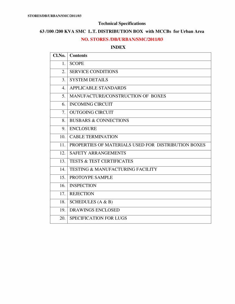
INDEX
Cl.No. Contents
1. SCOPE
2. SERVICE CONDITIONS
3. SYSTEM DETAILS
4. APPLICABLE STANDARDS
5. MANUFACTURE/CONSTRUCTION OF BOXES
6. INCOMING CIRCUIT
7. OUTGOING CIRCUIT
8. BUSBARS & CONNECTIONS
9. ENCLOSURE
10. CABLE TERMINATION
11. PROPERTIES OF MATERIALS USED FOR DISTRIBUTION BOXES
12. SAFETY ARRANGEMENTS
13. TESTS & TEST CERTIFICATES
14. TESTING & MANUFACTURING FACILITY
15. PROTOYPE SAMPLE
16. INSPECTION
17. REJECTION
18. SCHEDULES (A & B)
19. DRAWINGS ENCLOSED
20. SPECIFICATION FOR LUGS
STORES/DB/URBAN/SMC/2011/03
MAHARASHTRA STATE ELECTRICITY DISTRIBUTION COMPANY
Technical Specifications for
63/100/200 KVA SMC L.T. DISTRIBUTION BOX with M.C.C.Bs.
SPECIFICATION NO.DIST/DB/URBAN/SMC/2011/03.
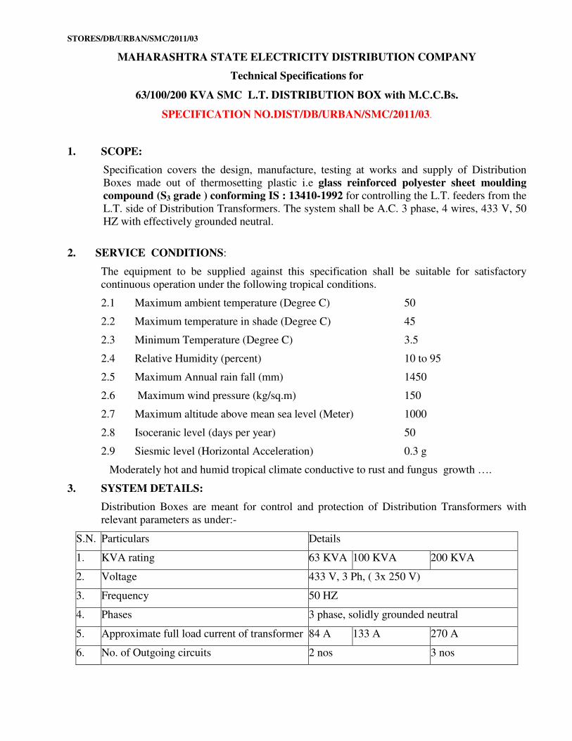
1. SCOPE:
Specification covers the design, manufacture, testing at works and supply of Distribution
Boxes made out of thermosetting plastic i.e glass reinforced polyester sheet moulding
compound (S3 grade ) conforming IS : 13410-1992 for controlling the L.T. feeders from the
L.T. side of Distribution Transformers. The system shall be A.C. 3 phase, 4 wires, 433 V, 50
HZ with effectively grounded neutral.
2. SERVICE CONDITIONS:
The equipment to be supplied against this specification shall be suitable for satisfactory
continuous operation under the following tropical conditions.
2.1 Maximum ambient temperature (Degree C) 50
2.2 Maximum temperature in shade (Degree C) 45
2.3 Minimum Temperature (Degree C) 3.5
2.4 Relative Humidity (percent) 10 to 95
2.5 Maximum Annual rain fall (mm) 1450
2.6 Maximum wind pressure (kg/sq.m) 150
2.7 Maximum altitude above mean sea level (Meter) 1000
2.8 Isoceranic level (days per year) 50
2.9 Siesmic level (Horizontal Acceleration) 0.3 g
Moderately hot and humid tropical climate conductive to rust and fungus growth ….
3. SYSTEM DETAILS:
Distribution Boxes are meant for control and protection of Distribution Transformers with
relevant parameters as under:-
S.N. Particulars Details
1. KVA rating 63 KVA 100 KVA 200 KVA
2. Voltage 433 V, 3 Ph, ( 3x 250 V)
3. Frequency 50 HZ
4. Phases 3 phase, solidly grounded neutral
5. Approximate full load current of transformer 84 A 133 A 270 A
6. No. of Outgoing circuits 2 nos 3 nos
STORES/DB/URBAN/SMC/2011/03
4. Applicable Standards:
a. IS :13947/1993 (Part 3) for Isolator (Switch Disconnector)
b. IS: 13947/1993 (Part2) (amended upto date) for L.T. MCCBs.
c. IS: 8623/1993 (amended upto date) for enclosure Box & for degree of protection
provided by enclosures of electrical equipments.
d. IS: 4237/1982 IS: 8623/1993 (amended upto date) – for general requirement of L.T.
switchgears.
e. IS 13703/1993 (Part I & II amended upto date) for HRC Fuse Base and HRC Fuse
Link.
f. IS: 13410: 1992 - Sheet Moulding compound (SMC) Enclosure.
g. IS: 13411: 1992 - Glass Reinforced Polyester Dough Moulding Compounds.
5. MANUFACTURE/CONSTRUCTION OF BOXES:
a. Distribution Boxes shall have Isolator (Switch Disconnector) and HRC fuse base with
links on incoming circuit and single pole MCCBs & Link Disconnector on outgoing
circuits with necessary interconnecting Bus Bars/ Links.
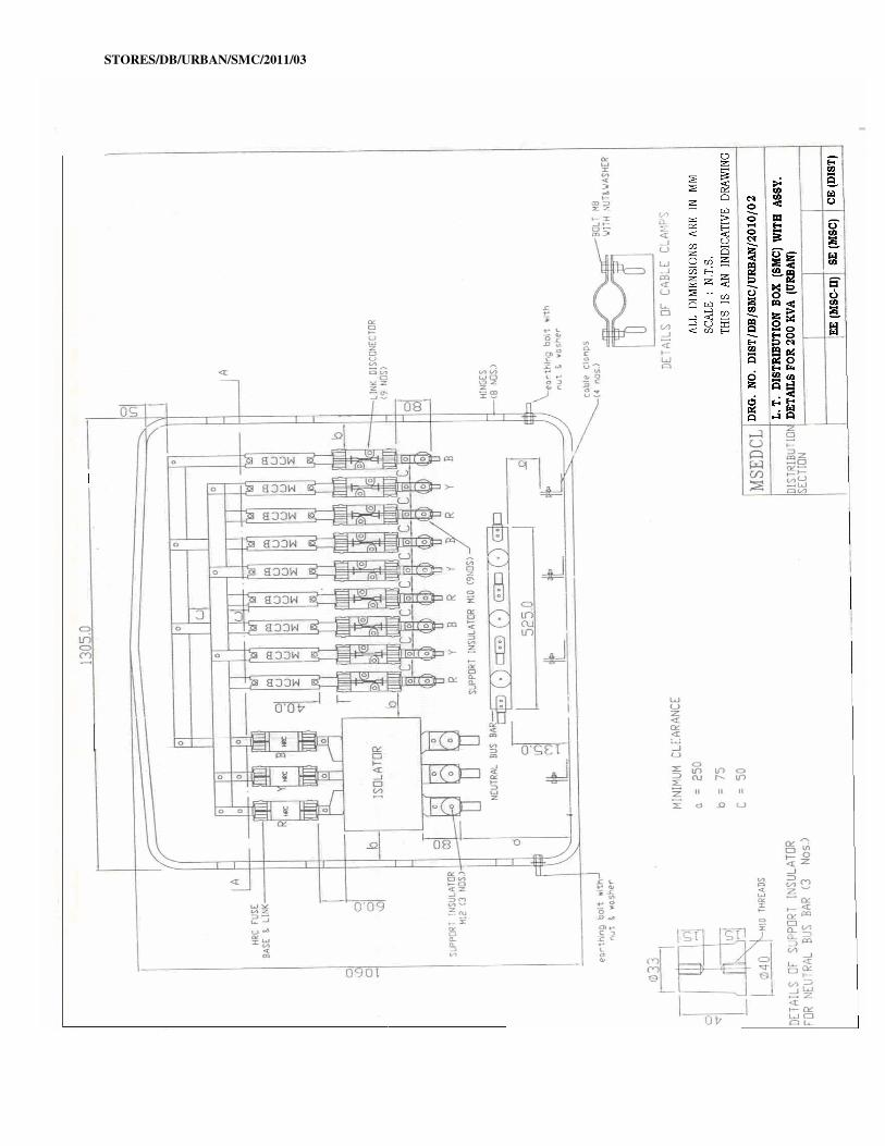
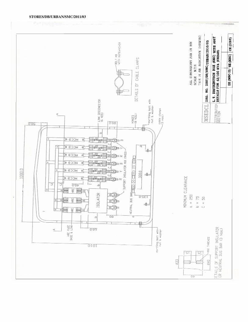
b. Standard General Arrangement of Isolators, HRC fuse base with links, MCCBs, Link
Disconnector, Neutral Links, Bus Bars, connecting links, Cable termination
arrangement etc inside the Box is shown in the enclosed drawing No. Dist
/DB/SMC/URBAN/2010/05 for 63/100 KVA and Drawing No. Dist / DB/SMC/
URBAN/2010/02 for 200 KVA distribution boxes.
6. INCOMING CIRCUIT –
6.1 Isolator (Switch Disconnector) -
Each distribution box shall have one triple pole Isolator (Switch Disconnector), conforming
to relevant IS and MSEDCL specification. The bidder shall indicate makes and types of
offered isolator in GTP. The successful bidder shall submit Type Test Report of the Isolator
as specified in Cl. No. 13(C) and 13.6 for approval of CE(STORES) before commencement
of supply. The makes of Switch disconnector provided in the Distribution Box to be supplied
shall be as the mentioned in the GTP of detailed purchased order from MSEDCL.
The Isolator should be front operated triple pole type. The casing of Isolator shall be
non-tracking, heat resistant insulating material of Dough Moulding Compound (DMC) of
D3 Grade as per IS:13411/1992, no separate enclosure is required. Isolator Base should
withstand the breaking capacity of 80 kA. To extinguish the arc immediately in isolators, in
each phase archutes with minimum 12 strips shall be provided.
The isolator should be front operated triple pole type. If the casing of Isolator is of non-
tracking, heat resistant insulating material, no separate enclosure is required. The isolator
shall be robust in construction and easy for operation. The handle of the isolator should be
detachable easily for security purpose while working on L.T. circuits.
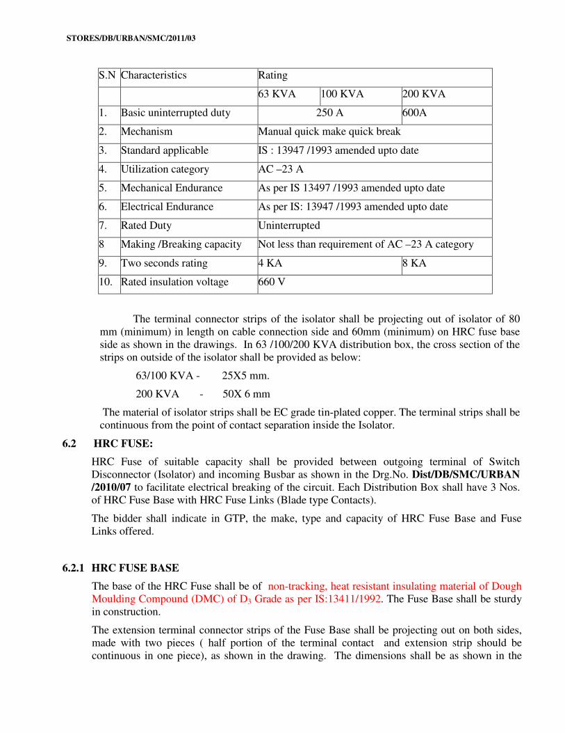
The characteristics of Isolator shall be as follows:
STORES/DB/URBAN/SMC/2011/03
S.N Characteristics Rating
63 KVA 100 KVA 200 KVA
1. Basic uninterrupted duty 250 A 600A
2. Mechanism Manual quick make quick break
3. Standard applicable IS : 13947 /1993 amended upto date
4. Utilization category AC –23 A
5. Mechanical Endurance As per IS 13497 /1993 amended upto date
6. Electrical Endurance As per IS: 13947 /1993 amended upto date
7. Rated Duty Uninterrupted
8 Making /Breaking capacity Not less than requirement of AC –23 A category
9. Two seconds rating 4 KA 8 KA
10. Rated insulation voltage 660 V
The terminal connector strips of the isolator shall be projecting out of isolator of 80
mm (minimum) in length on cable connection side and 60mm (minimum) on HRC fuse base
side as shown in the drawings. In 63 /100/200 KVA distribution box, the cross section of the
strips on outside of the isolator shall be provided as below:
63/100 KVA - 25X5 mm.
200 KVA - 50X 6 mm
The material of isolator strips shall be EC grade tin-plated copper. The terminal strips shall be
continuous from the point of contact separation inside the Isolator.
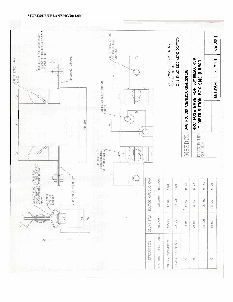
6.2 HRC FUSE:
HRC Fuse of suitable capacity shall be provided between outgoing terminal of Switch
Disconnector (Isolator) and incoming Busbar as shown in the Drg.No. Dist/DB/SMC/URBAN
/2010/07 to facilitate electrical breaking of the circuit. Each Distribution Box shall have 3 Nos.
of HRC Fuse Base with HRC Fuse Links (Blade type Contacts).
The bidder shall indicate in GTP, the make, type and capacity of HRC Fuse Base and Fuse
Links offered.
6.2.1 HRC FUSE BASE
The base of the HRC Fuse shall be of non-tracking, heat resistant insulating material of Dough
Moulding Compound (DMC) of D3 Grade as per IS:13411/1992. The Fuse Base shall be sturdy
in construction.
The extension terminal connector strips of the Fuse Base shall be projecting out on both sides,
made with two pieces ( half portion of the terminal contact and extension strip should be
continuous in one piece), as shown in the drawing. The dimensions shall be as shown in the
STORES/DB/URBAN/SMC/2011/03
drawing. The material for both strips shall be Silver Plated EC Grade copper. HRC Fuse Base
and fuse link should have withstand breaking capacity of 80 kA.
HRC Fuse base shall be suitable for fuse of 200A for 63/100 KVA distribution box and 400 A
for 200 KVA distribution box.
6.2.2 HRC FUSE LINK
The HRC Fuse Links shall be sturdy in construction of “Din Type”. Breaking Capacity shall be
80 kA. For fault indication red pop up indicator should come out instantly on fusing.
Manufacturer’s name, current rating, breaking capacity and type shall be marked on HRC fuse
link.
HRC Fuse link Current rating for 63/100 /200 KVA distribution box shall be as follows:
63 KVA - 100 A
100 KVA - 160 A
200 KVA - 315 A.
The successful bidder shall submit Type Test Report of the HRC fuse base and HRC fuse link
as specified in Cl. No. 13(C) and 13.8 for approval of CE (STORES) before commencement of
supply. The makes of HRC fuse base with link provided in the Distribution Box to be supplied
shall be as the mentioned in the GTP of detailed purchased order from MSEDCL.
7. OUTGOING CIRCUITS:
7.1 MCCBs
Each distribution box shall have 6 nos. of single-pole MCCBs in 63 KVA /100 KVA Box and
9 nos of single-pole MCCBs in 200 KVA box to protect outgoing circuits. MCCB shall be
conforming to this specification. The bidder shall indicate the makes and types of MCCBs
offered in GTP. The successful bidder shall submit Type Test Report of the MCCB as
specified in Cl. No. 13(C) and 13.7 for approval of CE (STORES) before commencement of
supply. The makes of MCCBs provided in the Distribution Box to be supplied shall be as the
mentioned in the GTP of detailed purchased order from MSEDCL.
The colour of MCCBs for 63/100 /200 distribution box shall be as follows:
63 KVA - Brown
100 KVA - Dark admiral gray
200 KVA - Black
MCCB shall have quick make quick break mechanism. Making of MCCB shall only be
manual but breaking of MCCBs shall be electrical as well as manual.
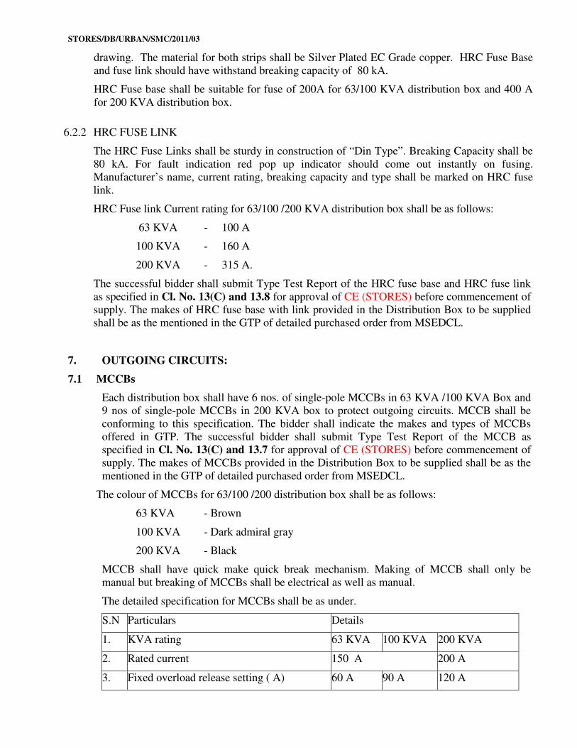
The detailed specification for MCCBs shall be as under.
S.N Particulars Details
1. KVA rating 63 KVA 100 KVA 200 KVA
2. Rated current 150 A 200 A
3. Fixed overload release setting ( A) 60 A 90 A 120 A
STORES/DB/URBAN/SMC/2011/03
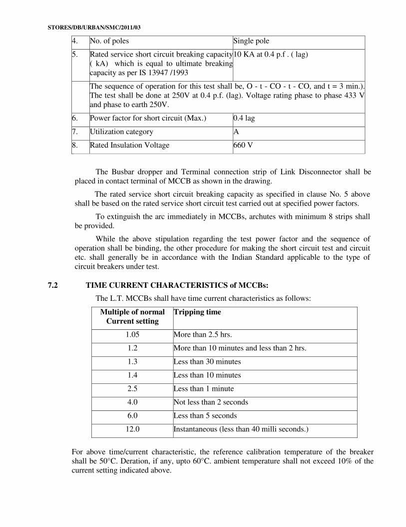
4. No. of poles Single pole
5. Rated service short circuit breaking capacity
( kA) which is equal to ultimate breaking
capacity as per IS 13947 /1993
10 KA at 0.4 p.f . ( lag)
The sequence of operation for this test shall be, O - t - CO - t - CO, and t = 3 min.).
The test shall be done at 250V at 0.4 p.f. (lag). Voltage rating phase to phase 433 V
and phase to earth 250V.
6. Power factor for short circuit (Max.) 0.4 lag
7. Utilization category A
8. Rated Insulation Voltage 660 V
The Busbar dropper and Terminal connection strip of Link Disconnector shall be
placed in contact terminal of MCCB as shown in the drawing.
The rated service short circuit breaking capacity as specified in clause No. 5 above
shall be based on the rated service short circuit test carried out at specified power factors.
To extinguish the arc immediately in MCCBs, archutes with minimum 8 strips shall
be provided.
While the above stipulation regarding the test power factor and the sequence of
operation shall be binding, the other procedure for making the short circuit test and circuit
etc. shall generally be in accordance with the Indian Standard applicable to the type of
circuit breakers under test.
7.2 TIME CURRENT CHARACTERISTICS of MCCBs:
The L.T. MCCBs shall have time current characteristics as follows:
Multiple of normal
Current setting
Tripping time
1.05 More than 2.5 hrs.
1.2 More than 10 minutes and less than 2 hrs.
1.3 Less than 30 minutes
1.4 Less than 10 minutes
2.5 Less than 1 minute
4.0 Not less than 2 seconds
6.0 Less than 5 seconds
12.0 Instantaneous (less than 40 milli seconds.)
For above time/current characteristic, the reference calibration temperature of the breaker
shall be 50°C. Deration, if any, upto 60°C. ambient temperature shall not exceed 10% of the
current setting indicated above.
STORES/DB/URBAN/SMC/2011/03
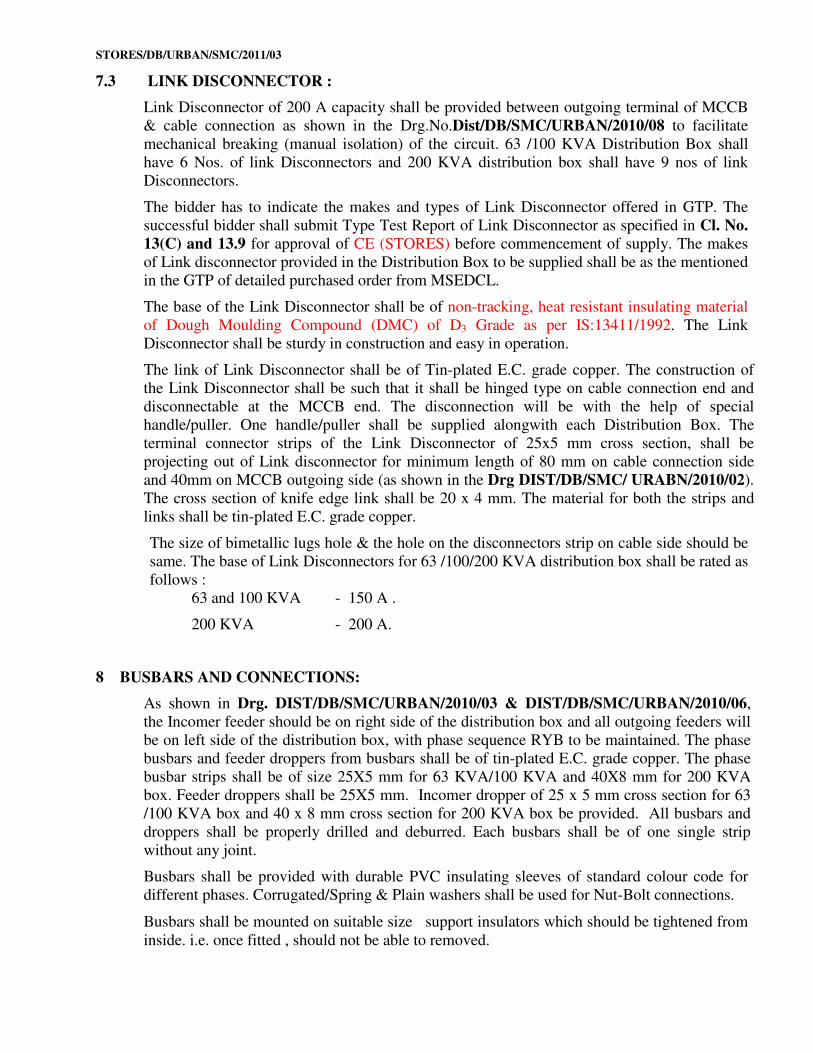
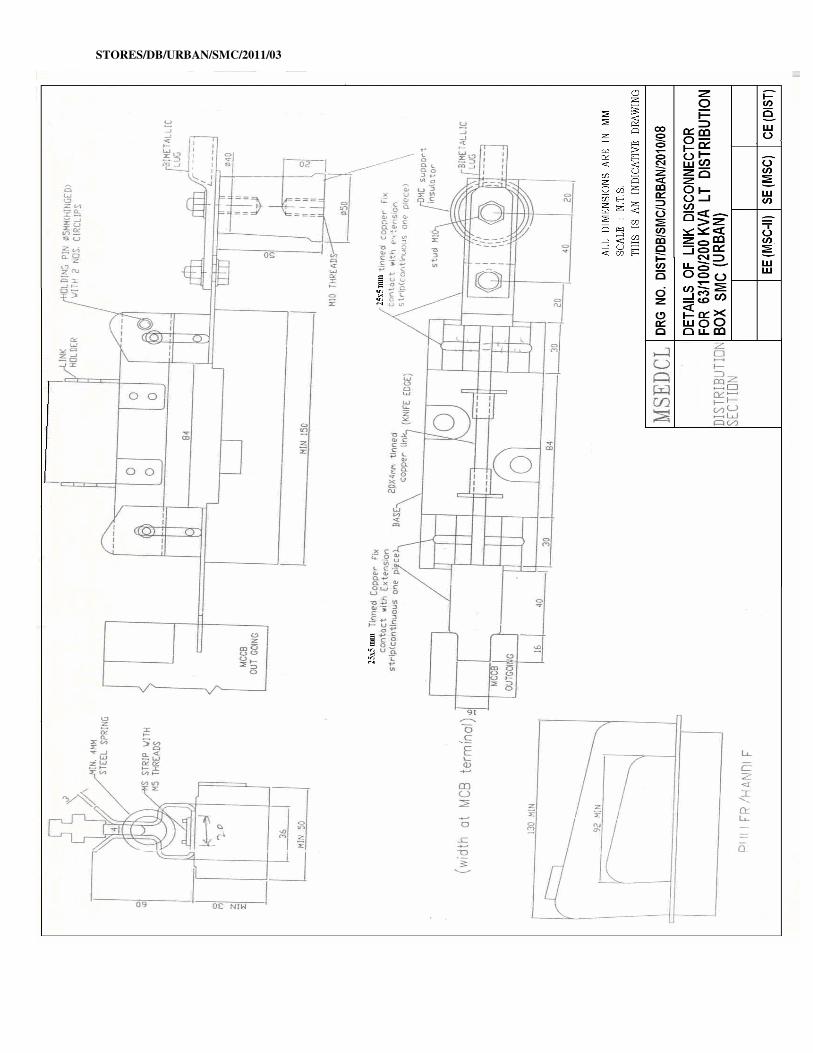
7.3 LINK DISCONNECTOR :
Link Disconnector of 200 A capacity shall be provided between outgoing terminal of MCCB
& cable connection as shown in the Drg.No.Dist/DB/SMC/URBAN/2010/08 to facilitate
mechanical breaking (manual isolation) of the circuit. 63 /100 KVA Distribution Box shall
have 6 Nos. of link Disconnectors and 200 KVA distribution box shall have 9 nos of link
Disconnectors.
The bidder has to indicate the makes and types of Link Disconnector offered in GTP. The
successful bidder shall submit Type Test Report of Link Disconnector as specified in Cl. No.
13(C) and 13.9 for approval of CE (STORES) before commencement of supply. The makes
of Link disconnector provided in the Distribution Box to be supplied shall be as the mentioned
in the GTP of detailed purchased order from MSEDCL.
The base of the Link Disconnector shall be of non-tracking, heat resistant insulating material
of Dough Moulding Compound (DMC) of D3 Grade as per IS:13411/1992. The Link
Disconnector shall be sturdy in construction and easy in operation.
The link of Link Disconnector shall be of Tin-plated E.C. grade copper. The construction of
the Link Disconnector shall be such that it shall be hinged type on cable connection end and
disconnectable at the MCCB end. The disconnection will be with the help of special
handle/puller. One handle/puller shall be supplied alongwith each Distribution Box. The
terminal connector strips of the Link Disconnector of 25x5 mm cross section, shall be
projecting out of Link disconnector for minimum length of 80 mm on cable connection side
and 40mm on MCCB outgoing side (as shown in the Drg DIST/DB/SMC/ URABN/2010/02).
The cross section of knife edge link shall be 20 x 4 mm. The material for both the strips and
links shall be tin-plated E.C. grade copper.
The size of bimetallic lugs hole & the hole on the disconnectors strip on cable side should be
same. The base of Link Disconnectors for 63 /100/200 KVA distribution box shall be rated as
follows :
63 and 100 KVA - 150 A .
200 KVA - 200 A.
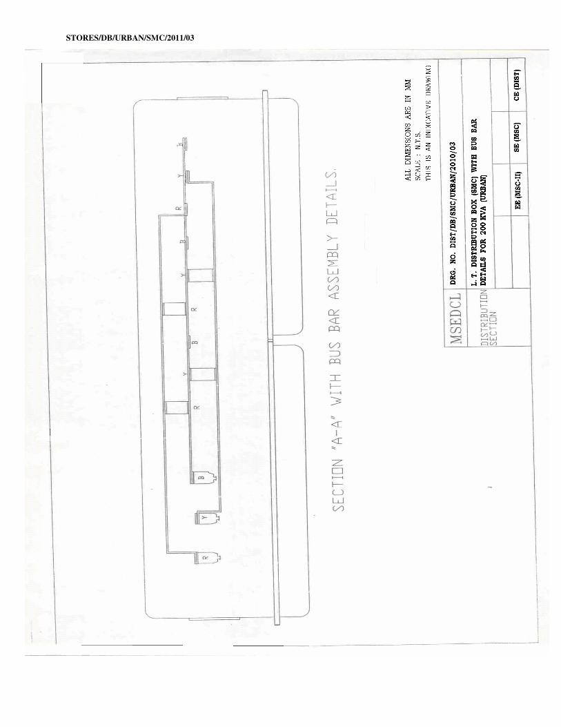
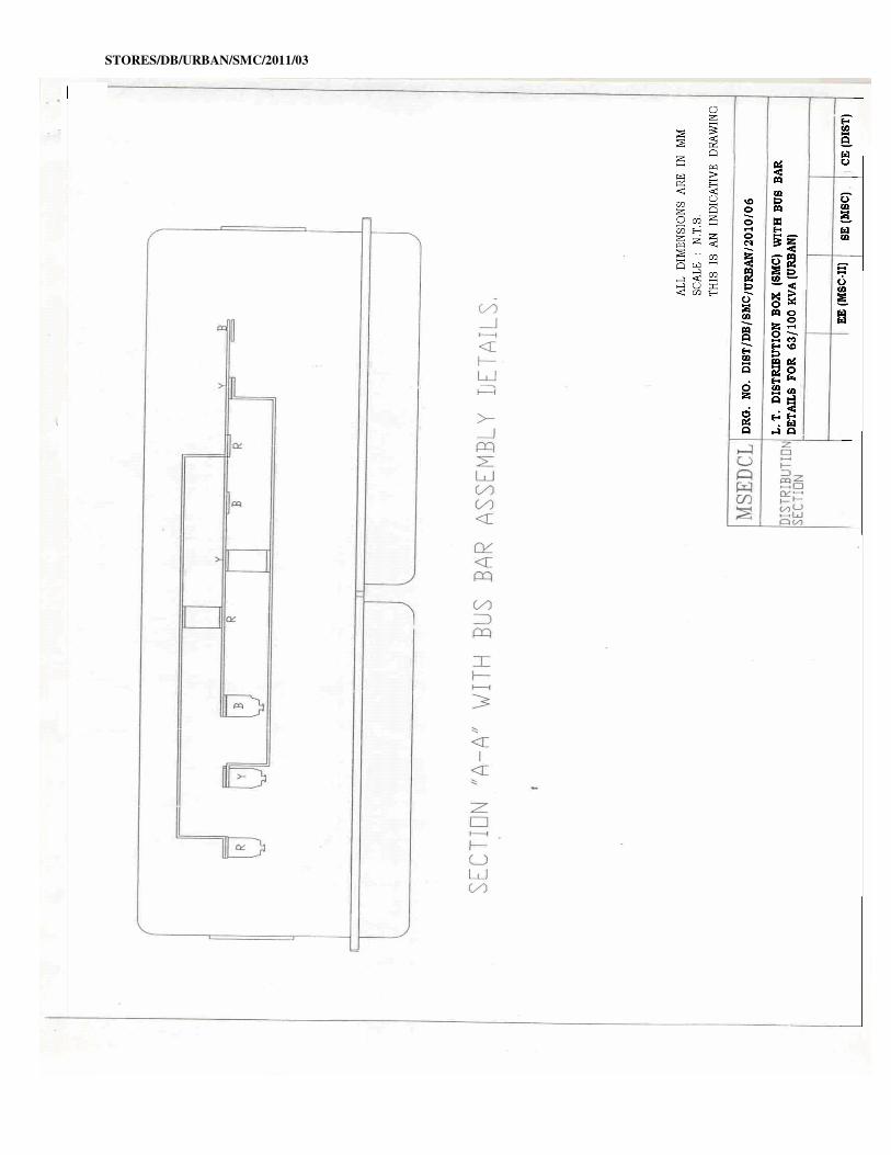
8 BUSBARS AND CONNECTIONS:
As shown in Drg. DIST/DB/SMC/URBAN/2010/03 & DIST/DB/SMC/URBAN/2010/06,
the Incomer feeder should be on right side of the distribution box and all outgoing feeders will
be on left side of the distribution box, with phase sequence RYB to be maintained. The phase
busbars and feeder droppers from busbars shall be of tin-plated E.C. grade copper. The phase
busbar strips shall be of size 25X5 mm for 63 KVA/100 KVA and 40X8 mm for 200 KVA
box. Feeder droppers shall be 25X5 mm. Incomer dropper of 25 x 5 mm cross section for 63
/100 KVA box and 40 x 8 mm cross section for 200 KVA box be provided. All busbars and
droppers shall be properly drilled and deburred. Each busbars shall be of one single strip
without any joint.
Busbars shall be provided with durable PVC insulating sleeves of standard colour code for
different phases. Corrugated/Spring & Plain washers shall be used for Nut-Bolt connections.
Busbars shall be mounted on suitable size support insulators which should be tightened from
inside. i.e. once fitted , should not be able to removed.
STORES/DB/URBAN/SMC/2011/03
Minimum clearances, wherever shown, shall be as per General Arrangement Drawing
enclosed with this specification. Other clearances shall be as per requirement of IS: 4237/1982
amended upto date.
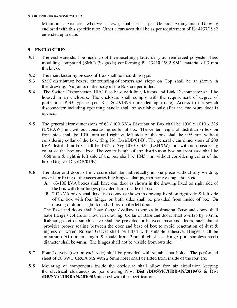
9 ENCLOSURE:
9.1 The enclosure shall be made up of thermosetting plastic i.e. glass reinforced polyester sheet
moulding compound (SMC) (S3 grade) conforming IS: 13410-1992 SMC material of 3 mm
thickness.
9.2 The manufacturing process of Box shall be moulding type.
9.3 SMC distribution boxes, the rounding of corners and slope on Top shall be as shown in
the drawing. No joints in the body of the Box are permitted.
9.4 The Switch Disconnector, HRC fuse base with link, Kitkats and Link Disconnector shall be
housed in an enclosure. The enclosure shall comply with the requirement of degree of
protection IP-33 type as per IS – 8623/1993 (amended upto date). Access to the switch
disconnector including operating handle shall be available only after the enclosure door is
opened.
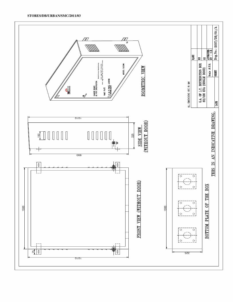
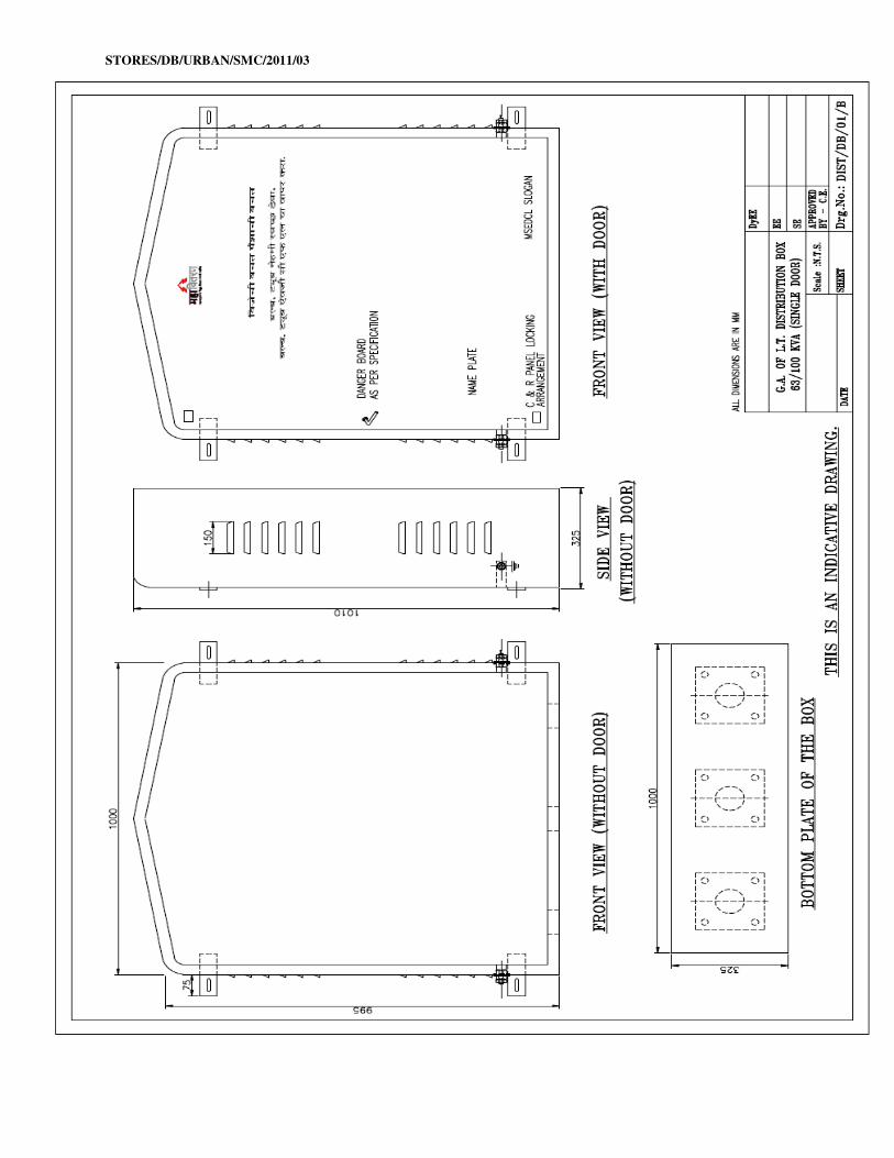
9.5 The general clear dimensions of 63 / 100 KVA Distribution Box shall be 1000 x 1010 x 325
(LXHXW)mm. without considering collor of box. The center height of distribution box on
front side shall be 1010 mm and right & left side of the box shall be 995 mm without
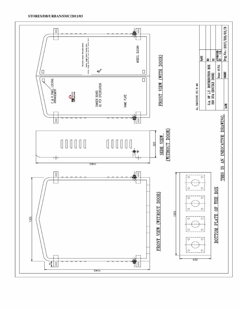
considering collar of the box. (Drg No. Dist/DB/01/B). The general clear dimensions of 200
kVA distribution box shall be 1305 x Avg.1050 x 325 (LXHXW) mm without considering
collar of the box and door. The center height of the distribution box on front side shall be
1060 mm & right & left side of the box shall be 1045 mm without considering collar of the
box (Drg No. Dist/DB/01/B).
9.6 The Base and doors of enclosure shall be individually in one piece without any welding,
except for fixing of the accessories like hinges, clamps, mounting clamps, bolts etc.
A. 63/100 kVA boxes shall have one door as shown in the drawing fixed on right side of
the box with four hinges provided from inside of box.
B. 200 kVA boxes shall have two doors as shown in drawing fixed on right side & left side
of the box with four hinges on both sides shall be provided from inside of box. On
closing of doors, right door shall rest on the left door.
The Base and doors shall have flange / collars as shown in drawing. Base and doors shall
have flange / collars as shown in drawing. Collar of Base and doors shall overlap by 10mm.
Rubber gasket of suitable size shall be provided in between base and doors, such that it provides proper sealing between the door and base of box to avoid penetration of dust &
ingress of water. Rubber Gasket shall be fitted with suitable adhesive. Hinges shall be
minimum 50 mm in length & made from 2mm thick sheet. Hinge pin (stainless steel)
diameter shall be 4mm. The hinges shall not be visible from outside.
9.7 Four Louvers (two on each side) shall be provided with suitable nut bolts. The perforated
sheet of 20 SWG CRCA MS with 2.5mm holes shall be fitted from inside of the louvers.
9.8 Mounting of components inside the enclosure shall allow free air circulation keeping
the electrical clearances as per drawing Nos. Dist /DB/SMC/URBAN/2010/05 & Dist
/DB/SMC/URBAN/2010/02 attached with the specification.
STORES/DB/URBAN/SMC/2011/03
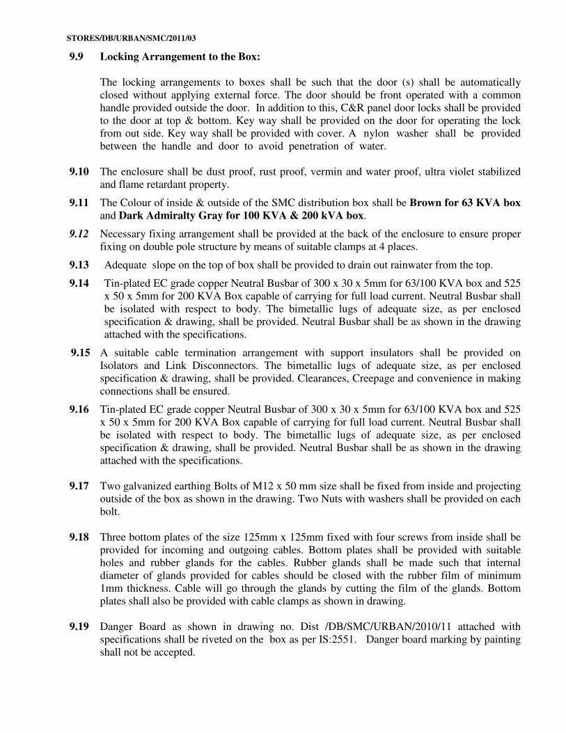
9.9 Locking Arrangement to the Box:
The locking arrangements to boxes shall be such that the door (s) shall be automatically
closed without applying external force. The door should be front operated with a common
handle provided outside the door. In addition to this, C&R panel door locks shall be provided
to the door at top & bottom. Key way shall be provided on the door for operating the lock
from out side. Key way shall be provided with cover. A nylon washer shall be provided
between the handle and door to avoid penetration of water.
9.10 The enclosure shall be dust proof, rust proof, vermin and water proof, ultra violet stabilized
and flame retardant property.
9.11 The Colour of inside & outside of the SMC distribution box shall be Brown for 63 KVA box
and Dark Admiralty Gray for 100 KVA & 200 kVA box.
9.12 Necessary fixing arrangement shall be provided at the back of the enclosure to ensure proper
fixing on double pole structure by means of suitable clamps at 4 places.
9.13 Adequate slope on the top of box shall be provided to drain out rainwater from the top.
9.14 Tin-plated EC grade copper Neutral Busbar of 300 x 30 x 5mm for 63/100 KVA box and 525
x 50 x 5mm for 200 KVA Box capable of carrying for full load current. Neutral Busbar shall
be isolated with respect to body. The bimetallic lugs of adequate size, as per enclosed
specification & drawing, shall be provided. Neutral Busbar shall be as shown in the drawing
attached with the specifications.
9.15 A suitable cable termination arrangement with support insulators shall be provided on
Isolators and Link Disconnectors. The bimetallic lugs of adequate size, as per enclosed
specification & drawing, shall be provided. Clearances, Creepage and convenience in making
connections shall be ensured.
9.16 Tin-plated EC grade copper Neutral Busbar of 300 x 30 x 5mm for 63/100 KVA box and 525
x 50 x 5mm for 200 KVA Box capable of carrying for full load current. Neutral Busbar shall
be isolated with respect to body. The bimetallic lugs of adequate size, as per enclosed
specification & drawing, shall be provided. Neutral Busbar shall be as shown in the drawing
attached with the specifications.
9.17 Two galvanized earthing Bolts of M12 x 50 mm size shall be fixed from inside and projecting
outside of the box as shown in the drawing. Two Nuts with washers shall be provided on each
bolt.
9.18 Three bottom plates of the size 125mm x 125mm fixed with four screws from inside shall be
provided for incoming and outgoing cables. Bottom plates shall be provided with suitable
holes and rubber glands for the cables. Rubber glands shall be made such that internal
diameter of glands provided for cables should be closed with the rubber film of minimum
1mm thickness. Cable will go through the glands by cutting the film of the glands. Bottom
plates shall also be provided with cable clamps as shown in drawing.
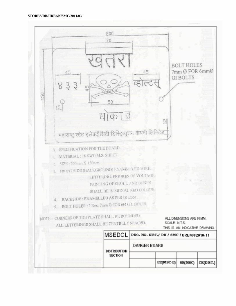
9.19 Danger Board as shown in drawing no. Dist /DB/SMC/URBAN/2010/11 attached with
specifications shall be riveted on the box as per IS:2551. Danger board marking by painting
shall not be accepted.
STORES/DB/URBAN/SMC/2011/03
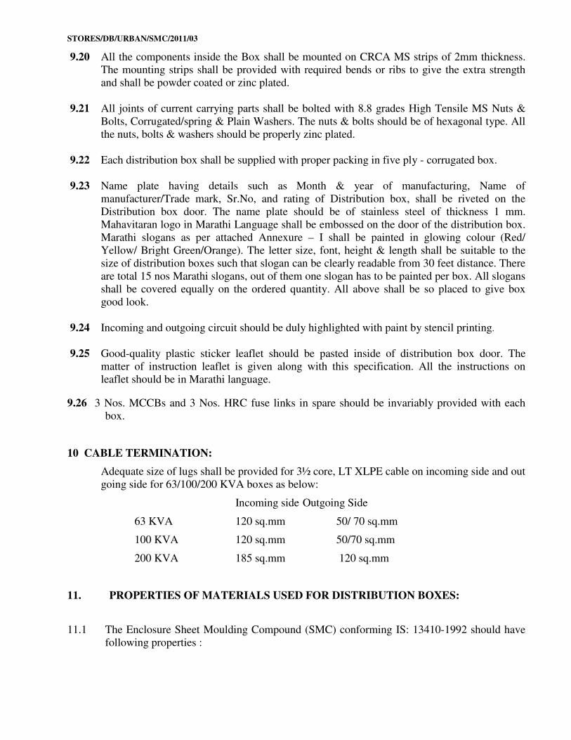
9.20 All the components inside the Box shall be mounted on CRCA MS strips of 2mm thickness.
The mounting strips shall be provided with required bends or ribs to give the extra strength
and shall be powder coated or zinc plated.
9.21 All joints of current carrying parts shall be bolted with 8.8 grades High Tensile MS Nuts &
Bolts, Corrugated/spring & Plain Washers. The nuts & bolts should be of hexagonal type. All
the nuts, bolts & washers should be properly zinc plated.
9.22 Each distribution box shall be supplied with proper packing in five ply - corrugated box.
9.23 Name plate having details such as Month & year of manufacturing, Name of
manufacturer/Trade mark, Sr.No, and rating of Distribution box, shall be riveted on the
Distribution box door. The name plate should be of stainless steel of thickness 1 mm.
Mahavitaran logo in Marathi Language shall be embossed on the door of the distribution box.
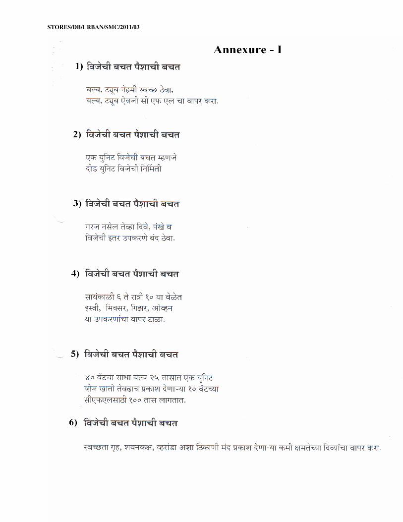
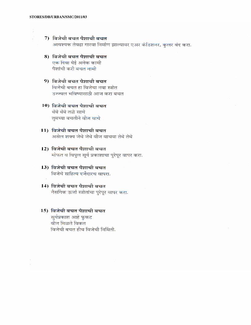
Marathi slogans as per attached Annexure – I shall be painted in glowing colour (Red/
Yellow/ Bright Green/Orange). The letter size, font, height & length shall be suitable to the
size of distribution boxes such that slogan can be clearly readable from 30 feet distance. There
are total 15 nos Marathi slogans, out of them one slogan has to be painted per box. All slogans
shall be covered equally on the ordered quantity. All above shall be so placed to give box
good look.
9.24 Incoming and outgoing circuit should be duly highlighted with paint by stencil printing.
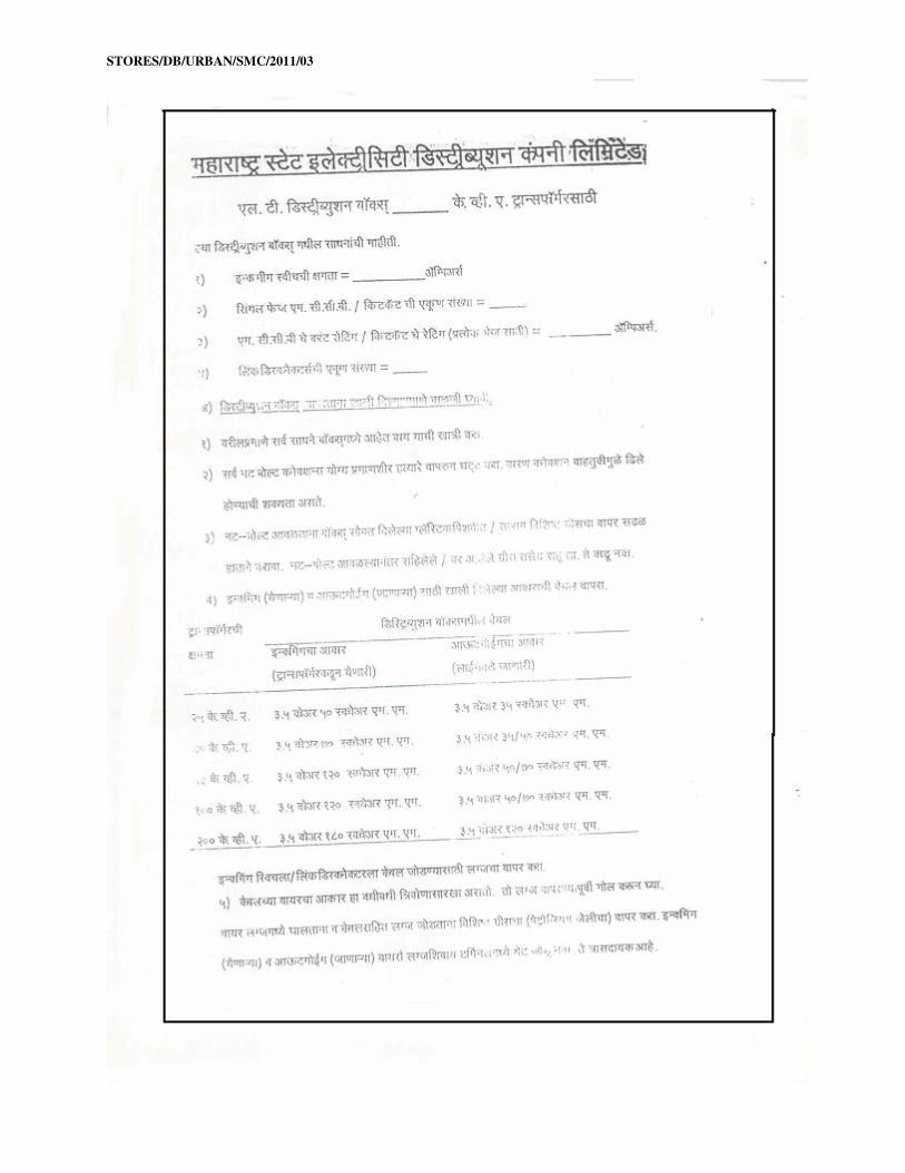
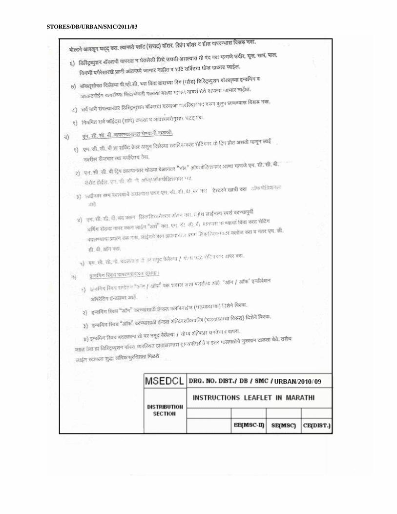
9.25 Good-quality plastic sticker leaflet should be pasted inside of distribution box door. The
matter of instruction leaflet is given along with this specification. All the instructions on
leaflet should be in Marathi language.
9.26 3 Nos. MCCBs and 3 Nos. HRC fuse links in spare should be invariably provided with each
box.
10 CABLE TERMINATION:
Adequate size of lugs shall be provided for 3½ core, LT XLPE cable on incoming side and out
going side for 63/100/200 KVA boxes as below:
Incoming side Outgoing Side
63 KVA 120 sq.mm 50/ 70 sq.mm
100 KVA 120 sq.mm 50/70 sq.mm
200 KVA 185 sq.mm 120 sq.mm
11. PROPERTIES OF MATERIALS USED FOR DISTRIBUTION BOXES:
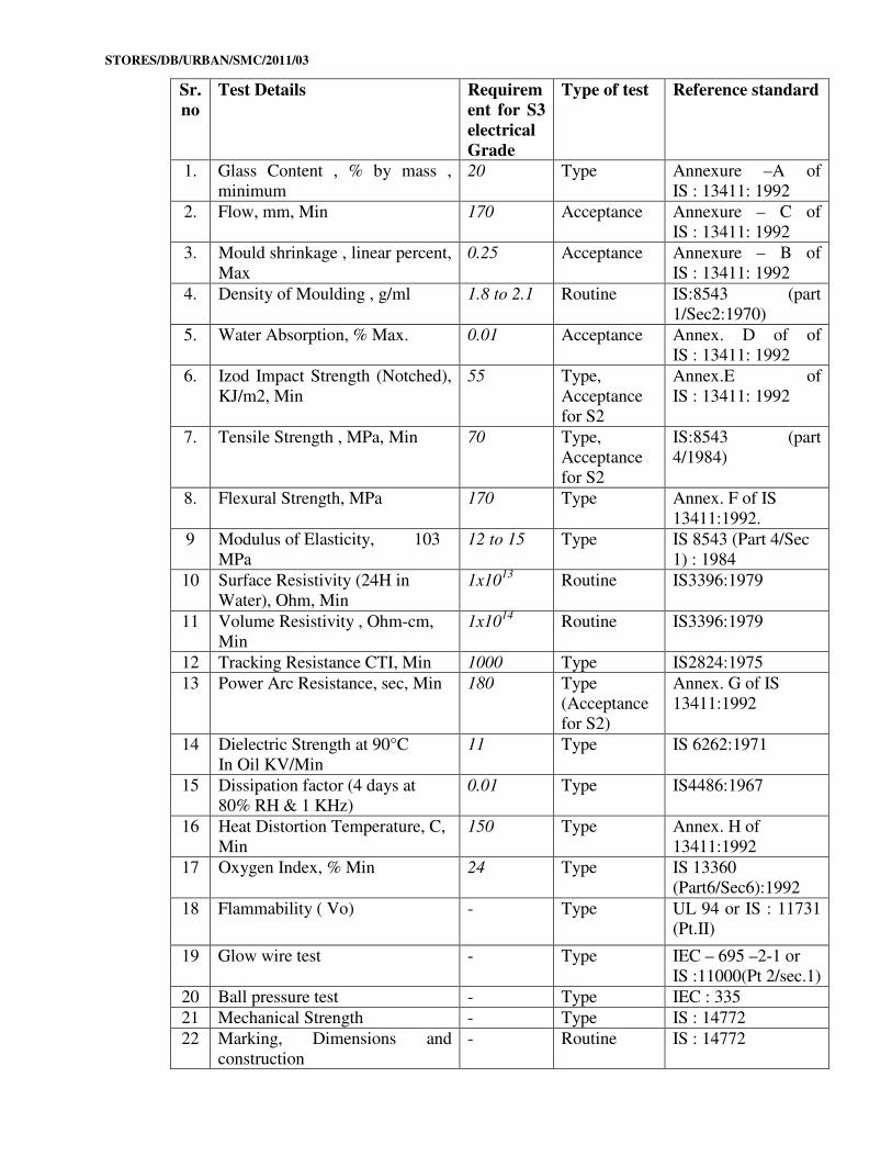
11.1 The Enclosure Sheet Moulding Compound (SMC) conforming IS: 13410-1992 should have
following properties :
STORES/DB/URBAN/SMC/2011/03
Sr.
no
Test Details Requirem
ent for S3
electrical
Grade
Type of test Reference standard
1. Glass Content , % by mass ,
minimum
20 Type Annexure –A of
IS : 13411: 1992
2. Flow, mm, Min 170 Acceptance Annexure – C of
IS : 13411: 1992
3. Mould shrinkage , linear percent,
Max
0.25 Acceptance Annexure – B of
IS : 13411: 1992
4. Density of Moulding , g/ml 1.8 to 2.1 Routine IS:8543 (part
1/Sec2:1970)
5. Water Absorption, % Max. 0.01 Acceptance Annex. D of of
IS : 13411: 1992
6. Izod Impact Strength (Notched),
KJ/m2, Min
55 Type,
Acceptance
for S2
Annex.E of
IS : 13411: 1992
7. Tensile Strength , MPa, Min 70 Type,
Acceptance
for S2
IS:8543 (part
4/1984)
8. Flexural Strength, MPa 170 Type Annex. F of IS
13411:1992.
9 Modulus of Elasticity, 103
MPa
12 to 15 Type IS 8543 (Part 4/Sec
1) : 1984
10 Surface Resistivity (24H in
Water), Ohm, Min
1x10¹³
Routine IS3396:1979
11 Volume Resistivity , Ohm-cm,
Min
1x10¹⁴
Routine IS3396:1979
12 Tracking Resistance CTI, Min 1000 Type IS2824:1975
13 Power Arc Resistance, sec, Min 180 Type
(Acceptance
for S2)
Annex. G of IS
13411:1992
14 Dielectric Strength at 90°C
In Oil KV/Min
11 Type IS 6262:1971
15 Dissipation factor (4 days at
80% RH & 1 KHz)
0.01 Type IS4486:1967
16 Heat Distortion Temperature, C,
Min
150 Type Annex. H of
13411:1992
17 Oxygen Index, % Min 24 Type IS 13360
(Part6/Sec6):1992
18 Flammability ( Vo) - Type UL 94 or IS : 11731
(Pt.II)
19 Glow wire test - Type IEC – 695 –2-1 or
IS :11000(Pt 2/sec.1)
20 Ball pressure test - Type IEC : 335
21 Mechanical Strength - Type IS : 14772
22 Marking, Dimensions and
construction
- Routine IS : 14772
STORES/DB/URBAN/SMC/2011/03
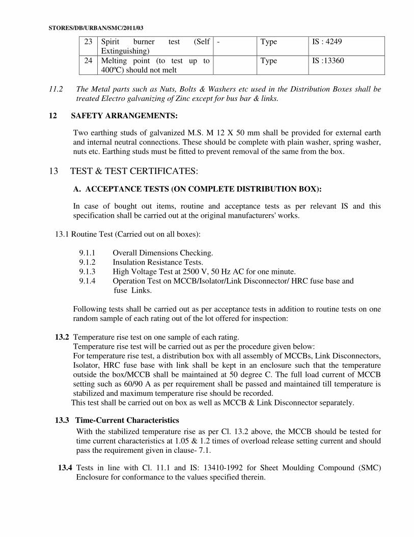
23 Spirit burner test (Self
Extinguishing)
- Type IS : 4249
24 Melting point (to test up to
400ºC) should not melt
Type IS :13360
11.2 The Metal parts such as Nuts, Bolts & Washers etc used in the Distribution Boxes shall be
treated Electro galvanizing of Zinc except for bus bar & links.
12 SAFETY ARRANGEMENTS:
Two earthing studs of galvanized M.S. M 12 X 50 mm shall be provided for external earth
and internal neutral connections. These should be complete with plain washer, spring washer,
nuts etc. Earthing studs must be fitted to prevent removal of the same from the box.
13 TEST & TEST CERTIFICATES:
A. ACCEPTANCE TESTS (ON COMPLETE DISTRIBUTION BOX):
In case of bought out items, routine and acceptance tests as per relevant IS and this
specification shall be carried out at the original manufacturers' works.
13.1 Routine Test (Carried out on all boxes):
9.1.1 Overall Dimensions Checking.
9.1.2 Insulation Resistance Tests.
9.1.3 High Voltage Test at 2500 V, 50 Hz AC for one minute.
9.1.4 Operation Test on MCCB/Isolator/Link Disconnector/ HRC fuse base and
fuse Links.
Following tests shall be carried out as per acceptance tests in addition to routine tests on one
random sample of each rating out of the lot offered for inspection:
13.2 Temperature rise test on one sample of each rating.
Temperature rise test will be carried out as per the procedure given below:
For temperature rise test, a distribution box with all assembly of MCCBs, Link Disconnectors,
Isolator, HRC fuse base with link shall be kept in an enclosure such that the temperature
outside the box/MCCB shall be maintained at 50 degree C. The full load current of MCCB
setting such as 60/90 A as per requirement shall be passed and maintained till temperature is
stabilized and maximum temperature rise should be recorded.
This test shall be carried out on box as well as MCCB & Link Disconnector separately.
13.3 Time-Current Characteristics
With the stabilized temperature rise as per Cl. 13.2 above, the MCCB should be tested for
time current characteristics at 1.05 & 1.2 times of overload release setting current and should
pass the requirement given in clause- 7.1.
13.4 Tests in line with Cl. 11.1 and IS: 13410-1992 for Sheet Moulding Compound (SMC)
Enclosure for conformance to the values specified therein.
STORES/DB/URBAN/SMC/2011/03
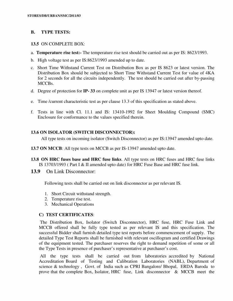
B. TYPE TESTS:
13.5 ON COMPLETE BOX:
a. Temperature rise test:- The temperature rise test should be carried out as per IS: 8623/1993.
b. High voltage test as per IS:8623/1993 amended up to date.
c. Short Time Withstand Current Test on Distribution Box as per IS 8623 or latest version. The
Distribution Box should be subjected to Short Time Withstand Current Test for value of 4KA
for 2 seconds for all the circuits independently. The test should be carried out after by-passing
MCCBs.
d. Degree of protection for IP- 33 on complete unit as per IS 13947 or latest version thereof.
e. Time /current characteristic test as per clause 13.3 of this specification as stated above.
f. Tests in line with Cl. 11.1 and IS: 13410-1992 for Sheet Moulding Compound (SMC)
Enclosure for conformance to the values specified therein.
13.6 ON ISOLATOR (SWITCH DISCONNECTOR):
All type tests on incoming isolator (Switch Disconnector) as per IS:13947 amended upto date.
13.7 ON MCCB: All type tests on MCCB as per IS-13947 amended upto date.
13.8 ON HRC fuses base and HRC fuse links. All type tests on HRC fuses and HRC fuse links
IS 13703/1993 ( Part I & II amended upto date) for HRC Fuse Base and HRC fuse link.
13.9 On Link Disconnector:
Following tests shall be carried out on link disconnector as per relevant IS.
1. Short Circuit withstand strength.
2. Temperature rise test.
3. Mechanical Operations
C) TEST CERTIFICATES:
The Distribution Box, Isolator (Switch Disconnector), HRC fuse, HRC Fuse Link and
MCCB offered shall be fully type tested as per relevant IS and this specification. The
successful Bidder shall furnish detailed type test reports before commencement of supply. The
detailed Type Test Reports shall be furnished with relevant oscillogram and certified Drawings
of the equipment tested. The purchaser reserves the right to demand repetition of some or all
the Type Tests in presence of purchaser’s representative at purchaser’s cost.
All the type tests shall be carried out from laboratories accredited by National
Accreditation Board of Testing and Calibration Laboratories (NABL), Department of
science & technology , Govt. of India such as CPRI Bangalore/ Bhopal, ERDA Baroda to
prove that the complete Box, Isolator, HRC fuse, Link disconnector & MCCB meet the
STORES/DB/URBAN/SMC/2011/03
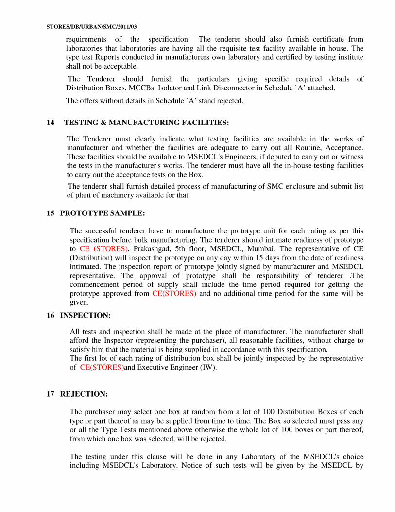
requirements of the specification. The tenderer should also furnish certificate from
laboratories that laboratories are having all the requisite test facility available in house. The
type test Reports conducted in manufacturers own laboratory and certified by testing institute
shall not be acceptable.
The Tenderer should furnish the particulars giving specific required details of
Distribution Boxes, MCCBs, Isolator and Link Disconnector in Schedule `A’ attached.
The offers without details in Schedule `A’ stand rejected.
14 TESTING & MANUFACTURING FACILITIES:
The Tenderer must clearly indicate what testing facilities are available in the works of
manufacturer and whether the facilities are adequate to carry out all Routine, Acceptance.
These facilities should be available to MSEDCL's Engineers, if deputed to carry out or witness
the tests in the manufacturer's works. The tenderer must have all the in-house testing facilities
to carry out the acceptance tests on the Box.
The tenderer shall furnish detailed process of manufacturing of SMC enclosure and submit list
of plant of machinery available for that.
15 PROTOTYPE SAMPLE:
The successful tenderer have to manufacture the prototype unit for each rating as per this
specification before bulk manufacturing. The tenderer should intimate readiness of prototype
to CE (STORES), Prakashgad, 5th floor, MSEDCL, Mumbai. The representative of CE
(Distribution) will inspect the prototype on any day within 15 days from the date of readiness
intimated. The inspection report of prototype jointly signed by manufacturer and MSEDCL
representative. The approval of prototype shall be responsibility of tenderer .The
commencement period of supply shall include the time period required for getting the
prototype approved from CE(STORES) and no additional time period for the same will be
given.
16 INSPECTION:
All tests and inspection shall be made at the place of manufacturer. The manufacturer shall
afford the Inspector (representing the purchaser), all reasonable facilities, without charge to
satisfy him that the material is being supplied in accordance with this specification.
The first lot of each rating of distribution box shall be jointly inspected by the representative
of CE(STORES)and Executive Engineer (IW).
17 REJECTION:
The purchaser may select one box at random from a lot of 100 Distribution Boxes of each
type or part thereof as may be supplied from time to time. The Box so selected must pass any
or all the Type Tests mentioned above otherwise the whole lot of 100 boxes or part thereof,
from which one box was selected, will be rejected.
The testing under this clause will be done in any Laboratory of the MSEDCL's choice
including MSEDCL's Laboratory. Notice of such tests will be given by the MSEDCL by
STORES/DB/URBAN/SMC/2011/03
ordinary post to supplier and the date of test may not be altered to the convenience or request
of the supplier. The supplier is at liberty to be present during the testing.
The MSEDCL may, at its option, inspect the distribution boxes supplied to the different
Stores at site or at departmental Stores. If any of the technical particulars are seen to be in
variance than the guaranteed technical particulars, the whole lot of boxes will be rejected.
18 SCHEDULES:
a. The tenderer shall fill in the following schedule, which form part of the tender
specification and offer. If the schedules are not submitted duly filled-in with the offer,
the offer shall be liable for rejection.
Schedule `A’ - Guaranteed Technical Particulars
Schedule `B' - Tenderer's Experience.
b. The tenderer shall submit the list of orders for similar type of equipments, executed or
under execution during the last three years, with full details in the schedule of
Tenderer's experience (Schedule `B') to enable purchaser. to evaluate the tender
19 DRAWINGS ENCLOSED: A list of indicative drawings of distribution box and its components is given below:
i. DIST/DB/02/B ii. DIST/DB/SMC/URBAN/2010/02
iii. DIST/DB/SMC/URBAN/2010/03 iv. Dist/DB/01/B
v. DIST/DB/SMC/URBAN/2010/05 vii.DIST/DB/SMC/URBAN/2010/06
viii. DIST/DB/SMC/URBAN/2010/07 ix. DIST/DB/SMC/URBAN/2010/08
xi. DIST/DB/SMC/URBAN/2010/09 x. DIST/DB/SMC/URBAN/2010/10
xii. DIST/DB/SMC/URBAN/2010/11 xiii. Annexure –I.
The successful bidder shall submit set of all above drawings of the distribution box and its
components in triplicate to CE (STORES) office and get approved before commencement of
supply (i.e. Ist Lot of Distribution Boxes).
STORES/DB/URBAN/SMC/2011/03
SCHEDULE - `A'
E-tendering Guaranteed Technical Particulars
STORES/DB/URBAN/SMC/2011/03
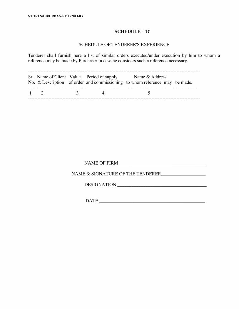
SCHEDULE - `B'
SCHEDULE OF TENDERER'S EXPERIENCE
Tenderer shall furnish here a list of similar orders executed/under execution by him to whom a
reference may be made by Purchaser in case he considers such a reference necessary.
--------------------------------------------------------------------------------------------------------------
Sr. Name of Client Value Period of supply Name & Address
No. & Description of order and commissioning to whom reference may be made.
--------------------------------------------------------------------------------------------------------------
1 2 3 4 5
--------------------------------------------------------------------------------------------------------------
NAME OF FIRM _____________________________________
NAME & SIGNATURE OF THE TENDERER___________________
DESIGNATION ______________________________________
DATE _____________________________________________
STORES/DB/URBAN/SMC/2011/03
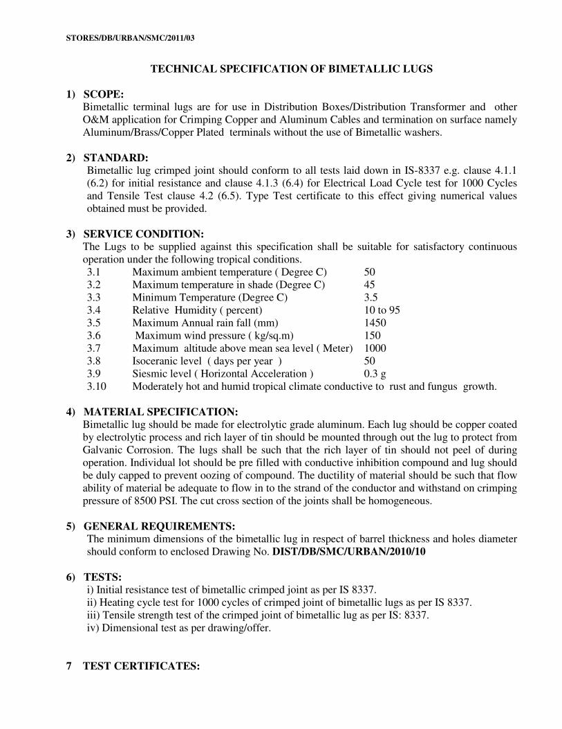
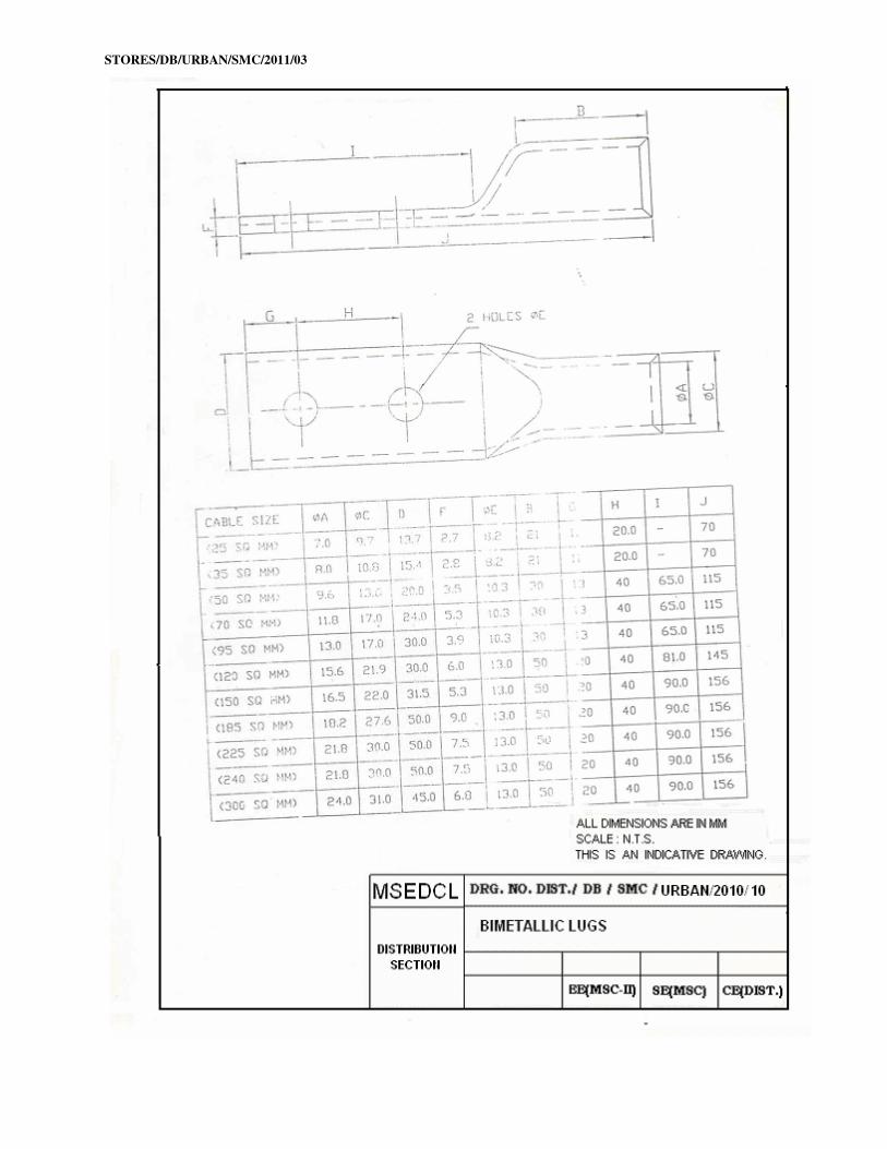
TECHNICAL SPECIFICATION OF BIMETALLIC LUGS
1) SCOPE: Bimetallic terminal lugs are for use in Distribution Boxes/Distribution Transformer and other
O&M application for Crimping Copper and Aluminum Cables and termination on surface namely
Aluminum/Brass/Copper Plated terminals without the use of Bimetallic washers.
2) STANDARD: Bimetallic lug crimped joint should conform to all tests laid down in IS-8337 e.g. clause 4.1.1
(6.2) for initial resistance and clause 4.1.3 (6.4) for Electrical Load Cycle test for 1000 Cycles
and Tensile Test clause 4.2 (6.5). Type Test certificate to this effect giving numerical values
obtained must be provided.
3) SERVICE CONDITION: The Lugs to be supplied against this specification shall be suitable for satisfactory continuous
operation under the following tropical conditions.
3.1 Maximum ambient temperature ( Degree C) 50
3.2 Maximum temperature in shade (Degree C) 45
3.3 Minimum Temperature (Degree C) 3.5
3.4 Relative Humidity ( percent) 10 to 95
3.5 Maximum Annual rain fall (mm) 1450
3.6 Maximum wind pressure ( kg/sq.m) 150
3.7 Maximum altitude above mean sea level ( Meter) 1000
3.8 Isoceranic level ( days per year ) 50
3.9 Siesmic level ( Horizontal Acceleration ) 0.3 g
3.10 Moderately hot and humid tropical climate conductive to rust and fungus growth.
4) MATERIAL SPECIFICATION: Bimetallic lug should be made for electrolytic grade aluminum. Each lug should be copper coated
by electrolytic process and rich layer of tin should be mounted through out the lug to protect from
Galvanic Corrosion. The lugs shall be such that the rich layer of tin should not peel of during
operation. Individual lot should be pre filled with conductive inhibition compound and lug should
be duly capped to prevent oozing of compound. The ductility of material should be such that flow
ability of material be adequate to flow in to the strand of the conductor and withstand on crimping
pressure of 8500 PSI. The cut cross section of the joints shall be homogeneous.
5) GENERAL REQUIREMENTS: The minimum dimensions of the bimetallic lug in respect of barrel thickness and holes diameter
should conform to enclosed Drawing No. DIST/DB/SMC/URBAN/2010/10
6) TESTS: i) Initial resistance test of bimetallic crimped joint as per IS 8337.
ii) Heating cycle test for 1000 cycles of crimped joint of bimetallic lugs as per IS 8337.
iii) Tensile strength test of the crimped joint of bimetallic lug as per IS: 8337.
iv) Dimensional test as per drawing/offer.
7 TEST CERTIFICATES:
STORES/DB/URBAN/SMC/2011/03
At present the following makes and types of bimetallic lugs are accepted by the MSEDCL.
Usha Martin Industries, Ismail, Chetna , Klippon, SRI, Alcon, NES , Hames and HB
In case any other equivalent make of bimetallic lugs, if bidder offer, they should indicate makes
and types of bimetallic lugs in E-tendering GTP. The bidders should submit complete test reports
of the bimetallic lugs as per this specification, clause No. 6 to CE (STORES) for approval before
commencement of supply. The Tests on lugs should be done in any reputed independent
laboratory.
8. DRAWING ENCLOSED: No. DIST/DB/SMC/URBAN/2010/10
STORES/DB/URBAN/SMC/2011/03
STORES/DB/URBAN/SMC/2011/03
STORES/DB/URBAN/SMC/2011/03
STORES/DB/URBAN/SMC/2011/03
STORES/DB/URBAN/SMC/2011/03
STORES/DB/URBAN/SMC/2011/03
STORES/DB/URBAN/SMC/2011/03
STORES/DB/URBAN/SMC/2011/03
STORES/DB/URBAN/SMC/2011/03
STORES/DB/URBAN/SMC/2011/03
STORES/DB/URBAN/SMC/2011/03
STORES/DB/URBAN/SMC/2011/03
STORES/DB/URBAN/SMC/2011/03
STORES/DB/URBAN/SMC/2011/03
STORES/DB/URBAN/SMC/2011/03
STORES/DB/URBAN/SMC/2011/03
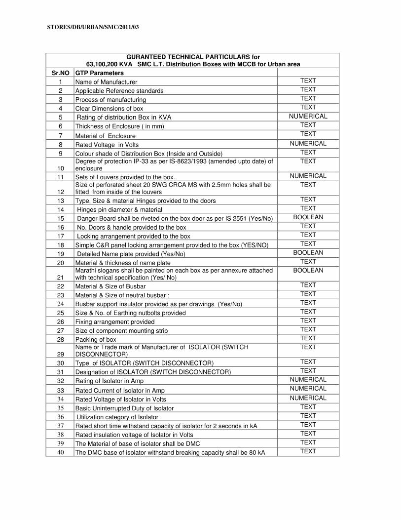
GURANTEED TECHNICAL PARTICULARS for
63,100,200 KVA SMC L.T. Distribution Boxes with MCCB for Urban area
Sr.NO GTP Parameters
1 Name of Manufacturer TEXT
2 Applicable Reference standards TEXT
3 Process of manufacturing TEXT
4 Clear Dimensions of box TEXT
5 Rating of distribution Box in KVA NUMERICAL
6 Thickness of Enclosure ( in mm) TEXT
7 Material of Enclosure TEXT
8 Rated Voltage in Volts NUMERICAL
9 Colour shade of Distribution Box (Inside and Outside) TEXT
10 Degree of protection IP-33 as per IS-8623/1993 (amended upto date) of enclosure
TEXT
11 Sets of Louvers provided to the box. NUMERICAL
12 Size of perforated sheet 20 SWG CRCA MS with 2.5mm holes shall be fitted from inside of the louvers
TEXT
13 Type, Size & material Hinges provided to the doors TEXT
14 Hinges pin diameter & material TEXT
15 Danger Board shall be riveted on the box door as per IS 2551 (Yes/No) BOOLEAN
16 No. Doors & handle provided to the box TEXT
17 Locking arrangement provided to the box TEXT
18 Simple C&R panel locking arrangement provided to the box (YES/NO) TEXT
19 Detailed Name plate provided (Yes/No) BOOLEAN
20 Material & thickness of name plate TEXT
21 Marathi slogans shall be painted on each box as per annexure attached with technical specification (Yes/ No)
BOOLEAN
22 Material & Size of Busbar TEXT
23 Material & Size of neutral busbar : TEXT
24 Busbar support insulator provided as per drawings (Yes/No) TEXT
25 Size & No. of Earthing nutbolts provided TEXT
26 Fixing arrangement provided TEXT
27 Size of component mounting strip TEXT
28 Packing of box TEXT
29 Name or Trade mark of Manufacturer of ISOLATOR (SWITCH DISCONNECTOR)
TEXT
30 Type of ISOLATOR (SWITCH DISCONNECTOR) TEXT
31 Designation of ISOLATOR (SWITCH DISCONNECTOR) TEXT
32 Rating of Isolator in Amp NUMERICAL
33 Rated Current of Isolator in Amp NUMERICAL
34 Rated Voltage of Isolator in Volts NUMERICAL
35 Basic Uninterrupted Duty of Isolator TEXT
36 Utilization category of Isolator TEXT
37 Rated short time withstand capacity of isolator for 2 seconds in kA TEXT
38 Rated insulation voltage of Isolator in Volts TEXT
39 The Material of base of isolator shall be DMC TEXT
40 The DMC base of isolator withstand breaking capacity shall be 80 kA TEXT
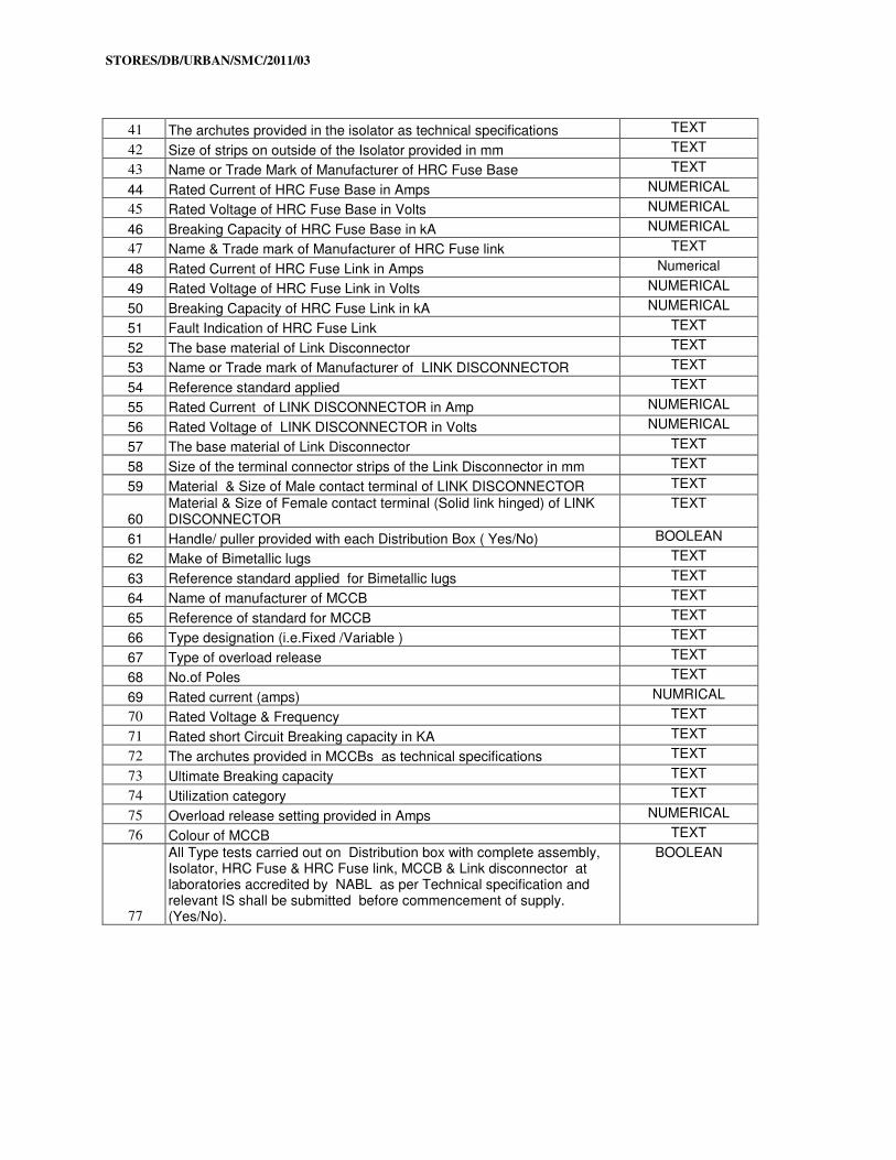
STORES/DB/URBAN/SMC/2011/03
41 The archutes provided in the isolator as technical specifications TEXT
42 Size of strips on outside of the Isolator provided in mm TEXT
43 Name or Trade Mark of Manufacturer of HRC Fuse Base TEXT
44 Rated Current of HRC Fuse Base in Amps NUMERICAL
45 Rated Voltage of HRC Fuse Base in Volts NUMERICAL
46 Breaking Capacity of HRC Fuse Base in kA NUMERICAL
47 Name & Trade mark of Manufacturer of HRC Fuse link TEXT
48 Rated Current of HRC Fuse Link in Amps Numerical
49 Rated Voltage of HRC Fuse Link in Volts NUMERICAL
50 Breaking Capacity of HRC Fuse Link in kA NUMERICAL
51 Fault Indication of HRC Fuse Link TEXT
52 The base material of Link Disconnector TEXT
53 Name or Trade mark of Manufacturer of LINK DISCONNECTOR TEXT
54 Reference standard applied TEXT
55 Rated Current of LINK DISCONNECTOR in Amp NUMERICAL
56 Rated Voltage of LINK DISCONNECTOR in Volts NUMERICAL
57 The base material of Link Disconnector TEXT
58 Size of the terminal connector strips of the Link Disconnector in mm TEXT
59 Material & Size of Male contact terminal of LINK DISCONNECTOR TEXT
60 Material & Size of Female contact terminal (Solid link hinged) of LINK DISCONNECTOR
TEXT
61 Handle/ puller provided with each Distribution Box ( Yes/No) BOOLEAN
62 Make of Bimetallic lugs TEXT
63 Reference standard applied for Bimetallic lugs TEXT
64 Name of manufacturer of MCCB TEXT
65 Reference of standard for MCCB TEXT
66 Type designation (i.e.Fixed /Variable ) TEXT
67 Type of overload release TEXT
68 No.of Poles TEXT
69 Rated current (amps) NUMRICAL
70 Rated Voltage & Frequency TEXT
71 Rated short Circuit Breaking capacity in KA TEXT
72 The archutes provided in MCCBs as technical specifications TEXT
73 Ultimate Breaking capacity TEXT
74 Utilization category TEXT
75 Overload release setting provided in Amps NUMERICAL
76 Colour of MCCB TEXT
77
All Type tests carried out on Distribution box with complete assembly, Isolator, HRC Fuse & HRC Fuse link, MCCB & Link disconnector at laboratories accredited by NABL as per Technical specification and relevant IS shall be submitted before commencement of supply. (Yes/No).
BOOLEAN