Embed Size (px)
Citation preview
WHITE PAPER
C37.94 - Installation & Maintenance 1. INTRODUCTION
Power utility companies constantly monitor high voltage power lines in order to ensure a secure and uninterrupted supply of electricity. Protection relays are used at substations and other critical locations controlled through communications links in order to isolate faults, protecting equipment and plant. The communications channels used for protection applications demand the highest level of availability with very low delays. Legacy Telecom networks historically have been interconnected using metallic circuits the problem being that the substation environment is characterised by high levels of electromagnetic fields, which can disturb transmissions on copper wires.
To avoid the problems electromagnetic fields can have on transmission circuits it is recommended to use optical links using the IEEE C37.94 standard. The IEEE C37.94 standard defines the rules to interconnect teleprotection and multiplexer devices from different manufacturers using optical fibres.
All rights reserved. No part of this document may be stored, copied or transmitted, by any means, without the permission in written of the Legal Owner
© 2014 ALBEDO Telecom
Figure 1 Protection of high voltage power lines is a fundamental task of power utility companies to deliver a secure and uninterrupted supply of electricity.
2 / 6
2. PROTECTION OF HIGH VOLTAGE PoWER LINES
Authorities use a teleprotection schema to enable substations to communicate with one another to selectively isolate faults on high voltage lines, transformers, reactors and other important elements of electrical plant. This requires the continuous exchange of data over the utilities telecommunication network in order to assure correct operation. It is imperative that the telecom network therefore should always be in perfect condition in terms of availability, performance, quality and delay.
Telecom networks in the past have used transmission circuits that were vulnerable to electromagnetic and radio interference (EMI/RFI), signal ground loops, and ground potential rise. Communications circuits vulnerable to interference and disturbance are not acceptable where the reliable transport of teleprotection protocols is required.
The electrical substation environment is usually characterised by a high level of electromagnetic fields caused by the high voltages and currents in power lines. Moreover, during times when high voltage fault conditions occur electromagnetic disturbances can rise significantly causing communication errors on copper based communication circuits. The reliability of the communications link interconnecting the protection relays is critical and must be resilient to the effects encountered in these high voltage areas such as high frequency induction and ground potential rise.
Substation 1 Substation 2
Multiplexer E1, PDH, SDH Protection Channels Voice, Data, Video
Figure 2 Teleprotection architecture using C37.94 in normal operation.
Multiplexer E1, PDH, SDH
Protection Channels Voice, Data, Video
High Voltage
Power Relay Power Relay
Fiber Optics IEEE C37.94
Fiber Optics IEEE C37.94
PDH SDH
3 / 6
To prevent these issues the electrical distribution industry moved to optical fibres to connect protection relays installed in substations. Fibre optic connections do not have a ground path and are therefore immune to the interferences caused by electrical noise. T h e u s e o f fully optical links from power relays to multiplexers using the IEEE C37.94 standard has become widespread in the industry.
Protection schemes using IEEE C37.94 interfaces can transport signals across fault tolerant networks of different kinds including PDH/SDH and Packet networks. These fault tolerant networks help increase the reliability and availability of communications circuits helping ensure critical teleprotection data interchanges.
3. THE IEEE C37.94 STANDARD
Teleprotection systems must isolate faults very quickly to preventing dam-‐ age to the network and power outages. The IEEE committee defined the C37.94 as a programmable n x 64 kbps (n=1...12) multimode optical fibre interface to provide transparent communications between teleprotection relays and multiplexers for distances of up to 2 km. Later on the industry a l s o adopted monomode optical fibre as well in order to reach longer distances.
The standard defines the protection and communications equipment inside a substation using optical fibres, the method for clock recovery, jitter tolerances allowed in the signals, physical connection method, and the actions the protection equipment must follow when any kind of network anomalies and faults occur. Many protection relay manufacturers including ABB, SEL, RFL, RAD and others have already implemented C37.94. Teleprotection equipment often offers a choice of WAN transmission interfaces including IEEE C37.94 compliant fibre interfaces, G.703, 64Kbps co-‐directional, E1 and increasingly Ethernet.
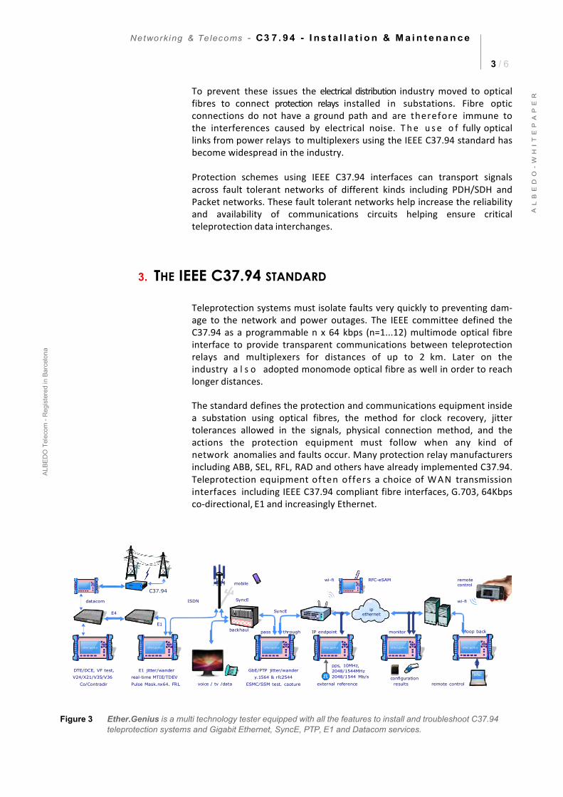
Figure 3 Ether.Genius is a multi technology tester equipped with all the features to install and troubleshoot C37.94 teleprotection systems and Gigabit Ethernet, SyncE, PTP, E1 and Datacom services.
C37.94
4 / 6
4. C37.94 Testing
Before C37.94 interfaces and circuits are handed over for protection purposes they should be tested and verified that they meet the required standards and requirements. There is a major difference between point-‐to-‐point C37.94 circuits and multiplexed channels running over SDH or Packet based transmission networks although both require testing to ensure correct operation.
Direct point-‐to-‐point C37.94 circuits perform very well and are easy to test because they are symmetrical, have a fixed latency and do not share bandwidth with other applications. On the other hand C37.94 interfaces that are multiplexed and transported over synchronous digital hierarchy (SONET/SDH) or packet networks are not symmetrical, have variable delays and also carry other data that can impact on the transmission of critical protection data.
Bit Error Rate (BER) Testing
A BER test verifies the ability to deliver error free data between two network ports. This test is widely deployed in communications networks as it can detect a number of issues occurring anywhere between two point on a network including:
• Noise interfering with the transmission medium and networkdevices.
• Failing or marginal components in active network devices.• Marginal electrical signals or power in lasers on fibre connections.• Framing errors due to issues with communications clocks causing
framing errors and lost data.• Interruptions due to network switching and other events.• Delays and loss of data due to network overloads or buffer
overflow in network and multiplexer devices.
A BER test can be run for a short period of time or over a number of hours in order to expose cyclical network events, such as changing bandwidth usage patterns in the utility’s network or random events like the switching of high-‐voltage lines. Depending on the transmission technology deployed longer periods of testing may be required if for example microwave or wireless links are used or when a packet based (Ethernet) transport network is being used.
Network Delay/Latency
Multiplexed and Packet networks normally suffer from some form of network delay and latency. Network delays can have serious implications on the performance of protection systems and it is vital to be able to test that any network delays are within the required specification.
Through the use of a loopback device it is possible to measure the round-‐trip delay between two ports on a network and by halving the delay
5 / 6
estimate the one-‐way delay. This assumes however that the transmission path between the two points is symmetrical, in reality when there are multiplexers and other network equipment in the path this is unlikely to be the case. The probability of asymmetrical network delays increases further when packet based (Ethernet) networks are used or when wireless, microwave or transport circuits are deployed.
With the use of the Global Positoning System (GPS) now being a viable option for portable and hand-‐held test equipment it is possible to measure the one-‐way-‐delay (OWD) between two network points. Performing a OWD test means that the delay/latency can be measured independently in each direction allowing for checks of network asymmetry.
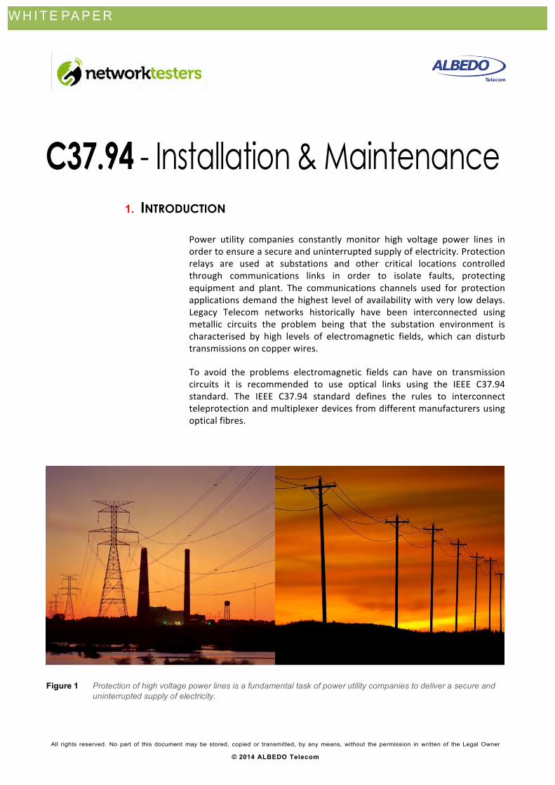
Substation 1 Substation 2
Multiplexer E1, PDH, SDH Protection Channels Voice, Data, Video
Multiplexer E1, PDH, SDH
Protection Channels Voice, Data, Video
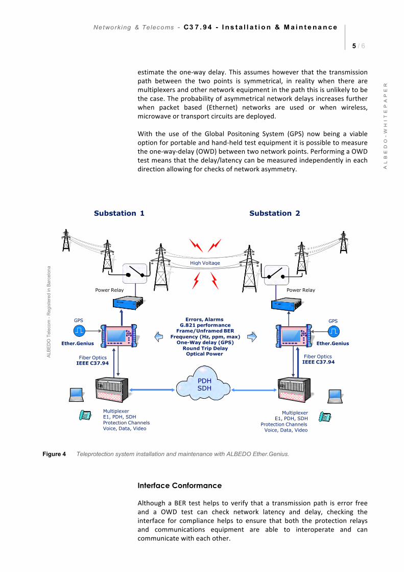
Figure 4 Teleprotection system installation and maintenance with ALBEDO Ether.Genius.
Interface Conformance
Although a BER test helps to verify that a transmission path is error free and a OWD test can check network latency and delay, checking the interface for compliance helps to ensure that both the protection relays and communications equipment are able to interoperate and can communicate with each other.
High Voltage
Power Relay Power Relay
Errors, Alarms G.821 performance
Frame/Unframed BERFrequency (Hz, ppm, max)
One-Way delay (GPS)Round Trip Delay
Optical Power Fiber Optics
IEEE C37.94 Fiber Optics
IEEE C37.94
SDH
6 / 6
These tests include basic communications checks such as clock frequency and deviation measurements, clock recovery and optical power measurement. Having the ability to carry out tests such as these in addition to BER and delay tests can help save considerable time when troubleshooting C.37.94 communication issues and problems.
5. ALBEDO ETHER.GENIUS AND C37.94
Ether.Genius provides a fully integrated test set to verify protection systems using C37.94 interfaces. A handheld multi technology tester, Ether.Genius can operate up to 24h hours on batteries and can verify networks and services based on Gigabit Ethernet (GbE), Synchronous Ethernet (SyncE), E1, Datacom, Precision Time Protocol (PTP, IEEE 1588v2), Jitter/Wander, One-‐way-‐delay using GPS, Round trip delay and Optical Power measurements.
Field engineers can use Ether.Genius to turn up new C37.94 deployments, or to troubleshoot and perform maintenance tests on teleprotection relays and multiplexers. Ether.Genius can perform bit error rate testing (BERT), events monitoring, one-‐way-‐delay measurements using GPS, round trip delays and optical power measurements.
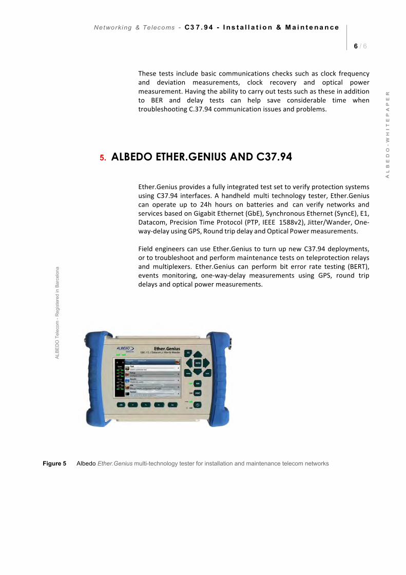
Figure 5 Albedo Ether.Genius multi-technology tester for installation and maintenance telecom networks
7 / 6
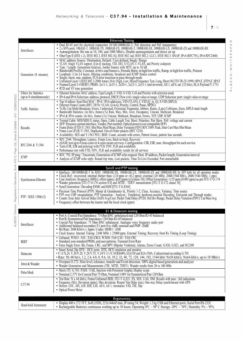
Ethernet Testing
Interfaces • Dual RJ-45 port for electrical connection 10/100/1000BASE-T; PoE detection and PoE transparency• 2 x SFPs ports: 10BASE-T, 100BASE-TX, 100BASE-FX, 1000BASE-T, 1000BASE-SX, 1000BASE-LX, 1000BASE-ZX and 1000BASE-BX• Autonegotiation: Bit rate at 10, 100, and 1000 Mbit/s, Disable autonegotiation and direct set up• EtherType II (DIX v.2), IEEE 802.3, IEEE 802.1Q, IEEE 802.1ad; IEEE 802.2–LLC1, IEEE 802.3–SNAP; IPv4 (RFC791), IPv6 RFC2460)
Generation (8 streams)
• MAC address: Source / Destination, Default / User defined, Single / Range• VLAN: Single VLAN support, Q-in-Q stacking, VID, DEI, S-VLAN, C-VLAN, and Priority codepoint• Type / Length: Generation/Analysis, Jumbo frames with MTU up to 10 kB• Bandwidth Profile: Constant, in bit/s and frames/s, Periodic Burst, in high/low traffic, Ramp, in high/low traffic, Poisson• Loopback: L1to L4 layers, filtering conditions, broadcast and ICMP frames control• Single, burst, rate, random, FCS error insertion in pass-through mode• Unframed Layer 1 (IEEE 802.3-2008 Annex 36A): High, Low, Mixed Frequency Test, Long, Short (NCITS TR-25-1999): RPAT, JJTPAT, SPAT• Framed Layer 2-4 BERT; PRBS: 2e11-1, 2e15-1, 2e20-1, 2e23-1, 2e31-1 and inverted, All 1, all 0, ud. (32 bits), SLA Payload Y.1731• RTD and VF tone generation
Filters for Statistics (up to 8 simultaneously)
• Ethernet Selection: MAC address, Type/Length, C-VID, S-VID, CoS and Priority with selection mask• IPv4 and IPv6 Selection: address, protocol, DSCP, Flow (v6): single value or range. UDP Selection: port: single value or range
Traffic Statistics
• Top 16 talkers: Sour/Dest MAC / IPv4 / IPv6 addresses, VID (VLAN), C-VID (Q_in_Q), S-VID (MPLS)• Ethernet Frame Counts (RFC 2819): VLAN, Q-in-Q, Priority, Control, Pause, BPDUs• Tx/Rx Uni-Multi-Broadcast, Errors, Undersized, Oversized, Fragments, Jabbers, Runts, (Late) Collisions, Sizes, MPLS stack length• Bandwidth Statistics: (in bit/s, frame/s,%) Rate, Max, Min, Aver, Occupancy, Unicast, Multicast, Broadcast• IPv4 & IPv6 counts: (in bit/s, frame/s,%) Unicast, Multicast, Broadcast, Errors, TCP, UDP, ICMP
Results
• Twisted Cable: MDI/MDI-X status, Open, Cable Length Test, Short, Polarities, Pair Skew. PoE: voltage and current• SFP: Presence current interface, Vendor, Part number, Optical power (over compatible SFP)• Frame Delay (FTD) Y.1563: Min/Max/Med/Mean; Delay Variation (FDV) RFC1889: Peak; Jitter Curr/Max/Min/Mean• Frame Loss (FLR) Y.1563, Duplicated: Out-of-Order packets (RFC 5236)• Availability: SES and Y.1563 PEU; BER: Count, seconds with errors, Pattern losses, pattern loss seconds
RFC-2544 & Y.1564 • RFC 2544: Throughput, Latency, Frame Loss, Back-to-back, Recovery• eSAM: test up to 8 non-color or 4 color aware services. Configuration: CIR, EIR, max. throughput for each service• Tests (CIR, EIR and policing) with FTD, FDV, FLR and availability• Performance test with FTD, FDV, FLR and availability results for all services
ICMP • RFC 792: IP ping / Traceroute, Generation of ICMP echo request: Dest. IP address, Packet length, Generation interval• Analysis of ICMP echo reply: Round trip time, Lost packets, Time-To-Live Exceeded, Port unreachable
Ergonomics
Hand-held Instrument • Display 480 x 272 TFT, Soft LEDS, 223x144x65 mm, IP rating 54; Weight: 1.2 kg USB and Ethernet ports, Serial Port RS-232C• Rechargeable Batteries continuous working up to 10 hours; Operating 0ºC ~ 50º C Storage -20ºC ~ 70ºC; Humidity 5% ~ 95%
SyncE and PTP testing
E1 & Datacom testing
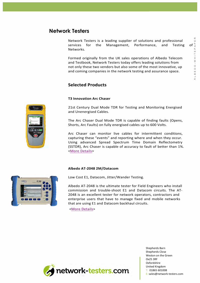
Network Testers Network Testers is a leading supplier of solutions and professional services for the Management, Performance, and Testing of Networks.
Formed originally from the UK sales operations of Albedo Telecom and Testbook, Network Testers today offers leading solutions from not only these two vendors but also some of the most innovative, up and coming companies in the network testing and assurance space.
Selected Products
T3 Innovation Arc Chaser
21st Century Dual Mode TDR for Testing and Monitoring Energised and Unenergised Cables.
The Arc Chaser Dual Mode TDR is capable of finding faults (Opens, Shorts, Arc Faults) on fully energised cables up to 600 Volts.
Arc Chaser can monitor live cables for intermittent conditions, capturing these “events” and reporting where and when they occur. Using advanced Spread Spectrum Time Domain Reflectometry (SSTDR), Arc Chaser is capable of accuracy to fault of better than 1%. <More Details>
Albedo AT-‐2048 2M/Datacom
Low Cost E1, Datacom, Jitter/Wander Testing.
Albedo AT-‐2048 is the ultimate tester for Field Engineers who install commission and trouble-‐shoot E1 and Datacom circuits. The AT-‐2048 is an excellent tester for network operators, contractors and enterprise users that have to manage fixed and mobile networks that are using E1 and Datacom backhaul circuits. <More Details>
Shepherds Barn Shepherds Close Weston on the Green Ox25 3RF Oxfordshire United Kingdom T: 01865 601008 E: sales@network-‐testers.com

![HIGH VOLTAGE Breakdown phenomenafaraday.ee.emu.edu.tr/eeng451/HIGHVOLTAGE - L12 - breakdown_To… · Breakdown voltage by streamer theory d: electrode gap [cm] (electrode seperation)](https://img.pdfslide.net/doc/110x75/5f077b6b7e708231d41d3322/high-voltage-breakdown-l12-breakdownto-breakdown-voltage-by-streamer-theory.jpg)