Embed Size (px)
DESCRIPTION
Project of hydraulic system
Citation preview

qwertyuiopasdfghjklzxcvbnmqwerty
uiopasdfghjklzxcvbnmqwertyuiopasd
fghjklzxcvbnmqwertyuiopasdfghjklzx
cvbnmqwertyuiopasdfghjklzxcvbnmq
wertyuiopasdfghjklzxcvbnmqwertyui
opasdfghjklzxcvbnmqwertyuiopasdfg
hjklzxcvbnmqwertyuiopasdfghjklzxc
vbnmqwertyuiopasdfghjklzxcvbnmq
wertyuiopasdfghjklzxcvbnmqwertyui
opasdfghjklzxcvbnmqwertyuiopasdfg
hjklzxcvbnmqwertyuiopasdfghjklzxc
vbnmqwertyuiopasdfghjklzxcvbnmq
wertyuiopasdfghjklzxcvbnmqwertyui
opasdfghjklzxcvbnmqwertyuiopasdfg
hjklzxcvbnmrtyuiopasdfghjklzxcvbn
mqwertyuiopasdfghjklzxcvbnmqwert
yuiopasdfghjklzxcvbnmqwertyuiopas
dfghjklzxcvbnmqwertyuiopasdfghjklz
3-WAY DROPPING DUMPER
www.BEProjectReport.com
VISIT US, CHOOSE THE PROJECT YOU LIKE AND CLICK THE DOWNLOAD BUTTON
3-WAY DROPPING DUMPER
www.BEProjectReport.com Page 2
CHAPTER 1
INTRODUCTION
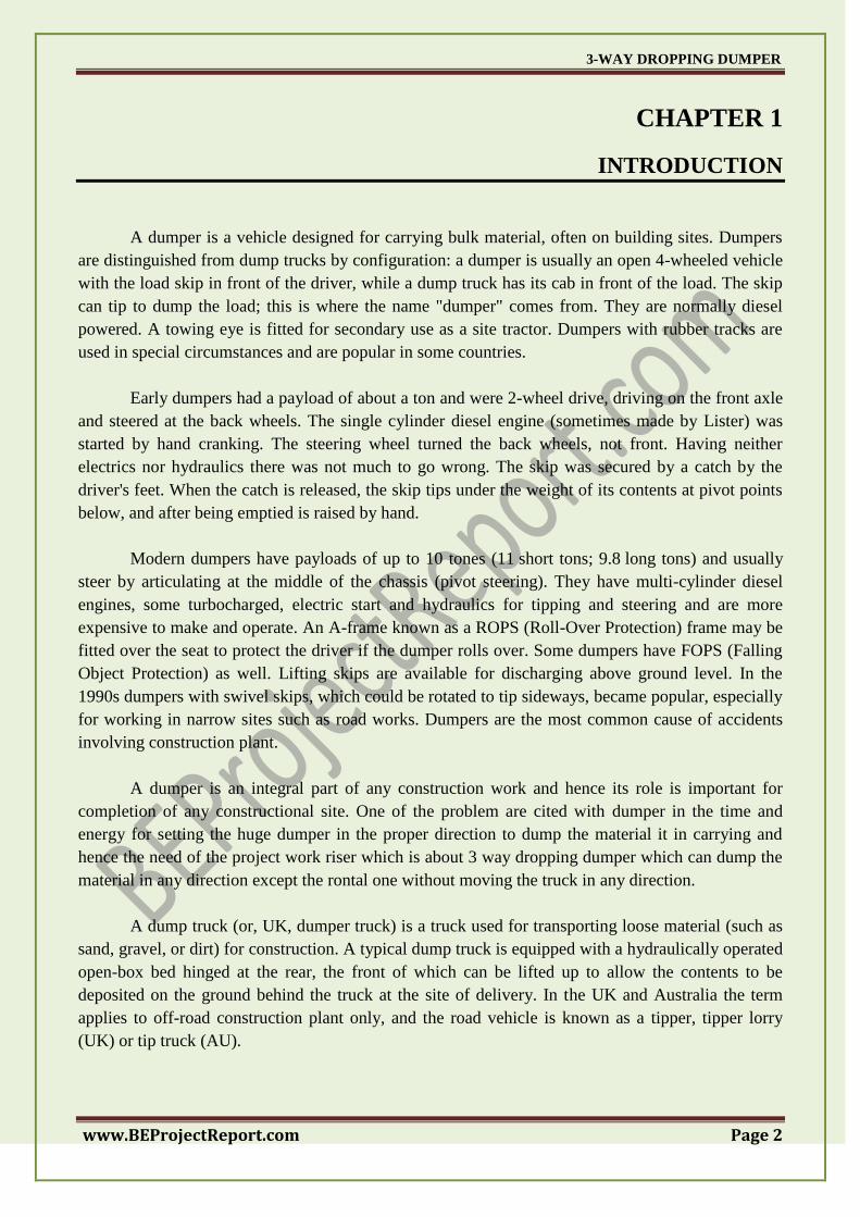
A dumper is a vehicle designed for carrying bulk material, often on building sites. Dumpers
are distinguished from dump trucks by configuration: a dumper is usually an open 4-wheeled vehicle
with the load skip in front of the driver, while a dump truck has its cab in front of the load. The skip
can tip to dump the load; this is where the name "dumper" comes from. They are normally diesel
powered. A towing eye is fitted for secondary use as a site tractor. Dumpers with rubber tracks are
used in special circumstances and are popular in some countries.
Early dumpers had a payload of about a ton and were 2-wheel drive, driving on the front axle
and steered at the back wheels. The single cylinder diesel engine (sometimes made by Lister) was
started by hand cranking. The steering wheel turned the back wheels, not front. Having neither
electrics nor hydraulics there was not much to go wrong. The skip was secured by a catch by the
driver's feet. When the catch is released, the skip tips under the weight of its contents at pivot points
below, and after being emptied is raised by hand.
Modern dumpers have payloads of up to 10 tones (11 short tons; 9.8 long tons) and usually
steer by articulating at the middle of the chassis (pivot steering). They have multi-cylinder diesel
engines, some turbocharged, electric start and hydraulics for tipping and steering and are more
expensive to make and operate. An A-frame known as a ROPS (Roll-Over Protection) frame may be
fitted over the seat to protect the driver if the dumper rolls over. Some dumpers have FOPS (Falling
Object Protection) as well. Lifting skips are available for discharging above ground level. In the
1990s dumpers with swivel skips, which could be rotated to tip sideways, became popular, especially
for working in narrow sites such as road works. Dumpers are the most common cause of accidents
involving construction plant.
A dumper is an integral part of any construction work and hence its role is important for
completion of any constructional site. One of the problem are cited with dumper in the time and
energy for setting the huge dumper in the proper direction to dump the material it in carrying and
hence the need of the project work riser which is about 3 way dropping dumper which can dump the
material in any direction except the rontal one without moving the truck in any direction.
A dump truck (or, UK, dumper truck) is a truck used for transporting loose material (such as
sand, gravel, or dirt) for construction. A typical dump truck is equipped with a hydraulically operated
open-box bed hinged at the rear, the front of which can be lifted up to allow the contents to be
deposited on the ground behind the truck at the site of delivery. In the UK and Australia the term
applies to off-road construction plant only, and the road vehicle is known as a tipper, tipper lorry
(UK) or tip truck (AU).
3-WAY DROPPING DUMPER
www.BEProjectReport.com Page 3
CHAPTER 2
HISTORY
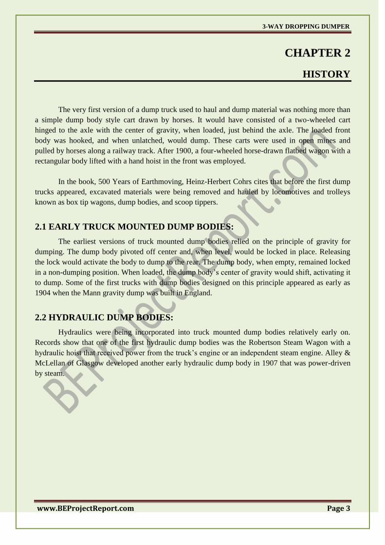
The very first version of a dump truck used to haul and dump material was nothing more than
a simple dump body style cart drawn by horses. It would have consisted of a two-wheeled cart
hinged to the axle with the center of gravity, when loaded, just behind the axle. The loaded front
body was hooked, and when unlatched, would dump. These carts were used in open mines and
pulled by horses along a railway track. After 1900, a four-wheeled horse-drawn flatbed wagon with a
rectangular body lifted with a hand hoist in the front was employed.
In the book, 500 Years of Earthmoving, Heinz-Herbert Cohrs cites that before the first dump
trucks appeared, excavated materials were being removed and hauled by locomotives and trolleys
known as box tip wagons, dump bodies, and scoop tippers.
2.1 EARLY TRUCK MOUNTED DUMP BODIES:
The earliest versions of truck mounted dump bodies relied on the principle of gravity for
dumping. The dump body pivoted off center and, when level, would be locked in place. Releasing
the lock would activate the body to dump to the rear. The dump body, when empty, remained locked
in a non-dumping position. When loaded, the dump body‘s center of gravity would shift, activating it
to dump. Some of the first trucks with dump bodies designed on this principle appeared as early as
1904 when the Mann gravity dump was built in England.
2.2 HYDRAULIC DUMP BODIES:
Hydraulics were being incorporated into truck mounted dump bodies relatively early on.
Records show that one of the first hydraulic dump bodies was the Robertson Steam Wagon with a
hydraulic hoist that received power from the truck‘s engine or an independent steam engine. Alley &
McLellan of Glasgow developed another early hydraulic dump body in 1907 that was power-driven
by steam.

3-WAY DROPPING DUMPER
www.BEProjectReport.com Page 4
Fig.2.1 2000 Sterling Lt9522 T/A Dump Truck
Some of the first truck mounted dump bodies that resembled today‘s bottom dump trucks
were being used in the 1920s onward to move coal. The ability of dump trucks to deliver rapid
unloading capabilities so more trips could be achieved in a shorter time frame was in great demand.
This resulted in the development of a type of dump body called a hopper, similar to a hopper railcar.
The dump body was elevated with struts and beams located on the underside in a scissor like
pattern. Pulling the beams close together automatically elevated the dump body. Elevating the dump
body allowed the free flow of material by gravity along chutes and for some distance from the truck.
Four screws in each corner that were powered by the truck‘s power take-off could also elevate the
dump body.
Gravity pitch would be designed into the body so that coal would feed out from the hopper
into the chute. A gate at the bottom of the chute controlled the outpouring of coal.
2.3 CRAWLER TRACTOR-TRAILER:
In the middle of the 1920s, crawler tractors pulling heavy dump trailers mounted on wheels
or tracks were becoming increasingly popular. Sometimes crawlers would pull two to five attached
trailers. Companies began developing wagons specifically designed for attachment to crawler
tractors. The first versions were mounted on tracks; however, when speed restrictions posed a
problem, the wagons were mounted on wheels to improve speed. Manufacturers of such trailers and
haulers included Euclid, James Hagy, LaPlant-Choate, Rex-Watson, and Streich and Western.
3-WAY DROPPING DUMPER
www.BEProjectReport.com Page 5
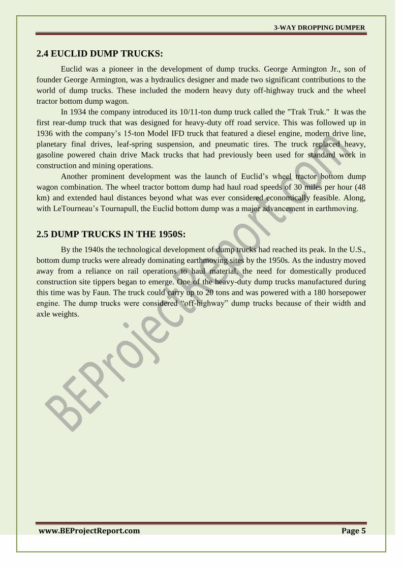
2.4 EUCLID DUMP TRUCKS:
Euclid was a pioneer in the development of dump trucks. George Armington Jr., son of
founder George Armington, was a hydraulics designer and made two significant contributions to the
world of dump trucks. These included the modern heavy duty off-highway truck and the wheel
tractor bottom dump wagon.
In 1934 the company introduced its 10/11-ton dump truck called the "Trak Truk." It was the
first rear-dump truck that was designed for heavy-duty off road service. This was followed up in
1936 with the company‘s 15-ton Model IFD truck that featured a diesel engine, modern drive line,
planetary final drives, leaf-spring suspension, and pneumatic tires. The truck replaced heavy,
gasoline powered chain drive Mack trucks that had previously been used for standard work in
construction and mining operations.
Another prominent development was the launch of Euclid‘s wheel tractor bottom dump
wagon combination. The wheel tractor bottom dump had haul road speeds of 30 miles per hour (48
km) and extended haul distances beyond what was ever considered economically feasible. Along,
with LeTourneau‘s Tournapull, the Euclid bottom dump was a major advancement in earthmoving.
2.5 DUMP TRUCKS IN THE 1950S:
By the 1940s the technological development of dump trucks had reached its peak. In the U.S.,
bottom dump trucks were already dominating earthmoving sites by the 1950s. As the industry moved
away from a reliance on rail operations to haul material, the need for domestically produced
construction site tippers began to emerge. One of the heavy-duty dump trucks manufactured during
this time was by Faun. The truck could carry up to 20 tons and was powered with a 180 horsepower
engine. The dump trucks were considered ―off-highway‖ dump trucks because of their width and
axle weights.
3-WAY DROPPING DUMPER
www.BEProjectReport.com Page 6
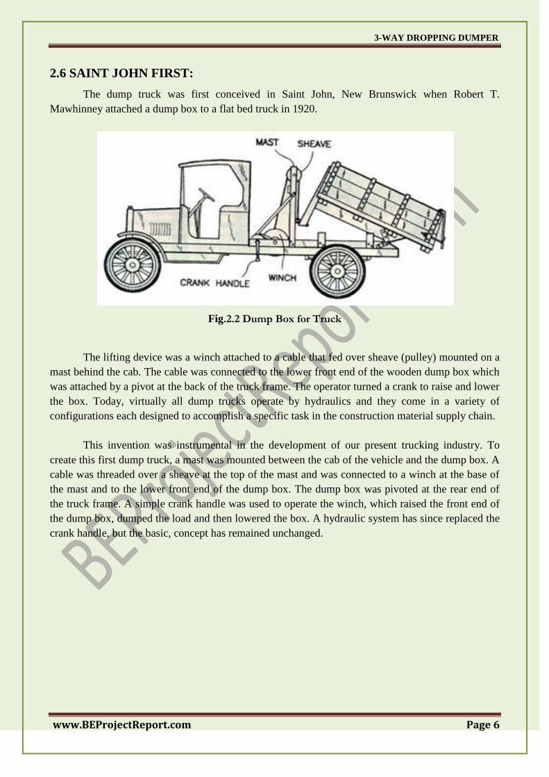
2.6 SAINT JOHN FIRST:
The dump truck was first conceived in Saint John, New Brunswick when Robert T.
Mawhinney attached a dump box to a flat bed truck in 1920.
Fig.2.2 Dump Box for Truck
The lifting device was a winch attached to a cable that fed over sheave (pulley) mounted on a
mast behind the cab. The cable was connected to the lower front end of the wooden dump box which
was attached by a pivot at the back of the truck frame. The operator turned a crank to raise and lower
the box. Today, virtually all dump trucks operate by hydraulics and they come in a variety of
configurations each designed to accomplish a specific task in the construction material supply chain.
This invention was instrumental in the development of our present trucking industry. To
create this first dump truck, a mast was mounted between the cab of the vehicle and the dump box. A
cable was threaded over a sheave at the top of the mast and was connected to a winch at the base of
the mast and to the lower front end of the dump box. The dump box was pivoted at the rear end of
the truck frame. A simple crank handle was used to operate the winch, which raised the front end of
the dump box, dumped the load and then lowered the box. A hydraulic system has since replaced the
crank handle, but the basic, concept has remained unchanged.
3-WAY DROPPING DUMPER
www.BEProjectReport.com Page 7
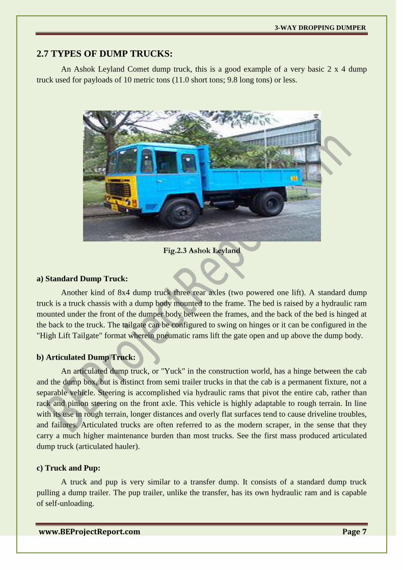
2.7 TYPES OF DUMP TRUCKS:
An Ashok Leyland Comet dump truck, this is a good example of a very basic 2 x 4 dump
truck used for payloads of 10 metric tons (11.0 short tons; 9.8 long tons) or less.
Fig.2.3 Ashok Leyland
a) Standard Dump Truck:
Another kind of 8x4 dump truck three rear axles (two powered one lift). A standard dump
truck is a truck chassis with a dump body mounted to the frame. The bed is raised by a hydraulic ram
mounted under the front of the dumper body between the frames, and the back of the bed is hinged at
the back to the truck. The tailgate can be configured to swing on hinges or it can be configured in the
"High Lift Tailgate" format wherein pneumatic rams lift the gate open and up above the dump body.
b) Articulated Dump Truck:
An articulated dump truck, or "Yuck" in the construction world, has a hinge between the cab
and the dump box, but is distinct from semi trailer trucks in that the cab is a permanent fixture, not a
separable vehicle. Steering is accomplished via hydraulic rams that pivot the entire cab, rather than
rack and pinion steering on the front axle. This vehicle is highly adaptable to rough terrain. In line
with its use in rough terrain, longer distances and overly flat surfaces tend to cause driveline troubles,
and failures. Articulated trucks are often referred to as the modern scraper, in the sense that they
carry a much higher maintenance burden than most trucks. See the first mass produced articulated
dump truck (articulated hauler).
c) Truck and Pup:
A truck and pup is very similar to a transfer dump. It consists of a standard dump truck
pulling a dump trailer. The pup trailer, unlike the transfer, has its own hydraulic ram and is capable
of self-unloading.
3-WAY DROPPING DUMPER
www.BEProjectReport.com Page 8
d) Super Dump Truck:
A Super dump is a straight dump truck equipped with a trailing axle, a lift able, load-bearing
axle rated as high as 13,000 pounds (5,897 kg). Trailing 11 to 13 feet (3.35 to 3.96 m) behind the
rear tandem, the trailing axle stretches the outer "bridge" measurement—the distance between the
first and last axles—to the maximum overall length allowed. This increases the gross weight allowed
under the federal bridge formula, which sets standards for truck size and weight. Depending on the
vehicle length and axle configuration, Super dumps can be rated as high as 80,000 pounds (36,287
kg). GVW and carry 26 short tons (23.6 t; 23.2 long tons) of payload or more. When the truck is
empty or ready to offload, the trailing axle toggles up off the road surface on two hydraulic arms to
clear the rear of the vehicle. Truck owners call their trailing axle-equipped trucks Super dumps
because they far exceed the payload, productivity, and return on investment of a conventional dump
truck. The Super dump and trailing axle concept was developed by Strong Industries of Houston,
Texas.
e) Semi Trailer End Dump Truck:
A semi end dump is a tractor-trailer combination wherein the trailer itself contains the
hydraulic hoist. A typical semi end dump has a 3-axle tractor pulling a 2-axle semi-trailer. The key
advantage of a semi end dump is rapid unloading. A key disadvantage is that they are very unstable
when raised in the dumping position limiting their use in many applications where the dumping
location is uneven or off level.
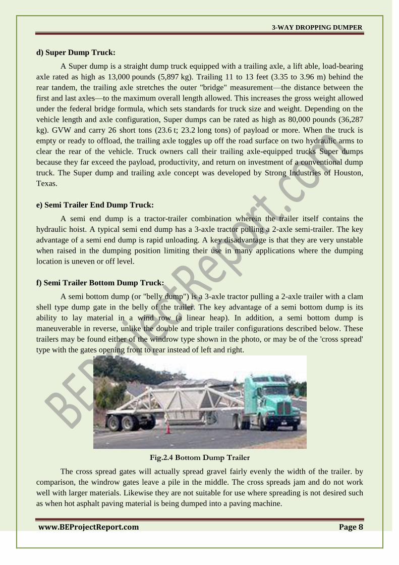
f) Semi Trailer Bottom Dump Truck:
A semi bottom dump (or "belly dump") is a 3-axle tractor pulling a 2-axle trailer with a clam
shell type dump gate in the belly of the trailer. The key advantage of a semi bottom dump is its
ability to lay material in a wind row (a linear heap). In addition, a semi bottom dump is
maneuverable in reverse, unlike the double and triple trailer configurations described below. These
trailers may be found either of the windrow type shown in the photo, or may be of the 'cross spread'
type with the gates opening front to rear instead of left and right.
Fig.2.4 Bottom Dump Trailer
The cross spread gates will actually spread gravel fairly evenly the width of the trailer. by
comparison, the windrow gates leave a pile in the middle. The cross spreads jam and do not work
well with larger materials. Likewise they are not suitable for use where spreading is not desired such
as when hot asphalt paving material is being dumped into a paving machine.
3-WAY DROPPING DUMPER
www.BEProjectReport.com Page 9
CHAPTER 3
EXPERIMENTAL PROCEDURE
The project being complicated was decide to be developed on a small scale model that should
be constructed using light weight material and should be hydraulically operated using plastic piston
and cylinder arrangement. Also this hydraulic piston and cylinder arrangement was decided to be
motor driven to make the same automatic. These motor run using a battery and are controlled using a
remote control that is attached with the base model using wires / FRC cable and these after
controlled by operator.
A conventional dump truck is mounted on a truck chassis and has an open dump box
hydraulically operated and hinged at the rear of the truck usually by one or more hydraulic rams that
raise the dump box to unload contents at a delivery site. These hydraulic rams are either front loaded
or mounted in the underbody and are driven from a gear box power take-off. Hydraulic rams
mounted in the underbody provide the capability of the dump body to tip the dump box on a three-
way basis, either to the left or right side or to the rear.
3.1 HOW A TYPICAL TIPPER TRUCKS WORKS?
The tipping mechanism is the heart of a three way tipper construction truck. Tipping
mechanisms work basically on the following:
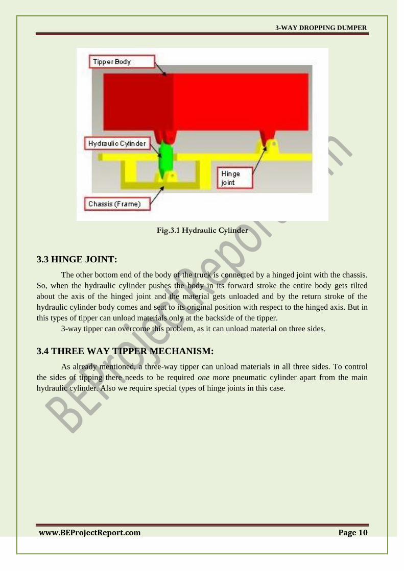
3.2 HYDRAULIC CYLINDER:
A hydraulic cylinder is placed below the body of truck longitudinally at one end of the truck,
and the piston end of the hydraulic cylinder is connected by the means of a pivot joint to the chassis
of truck.
In the forward stroke of the cylinder, it pushes the truck body upward thus gives necessary
lift for tipping dumping. So, in the forward stroke of the cylinder, the truck is unloaded. In the return
stroke of the cylinder the body of the truck comes to its original position.
3-WAY DROPPING DUMPER
www.BEProjectReport.com Page 10
Fig.3.1 Hydraulic Cylinder
3.3 HINGE JOINT:
The other bottom end of the body of the truck is connected by a hinged joint with the chassis.
So, when the hydraulic cylinder pushes the body in its forward stroke the entire body gets tilted
about the axis of the hinged joint and the material gets unloaded and by the return stroke of the
hydraulic cylinder body comes and seat to its original position with respect to the hinged axis. But in
this types of tipper can unload materials only at the backside of the tipper.
3-way tipper can overcome this problem, as it can unload material on three sides.
3.4 THREE WAY TIPPER MECHANISM:
As already mentioned, a three-way tipper can unload materials in all three sides. To control
the sides of tipping there needs to be required one more pneumatic cylinder apart from the main
hydraulic cylinder. Also we require special types of hinge joints in this case.
3-WAY DROPPING DUMPER
www.BEProjectReport.com Page 11
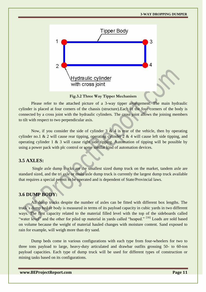
Fig.3.2 Three Way Tipper Mechanism
Please refer to the attached picture of a 3-way tipper arrangement. The main hydraulic
cylinder is placed at four corners of the chassis (structure).Each of the four corners of the body is
connected by a cross joint with the hydraulic cylinders. The cross joint allows the joining members
to tilt with respect to two perpendicular axis.
Now, if you consider the side of cylinder 3 & 4 is rear of the vehicle, then by operating
cylinder no.1 & 2 will cause rear tipping, operating cylinder 2 & 4 will cause left side tipping, and
operating cylinder 1 & 3 will cause right side tipping. Automation of tipping will be possible by
using a power pack with plc control or some similar kind of automation devices.
3.5 AXLES:
Single axle dump trucks are the smallest sized dump truck on the market, tandem axle are
standard sized, and the tri axle or multi axle dump truck is currently the largest dump truck available
that requires a special permit to be operated and is dependent of State/Provincial laws.
3.6 DUMP BODY:
All dump trucks despite the number of axles can be fitted with different box lengths. The
truck‘s dump bed or body is measured in terms of its payload capacity in cubic yards in two different
ways. The first capacity related to the material filled level with the top of the sideboards called
―water level‖ and the other for piled up material in yards called ―heaped.‖ [16]
Loads are sold based
on volume because the weight of material hauled changes with moisture content. Sand exposed to
rain for example, will weigh more than dry sand.
Dump beds come in various configurations with each type from four-wheelers for two to
three tons payload to large, heavy-duty articulated and drawbar outfits grossing 50- to 60-ton
payload capacities. Each type of dump truck will be used for different types of construction or
mining tasks based on its configurations.
3-WAY DROPPING DUMPER
www.BEProjectReport.com Page 12
3.7 DUMP TRUCK OPERATIONS:
During dumping operations, the truck should be on level ground or inclined uphill with the
front of the truck facing downward. When the truck is in position, release the lower latches of the
tailgate with the hand lever at the front left corner of the body. Then engage the control for the dump
truck body. Hydraulic pressure will begin to hoist the dump truck body, and as the body rises, the
load will slide backward under the open tailgate. If the load piles up and blocks the tailgate), place
the truck in low gear and move it forward until there is more space to dump the remainder of the
load.
If the load does not slide out easily, have someone dislodge it with a long-handled shovel,
taking care not to stand in the immediate dumping area. When dumping a load of rocks or other large
solids, see that the tailgate is latched at the bottom, but unfastened at the top, so that the tailgate can
drop down and the load can drop. Not all dump trucks have tailgate wings. On those that do not, you
have to drop the tailgate down and support it with chains. To spread a load over a large area, shift the
truck into low gear and drive it slowly forward while dumping.
The dump truck body can be held in any position by returning the control lever to the hold
position. When dumping is completed, lower the body by returning the control lever to the lowering
position. Then close the tailgate latches.
The load in a dump truck should be distributed evenly. Heaped loads to the front put more
strain on the hoist. Loads to one side can damage the hinge pins, the dump bed, or bend the truck
chassis. Remember: If your load should be distributed unevenly and dumped on uneven ground, you
could find yourself in great difficulty.
3.8 HYDRAULIC SYSTEM:
The basic idea behind any hydraulic system is very simple. Force that is applied at one point
is transmitted to another point using an incompressible fluid. The fluid is almost always an oil of
some sort. The force is almost always multiplied in the process. The picture below shows the
simplest possible hydraulic system.
In this drawing, two pistons (red) fit into two glass cylinders filled with oil (light blue) and
connected to one another with an oil-filled pipe. If you apply a downward force to one piston (the
left one in this drawing), then the force is transmitted to the second piston through the oil in the pipe.
Since oil is incompressible, the efficiency is very good -- almost all of the applied force appears at
the second piston. The great thing about hydraulic systems is that the pipe connecting the two
cylinders can be any length and shape, allowing it to snake through all sorts of things separating the
two pistons. The pipe can also fork, so that one master cylinder can drive more than one slave
cylinder if desired.
The neat thing about hydraulic systems is that it is very easy to add force multiplication (or
division) to the system. If you have read How a Block and Tackle Works or How Gears Work, then
3-WAY DROPPING DUMPER
www.BEProjectReport.com Page 13
you know that trading force for distance is very common in mechanical systems. In a hydraulic
system, all you do is change the size of one piston and cylinder relative to the other.
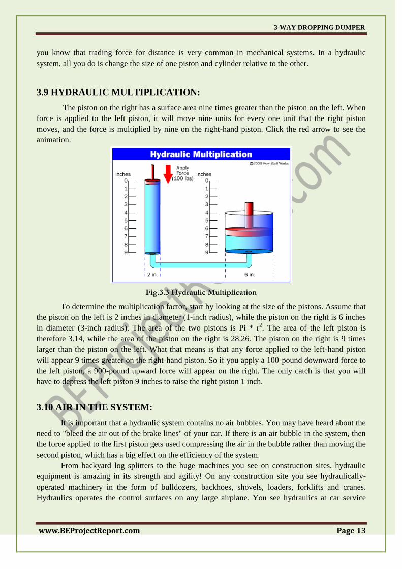
3.9 HYDRAULIC MULTIPLICATION:
The piston on the right has a surface area nine times greater than the piston on the left. When
force is applied to the left piston, it will move nine units for every one unit that the right piston
moves, and the force is multiplied by nine on the right-hand piston. Click the red arrow to see the
animation.
Fig.3.3 Hydraulic Multiplication
To determine the multiplication factor, start by looking at the size of the pistons. Assume that
the piston on the left is 2 inches in diameter (1-inch radius), while the piston on the right is 6 inches
in diameter (3-inch radius). The area of the two pistons is Pi * r2. The area of the left piston is
therefore 3.14, while the area of the piston on the right is 28.26. The piston on the right is 9 times
larger than the piston on the left. What that means is that any force applied to the left-hand piston
will appear 9 times greater on the right-hand piston. So if you apply a 100-pound downward force to
the left piston, a 900-pound upward force will appear on the right. The only catch is that you will
have to depress the left piston 9 inches to raise the right piston 1 inch.
3.10 AIR IN THE SYSTEM:
It is important that a hydraulic system contains no air bubbles. You may have heard about the
need to "bleed the air out of the brake lines" of your car. If there is an air bubble in the system, then
the force applied to the first piston gets used compressing the air in the bubble rather than moving the
second piston, which has a big effect on the efficiency of the system.
From backyard log splitters to the huge machines you see on construction sites, hydraulic
equipment is amazing in its strength and agility! On any construction site you see hydraulically-
operated machinery in the form of bulldozers, backhoes, shovels, loaders, forklifts and cranes.
Hydraulics operates the control surfaces on any large airplane. You see hydraulics at car service

3-WAY DROPPING DUMPER
www.BEProjectReport.com Page 14
centers lifting the cars so that mechanics can work underneath them, and many elevators are
hydraulically-operated using the same technique. Even the brakes in your car use hydraulics.
3.11 HYDRAULIC PUMPS:
One thing you can see is that the advertised "20-ton splitting force" is generous. A 4-inch
piston has an area of 12.56 square inches. If the pump generates a maximum pressure of 3,000
pounds per square inch (psi), the total pressure available is 37,680 pounds, or about 2,320 pounds
shy of 20 tons.
Another thing you can determine is the cycle time of the piston. To move a 4-inch-diameter
piston 24 inches, you need 3.14 * 22 * 24 = 301 cubic inches of oil. A gallon of oil is about 231 cubic
inches, so you have to pump almost 1.5 gallons of oil to move the piston 24 inches in one direction.
That's a fair amount of oil to pump -- think about that the next time you watch how quickly a
hydraulic backhoe or skid/loader is able to move! In our log splitter, the maximum flow rate is 11
gallons per minute. That means that it will take 10 or so seconds to draw the piston back after the log
is split, and it may take almost 30 seconds to push the piston through a tough log (because the flow
rate is lower at high pressures). Just to fill the cylinder with oil, you need at least 1.5 gallons of
hydraulic oil in the system. You can also see that one side of the cylinder has a larger capacity than
the other side, because one side has the piston shaft taking up space and the other doesn't. Therefore,
big hydraulic machines usually have:
Large appetites for hydraulic oil (100 gallons is not uncommon if there are six or eight large
hydraulic cylinders used to operate the machine.)
Large external reservoirs to hold the difference in the volume of oil displaced by the two sides of
any cylinder.
The basic principles that hydraulic systems use to do their work, and then we'll examine
several different pieces of hydraulic machinery found on a construction site. You will be amazed at
the power and versatility available with hydraulics.
The brakes in your car are a good example of a basic piston-driven hydraulic system. When
you depress the brake pedal in your car, it is pushing on the piston in the brake's master cylinder.
Four slave pistons, one at each wheel, actuate to press the brake pads against the brake rotor to stop
the car. (Actually, in almost all cars on the road today two master cylinders are driving two slave
cylinders each. That way if one of the master cylinders has a problem or springs a leak, you can still
stop the car.) In most other hydraulic systems, hydraulic cylinders and pistons are connected through
valves to a pump supplying high-pressure oil.
3.12 MARKET EXAMPLE: CAM SUPER LINE 3 WAY DUMP TRAILER
Suitable for unloading on narrow roads where turning around is impossible for example for
backfilling a side ditch and dumpling gravel to one side. A hydraulic top-opening right-side gate is
also available as an option. The gate lies flat, facilitating unloading.
3-WAY DROPPING DUMPER
www.BEProjectReport.com Page 15
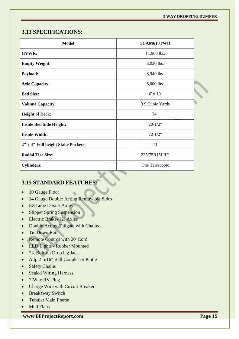
3.13 SPECIFICATIONS:
Model 5CAM610TWD
GVWR: 11,960 lbs.
Empty Weight: 3,020 lbs.
Payload: 8,940 lbs.
Axle Capacity: 6,000 lbs.
Bed Size: 6' x 10'
Volume Capacity: 3.9 Cubic Yards
Height of Deck: 34"
Inside Bed Side Height: 20-1/2"
Inside Width: 72-1/2"
2" x 4" Full height Stake Pockets: 11
Radial Tire Size: 225/75R15LRD
Cylinders: One Telescopic
3.15 STANDARD FEATURES:
10 Gauge Floor
14 Gauge Double Acting Removable Sides
EZ Lube Dexter Axles
Slipper Spring Suspension
Electric Brakes (2) Axles
Double Acting Tailgate with Chains
Tie Down Rail
Remote Control with 20' Cord
LED Lights - Rubber Mounted
7K Bolt-on Drop leg Jack
Adj. 2-5/16" Ball Coupler or Pintle
Safety Chains
Sealed Wiring Harness
7-Way RV Plug
Charge Wire with Circuit Breaker
Breakaway Switch
Tubular Main Frame
Mud Flaps
3-WAY DROPPING DUMPER
www.BEProjectReport.com Page 16
Trailer that's tough. One that can handle rough roads. Need a trailer that won't fold under the
pressure of a challenging load. Need a CAM Super line trailer.
CAM Super line, Inc. manufactures durable, dependable dump and construction trailers and
pickup truck dump inserts. Built for the long haul, CAM Super line trailers deliver consistent
performance today - and for years to come. Not only are you investing in a superior trailer, you're
backed by CAM's knowledgeable service network and superior warranties.
3.16 DANGERS:
1) Collisions:
Dump trucks are normally built for some amount of off-road or construction site driving; as
the driver is protected by the chassis and height of the driver's seat, bumpers are either placed high or
omitted for added ground clearance. The disadvantage is that in a collision with a standard car, the
entire motor section or luggage compartment goes under the truck. Thus the passengers in the car
could be more severely injured than would be common in a collision with another car.
2) Tipping:
Another safety consideration is the leveling of the truck before unloading. If the truck is not
parked on relatively horizontal ground, the sudden change of weight and balance due to lifting of the
skip and dumping of the material can cause the truck to slide, or even—in some light dump trucks—
to turn over.
3) Back-up accidents:
Because of their size and the difficulty of maintaining visual contact with on-foot workers,
dump trucks in car parks can be a threat, especially when backing up.[8]
Mirrors and back-up alarms
provide some level of protection, and having a spotter working with the driver also decreases back-
up injuries and fatalities.
3-WAY DROPPING DUMPER
www.BEProjectReport.com Page 17
CHAPTER 4
MATERIAL USED & ITS TECHNICAL DATA
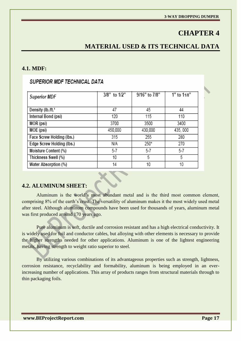
4.1. MDF:
4.2. ALUMINUM SHEET:
Aluminum is the world‘s most abundant metal and is the third most common element,
comprising 8% of the earth‘s crust. The versatility of aluminum makes it the most widely used metal
after steel. Although aluminum compounds have been used for thousands of years, aluminum metal
was first produced around 170 years ago.
Pure aluminum is soft, ductile and corrosion resistant and has a high electrical conductivity. It
is widely used for foil and conductor cables, but alloying with other elements is necessary to provide
the higher strengths needed for other applications. Aluminum is one of the lightest engineering
metals, having strength to weight ratio superior to steel.
By utilizing various combinations of its advantageous properties such as strength, lightness,
corrosion resistance, recyclability and formability, aluminum is being employed in an ever-
increasing number of applications. This array of products ranges from structural materials through to
thin packaging foils.
3-WAY DROPPING DUMPER
www.BEProjectReport.com Page 18
a) Properties of Aluminum:
The major advantages of using aluminum are tied directly to its remarkable properties. Some
of these properties are outlined in the following sections.
b) Strength to Weight Ratio:
Aluminum has a density around one third that of steel and is used advantageously in
applications where high strength and low weight are required. This includes vehicles where low mass
results in greater load capacity and reduced fuel consumption.
c) Corrosion Resistance of Aluminum:
When the surface of aluminum metal is exposed to air, a protective oxide coating forms
almost instantaneously. This oxide layer is corrosion resistant and can be further enhanced with
surface treatments such as anodizing.
d) Applications of Aluminum:
The properties of the various aluminium alloys has resulted in aluminium being used in
industries as diverse as transport, food preparation, energy generation, packaging, architecture, and
electrical transmission applications.
Depending upon the application, aluminium can be used to replace other materials like
cooper, steel, zinc, tin plate, stainless steel, titanium, wood, paper, concrete and composites.
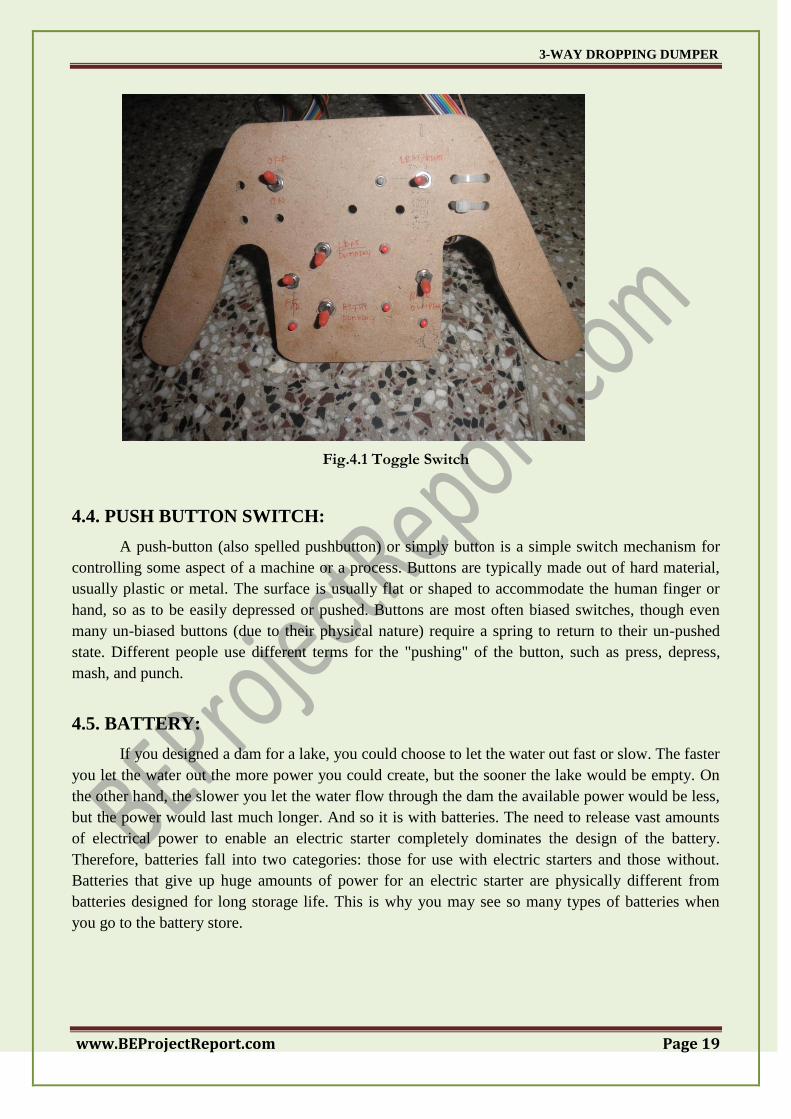
4.3. TOGGLE SWITCH:
A toggle switch is a class of electrical switches that are actuated by a mechanical lever,
handle, or rocking mechanism. Toggle switches are available in many different styles and sizes, and
are used in countless applications. Many are designed to provide, e.g., the simultaneous actuation of
multiple sets of electrical contacts, or the control of large amounts of electric current or mains
voltages. In this project the toggle switches are used to run floor cleaner vehicle in forward and
backward direction.
3-WAY DROPPING DUMPER
www.BEProjectReport.com Page 19
Fig.4.1 Toggle Switch
4.4. PUSH BUTTON SWITCH:
A push-button (also spelled pushbutton) or simply button is a simple switch mechanism for
controlling some aspect of a machine or a process. Buttons are typically made out of hard material,
usually plastic or metal. The surface is usually flat or shaped to accommodate the human finger or
hand, so as to be easily depressed or pushed. Buttons are most often biased switches, though even
many un-biased buttons (due to their physical nature) require a spring to return to their un-pushed
state. Different people use different terms for the "pushing" of the button, such as press, depress,
mash, and punch.
4.5. BATTERY:
If you designed a dam for a lake, you could choose to let the water out fast or slow. The faster
you let the water out the more power you could create, but the sooner the lake would be empty. On
the other hand, the slower you let the water flow through the dam the available power would be less,
but the power would last much longer. And so it is with batteries. The need to release vast amounts
of electrical power to enable an electric starter completely dominates the design of the battery.
Therefore, batteries fall into two categories: those for use with electric starters and those without.
Batteries that give up huge amounts of power for an electric starter are physically different from
batteries designed for long storage life. This is why you may see so many types of batteries when
you go to the battery store.
3-WAY DROPPING DUMPER
www.BEProjectReport.com Page 20
A) Types of Batteries:
a) Unsealed Batteries: The older generation batteries we‘ve all had experience with are called
―flooded cells‖. These lead-acid batteries have a supply of electrolyte (battery acid) that is boiled off
over time and must be manually replaced. Because of the loss of liquid, the cells must have an access
cap to allow the owner to add water. These batteries also have a vent hose and huge electrical
terminals. There is only one type, and they are prescribed for both kick-start and electric-start
motorcycles.
b) Sealed Batteries: Any battery without the fill caps is a ―sealed battery‖, regardless of its other
design characteristics. Within this large group of new generation batteries are found several designs
for numerous electrical duties. The modern maintenance-free design is achieved by keeping the
minimal contents under a slight pressure. This pressure helps any gases condense back into liquid
and flow back onto the battery plates. The result is that over the life of the battery so little acid is lost
that it simply doesn‘t need to be replenished.
The battery used in the project in a shield make China Made, 6V DC, 4 Ah, output solid state battery.
4.6. DC MOTOR:
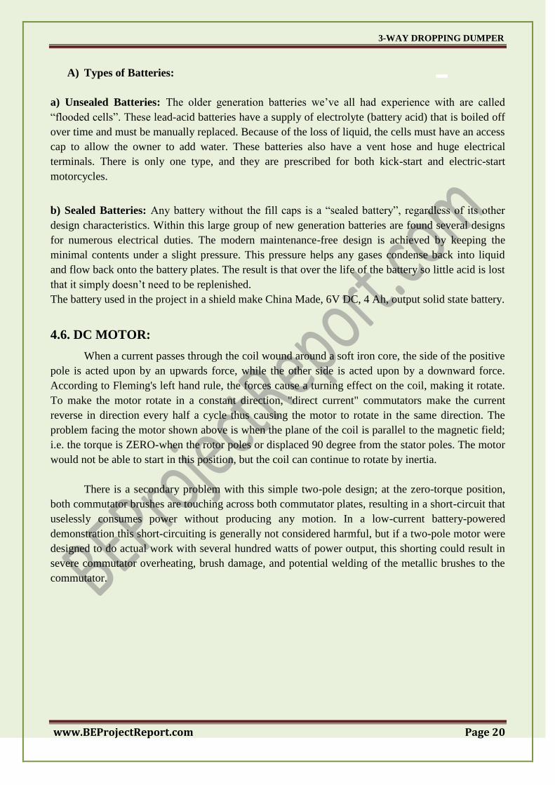
When a current passes through the coil wound around a soft iron core, the side of the positive
pole is acted upon by an upwards force, while the other side is acted upon by a downward force.
According to Fleming's left hand rule, the forces cause a turning effect on the coil, making it rotate.
To make the motor rotate in a constant direction, "direct current" commutators make the current
reverse in direction every half a cycle thus causing the motor to rotate in the same direction. The
problem facing the motor shown above is when the plane of the coil is parallel to the magnetic field;
i.e. the torque is ZERO-when the rotor poles or displaced 90 degree from the stator poles. The motor
would not be able to start in this position, but the coil can continue to rotate by inertia.
There is a secondary problem with this simple two-pole design; at the zero-torque position,
both commutator brushes are touching across both commutator plates, resulting in a short-circuit that
uselessly consumes power without producing any motion. In a low-current battery-powered
demonstration this short-circuiting is generally not considered harmful, but if a two-pole motor were
designed to do actual work with several hundred watts of power output, this shorting could result in
severe commutator overheating, brush damage, and potential welding of the metallic brushes to the
commutator.
3-WAY DROPPING DUMPER
www.BEProjectReport.com Page 21
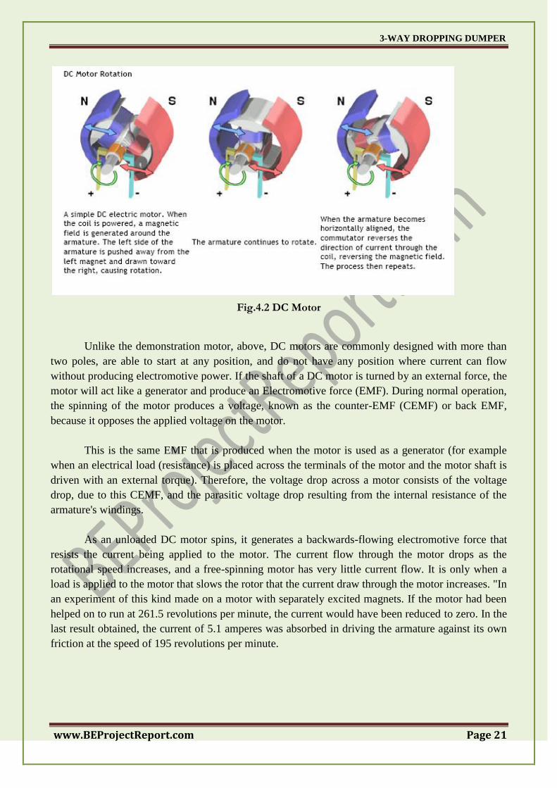
Fig.4.2 DC Motor
Unlike the demonstration motor, above, DC motors are commonly designed with more than
two poles, are able to start at any position, and do not have any position where current can flow
without producing electromotive power. If the shaft of a DC motor is turned by an external force, the
motor will act like a generator and produce an Electromotive force (EMF). During normal operation,
the spinning of the motor produces a voltage, known as the counter-EMF (CEMF) or back EMF,
because it opposes the applied voltage on the motor.
This is the same EMF that is produced when the motor is used as a generator (for example
when an electrical load (resistance) is placed across the terminals of the motor and the motor shaft is
driven with an external torque). Therefore, the voltage drop across a motor consists of the voltage
drop, due to this CEMF, and the parasitic voltage drop resulting from the internal resistance of the
armature's windings.
As an unloaded DC motor spins, it generates a backwards-flowing electromotive force that
resists the current being applied to the motor. The current flow through the motor drops as the
rotational speed increases, and a free-spinning motor has very little current flow. It is only when a
load is applied to the motor that slows the rotor that the current draw through the motor increases. "In
an experiment of this kind made on a motor with separately excited magnets. If the motor had been
helped on to run at 261.5 revolutions per minute, the current would have been reduced to zero. In the
last result obtained, the current of 5.1 amperes was absorbed in driving the armature against its own
friction at the speed of 195 revolutions per minute.
3-WAY DROPPING DUMPER
www.BEProjectReport.com Page 22
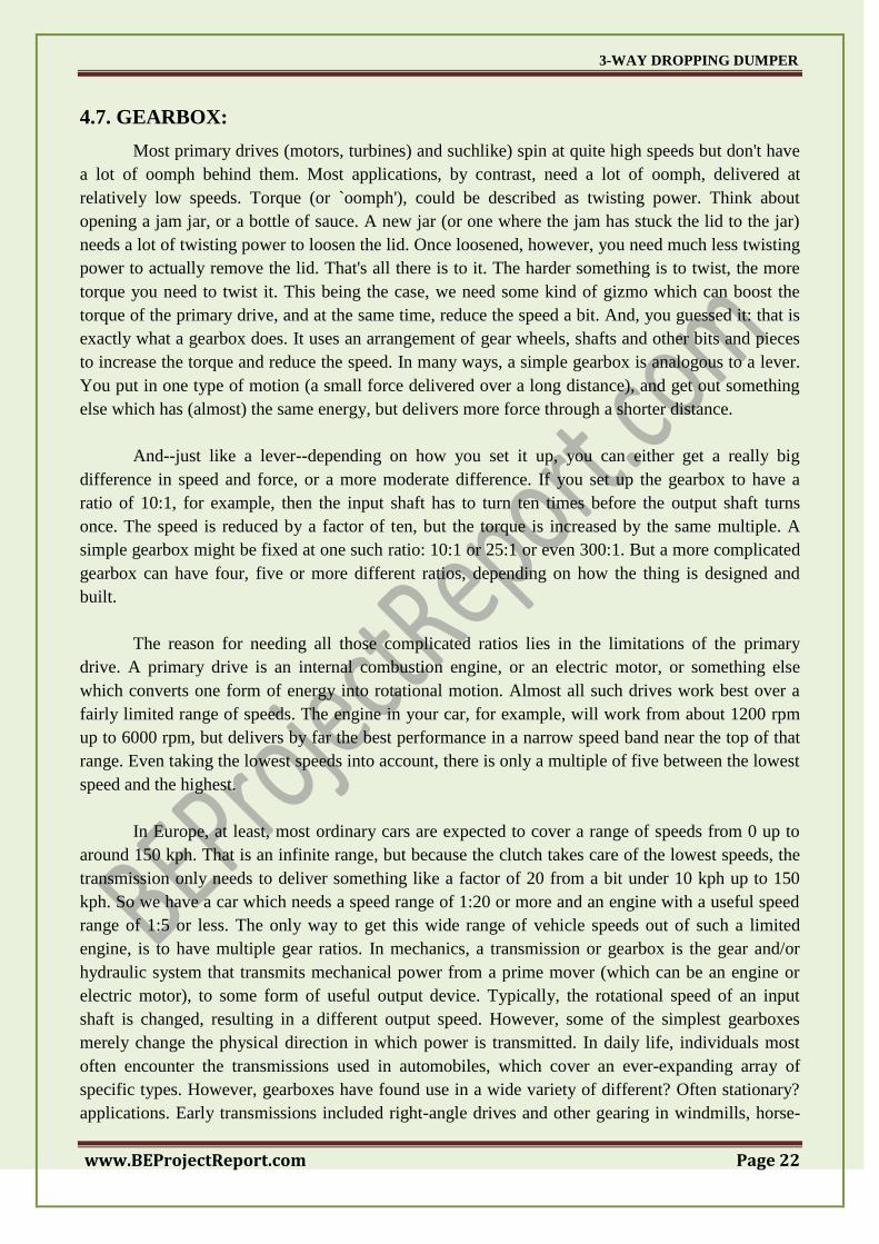
4.7. GEARBOX:
Most primary drives (motors, turbines) and suchlike) spin at quite high speeds but don't have
a lot of oomph behind them. Most applications, by contrast, need a lot of oomph, delivered at
relatively low speeds. Torque (or `oomph'), could be described as twisting power. Think about
opening a jam jar, or a bottle of sauce. A new jar (or one where the jam has stuck the lid to the jar)
needs a lot of twisting power to loosen the lid. Once loosened, however, you need much less twisting
power to actually remove the lid. That's all there is to it. The harder something is to twist, the more
torque you need to twist it. This being the case, we need some kind of gizmo which can boost the
torque of the primary drive, and at the same time, reduce the speed a bit. And, you guessed it: that is
exactly what a gearbox does. It uses an arrangement of gear wheels, shafts and other bits and pieces
to increase the torque and reduce the speed. In many ways, a simple gearbox is analogous to a lever.
You put in one type of motion (a small force delivered over a long distance), and get out something
else which has (almost) the same energy, but delivers more force through a shorter distance.
And--just like a lever--depending on how you set it up, you can either get a really big
difference in speed and force, or a more moderate difference. If you set up the gearbox to have a
ratio of 10:1, for example, then the input shaft has to turn ten times before the output shaft turns
once. The speed is reduced by a factor of ten, but the torque is increased by the same multiple. A
simple gearbox might be fixed at one such ratio: 10:1 or 25:1 or even 300:1. But a more complicated
gearbox can have four, five or more different ratios, depending on how the thing is designed and
built.
The reason for needing all those complicated ratios lies in the limitations of the primary
drive. A primary drive is an internal combustion engine, or an electric motor, or something else
which converts one form of energy into rotational motion. Almost all such drives work best over a
fairly limited range of speeds. The engine in your car, for example, will work from about 1200 rpm
up to 6000 rpm, but delivers by far the best performance in a narrow speed band near the top of that
range. Even taking the lowest speeds into account, there is only a multiple of five between the lowest
speed and the highest.
In Europe, at least, most ordinary cars are expected to cover a range of speeds from 0 up to
around 150 kph. That is an infinite range, but because the clutch takes care of the lowest speeds, the
transmission only needs to deliver something like a factor of 20 from a bit under 10 kph up to 150
kph. So we have a car which needs a speed range of 1:20 or more and an engine with a useful speed
range of 1:5 or less. The only way to get this wide range of vehicle speeds out of such a limited
engine, is to have multiple gear ratios. In mechanics, a transmission or gearbox is the gear and/or
hydraulic system that transmits mechanical power from a prime mover (which can be an engine or
electric motor), to some form of useful output device. Typically, the rotational speed of an input
shaft is changed, resulting in a different output speed. However, some of the simplest gearboxes
merely change the physical direction in which power is transmitted. In daily life, individuals most
often encounter the transmissions used in automobiles, which cover an ever-expanding array of
specific types. However, gearboxes have found use in a wide variety of different? Often stationary?
applications. Early transmissions included right-angle drives and other gearing in windmills, horse-
3-WAY DROPPING DUMPER
www.BEProjectReport.com Page 23
powered devices, and steam engines, mainly in support of pumping, milling, and hoisting
applications.
a) Simple Transmission:
The simplest transmissions, often called gearboxes to reflect their simplicity (although
complex systems are also called gearboxes on occasion), provide gear reduction (or, more rarely, an
increase in speed), sometimes in conjunction with a right-angle change in direction of the shaft.
These are often used on PTO-powered agricultural equipment, since the axial PTO shaft is at odds
with the usual need for the driven shaft, which is either vertical (as with rotary mowers), or
horizontally extending from one side of the implement to another (as with manure spreaders, flail
mowers, and forage wagons). More complex equipment, such as silage choppers and snow blowers,
has drives with outputs in more than one direction. Regardless of where they are used, these simple
transmissions all share an important feature: the gear ratio cannot be changed during use. It is fixed
at the time the transmission is constructed.
b) Multi-Ratio Systems:
Many applications require the availability of multiple gear ratios. Often, this is to ease the
starting and stopping of a mechanical system, though another important need is that of maintaining
good fuel economy.
3-WAY DROPPING DUMPER
www.BEProjectReport.com Page 24
CHAPTER 5
CONSTRUCTION AND WORKING
The project work is constructed using various material like MDF (Medium density fiber core
hard wood plywood, 3/16 nuts & bolts, aluminum sheet, motors (DC), gearboxes, syringes, wheel
screw, nuts, toggle switches, push buttons, battery etc.)
First of all a base chassis structure is prepared using MDF 8mm sheet. The structure is 22‖ in
length and 11‖ in width. This structure incorporates driving motor along with steering motor. These
motors are fixed with a fixed reduction radio gearbox of 100:1 to increase torque and reduce speed of
the motor. The wheel base is kept 14‖ while the track distance to the output slate of the gearbox
which is associated with the driving DC motor this motor and gearbox assembly is fixed in the wheel
hub. This is attached with the chassis using aluminum attachment. A steering rod connects both the
wheels which in the truck is connected with a steering motor.
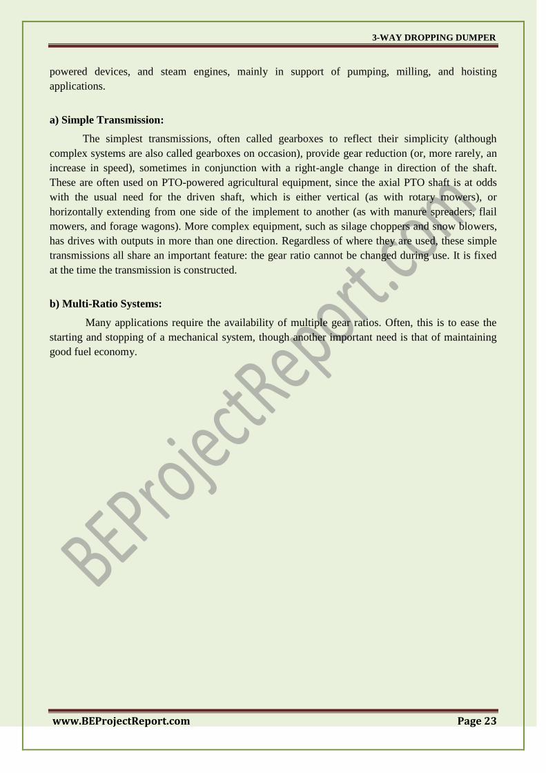
At the end of this chassis a platform of 26 x 36 cm such these platforms are pivoted on each
and off opposite sides. So as to four ‗Z‘ shaped. Each two platforms are connected using a plastic
syringe piston and cylinder assembly that forms the hydraulic piston and cylinder arrangement.
Hydraulic fluid in this piston and cylinder arrangement that is pushed and pulled using a head screw
arrangement. That is made to run to a flow using gearbox and motor. For the proper guide ways and
guide slides are used for the same thing.
This assembly is made in three numbers as there are three number of hydraulic cylinder that
operated the trolley this power cylinder and piston arrangement is fitted in front of the trolley that is
situated at the back of the chassis member.
Fig. 5.1 Left Side Dumping Action
3-WAY DROPPING DUMPER
www.BEProjectReport.com Page 25
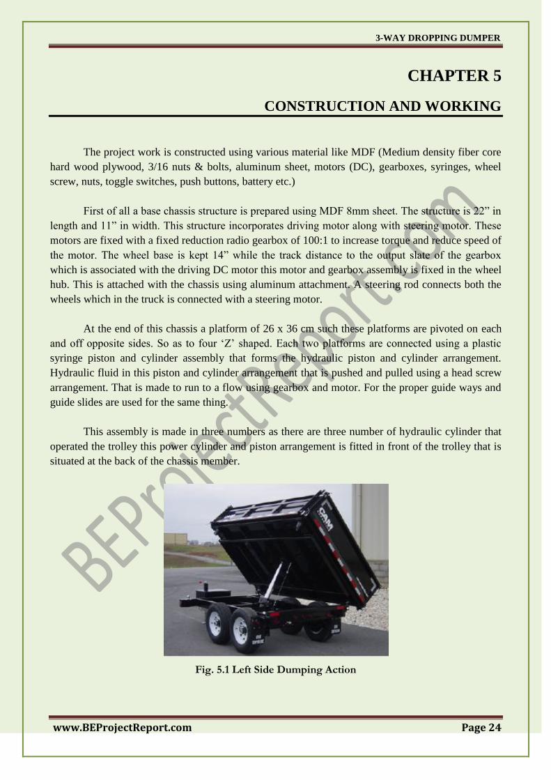
These motors are connected to the wired remote that incorporated toggle switches and push
button by manipulating these buttons the entire project work can be demonstrated and made to work.
Fig. 5.2 Right Side Dumping Action
When the operator pushes the push button the motor operated the piston and cylinder
arrangement that pushes the hydraulic fluid to the cylinder beneath. The trolley this piston gets out
and pushes the trolley to tilt by operating various cylinders the material can be dropped in 3 ways.
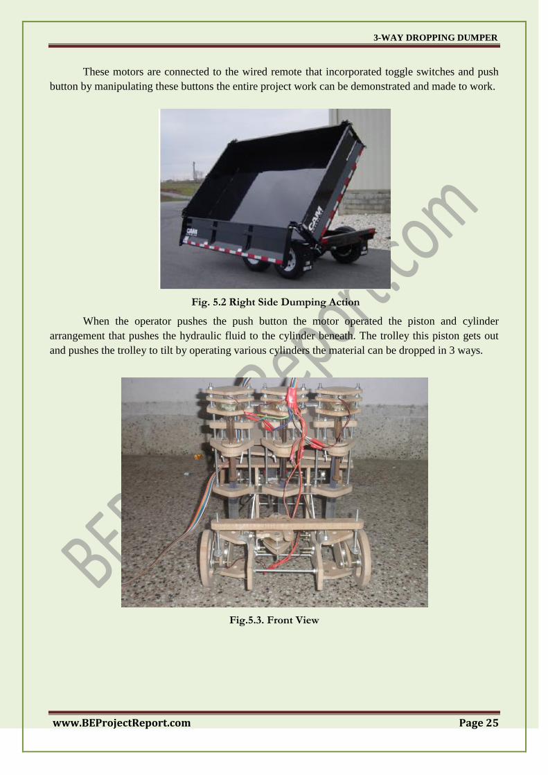
Fig.5.3. Front View
3-WAY DROPPING DUMPER
www.BEProjectReport.com Page 26
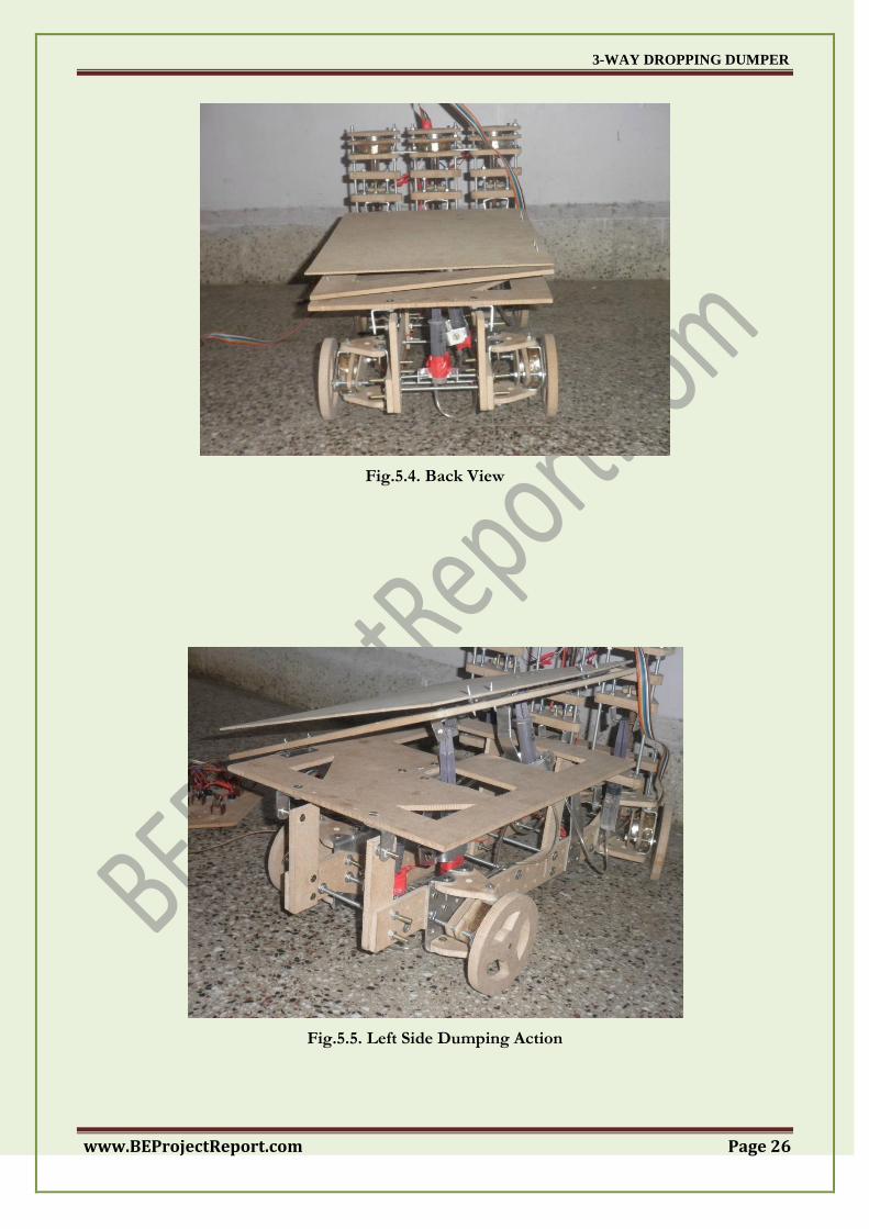
Fig.5.4. Back View
Fig.5.5. Left Side Dumping Action
3-WAY DROPPING DUMPER
www.BEProjectReport.com Page 27
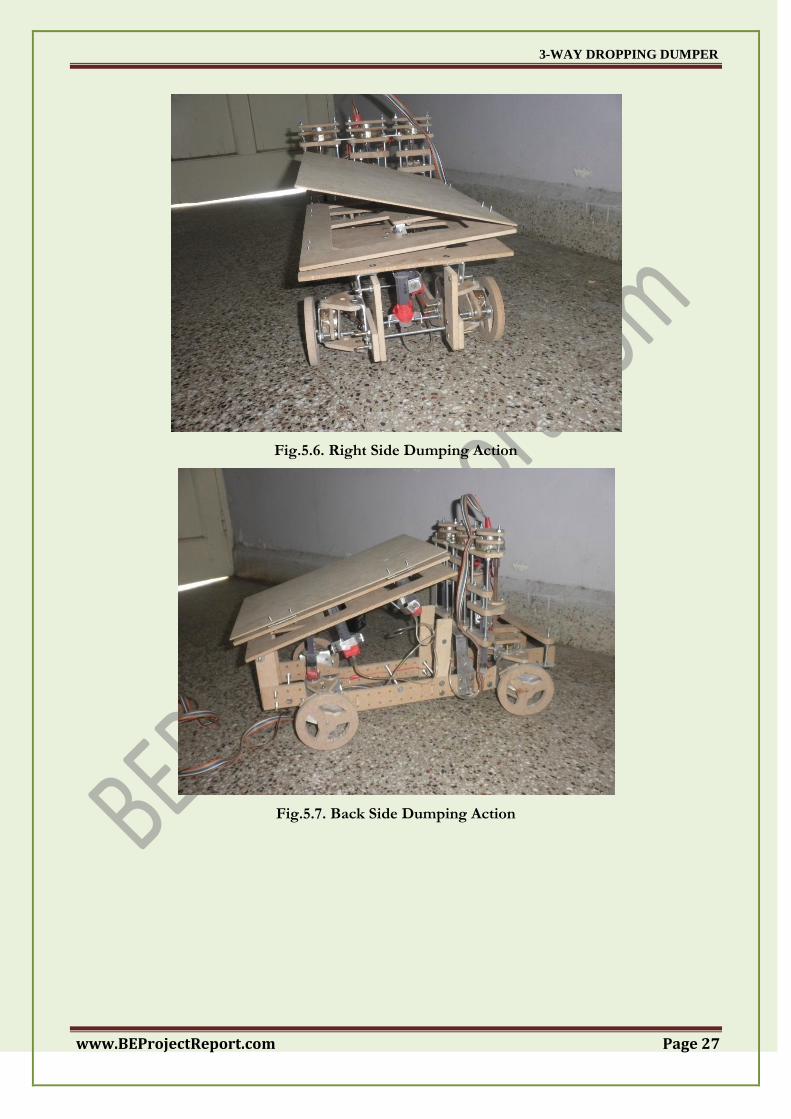
Fig.5.6. Right Side Dumping Action
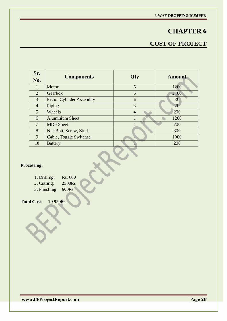
Fig.5.7. Back Side Dumping Action
3-WAY DROPPING DUMPER
www.BEProjectReport.com Page 28
CHAPTER 6
COST OF PROJECT
Sr.
No. Components Qty Amount
1 Motor 6 1200
2 Gearbox 6 2400
3 Piston Cylinder Assembly 6 30
4 Piping 3 20
5 Wheels 4 200
6 Aluminium Sheet 1 1200
7 MDF Sheet 1 700
8 Nut-Bolt, Screw, Studs - 300
9 Cable, Toggle Switches - 1000
10 Battery 1 200
Processing:
1. Drilling: Rs: 600
2. Cutting: 2500Rs
3. Finishing: 600Rs
Total Cost: 10,950Rs
3-WAY DROPPING DUMPER
www.BEProjectReport.com Page 29
CHAPTER 7
ADVANTAGES AND DISADVANTAGES
ADVANTAGES:
1. Increased moving ability :
Thus, it does not become tiresome to perform the job.
2. Can be used in very compact places :
Where the reversing & turning of vehicle is difficult.
3. Can accommodate into pass on dam site working :
4. Saves time & energy.
DISADVANTAGES:
1. Increased complexity:
As it requires complex mechanism for getting desired output.
2. Cost increases :
As more will be the complications to perform the operation, more will be the cost
encountered with it.
3. Maintenance increases :
More parts in working leads to more maintenance.
3-WAY DROPPING DUMPER
www.BEProjectReport.com Page 30
CHAPTER 8
FUTURE MODIFICATION
The project work can be modified further more on following basis:-
1. Dual stage cylinders can be used.
2. Oil pump can be used instead of powered cylinder.
3. Capacity can be increased.
4. For wheel steering can be adopted for more movement ability
As the world is progressing at faster rate we meet mover and mover huge construction which
head to be dig big and big amount of the earth and thus more efficiently working equipments are to
be required and hence the three way dropping dumper may be used more than the two way or one
way.
India is progressing at higher rate and hence infrastructural development is on its high that‘s
why efficient and working equipment that are time as well as required at larger scale also we have
very low road space in areas like Kashmir working to be efficient, also in dam site these 3 way
dropping dumper is required so the Indian context of view of the project work.
Hence the future of this project work seems promising.
3-WAY DROPPING DUMPER
www.BEProjectReport.com Page 31
CHAPTER 9
CONCLUSION
The project work thus constructed exhibits the expected results. After few further
modifications and working on disadvantages will put this project work in the main league of use. As
this concept saves time & energy as well this may leads to efficient working, which helps in the early
completion of project.
The constructional work or the infrastructural work demands of efficient and user friendly
machinery will lead to more and more use of the project work like three way dropping dumper.
3-WAY DROPPING DUMPER
www.BEProjectReport.com Page 32
BIBLIOGRAPHY
1. www.shanafelt.com/material-handling-containers.html
2. www.lislesurplus.com/.../8-x-14-x-2-bumper-pull-dump-trailer-drop-sides-7ton/
3. www.northpoint-auto.com/np/LinkClick.aspx?fileticket...tabid=40
4. www.racingjunk.com/.../3-Way-Dump-Trailer-Dumps-Left-Right-amp-Ba.html
5. www.4cstrailersdirect.com/products.php?product=2011... – Canada
6. www.tradekey.com › Products
7. www.tractorbynet.com › ... › Trailers & Transportation