Embed Size (px)
Citation preview
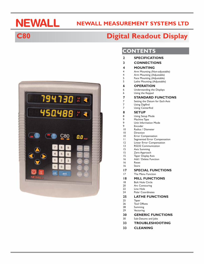
C80 Digital Readout Display
NEWALL MEASUREMENT SYSTEMS LTD
CONTENTS2 SPECIFICATIONS
3 CONNECTIONS
4 MOUNTING 4 Arm Mounting (Non-adjustable) 4 Arm Mounting (Adjustable) 5 Face Mounting (Adjustable) 5 Lathe Mounting (Adjustable)
6 OPERATION 6 Understanding the Displays 6 Using the Keypad
7 STANDARD FUNCTIONS 7 Setting the Datum for Each Axis 7 Using Digifind 7 Using Centerfind
8 SETUP 8 Using Setup Mode 9 Machine Type 9 Unit Information Mode 9 Encoder 10 Radius / Diameter 10 Direction 10 Error Compensation 11 Segmented Error Compensation 12 Linear Error Compensation 13 RS232 Communication 15 Axis Summing15 Zero Approach 15 Taper Display Axis 16 Add / Delete Function 16 Reset 16 Store
17 SPECIAL FUNCTIONS 17 The Menu Function
18 MILL FUNCTIONS18 Bolt Hole Circle 20 Arc Contouring22 Line Hole 24 Polar Coordinates
25 LATHE FUNCTIONS 25 Taper 26 Tool Offsets 28 Summing 29 Vectoring
30 GENERIC FUNCTIONS 30 Sub-Datums and Jobs
33 TROUBLESHOOTING
33 CLEANING
N
SPECIFICATIONS
SPECIFICATIONS C80 Digital Readout Display
Newall Measurement Systems Ltd2
Electrical EMC and Low Voltage Compliance
BS EN 55022:1998 Class B
BS EN 55024:1998
Power Supply Unit (supplied) 100 - 240V (47 - 63Hz) External switch-mode
Conforms to Low Voltage DirectiveEN 60 950:1992/ A1:1993/ A2:1994/ A3:1996/ A4:1997
PhysicalHeight
265mm (10.43”)
Width180mm (7.09”)
Depth (not including connectors)50mm (1.97”)
Weight2.9kg (6.38lb)
EnvironmentalOperating Temperature
0 to 45°C
Storage Temperature-20 to 70°C
Environmental ConditionsIndoor Use, IP20 (IEC 529)
Relative HumidityMaximum 80% for temperatures up to 31°Cdecreasing linearly to 33% at 45°C
DisposalAt the end of its life, the C80 system should bedisposed of in a safe manner applicable toelectronic goods.
DO NOT BURN.
The casework is suitable for recycling. Please
consult local regulations on disposal of
electrical equipment.
InputThree Spherosyn or Microsyn encoders.
ResolutionsSpherosyn or Microsyn 10
(menu selection)
5µm (0.0002”)
10µm (0.0005”)
20µm (0.001”)
50µm (0.002”)
Microsyn 5(menu selection)
1µm (0.00005”)
2µm (0.0001”)
5µm (0.0002”)
10µm (0.0005”)
NOTE: NEWALL MEASUREMENT SYSTEMS LTD RESERVES THE RIGHT TO CHANGE SPECIFICATIONS WITHOUT NOTICE.
NOTES
Certificate No FM36096
C80 Digital Readout Display
CONNECTIONS
Newall Measurement Systems Ltd 3
NOTES
DO NOT CONNECTTHIS UNIT DIRECTLYTO THE MAINS SUPPLY.
If you have a Newallencoder which is not fittedwith D-type connector, anadaptor cable is available.
Part No. 307-80980
Contact your supplier fordetails.
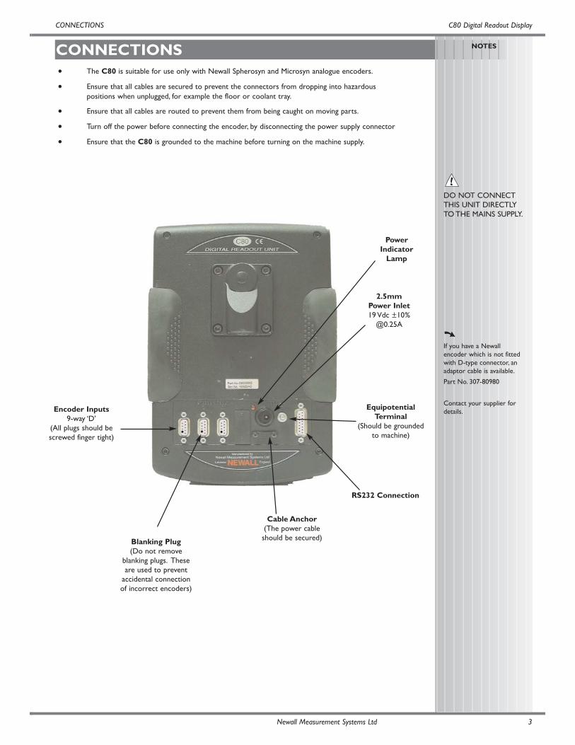
2.5mm Power Inlet19 Vdc ±10%
@0.25A
PowerIndicator
Lamp
Encoder Inputs9-way ‘D’
(All plugs should bescrewed finger tight)
EquipotentialTerminal
(Should be groundedto machine)
Cable Anchor(The power cableshould be secured)
• The C80 is suitable for use only with Newall Spherosyn and Microsyn analogue encoders.
• Ensure that all cables are secured to prevent the connectors from dropping into hazardous positions when unplugged, for example the floor or coolant tray.
• Ensure that all cables are routed to prevent them from being caught on moving parts.
• Turn off the power before connecting the encoder, by disconnecting the power supply connector
• Ensure that the C80 is grounded to the machine before turning on the machine supply.
CONNECTIONS
Blanking Plug(Do not remove
blanking plugs. Theseare used to prevent
accidental connectionof incorrect encoders)
RS232 Connection
Arm Mounting (Non-adjustable)
Arm Mounting (Adjustable)
Face Mounting (Adjustable)
MOUNTING
MOUNTING,Arm Mounting , Face Mounting C80 Digital Readout Display
NOTES
Newall Measurement Systems Ltd4
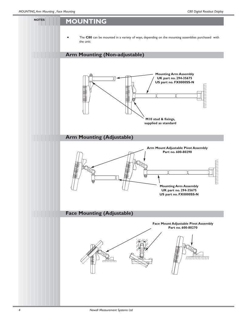
• The C80 can be mounted in a variety of ways, depending on the mounting assemblies purchased with the unit:
M10 stud & fixings,supplied as standard
Arm Mount Adjustable Pivot AssemblyPart no. 600-80290
Mounting Arm AssemblyUK part no. 294-35675
US part no. FX0000SS-N
Mounting Arm AssemblyUK part no. 294-35675
US part no. FX0000SS-N
Face Mount Adjustable Pivot AssemblyPart no. 600-80270
C80 Digital Readout Display
Lathe Mounting (Adjustable)
MOUNTING, Lathe Mounting
Newall Measurement Systems Ltd 5
Lathe Mounting (Adjustable) With Arm Assembly
NOTES
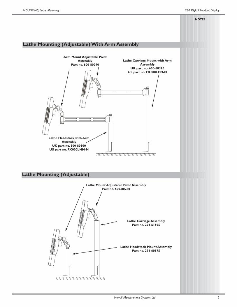
Lathe Mount Adjustable Pivot AssemblyPart no. 600-80280
Lathe Carriage AssemblyPart no. 294-61695
Lathe Headstock Mount AssemblyPart no. 294-60675
Lathe Carriage Mount with ArmAssembly
UK part no. 600-80310US part no. FX000LCM-N
Arm Mount Adjustable PivotAssembly
Part no. 600-80290
Lathe Headstock with ArmAssembly
UK part no. 600-80300US part no. FX000LHM-N
Understanding the Displays
Using the Keypad
OPERATION
OPERATION, Understanding the Displays, Using the Keypad C80 Digital Readout Display
NOTES
During Setup and SpecialFunctions, the displays mayshow information otherthan that described on thispage.
See the sections on Setupand Special Functions,later in this guide.
For more information aboutthe use of the NavigationKeys and the FunctionKeys, see the sections onSetup and SpecialFunctions, later in thisguide.
During Setup and SpecialFunctions, the keys may beused for functions otherthan those described on thispage.
See the sections on Setupand Special Functions,later in this guide.
At the beginning of eachworking session, set thedatum in Absolute Mode,then switch the C80 toIncremental Mode.
By using the C80 in thisway, you will be able toreturn the machine to itsabsolute datum at any time,simply by switching back toAbsolute Mode.
Newall Measurement Systems Ltd6
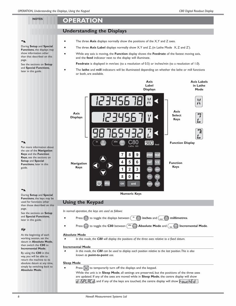
• The three Axis displays normally show the positions of the X,Y and Z axes.
• The three Axis Label displays normally show X,Y and Z, (in Lathe Mode X, Z and Z’).
• While any axis is moving, the Function display shows the Feedrate of the fastest moving axis,and the feed indicator next to the display will illuminate.
Feedrate is displayed in mm/sec (to a resolution of 0.5) or inches/min (to a resolution of 1.0).
• The lathe and mill indicators will be illuminated depending on whether the lathe or mill functions or both, are available.
Function Display
NavigationKeys
Numeric Keys
FunctionKeys
AxisSelectKeys
AxisLabel
Displays
Axis Labelsin Lathe
Mode
AxisDisplays
In normal operation, the keys are used as follows:
• Press to toggle the displays between inches and millimetres.
• Press to toggle the C80 between Absolute Mode and Incremental Mode.
Absolute Mode• In this mode, the C80 will display the positions of the three axes relative to a fixed datum.
Incremental Mode• In this mode, the C80 can be used to display each position relative to the last position.This is also
known as point-to-point use.
Sleep Mode
• Press to temporarily turn off the displays and the keypad.
While the unit is in Sleep Mode, all settings are preserved, but the positions of the three axes are updated. If any of the axes are moved while in Sleep Mode, the centre display will show
, and if any of the keys are touched, the centre display will show .
Centerfind works by halving the distance displayed on the selected axis. It works in either Absolute or IncrementalMode.
For Example: to find the center of a workpiece that is 100mm wide:
• Set the tool to one edge of the workpiece, and press the Select Key for the axis to be
centered.The display shows .
• Set the tool to the other edge of the workpiece.The display shows .
• Press The display shows ‘0’ in all axes. Press the Select Key for the axis to be centered.
The display will now show .
• Move the tool until the display shows . This is the center of the workpiece.
C80 Digital Readout Display
Using Centerfind
Using Digifind
Setting the Datum for Each Axis
STANDARD FUNCTIONS
STANDARD FUNCTIONS, Setting the Datum, Digifind, Centerfind
NOTES
Using Zero redefines thedatum, so it will not bepossible to restore the olddatum.
Using Preset, Recall orCenterfind will change thedatum - but in AbsoluteMode, Digifind can still beused to return to the olddatum.
Do not move the machinewhen the C80’s power isoff.
When the power isswitched back on again, theC80 uses Digifindautomatically to re-establishthe datum for each axis.
Digifind works only inAbsolute Mode.
Set the C80 toIncremental before usingCenterfind.
By doing this, you will beable to return the machineto its absolute datumafterwards, simply byswitching back to AbsoluteMode.
Newall Measurement Systems Ltd 7
Zero• To zero one display at the current position:
Press the Select Key for the axis to be zeroed.All readings will now be relative to this new zero
point.
Preset• To preset one display to a known fixed value:
Press , then the Select Key for the axis to be preset, then enter the value.
For Example: Press to enter the value .All
readings will now be relative to this new value.
• If you make a mistake while entering a number, pressing will clear the entry one character
at a time.
Recall• To quickly recall the last preset value for an axis:
Press , then the Select Key for the axis to be preset.All readings will now be relative
to this new value.
In the event that a datum is lost, either due to movement following a power failure, or after a fixed point has been entered bymistake, it can easily be re-established, using Digifind.
In order to use Digifind, the absolute datum for each axis should be marked permanently on themachine.
• Set the axis close to the marked datum - to within:6.3mm (0.25”) for a Spherosyn encoder or2.5mm (0.1”) for a Microsyn encoder.
• Switch the C80 to Absolute Mode.
• Press , then the Select Key for the axis to be restored.The display will update to
show the exact distance from the datum.
SETUP
Using Setup Mode
SETUP, Using Setup Mode C80 Digital Readout Display
NOTES
Normally, Setup needs tobe done only once, and it ispossible that the factorydefault settings will besuitable and will not requirechange.
1
Not all options will bepresent, depending on thesetting of other options.
For example, the ZeroApproach Limit optionwill not be present if ZeroApproach is turned off.
2
The Add Function andDelete Function optionsallow for the download ofprogrammable functionsfrom a PC, connected tothe C80 via a serial leadconnected to the 15Dconnection.The serial leadis an option and can beordered separately, ifrequired. Use Part No. 307-83210. Please contact yoursupplier for pricinginformation
Newall Measurement Systems Ltd8
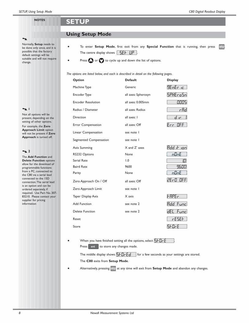
• To enter Setup Mode, first exit from any Special Function that is running, then press .
The centre display shows .
• Press or to cycle up and down the list of options.
The options are listed below, and each is described in detail on the following pages.
Option Default Display
Machine Type Generic
Encoder Type all axes: Spherosyn
Encoder Resolution all axes: 0.005mm
Radius / Diameter all axes: Radius
Direction all axes: 1
Error Compensation all axes: Off
Linear Compensation see note 1
Segmented Compensation see note 1
Axis Summing X and Z’ axes
RS232 Options None
Serial Rate 1.0
Baird Rate 9600
Parity None
Zero Approach On / Off all axes: Off
Zero Approach Limit see note 1
Taper Display Axis X axis
Add Function see note 2
Delete Function see note 2
Reset
Store
• When you have finished setting all the options, select .
Press to store any changes made.
The middle display shows for a few seconds as your settings are stored.
The C80 exits from Setup Mode.
• Alternatively, pressing at any time will exit from Setup Mode and abandon any changes.
C80 Digital Readout Display
Encoder
Machine Type
SETUP, Unit Information Mode, Machine Type, Encoder
NOTES
The Encoder settings mustmatch the actual encoder inuse, or the C80 will notdisplay correctly.
Newall Measurement Systems Ltd 9
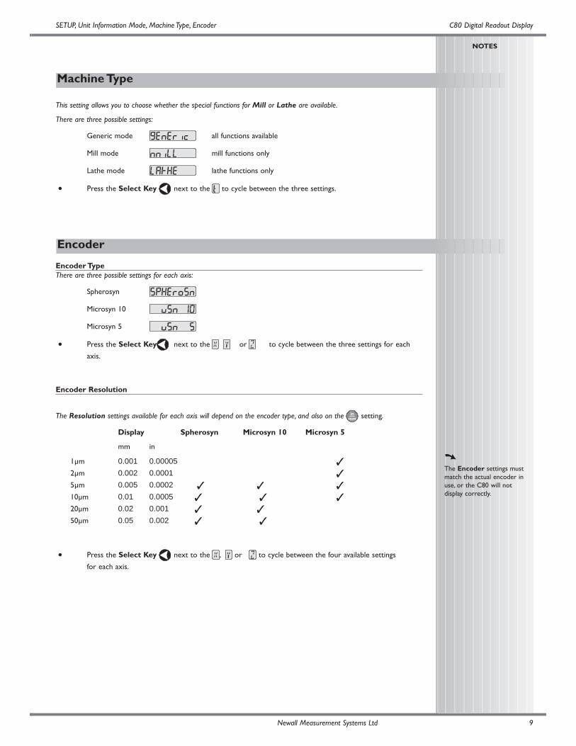
This setting allows you to choose whether the special functions for Mill or Lathe are available.
There are three possible settings:
Generic mode all functions available
Mill mode mill functions only
Lathe mode lathe functions only
• Press the Select Key next to the to cycle between the three settings.
Encoder TypeThere are three possible settings for each axis:
Spherosyn
Microsyn 10
Microsyn 5
• Press the Select Key next to the , or to cycle between the three settings for each
axis.
Encoder Resolution
The Resolution settings available for each axis will depend on the encoder type, and also on the setting.
Display Spherosyn Microsyn 10 Microsyn 5
mm in
1µm 0.001 0.000052µm 0.002 0.00015µm 0.005 0.000210µm 0.01 0.000520µm 0.02 0.00150µm 0.05 0.002
• Press the Select Key next to the , or to cycle between the four available settings
for each axis.
Error Compensation
Direction
Radius / Diameter
SETUP, Radius / Diameter, Direction, Error Compensation C80 Digital Readout Display
NOTES
The Diameter setting isuseful for lathes, and otherturning applications todisplay diameter rather thanradius.
The Direction setting isquite arbitrary. Set it towhichever makes mostsense to the machine.
Note, Direction isdependent on where thescale is mounted.
If Error Compensation isapplied, it is important thatit is absolutely correct. If itis not correct, errors couldbe increased rather thanreduced.
After setting up the ErrorCompensation, it isadvisable to check its effectin normal operation.
SegmentedCompensation need notbe over the entire scalelength.
It can be applied just to alength of high importance,or it can be as small as onesegment.
See pages 11 and 12for details on usingLinear andSegmented ErrorCompensation
Newall Measurement Systems Ltd10
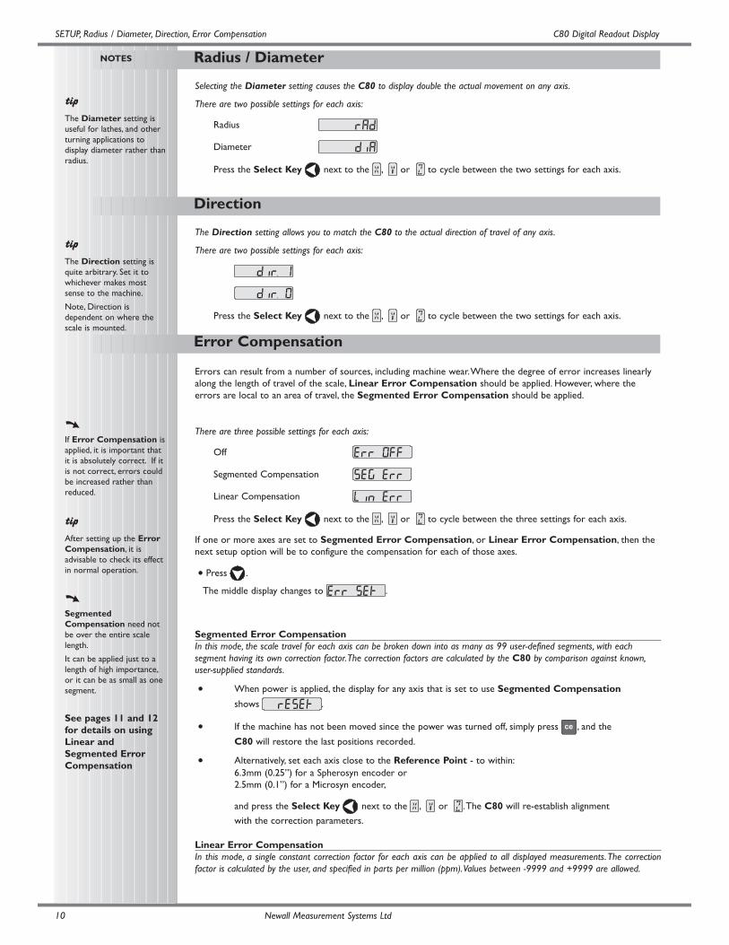
Selecting the Diameter setting causes the C80 to display double the actual movement on any axis.
There are two possible settings for each axis:
Radius
Diameter
Press the Select Key next to the , or to cycle between the two settings for each axis.
The Direction setting allows you to match the C80 to the actual direction of travel of any axis.
There are two possible settings for each axis:
Press the Select Key next to the , or to cycle between the two settings for each axis.
Errors can result from a number of sources, including machine wear.Where the degree of error increases linearlyalong the length of travel of the scale, Linear Error Compensation should be applied. However, where theerrors are local to an area of travel, the Segmented Error Compensation should be applied.
There are three possible settings for each axis:
Off
Segmented Compensation
Linear Compensation
Press the Select Key next to the , or to cycle between the three settings for each axis.
If one or more axes are set to Segmented Error Compensation, or Linear Error Compensation, then thenext setup option will be to configure the compensation for each of those axes.
• Press .
The middle display changes to .
Segmented Error CompensationIn this mode, the scale travel for each axis can be broken down into as many as 99 user-defined segments, with eachsegment having its own correction factor.The correction factors are calculated by the C80 by comparison against known,user-supplied standards.
• When power is applied, the display for any axis that is set to use Segmented Compensation
shows .
• If the machine has not been moved since the power was turned off, simply press , and the
C80 will restore the last positions recorded.
• Alternatively, set each axis close to the Reference Point - to within:6.3mm (0.25”) for a Spherosyn encoder or2.5mm (0.1”) for a Microsyn encoder,
and press the Select Key next to the , or .The C80 will re-establish alignment
with the correction parameters.
Linear Error CompensationIn this mode, a single constant correction factor for each axis can be applied to all displayed measurements.The correctionfactor is calculated by the user, and specified in parts per million (ppm).Values between -9999 and +9999 are allowed.
C80 Digital Readout Display
Segmented Error Compensation
SETUP, Segmented Error Compensation
NOTES
Up to 99 segments can bedefined per axis.
To take advantage ofSegmented ErrorCompensation, you willneed access to a highaccuracy standard, such as alaser measuring system.
Error Compensationinitially defaults to Off, withno points set.
If Error Compensation isset to Off afterCorrection Points havebeen set, the data isretained, but not applied.When Segmented ErrorCompensation is set toOn again, the data will bere-applied.
This procedure must becarried out in strictsequence, and in full, to bevalid.There must be noreversals in direction.
Pressing Select Key
at steps 1, 2 or 3, willdisplay the currentuncorrected positionrelative to the (StartingPoint).
Do not worry about thedirection of the standardmeasurement. for example,678.9 and -678.9 are treatedthe same.
Pressing will clear an
entry one character at atime.
After an entry has beencompleted by pressing
, pressing willtake you back one step at atime.
Newall Measurement Systems Ltd 11
If one or more axes are set to Segmented Error Compensation, then the following procedure should befollowed to configure the compensation for each of those axes.
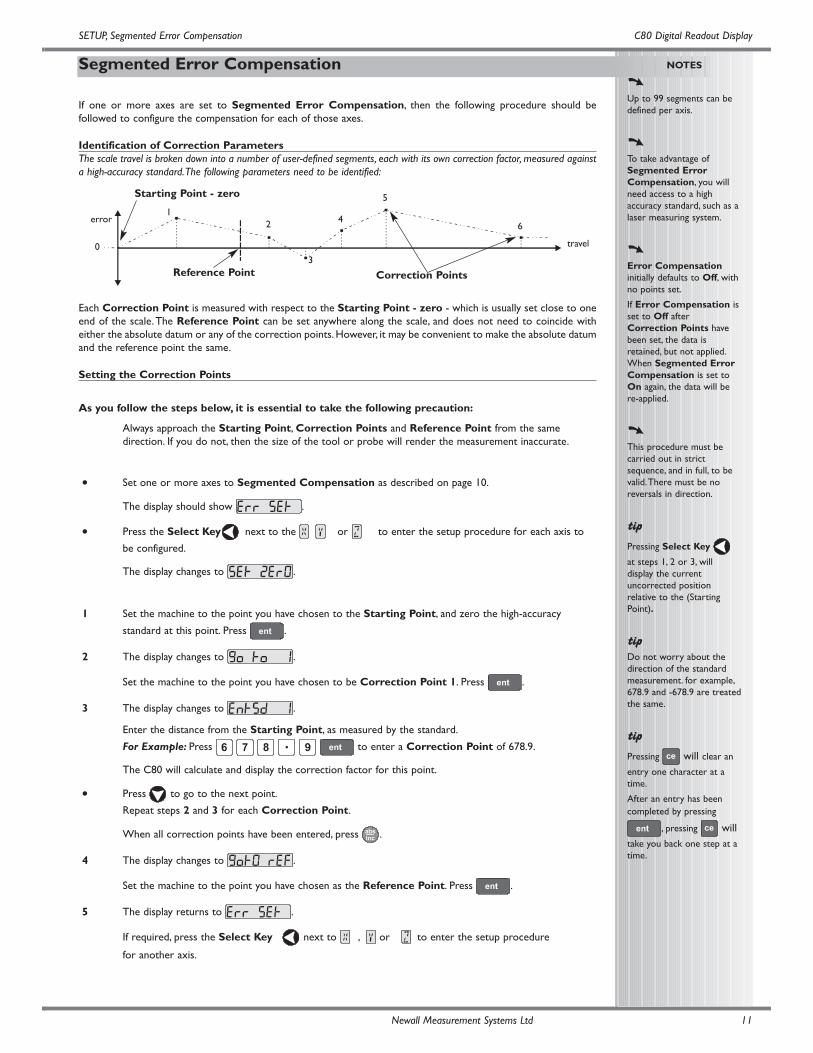
Identification of Correction ParametersThe scale travel is broken down into a number of user-defined segments, each with its own correction factor, measured againsta high-accuracy standard.The following parameters need to be identified:
error
travel
Starting Point - zero
Correction PointsReference Point
0
12
3
4
5
6
Each Correction Point is measured with respect to the Starting Point - zero - which is usually set close to oneend of the scale.The Reference Point can be set anywhere along the scale, and does not need to coincide witheither the absolute datum or any of the correction points. However, it may be convenient to make the absolute datumand the reference point the same.
Setting the Correction Points
As you follow the steps below, it is essential to take the following precaution:
Always approach the Starting Point, Correction Points and Reference Point from the same direction. If you do not, then the size of the tool or probe will render the measurement inaccurate.
• Set one or more axes to Segmented Compensation as described on page 10.
The display should show .
• Press the Select Key next to the , or to enter the setup procedure for each axis to
be configured.
The display changes to .
1 Set the machine to the point you have chosen to the Starting Point, and zero the high-accuracy
standard at this point. Press .
2 The display changes to .
Set the machine to the point you have chosen to be Correction Point 1. Press .
3 The display changes to .
Enter the distance from the Starting Point, as measured by the standard.
For Example: Press to enter a Correction Point of 678.9.
The C80 will calculate and display the correction factor for this point.
• Press to go to the next point.
Repeat steps 2 and 3 for each Correction Point.
When all correction points have been entered, press .
4 The display changes to .
Set the machine to the point you have chosen as the Reference Point. Press .
5 The display returns to .
If required, press the Select Key next to , or to enter the setup procedure
for another axis.
Linear Error Compensation
SETUP, Linear Error Compensation C80 Digital Readout Display
NOTES
The Correction Factorcannot be established whilein Setup Mode.
Carry out themeasurements in NormalOperating Mode, thenenter Setup Mode to setthe Correction Factor.
Only values between
-9999 and 9999 areallowed.
If you make a mistake whileentering a number, pressing
will clear the entry one
character at a time.
Newall Measurement Systems Ltd12
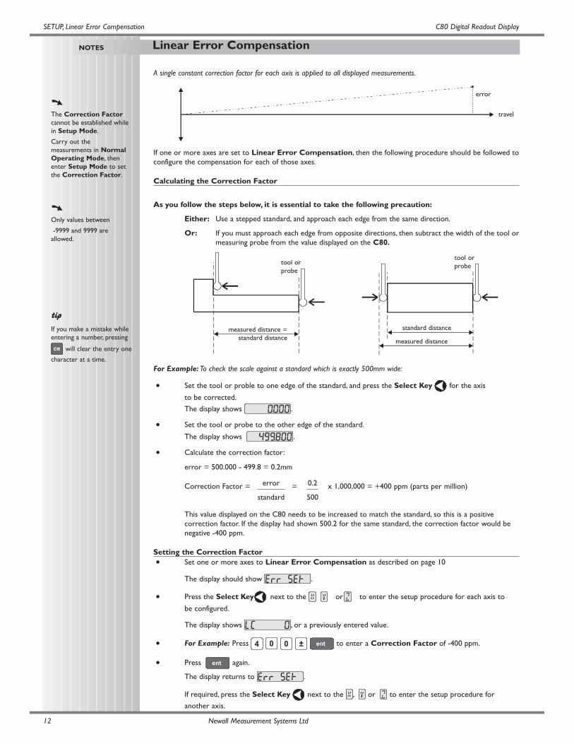
A single constant correction factor for each axis is applied to all displayed measurements.
If one or more axes are set to Linear Error Compensation, then the following procedure should be followed toconfigure the compensation for each of those axes.
Calculating the Correction Factor
As you follow the steps below, it is essential to take the following precaution:
Either: Use a stepped standard, and approach each edge from the same direction.
Or: If you must approach each edge from opposite directions, then subtract the width of the tool ormeasuring probe from the value displayed on the C80.
For Example: To check the scale against a standard which is exactly 500mm wide:
• Set the tool or proble to one edge of the standard, and press the Select Key for the axis
to be corrected.
The display shows .
• Set the tool or probe to the other edge of the standard.
The display shows .
• Calculate the correction factor:
error = 500.000 - 499.8 = 0.2mm
Correction Factor = = x 1,000,000 = +400 ppm (parts per million)
This value displayed on the C80 needs to be increased to match the standard, so this is a positive correction factor. If the display had shown 500.2 for the same standard, the correction factor would be negative -400 ppm.
Setting the Correction Factor• Set one or more axes to Linear Error Compensation as described on page 10
The display should show .
• Press the Select Key next to the , or to enter the setup procedure for each axis to
be configured.
The display shows , or a previously entered value.
• For Example: Press to enter a Correction Factor of -400 ppm.
• Press again.
The display returns to .
If required, press the Select Key next to the , or to enter the setup procedure for
another axis.
0.2
500
error
standard
error
travel
standard distancemeasured distance =standard distance
tool orprobe
tool orprobe
measured distance
13
RS232 Options
RS232 Communication C80 Digital Readout Display
NOTES
RS232 was added as astandard feature to the C80in March 2005.
Newall Measurement Systems Ltd
• The RS232 configuration settings can be found sandwiched between the Axis Summing and Zero Approach settings in the set-up structure
• The baud rates for communications are selectable from Set-up. The available baud rates are:300, 1200, 2400, 4800, 9600, 14400, 19200, 38400
• From the Set-up structure one of three RS232 modes are selectable. These are:
No RS232
• All RS232 functions are disabled and no outputs are made
• This is the default condition
Continuous Output
• From the menu structure the frequency of output is to be defined. The options of frequency are:0.1 - 60.0 in steps of 0.1 second.
Keyed Output
• When this option is selected, the axes data is transmitted when the key is pressed, without proceeding keys having been pressed. Thus this option does not require the use of a function key
Output Data Format
• The current axis data for the axes available on the system are to be transmitted
• For two axis systems, only two axes of data will be transmitted
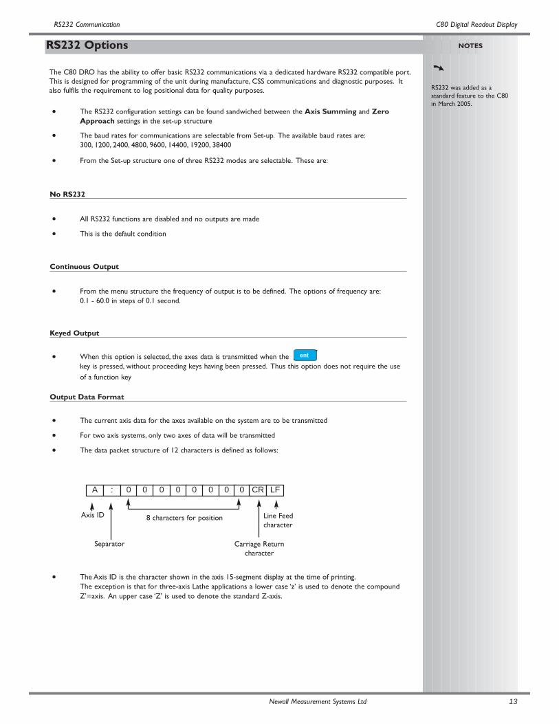
• The data packet structure of 12 characters is defined as follows:
• The Axis ID is the character shown in the axis 15-segment display at the time of printing.The exception is that for three-axis Lathe applications a lower case ‘z’ is used to denote the compound Z’=axis. An upper case ‘Z’ is used to denote the standard Z-axis.
The C80 DRO has the ability to offer basic RS232 communications via a dedicated hardware RS232 compatible port.This is designed for programming of the unit during manufacture, CSS communications and diagnostic purposes. Italso fulfils the requirement to log positional data for quality purposes.
A : 0 0 0 0 0 0 0 CR LF
Axis ID
Separator
8 characters for position
Carriage Returncharacter
Line Feedcharacter
0
14
RS232 Communication C80 Digital Readout Display
NOTES
Newall Measurement Systems Ltd
Continued
System Settings
Baud rate = Configurable (300, 1200, 2400, 4800, 9600, 14400, 19200, 38400)
Data bits = 8
Parity bit = Configurable (Even, Off, None)
Stop bits = 1
Flow control = None
Default System Settings
Serial option = None
Serial rate = 1.0 (i.e. once per second)
Baud rate = 9600
Parity bit = None
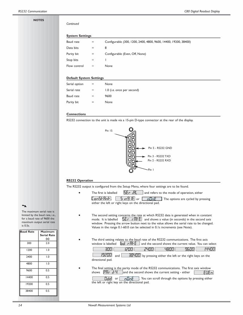
Connections
RS232 connection to the unit is made via a 15-pin D-type connector at the rear of the display.
RS232 Operation
The RS232 output is configured from the Setup Menu, where four settings are to be found.
• The first is labelled and refers to the mode of operation, either
, or . The options are cycled by pressing either the left or right keys on the directional pad.
• The second setting concerns the rate at which RS232 data is generated when in constant mode. It is labelled and shows a value (in seconds) in the second axis window. Pressing the arrow button next to the value allows the serial rate to be changed.Values in the range 0.1-60.0 can be selected in 0.1s increments (see Note).
• The third setting relates to the baud rate of the RS232 communications. The first axis window is labelled and the second shows the current value. You can select
and by pressing either the left or the right keys on the directional pad.
• The final setting is the parity mode of the RS232 communications. The first axis window shows and the second shows the current setting - either
or . You can scroll through the options by pressing either the left or right key on the directional pad.
The maximum serial rate islimited by the baud rate, i.e.,for a baud rate of 9600 themaximum output serial rateis 0.5s.
Baud Rate MaximumSerial Rate
(s)
300 2.0
1200 1.0
2400 1.0
4800 1.0
9600 0.5
14400 0.5
19200 0.5
38400 0.5
Pin 15
Pin 5 - RS232 GND
Pin 3 - RS232 TXD
Pin 2 - RS232 RXD
Pin 1
C80 Digital Readout Display
Taper Display Axis
Axis Summing
Zero Approach
SETUP,Axis Summing, Zero Approach,Taper Display, Add / Delete function
NOTES
Newall Measurement Systems Ltd 15
This setting works in conjunction with the Summing function.
• Two of the axis displays show .
Press the Select Keys or to cycle between the two settings X,Z or Z,Z’.
This setting works in conjunction with the Taper function.
• One of the axis displays shows
and the other two displays show .
Press the Select Keys or to choose which axis will display the Taper function.
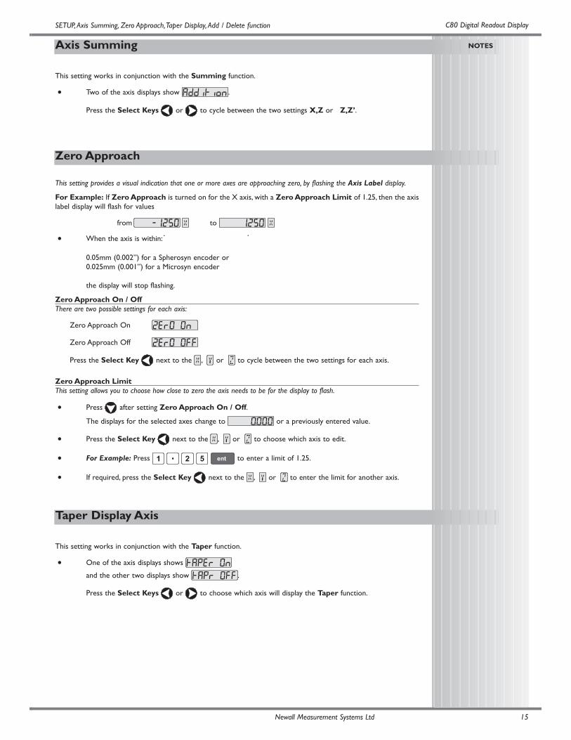
This setting provides a visual indication that one or more axes are approaching zero, by flashing the Axis Label display.
For Example: If Zero Approach is turned on for the X axis, with a Zero Approach Limit of 1.25, then the axislabel display will flash for values
from to
• When the axis is within:
0.05mm (0.002”) for a Spherosyn encoder or0.025mm (0.001”) for a Microsyn encoder
the display will stop flashing.
Zero Approach On / OffThere are two possible settings for each axis:
Zero Approach On
Zero Approach Off
Press the Select Key next to the , or to cycle between the two settings for each axis.
Zero Approach LimitThis setting allows you to choose how close to zero the axis needs to be for the display to flash.
• Press after setting Zero Approach On / Off.
The displays for the selected axes change to or a previously entered value.
• Press the Select Key next to the , or to choose which axis to edit.
• For Example: Press to enter a limit of 1.25.
• If required, press the Select Key next to the , or to enter the limit for another axis.
Store
Reset
Add / Delete Function
SPECIAL FUNCTIONS, Reset, Store C80 Digital Readout Display
NOTES
THE SERIALPROGRAMMING LEAD ISSPECIFICALLY DESIGNEDFOR CONNECTION TOC-SERIES DIGITALREADOUTS. INCORRECTCONNECTION MAYCAUSE FAILURE.
USE RESET WITHCAUTION.ALL STOREDSETTINGS WILL BE LOSTIF THIS FUNCTION ISUSED.
ALL RESTORE SETTINGSARE SAVED IMMEDIATELY.
Reset will takeapproximately 15seconds.
Newall Measurement Systems Ltd16
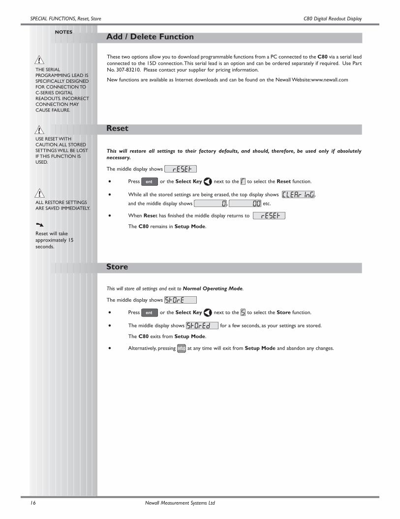
These two options allow you to download programmable functions from a PC connected to the C80 via a serial leadconnected to the 15D connection.This serial lead is an option and can be ordered separately if required. Use PartNo. 307-83210. Please contact your supplier for pricing information.
New functions are available as Internet downloads and can be found on the Newall Website:www.newall.com
This will restore all settings to their factory defaults, and should, therefore, be used only if absolutelynecessary.
The middle display shows
• Press or the Select Key next to the to select the Reset function.
• While all the stored settings are being erased, the top display shows ,
and the middle display shows , etc.
• When Reset has finished the middle display returns to
The C80 remains in Setup Mode.
This will store all settings and exit to Normal Operating Mode.
The middle display shows
• Press or the Select Key next to the to select the Store function.
• The middle display shows for a few seconds, as your settings are stored.
The C80 exits from Setup Mode.
• Alternatively, pressing at any time will exit from Setup Mode and abandon any changes.
C80 Digital Readout Display
The Menu Function
SPECIAL FUNCTIONS
SPECIAL FUNCTIONS,The Function Menu
NOTES
Each of the SpecialFunctions listed here isdescribed in detail later inthis guide.
If certain functions arerunning when you
press , then in place of
the function name,the display will show
.
If you want to allocate a
function, press again to
turn the Menu off, if youwant to allocate a differentfunction to that functionkey, then turn the functionoff before trying again.
Newall Measurement Systems Ltd 17
Only two Special Functions are available for use at any one time.
To find out which function is allocated to each key:
• Press to see the Menu.
The display shows,
• Press again to turn the Menu off.
To use a function
• Press , or , according to the instructions given later in this guide.
To allocate a function to a key:
• Press .
• Press the Select Key next to the or to choose which function key to edit.
• Press or to cycle up and down the list of Special Functions.
• Press to allocate the selected Special Function to the function key.
In addition to the Standard Functions described on Page 7, the C80 has a number of inbuilt Special Functions,
that are accessible using the , and keys.
• Most Special Functions are designed to work specifically with Mill or Lathe, while Genericfunctions are designed to work with either.
• Most Special Functions require only one function key for operation, and can be allocated to
either or .
• The functions marked F2 require two function keys and can be allocated only to and .
The generic option also includes all Mill and Lathe Special Functions.
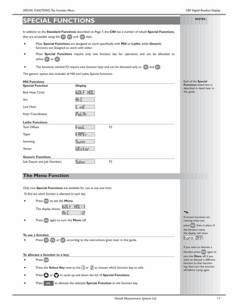
Mill FunctionsSpecial Function Display
Bolt Hole Circle
Arc
Line Hole
Polar Coordinates
Lathe Functions
Tool Offsets F2
Taper
Summing
Vector
Generic Functions
Sub Datum and Job Numbers F2
Bolt Hole Circle
MILL FUNCTIONS
MILL FUNCTIONS, Bolt Hole Circle C80 Digital Readout Display
NOTES
This function is also knownas Pitch Circle Diameter(PCD).
If you make a mistake whileentering a number, pressing
will clear the entry one
character at a time.
After an entry has beencompleted by pressing
, pressing the
navigation keys and
will take you
backwards and forwardsone step at a time.
To turn the function off,finish making any entry,then press the function keyagain
Newall Measurement Systems Ltd18
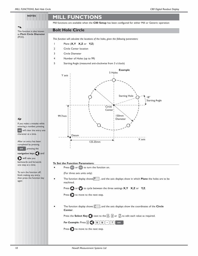
This function will calculate the locations of the holes, given the following parameters:
1 Plane (X,Y X,Z or Y,Z)
2 Circle Center location
3 Circle Diameter
4 Number of Holes (up to 99)
5 Starting Angle (measured anti-clockwise from 3 o’clock)
Example
To Set the Function Parameters:
• Press or to turn the function on.
(For three axis units only)
• The function display shows , and the axis displays show in which Plane the holes are to be machined.
Press or to cycle between the three settings X,Y X,Z or Y,Z.
Press to move to the next step.
• The function display shows , and the axis displays show the coordinates of the Circle Center.
Press the Select Key next to the , or , to edit each value as required.
For Example: Press .
Press to move to the next step.
Datum
99.7mm
125.25mm
150mmDiameter
CircleCenter
18°Starting Angle
Starting Hole
5 HolesY axis
X axis
Mill functions are available when the C80 Setup has been configured for either Mill or Generic operation
Bolt Hole Circle Continued
C80 Digital Readout DisplayMILL FUNCTIONS, Bolt Hole Circle
NOTES
The axis that is notinvolved in the Bolt HoleCircle function will read asnormal.
Newall Measurement Systems Ltd 19
• The function display shows , and the top axis display shows the Circle Diameter.
Enter a new value if required.
For Example: Press .
Press to move to the next step.
• The function display shows , and the top display shows the Number of Holes.
Enter a new value if required.
For Example: Press .
Press to move to the next step.
• The function display shows , and the top display shows the Starting Angle.
Enter a new value if required.
For Example: Press .
Press to finish setting the parameters.
• The function display shows .
To Machine the Holes:
The two axis displays for the selected plane now show the distance to the first hole.
• To position the tool ready for machining the hole, move the axes until both displays show zero.
The function display shows the number of the hole to be machined.
• Press the navigation keys or to move between the holes,
or enter the hole number.
For Example: Press to move directly to hole 4.
• When all holes have been machined, press or to turn the function off.
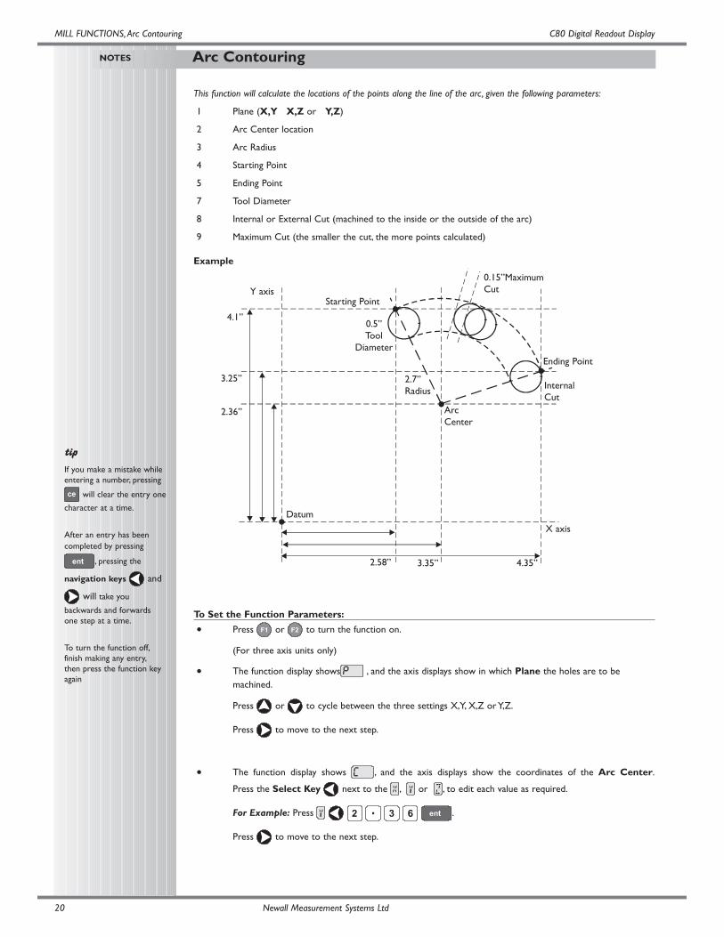
This function will calculate the locations of the points along the line of the arc, given the following parameters:
1 Plane (X,Y X,Z or Y,Z)
2 Arc Center location
3 Arc Radius
4 Starting Point
5 Ending Point
7 Tool Diameter
8 Internal or External Cut (machined to the inside or the outside of the arc)
9 Maximum Cut (the smaller the cut, the more points calculated)
Example
To Set the Function Parameters:
• Press or to turn the function on.
(For three axis units only)
• The function display shows , and the axis displays show in which Plane the holes are to be machined.
Press or to cycle between the three settings X,Y, X,Z or Y,Z.
Press to move to the next step.
• The function display shows , and the axis displays show the coordinates of the Arc Center.
Press the Select Key next to the , or , to edit each value as required.
For Example: Press .
Press to move to the next step.
Arc Contouring
MILL FUNCTIONS,Arc Contouring C80 Digital Readout Display
NOTES
If you make a mistake whileentering a number, pressing
will clear the entry one
character at a time.
After an entry has beencompleted by pressing
, pressing the
navigation keys and
will take you
backwards and forwardsone step at a time.
To turn the function off,finish making any entry,then press the function keyagain
Newall Measurement Systems Ltd20
Datum
4.1”
3.25”
2.36”
2.58” 3.35” 4.35”
2.7”Radius
ArcCenter
0.15”MaximumCut
Starting Point
0.5”Tool
Diameter
InternalCut
Ending Point
Y axis
X axis
C80 Digital Readout DisplayMILL FUNCTIONS,Arc Contouring
NOTES
If you enter a StartingPoint or Ending Pointthat is inconsistent with theCentre and Radiussettings, then the Centreand Radius settings willoverride the inconsistentsettings.
The axis that is notinvolved in the Arc functionwill read as normal.
The arc must be machinedprogressively. It is notpossible to jump betweenpoints on the arc.
Move away from the line ofthe Arc between points toavoid over cutting.
Newall Measurement Systems Ltd 21
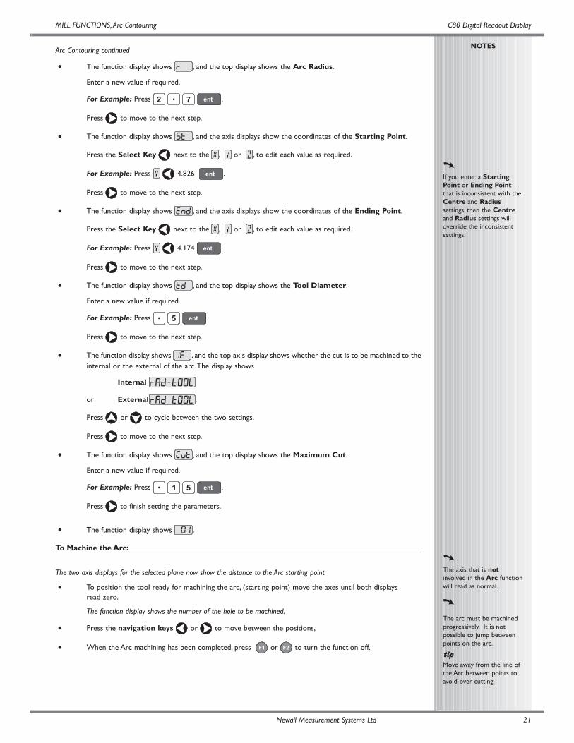
Arc Contouring continued
• The function display shows , and the top display shows the Arc Radius.
Enter a new value if required.
For Example: Press .
Press to move to the next step.
• The function display shows , and the axis displays show the coordinates of the Starting Point.
Press the Select Key next to the , or , to edit each value as required.
For Example: Press 4.826 .
Press to move to the next step.
• The function display shows , and the axis displays show the coordinates of the Ending Point.
Press the Select Key next to the , or , to edit each value as required.
For Example: Press 4.174 .
Press to move to the next step.
• The function display shows , and the top display shows the Tool Diameter.
Enter a new value if required.
For Example: Press .
Press to move to the next step.
• The function display shows , and the top axis display shows whether the cut is to be machined to theinternal or the external of the arc.The display shows
Internal
or External .
Press or to cycle between the two settings.
Press to move to the next step.
• The function display shows , and the top display shows the Maximum Cut.
Enter a new value if required.
For Example: Press .
Press to finish setting the parameters.
• The function display shows .
To Machine the Arc:
The two axis displays for the selected plane now show the distance to the Arc starting point
• To position the tool ready for machining the arc, (starting point) move the axes until both displays read zero.
The function display shows the number of the hole to be machined.
• Press the navigation keys or to move between the positions,
• When the Arc machining has been completed, press or to turn the function off.
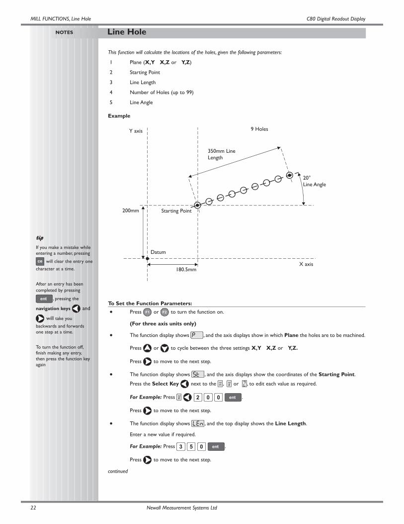
Line Hole
MILL FUNCTIONS, Line Hole C80 Digital Readout Display
NOTES
If you make a mistake whileentering a number, pressing
will clear the entry one
character at a time.
After an entry has beencompleted by pressing
, pressing the
navigation keys and
will take you
backwards and forwardsone step at a time.
To turn the function off,finish making any entry,then press the function keyagain
Newall Measurement Systems Ltd22
This function will calculate the locations of the holes, given the following parameters:
1 Plane (X,Y X,Z or Y,Z)
2 Starting Point
3 Line Length
4 Number of Holes (up to 99)
5 Line Angle
Example
To Set the Function Parameters:
• Press or to turn the function on.
(For three axis units only)
• The function display shows , and the axis displays show in which Plane the holes are to be machined.
Press or to cycle between the three settings X,Y X,Z or Y,Z.
Press to move to the next step.
• The function display shows , and the axis displays show the coordinates of the Starting Point.
Press the Select Key next to the , or , to edit each value as required.
For Example: Press .
Press to move to the next step.
• The function display shows , and the top display shows the Line Length.
Enter a new value if required.
For Example: Press .
Press to move to the next step.
continued
Datum
200mm
180.5mm
9 Holes
Starting Point
350mm LineLength
20°Line Angle
Y axis
X axis
Line Hole Continued
C80 Digital Readout DisplayMILL FUNCTIONS, Line Hole
NOTES
The axis that is notinvolved in the Line Holefunction will read as normal.
Newall Measurement Systems Ltd 23
• The function display shows , and the top display shows the Number of Holes.
Enter a new value if required.
For Example: Press .
Press to move to the next step.
• The function display shows , and the top display shows the Line Angle.
Enter a new value if required.
For Example:: Press .
Press to finish setting the parameters.
• The function display shows .
To Machine the Holes:
The two axis displays for the selected plane now show the distance to the first hole.
• To position the tool ready for machining the hole, move the axes until both displays read zero.
The function display shows the number of the hole to be machined.
• Press the navigation keys or to move between the holes, or enter the hole number.
For Example:: Press to move directly to hole 4.
• When all holes have been machined, press or to turn the function off.
Polar Coordinates
MILL FUNCTIONS, Polar Coordinates C80 Digital Readout Display
NOTES
The axis that is notinvolved in the PolarCoordinates function willdisplay as normal.
Newall Measurement Systems Ltd24
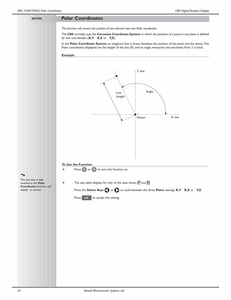
This function will convert the position of two selected axes into Polar coordinates.
The C80 normally uses the Cartesian Coordinate System, in which the position of a point in any plane is definedby two coordinates (X,Y X,Z or Y,Z).
In the Polar Coordinate System, an imaginary line is drawn between the position of the point and the datum.ThePolar coordinates displayed are the length of the line (P), and its angle, measured anti-clockwise from 3 o’clock.
Example
To Use the Function:
• Press or to turn the function on.
• The axis label displays for two of the axes shows and .
Press the Select Keys or to cycle between the three Plane settings X,Y X,Z or Y,Z.
Press to accept the setting.
Datum
LineLength
Angle
Y axis
X axis
C80 Digital Readout Display
Taper
LATHE FUNCTIONS
LATHE FUNCTIONS,Taper
NOTES
The conventional way to setup a lathe is:
X Axis – cross travel
Z Axis – longitudinal travel
Z’ Axis – compound travel.
If the Machine Type is setto Generic, then the axeswill be labelled:
Axis 1 – X
Axis 2 – Y
Axis 3 – Z
It is recommended that youuse this function inIncremental Mode, as itinvolves changing the datum.
The axes that are notshowing the Taper anglewill display as normal.
Newall Measurement Systems Ltd 25
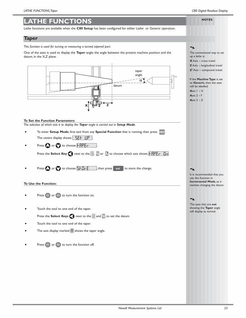
This function is used for turning or measuring a turned, tapered part.
One of the axes is used to display the Taper angle: the angle between the present machine position and thedatum, in the X,Z plane.
To Set the Function Parameters:The selection of which axis is to display the Taper angle is carried out in Setup Mode.
• To enter Setup Mode, first exit from any Special Function that is running, then press .
The centre display shows .
• Press or to choose .
Press the Select Key next to the , or to choose which axis shows .
• Press or to choose , then press to store the change.
To Use the Function:
• Press or to turn the function on.
• Touch the tool to one end of the taper.
Press the Select Keys next to the and , to set the datum.
• Touch the tool to one end of the taper.
• The axis display marked shows the taper angle.
• Press or to turn the function off.
X
αα
Z
taperangle
datum
Lathe functions are available when the C80 Setup has been configured for either Lathe or Generic operation.
Tool Offsets
LATHE FUNCTIONS,Tool Offsets C80 Digital Readout Display
NOTES
The conventional way to setup a lathe is:
X Axis – cross travel
Z Axis – longitudinal travel
Z’ Axis – compound travel.
If the Machine Type is setto Generic, then the axeswill be labelled:
Axis 1 – X
Axis 2 – Y
Axis 3 – Z
Set the C80 toIncremental Mode beforeusing Tool Offsets.
By doing this, you will beable to return the machineto its absolute datumafterwards, simply byswitching back to AbsoluteMode.
Newall Measurement Systems Ltd26
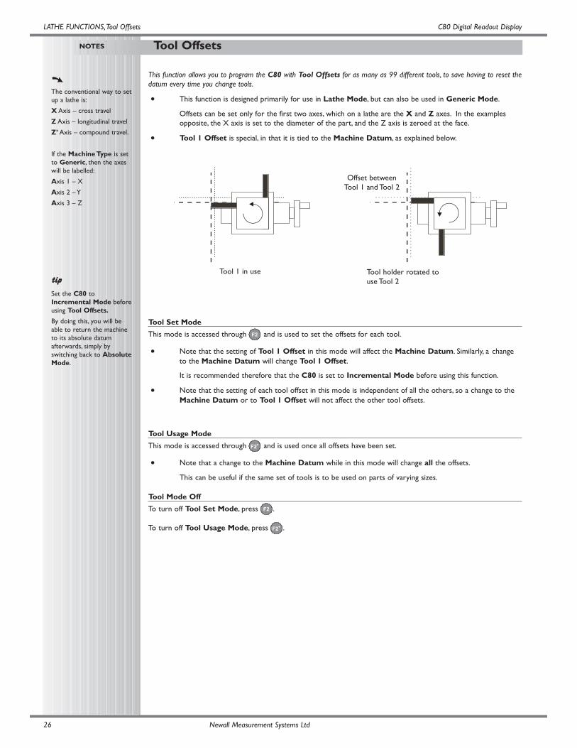
This function allows you to program the C80 with Tool Offsets for as many as 99 different tools, to save having to reset thedatum every time you change tools.
• This function is designed primarily for use in Lathe Mode, but can also be used in Generic Mode.
Offsets can be set only for the first two axes, which on a lathe are the X and Z axes. In the examples opposite, the X axis is set to the diameter of the part, and the Z axis is zeroed at the face.
• Tool 1 Offset is special, in that it is tied to the Machine Datum, as explained below.
Tool Set Mode
This mode is accessed through and is used to set the offsets for each tool.
• Note that the setting of Tool 1 Offset in this mode will affect the Machine Datum. Similarly, a change to the Machine Datum will change Tool 1 Offset.
It is recommended therefore that the C80 is set to Incremental Mode before using this function.
• Note that the setting of each tool offset in this mode is independent of all the others, so a change to the Machine Datum or to Tool 1 Offset will not affect the other tool offsets.
Tool Usage Mode
This mode is accessed through and is used once all offsets have been set.
• Note that a change to the Machine Datum while in this mode will change all the offsets.
This can be useful if the same set of tools is to be used on parts of varying sizes.
Tool Mode Off
To turn off Tool Set Mode, press .
To turn off Tool Usage Mode, press .
Tool 1 in use Tool holder rotated touse Tool 2
Offset betweenTool 1 and Tool 2
C80 Digital Readout DisplayLATHE FUNCTIONS,Tool Offsets
NOTES
If you make a mistake whileentering a number, pressing
will clear the entry one
character at a time.
To turn the function off,finish making any entry,then press the function keyagain .
Newall Measurement Systems Ltd 27
To Set the Tool Offsets:
• Press to turn on Tool Set Mode
• Press to select Datum Tool (Generally Tool No. 1)
The function display shows the tool number
1 Take a skim cut along the outside diameter of the part or touch the tool to the surface of the part (if cylindrical). Move the tool away from the part, taking care not to move the X axis. Measure the diameter of the part using a suitable gauge.
Press the Select Key next to the and enter the diameter of the part as measured.
For Example: Press to enter 20.5.
2 Take a facing cut or touch the end of the part with the tool. Move the tool away from the part, taking care not to move the Z axis.
Press the Select Key next to the and press to zero the axis.
The Tool Offsets Datum has now been established.
Press to move to the next tool.
3 Touch the tool to the surface of the part. Move the tool away from the part, taking care not to move the X axis.Measure the diameter of the part using a suitable gauge.
Press the Select Key next to the and enter the diameter of the part as measured
For Example: Press to enter 20.5.
4 Touch the end of the part with the tool. Move the tool away from the part, taking care not to movethe Z axis
Press the Select Key next to the and press to zero the axis.
Repeat Steps 3 and 4 for each tool to be set.
Press to turn off Tool Set Mode.
To Use the Tool Offsets:
• Press to turn on Tool Usage Mode.
• Press or to select the tool.
The function display shows the tool number , etc, to .
• Press to turn off Tool Usage Mode.
To Edit the Tool Offsets for Worn or Replacement Tools:
• Press to turn on Tool Usage Mode.
• Press or to select a known good tool.
• Set the axis datum as described in Steps 1 and 2 above.All offsets are now aligned with the correct Machine
Datum.
• Press to turn off Tool Usage Mode
• Press to turn on Tool Set Mode.
• Set the offsets for each tool as described in Steps 3 and 4 above.
• Press to turn off Tool Set Mode.
Summing
LATHE FUNCTIONS, Summing C80 Digital Readout Display
NOTES
The conventional way to setup a lathe is:
X Axis – cross travel
Z Axis – longitudinal travel
Z’ Axis – compound travel.
If the Machine Type is setto Generic, then the axeswill be labelled:
Axis 1 – X
Axis 2 – Y
Axis 3 – Z
The direction of Z’may have to be
changed in Setup to ensurethat the axes sum and notsubtract.
Newall Measurement Systems Ltd28
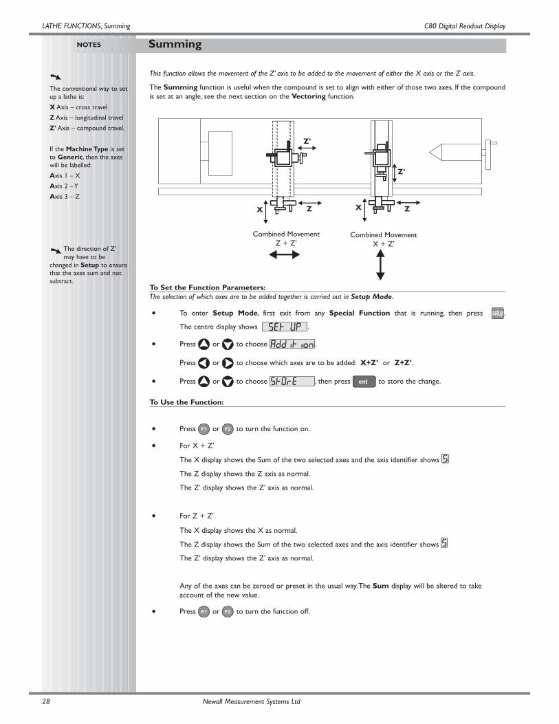
This function allows the movement of the Z’ axis to be added to the movement of either the X axis or the Z axis.
The Summing function is useful when the compound is set to align with either of those two axes. If the compoundis set at an angle, see the next section on the Vectoring function.
To Set the Function Parameters:The selection of which axes are to be added together is carried out in Setup Mode.
• To enter Setup Mode, first exit from any Special Function that is running, then press .
The centre display shows .
• Press or to choose .
Press or to choose which axes are to be added: X+Z’ or Z+Z’.
• Press or to choose , then press to store the change.
To Use the Function:
• Press or to turn the function on.
• For X + Z’
The X display shows the Sum of the two selected axes and the axis identifier shows
The Z display shows the Z axis as normal.
The Z’ display shows the Z’ axis as normal.
• For Z + Z’
The X display shows the X as normal.
The Z display shows the Sum of the two selected axes and the axis identifier shows
The Z’ display shows the Z’ axis as normal.
Any of the axes can be zeroed or preset in the usual way.The Sum display will be altered to take account of the new value.
• Press or to turn the function off.
X
Combined MovementZ + Z’
Combined MovementX + Z’
XZ Z
Z’
Z’
C80 Digital Readout Display
Vectoring
LATHE FUNCTIONS,Vectoring
NOTES
The conventional way to setup a lathe is:
X Axis – cross travel
Z Axis – longitudinal travel
Z’ Axis – compound travel.
If the Machine Type is setto Generic, then the axeswill be labelled:
Axis 1 – X
Axis 2 – Y
Axis 3 – Z
If you make a mistake whileentering a number, pressing
will clear the entry one
character at a time.
To turn the function off,finish making any entry,then press the function keyagain .
Newall Measurement Systems Ltd 29
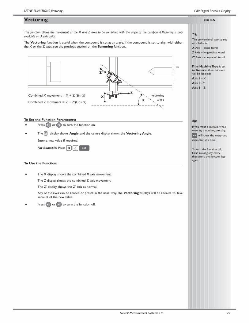
This function allows the movement of the X and Z axes to be combined with the angle of the compound.Vectoring is onlyavailable on 3 axis units.
The Vectoring function is useful when the compound is set at an angle. If the compound is set to align with eitherthe X or the Z axes, see the previous section on the Summing function.
To Set the Function Parameters:
• Press or to turn the function on.
• The display shows Angle, and the centre display shows the Vectoring Angle.
Enter a new value if required.
For Example: Press .
To Use the Function:
• The X display shows the combined X axis movement.
The Z display shows the combined Z axis movement.
The Z’ display shows the Z’ axis as normal.
Any of the axes can be zeroed or preset in the usual way.The Vectoring displays will be altered to takeaccount of the new value.
• Press or to turn the function off.
Combined X movement = X + Z’(Sin α)
Combined Z movement = Z + Z’(Cos α)X
αα
Zvectoring
angle
Z’
Sub-Datums and Jobs
GENERIC FUNCTIONS
GENERIC FUNCTIONS, Sub-Datums and Jobs C80 Digital Readout Display
NOTES
The conventional way to setup a lathe is:
X Axis – cross travel
Z Axis – longitudinal travel
Z’ Axis – compound travel.
If the Machine Type is setto Mill or Generic, thenthe axes will be labelled:
Axis 1 – X
Axis 2 – Y
Axis 3 – Z
Absolute Datum vs Sub-Datum
Note that all Sub-Datumsare relative to theAbsolute Datum, so if theAbsolute Datum ischanged, the Sub-Datumswill change accordingly.
The Sub-Datum functionalways works in AbsoluteMode. If the C80 is inIncremental Mode whenthe function is turned on,the C80 will switch toAbsolute Mode.
Other functions may beused in conjunction withSub-Datums, e.g. Bolt HoleCircle to produce arepeated pattern of holesabout different Sub-Datumpositions.
Newall Measurement Systems Ltd30
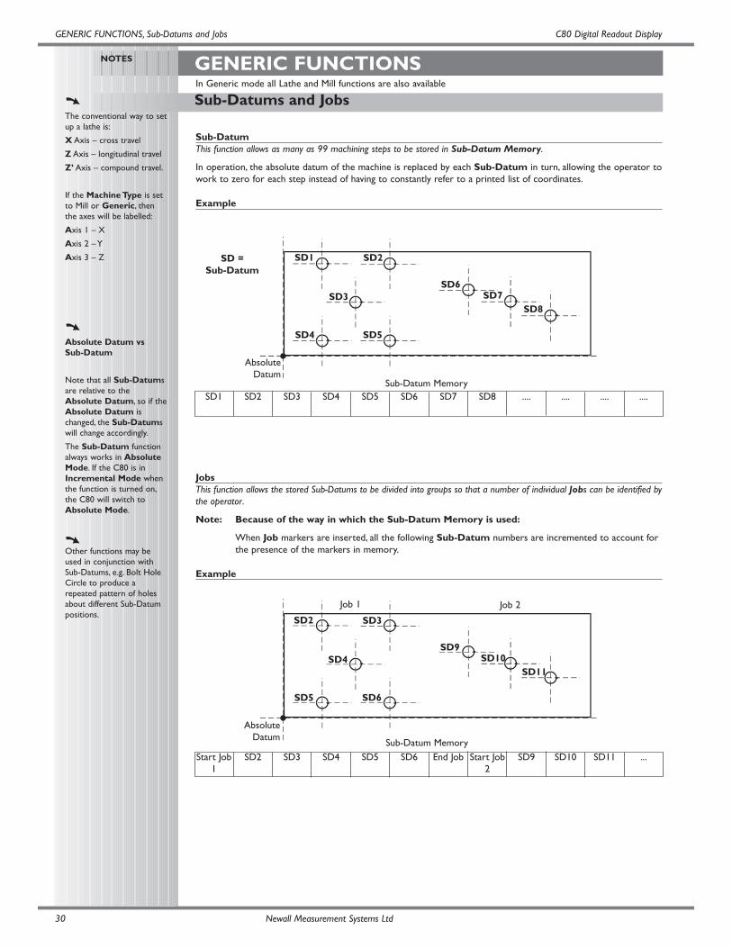
Sub-DatumThis function allows as many as 99 machining steps to be stored in Sub-Datum Memory.
In operation, the absolute datum of the machine is replaced by each Sub-Datum in turn, allowing the operator towork to zero for each step instead of having to constantly refer to a printed list of coordinates.
Example
JobsThis function allows the stored Sub-Datums to be divided into groups so that a number of individual Jobs can be identified bythe operator.
Note: Because of the way in which the Sub-Datum Memory is used:
When Job markers are inserted, all the following Sub-Datum numbers are incremented to account for the presence of the markers in memory.
Example
SD = Sub-Datum
AbsoluteDatum
Sub-Datum Memory
SD1 SD2
SD3
SD4 SD5
SD6SD7
SD8
AbsoluteDatum
SD2 SD3
SD4
SD5 SD6
SD9SD10
SD11
SD1 SD2 SD3 SD4 SD5 SD6 SD7 SD8 .... .... .... ....
Start Job1
SD2 SD3 SD4 SD5 SD6 End Job Start Job2
SD9 SD10 SD11 ...
Sub-Datum Memory
Job 1 Job 2
In Generic mode all Lathe and Mill functions are also available
C80 Digital Readout DisplayGENERIC FUNCTIONS, Sub-Datums
NOTES
Once the function is on, youcan go from one Sub-Datum to another, byeither of these twomethods:
1
Press , then
then enter the number ofthe Sub-Datum you wishto go to.
2Press the Select Keys
and to step from
one Sub-Datum to thenext.
If you make a mistake whileentering a number, pressing
will clear the entry one
character at a time.
To turn this function off,finish making any entry,
then press .
Newall Measurement Systems Ltd 31
To Turn the Function On and Off:
• Press to turn the function on.
The display shows
• Press the Select Key next to the .
The display changes to .
• Enter the number of the Sub-Datum you wish to go to.
For Example: Press to go to Sub-Datum 1.
• The function display shows the Sub-Datum number , upto
• Step from one Sub-Datum to the next by pressing the Select Key and .
• Press to turn the function off.
To Set a Sub Datum:
• Go to the Sub-Datum that is to be set, then use either of these two methods:
Teach Method;
• Move the machine to the position to be stored as the Sub-Datum.
Press .All displays show .
• The Sub-Datum is now set.
or
Preset Method;
You do not need to move the machine.
• Press , then the Select Key next to the first axis to be set.
• Enter the position of the Sub-Datum relative to the absolute datum, then press .
For Example: Press to enter the Sub-Datum position 99.7 into the
Y axis.
The display will show the distance from the current machine position to the Sub-Datum.
• Set any other axes that need to be set.
To Insert a Sub-Datum:
• Go to the point where the new Sub-Datum is to be inserted.
• Press .
The display shows .
• Press the Select Key next to the .
Note: Pressing any other key will cancel the operation.
All the following Sub-Datum numbers are incremented by one after a short time delay, and the display shows the current machine position.
• Set the new Sub-Datum as described above.
To Delete a Sub-Datum:• Go to the Sub-Datum that is to be deleted.
• Press .
The display shows .
• Press the Select Key next to the .
Note: Pressing any other key will cancel the operation.
All the following Sub-Datum numbers are decremented by one, after a short time delay, and the display shows the next Sub Datum.
GENERIC FUNCTIONS, Jobs C80 Digital Readout Display
NOTES
Once the function is on, youcan go from one Sub-Datum to another, byeither of these twomethods:
1
Press , then
then enter the number ofthe Sub-Datum you wishto go to.
2Press the Select Keys
and to step from
one Sub-Datum to thenext.
If you make a mistake whileentering a number, pressing
will clear the entry one
character at a time.
To turn this function off,finish making any entry,
then press .
Newall Measurement Systems Ltd32
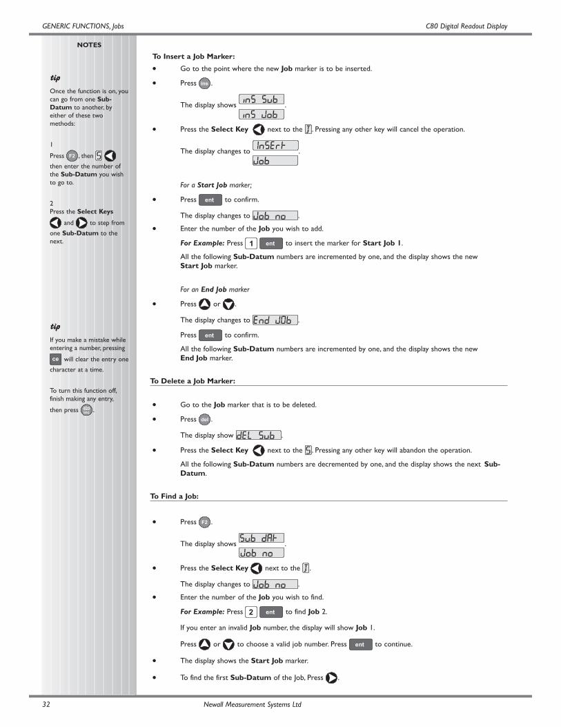
To Insert a Job Marker:
• Go to the point where the new Job marker is to be inserted.
• Press .
The display shows .
• Press the Select Key next to the . Pressing any other key will cancel the operation.
The display changes to .
For a Start Job marker;
• Press to confirm.
The display changes to .
• Enter the number of the Job you wish to add.
For Example: Press to insert the marker for Start Job 1.
All the following Sub-Datum numbers are incremented by one, and the display shows the new Start Job marker.
For an End Job marker
• Press or .
The display changes to .
Press to confirm.
All the following Sub-Datum numbers are incremented by one, and the display shows the new End Job marker.
To Delete a Job Marker:
• Go to the Job marker that is to be deleted.
• Press .
The display show .
• Press the Select Key next to the . Pressing any other key will abandon the operation.
All the following Sub-Datum numbers are decremented by one, and the display shows the next Sub-Datum.
To Find a Job:
• Press .
The display shows .
• Press the Select Key next to the .
The display changes to .
• Enter the number of the Job you wish to find.
For Example: Press to find Job 2.
If you enter an invalid Job number, the display will show Job 1.
Press or to choose a valid job number. Press to continue.
• The display shows the Start Job marker.
• To find the first Sub-Datum of the Job, Press .
C80 Digital Readout Display
CLEANING
TROUBLESHOOTING
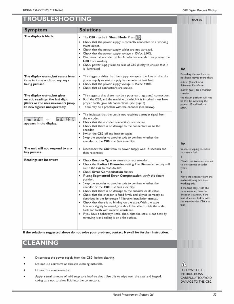
The display is blank.
The display works, but resets fromtime to time without any keysbeing pressed.
The display works, but giveserratic readings, the last digitjitters or the measurements jumpto new figures unexpectedly.
or appears in the display.
The unit will not respond to anykey presses.
Readings are incorrect
• The C80 may be in Sleep Mode. Press .
• Check that the power supply is correctly connected to a workingmains outlet.
• Check that the power supply cables are not damaged.• Check that the power supply voltage is 15Vdc ±10%.• Disconnect all encoder cables.A defective encoder can prevent the
C80 from working.• Check power supply lead on rear of C80 display to ensure that it
is illuminated
• This suggests either that the supply voltage is too low, or that thepower supply or mains supply has an intermittent fault.
• Check that the power supply voltage is 15Vdc ±10%.• Check that all connections are secure.
• This suggests that there may be a poor earth (ground) connection.• Both the C80, and the machine on which it is installed, must have
proper earth (ground) connections. (see page 3)• There may be a problem with the encoder (see below).
• This indicates that the unit is not receiving a proper signal fromthe encoder.
• Check that the encoder connections are secure.• Check that there is no damage to the connectors or to the
encoder.• Switch the C80 off and back on again.• Swap the encoder to another axis to confirm whether the
encoder or the C80 is at fault (see tip).
• Disconnect the C80 from its power supply, wait 15 seconds andthen reconnect.
• Check Encoder Type to ensure correct selection.• Check the Radius / Diameter setting.The Diameter setting will
cause the axis to read double.• Check Error Compensation factors.• If using Segmented Error Compensation, verify the datum
position.• Swap the encoder to another axis to confirm whether the
encoder or the C80 is at fault (see tip).• Check that there is no damage to the encoder or its cable.• Check that the encoder is fixed firmly and aligned correctly, as
described in the Spherosyn / Microsyn Installation manual.• Check that there is no binding on the scale.With the scale
brackets slightly loosened, you should be able to slide the scaleback and forth with minimal resistance.
• If you have a Spherosyn scale, check that the scale is not bent, byremoving it and rolling it on a flat surface.
SolutionsSymptom
NOTES
Providing the machine hasnot been moved more than:
6.3mm (0.25”) for aSpherosyn Encoder or
2.5mm (0.1”) for a MicrosynEncoder
the datum position will notbe lost by switching thepower off and back onagain.
When swapping encodersto trace a fault:
1
Check that two axes are setto the correct encodertypes.
2
Move the encoder from themalfunctioning axis to aworking axis.
If the fault stays with thesame encoder, then theencoder is at fault. If thefault does not follow withthe encoder the C80 is atfault
FOLLOW THESEINSTRUCTIONSCAREFULLY TO AVOIDDAMAGE TO THE C80.
Newall Measurement Systems Ltd 33
TROUBLESHOOTING, CLEANING
If the solutions suggested above do not solve your problem, contact Newall for further instruction.
• Disconnect the power supply from the C80 before cleaning.
• Do not use corrosive or abrasive cleaning materials.
• Do not use compressed air.
• Apply a small amount of mild soap to a lint-free cloth. Use this to wipe over the case and keypad,taking care not to allow fluid into the connectors.

023-80500 /01 January 2006
HEAD OFFICENewall Measurement Systems Ltd.
Technology Gateway, Cornwall RoadSouth Wigston
Leicester LE18 4XHUnited Kingdom
Telephone: +44 (0)116 264 2730Facsimile: +44 (0)116 264 2731
Email: [email protected]: www.newall.co.uk
Newall Electronics, Inc.1778 Dividend DriveColumbus, OH 43228
Telephone: +1 614 771 0213Toll Free: 800.229.4376
Facsimile: +1 614 771 0219Email: [email protected]: www.newall.com


![;$H16108;7,6$D0,:08/$]$C80 1 1 0$](https://img.pdfslide.net/doc/110x75/616efb564e150256b87eda07/h1610876d008c80-1-1-0.jpg)