Embed Size (px)
Citation preview
BAL C9302 PFB EN 1.21
Operating instructions
C9302-K0 Control computer for XC-Boards® with Profibus DP interface
2 BAL C9302 PFB EN 1.21
GERMANY FRANCE Siebert Industrieelektronik GmbH Siebert France Sarl Siebertstrasse, D-66571 Eppelborn 33 rue Poincaré, BP 90 334, F-57203 Sarreguemines Cédex Phone +49 (0)6806 980-0, Fax +49 (0)6806 980-999 Phone +33 (0)3 87 98 63 68, Fax +33 (0)3 87 98 63 94 www.siebert.de, [email protected] www.siebert.fr, [email protected] AUSTRIA NETHERLANDS Siebert Österreich GmbH Siebert Nederland B.V. Mooslackengasse 17. A-1190 Wien Korenmaat 12b, NL-9405 TJ Assen Phone +43 (0)1 890 63 86-0, Fax +43 (0)14 890 63 86-99 Phone +31 (0)592-305868, Fax +31 (0)592-301736 www.siebert-oesterreich.at, [email protected] www.siebert-nederland.nl, [email protected] SWITZERLAND Siebert AG Bützbergstrasse 2, Postfach 91, CH-4912 Aarwangen Phone +41 (0)62 922 18 70, Fax +41 (0)62 922 33 37 © Siebert Industrieelektronik GmbH www.siebert.ch, [email protected] This operation manual has been prepared with the utmost care. However, we do not accept any liability for possible errors. We always appreciate your suggestions for improvement, corrections, comments and proposals. Please contact us: [email protected]
Siebert®, LRD® and XC-Board® are registered trademarks of Siebert Industrieelektronik GmbH. All other product names mentioned herein may be the trademarks or registered trademarks of their respective owners.
We reserve the right to make alternations to the technical data and delivery options without notice. – All rights reserved, including the rights of translation. No part of this document may in any form or by any means (print, photocopy, microfilm or any other process) be reproduced or by using electronic systems be processed, copied, or distributed without our written permission.
BAL C9302 PFB EN 1.21 3
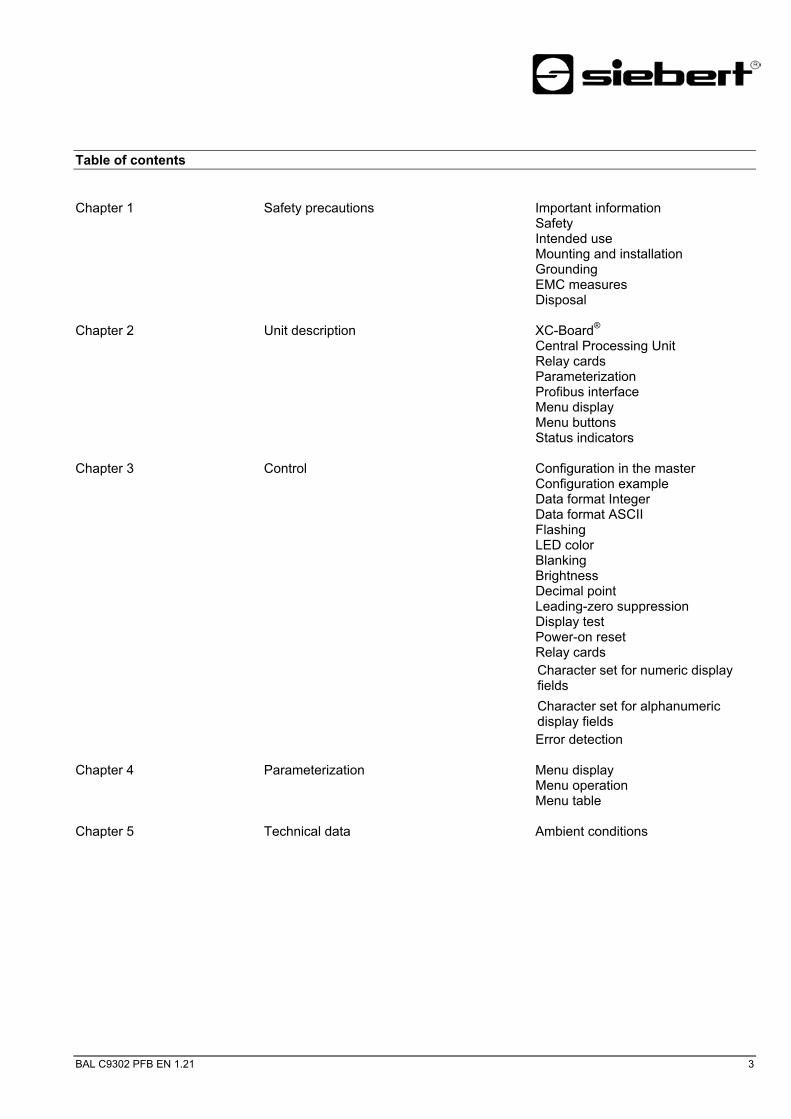
Table of contents Chapter 1 Safety precautions Important information
Safety Intended use Mounting and installation Grounding EMC measures Disposal
Chapter 2 Unit description XC-Board® Central Processing Unit Relay cards Parameterization Profibus interface Menu display Menu buttons Status indicators
Chapter 3 Control Configuration in the master Configuration example Data format Integer Data format ASCII Flashing LED color Blanking Brightness Decimal point Leading-zero suppression Display test Power-on reset Relay cards Character set for numeric display fields Character set for alphanumeric display fields Error detection
Chapter 4 Parameterization Menu display Menu operation Menu table
Chapter 5 Technical data Ambient conditions

4 BAL C9302 PFB EN 1.21

BAL C9302 PFB EN 1.21 5
Chapter 1 Safety precautions
Important information Read these operating instructions before starting the unit. They provide you with important information on the use, safety and maintenance of the units. This helps you to protect yourself and prevent damage to the unit.
Information intended to help you to avoid death, bodily harm or considerable damage to property are highlighted by the warning triangle shown here; it is imperative that this information be properly heeded.
The operating instructions are intended for trained professional electricians familiar with the safety standards of electrical technology and industrial electronics.
Store these operating instructions in an appropriate place.
The manufacturer is not liable if the information in these operating instructions are not complied with.
Safety Components inside the units are energized with electricity during operation. For this reason, mounting and maintenance work may only be performed by professionally-trained personnel while observing the corresponding safety regulations.
The repair and replacement of components and modules may only be carried out by the manufacturer for safety reasons and due to the required compliance with the documented unit properties.
The units do not have a power switch. They are operative as soon as the operating voltage is applied.
Intended use The units are intended for use in industrial environments. They may only beoperated within the limit values stipulated by the technical data.
When configuring, installing, maintaining and testing the units, the safety and accident-prevention regulations relevant to use in each individual case must be complied with.
Trouble-free, safe operation of the units requires proper transport, storage, installation, mounting and careful operation and maintenance of the units.
Mounting and installation The attachment options for the units were conceived in such a way as to ensure safe, reliable mounting.
The user must ensure that the attachment hardware, the unit carrier and the anchoring at the unit carrier are sufficient to securely support the unit under the given surrounding conditions.
The units are to be mounted in such a way that they can be opened up while mounted. Sufficient space for the cables must be available in the unit near the cable infeed.
Sufficient space is to be kept clear around the units to ensure air circulation and to prevent the build-up of heat resulting from use. The relevant information must be heeded in the case of units ventilated by other means.
When the housing fasteners are opened, the front frame of the housing hinges out upward or downward (depending on the unit version) automatically.

6 BAL C9302 PFB EN 1.21
Grounding All devices are equipped with a metal housing. They comply with safety class I and require a protective earth connection. The connecting cable for the operating voltage must contain a protective earth wire of a sufficient cross section (DIN VDE 0106 part 1, DIN VDE 0411 part 1).
EMC measures The devices comply with the EU Directive 89/336/EEC (EMC Directive) and provide the required interference immunity. Observe the following when connecting the operating voltage and data cables:
Use shielded data cables.
The data and operating voltage cables must be laid separately. They may not be laid together with heavy-current cables or other interference-producing cables.
The cable thickness must be properly assessed (DIN VDE 0100 Part 540).
The cable lengths inside the units are to be kept as short as possible to prevent interference. This applies especially to unshielded operating voltage cables. Shielded cables are also to be kept short due to any interference which might be emitted by the shielding.
Neither excessively long cables nor cable loops may be placed inside the units.
The connection of the cable shielding to the functional ground (PE) must be as short and low-impedance as possible. It should be made directly to the mounting plate over a large area with a conductive clip:
control
conductive clamp
mouting plate
data line terminals
bare metal surface
The cable shielding is to be connected at both cable ends. If equipotential
bonding currents are expected due to the cable arrangement, electrical isolation is to be performed on one side. In this case, capacitive connection (approx. 0.1µF/600 V AC) of the shielding on the isolated side must occur.
Disposal Units or unit parts which are no longer needed are to be disposed of in accordance
with the regulations in effect in your country.

BAL C9302 PFB EN 1.21 7
Chapter 2 Unit description
XC-Board® The control computer C9302-K0 serves for the activation of numeric or alphanumeric display fields in XC-Boards® via a Profibus-DP interface.
The following picture shows an example for an XC-Board® with four display fields:
The electrical structure of the XC-Boards® is documented in the included logic diagram. The following picture shows the general structure of the XC-Boards®:
The control computer takes over the conversion from binary format to decimal format in all display fields.
In the master, each display field is defined as an individual module.
Menu display
Address
Hi Lo
9
8
01
2
65
4
7 3
2
19
8
0
465
37Profibusinterface
DATABUSPWR
Status LEDs
Menu buttons
Central Processing Unit

8 BAL C9302 PFB EN 1.21
Relay cards Optionally, up to two relay cards with 8 relays each (type C9210) can be connected to the control computer, for example, for activating optical and acoustic signal transmitters.
The following picture shows the control computer with two relay cards:
Menu displayProfibus Interface
DATABUSPWR
Status LEDs
Menu buttons
Address
Hi Lo
90
1
65
4
190
465
I/O-Board 1I/O-Board 2
Parameterization The parameterization of the unit is done by means of a menu in the menu display
(see chapter 3).
Bus errors may result in personal injury or material damage. Therefore it is to observe that activating the menu may cause a bus error.
Profibus interface The Profibus interface is located on the SUB-D socket of the control computer. It
has the following assignment:
Pin 1 2 3 4 5 6 7 8 9 Signal – – B – GND + 5V – A –
� The units are Profibus-DP slaves according EN 50 170.
The baud rate is automatically recognized. It can reach up to 12 Mbaud.
The GSD file "SIEB0B4C.GSD" on disc is included in the delivery.
The control unit is defined as 'C9330 Control unit for XC-Boards' in the hardware configuration.
The address is set by means of the rotary code switches of the control computers (00...99).
In the case of a bus error, minus signs appear in the display.
Menu display The menu display represents a menu for unit parameterization (see chapter 3).
In normal operation, On nE is shown in the menu display.
Menu buttons The menu can be operated by means of the menu buttons (see chapter 3).
Status indicators The status indicators (LED) of the central processing unit have the following function:
PWR The Profibus interface is supplied with power. BUS The unit is parameterized and identified as a Profibus user. DATA The information to be represented is updated (short light-up).
BAL C9302 PFB EN 1.21 9
Chapter 3 Control
Bus errors may result in personal injury or material damage. Therefore it is to observe that activating the menu may cause a bus error.
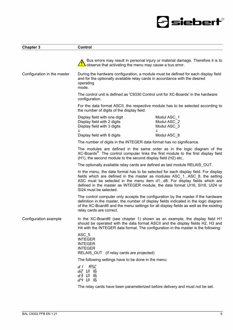
Configuration in the master During the hardware configuration, a module must be defined for each display field
and for the optionally available relay cards in accordance with the desired operating mode.
The control unit is defined as 'C9330 Control unit for XC-Boards' in the hardware configuration.
For the data format ASCII, the respective module has to be selected according to the number of digits of the display field:
Display field with one digit Modul ASC_1 Display field with 2 digits Modul ASC_2 Display field with 3 digits Modul ASC_3
Display field with 8 digits Modul ASC_8
The number of digits in the INTEGER data format has no significance.
The modules are defined in the same order as in the logic diagram of the XC-Boards®. The control computer links the first module to the first display field (H1), the second module to the second display field (H2) etc..
The optionally available relay cards are defined as last module RELAIS_OUT.
In the menu, the data format has to be selected for each display field. For display fields which are defined in the master as modules ASC_1...ASC_8, the setting ASC must be selected in the menu item d1...d8. For display fields which are defined in the master as INTEGER module, the data format UI16, SI16, UI24 or SI24 must be selected.
The control computer only accepts the configuration by the master if the hardware definition in the master, the number of display fields indicated in the logic diagram of the XC-Board® and the menu settings for all display fields as well as the existing relay cards are correct.
Configuration example In the XC-Board® (see chapter 1) shown as an example, the display field H1 should be operated with the data format ASCII and the display fields H2, H3 and H4 with the INTEGER data format. The configuration in the master is the following:
ASC_5 INTEGER INTEGER INTEGER RELAIS_OUT (if relay cards are projected)
The following settings have to be done in the menu:
D ASC d U d U d U
The relay cards have been parameterized before delivery and must not be set.

10 BAL C9302 PFB EN 1.21
INTEGER data format Data transmission is carried out with 4 bytes per display field.
Byte 0 contains the formatting of the device. The following bytes are displayed in INTEGER data format.
Byte 0 Byte 1 Byte 2 Byte 3 UI16/SI16 7 6 5 4 3 2 1 0 7 6 5 4 3 2 1 0 7 6 5 4 3 2 1 0 7 6 5 4 3 2 1 0
Formatting reserved MSB LSB Byte 0 Byte 1 Byte 2 Byte 3
UI24/SI24 7 6 5 4 3 2 1 0 7 6 5 4 3 2 1 0 7 6 5 4 3 2 1 0 7 6 5 4 3 2 1 0 Formatting MSB LSB : : : : : : : : : : : : : 0 0 0 No decimal point MSB: Most Significant Byte : : : : : 0 0 1 Decimal point digit C2 (highest value byte) : : : : : 0 1 0 Decimal point digit C3 LSB: Least Significant Byte : : : : : 0 1 1 Decimal point digit C4 (lowest value byte) : : : : : 1 0 0 Decimal point digit C5 : : : : : 1 0 1 Decimal point digit C6 : : : : : 1 1 0 Decimal point digit C7 : : : : : 1 1 1 Decimal point digit C8 : : : : : : : : : 0 Flashing of the display field off : : : : 1 Flashing of the display field on (only devices with LED display) : : : : : : : 0 Normal brightness of all display fields : : : 1 Reduced brightness of all display fields (only devices with LED display) : : : : : 0 Flashing of all display fields off : : 1 Flashing of all display fields on (only devices with LED display) : : 0 0 Retrace blanking of all display fields off 0 1 Retrace blanking of all display fields on 1 0 reserved
For devices with single colored LED displays or LRD® displays
: : 0 0 Red character color 0 1 Green character color 1 0 Orange character color
For devices with selectable LED colors
: : 1 1 Display test of all display fields
The formatting for the brightness, flashing of all display fields, retrace blanking and display test can be set in byte 0 of the display field H1. The bits in the other display fields should be set to 0 in byte 0.
Depending on the data format, the maximum value ranges are the following:
UI16 0…65535 SI16 -32768...32767 UI24 0…16777215 SI24 -8388608…8388607
If the transferred value exceeds the value range, then the following with appear on the display: o (upper range) or u (lower range).

BAL C9302 PFB EN 1.21 11
ASCII data format For the data transmission, the number of bytes depends on the number of digits of the display field. Byte 0 contains the formatting of the device. The following bytes are displayed in ASCII data format (C8…C1).
Byte 0 Byte 1 Display field with one digit Format. C1
Byte 0 Byte 1 Byte 2 Display field with 2 digits Format. C2 C1
Byte 0 Byte 1 Byte 2 Byte 3 Display field with 3 digits Format. C3 C2 C1
Byte 0 Byte 1 Byte 2 Byte 3 Byte 4 Display field with 4 digits Format. C4 C3 C2 C1
Byte 0 Byte 1 Byte 2 Byte 3 Byte 4 Byte 5 Display field with 5 digits Format. C5 C4 C3 C2 C1
Byte 0 Byte 1 Byte 2 Byte 3 Byte 4 Byte 5 Byte 6 Display field with 6 digits Format. C6 C5 C4 C3 C2 C1
Byte 0 Byte 1 Byte 2 Byte 3 Byte 4 Byte 5 Byte 6 Byte 7 Display field with 7 digits Format. C7 C6 C5 C4 C3 C2 C1
Byte 0 Byte 1 Byte 2 Byte 3 Byte 4 Byte 5 Byte 6 Byte 7 Byte 8 Display field with 8 digits Format. C8 C7 C6 C5 C4 C3 C2 C1
Byte 0 7 6 5 4 3 2 1 0 : : : : : : : : : : : : : 0 0 0 No decimal point : : : : : 0 0 1 Decimal point digit C2 : : : : : 0 1 0 Decimal point digit C3 : : : : : 0 1 1 Decimal point digit C4 : : : : : 1 0 0 Decimal point digit C5 : : : : : 1 0 1 Decimal point digit C6 : : : : : 1 1 0 Decimal point digit C7 : : : : : 1 1 1 Decimal point digit C8 : : : : : : : : : 0 Flashing of the display field off : : : : 1 Flashing of the display field on (only devices with LED display) : : : : : : : 0 Normal brightness of all display fields : : : 1 Reduced brightness of all display fields (only devices with LED display) : : : : : 0 Flashing of all display fields off : : 1 Flashing of all display fields on (only devices with LED display) : : 0 0 Retrace blanking of all display fields off 0 1 Retrace blanking of all display fields on 1 0 reserved
For devices with single colored LED displays or LRD® displays
: : 0 0 Red character color 0 1 Green character color 1 0 Orange character color
For devices with selectable LED colors
: : 1 1 Display test of all display fields
The formatting for the brightness, flashing of all display fields, retrace blanking and display test can be set in byte 0 of the display field H1. The bits in the other display fields should be set to 0 in byte 0.

12 BAL C9302 PFB EN 1.21
If in byte 0 bit 3 is set, the respective display field flashes.
If in byte 0 of the display field H1 bit 5 is set, all display fields will flash. (priority over flashing of individual display fields).
For units provided with an LRD® display flashing is not possible.
LED color The LED color can be set in byte 0 bit 7 and bit 6. (only for displays that have selectable LED colors).
Blanking If in byte 0 of the display field H1 bit 6 is set, all display fields are blank (priority over flashing). This is not possible for displays with selectable LED colors.
Brightness If in byte 0 of the display field H1 bit 4 is set, the brightness of all display fields will be reduced. (not possible for LRD® displays).
Decimal point In the menu items A1...A8, the decimal point can be set for each display (for numeric display fields only).
The decimal point can also be activated by setting bits 2…0 in byte 0. Setting 0 (no decimal point) should be chosen in the appropriate menu point (A1…A8).
If a decimal point has been set in the menu points A1…A8, this decimal point will have priority.
Units with a LRD® display have no decimal points.
Leading zero suppression In menu item C1…C8 you can set if leading zeros are to be displayed or suppressed (for numeric display fields only). If leading zeros should be suppressed for units with LRD® display and fixed decimal point (e.g. self-adhesive foil), the corresponding position must be set in menu item A1…A8.
Display test In menu item F, you can set whether a short-time display test is automatically carried out in all display fields after power-on.
The display test can be activated by setting bits 7 and 6 in byte 0 of the display field.
The display test has priority over flashing and blanking.
Power-on reset After power-on, minus signs are displayed to signalize that the unit is ready for operation. If a display test has been preselected in menu item F, it will run beforehand.

BAL C9302 PFB EN 1.21 13
Relay cards The optionally available relay cards are defined in the last module RELAIS_OUT with 2 byte regardless of how many relays have been implemented.
Byte 0 Byte 1 RELAIS_OUT 7 6 5 4 3 2 1 0 7 6 5 4 3 2 1 0
: : : : : : : : : : : : : : : : : : : : : : : : : : : : : : : 0 Relay 1 on relay card 1 off : : : : : : : : : : : : : : : 1 Relay 1 on relay card 1 on : : : : : : : : : : : : : : : : : : : : : : : : : : : : : 0 Relay 2 on relay card 1 off : : : : : : : : : : : : : : 1 Relay 2 on relay card 1 on : : : : : : : : : : : : : : : : : : : : : : : : : : : 0 Relay 3 on relay card 1 off : : : : : : : : : : : : : 1 Relay 3 on relay card 1 on : : : : : : : : : : : : : : : : : : : : : : : : : 0 Relay 4 on relay card 1 off : : : : : : : : : : : : 1 Relay 4 on relay card 1 on : : : : : : : : : : : : : : : : : : : : : : : 0 Relay 5 on relay card 1 off : : : : : : : : : : : 1 Relay 5 on relay card 1 on : : : : : : : : : : : : : : : : : : : : : 0 Relay 6 on relay card 1 off : : : : : : : : : : 1 Relay 6 on relay card 1 on : : : : : : : : : : : : : : : : : : : 0 Relay 7 on relay card 1 off : : : : : : : : : 1 Relay 7 on relay card 1 on : : : : : : : : : : : : : : : : : 0 Relay 8 on relay card 1 off : : : : : : : : 1 Relay 8 on relay card 1 on : : : : : : : : : : : : : : : : : : : : : : : : : : : : : : : 0 Relay 1 on relay card 2 off : : : : : : : 1 Relay 1 on relay card 2 on : : : : : : : : : : : : : 0 Relay 2 on relay card 2 off : : : : : : 1 Relay 2 on relay card 2 on : : : : : : : : : : : 0 Relay 3 on relay card 2 off : : : : : 1 Relay 3 on relay card 2 on : : : : : : : : : 0 Relay 4 on relay card 2 off : : : : 1 Relay 4 on relay card 2 on : : : : : : : 0 Relay 5 on relay card 2 off : : : 1 Relay 5 on relay card 2 on : : : : : 0 Relay 6 on relay card 2 off : : 1 Relay 6 on relay card 2 on : : : 0 Relay 7 on relay card 2 off : 1 Relay 7 on relay card 2 on : 0 Relay 8 on relay card 2 off 1 Relay 8 on relay card 2 on
14 BAL C9302 PFB EN 1.21
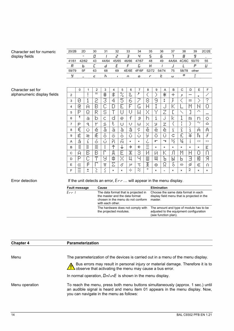
20/2B 2D 30 31 32 33 34 35 36 37 38 39 2C/2E
Character set for numeric display fields
41/61 42/62 43 44/64 45/65 46/66 47/67 48 49 4A/6A 4C/6C 50/70 55 A b C d E F G H I J L P U
59/79 5F 63 68 69 4E/6E 4F/6F 52/72 54/74 75 58/78 other
Y c h i n o r t u
0 1 2 3 4 5 6 7 8 9 A B C D E F
2 !
Character set for alphanumeric display fields
3 4 A B C D E F G H I J K L M N O 5 P Q R S T U V W X Y Z 6 a b c d e f g h i j k l m n o 7 p q r s t u v w x y z 8 U E A A A A E E I I A A 9 E Æ Æ O O O U U Y O U A A I O U N B │ C D E F
Error detection If the unit detects an error, Err… will appear in the menu display.
Fault message Cause Elimination Err The data format that is projected in
the master and the data format chosen in the menu do not conform with each other.
Choose the same data format in each display field menu that is projected in the master.
The hardware does not comply with the projected modules.
The amount and type of module has to be adjusted to the equipment configuration (see function plan).
Chapter 4 Parameterization
Menu The parameterization of the devices is carried out in a menu of the menu display.
Bus errors may result in personal injury or material damage. Therefore it is to observe that activating the menu may cause a bus error.
In normal operation, On nE is shown in the menu display.
Menu operation To reach the menu, press both menu buttons simultaneously (approx. 1 sec.) until an audible signal is heard and menu item 01 appears in the menu display. Now, you can navigate in the menu as follows:

BAL C9302 PFB EN 1.21 15
Next setting Shortly press key [ ] Page menu items forward Press key [ ] long Previous setting Double click on key [ ] Page menu items backward Double click on [ ] and keep it pressed
Next setting Shortly press key [ ] Page settings forward Press key [ ] long Previous setting Double click on key [ ] Page settings backward Double click on [ ] and keep it pressed
The menu ends in menu item U with the button [ ]. The settings made are either saved (set), not saved (escape) or the factory settings are reset, depending on the setting selected in menu item U.
Cancelling the menu without saving the settings made is possible by pressing both menu buttons longer (approx. 1 sec.) or will occur automatically if 60 seconds pass without a menu button being pressed.
Once the menu is closed, the unit behaves in the same manner as when the operating voltage was applied.
In the menu mode the character appears in all display fields. Control of the display is not possible in menu mode.
Menu table The menu items are displayed in the following menu table. The factory settings are marked with an *. Individual menu items or settings can be suppressed in another menu item, depending on the unit version or setting.
Menu item Settings Menu display d1 Unsigned Integer 16 Bit* d U
Data format display field H1 Signed Integer 16 Bit d S
Unsigned Integer 24 Bit d U
Signed Integer 24 Bit d S
ASCII d ASC
d2 Unsigned Integer 16 Bit* d U
Data format display field H2 Signed Integer 16 Bit d S
Unsigned Integer 24 Bit d U
Signed Integer 24 Bit d S
ASCII d ASC
d8 Unsigned Integer 16 Bit* d U
Data format display field H8 Signed Integer 16 Bit d S
Unsigned Integer 24 Bit d U
Signed Integer 24 Bit d S
ASCII d ASC

16 BAL C9302 PFB EN 1.21
Menu item Settings Menu display A1 No decimal point* A
Decimal point display field H1 Decimal point digit C1 A
Decimal point digit C2 A
Decimal point digit C8 A
A2 No decimal point* A
Decimal point display field H2 Decimal point digit C1 A
Decimal point digit C2 A
Decimal point digit C8 A
A8 No decimal point* A
Decimal point display field H8 Decimal point digit C1 A
Decimal point digit C2 A
Decimal point digit C8 A
C1 Leading zeros not displayed* C
Leading zeros display field H1 Leading zeros displayed C
C2 Leading zeros not displayed* C
Leading zeros display field H2 Leading zeros displayed C
C8 Leading zeros not displayed* C
Leading zeros display field H8 Leading zeros displayed C
F Display test No display test at power-on * F
Display test at power-on F
U Saving Saving parameters* (Set) U set
Not saving parameters (Escape) U ESC
Resetting to the default settings (Default) U deF
Chapter 5 Technical data
Ambient conditions Operating temperature 0…55 °C Storage temperature-30…85 °C Relative humidity max. 95 % (non-condensing)


![arXiv:1305.7375v2 [physics.comp-ph] 5 Jun 2013 · k0v t 2 cos k0 yv 2 cos k0 z v z t 2 1 3 sin k0 y v 2 sin k0 z v 2 =k sin k0 yv t cos k0 zv z t 2 cos k 0 xv x t 2 1 3 sin k 0 z](https://img.pdfslide.net/doc/110x75/5e6d6755adc6cb7d4075a992/arxiv13057375v2-5-jun-2013-k0v-t-2-cos-k0-yv-2-cos-k0-z-v-z-t-2-1-3-sin-k0.jpg)