Embed Size (px)
Citation preview

FN1050Rev 6.00
March 4, 2005
CA3240, CA3240ADual, 4.5MHz, BiMOS Operational Amplifier with MOSFET Input/Bipolar Output
DATASHEET
The CA3240A and CA3240 are dual versions of the popular CA3140 series integrated circuit operational amplifiers. They combine the advantages of MOS and bipolar transistors on the same monolithic chip. The gate-protected MOSFET (PMOS) input transistors provide high input impedance and a wide common-mode input voltage range (typically to 0.5V below the negative supply rail). The bipolar output transistors allow a wide output voltage swing and provide a high output current capability.
The CA3240A and CA3240 are compatible with the industry standard 1458 operational amplifiers in similar packages.
Functional Diagram
Features
• Dual Version of CA3140
• Internally Compensated
• MOSFET Input Stage
- Very High Input Impedance (ZIN) 1.5T (Typ)
- Very Low Input Current (II) 10pA (Typ) at 15V
- Wide Common-Mode Input Voltage Range (VICR): Can Be Swung 0.5V Below Negative Supply Voltage Rail
• Directly Replaces Industry Type 741 in Most Applications
• Pb-Free Available (RoHS Compliant)
Applications
• Ground Referenced Single Amplifiers in Automobile and Portable Instrumentation
• Sample and Hold Amplifiers
• Long Duration Timers/Multivibrators (Microseconds-Minutes-Hours)
• Photocurrent Instrumentation
PinoutCA3240, CA3240A (PDIP)
TOP VIEW
Ordering Information
PART NUMBERTEMP.
RANGE (oC) PACKAGEPKG.
DWG. #
CA3240AE -40 to 85 8 Ld PDIP E8.3
CA3240AEZ(See Note)
-40 to 85 8 Ld PDIP(Pb-free)
E8.3
CA3240E -40 to 85 8 Ld PDIP E8.3
CA3240EZ(See Note)
-40 to 85 8 Ld PDIP(Pb-free)
E8.3
Pb-free PDIPs can be used for through hole wave solder processing only. They are not intended for use in Reflow solder processing applications.
NOTE: Intersil Pb-free products employ special Pb-free material sets; molding compounds/die attach materials and 100% matte tin plate termination finish, which are RoHS compliant and compatible with both SnPb and Pb-free soldering operations. Intersil Pb-free products are MSL classified at Pb-free peak reflow temperatures that meet or exceed the Pb-free requirements of IPC/JEDEC J STD-020.
A 10,000
BIAS CIRCUITCURRENT SOURCES
AND REGULATOR
A 1
2mA 4mA
2mA1.6mA 2A200A200A
IN-OUT-
C1
12pF
V+
V-
+
-
A 10PUT
PUT
• Intrusion Alarm System • Active Filters
• Comparators • Function Generators
• Instrumentation Amplifiers • Power Supplies
OUTPUT (A)
INV.INPUT (A)
NON-INV.
1
2
3
4
8
7
6
5
V+
OUTPUT
INV.
NON-INV.INPUT (A)
V-
INPUT (B)
INPUT (B)
FN1050 Rev 6.00 Page 1 of 15March 4, 2005
CA3240, CA3240A
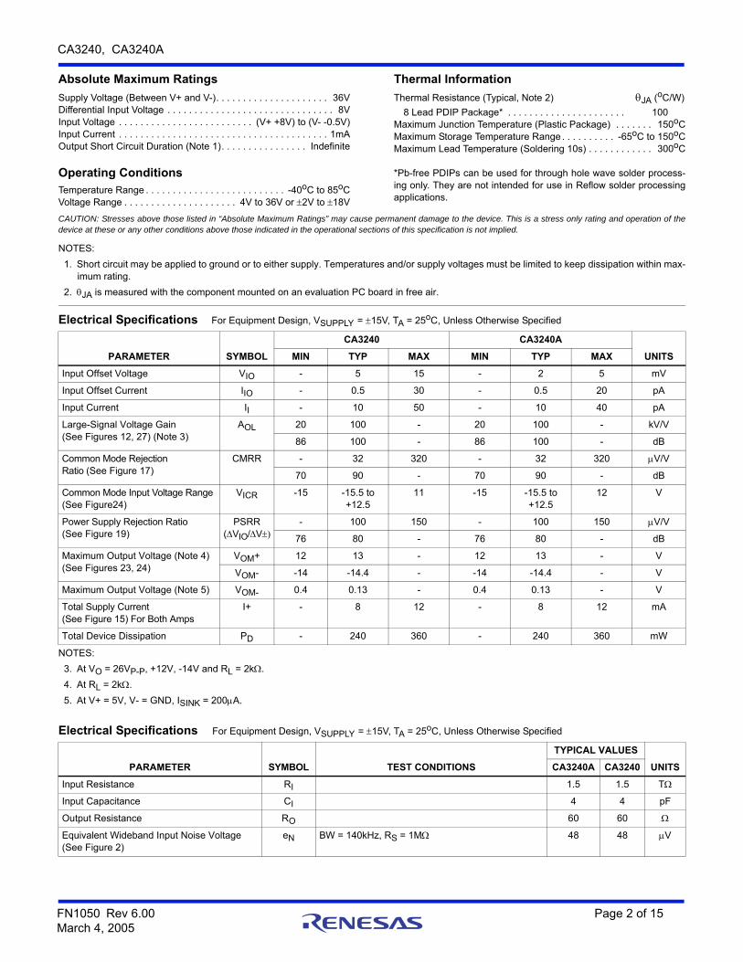
Absolute Maximum Ratings Thermal Information
Supply Voltage (Between V+ and V-). . . . . . . . . . . . . . . . . . . . . 36VDifferential Input Voltage . . . . . . . . . . . . . . . . . . . . . . . . . . . . . . . 8VInput Voltage . . . . . . . . . . . . . . . . . . . . . . . . . (V+ +8V) to (V- -0.5V)Input Current . . . . . . . . . . . . . . . . . . . . . . . . . . . . . . . . . . . . . . . 1mAOutput Short Circuit Duration (Note 1). . . . . . . . . . . . . . . . Indefinite
Operating ConditionsTemperature Range . . . . . . . . . . . . . . . . . . . . . . . . . . -40oC to 85oCVoltage Range . . . . . . . . . . . . . . . . . . . . . 4V to 36V or 2V to 18V
Thermal Resistance (Typical, Note 2) JA (oC/W)
8 Lead PDIP Package* . . . . . . . . . . . . . . . . . . . . . . 100Maximum Junction Temperature (Plastic Package) . . . . . . . 150oCMaximum Storage Temperature Range . . . . . . . . . . -65oC to 150oCMaximum Lead Temperature (Soldering 10s) . . . . . . . . . . . . 300oC
*Pb-free PDIPs can be used for through hole wave solder process-ing only. They are not intended for use in Reflow solder processingapplications.
CAUTION: Stresses above those listed in “Absolute Maximum Ratings” may cause permanent damage to the device. This is a stress only rating and operation of thedevice at these or any other conditions above those indicated in the operational sections of this specification is not implied.
NOTES:
1. Short circuit may be applied to ground or to either supply. Temperatures and/or supply voltages must be limited to keep dissipation within max-imum rating.
2. JA is measured with the component mounted on an evaluation PC board in free air.
Electrical Specifications For Equipment Design, VSUPPLY = 15V, TA = 25oC, Unless Otherwise Specified
PARAMETER SYMBOL
CA3240 CA3240A
UNITSMIN TYP MAX MIN TYP MAX
Input Offset Voltage VIO - 5 15 - 2 5 mV
Input Offset Current IIO - 0.5 30 - 0.5 20 pA
Input Current II - 10 50 - 10 40 pA
Large-Signal Voltage Gain(See Figures 12, 27) (Note 3)
AOL 20 100 - 20 100 - kV/V
86 100 - 86 100 - dB
Common Mode Rejection Ratio (See Figure 17)
CMRR - 32 320 - 32 320 V/V
70 90 - 70 90 - dB
Common Mode Input Voltage Range (See Figure24)
VICR -15 -15.5 to +12.5
11 -15 -15.5 to +12.5
12 V
Power Supply Rejection Ratio (See Figure 19)
PSRR(VIO/V
- 100 150 - 100 150 V/V
76 80 - 76 80 - dB
Maximum Output Voltage (Note 4)(See Figures 23, 24)
VOM+ 12 13 - 12 13 - V
VOM- -14 -14.4 - -14 -14.4 - V
Maximum Output Voltage (Note 5) VOM- 0.4 0.13 - 0.4 0.13 - V
Total Supply Current(See Figure 15) For Both Amps
I+ - 8 12 - 8 12 mA
Total Device Dissipation PD - 240 360 - 240 360 mW
NOTES:
3. At VO = 26VP-P, +12V, -14V and RL = 2k.
4. At RL = 2k.
5. At V+ = 5V, V- = GND, ISINK = 200A.
Electrical Specifications For Equipment Design, VSUPPLY = 15V, TA = 25oC, Unless Otherwise Specified
PARAMETER SYMBOL TEST CONDITIONS
TYPICAL VALUES
UNITSCA3240A CA3240
Input Resistance RI 1.5 1.5 T
Input Capacitance CI 4 4 pF
Output Resistance RO 60 60
Equivalent Wideband Input Noise Voltage (See Figure 2)
eN BW = 140kHz, RS = 1M 48 48 V
FN1050 Rev 6.00 Page 2 of 15March 4, 2005
CA3240, CA3240A
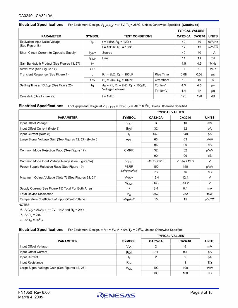
Equivalent Input Noise Voltage(See Figure 18)
eN f = 1kHz, RS = 100 40 40 nV/Hz
f = 10kHz, RS = 100 12 12 nV/Hz
Short-Circuit Current to Opposite Supply IOM+ Source 40 40 mA
IOM- Sink 11 11 mA
Gain Bandwidth Product (See Figures 13, 27) fT 4.5 4.5 MHz
Slew Rate (See Figure 14) SR 9 9 V/s
Transient Response (See Figure 1) tr RL = 2k, CL = 100pF Rise Time 0.08 0.08 s
OS RL = 2k, CL = 100pF Overshoot 10 10 %
Settling Time at 10VP-P (See Figure 25) tS AV = +1, RL = 2k, CL = 100pF, Voltage Follower
To 1mV 4.5 4.5 s
To 10mV 1.4 1.4 s
Crosstalk (See Figure 22) f = 1kHz 120 120 dB
Electrical Specifications For Equipment Design, VSUPPLY = 15V, TA = 25oC, Unless Otherwise Specified (Continued)
PARAMETER SYMBOL TEST CONDITIONS
TYPICAL VALUES
UNITSCA3240A CA3240
Electrical Specifications For Equipment Design, at VSUPPLY = 15V, TA = -40 to 85oC, Unless Otherwise Specified
PARAMETER SYMBOL
TYPICAL VALUES
UNITSCA3240A CA3240
Input Offset Voltage |VIO| 3 10 mV
Input Offset Current (Note 8) |IIO| 32 32 pA
Input Current (Note 8) II 640 640 pA
Large Signal Voltage Gain (See Figures 12, 27), (Note 6) AOL 63 63 kV/V
96 96 dB
Common Mode Rejection Ratio (See Figure 17) CMRR 32 32 V/V
90 90 dB
Common Mode Input Voltage Range (See Figure 24) VICR -15 to +12.3 -15 to +12.3 V
Power Supply Rejection Ratio (See Figure 19) PSRR(VIO/V)
150 150 V/V
76 76 dB
Maximum Output Voltage (Note 7) (See Figures 23, 24) VOM+ 12.4 12.4 V
VOM- -14.2 -14.2 V
Supply Current (See Figure 15) Total For Both Amps I+ 8.4 8.4 mA
Total Device Dissipation PD 252 252 mW
Temperature Coefficient of Input Offset Voltage VIO/T 15 15 V/oC
NOTES:
6. At VO = 26VP-P, +12V, -14V and RL = 2k.
7. At RL = 2k.
8. At TA = 85oC.
Electrical Specifications For Equipment Design, at V+ = 5V, V- = 0V, TA = 25oC, Unless Otherwise Specified
PARAMETER SYMBOL
TYPICAL VALUES
UNITSCA3240A CA3240
Input Offset Voltage |VIO| 2 5 mV
Input Offset Current |IIO| 0.1 0.1 pA
Input Current II 2 2 pA
Input Resistance RIN 1 1 T
Large Signal Voltage Gain (See Figures 12, 27) AOL 100 100 kV/V
100 100 dB
FN1050 Rev 6.00 Page 3 of 15March 4, 2005

CA3240, CA3240A
Common-Mode Rejection Ratio CMRR 32 32 V/V
90 90 dB
Common-Mode Input Voltage Range (See Figure 24) VICR -0.5 -0.5 V
2.6 2.6 V
Power Supply Rejection Ratio PSRR 31.6 31.6 V/V
90 90 dB
Maximum Output Voltage (See Figures 23, 24) VOM+ 3 3 V
VOM- 0.3 0.3 V
Maximum Output Current Source IOM+ 20 20 mA
Sink IOM- 1 1 mA
Slew Rate (See Figure14) SR 7 7 V/s
Gain Bandwidth Product (See Figure 13) fT 4.5 4.5 MHz
Supply Current (See Figure 15) I+ 4 4 mA
Device Dissipation PD 20 20 mW
Electrical Specifications For Equipment Design, at V+ = 5V, V- = 0V, TA = 25oC, Unless Otherwise Specified (Continued)
PARAMETER SYMBOL
TYPICAL VALUES
UNITSCA3240A CA3240
Test Circuits and Waveforms
FIGURE 1A. SMALL SIGNAL RESPONSE FIGURE 1B. LARGE SIGNAL RESPONSE
FIGURE 1C. TEST CIRCUIT
FIGURE 1. SPLIT-SUPPLY VOLTAGE FOLLOWER TEST CIRCUIT AND ASSOCIATED WAVEFORMS
50mV/Div., 200ns/Div.Top Trace: Input, Bottom Trace: Output
5V/Div., 1s/Div.Top Trace: Input, Bottom Trace: Output
2k
10k
CA3240
+15V
-15V
0.1F
0.1F
100pF
SIMULATEDLOAD
2k
0.05F
+
-
BW (-3dB) = 4.5MHzSR = 9V/s
FN1050 Rev 6.00 Page 4 of 15March 4, 2005

CA3240, CA3240A
Schematic Diagram (One Amplifier of Two)
FIGURE 2. TEST CIRCUIT AMPLIFIER (30dB GAIN) USED FOR WIDEBAND NOISE MEASUREMENT
Test Circuits and Waveforms (Continued)
RS
CA3240
+15V
-15V
0.01F
0.01F
+
-
BW (-3dB) = 140kHzTOTAL NOISE VOLTAGE
30.1k
1k
1M
(REFERRED TO INPUT) = 48V (TYP)
NOISEVOLTAGEOUTPUT
BIAS CIRCUIT INPUT STAGE SECOND STAGE OUTPUT STAGE DYNAMIC CURRENT SINKV+
OUTPUT
V-
INVERTINGINPUT
NON-INVERTINGINPUT +
-
R18K
Q1
D1
Q6
Q7
Q8
Q2
Q5 Q4
Q3
D2D3 D4
D5
Q9 Q10
R2500
R5500
R4500
R3500
Q11 Q12
Q13
C112pF
Q14
R650
R730
Q15Q16
R81K
R1120
Q17
R101K
R950
D7
D8
Q20
Q21
R1212K
R1420K
R1315K
D6
Q18
Q19
NOTES:
9. All resistance values are in ohms.
FN1050 Rev 6.00 Page 5 of 15March 4, 2005

CA3240, CA3240A
Application Information
Circuit Description
The schematic diagram details one amplifier section of the CA3240. It consists of a differential amplifier stage using PMOS transistors (Q9 and Q10) with gate-to-source protection against static discharge damage provided by zener diodes D3, D4, and D5. Constant current bias is applied to the differential amplifier from transistors Q2 and Q5 connected as a constant current source. This assures a high common-mode rejection ratio. The output of the differential amplifier is coupled to the base of gain stage transistor Q13 by means of an NPN current mirror that supplies the required differential-to-single-ended conversion.
The gain stage transistor Q13 has a high impedance active load (Q3 and Q4) to provide maximum open-loop gain. The collector of Q13 directly drives the base of the compound emitter-follower output stage. Pulldown for the output stage is provided by two independent circuits: (1) constant-current-connected transistors Q14 and Q15 and (2) dynamic current-sink transistor Q16 and its associated circuitry. The level of pulldown current is constant at about 1mA for Q15 and varies from 0 to 18mA for Q16 depending on the magnitude of the voltage between the output terminal and V+. The dynamic current sink becomes active whenever the output terminal is more negative than V+ by about 15V. When this condition exists, transistors Q21 and Q16 are turned on causing Q16 to sink current from the output terminal to V-. This current always flows when the output is in the linear region, either from the load resistor or from the emitter of Q18 if no load resistor is present. The purpose of this dynamic sink is to permit the output to go within 0.2V (VCE (sat)) of V- with a 2k load to ground. When the load is returned to V+, it may be necessary to supplement the 1mA of current from Q15 in order to turn on the dynamic current sink (Q16). This may be accomplished by placing a resistor (Approx. 2k) between the output and V-.
Output Circuit Considerations
Figure 23 shows output current-sinking capabilities of the CA3240 at various supply voltages. Output voltage swing to the negative supply rail permits this device to operate both power transistors and thyristors directly without the need for level-shifting circuitry usually associated with the 741 series of operational amplifiers.
Figure 3 shows some typical configurations. Note that a series resistor, RL, is used in both cases to limit the drive available to the driven device. Moreover, it is recommended that a series diode and shunt diode be used at the thyristor input to prevent large negative transient surges that can appear at the gate of thyristors, from damaging the integrated circuit.
Input Circuit Considerations
As indicated by the typical VICR, this device will accept inputs as low as 0.5V below V-. However, a series current-limiting resistor is recommended to limit the maximum input terminal current to less than 1mA to prevent damage to the input protection circuitry.
Moreover, some current-limiting resistance should be provided between the inverting input and the output when the CA3240 is used as a unity-gain voltage follower. This resistance prevents the possibility of extremely large input-signal transients from forcing a signal through the input-protection network and directly driving the internal constant-current source which could result in positive feedback via the output terminal. A 3.9k resistor is sufficient.
The typical input current is on the order of 10pA when the inputs are centered at nominal device dissipation. As the output supplies load current, device dissipation will increase, raising the chip temperature and resulting in increased input current. Figure 4 shows typical input-terminal current versus ambient temperature for the CA3240.
CA3240
RS
RLMT1
MT2
120VAC
LOAD
30V NO LOAD
CA3240
LOAD
RL
V+ +HV
FIGURE 3. METHODS OF UTILIZING THE VCE (SAT) SINKING CURRENT CAPABILITY OF THE CA3240 SERIES
FN1050 Rev 6.00 Page 6 of 15March 4, 2005

CA3240, CA3240A
It is well known that MOSFET devices can exhibit slight changes in characteristics (for example, small changes in input offset voltage) due to the application of large differential input voltages that are sustained over long periods at elevated temperatures.
Both applied voltage and temperature accelerate these changes. The process is reversible and offset voltage shifts of the opposite polarity reverse the offset. In typical linear applications, where the differential voltage is small and symmetrical, these incremental changes are of about the same magnitude as those encountered in an operational amplifier employing a bipolar transistor input stage.
Typical Applications
On/Off Touch Switch
The on/off touch switch shown in Figure 5 uses the CA3240E to sense small currents flowing between two contact points on a touch plate consisting of a PC board metallization “grid”. When the “on” plate is touched, current flows between the two halves of the grid causing a positive shift in the output voltage (Terminal 7) of the CA3240E. These positive transitions are fed into the CA3059, which is used as a latching circuit and zero-crossing TRIAC driver. When a positive pulse occurs at Terminal 7 of the CA3240E, the TRIAC is turned on and held on by the CA3059 and its associated positive feedback circuitry (51k resistor and 36k/42k voltage divider). When the positive pulse occurs at Terminal 1 (CA3240E), the TRIAC is turned off and held off in a similar manner. Note that power for the CA3240E is supplied by the CA3059 internal power supply.
The advantage of using the CA3240E in this circuit is that it can sense the small currents associated with skin conduction while allowing sufficiently high circuit impedance to provide protection against electrical shock.
Dual Level Detector (Window Comparator)
Figure 6 illustrates a simple dual liquid level detector using the CA3240E as the sensing amplifier. This circuit operates on the principle that most liquids contain enough ions in solution to sustain a small amount of current flow between two electrodes submersed in the liquid. The current, induced by an 0.5V potential applied between two halves of a PC board grid, is converted to a voltage level by the CA3240E in a circuit similar to that of the on/off touch switch shown in Figure 5. The changes in voltage for both the upper and lower level sensors are processed by the CA3140 to activate an LED whenever the liquid level is above the upper sensor or below the lower sensor.
Constant-Voltage/Constant-Current Power Supply
The constant-voltage/constant-current power supply shown in Figure 7 uses the CA3240E as a voltage-error and current-sensing amplifier. The CA3240E is ideal for this application because its input common-mode voltage range includes ground, allowing the supply to adjust from 20mV to 25V without requiring a negative supply voltage. Also, the ground reference capability of the CA3240E allows it to sense the voltage across the 1 current-sensing resistor in the negative output lead of the power supply. The CA3086 transistor array functions as a reference for both constant-voltage and constant-current limiting. The 2N6385 power Darlington is used as the pass element and may be required to dissipate as much as 40W. Figure 8 shows the transient response of the supply during a 100mA to 1A load transition.
Precision Differential Amplifier
Figure 9 shows the CA3240E in the classical precision differential amplifier circuit. The CA3240E is ideally suited for biomedical applications because of its extremely high input impedance. To insure patient safety, an extremely high electrode series resistance is required to limit any current that might result in patient discomfort in the event of a fault condition. In this case, 10M resistors have been used to limit the current to less than 2A without affecting the performance of the circuit. Figure 10 shows a typical electrocardiogram waveform obtained with this circuit.
VS =15V
TEMPERATURE (oC)
-60 -40 -20 0 20 40 60 80 100 120 140
100
10
INP
UT
CU
RR
EN
T (
pA
)
1K
10K
FIGURE 4. INPUT CURRENT vs TEMPERATURE
FN1050 Rev 6.00 Page 7 of 15March 4, 2005

CA3240, CA3240A
NOTE:
10. At 220V operation, TRIAC should be T2300D, RS = 18K, 5W.
FIGURE 5. ON/OFF TOUCH SWITCH
FIGURE 6. DUAL LEVEL DETECTER
7
1
2
3
5
65
13
9
10
2
4
8
711
8
4
120V/220VAC60Hz/50Hz
10K (2W)
RS (NOTE 10)
12KMT2
MT1G
40W120V LIGHT
T2300B (NOTE 12)
51K
COMMON
+
- 100F (16V)+6V SOURCE
1N914
1N914
42K
36K
+6V+6V
44M
44M
CA3059
CA3240
CA3240
+
-
+
-
+6V
1M
5.1M
1M
0.01F
0.01F 1M
“ON”
“OFF”1/2
1/2
6
5
3
2
8
4
+15V
12M
12M
+15V
8.2K
240K
100K
100K
1
7
7
+15V
CA3140
+
-
6
3
2
4
33K
100K
100K
160K
0.1F
(0.5V)HIGH
LEVEL
LOWLEVEL
0.1F
680
LED
LED ON WHENLIQUID OUTSIDEOF LIMITS
CA3240
+
-1/2
CA3240
+
-
1/2
FN1050 Rev 6.00 Page 8 of 15March 4, 2005

CA3240, CA3240A
FIGURE 7. CONSTANT-VOLTAGE/CONSTANT-CURRENT POWER SUPPLY
FIGURE 8. TRANSIENT RESPONSE
3
2
1
10
11
9
8
7
64
5
3
1
2
12
14
1
2
3
8
4
7
6
5
8
13
-
+
1/2CA3240E
2N6385
DARLINGTON
75
3K
2.7KVI = 30V
+- 2000F
50V
CA3086E
TRANSISTORARRAY
CHASSIS GROUND
2.2K
6.2K
1K
+-
5F16V
100K
100K
50K
100K
100
V+
V+
10K
+
-1/2CA3240E
1N914
0.056F
820 680K
100K 11W
180K
82K
+-
500F
IO
VO
VO RANGE = 20mV TO 25VLOAD REGULATION:
VOLTAGE <0.08%CURRENT <0.05%
OUTPUT HUM AND NOISE 150VRMS(10MHz BANDWIDTH)
SINE REGULATION 0.1%/VOIO RANGE = 10mA - 1.3A
Top Trace: Output Voltage;500mV/Div., 5s/Div.
Bottom Trace: Collector Of Load Switching TransistorLoad = 100mA to 1A; 5V/Div., 5s/Div.
FN1050 Rev 6.00 Page 9 of 15March 4, 2005

CA3240, CA3240A
FIGURE 9. PRECISION DIFFERENTIAL AMPLIFIER
FIGURE 10. TYPICAL ELECTROCARDIOGRAM WAVEFORM
1/2CA3240
+
-
1/2CA3240+
-
1
2
3
6
5
7
3
2
6
4
CA3140
7
8
4
100K 1%
2000pF
+15V
0.1F
OUTPUT
2K5.1K1%
1%5.1K
-15V
100K 1%
100K 1%
2000pF
2000pF
0.1F
+15V
0.1F
0.1F-15V
100K
3.9K
10M
10M
GAINCONTROL
TWO COND.SHIELDEDCABLE
FREQUENCY RESPONSE (-3dB) DC TO 1MHzSLEW RATE = 1.5V/sCOMMON MODE REJ: 86dBGAIN RANGE: 35dB TO 60dB
Vertical: 1.0mV/Div.Amplifier Gain = 100XScope Sensitivity = 0.1V/Div.
Horizontal: >0.2s/Div. (Uncal)
FN1050 Rev 6.00 Page 10 of 15March 4, 2005

CA3240, CA3240A
Differential Light Detector
In the circuit shown in Figure 11, the CA3240E converts the current from two photo diodes to voltage, and applies 1V of reverse bias to the diodes. The voltages from the CA3240E outputs are subtracted in the second stage (CA3140) so that only the difference is amplified. In this manner, the circuit can be used over a wide range of ambient light conditions without circuit component adjustment. Also, when used with a light source, the circuit will not be sensitive to changes in light level as the source ages.
FIGURE 11. DIFFERENTIAL LIGHT DETECTOR
3
2
+15V
6
2
3
7
+15V
CA3140
+
6
5
4
8
4
1
7
-15V
-15V
1/2CA3240E
+
-
1/2CA3240E
+
0.015F
100K
0.015F
100K
+15V
5.1K
1.3
13K
K
C30809PHOTODIODE
C30809PHOTODIODE
-
2K
200K
2K
OUTPUT
-
200k
FN1050 Rev 6.00 Page 11 of 15March 4, 2005

CA3240, CA3240A
Typical Performance Curves
FIGURE 12. OPEN LOOP VOLTAGE GAIN vs SUPPLY VOLTAGE FIGURE 13. GAIN BANDWIDTH PRODUCT vs SUPPLY VOLT-AGE
FIGURE 14. SLEW RATE vs SUPPLY VOLTAGE FIGURE 15. QUIESCENT SUPPLY CURRENT vs SUPPLY VOLT-AGE
FIGURE 16. MAXIMUM OUTPUT VOLTAGE SWING vsFREQUENCY
FIGURE 17. COMMON MODE REJECTION RATIO vsFREQUENCY
RL = 2k
TA = -40oC
25oC
85oC
125
100
75
50
25
2520151050
OP
EN
LO
OP
VO
LTA
GE
GA
IN (
dB
)
SUPPLY VOLTAGE (V)
RL = 2kCL = 100pF
TA = -40oC
0 5 10 15 20 25
SUPPLY VOLTAGE (V)
1
10
20
GA
IN B
AN
DW
IDT
H P
RO
DU
CT
(M
Hz)
25oC85oC
25oC
TA = -40oC
RL = 2k
5 10 15 20
SUPPLY VOLTAGE (V)
25
CL = 100pF
20
15
10
5
0
SL
EW
RA
TE
(V
/s
)
0
85oC
RL =
TA = -40oC25oC
85oC
10
9
8
7
6
5
4
3
20 5 10 15 20
SUPPLY VOLTAGE (V)
TO
TAL
SU
PP
LY C
UR
RE
NT
(m
A)
FO
R B
OT
H A
MP
S
25
25
20
15
10
5
0
OU
TP
UT
VO
LTA
GE
(V
P-P
)
10K 100K
FREQUENCY (Hz)
1M 4M
SUPPLY VOLTAGE: VS = 15VTA = 25oC
120
100
80
60
40
20
0
SUPPLY VOLTAGE: VS = 15VTA = 25oC
101 102 103 104 105 106 107
CO
MM
ON
MO
DE
RE
JE
CT
ION
RA
TIO
(d
B)
FREQUENCY (Hz)
FN1050 Rev 6.00 Page 12 of 15March 4, 2005

CA3240, CA3240A
FIGURE 18. EQUIVALENT INPUT NOISE VOLTAGE vsFREQUENCY
FIGURE 19. POWER SUPPLY REJECTION RATIO vsFREQUENCY
FIGURE 20. OUTPUT SINK CURRENT vs OUTPUT VOLTAGE FIGURE 21. SUPPLY CURRENT vs OUTPUT VOLTAGE
FIGURE 22. CROSSTALK vs FREQUENCY FIGURE 23. VOLTAGE ACROSS OUTPUT TRANSISTORS Q15 AND Q16 vs LOAD CURRENT
Typical Performance Curves (Continued)
SUPPLY VOLTAGE: VS = 15VTA = 25oC
FREQUENCY (Hz)
1 101 102 103 104 105EQ
UIV
AL
EN
T IN
PU
T N
OIS
E V
OLT
AG
E (
nV
/H
z)
100
10
1
1000
RS = 100
SUPPLY VOLTAGE: VS = 15VTA = 25oC
POWER SUPPLYREJECTION RATIO = VIO/ VS
-PSRR
+PSRR
100
80
60
40
20
101 102 103 104 105 106 107
FREQUENCY (Hz)
PO
WE
R S
UP
PLY
RE
JE
CT
ION
RA
TIO
(d
B)
TA = 25oC
VS = 15V
12
10
8
6
4
2
0-15 -10 -5 0 5 10 15
OUTPUT VOLTAGE (V)
OU
TP
UT
SIN
K C
UR
RE
NT
(m
A)
PE
R A
MP
ONE AMPLIFIER OPERATING
TA = 25oC17.5
-15 -10 -5 0 5 10 15
OUTPUT VOLTAGE (V)
VS = 15V
15
12.5
10
7.5
5
2.5
SU
PP
LY C
UR
RE
NT
(m
A)
PE
R A
MP
(D
OU
BL
E F
OR
BO
TH
)RL =
TA = 25oCAMP A AMP BAMP B AMP AVS = 15VVO = 5VRMS
140
130
120
110
100
90
800.1 1 101 102 103
CR
OS
STA
LK
(d
B)
FREQUENCY (Hz)
1.00.01 0.1
LOAD (SINKING) CURRENT (mA)
1.0 10
10
100
1000
OU
TP
UT
STA
GE
TR
AN
SIS
TO
R (
Q15
, Q16
)
SA
TU
RA
TIO
N V
OLT
AG
E (
mV
)
V- = 0VTA = 25oC
V+ = +5V+15V
+30V
FN1050 Rev 6.00 Page 13 of 15March 4, 2005
CA3240, CA3240A
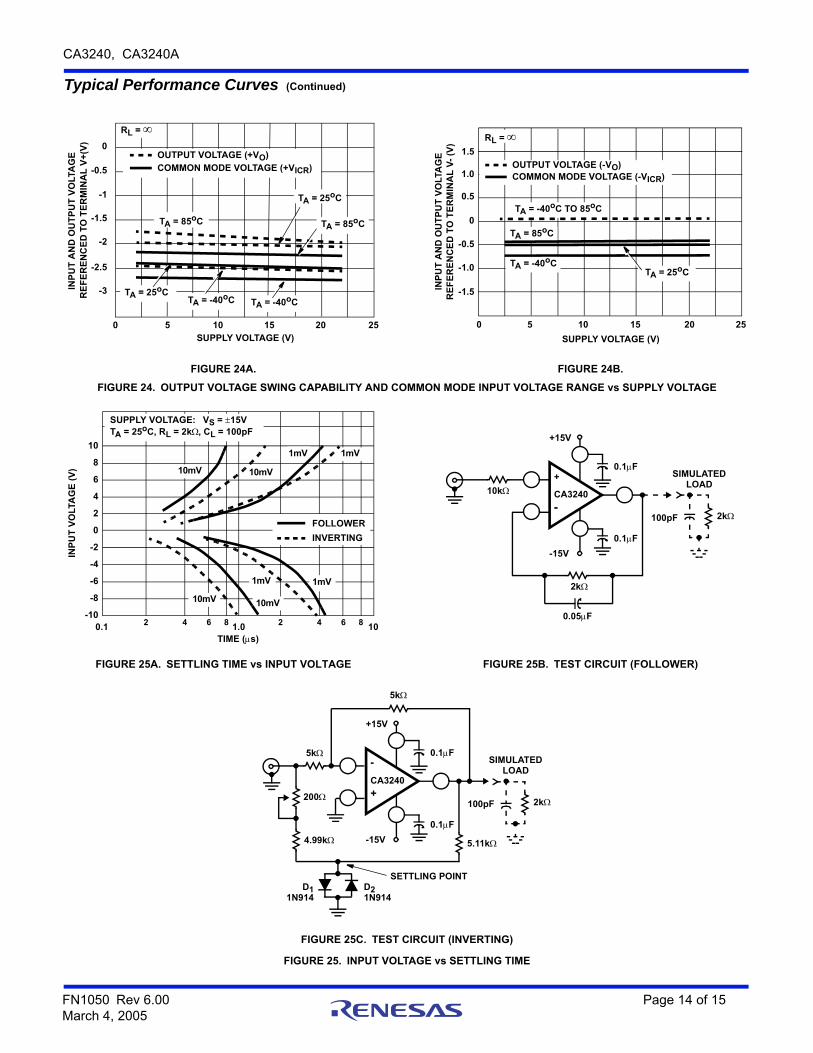
FIGURE 24A. FIGURE 24B.
FIGURE 24. OUTPUT VOLTAGE SWING CAPABILITY AND COMMON MODE INPUT VOLTAGE RANGE vs SUPPLY VOLTAGE
FIGURE 25A. SETTLING TIME vs INPUT VOLTAGE FIGURE 25B. TEST CIRCUIT (FOLLOWER)
FIGURE 25C. TEST CIRCUIT (INVERTING)
FIGURE 25. INPUT VOLTAGE vs SETTLING TIME
Typical Performance Curves (Continued)
TA = -40oCTA = 25oC
TA = -40oC
TA = 25oC
TA = 85oCTA = 85oC
RL = 0
-0.5
-1
-1.5
-2
-2.5
-3
0 5 10 15 20 25SUPPLY VOLTAGE (V)
INP
UT
AN
D O
UT
PU
T V
OLT
AG
E
RE
FE
RE
NC
ED
TO
TE
RM
INA
L V
+(V
)
OUTPUT VOLTAGE (+VO)
COMMON MODE VOLTAGE (+VICR)
TA = -40oC TO 85oC
TA = 85oC
TA = -40oCTA = 25oC
1.5
1.0
0.5
0
-0.5
-1.0
-1.5INP
UT
AN
D O
UT
PU
T V
OLT
AG
ER
EF
ER
EN
CE
D T
O T
ER
MIN
AL
V-
(V)
0 5 10 15 20 25
SUPPLY VOLTAGE (V)
RL =
OUTPUT VOLTAGE (-VO)COMMON MODE VOLTAGE (-VICR)
0.1
INP
UT
VO
LTA
GE
(V
)
1.0 102 4 6 8
SUPPLY VOLTAGE: VS = 15VTA = 25oC, RL = 2k, CL = 100pF
1mV
10mV
2 4 6 8
10mV
1mV
1mV1mV
10mV 10mV
FOLLOWER
INVERTING
10
8
6
4
2
0
-2
-4
-6
-8
-10
TIME (s)
2k
10k CA3240
+15V
-15V
0.1F
0.1F
100pF
SIMULATEDLOAD
2k
0.05F
+
-
5k
2k
5.11k4.99k
5k
200
CA3240
+15V
-15V
0.1F
0.1F
100pF
SIMULATEDLOAD
D2D11N914 1N914
SETTLING POINT
-
+
FN1050 Rev 6.00 Page 14 of 15March 4, 2005

CA3240, CA3240A
Intersil products are manufactured, assembled and tested utilizing ISO9001 quality systems as notedin the quality certifications found at www.intersil.com/en/support/qualandreliability.html
Intersil products are sold by description only. Intersil may modify the circuit design and/or specifications of products at any time without notice, provided that such modification does not, in Intersil's sole judgment, affect the form, fit or function of the product. Accordingly, the reader is cautioned to verify that datasheets are current before placing orders. Information furnished by Intersil is believed to be accurate and reliable. However, no responsibility is assumed by Intersil or its subsidiaries for its use; nor for any infringements of patents or other rights of third parties which may result from its use. No license is granted by implication or otherwise under any patent or patent rights of Intersil or its subsidiaries.
For information regarding Intersil Corporation and its products, see www.intersil.com
For additional products, see www.intersil.com/en/products.html
© Copyright Intersil Americas LLC 2002-2005. All Rights Reserved.All trademarks and registered trademarks are the property of their respective owners.
FIGURE 26. INPUT CURRENT vs TEMPERATURE FIGURE 27. OPEN LOOP VOLTAGE GAIN AND PHASE vs FREQUENCY
Typical Performance Curves (Continued)
VS = 15V
TEMPERATURE (oC)
-60 -40 -20 0 20 40 60 80 100 120 140
INP
UT
CU
RR
EN
T (
pA
) 1K
100
1
10K
10
101 103 104 105 106 107 108
FREQUENCY (Hz)
OP
EN
LO
OP
VO
LTA
GE
GA
IN (
dB
)
100
80
60
40
20
0
VS = 15VTA = 25oC
102
OP
EN
LO
OP
PH
AS
E (
DE
GR
EE
S)
-75
-90
-105
-120
-135
-150
RL = 2k,CL = 0pFPHASE
RL = 2k,CL = 100pF
GAIN
FN1050 Rev 6.00 Page 15 of 15March 4, 2005