Embed Size (px)
Citation preview

CAB COMBO WORKSHOPOWNER’S MANUAL & PARTS LIST
04.2019Revision 107
Manual Part# 164271
Caution: Read all safety and operating instructions before using this equipment. This owner's manual MUST accompany the equipment at all times.
Barranca Diamond Products, Inc.1315 Storm ParkwayTorrance, CA 90501Toll-Free: (800) 630-7682Phone: (310) 523-5867Fax: (310) 257-3063www.barrancadiamond.com
2
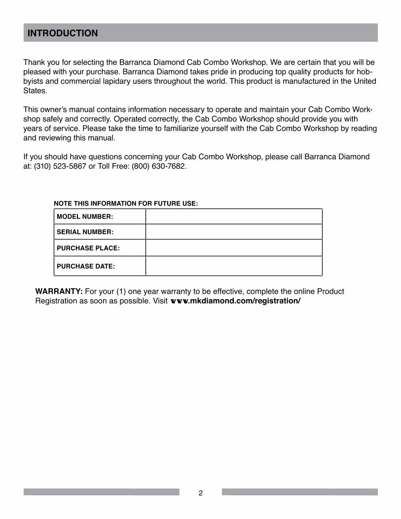
Thank you for selecting the Barranca Diamond Cab Combo Workshop. We are certain that you will be pleased with your purchase. Barranca Diamond takes pride in producing top quality products for hob-byists and commercial lapidary users throughout the world. This product is manufactured in the United States.
This owner’s manual contains information necessary to operate and maintain your Cab Combo Work-shop safely and correctly. Operated correctly, the Cab Combo Workshop should provide you with years of service. Please take the time to familiarize yourself with the Cab Combo Workshop by reading and reviewing this manual.
If you should have questions concerning your Cab Combo Workshop, please call Barranca Diamond at: (310) 523-5867 or Toll Free: (800) 630-7682.
INTRODUCTION
NOTE THIS INFORMATION FOR FUTURE USE:
MODEL NUMBER:
SERIAL NUMBER:
PURCHASE PLACE:
PURCHASE DATE:
WARRANTY: For your (1) one year warranty to be effective, complete the online Product Registration as soon as possible. Visit www.mkdiamond.com/registration/
3
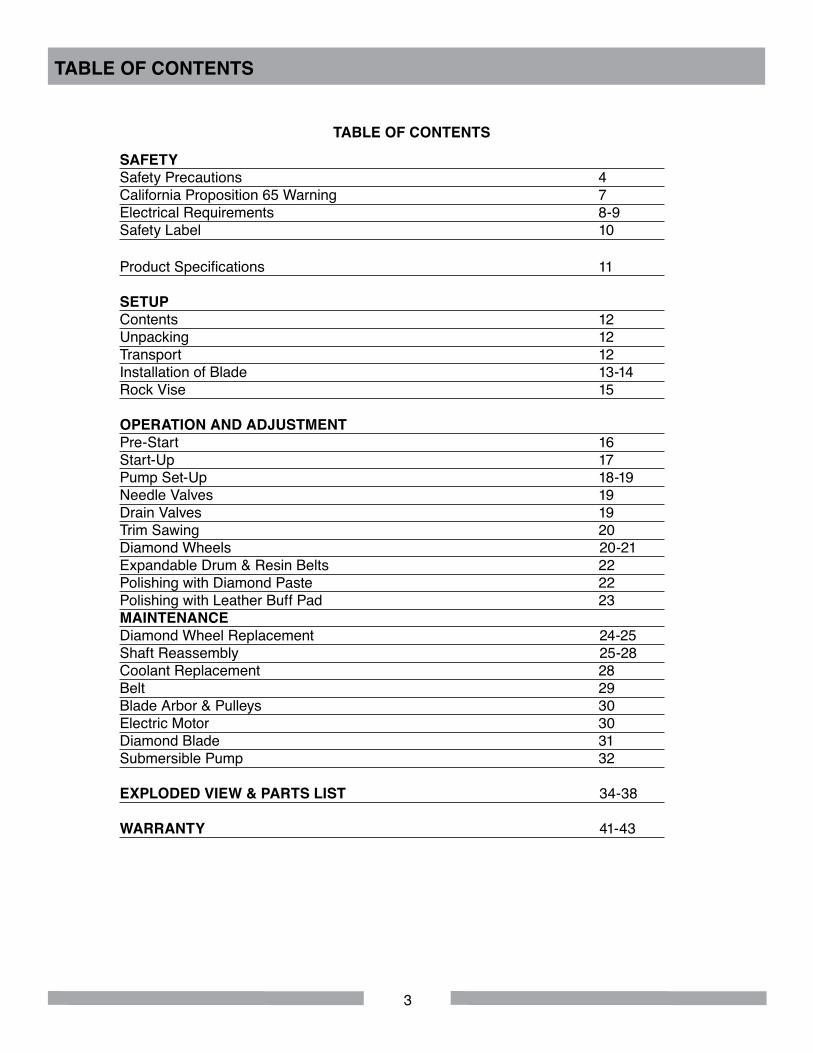
SAFETY Safety Precautions 4California Proposition 65 Warning 7Electrical Requirements 8-9Safety Label 10 Product Specifications 11
SETUP Contents 12Unpacking 12Transport 12Installation of Blade 13-14Rock Vise 15
OPERATION AND ADJUSTMENTPre-Start 16Start-Up 17Pump Set-Up 18-19Needle Valves 19Drain Valves 19Trim Sawing 20Diamond Wheels 20-21Expandable Drum & Resin Belts 22Polishing with Diamond Paste 22Polishing with Leather Buff Pad 23MAINTENANCEDiamond Wheel Replacement 24-25Shaft Reassembly 25-28Coolant Replacement 28Belt 29Blade Arbor & Pulleys 30Electric Motor 30Diamond Blade 31Submersible Pump 32
EXPLODED VIEW & PARTS LIST 34-38
WARRANTY 41-43
TABLE OF CONTENTS
TABLE OF CONTENTS
4
SAFETY PRECAUTIONS Read and follow all safety, operating and maintenance instructions. Failure to read and follow these instructions could result in injury or death to you or others. Failure to read and follow these instructions could also result in damage and/or reduced equipment life. In order to prevent injury, the following safety precautions should be followed at all times!
READ OWNER'S MANUAL BEFORE USEBefore using this equipment, ensure that the person operating this machine has read and understands all of the instructions in the manual. Precaution is the best insurance against accidents. Read and understand all safety precautions, messages, warnings and hazard symbols. You are responsible for your own safety.
ALWAYS USE SAFETY GLASSESSafety glasses should always be worn when working around power tools. In addition, a face, dust mask or respirator should be worn if a cutting operation is dusty. Everyday eyeglasses only have impact resistant lenses and may not prevent eye injury - they are NOT safety glasses.
USE PROPER APPARELDo not wear loose clothing, gloves, neckties, rings, bracelets or other jewelry that may be caught in moving parts. Non-slip footwear is recommended. Wear protective hair covering to contain long hair. Hand protection (plastic gloves) and a shop bib are recommended during sawing to prevent stains to clothing. Avoid prolonged exposure of skin to the sawing lubricant and wash skin immediately after contact. Do not touch the work material until the motor is off and the machine has come to a complete stop.
ALWAYS USE HEARING PROTECTIONTo reduce the possibility of hearing loss, always use hearing protection when operating power equipment.
KEEP GUARDS IN PLACEIn order to prevent injury, never operate the saw without the guards in place!
REMOVE ADJUSTING KEYS AND WRENCHESForm a habit of checking to see that keys and adjusting wrenches are removed from the power tool before it is turned on.
ELECTRICAL SHOCKNever touch electrical wires or motor components while the motor is running. Exposed, frayed or worn electrical wiring and plugs can be sources of electrical shock that could cause severe injury or burns. Use the GFCI (Ground Fault Circuit Interrupter Switch) included with the unit attached to the main motor power cord plug and keep plugged into the power receptacle outlet source.
CAB COMBO WORKSHOP SAFETY
5
DISCONNECT TOOLSPower tools should always be disconnected before servicing or when changing accessories, such as blades, bits, cutters and the like.
REDUCE THE RISK OF UNINTENTIONAL STARTSMake sure the ON/OFF switch is in the OFF position before plugging in a power tool.
ROTATING OR MOVING PARTSKeep hands, feet, hair, and clothing away from all moving parts to prevent injury. Never operate the engine with covers, shrouds or guards removed.
MAINTAIN TOOLS WITH CAREKeep tools clean for the best and safest performance. Always follow maintenance instructions for lubricating and when changing accessories.
KEEP WORK AREA CLEANCluttered work areas and benches invite accidents.
DO NOT USE IN DANGEROUS OR HAZARDOUS ENVIRONMENTSDo not operate equipment in dangerous or hazardous environments. Do not use power tools in damp or wet locations nor expose them to rain. Always keep the work area well lighted. Always work in a well ventilated area.
KEEP CHILDREN AWAYAll visitors and children should be kept a safe distance from the work area. Keep power cords disconnected when tool is not in use.
MAKE THE WORKSHOP KID-PROOFMake the workshops kid-proof by using padlocks, master switches and by disconnecting all power cords.
USE THE RIGHT TOOL Do not force a tool or an attachment to do a job that it was not designed to do.
SECURE WORKClamps or a vise should be used to hold work whenever practical. Keeping your hands free to operate a power tool is safer.
DO NOT FORCE THE TOOLA power tool will do a better job and operate more safely at the feed rate for which it was designed.
USE THE RIGHT TOOL TO SERVICE THE SAWDo not force a tool or an attachment when servicing or operating the Cab Combo Workshop. Use the correct tools for service or adjustments.
CAB COMBO WORKSHOP SAFETY
6
DO NOT OVERREACHKeep proper footing and balance at all times by not overreaching.
DO NOT OPERATE A TOOL WHEN TIREDWhen tired, take a break and relax.
DIRECTION OF FEEDAlways feed work into a blade or cutter in the direction shown in this manual. All blades, grinding wheels or polishing belts should always be installed such that rotation is in the direction of the arrow imprinted on the blade, wheel or belt.
ONLY OPERATE AT THE PROPER SPEEDSevere personal injury and damage to the motor or equipment can result if operated at speeds above maximum.
NEVER LEAVE A TOOL RUNNING UNATTENDED – TURN POWER OFFDo not leave a tool until it comes to a complete stop. Always turn the tool off, and disconnect the power cord to its source, when leaving the work area or when work is finished. Do not leave extension cords attached to the power cord or power receptacle (wall outlet) when leaving the work area.
CHECK FOR DAMAGED OR WORN PARTSBefore using a power tool, check for damaged parts. A guard or any other part that is damaged should be carefully checked to determine if it would operate properly and perform its intended function. Always check moving parts for proper alignment or binding. Check for broken parts and mountings and all other conditions that may affect the operation of the power tool. A guard, or any damaged part, should be properly repaired or replaced.
USE RECOMMENDED ACCESSORIES AND PARTSConsult the owner’s manual for recommended accessories and parts. Using improper parts and accessories may increase the risk of personal and/or bystander injury.
USE THE PROPER EXTENSION CORD If using an extension cord, make sure it is in good condition first. When using an extension cord, be sure to use one heavy enough to carry the current your product will draw. An undersized cord will cause a drop in line voltage that will result in a loss of power and overheating. Table on page 8 shows the correct AWG (American Wire Gauge) size to use depending on cord length and nameplate ampere rating. If in doubt, use the next heavier gauge. The smaller the gauge number, the heavier the cord.
USE A GROUND FAULT CIRCUIT INTERRUPTERUse of a Ground Fault Circuit Interrupter (GFCI) between the end of power cord and wall outlet is required at all times.
USE THE PROPER POWER SOURCEThis tool is only to be used with a 120 volt 60 HZ power source. Ensure power source is at least 15 amps and 110 to 120 volts. Low voltage current can adversely effect electric motor performance and overall life.
CAB COMBO WORKSHOP SAFETY
7
CAB COMBO WORKSHOP SAFETY
CALIFORNIA PROPOSITION 65 MESSAGE
SILICA DUST WARNINGGrinding/cutting/drilling of masonry, concrete, metal and other materials with silica in their composition may give off dust or mists containing crystalline silica. Silica is a basic component of sand, quartz, brick clay, granite and numerous other minerals and rocks. Repeated and/or substantial inhalation of airborne crystalline silica can cause serious or fatal respiratory diseases, including silicosis. In ad-dition, California and some other authorities have listed respirable crystalline silica as a substance known to cause cancer. When cutting such materials, always follow respiratory precautions.
Use appropriate NIOSH-approved respiratory protection where dust hazard may occur. Paper masks or surgical masks without a NIOSH approval number are not recommended because they do little to protect the worker. For more information about respirator programs, including what respirators have received NIOSH approval as safe and effective, please visit the NIOSH website at: http://www.cdc.gov/niosh/topics/respirators
Observe OSHA regulations for respirator use (29 C.F.R.§1910.134 and §1503.1). Visit http://www.osha.gov for more information.
USE THE RECOMMENDED COOLING AND LUBRICATING FLUIDSNever operate a tool dry that requires coolant or lubricant. This can lead to shortened tool life, tool damage and personal injury.
MAINTAIN TOOLS WITH CAREKeep the diamond blade sharp, the sawing lubricant clean and reservoir filled to the correct level for the best and safest performance. Always follow the maintenance instructions for sharpening the blade, lubricating and servicing the Cab Combo Workshop.
Some dust created by power sanding, sawing, grinding, drilling, and other construction activities con-tain chemicals known (to the State of California) to cause cancer, birth defects or other reproductive harm. Some examples of these chemicals are:
• Lead, from lead-based paints • Crystalline silica, from bricks and cement and other masonry products • Arsenic and chromium, from chemically treated lumber
For further information, consult the following sources: http://www.osha.gov/dsg/topics/silicacrystalline/index.html http://www.cdc.gov/niosh/docs/96-112/ http://oehha.ca.gov/prop65/law/P65law72003.html http://www.dir.ca.gov/Title8/sub4.htmlhttp://www.P65warnings.ca.gov
Your risk from these exposures varies depending on how often you do this type of work. To reduce your exposure to these chemicals, work in a well-ventilated area, and work with approved safety equipment, such as dust masks that are specially designed to filter out microscopic particles. Where use of a dust extraction device is possible, it should be used. To achieve a high level of dust collec-tion, use an industrial HEPA vacuum cleaner. Observe OSHA 29 CFR part 1926.57 and 1926.103.

8
ELECTRICAL REQUIREMENTS AND GROUNDING INSTRUCTIONSIn order to prevent potential electrical shock and injury, the following electrical safety precautions and symbols should be followed at all times!
In case of a malfunction or breakdown, grounding provides a path of least resistance for electric current to reduce the risk of electric shock. This tool is equipped with an electric cord having an equipment-grounding conductor and a grounding plug. The plug must be plugged into a matching outlet that is properly installed and grounded in accordance with all local codes and ordinances.• Do not modify the plug provided – if it will not fit the outlet; have the proper outlet installed by a
qualified electrician.• Improper connections of the equipment-grounding conductor can result in a risk of electric shock.
The equipment-grounding conductor is the wire that has a green outter surface, with or without yellow stripes. If repair or replacement of the electric cord or plug is necessary, do not connect the equipment-grounding conductor to a live terminal.
• Check with a qualified electrician or service personnel if the grounding instructions are not completely understood, or if in doubt as to whether the tool is properly grounded.
• Use only 3-wire extension cords that have 3-prong grounding plugs and 3-pole receptacles that accept the tool’s plug.
• Repair or replace a damaged or worn cord immediately.
This tool is intended for use on a circuit that has an outlet that looks like the one shown in Sketch A. The tool has a grounding plug that looks like the plug illustrated in Sketch A. A temporary adapter, which looks like the adapter illustrated in sketches B and C, may be used to connect this plug to a 2-pole receptacle as shown in Sketch B, if a properly grounded outlet is not available. The temporary adapter should be used only until a properly grounded outlet can be installed by a qualified electri-cian. The green-colored rigid ear, plug, and the like, extending from the adapter, must be connected to a permanent ground, such as a properly grounded outlet box.
NOTE: Use of a temporary adapter is not permitted in Canada.
To reduce the risk of electrocution, keep all connections dry and off the ground.
A Ground Fault Circuit Interrupter (GFCI) should be provided on the circuit(s) or outlet(s) to be used for this power tool. Receptacles are available, having built-in GFCI protection, and may be used for this measure of safety.
When using an extension cord, the GFCI should be installed closest to the power source, followed by the extension cord, and lastly, the saw.
CAB COMBO WORKSHOP SAFETY
GroundingMeans
(A)
Metal Screw
Cover of GroundedOutlet Box
(D)
ADAPTER
(C)Grounding
Pin
GroundingPin (B)
Circuit and Adapter Information

9
CAB COMBO WORKSHOP SAFETY
To avoid the possibility of the appliance plug or receptacle getting wet, position the tool to one side of a wall mounted receptacle. This will prevent water from dripping onto the receptacle or plug. A “drip loop," shown in Fig 2, should be arranged by the user to properly position the power cord relative to the power source.
The “drip loop" is the part of the cord below the level of the receptacle, or the connector, if an extension cord is used. This method of positioning the cord prevents the travel of water along the power cord and coming in contact with the receptacle.
If the plug or receptacle gets wet, DO NOT unplug the cord. Disconnect the fuse or circuit breaker that supplies power to the tool. Then unplug and examine for presence of water in the receptacle.
Use only extension cords that are intended for outdoor use. These extension cords are identified by a marking “Acceptable for use with outdoor appliances; store indoors while not in use." Use only extension cords having an electrical rating not less than the rating of the product. Do not use damaged extension cords. Examine extension cords before using and replace if damaged. Do not abuse extension cords and do not yank on any cord to disconnect. Keep cords away from heat and sharp edges. Always disconnect the extension cord from the receptacle before
disconnecting the product from the extension cord.
To reduce the risk of electrocution, keep all connections dry and off the ground. Don't touch the plug with wet hands.
Use of undersized extension cords will result in low voltage to the motor that can result in motor burnout and premature failure. Barranca Diamond warns that equipment returned to us showing signs of being run in a low voltage condition, through the use of undersized extension cords, will be repaired or replaced totally at the customer's expense. There will be no warranty claim.
To choose the proper extension cord:• Locate the length of extension cord needed in Table below.• Once the proper length is found, move down the column to obtain the correct AWG size required for
that length of extension cord.
Drip Loop
MOTOR SPECS EXTENSION CORD LENGTHMotor Voltage Amps 25' 50' 100' 200’
161672 115V 1 Ph 3.3 18 ga 16 ga 14 ga 10 ga
ELECTRICAL REQUIREMENTS AND GROUNDING INSTRUCTIONS
10
CAB COMBO WORKSHOP SAFETY
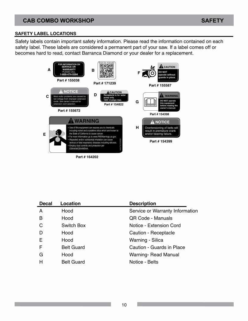
Safety labels contain important safety information. Please read the information contained on each safety label. These labels are considered a permanent part of your saw. If a label comes off or becomes hard to read, contact Barranca Diamond or your dealer for a replacement.
SAFETY LABEL LOCATIONS
Decal Location DescriptionA Hood Service or Warranty Information B Hood QR Code - ManualsC Switch Box Notice - Extension Cord D Hood Caution - ReceptacleE Hood Warning - SilicaF Belt Guard Caution - Guards in PlaceG Hood Warning- Read ManualH Belt Guard Notice - Belts
Part # 164202
E
F
C
A
H
B
Part # 155587
CAUTION
DO NOToperate without guards in place.
!
Part # 155038
SERVICE OR WARRANTY
FOR INFORMATION ON
PLEASE CALL1-800-474-5594
Part # 171239
Part # 154399
NOTICEOvertensioning of belts will result in premature crank and/or bearing failure.
!
Scan for manuals
Part # 155672
NOTICEMost motor problems are caused by low voltage from improper extension cords. See owner’s manual for extension cord selection.
!
G
Part # 154398
DO NOT operate this equipment before reading the owner’s manual.
WARNING!D
Part # 154822
Receptacle is for water pump only. 125V .6 amps max.
! CAUTION
WARNING• Use of this equipment can expose you to chemicals including nickel and crystalline silica which are known to the State of California to cause cancer. • For more information go to www.P65Warnings.ca.gov. • Repeated and/or substantial inhalation can cause serious or fatal respiratory diseases including silicosis. • Employ dust controls and protection per OSHA/NIOSH/MSHA.
!La
bel P
art #
1642
02

11
Part #8300011 Carbide wheels and diamond beltsPart #8300012 Diamond wheels and diamond beltsPart #8300010 Carbide configuration without motor, GFCI, switch & base boardPart #8300013 Diamond configuration without motor, GFCI, switch & base boardPart #8300014 No wheels, belts, blade, GFCI, switch, motor, base board or polishing supplies
Horsepower 1/3 HPMotor Voltage/Frequency 110 volt/60 HzAmperage 5.8 AmpsMotor RPM 1725Motor Arbor Diameter 1/2"Duty Continuous, automatic thermal protection shut-offMotor Arbor Bearings Ball bearings, permanently sealedBlade Capacity 6" diameterSaw Lubricant Oil or water with rust inhibitor (Tool Cool)Motor and Shaft Pulley 2" OD x 5/8" bore (shaft) and 2" OD x 1/2" bore (motor)Shaft Bearings Permanently sealed 5/8" OD shaft ball bearings Blade Arbor Flanges 2" OD x 5/8" bore aluminumMaximum Depth of Cut Not to exceed 1" for most cutsBrazed Diamond Wheel 80 and 200 gritDiamond Resin Belts 400, 600, 1200 and 3000 grit 6" x 1-1/2" wide belt sizeExpandable Rubber Drum 6" x 1-1/2" wide x 5/8" arborShaft Type 5/8" precision-machined stainless steelWheel and Blade Flanges Aluminum 2" OD x 5/8" boreWheel Spacers 7/8" OD x 5/8" ID aluminum (length varies for wheels and drum)Convex Polishing End Hub 6" aluminum hub disc with 5/8"-11 right hand thread
Lubricant capacity of reservoir tank: 1/4 gallon will cover 1/4" of 6" blade.
Pump: MK Submersible pump (part #155987-VP), variable flow control with 1/4" ID tubing.
Water Control Valves: 3 stainless steel control valves, brass lever cock valve with barb for 1/4" ID tub-ing mounted on rear of the hood.
ON/OFF Switch Box: Lever operated switch box and pigtail female plug receptacle for submersible pump.
Standard Polishing Supplies: Three 6" Polytex pads, three diamond paste syringes (5 grams ea.), diamond paste (8,000, 14,000 and 50,000 grit), 6" leather buffing pad, 100 grit green silicon carbide blade sharpening stick (1" x 1" x 6"), 3M On-Off cement, submersible pump, 1/4" ID clear tubing, 3/8" ID clear tubing and GFCI.
CAB COMBO WORKSHOP SPECIFICATIONS
CAB COMBINATION WORKSHOP SPECIFICATIONS
12
CONTENTSIn the shipping crate, you will find one Barranca Diamond Cab Combo Workshop, one 6" x 0.020 x 5/8" 303 Pro diamond blade, one Ground Fault Circuit Interrupter (GFCI) and one 1" x 1" x 6" sharpening stick.
If included as part of your specific order you will also find a variety of accessories.
UNPACKING Your Cab Combo Workshop has been shipped from the factory thoroughly inspected and tested. Re-move the crating material (wood and plastic) from the baseboard and around the machine carefully us-ing Phillips and standard screwdrivers, and a box cutter knife. Any accessories should be removed from the unit and put aside.
TRANSPORTFor safe transport, lubricant should be removed from the saw tank coolant and wheel reservoirs of the Cab Combo Workshop. Removal of the 6" diamond blade is recommended to prevent damage during transport.
CAB COMBO WORKSHOP SETUP
13
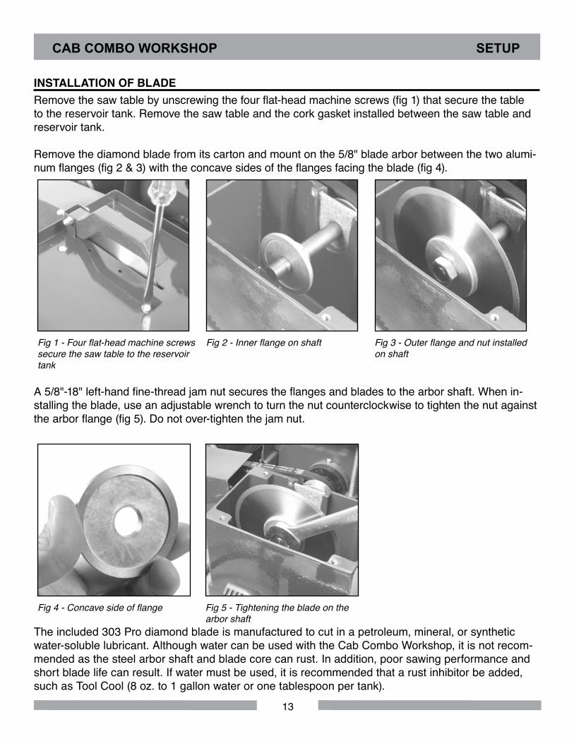
Remove the saw table by unscrewing the four flat-head machine screws (fig 1) that secure the table to the reservoir tank. Remove the saw table and the cork gasket installed between the saw table and reservoir tank.
Remove the diamond blade from its carton and mount on the 5/8" blade arbor between the two alumi-num flanges (fig 2 & 3) with the concave sides of the flanges facing the blade (fig 4).
Fig 1 - Four flat-head machine screws secure the saw table to the reservoir tank
Fig 2 - Inner flange on shaft Fig 3 - Outer flange and nut installed on shaft
A 5/8"-18" left-hand fine-thread jam nut secures the flanges and blades to the arbor shaft. When in-stalling the blade, use an adjustable wrench to turn the nut counterclockwise to tighten the nut against the arbor flange (fig 5). Do not over-tighten the jam nut.
Fig 4 - Concave side of flange Fig 5 - Tightening the blade on the arbor shaft
The included 303 Pro diamond blade is manufactured to cut in a petroleum, mineral, or synthetic water-soluble lubricant. Although water can be used with the Cab Combo Workshop, it is not recom-mended as the steel arbor shaft and blade core can rust. In addition, poor sawing performance and short blade life can result. If water must be used, it is recommended that a rust inhibitor be added, such as Tool Cool (8 oz. to 1 gallon water or one tablespoon per tank).
CAB COMBO WORKSHOP SETUP
INSTALLATION OF BLADE
14
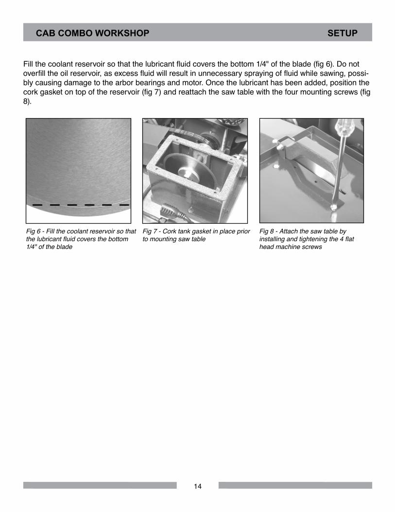
Fill the coolant reservoir so that the lubricant fluid covers the bottom 1/4" of the blade (fig 6). Do not overfill the oil reservoir, as excess fluid will result in unnecessary spraying of fluid while sawing, possi-bly causing damage to the arbor bearings and motor. Once the lubricant has been added, position the cork gasket on top of the reservoir (fig 7) and reattach the saw table with the four mounting screws (fig 8).
Fig 6 - Fill the coolant reservoir so that the lubricant fluid covers the bottom 1/4" of the blade
Fig 7 - Cork tank gasket in place prior to mounting saw table
Fig 8 - Attach the saw table by installing and tightening the 4 flat head machine screws
CAB COMBO WORKSHOP SETUP
15
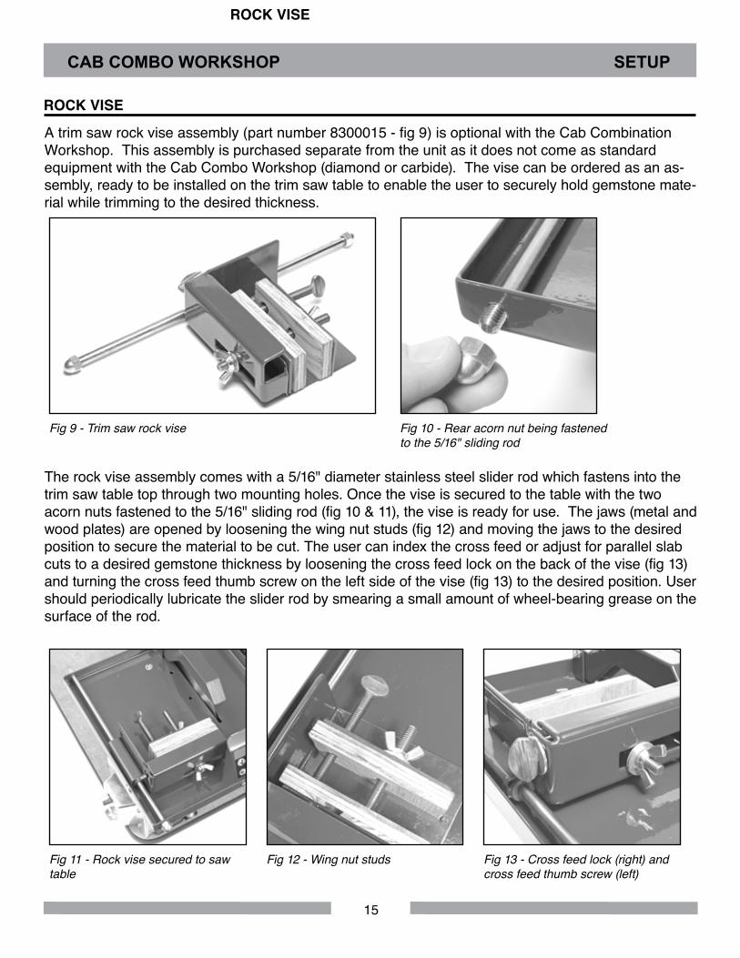
A trim saw rock vise assembly (part number 8300015 - fig 9) is optional with the Cab Combination Workshop. This assembly is purchased separate from the unit as it does not come as standard equipment with the Cab Combo Workshop (diamond or carbide). The vise can be ordered as an as-sembly, ready to be installed on the trim saw table to enable the user to securely hold gemstone mate-rial while trimming to the desired thickness.
Fig 9 - Trim saw rock vise Fig 10 - Rear acorn nut being fastened to the 5/16" sliding rod
The rock vise assembly comes with a 5/16" diameter stainless steel slider rod which fastens into the trim saw table top through two mounting holes. Once the vise is secured to the table with the two acorn nuts fastened to the 5/16" sliding rod (fig 10 & 11), the vise is ready for use. The jaws (metal and wood plates) are opened by loosening the wing nut studs (fig 12) and moving the jaws to the desired position to secure the material to be cut. The user can index the cross feed or adjust for parallel slab cuts to a desired gemstone thickness by loosening the cross feed lock on the back of the vise (fig 13) and turning the cross feed thumb screw on the left side of the vise (fig 13) to the desired position. User should periodically lubricate the slider rod by smearing a small amount of wheel-bearing grease on the surface of the rod.
Fig 11 - Rock vise secured to saw table
Fig 12 - Wing nut studs Fig 13 - Cross feed lock (right) and cross feed thumb screw (left)
CAB COMBO WORKSHOP SETUP
ROCK VISE
ROCK VISE
16
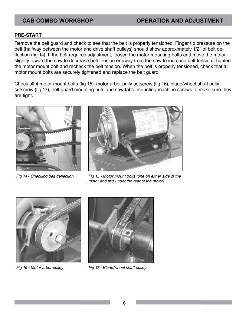
Remove the belt guard and check to see that the belt is properly tensioned. Finger tip pressure on the belt (halfway between the motor and drive shaft pulleys) should show approximately 1/2" of belt de-flection (fig 14). If the belt requires adjustment, loosen the motor mounting bolts and move the motor slightly toward the saw to decrease belt tension or away from the saw to increase belt tension. Tighten the motor mount bolt and recheck the belt tension. When the belt is properly tensioned, check that all motor mount bolts are securely tightened and replace the belt guard.
Check all 4 motor mount bolts (fig 15), motor arbor pully setscrew (fig 16), blade/wheel shaft pully setscrew (fig 17), belt guard mounting nuts and saw table mounting machine screws to make sure they are tight.
Fig 14 - Checking belt deflection Fig 15 - Motor mount bolts (one on either side of the motor and two under the rear of the motor)
Fig 16 - Motor arbor pulley Fig 17 - Blade/wheel shaft pulley
CAB COMBO WORKSHOP OPERATION AND ADJUSTMENT
PRE-START
17
Fig 19 - Power switch in the OFF position
Fig 20 - GFCI reset button Fig 21 - Power switch in the ON position
The Cab Combo Workshop is now ready for a power up test to be performed. Turn the lever to the ON position (fig 21) on the switch box. Make sure no unusual sounds or vibrations occur when the motor engages. If the shaft or motor pulley should loosen, they may hit the sides of the saw tank, hood, mo-tor or belt guard causing a rubbing noise. If this happens, shut off the unit, unplug the power cord from the switch box and adjust, align, and securely retighten the pulleys with an Allen wrench. Liquid thread locker (removable type) can be used on the setscrew threads to prevent loosening.
Fig 18 - GFCI
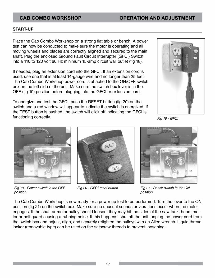
Place the Cab Combo Workshop on a strong flat table or bench. A power test can now be conducted to make sure the motor is operating and all moving wheels and blades are correctly aligned and secured to the main shaft. Plug the enclosed Ground Fault Circuit Interrupter (GFCI) Switch into a 110 to 120 volt 60 Hz minimum 15-amp circuit wall outlet (fig 18).
If needed, plug an extension cord into the GFCI. If an extension cord is used, use one that is at least 14-gauge wire and no longer than 25 feet. The Cab Combo Workshop power cord is attached to the ON/OFF switch box on the left side of the unit. Make sure the switch box lever is in the OFF (fig 19) position before plugging into the GFCI or extension cord.
To energize and test the GFCI, push the RESET button (fig 20) on the switch and a red window will appear to indicate the switch is energized. If the TEST button is pushed, the switch will click off indicating the GFCI is functioning correctly.
CAB COMBO WORKSHOP OPERATION AND ADJUSTMENT
START-UP
18
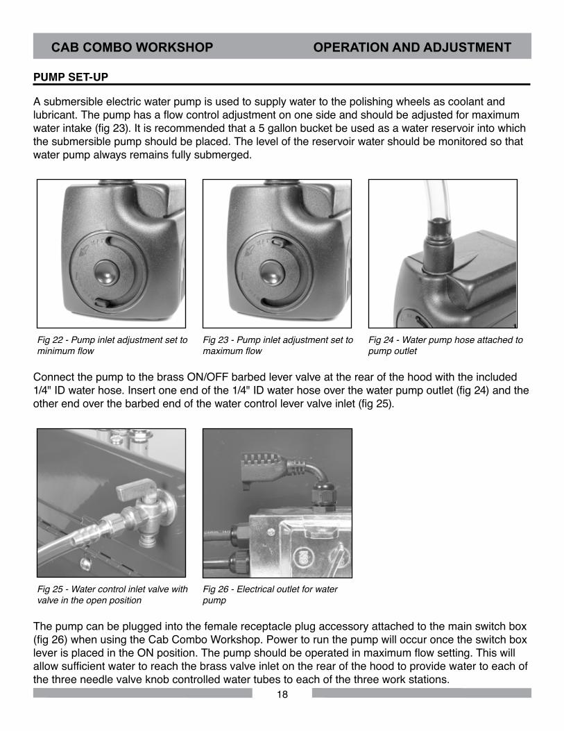
A submersible electric water pump is used to supply water to the polishing wheels as coolant and lubricant. The pump has a flow control adjustment on one side and should be adjusted for maximum water intake (fig 23). It is recommended that a 5 gallon bucket be used as a water reservoir into which the submersible pump should be placed. The level of the reservoir water should be monitored so that water pump always remains fully submerged.
Fig 22 - Pump inlet adjustment set to minimum flow
Fig 23 - Pump inlet adjustment set to maximum flow
Fig 24 - Water pump hose attached to pump outlet
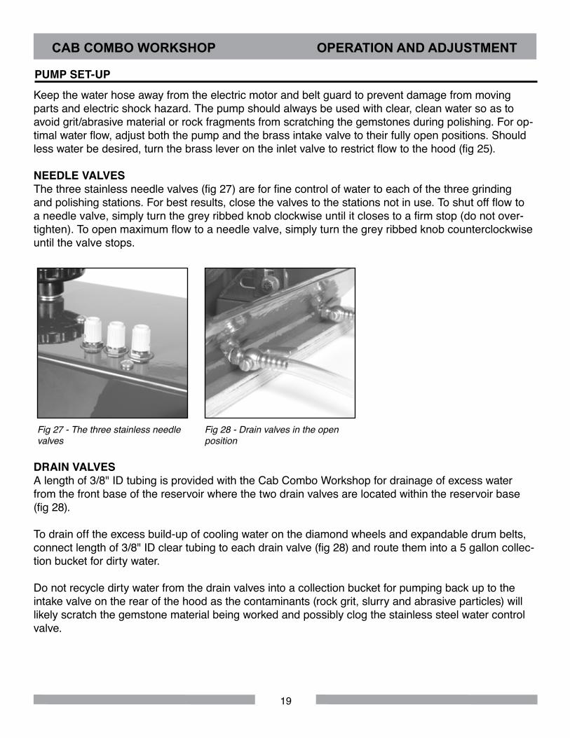
Connect the pump to the brass ON/OFF barbed lever valve at the rear of the hood with the included 1/4" ID water hose. Insert one end of the 1/4" ID water hose over the water pump outlet (fig 24) and the other end over the barbed end of the water control lever valve inlet (fig 25).
Fig 25 - Water control inlet valve with valve in the open position
Fig 26 - Electrical outlet for water pump
The pump can be plugged into the female receptacle plug accessory attached to the main switch box (fig 26) when using the Cab Combo Workshop. Power to run the pump will occur once the switch box lever is placed in the ON position. The pump should be operated in maximum flow setting. This will allow sufficient water to reach the brass valve inlet on the rear of the hood to provide water to each of the three needle valve knob controlled water tubes to each of the three work stations.
CAB COMBO WORKSHOP OPERATION AND ADJUSTMENT
PUMP SET-UP
19
Keep the water hose away from the electric motor and belt guard to prevent damage from moving parts and electric shock hazard. The pump should always be used with clear, clean water so as to avoid grit/abrasive material or rock fragments from scratching the gemstones during polishing. For op-timal water flow, adjust both the pump and the brass intake valve to their fully open positions. Should less water be desired, turn the brass lever on the inlet valve to restrict flow to the hood (fig 25).
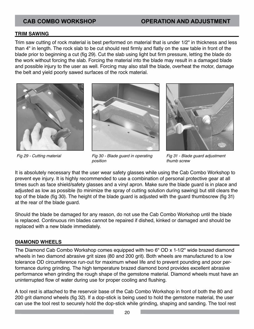
NEEDLE VALVESThe three stainless needle valves (fig 27) are for fine control of water to each of the three grinding and polishing stations. For best results, close the valves to the stations not in use. To shut off flow to a needle valve, simply turn the grey ribbed knob clockwise until it closes to a firm stop (do not over-tighten). To open maximum flow to a needle valve, simply turn the grey ribbed knob counterclockwise until the valve stops.
Fig 27 - The three stainless needle valves
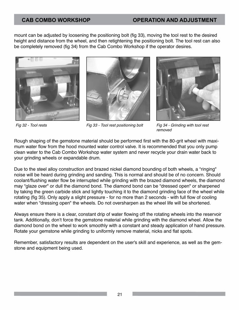
Fig 28 - Drain valves in the open position
DRAIN VALVESA length of 3/8" ID tubing is provided with the Cab Combo Workshop for drainage of excess water from the front base of the reservoir where the two drain valves are located within the reservoir base (fig 28).
To drain off the excess build-up of cooling water on the diamond wheels and expandable drum belts, connect length of 3/8" ID clear tubing to each drain valve (fig 28) and route them into a 5 gallon collec-tion bucket for dirty water.
Do not recycle dirty water from the drain valves into a collection bucket for pumping back up to the intake valve on the rear of the hood as the contaminants (rock grit, slurry and abrasive particles) will likely scratch the gemstone material being worked and possibly clog the stainless steel water control valve.
CAB COMBO WORKSHOP OPERATION AND ADJUSTMENT
PUMP SET-UP
20
Trim saw cutting of rock material is best performed on material that is under 1/2" in thickness and less than 4" in length. The rock slab to be cut should rest firmly and flatly on the saw table in front of the blade prior to beginning a cut (fig 29). Cut the slab using light but firm pressure, letting the blade do the work without forcing the slab. Forcing the material into the blade may result in a damaged blade and possible injury to the user as well. Forcing may also stall the blade, overheat the motor, damage the belt and yield poorly sawed surfaces of the rock material.
Fig 29 - Cutting material Fig 30 - Blade guard in operating position
Fig 31 - Blade guard adjustment thumb screw
It is absolutely necessary that the user wear safety glasses while using the Cab Combo Workshop to prevent eye injury. It is highly recommended to use a combination of personal protective gear at all times such as face shield/safety glasses and a vinyl apron. Make sure the blade guard is in place and adjusted as low as possible (to minimize the spray of cutting solution during sawing) but still clears the top of the blade (fig 30). The height of the blade guard is adjusted with the guard thumbscrew (fig 31) at the rear of the blade guard.
Should the blade be damaged for any reason, do not use the Cab Combo Workshop until the blade is replaced. Continuous rim blades cannot be repaired if dished, kinked or damaged and should be replaced with a new blade immediately.
CAB COMBO WORKSHOP OPERATION AND ADJUSTMENT
DIAMOND WHEELSThe Diamond Cab Combo Workshop comes equipped with two 6" OD x 1-1/2" wide brazed diamond wheels in two diamond abrasive grit sizes (80 and 200 grit). Both wheels are manufactured to a low tolerance OD circumference run-out for maximum wheel life and to prevent pounding and poor per-formance during grinding. The high temperature brazed diamond bond provides excellent abrasive performance when grinding the rough shape of the gemstone material. Diamond wheels must have an uninterrupted flow of water during use for proper cooling and flushing.
A tool rest is attached to the reservoir base of the Cab Combo Workshop in front of both the 80 and 200 grit diamond wheels (fig 32). If a dop-stick is being used to hold the gemstone material, the user can use the tool rest to securely hold the dop-stick while grinding, shaping and sanding. The tool rest
TRIM SAWING
21
mount can be adjusted by loosening the positioning bolt (fig 33), moving the tool rest to the desired height and distance from the wheel, and then retightening the positioning bolt. The tool rest can also be completely removed (fig 34) from the Cab Combo Workshop if the operator desires.
Fig 32 - Tool rests Fig 33 - Tool rest positioning bolt Fig 34 - Grinding with tool rest removed
Rough shaping of the gemstone material should be performed first with the 80-grit wheel with maxi-mum water flow from the hood mounted water control valve. It is recommended that you only pump clean water to the Cab Combo Workshop water system and never recycle your drain water back to your grinding wheels or expandable drum.
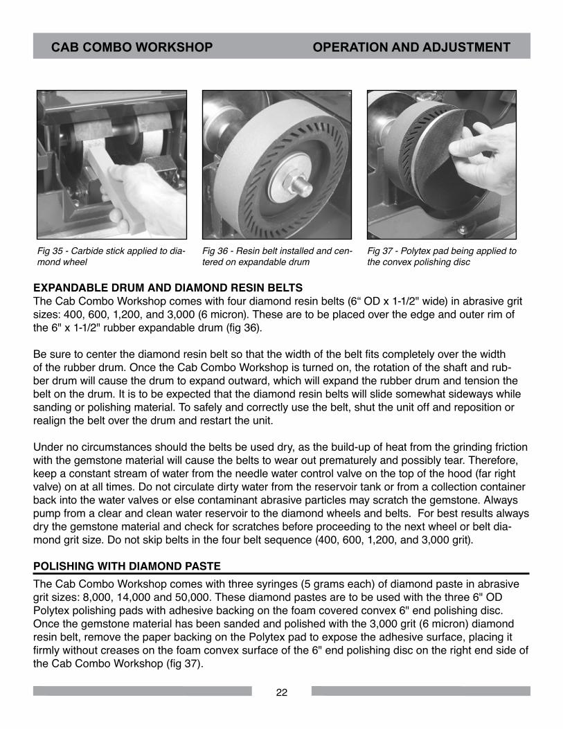
Due to the steel alloy construction and brazed nickel diamond bounding of both wheels, a “ringing" noise will be heard during grinding and sanding. This is normal and should be of no concern. Should coolant/flushing water flow be interrupted while grinding with the brazed diamond wheels, the diamond may “glaze over" or dull the diamond bond. The diamond bond can be “dressed open" or sharpened by taking the green carbide stick and lightly touching it to the diamond grinding face of the wheel while rotating (fig 35). Only apply a slight pressure - for no more than 2 seconds - with full flow of cooling water when “dressing open" the wheels. Do not oversharpen as the wheel life will be shortened.
Always ensure there is a clear, constant drip of water flowing off the rotating wheels into the reservoir tank. Additionally, don’t force the gemstone material while grinding with the diamond wheel. Allow the diamond bond on the wheel to work smoothly with a constant and steady application of hand pressure. Rotate your gemstone while grinding to uniformly remove material, nicks and flat spots.
Remember, satisfactory results are dependent on the user's skill and experience, as well as the gem-stone and equipment being used.
CAB COMBO WORKSHOP OPERATION AND ADJUSTMENT
22
Fig 35 - Carbide stick applied to dia-mond wheel
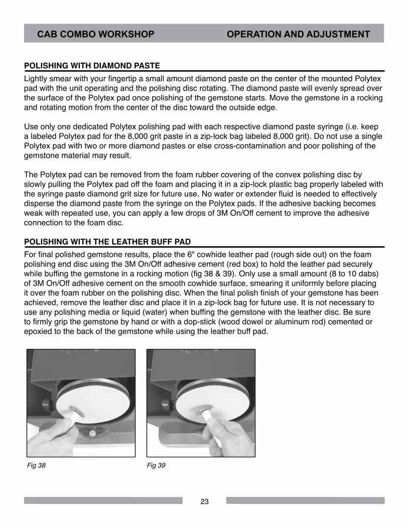
Fig 36 - Resin belt installed and cen-tered on expandable drum
Fig 37 - Polytex pad being applied to the convex polishing disc
EXPANDABLE DRUM AND DIAMOND RESIN BELTSThe Cab Combo Workshop comes with four diamond resin belts (6“ OD x 1-1/2" wide) in abrasive grit sizes: 400, 600, 1,200, and 3,000 (6 micron). These are to be placed over the edge and outer rim of the 6" x 1-1/2" rubber expandable drum (fig 36).
Be sure to center the diamond resin belt so that the width of the belt fits completely over the width of the rubber drum. Once the Cab Combo Workshop is turned on, the rotation of the shaft and rub-ber drum will cause the drum to expand outward, which will expand the rubber drum and tension the belt on the drum. It is to be expected that the diamond resin belts will slide somewhat sideways while sanding or polishing material. To safely and correctly use the belt, shut the unit off and reposition or realign the belt over the drum and restart the unit.
Under no circumstances should the belts be used dry, as the build-up of heat from the grinding friction with the gemstone material will cause the belts to wear out prematurely and possibly tear. Therefore, keep a constant stream of water from the needle water control valve on the top of the hood (far right valve) on at all times. Do not circulate dirty water from the reservoir tank or from a collection container back into the water valves or else contaminant abrasive particles may scratch the gemstone. Always pump from a clear and clean water reservoir to the diamond wheels and belts. For best results always dry the gemstone material and check for scratches before proceeding to the next wheel or belt dia-mond grit size. Do not skip belts in the four belt sequence (400, 600, 1,200, and 3,000 grit).
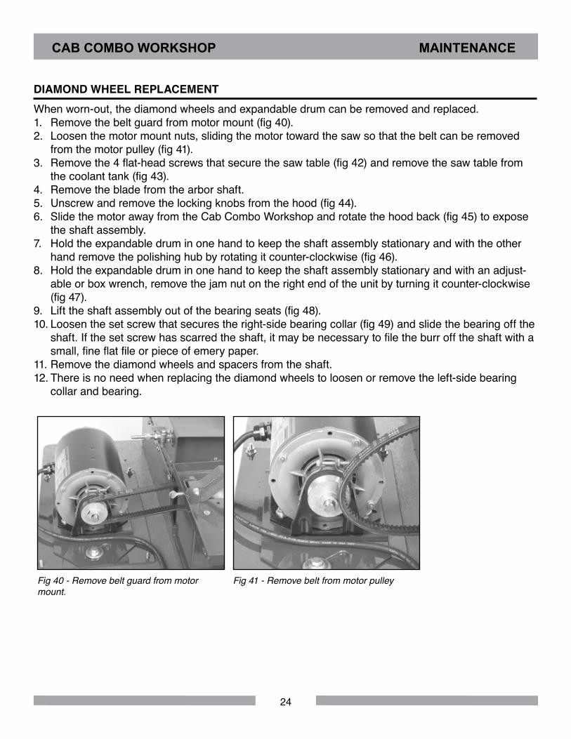
POLISHING WITH DIAMOND PASTEThe Cab Combo Workshop comes with three syringes (5 grams each) of diamond paste in abrasive grit sizes: 8,000, 14,000 and 50,000. These diamond pastes are to be used with the three 6" OD Polytex polishing pads with adhesive backing on the foam covered convex 6" end polishing disc. Once the gemstone material has been sanded and polished with the 3,000 grit (6 micron) diamond resin belt, remove the paper backing on the Polytex pad to expose the adhesive surface, placing it firmly without creases on the foam convex surface of the 6" end polishing disc on the right end side of the Cab Combo Workshop (fig 37).
CAB COMBO WORKSHOP OPERATION AND ADJUSTMENT
23
POLISHING WITH DIAMOND PASTELightly smear with your fingertip a small amount diamond paste on the center of the mounted Polytex pad with the unit operating and the polishing disc rotating. The diamond paste will evenly spread over the surface of the Polytex pad once polishing of the gemstone starts. Move the gemstone in a rocking and rotating motion from the center of the disc toward the outside edge.
Use only one dedicated Polytex polishing pad with each respective diamond paste syringe (i.e. keep a labeled Polytex pad for the 8,000 grit paste in a zip-lock bag labeled 8,000 grit). Do not use a single Polytex pad with two or more diamond pastes or else cross-contamination and poor polishing of the gemstone material may result.
The Polytex pad can be removed from the foam rubber covering of the convex polishing disc by slowly pulling the Polytex pad off the foam and placing it in a zip-lock plastic bag properly labeled with the syringe paste diamond grit size for future use. No water or extender fluid is needed to effectively disperse the diamond paste from the syringe on the Polytex pads. If the adhesive backing becomes weak with repeated use, you can apply a few drops of 3M On/Off cement to improve the adhesive connection to the foam disc.
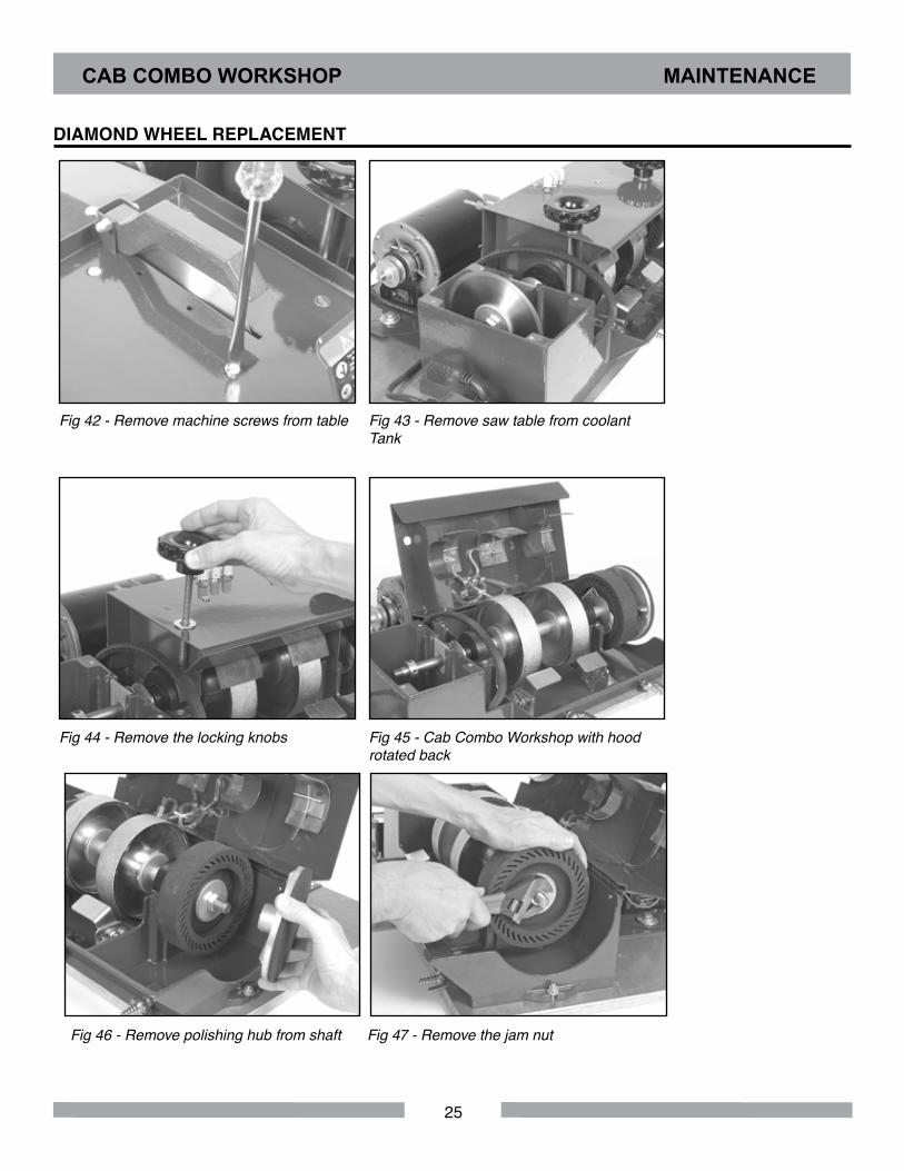
POLISHING WITH THE LEATHER BUFF PADFor final polished gemstone results, place the 6" cowhide leather pad (rough side out) on the foam polishing end disc using the 3M On/Off adhesive cement (red box) to hold the leather pad securely while buffing the gemstone in a rocking motion (fig 38 & 39). Only use a small amount (8 to 10 dabs) of 3M On/Off adhesive cement on the smooth cowhide surface, smearing it uniformly before placing it over the foam rubber on the polishing disc. When the final polish finish of your gemstone has been achieved, remove the leather disc and place it in a zip-lock bag for future use. It is not necessary to use any polishing media or liquid (water) when buffing the gemstone with the leather disc. Be sure to firmly grip the gemstone by hand or with a dop-stick (wood dowel or aluminum rod) cemented or epoxied to the back of the gemstone while using the leather buff pad.
Fig 38 Fig 39
CAB COMBO WORKSHOP OPERATION AND ADJUSTMENT
24
DIAMOND WHEEL REPLACEMENTWhen worn-out, the diamond wheels and expandable drum can be removed and replaced. 1. Remove the belt guard from motor mount (fig 40).2. Loosen the motor mount nuts, sliding the motor toward the saw so that the belt can be removed
from the motor pulley (fig 41).3. Remove the 4 flat-head screws that secure the saw table (fig 42) and remove the saw table from
the coolant tank (fig 43).4. Remove the blade from the arbor shaft.5. Unscrew and remove the locking knobs from the hood (fig 44).6. Slide the motor away from the Cab Combo Workshop and rotate the hood back (fig 45) to expose
the shaft assembly.7. Hold the expandable drum in one hand to keep the shaft assembly stationary and with the other
hand remove the polishing hub by rotating it counter-clockwise (fig 46).8. Hold the expandable drum in one hand to keep the shaft assembly stationary and with an adjust-
able or box wrench, remove the jam nut on the right end of the unit by turning it counter-clockwise (fig 47).
9. Lift the shaft assembly out of the bearing seats (fig 48).10. Loosen the set screw that secures the right-side bearing collar (fig 49) and slide the bearing off the
shaft. If the set screw has scarred the shaft, it may be necessary to file the burr off the shaft with a small, fine flat file or piece of emery paper.
11. Remove the diamond wheels and spacers from the shaft.12. There is no need when replacing the diamond wheels to loosen or remove the left-side bearing
collar and bearing.
Fig 40 - Remove belt guard from motor mount.
Fig 41 - Remove belt from motor pulley
CAB COMBO WORKSHOP MAINTENANCE
25
DIAMOND WHEEL REPLACEMENT
Fig 42 - Remove machine screws from table Fig 43 - Remove saw table from coolant Tank
Fig 44 - Remove the locking knobs Fig 45 - Cab Combo Workshop with hood rotated back
CAB COMBO WORKSHOP MAINTENANCE
Fig 46 - Remove polishing hub from shaft Fig 47 - Remove the jam nut

26
Fig 48 - Shaft assembly removed from Cab Combo Workshop
Fig 49 - Loosen the set screw that secures the right-side bearing collar
SHAFT REASSEMBLY
Fig 50 - Diamond wheel shaft assembly (shown without diamond wheels and polishing drum)
Reassembly of the shaft with the new diamond wheels is the reverse of the disassembly instructions. Please keep the following points in mind when reassembling:1. Install diamond wheels with the inside faces facing each other (fig 51 & 52). Be sure the diamond
wheel bushings are installed (fig 50).2. The bearings have a permanently mounted bushing that extend from one side of the center
bearing. This extension must face away from the diamond wheels (fig 53 & 54) on both ends of the arbor shaft.
3. The arbor shaft collars have one recessed side and one flat side (fig 55 & 56). The recessed side should face the bearing and mate against the extended portion of the bearing bushing.
4. There should be a flange installed on both sides of each diamond wheel and the expandable drum. Make sure the concave side of the flange (fig 4) faces the wheels and drum.
5. When tightening the set screw in the right side bearing collar, stand the arbor shaft up on end (blade end of the shaft on the floor) and push down with a light to medium pressure on the bearing collar. This will provide enough compression between the shaft components so that the diamond wheels and expandable drum do not become disengaged from the shaft during grinding and pol-ishing operations.
1-1/4"Spacer
1-5/16"Spacer
3-5/16"Spacer
1"Spacer
Bearing Collar
WheelBushing
WheelBushing
DrumBushingBearing
FlangeBearingCollar
SplashGuard
CAB COMBO WORKSHOP MAINTENANCE
27
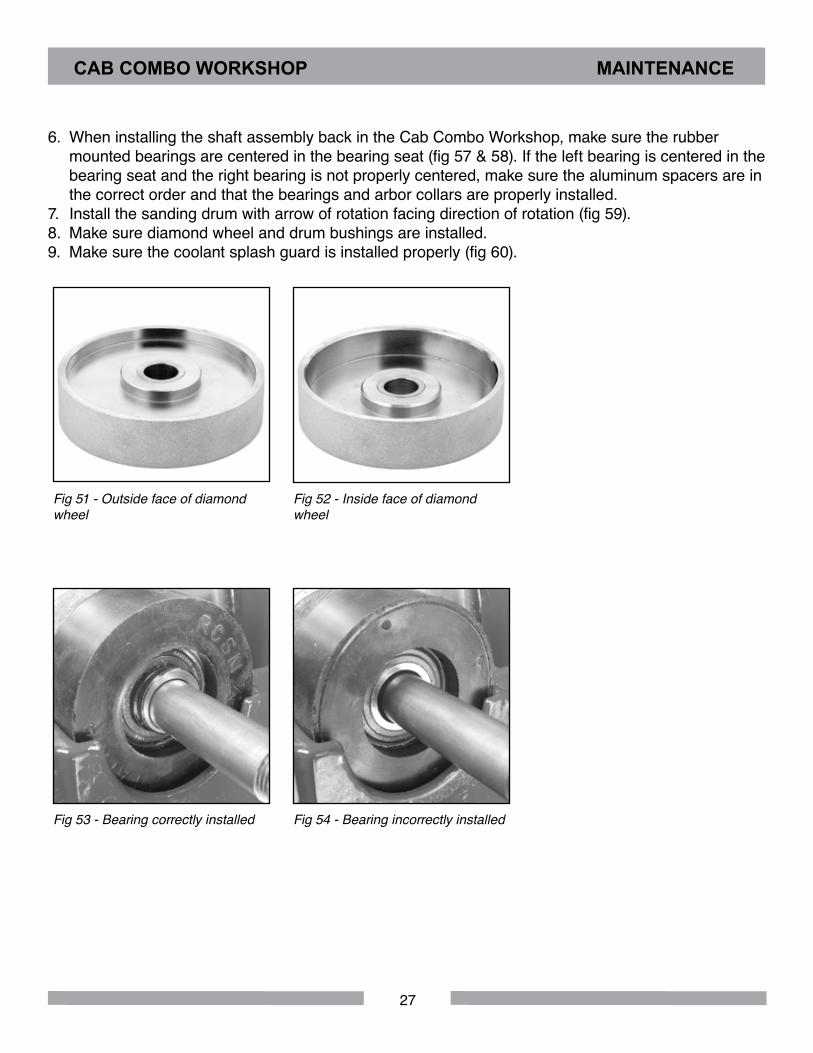
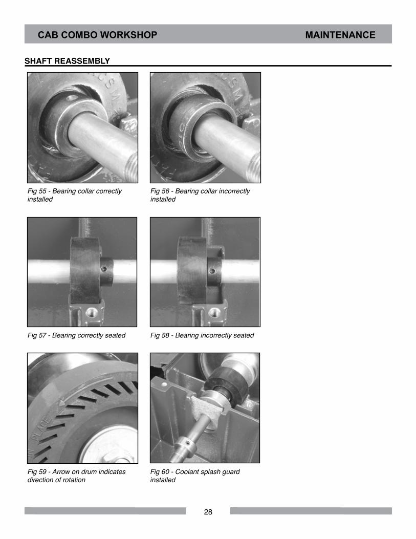
6. When installing the shaft assembly back in the Cab Combo Workshop, make sure the rubber mounted bearings are centered in the bearing seat (fig 57 & 58). If the left bearing is centered in the bearing seat and the right bearing is not properly centered, make sure the aluminum spacers are in the correct order and that the bearings and arbor collars are properly installed.
7. Install the sanding drum with arrow of rotation facing direction of rotation (fig 59). 8. Make sure diamond wheel and drum bushings are installed. 9. Make sure the coolant splash guard is installed properly (fig 60).
Fig 51 - Outside face of diamond wheel
Fig 52 - Inside face of diamond wheel
Fig 53 - Bearing correctly installed Fig 54 - Bearing incorrectly installed
CAB COMBO WORKSHOP MAINTENANCE
28
SHAFT REASSEMBLY
Fig 55 - Bearing collar correctly installed
Fig 56 - Bearing collar incorrectly installed
Fig 57 - Bearing correctly seated Fig 58 - Bearing incorrectly seated
Fig 59 - Arrow on drum indicates direction of rotation
Fig 60 - Coolant splash guard installed
CAB COMBO WORKSHOP MAINTENANCE
29
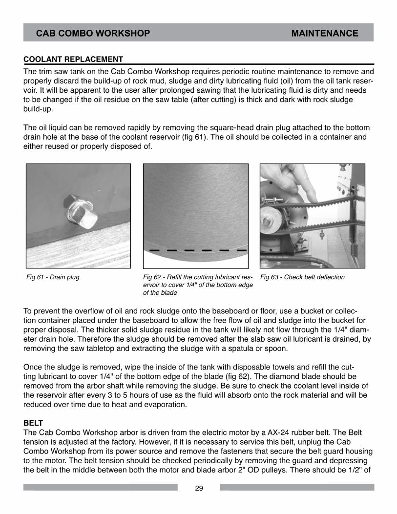
COOLANT REPLACEMENTThe trim saw tank on the Cab Combo Workshop requires periodic routine maintenance to remove and properly discard the build-up of rock mud, sludge and dirty lubricating fluid (oil) from the oil tank reser-voir. It will be apparent to the user after prolonged sawing that the lubricating fluid is dirty and needs to be changed if the oil residue on the saw table (after cutting) is thick and dark with rock sludge build-up.
The oil liquid can be removed rapidly by removing the square-head drain plug attached to the bottom drain hole at the base of the coolant reservoir (fig 61). The oil should be collected in a container and either reused or properly disposed of.
Fig 61 - Drain plug Fig 62 - Refill the cutting lubricant res-ervoir to cover 1/4" of the bottom edge of the blade
Fig 63 - Check belt deflection
To prevent the overflow of oil and rock sludge onto the baseboard or floor, use a bucket or collec-tion container placed under the baseboard to allow the free flow of oil and sludge into the bucket for proper disposal. The thicker solid sludge residue in the tank will likely not flow through the 1/4" diam-eter drain hole. Therefore the sludge should be removed after the slab saw oil lubricant is drained, by removing the saw tabletop and extracting the sludge with a spatula or spoon.
Once the sludge is removed, wipe the inside of the tank with disposable towels and refill the cut-ting lubricant to cover 1/4" of the bottom edge of the blade (fig 62). The diamond blade should be removed from the arbor shaft while removing the sludge. Be sure to check the coolant level inside of the reservoir after every 3 to 5 hours of use as the fluid will absorb onto the rock material and will be reduced over time due to heat and evaporation.
BELTThe Cab Combo Workshop arbor is driven from the electric motor by a AX-24 rubber belt. The Belt tension is adjusted at the factory. However, if it is necessary to service this belt, unplug the Cab Combo Workshop from its power source and remove the fasteners that secure the belt guard housing to the motor. The belt tension should be checked periodically by removing the guard and depressing the belt in the middle between both the motor and blade arbor 2" OD pulleys. There should be 1/2" of
CAB COMBO WORKSHOP MAINTENANCE
30
deflection when the belt is pushed down (fig 63). If the belt tension should become loose, poor sawing performance or slipping will result. If the belt is too tight (i.e. no deflection) the belt, electric motor, pul-leys and blade arbor bearings may wear out prematurely or the motor may overheat and shut off. Belt tension can be adjusted by loosening the two mounting bolts attached to the base of the motor mount and sliding the motor cradle base forward or backward to increase or decrease belt tension. Be sure to adequately retighten the motor mount nuts and replace and attach the belt guard to the table as well.
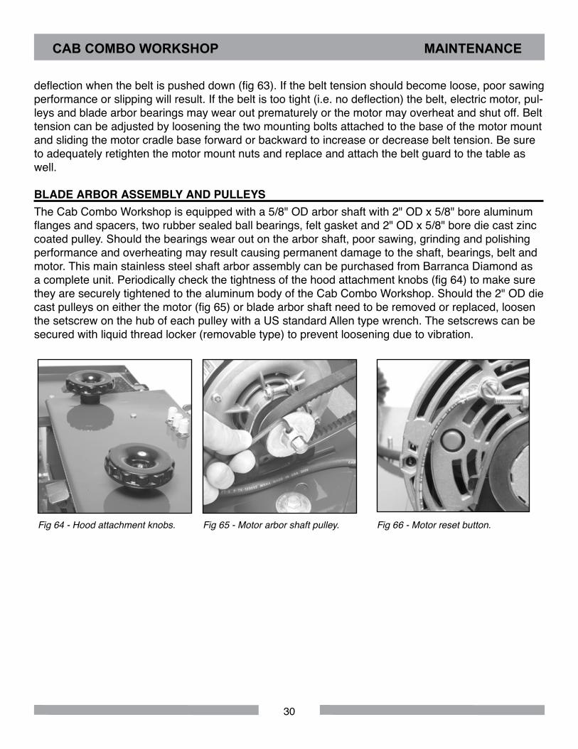
BLADE ARBOR ASSEMBLY AND PULLEYSThe Cab Combo Workshop is equipped with a 5/8" OD arbor shaft with 2" OD x 5/8" bore aluminum flanges and spacers, two rubber sealed ball bearings, felt gasket and 2" OD x 5/8" bore die cast zinc coated pulley. Should the bearings wear out on the arbor shaft, poor sawing, grinding and polishing performance and overheating may result causing permanent damage to the shaft, bearings, belt and motor. This main stainless steel shaft arbor assembly can be purchased from Barranca Diamond as a complete unit. Periodically check the tightness of the hood attachment knobs (fig 64) to make sure they are securely tightened to the aluminum body of the Cab Combo Workshop. Should the 2" OD die cast pulleys on either the motor (fig 65) or blade arbor shaft need to be removed or replaced, loosen the setscrew on the hub of each pulley with a US standard Allen type wrench. The setscrews can be secured with liquid thread locker (removable type) to prevent loosening due to vibration.
Fig 64 - Hood attachment knobs. Fig 65 - Motor arbor shaft pulley. Fig 66 - Motor reset button.
CAB COMBO WORKSHOP MAINTENANCE
31
ELECTRIC MOTORThe Cab Combo Workshop is equipped with a 1/3 HP 1725 RPM single-phase 120 volt 60 Hz 8 amp motor. The motor shaft has sealed ball bearings and requires no lubrication. The motor is protected from thermal damage (overheating) with an automatic shut-off switch. If the motor overheats it will automatically shut off and restart once its internal components cool down and the motor is restarted manually (red button). Be sure to shut off the main motor by placing the switch lever to the OFF posi-tion and disconnecting the power source. After allowing the motor to cool (2 to 3 hours), push the red reset button on the side of the motor (fig. 66) and restart the unit by turning the switch to ON. If the motor does not restart after a cool down period, remove the motor and have an authorized repair ser-vice center inspect the motor. Barranca Diamond can refer you to an authorized motor repair service center in your area.
Please note: On Cab Combo Workshops prior to serial number 850, the motors do not have a reset switch. Therefore it is imperative that if the saw motor should stop during operation that the power to the main motor be shut off by placing the toggle switch in the MIDDLE/OFF position as the motor will restart automatically once cooled down.
DIAMOND BLADEPeriodically, the diamond blade on the Cab Combo Workshop will need to be sharpened or replaced. A dull or “glazed over" diamond blade can stall and cause the motor to shut off and possibly damage the blade or “dish" the core. Once the saw begins to labor or struggle to cut, try using a sharpening stick (green or white silicon carbide material, 60 to 100 grit size) on the blade.
If no sharpening stick is available, use an abrasive material such as cinder block or brick to remove the glazing over the diamonds on the edge of the blade. Do not oversharpen the blade.
Eventually all diamond blades wear out and must be replaced. New continuous rim diamond blades (303 Pro) should be mounted on the blade arbor so that the arrow marked on the steel core is point-ing in the direction of blade rotation. If the arrow cannot be found, use a hand lens or magnifying glass on the blade edge, find the head and tail of any diamond and orient with the tail trailing behind. For notched rim diamond blades (297 or 301 models), it does not matter which way the blade is orien-tated on the arbor shaft.
CAB COMBO WORKSHOP MAINTENANCE
32
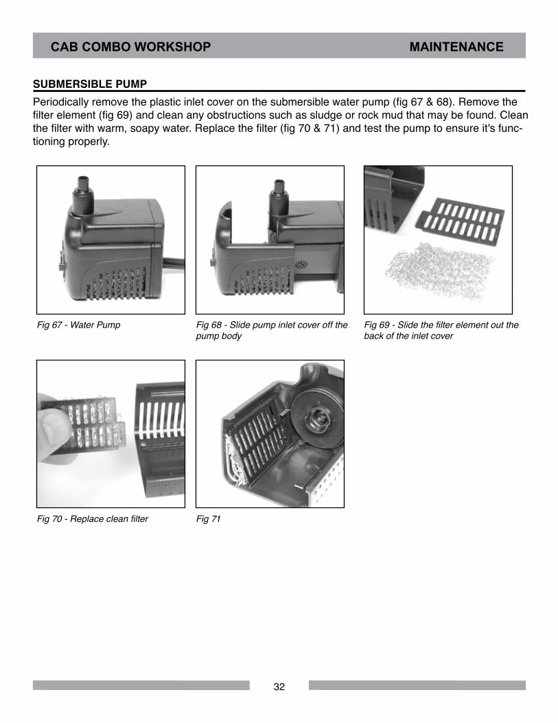
SUBMERSIBLE PUMPPeriodically remove the plastic inlet cover on the submersible water pump (fig 67 & 68). Remove the filter element (fig 69) and clean any obstructions such as sludge or rock mud that may be found. Clean the filter with warm, soapy water. Replace the filter (fig 70 & 71) and test the pump to ensure it's func-tioning properly.
Fig 67 - Water Pump Fig 68 - Slide pump inlet cover off the pump body
Fig 69 - Slide the filter element out the back of the inlet cover
Fig 70 - Replace clean filter Fig 71
CAB COMBO WORKSHOP MAINTENANCE

33
NOTES
34
3
4
6
7
8
9
10
11
12
13
14
16
17
25
26
28
29
30 31
32 33
35
36
38
39
40
41
42
43
44
45
47
51
52
53
54
55
56
57
58
59
60
61
62
63
64
67
68
71
72
74
75
76
77
80
37
15
5
19
20
21
22
23
24
69
78
79
18
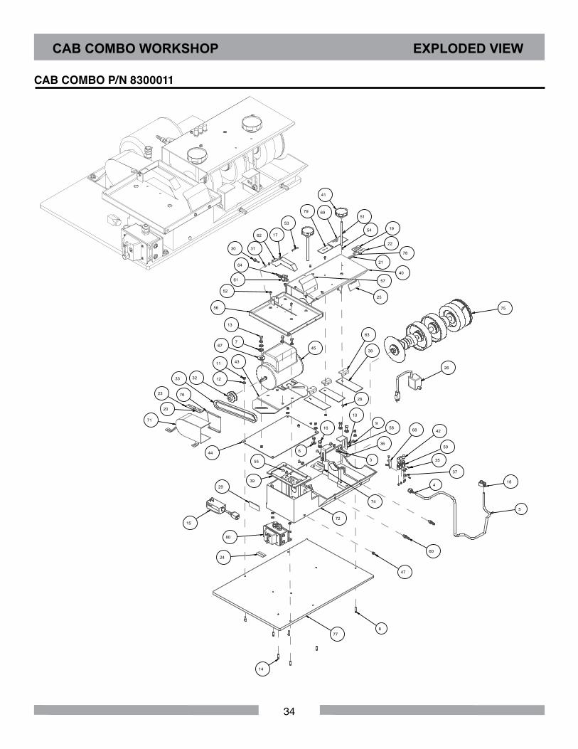
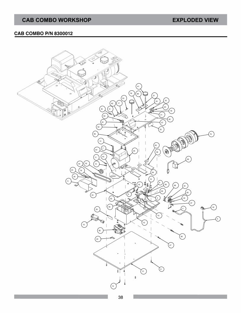
CAB COMBO WORKSHOP EXPLODED VIEW
CAB COMBO P/N 8300011
35
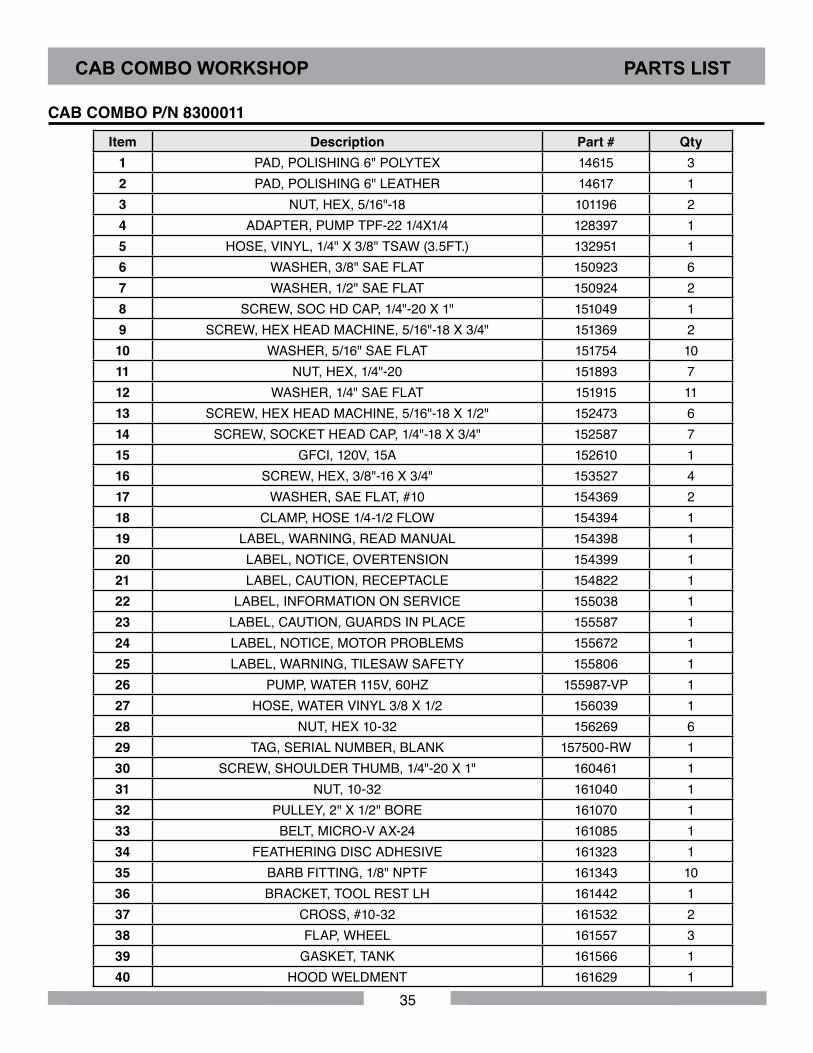
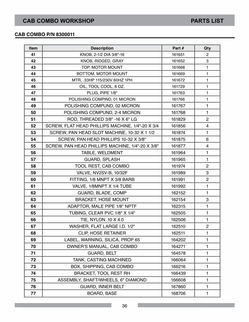
Item Description Part # Qty1 PAD, POLISHING 6" POLYTEX 14615 32 PAD, POLISHING 6" LEATHER 14617 13 NUT, HEX, 5/16"-18 101196 24 ADAPTER, PUMP TPF-22 1/4X1/4 128397 15 HOSE, VINYL, 1/4" X 3/8" TSAW (3.5FT.) 132951 16 WASHER, 3/8" SAE FLAT 150923 67 WASHER, 1/2" SAE FLAT 150924 28 SCREW, SOC HD CAP, 1/4"-20 X 1" 151049 19 SCREW, HEX HEAD MACHINE, 5/16"-18 X 3/4" 151369 210 WASHER, 5/16" SAE FLAT 151754 1011 NUT, HEX, 1/4"-20 151893 712 WASHER, 1/4" SAE FLAT 151915 1113 SCREW, HEX HEAD MACHINE, 5/16"-18 X 1/2" 152473 614 SCREW, SOCKET HEAD CAP, 1/4"-18 X 3/4" 152587 715 GFCI, 120V, 15A 152610 116 SCREW, HEX, 3/8"-16 X 3/4" 153527 417 WASHER, SAE FLAT, #10 154369 218 CLAMP, HOSE 1/4-1/2 FLOW 154394 119 LABEL, WARNING, READ MANUAL 154398 120 LABEL, NOTICE, OVERTENSION 154399 121 LABEL, CAUTION, RECEPTACLE 154822 122 LABEL, INFORMATION ON SERVICE 155038 123 LABEL, CAUTION, GUARDS IN PLACE 155587 124 LABEL, NOTICE, MOTOR PROBLEMS 155672 125 LABEL, WARNING, TILESAW SAFETY 155806 126 PUMP, WATER 115V, 60HZ 155987-VP 127 HOSE, WATER VINYL 3/8 X 1/2 156039 128 NUT, HEX 10-32 156269 629 TAG, SERIAL NUMBER, BLANK 157500-RW 130 SCREW, SHOULDER THUMB, 1/4"-20 X 1" 160461 131 NUT, 10-32 161040 132 PULLEY, 2" X 1/2" BORE 161070 133 BELT, MICRO-V AX-24 161085 134 FEATHERING DISC ADHESIVE 161323 135 BARB FITTING, 1/8" NPTF 161343 1036 BRACKET, TOOL REST LH 161442 137 CROSS, #10-32 161532 238 FLAP, WHEEL 161557 339 GASKET, TANK 161566 140 HOOD WELDMENT 161629 1
CAB COMBO WORKSHOP PARTS LIST
CAB COMBO P/N 8300011
36
Item Description Part # Qty41 KNOB, 2-1/2 DIA 3/8"-16 161651 242 KNOB, RIDGED, GRAY 161652 343 TOP, MOTOR MOUNT 161668 144 BOTTOM, MOTOR MOUNT 161669 145 MTR, .33HP 115/230V 60HZ 1PH 161672 146 OIL, TOOL COOL, 8 OZ. 161729 147 PLUG, PIPE 1/8" 161763 148 POLISHING COMPIND, 01 MICRON 161766 149 POLISHING COMPUND, 02 MICRON 161767 150 POLISHING COMPUND, 2-4 MICRON 161768 151 ROD, THREADED 3/8" -16 X 6" LG 161829 252 SCREW, FLAT HEAD PHILLIPS MACHINE, 1/4"-20 X 3/4 161856 453 SCREW, PAN HEAD SLOT MACHINE, 10-32 X 1 1/2 161874 154 SCREW, PAN HEAD PHILLIPS 10-32 X 3/8" 161875 655 SCREW, PAN HEAD PHILLIPS MACHINE, 1/4"-20 X 3/8" 161877 456 TABLE, WELDMENT 161964 157 GUARD, SPLASH 161965 158 TOOL REST, CAB COMBO 161974 259 VALVE, NV2SV-B, 10/32F 161989 360 FITTING, 1/8 MNPT X 3/8 BARB 161991 261 VALVE, 1/8MNPT X 1/4 TUBE 161992 162 GUARD, BLADE, COMP 162152 163 BRACKET, HOSE MOUNT 162154 364 ADAPTOR, MALE PIPE 1/8" NPTF 162315 165 TUBING, CLEAR PVC 1/8" X 1/4" 162505 166 TIE, NYLON .10 X 4.0 162506 167 WASHER, FLAT LARGE I.D. 1/2" 162510 268 CLIP, HOSE RETAINER 162511 169 LABEL, WARNING, SILICA, PROP 65 164202 170 OWNER'S MANUAL, CAB COMBO 164271 171 GUARD, BELT 164578 172 TANK, CASTING MACHINED 166064 173 BOX, SHIPPING, CAB COMBO 166216 174 BRACKET, TOOL REST RH 166439 175 ASSEMBLY, SHAFT/WHEELS, 6" DIAMOND 166608 176 GUARD, INNER BELT 167860 177 BOARD, BASE 168706 1
CAB COMBO WORKSHOP PARTS LIST
CAB COMBO P/N 8300011

37
Item Description Part # Qty78 LABEL, QR CODE BD MANUALS 171239 179 LABEL, WARNING, PROP 65, EQUIPMENT & COMPONENTS 172641 180 ASSY, SWITCH BOX, 30A, GP 172836-18 181 BELT, 6 X 1.5 DIAMOND 400 MESH 390401 182 BELT, 6 X 1.5 DIAMOND 600 MESH 390601 183 BELT, 6 X 1.5 DIAMOND 1200 MESH 391200 184 BELT, 6 X 1.5 DIAMOND 3000 MESH 393000 1
CAB COMBO WORKSHOP PARTS LIST
CAB COMBO P/N 8300011
38
CAB COMBO WORKSHOP EXPLODED VIEW
3
4
6
7
8
9
10
11
12
13
14
16
17
25
26
28
29
30 31
32 33
35
36
38
39
40
41
42
43
44
45
47
51
52
53
54
55
56
57
58
59
60
61
62
63
64
67
68
71
72
74
75
76
77
80
37
15
5
19
20
21
22
23
24
69
78
79
18
CAB COMBO P/N 8300012
39
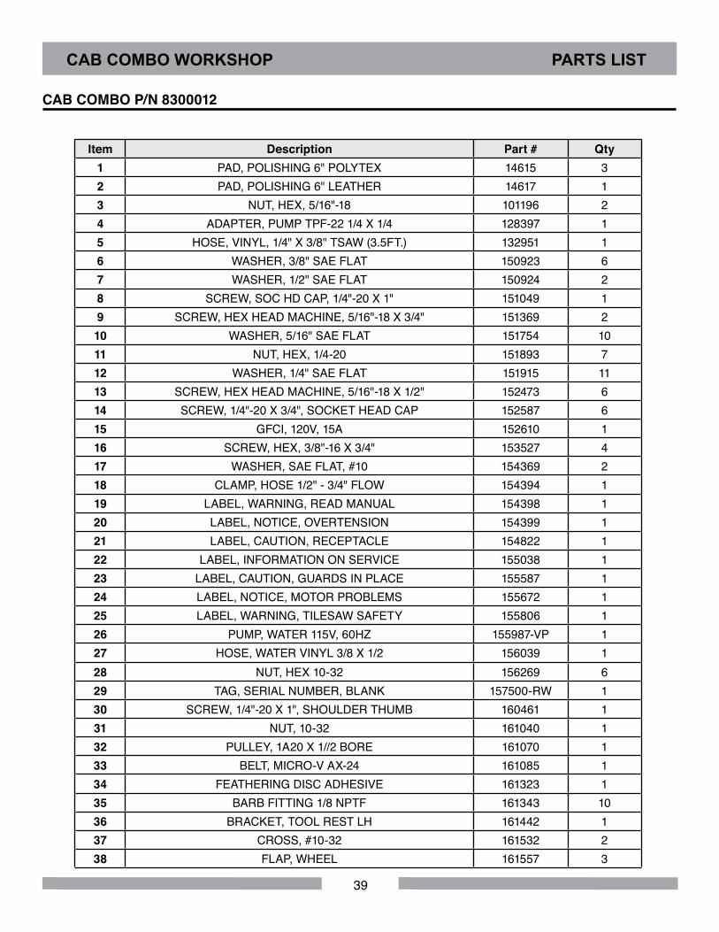
CAB COMBO WORKSHOP PARTS LIST
Item Description Part # Qty1 PAD, POLISHING 6" POLYTEX 14615 32 PAD, POLISHING 6" LEATHER 14617 13 NUT, HEX, 5/16"-18 101196 24 ADAPTER, PUMP TPF-22 1/4 X 1/4 128397 15 HOSE, VINYL, 1/4" X 3/8" TSAW (3.5FT.) 132951 16 WASHER, 3/8" SAE FLAT 150923 67 WASHER, 1/2" SAE FLAT 150924 28 SCREW, SOC HD CAP, 1/4"-20 X 1" 151049 19 SCREW, HEX HEAD MACHINE, 5/16"-18 X 3/4" 151369 210 WASHER, 5/16" SAE FLAT 151754 1011 NUT, HEX, 1/4-20 151893 712 WASHER, 1/4" SAE FLAT 151915 1113 SCREW, HEX HEAD MACHINE, 5/16"-18 X 1/2" 152473 614 SCREW, 1/4"-20 X 3/4", SOCKET HEAD CAP 152587 615 GFCI, 120V, 15A 152610 116 SCREW, HEX, 3/8"-16 X 3/4" 153527 417 WASHER, SAE FLAT, #10 154369 218 CLAMP, HOSE 1/2" - 3/4" FLOW 154394 119 LABEL, WARNING, READ MANUAL 154398 120 LABEL, NOTICE, OVERTENSION 154399 121 LABEL, CAUTION, RECEPTACLE 154822 122 LABEL, INFORMATION ON SERVICE 155038 123 LABEL, CAUTION, GUARDS IN PLACE 155587 124 LABEL, NOTICE, MOTOR PROBLEMS 155672 125 LABEL, WARNING, TILESAW SAFETY 155806 126 PUMP, WATER 115V, 60HZ 155987-VP 127 HOSE, WATER VINYL 3/8 X 1/2 156039 128 NUT, HEX 10-32 156269 629 TAG, SERIAL NUMBER, BLANK 157500-RW 130 SCREW, 1/4"-20 X 1", SHOULDER THUMB 160461 131 NUT, 10-32 161040 132 PULLEY, 1A20 X 1//2 BORE 161070 133 BELT, MICRO-V AX-24 161085 134 FEATHERING DISC ADHESIVE 161323 135 BARB FITTING 1/8 NPTF 161343 1036 BRACKET, TOOL REST LH 161442 137 CROSS, #10-32 161532 238 FLAP, WHEEL 161557 3
CAB COMBO P/N 8300012

40
CAB COMBO WORKSHOP PARTS LIST
CAB COMBO P/N 8300012
39 GASKET, TANK 161566 140 HOOD WELDMENT 161629 141 KNOB, 2-1/2 DIA X 3/8-16 161651 242 KNOB, RIDGED, GRAY 161652 343 TOP, MOTOR MOUNT 161668 144 BOTTOM, MOTOR MOUNT 161669 145 MTR, .33HP 115/230V 60HZ 1PH 161672 146 OIL, TOOL COOL, 8 OZ. 161729 147 PLUG, PIPE 1/8" 161763 148 POLISHING COMPOUND, 01 MICRON 161766 149 POLISHING COMPOUND, 02 MICRON 161767 150 POLISHING COMPOUND, 2-4 MICRON 161768 151 ROD, THREADED 3/8-16 X 6"LG. 161829 252 SCREW, 1/4-20 X 3/4 FLAT HEAD PHILLIPS MACHINE 161856 453 SCREW, 10-32 X 1-1/2 PAN HEAD SLOT MACHINE 161874 154 SCREW, PAN HEAD PHILLIPS 10-32 X 3/8" 161875 655 SCREW, 1/4-20 X 3/8 PAN HEAD PHILLIPS MACHINE 161877 456 TABLE, WELDMENT 161964 157 GUARD, SPLASH 161965 158 TOOL REST, CAB COMBO 161974 259 VALVE, NV2SV-B, 10/32F 161989 360 FITTING, 1/8 MNPT X 3/8 BARB 161991 261 VALVE, 1/8NPTFM X 1/4 TUBE 161992 162 GUARD, BLADE, COMP 162152 163 BRACKET, HOSE MOUNT 162154 364 ADAPTOR, MALE PIPE 1/8 NPTF 162315 165 TUBING, CLEAR PVC, 1/8 X 1/4 (36") 162505 166 TIE, NYLON .10 X 4.0 162505 167 WASHER, FLAT LARGE I.D. 1/2" 162510 268 CLIP, HOSE RETAINER 162511 169 LABEL, WARNING, SILICA, PROP 65 164202 170 OWNER'S MANUAL, CAB COMBO 164271 171 GUARD, BELT 164578 172 TANK, CASTING MACHINED 166064 173 BOX, SHIPPING, CAB COMBO 166216 174 BRACKET, TOOL REST RH 166439 175 ASSY, SHAFT/WHEELS, 6" DIAMOND 166608 1
41
CAB COMBO WORKSHOP PARTS LIST
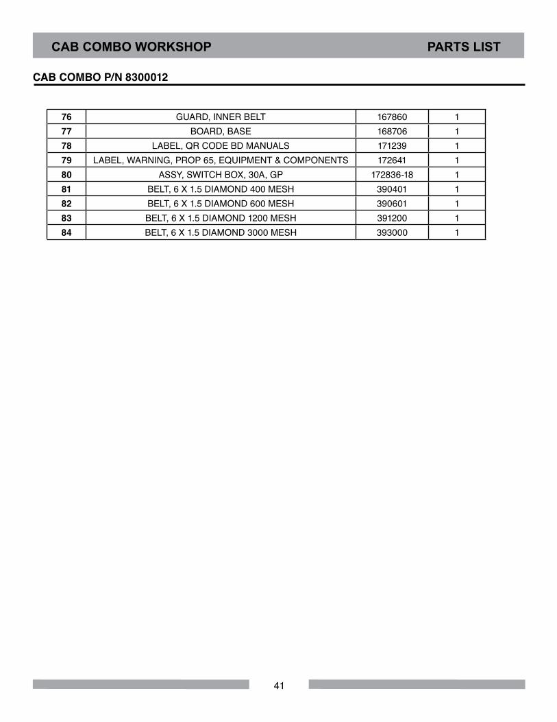
CAB COMBO P/N 8300012
76 GUARD, INNER BELT 167860 177 BOARD, BASE 168706 178 LABEL, QR CODE BD MANUALS 171239 179 LABEL, WARNING, PROP 65, EQUIPMENT & COMPONENTS 172641 180 ASSY, SWITCH BOX, 30A, GP 172836-18 181 BELT, 6 X 1.5 DIAMOND 400 MESH 390401 182 BELT, 6 X 1.5 DIAMOND 600 MESH 390601 183 BELT, 6 X 1.5 DIAMOND 1200 MESH 391200 184 BELT, 6 X 1.5 DIAMOND 3000 MESH 393000 1
42
CAB COMBO WORKSHOP PARTS LIST
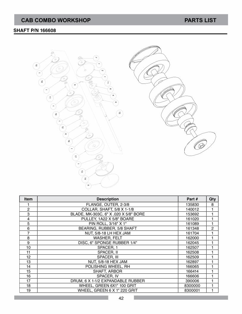
Item Description Part # Qty1 FLANGE, OUTER, 2-3/8 135830 82 COLLAR, SHAFT, 5/8 X 1-1/8 140012 13 BLADE, MK-303C, 6" X .020 X 5/8" BORE 153692 14 PULLEY, 1A22 X 5/8" BOARE 161020 15 PIN ROLL, 3/16" X 1" 161089 16 BEARING, RUBBER, 5/8 SHAFT 161348 27 NUT, 5/8-18 LH HEX JAM 161704 18 WASHER, FELT 162000 19 DISC, 6" SPONGE RUBBER 1/4" 162045 1
10 SPACER, 1 162507 111 SPACER, II 162508 112 SPACER, III 162509 113 NUT, 5/8-18 HEX JAM 162897 114 POLISHING WHEEL, RH 166065 115 SHAFT, ARBOR 166414 116 SPACER, IV 166606 117 DRUM, 6 X 1-1/2 EXPANDABLE RUBBER 390006 118 WHEEL, GREEN 6X1" 100 GRIT 8300000 119 WHEEL, GREEN 6 X 1" 220 GRIT 8300001 1
SHAFT P/N 166608
8
18
19
5
1
2
***
4
6
7
10
11
12
13 14
15
16
17
1
1
1
1
1
6
1
1
9

43
NOTES
44
CAB COMBO WORKSHOP WARRANTY
Barranca Diamond warrants to the original retail purchaser for a period of 90 days except as noted, from the date of purchase all products covered by this Warranty to be free of defects in materials and workmanship.
This Warranty shall not apply to any parts that have been subjected to misuse or improper service, that had been damaged in transit or handling, or that have been altered or repaired by unauthorized representatives. This Warranty does not cover defects caused by or resulting from misuse, abuse, ne-glect or damage caused by accident or the failure to provide reasonable maintenance. This Warranty is void if the product or any of its individual components is altered or modified by the purchaser or if the product is used in a manner or with a blade not recommended by the manufacturer.
Any claim arising under this Warranty must be submitted by the original purchaser within the warranty period specified above, and shall include proof of purchase. During said warranty period Barranca Diamond shall, at its option, either replace or repair, at no charge to the original purchaser, any parts or components that are found to be defective by Barranca Diamond. Barranca Diamond shall not be responsible for or obligated to pay for freight or other transportation related costs or expenses in con-nection with any defective products or components that are either returned to Barranca Diamond’s facility or any authorized repair station and/or any replacement products or components that are shipped from Barranca Diamond pursuant to this Warranty.
Parts and labor needed to maintain products and the replacement of components due to normal wear and tear are the purchaser’s responsibility and are not covered by this Warranty. All products or components replaced under warranty become the property of the manufacturer. All replacement parts will be considered to be part of the original product and any warranty on such parts will expire coincidentally with the original Warranty. Barranca Diamond will pay for parts and labor in connection with warranty repairs conducted by Barranca Diamond or its authorized repair centers. Replacement part(s) installed by anyone else will be provided without a charge for such replacement part(s), but this Warranty will not apply to labor charges in connection therewith.
IN NO EVENT SHALL ANY LIABILITY UNDER THIS WARRANTY EXCEED THE REPLACEMENT COST OF ANY DEFECTIVE PRODUCT OR COMPONENT THEREOF, AND BARRANCA DIAMOND SHALL NOT BE LIABLE FOR ANY INCIDENTAL OR CONSEQUENTIAL DAMAGES OR FOR ANY OTHER DAMAGE OR LOSS NOT EXPRESSLY ASSUMED AS SET FORTH HEREIN.The foregoing constitutes an expressed warranty on the terms set forth above and is the only warran-ty or warranties applicable to the products it covers. All other warranties, including, without limitation, the implied warranty of merchantability and/or fitness for a particular purpose or use being denied. This limited warranty is expressly in lieu of all other warranties, whether expressed or implied.
BARRANCA DIAMOND LIMITED WARRANTYPlease complete the warranty registration card and return. Any problems encountered should be di-rected to Barranca Diamond Customer Service department at (800) 630-7682 M-F 8am - 5pm PST.
WARRANTY: For your (1) one year warranty to be effective, complete the online Product Registration as soon as possible. Visit www.mkdiamond.com/registration/
45
Specifics Applicable to Limited Warranty of Diamond Blades and Core Bits:
Laser Welded Blade and Bit Warranty: If the laser weld between the segment and the steel core or barrel fails during normal use, the blade or bit will be replaced free of charge. Blades and bits damaged due to careless or improper use are not covered under this warranty.
Brazed Blade, Bit, and Cup Wheel Warranty:If the brazed bond between the segment and the core, barrel, or cup fails within the first .050 of seg-ment wear, the blade, bit, or cup will be replaced free of charge. Blades, bits, and cup wheels dam-aged due to careless or improper use are not covered under this warranty.
Continuous Rim Blade Warranty: If the bond between the rim and the core fails during normal use, the blade will be replaced free of charge. Blades and bits damaged due to careless or improper use are not covered under this war-ranty.
Exclusions:Barranca Diamond does not warrant the following components, which carry their own manufacturer’s warranty for the indicated periods:
Electric Motors Manufacturer’s Warranty Baldor: 1 yearRyobi: 1 YearSoga: 1 Year
Gas Engines Manufacturer’s WarrantyHonda: 2 years
Engine Power InformationEngine power ratings are calculated by the individual engine manufacturer and the rating method may vary among engine manufacturers. Barranca Diamond Products makes no claim, representation or Warranty as to the power rating of the engine on this equipment and disclaims any responsibility or liability of any kind whatsoever with respect to the accuracy or the engine power rating. Users are advised to consult the engine manufacturer’s owners manual and website for specific information regarding the engine power rating.
CAB COMBO WORKSHOP WARRANTY
46
CAB COMBO WORKSHOP WARRANTY
REPLACEMENT PARTSReplacement parts for this tool may be ordered from your Barranca Diamond distributor or directly from Barranca Diamond. Please have the following information ready before calling:• Model and serial number of the machine• Date of purchase• Description of parts being ordered (see parts list)
RETURN MATERIALS PROCEDURETo expedite the service relative to the return of a product purchased through Barranca Diamond, please have the following information available:• Model and serial number of the machine• Date of purchase• Distributor’s name
Then please call Barranca Diamond at (310) 523-5867 or toll free at 800-630-7682 to obtain a Return Goods Authorization number (RGA) authorizing the return.
Please Note:• Ensure your item(s) are prepaid to the destination• Return items must have been purchased within the previous twelve (12) months• Follow the packaging instructions in the following section• Be sure to include the RGA number, return address and your phone number on or within the return shipping box.
PACKAGING INSTRUCTIONSShip the equipment using its original shipping crate if possible. Secure inside the shipping crate. Ensure all parts are secured in the packaging to prevent movement. Do not ship the equipment partially exposed.

47
NOTES

CAB COMBO WORKSHOPOWNER'S MANUAL
& PARTS LIST
Barranca Diamond Products, Inc.1315 Storm ParkwayTorrance, CA 90501
Toll-Free: (800) 421-5830Phone: (310) 539-5221
Fax: (310) 539-5158www.barrancadiamond.com