Embed Size (px)
Citation preview

Metal Removal from Effluents by Electrowinning and a new Design Conceptin Wastewater Purification Technology
V. StankoviæDepartment of Metallurgical Engineering; Technical Faculty Bor;VJ 12 19210 Bor; University of Belgrade; SerbiaE-mail: [email protected]
In recent years there has been an increased interest in finding new and innovativesolutions for efficient metal removal from effluents. Electrowinning has particularly beenconsidered as a way for efficient solution of the water and soil pollution problems. Elec-trochemical cells, designed to operate with effluents at low concentrations, require spe-cial provisions for enhancement of mass transport to the electrode surface. Different con-cepts for doing this are critically reviewed. The various types of cells are described andcompared and some advantages and disadvantages are discussed. Particular attention hasbeen paid to those effluents not suitable to be treated by the electrowinning method.Pertraction as an emerging technology, suitable for separating and concentrating heavymetal ions from very dilute solutions is described and considered as a way to be coupledwith electrowinning for heavy metal removal. The proposed process offers many advan-tages over the existing technologies for cleaning wastewater from heavy metals. A com-prehensive literature survey of the electrochemical reactors as well as of supported liquidmembrane technique is also given.
Key words:Electrowinning, electrochemical cell, three-dimensional electrode, effluent treatment,pertraction, heavy metals
Introduction
Every year, millions of tons of different haz-ardous waste are generated all over the world. Dueto inefficient waste handling techniques and wasteleakage in the past, thousands of sites, as well asgroundwater are polluted by heavy metals or otherhazardous materials, damaging the ecosystem.
Consequently, in the last third of the past cen-tury significant breakthrough was achieved in es-tablishing new processes for reclaiming metal fromvarious liquors and effluents. The increasing con-cern for environmental protection became the cru-cial factor for further development of industrial pro-cesses. Several new and innovative solutions for ef-ficient contaminant removal have been investigatedand it is strongly believed that they will help insolving the problem of water and soil pollution.Yet, despite numerous promising laboratory experi-ments, there are not many successful implementa-tions.
All those processes, developed and marketed inthat period, or still under development, could begrouped as:
– Solvent extraction/stripping processes, in-cluding complexation of targeted ions from the ef-fluent by an extractant and decomposition of the
formed metal-organic complex by a proper strip-ping solution.
– Sorption processes that include either physi-cal adsorption on an adsorbent or chemi-sorption byion exchange resins.
– Membrane processes that include selectiveion transfer across membranes under a pressure- orconcentration-difference as the driving force, orwith an applied potential difference in case ofelectrodialytic processes. Liquid membranes, sup-ported by a carrier, have particularly been consid-ered in this matter as a very powerful separationand concentration technique.
– Electrochemical processes that include theelectrowinning of metal ions from effluents.
Excluding the direct electrowinning processthat can remove metal ions from an effluent in onestep, all other processes consist of three mainstages:
1. Separation stage – in which some targetedions are being removed from an effluent by aproper mediator (extractant, adsorbent, membrane);
2. Concentration stage – including stripping(desorption or re-extraction) of removed ions froma mediator and their concentration in a stripping so-lution;
V. STANKOVIÆ, Metal Removal from Effluents by Electrowinning and a new Design …, Chem. Biochem. Eng. Q. 21 (1) 33–45 (2007) 33
ReviewReceived: October 31, 2006
Accepted: December 13, 2006
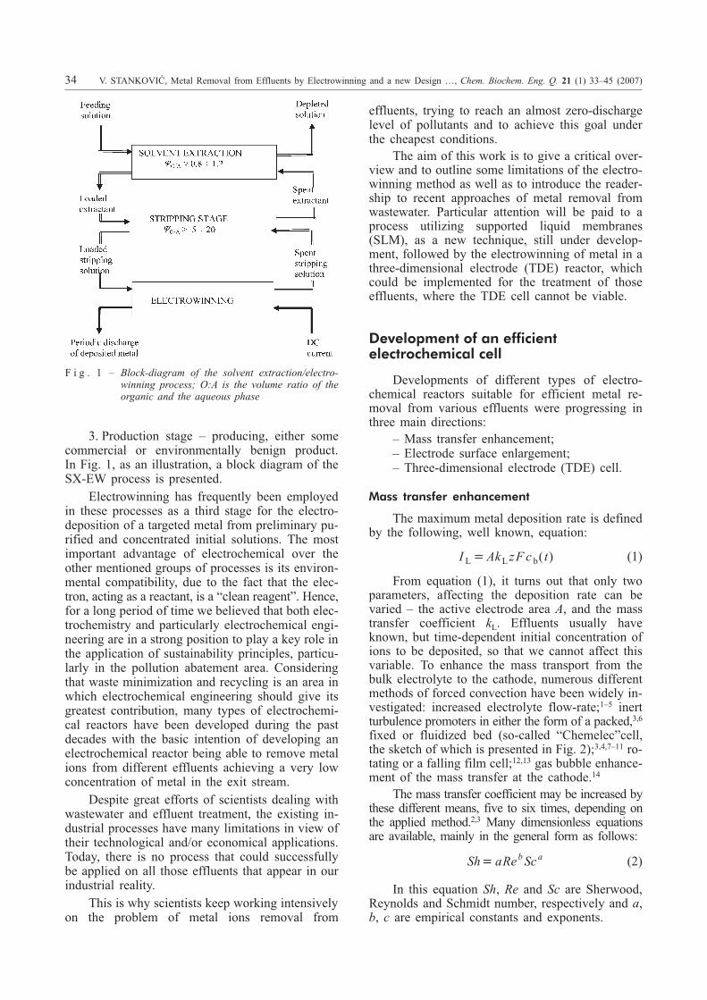
3. Production stage – producing, either somecommercial or environmentally benign product.In Fig. 1, as an illustration, a block diagram of theSX-EW process is presented.
Electrowinning has frequently been employedin these processes as a third stage for the electro-deposition of a targeted metal from preliminary pu-rified and concentrated initial solutions. The mostimportant advantage of electrochemical over theother mentioned groups of processes is its environ-mental compatibility, due to the fact that the elec-tron, acting as a reactant, is a “clean reagent”. Hence,for a long period of time we believed that both elec-trochemistry and particularly electrochemical engi-neering are in a strong position to play a key role inthe application of sustainability principles, particu-larly in the pollution abatement area. Consideringthat waste minimization and recycling is an area inwhich electrochemical engineering should give itsgreatest contribution, many types of electrochemi-cal reactors have been developed during the pastdecades with the basic intention of developing anelectrochemical reactor being able to remove metalions from different effluents achieving a very lowconcentration of metal in the exit stream.
Despite great efforts of scientists dealing withwastewater and effluent treatment, the existing in-dustrial processes have many limitations in view oftheir technological and/or economical applications.Today, there is no process that could successfullybe applied on all those effluents that appear in ourindustrial reality.
This is why scientists keep working intensivelyon the problem of metal ions removal from
effluents, trying to reach an almost zero-dischargelevel of pollutants and to achieve this goal underthe cheapest conditions.
The aim of this work is to give a critical over-view and to outline some limitations of the electro-winning method as well as to introduce the reader-ship to recent approaches of metal removal fromwastewater. Particular attention will be paid to aprocess utilizing supported liquid membranes(SLM), as a new technique, still under develop-ment, followed by the electrowinning of metal in athree-dimensional electrode (TDE) reactor, whichcould be implemented for the treatment of thoseeffluents, where the TDE cell cannot be viable.
Development of an efficientelectrochemical cell
Developments of different types of electro-chemical reactors suitable for efficient metal re-moval from various effluents were progressing inthree main directions:
– Mass transfer enhancement;– Electrode surface enlargement;– Three-dimensional electrode (TDE) cell.
Mass transfer enhancement
The maximum metal deposition rate is definedby the following, well known, equation:
I Ak zF c tL L b� ( ) (1)
From equation (1), it turns out that only twoparameters, affecting the deposition rate can bevaried – the active electrode area A, and the masstransfer coefficient kL. Effluents usually haveknown, but time-dependent initial concentration ofions to be deposited, so that we cannot affect thisvariable. To enhance the mass transport from thebulk electrolyte to the cathode, numerous differentmethods of forced convection have been widely in-vestigated: increased electrolyte flow-rate;1–5 inertturbulence promoters in either the form of a packed,3,6
fixed or fluidized bed (so-called “Chemelec”cell,the sketch of which is presented in Fig. 2);3,4,7–11 ro-tating or a falling film cell;12,13 gas bubble enhance-ment of the mass transfer at the cathode.14
The mass transfer coefficient may be increased bythese different means, five to six times, depending onthe applied method.2,3 Many dimensionless equationsare available, mainly in the general form as follows:
Sh a Scb a� Re (2)
In this equation Sh, Re and Sc are Sherwood,Reynolds and Schmidt number, respectively and a,b, c are empirical constants and exponents.
34 V. STANKOVIÆ, Metal Removal from Effluents by Electrowinning and a new Design …, Chem. Biochem. Eng. Q. 21 (1) 33–45 (2007)
F i g . 1 – Block-diagram of the solvent extraction/electro-winning process; O:A is the volume ratio of theorganic and the aqueous phase

Explicit forms of equation (2), for an estima-tion of the mass transfer coefficient, for differentelectrochemical systems and electrode arrange-ments, are given in relevant literature.3,4,15
Specific electrode surface area enlargement
A very important feature of any electrolyticcell is the space-time yield as a measure of cell pro-ductivity per unit of installed cell volume and time.Starting from Faraday’s law and, introducing equa-tion (1), it can be expressed as:
1
V
m
tak M c
d
d e L b�+ * (3)
Where: �e is the current efficiency; � = j/jL – ratiobetween operating and limiting current density; a =A/V – specific surface area (cathode surface per unitof cell volume); kL – mass transfer coefficient; M –molar mass; cb – concentration of metal ions in thebulk. Keeping the other variables constant, the cellproductivity increases proportionally to the specificsurface area a. Going in this direction many newtypes of cells appeared as: Swiss-roll cell1,3 sche-matically presented in Fig.3a, capillary-gap cell;1,4
filter press cell (see Fig. 3b);3,15 etc., having consid-erably higher electrode surface per unit of volumethan a conventional cell, as presented in Table 1.
V. STANKOVIÆ, Metal Removal from Effluents by Electrowinning and a new Design …, Chem. Biochem. Eng. Q. 21 (1) 33–45 (2007) 35
F i g . 2 – Sketch of (a) Chemelec cell and the (b) ECO cell12
F i g . 3 – Sketch of (a) Swiss-roll1 and (b) filter press cell3
T a b l e 1 – Specific surface area and space-time yield ofsome particular cells16
Type of cellSpecific surface
aream–1
Space-time yieldmol m–3 h–1
Conventional cell 7.5 0.14
Filter press cell 30 – 170 0.56 – 3.17
Capillary gap cell 100 – 500 1.9 – 9.33
TDE – fixed bed cell 1000 – 10 000 18.65 – 186.5
TDE – fluidized bed cell 1000 – 10 000 37.3 – 186.5
TDE – rotating drum cell 50 – 5000 9.32 – 93.3
Three-dimensional electrode (TDE) cell
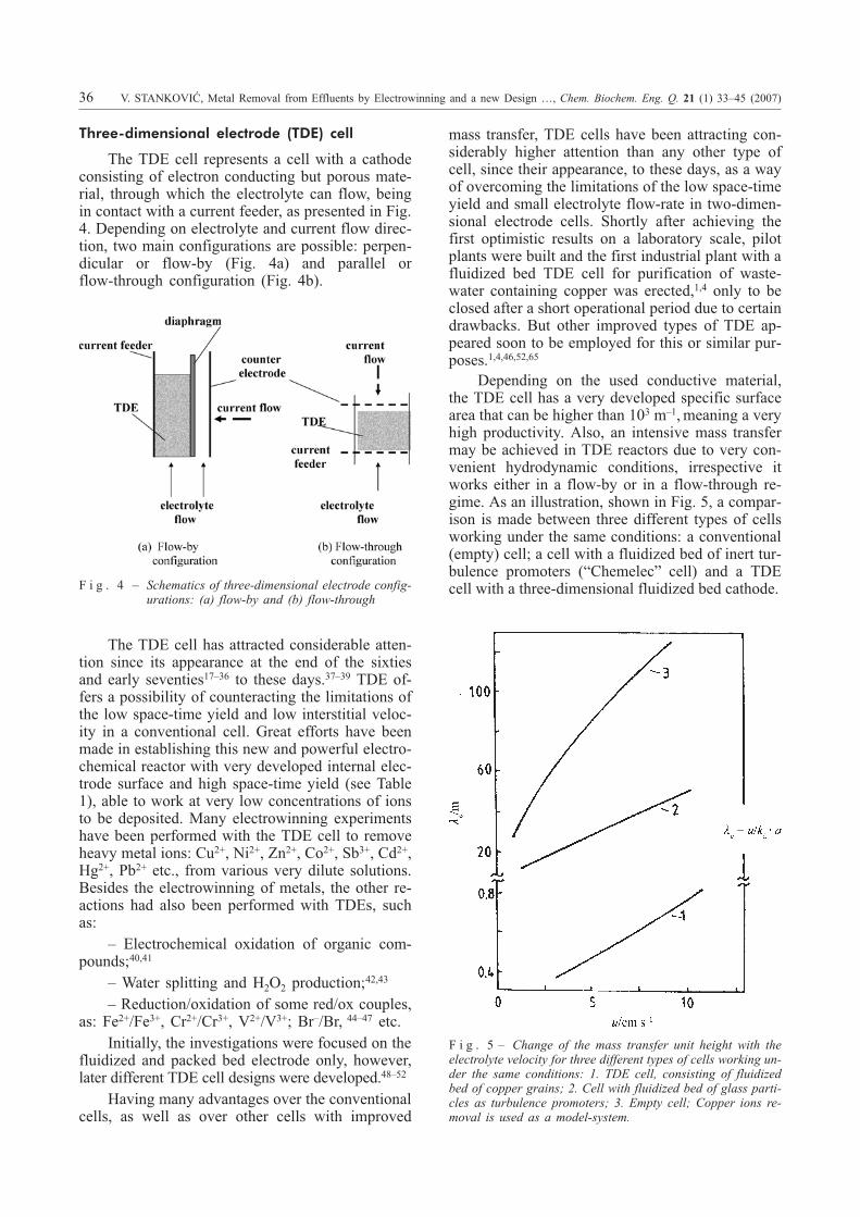
The TDE cell represents a cell with a cathodeconsisting of electron conducting but porous mate-rial, through which the electrolyte can flow, beingin contact with a current feeder, as presented in Fig.4. Depending on electrolyte and current flow direc-tion, two main configurations are possible: perpen-dicular or flow-by (Fig. 4a) and parallel orflow-through configuration (Fig. 4b).
The TDE cell has attracted considerable atten-tion since its appearance at the end of the sixtiesand early seventies17–36 to these days.37–39 TDE of-fers a possibility of counteracting the limitations ofthe low space-time yield and low interstitial veloc-ity in a conventional cell. Great efforts have beenmade in establishing this new and powerful electro-chemical reactor with very developed internal elec-trode surface and high space-time yield (see Table1), able to work at very low concentrations of ionsto be deposited. Many electrowinning experimentshave been performed with the TDE cell to removeheavy metal ions: Cu2+, Ni2+, Zn2+, Co2+, Sb3+, Cd2+,Hg2+, Pb2+ etc., from various very dilute solutions.Besides the electrowinning of metals, the other re-actions had also been performed with TDEs, suchas:
– Electrochemical oxidation of organic com-pounds;40,41
– Water splitting and H2O2 production;42,43
– Reduction/oxidation of some red/ox couples,as: Fe2+/Fe3+, Cr2+/Cr3+, V2+/V3+; Br–/Br, 44–47 etc.
Initially, the investigations were focused on thefluidized and packed bed electrode only, however,later different TDE cell designs were developed.48–52
Having many advantages over the conventionalcells, as well as over other cells with improved
mass transfer, TDE cells have been attracting con-siderably higher attention than any other type ofcell, since their appearance, to these days, as a wayof overcoming the limitations of the low space-timeyield and small electrolyte flow-rate in two-dimen-sional electrode cells. Shortly after achieving thefirst optimistic results on a laboratory scale, pilotplants were built and the first industrial plant with afluidized bed TDE cell for purification of waste-water containing copper was erected,1,4 only to beclosed after a short operational period due to certaindrawbacks. But other improved types of TDE ap-peared soon to be employed for this or similar pur-poses.1,4,46,52,65
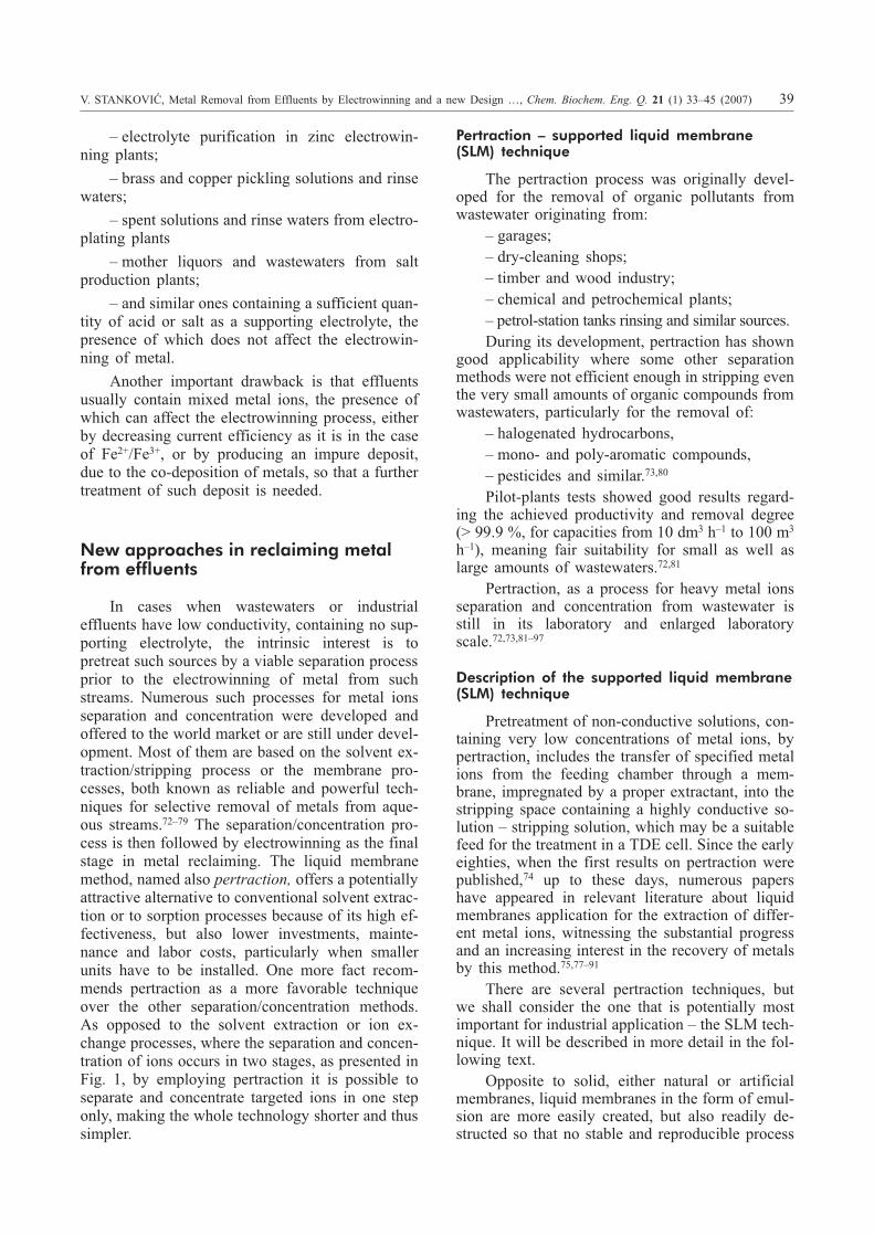
Depending on the used conductive material,the TDE cell has a very developed specific surfacearea that can be higher than 103 m–1,meaning a veryhigh productivity. Also, an intensive mass transfermay be achieved in TDE reactors due to very con-venient hydrodynamic conditions, irrespective itworks either in a flow-by or in a flow-through re-gime. As an illustration, shown in Fig. 5, a compar-ison is made between three different types of cellsworking under the same conditions: a conventional(empty) cell; a cell with a fluidized bed of inert tur-bulence promoters (“Chemelec” cell) and a TDEcell with a three-dimensional fluidized bed cathode.
36 V. STANKOVIÆ, Metal Removal from Effluents by Electrowinning and a new Design …, Chem. Biochem. Eng. Q. 21 (1) 33–45 (2007)
F i g . 4 – Schematics of three-dimensional electrode config-urations: (a) flow-by and (b) flow-through
F i g . 5 – Change of the mass transfer unit height with theelectrolyte velocity for three different types of cells working un-der the same conditions: 1. TDE cell, consisting of fluidizedbed of copper grains; 2. Cell with fluidized bed of glass parti-cles as turbulence promoters; 3. Empty cell; Copper ions re-moval is used as a model-system.

A comparison is made in view of the masstransfer unit height �e, as a measure of valuation ofeach type of cell – to obtain an insight as to howmany times the TDE cell is favorable in this regardcompared to the other two cells. The mass transferunit height �e represents a characteristic electrodelength at which the difference between an inlet ciand outlet co concentration is equal to the meandriving force of the electrowinning process, i.e.:
c c
ci � �0 1, av
�e is here defined by the following term:
-eL
�u
k a(5)
where: u is an actual electrolyte velocity inside theinter-electrode space.
Obviously, the mass transfer unit height �e inthe TDE cell is for one order of magnitude less thanin a cell with inert turbulence promoters, and even120 – 150 times shorter than in an empty cell. Thatmeans it is possible to achieve the same conversionof a reactant, equal to one unit of mass transfer, in aTDE cell having of 0.5 m in length, and in anempty cell, which is approximately 90 m long andof equal other two dimensions.
Therefore, an enormously high formal geomet-rical current density (j = 102 – 104 A m–2) may beachieved in the TDE cell depending on the workingconditions, while the real current density (calcu-lated on the whole available TDE surface), remainsrather low. It is therefore possible to treat very di-lute solutions (less than . =1 g dm–3 of an initialmass concentration) in TDE cells, achieving a finalfraction w < 1 · 10–6 in the outlet stream.1,4,65 Themetal yield, as well as the current efficiency in theTDE cell is also very high.20,21,49,67 Further, the TDEcell is suitable to work either in a batch or in a sin-gle pass mode which is a particularly positive TDEcell quality, as well.
On a pilot-plant or on an industrial scale theTDE cell demonstrated to possess numerous andvery serious disadvantages, not observed or perhapsneglected on a laboratory scale. One of the most se-rious drawbacks is the potential profile within theelectrode making some parts of the electrode moreand some others less active. Consequences that ap-pear are that some parts of the electrode are moreand some others are less- or even inactive. More-over, some parts are polarized oppositely, leading toreversing in an overall current efficiency and metalyield.68–70 This part of energy can be sacrificed incases when the removal of metal is important, as inthe electrowinning of noble- or very hazardous met-
als, as for example Hg, Cd, Pb and some others –less toxic but pollutants in any case. Lower reactionyield and worse selectivity (less important for metalwinning, but highly important in electro-organicsynthesis, for example) may be expected in a TDEcell having an expressed potential profile within theelectrode thickness. To minimize this shortcoming,small electrode thickness (a few centimeters only)may be used. This can only be efficient on a labora-tory or enlarged laboratory scale. Keeping the elec-trode thickness at a small value of 2 – 5 cm and ex-tending as a compensation of the electrode surfacein the two other dimensions by one or two orders ofmagnitude will cause many operating problems.Some of these problems are summarized and pre-sented in Table 2, for two types of TDE cell: for thefixed bed electrode cell, and the fluidized bed elec-trode cell.
For both parallel and perpendicular configura-tion of TDE, consisting of a porous or disperse con-ductive material, the deposition of metal onto theelectrode surface may significantly reduce the voidfraction of the TDE, causing a permanent but pro-gressive obstruction of the electrolyte flow throughthe TDE with time.49,71 This obstruction of the elec-trolyte flow may achieve enormously high valuesafter a longer period of metal deposition and, in theextreme case, the deposited metal may completelyblock the electrolyte flow, stopping the process en-tirely.35,71 Thus, for TDE cell design, the depositioncycle has to be particularly considered and opti-mized depending on the used cathode material andits porosity. This especially relates to a granular
V. STANKOVIÆ, Metal Removal from Effluents by Electrowinning and a new Design …, Chem. Biochem. Eng. Q. 21 (1) 33–45 (2007) 37
T a b l e 2 – Drawbacks of the TDE cell
Packed bed electrode Fluidized bed electrode
• Unpredictable hydrodynamics.
• Non-uniform velocityprofile – thus non-uniformmass transfer within theelectrode.
• Pressure drop increasesdue to a local bed porosityreduction with time.
• Deposited metal penetratesinto the diaphragm if itexists.
• Channeling may occurinside the bed at higher cellheight due to a badelectrolyte distribution.
• Agglomeration of bedparticles will appear due tothe metal deposition.
• Working electrolyteflow-rate has to be keptclose to a minimumfluidization velocity toobtain lower bed resistivity.
• In practice, it is difficult toachieve particulatefluidization in a narrow bedin which the two otherdimensions are much largerthan the bed thickness.
• Channeling through the bedmay occur causing theagglomeration of particlesin dead zones.
• Short lifetime of thediaphragm should beexpected, due to itserosion.

cathode material having the porosity around thevalue of 0.4. It was observed that metal depositionoccurs more intensively in those parts of the TDEwhere the reaction rate is faster due to higher elec-trode activity. For rectangular electrode geometry,corners are more active due to a better mass transferin those parts. Due to higher electrode potential, theparts closer to the counter electrode are more activethan those close to the current feeder as shown inFig. 6, in accordance with the results of Simsic etal.71
In those electrowinning processes, in whichhydrogen evolution is a simultaneous cathode reac-tion, there is an increase in specific energy con-sumption due to a gas hold-up inside the electrode,causing an elevated cell voltage. The gas bubblesgenerated within the electrode obstruct the electro-lyte flow, causing a greater pressure-drop in theTDE cell as presented in Fig. 7.56,57 The relativepressure-drop, defined here as a ratio between anactual pressure-drop ,p, with gas bubbles in theelectrode and the pressure-drop in the absence ofgas bubbles, po is presented vs. time for differentelectrolyte flow-rates. It is clear that the presence ofa gas phase inside a TDE significantly increases therelative pressure-drop in the fixed bed, while in thefluidized bed the relative pressure-drop ,p/ po isslightly lower than unity. The elevated pressure-dropwill increase the pumping energy and this effect willinfluence increased specific energy consumption.
Role of the supporting electrolyte
In general, the major limitation of the direct elec-trowinning process to be widely implemented formetal removal from effluents, is the precondition thateffluents to be processed must contain sufficientlyhigh conductivity; that means enough supporting elec-trolyte, preserving the cell work at an acceptably lowcell voltage – thus at a reasonably low specific energyconsumption. Deficiency of a supporting electrolyteand a small amount of ions to be removed from an ef-
fluent may significantly increasethe influence of ion migration onthe mechanism of ions transportto the electrode but, more im-portantly, it will cause a highohmic-voltage drop, transform-ing almost the whole introducedelectric-energy to heat energy.Treatment of effluents with nosupporting electrolyte and withvery low concentration of ionsto be deposited in a TDE cellwill cause a high cell voltageand low current efficiency in-creasing dramatically the spe-cific energy consumption. Insuch circumstances, the cell willoperate far from its optimal con-ditions making the process ofelectrowinning more expensivethan it should be.
This disadvantage signifi-cantly restricts the implementa-tion of the TDE cell, directingit towards those effluents al-ready having a high conductiv-ity, as it is in:
38 V. STANKOVIÆ, Metal Removal from Effluents by Electrowinning and a new Design …, Chem. Biochem. Eng. Q. 21 (1) 33–45 (2007)
F i g . 6 – Schematics of metal deposition front in a three-di-mensional carbon felt cathode according to71;Copper deposition is used as a model-system.
F i g . 7 – Relative pressure-drop behavior with time for different electrolyte velocities56
– electrolyte purification in zinc electrowin-ning plants;
– brass and copper pickling solutions and rinsewaters;
– spent solutions and rinse waters from electro-plating plants
– mother liquors and wastewaters from saltproduction plants;
– and similar ones containing a sufficient quan-tity of acid or salt as a supporting electrolyte, thepresence of which does not affect the electrowin-ning of metal.
Another important drawback is that effluentsusually contain mixed metal ions, the presence ofwhich can affect the electrowinning process, eitherby decreasing current efficiency as it is in the caseof Fe2+/Fe3+, or by producing an impure deposit,due to the co-deposition of metals, so that a furthertreatment of such deposit is needed.
New approaches in reclaiming metalfrom effluents
In cases when wastewaters or industrialeffluents have low conductivity, containing no sup-porting electrolyte, the intrinsic interest is topretreat such sources by a viable separation processprior to the electrowinning of metal from suchstreams. Numerous such processes for metal ionsseparation and concentration were developed andoffered to the world market or are still under devel-opment. Most of them are based on the solvent ex-traction/stripping process or the membrane pro-cesses, both known as reliable and powerful tech-niques for selective removal of metals from aque-ous streams.72–79 The separation/concentration pro-cess is then followed by electrowinning as the finalstage in metal reclaiming. The liquid membranemethod, named also pertraction, offers a potentiallyattractive alternative to conventional solvent extrac-tion or to sorption processes because of its high ef-fectiveness, but also lower investments, mainte-nance and labor costs, particularly when smallerunits have to be installed. One more fact recom-mends pertraction as a more favorable techniqueover the other separation/concentration methods.As opposed to the solvent extraction or ion ex-change processes, where the separation and concen-tration of ions occurs in two stages, as presented inFig. 1, by employing pertraction it is possible toseparate and concentrate targeted ions in one steponly, making the whole technology shorter and thussimpler.
Pertraction – supported liquid membrane(SLM) technique
The pertraction process was originally devel-oped for the removal of organic pollutants fromwastewater originating from:
– garages;– dry-cleaning shops;– timber and wood industry;– chemical and petrochemical plants;– petrol-station tanks rinsing and similar sources.During its development, pertraction has shown
good applicability where some other separationmethods were not efficient enough in stripping eventhe very small amounts of organic compounds fromwastewaters, particularly for the removal of:
– halogenated hydrocarbons,– mono- and poly-aromatic compounds,– pesticides and similar.73,80
Pilot-plants tests showed good results regard-ing the achieved productivity and removal degree(> 99.9 %, for capacities from 10 dm3 h–1 to 100 m3
h–1), meaning fair suitability for small as well aslarge amounts of wastewaters.72,81
Pertraction, as a process for heavy metal ionsseparation and concentration from wastewater isstill in its laboratory and enlarged laboratoryscale.72,73,81–97
Description of the supported liquid membrane(SLM) technique
Pretreatment of non-conductive solutions, con-taining very low concentrations of metal ions, bypertraction, includes the transfer of specified metalions from the feeding chamber through a mem-brane, impregnated by a proper extractant, into thestripping space containing a highly conductive so-lution – stripping solution, which may be a suitablefeed for the treatment in a TDE cell. Since the earlyeighties, when the first results on pertraction werepublished,74 up to these days, numerous papershave appeared in relevant literature about liquidmembranes application for the extraction of differ-ent metal ions, witnessing the substantial progressand an increasing interest in the recovery of metalsby this method.75,77–91
There are several pertraction techniques, butwe shall consider the one that is potentially mostimportant for industrial application – the SLM tech-nique. It will be described in more detail in the fol-lowing text.
Opposite to solid, either natural or artificialmembranes, liquid membranes in the form of emul-sion are more easily created, but also readily de-structed so that no stable and reproducible process
V. STANKOVIÆ, Metal Removal from Effluents by Electrowinning and a new Design …, Chem. Biochem. Eng. Q. 21 (1) 33–45 (2007) 39

can be achieved.72,81 A major drawback in using theliquid membrane technology lies in the fact that theformed emulsion must be destroyed in order to re-trieve the stripping phase and then it must be re-formed for reuse. This means several steps have tobe introduced in the technology chain, making thewhole process very complex, more expensive, andthus not competitive to other separation processes.Great progress has been made in stabilization of athin liquid film of extractant on solid porous syn-thetic polymer membranes, called supported liquidmembranes (SLM), which would act selectively to-wards some particular ion. The geometric form ofthe micro-porous support that is mostly used in thisresearch, may be either (a) flat, or (b) cylindrical(hollow fibers bundle placed in a cylindrical shell),as shown in Fig. 8.
Flat geometry seems more convenient to becoupled with a TDE cell, but it has rather modestspecific surface (not exceeding 100 m2 m–3, calcu-lated on the feeding chamber volume). A muchmore developed surface may be acquired by usingcylindrical geometry, the specific surface of whichmay exceed 1 · 10–3 m–1.73,93,94 As a membrane ma-terial, different porous synthetic polymer materialsare used, as: polysulfone; polypropylene; polyeth-ylene; polyacrylonitrile, polyurethane; regeneratedcellulose and so on. The impregnation is usually
carried out by dipping the solid porous membraneinto an appropriate extractant dissolved in an or-ganic solvent immiscible with water, making theimpregnated membrane hydrophobic. The poreswill be filled with the extractant (denoted as blackspots on the details given in Fig. 7). After drainingthe surplus of organic out of the surface and rinsingthe membrane with water, it is ready for ion trans-portation across. Particular attention has to be paidto choosing the proper extractant for impregnation.It has to be able to complex some particular ionsfrom the aqueous phase and be indifferent againstthe others present in the aqueous phase. Features ofcommercial extractants – their selectivity and ex-traction ability against metal ions are known, sothat careful screening and the choice of the mostappropriate amongst them is a very complex taskand must be considered for each effluent separately.There are so many extractants and their correspond-ing solvents available on the market, known undertheir commercial names.90 There are even muchmore other organic compounds, making a novelgeneration of potential extractants still under re-search and development, possessing the ability tocomplex some particular ions and a reader isreferred to numerous literature concerning tometal-organic complexes formation.
Stoichiometry and ion-transfer mechanismacross the SLM
The stoichiometry of metal ion complexationin the solvent extraction process may, in manycases, be presented by the following stoichiometricequation:
Me HL MeL Ha az
zz z� �� � �0 0, (6)
Where: HL – is the extractant molecule; MeLz – ismetal-organic complex. Subscripts a and o, denotethe aqueous and the organic phase, respectively.
From eq. (6), it comes out that the pH of theaqueous phase decreases during the process. Bychanging the pH value the extraction equilibriumcan be shifted toward complex formation or its de-composition.
The mechanism of ion transport across SLM isillustrated in Fig. 9.
The ions to be extracted, coming in contactwith the impregnated membrane, will be complexedby the captured extractant and immobilized onto themembrane surface. The concentration of ions at thewater/membrane interface will drop and the flux ofmetal ions from the bulk, through the boundarylayer, toward the interface will be established.Metal-organic molecules MeLz, at the interface, dif-fuse across the membrane toward its stripping side,
40 V. STANKOVIÆ, Metal Removal from Effluents by Electrowinning and a new Design …, Chem. Biochem. Eng. Q. 21 (1) 33–45 (2007)
F i g . 8 – Schematic view of SLM contactor geometries,partly according to ref.72: Flat configuration – left; Hollow fi-bers module – right; F – feeding side; S – membrane; R –stripping side

where they come in contact with a stripping solu-tion containing an excessive amount of H+ ions(usually between � = 200 – 300 g dm–3 of acid). Be-cause of the MeLz complex instability in strongacidic media, it will be decomposed in contact withthe stripping solution at the membrane/stripping so-lution interface, forming again metal ion and releas-ing the ligand molecule HL, enabling it to be re-used, according to the reverse equation:
MeLz,0 + zHa� = Mea
z� + z HL0 (7)
Metal ions Mez+, formed on the stripping sideand leaving the membrane surface through theboundary layer on the stripping side, will be trans-ported by convection toward the bulk of the strip-ping solution, while the renewed extractant HL willdiffuse back through the membrane toward thefeeding solution interface. In such a way, two equalbut countercurrent molecular fluxes across themembrane are formed, as shown in Fig. 9. At asteady-state condition, all fluxes become equal,leading to an overall flux, which may be describedby the following simple equation:
J K c cz zMe Me Mea e� �� �( ) (8)
where: JMe - is metal flux (mol m–2s–1); K – masstransport coefficient, m s–1; and c cz zMe Mea e
� �, – con-centration of metal ions in the feeding solution andat the equilibrium in mol m–3, respectively.
Mass transport coefficient K, for hollow fibersmembranes, is defined by the following equation:
1 1 1 1
0 0 0K r kmk
r
rr k
i
i i� � �
m ln(9)
Where: ki and k0 is the mass transfer coefficient onthe inner and outer side of the membrane wall, re-spectively; ri and r0 inner and outer radius of the fi-bers, respectively; m is the distribution coefficient
of extracted metal; km mass transfer coefficientacross the membrane. K strongly depends on manyvariables, such as: solid membrane thickness, meanpore size, membrane porosity, physical propertiesand concentration of captured extractant, hydrody-namic conditions on both the feeding and strippingside, and some others. Many, mainly dimensionlessrelationships are recommended in relevant litera-ture.73,76,81,86 Usually, the kinetics of complex for-mation is not the limiting step of the process butdiffusion across the membrane.95
For SLM systems operating in a batchrecirculation mode, it is easy to prove that the massflux will depend on time as well as on the concen-tration of metal ions. Based on mass balance, anequation for the cylindrical SLM geometry, as wellas for the condition that the equilibrium concentra-tion is much lower than the actual one, the follow-ing concentration – time relationship may be de-rived:95
c t cQ
VK tMe Me i( ) exp,� � �
�
��
!" (10)
where: cMe,i, cMe(t) – is an initial and actual concen-tration of metal ions, respectively; Q – flow-rate ofthe aqueous phase through the feeding space of theSLM module (m3 s–1); V – volume of the feedingspace (m3); t – process time (s). According to equa-tion (10), an exponential decrease of metal ion con-centration in the feeding solution should be ex-pected, as shown in Fig. 10.
As one can see, starting from an initial concen-tration of copper ions of w = 250 · 10–6 in water, anextraction degree higher than 96 % is achievedmeaning that the final concentration, upon pertrac-tion is less than 10 · 10–6. By them, the feeding so-
V. STANKOVIÆ, Metal Removal from Effluents by Electrowinning and a new Design …, Chem. Biochem. Eng. Q. 21 (1) 33–45 (2007) 41
F i g . 9 – Schematics of the ion transport mechanism acrossthe SLM wall
F i g . 1 0 – Change of the dimensionless concentration (leftaxis) and the extraction degree (right axis) vs. time – effect ofthe feeding solution flow-rate; Copper ions removal is used asa model-system: w = 250 10–6; pH 2.

lution volume flow-rate, higher than 0.7 dm3 min–1,does not affect the pertraction rate, indicating thatthe limiting step is diffusion of the formedmetal-organic complex across the membrane. Forfurther depletion of residual metal from raffinate,an additional stage of pertraction has to be installed.The number of steps as a matter of process optimi-zation will not be considered here.
There are not so many published data about thestripping kinetics and factors affecting it. Resultspublished recently show that the mass concentra-tion of acid above � = 300 g dm–3 in the strippingsolution does not affect the stripping degree.90 De-pending on the feeding and stripping volume ratio –�F/S, the mass concentration of metal in the strip-ping solution usually is in the range of 2 to 5g dm–3. Such a solution, containing an excessiveamount of supporting electrolyte, is a very goodfeed for a TDE cell or “Chemelec cell”, for exam-ple. The results on the stripping process of copperremoved from a wastewater by the SLM techniqueare partly given below. The final mass concentra-tion of metal in the stripping solution, strongly de-pends on the �F/S volume ratio and should be amatter of process optimization.
Very small flow-rates may be applied throughthe hollow fibers bundle, due to their small innerdiameter, used in these experiments.97
Advantages and disadvantagesof membrane contactors
The basic advantage of the SLM technique isthat it offers an adequately complete extraction ofmetals, toxic or valuable, but it also separates andconcentrates targeted ions in a form of solution suit-able for electrowinning. The SLM, considered as anew and prospective separation technique, hasmany advantages over the other conventional sepa-ration technologies, such as:
– lower investment costs;– low energy consumption;– ability to separate only targeted ionic species
from mixed solutions;– high separation ratio;
– high concentration factor;– low extractant inventory;– SLM contactors have no moving parts;– they have a known and constant interfacial
area during the process;– SLMs possess a substantially higher mass
transfer unit height than other dispersive contactorsused for the same purpose;
– scale-up is more straightforward with mem-brane contactors;
Due to all these reasons, pertraction is consid-ered an attractive technology, particularly suitablefor the removal of hazardous metals from industrialwastewater.
On the downside, SLM contactors also havesome disadvantages that may be summarized as fol-lows:
– the impregnated membrane introduces fairlyhigh resistance to mass transfer;
– on a larger scale, membrane contactors aresubject to shell side bypassing, which results in anefficiency loss;
– membranes are subject to fouling as a prob-lem with pressure-driven devices;
– the achievable number of equilibrium stagesis limited by pressure-drop constraints;
– the lifetime of membranes is finite and theirperiodical replacing needs to be considered.
All above ranked good features of the SLMcontactor, put against its drawbacks, make this tech-nique attractive enough to be investigated as ametal extractor from wastewater.
Evaluation of the SLM/Electrowinning Process
Applying the SLM technique, it is possible toseparate targeted ionic species from non-conductivewastewater and to concentrate it in the strippingstream, the acidity of which is high enough to be effi-ciently treated in a TDE- or some other type of elec-trochemical cell. Choosing the volume ratio betweenthe feeding and the stripping solution, it is possible todirect with the concentration of metal ions in the exitstream, achieving the most appropriate one, good fortreating in a TDE cell. Moreover, having a strippingsolution containing acid as a supporting electrolyteand single ionic species, will guarantee a smooth andefficient electrowinning process, resulting in a puremetal deposit. High current efficiency may beachieved and kept constant during the electrowinning.
The TDE cell, coupled with the SLM techniqueas a pretreating step, may efficiently work reclaimingmetals from all those effluents that could not betreated by direct electrowinning. A two-staged processis established and schematically presented in Fig. 11.
42 V. STANKOVIÆ, Metal Removal from Effluents by Electrowinning and a new Design …, Chem. Biochem. Eng. Q. 21 (1) 33–45 (2007)
T a b l e 3 – Data on the stripping of copper in the SLM pro-cess95
Volumeratio�F/S
Concentrationof H2SO4c/mol dm–3
Stripping solutionflow-rateQs/cm
3 s–1
Mass concentrationof Cu2+
�/gdm–3
25
25
2
3
0.028
0.055
3.25
3.55

The feeding solution, containing miscellaneousions, is being introduced in the pertraction step.Passing through the feeding space of the SLM mod-ule, the extraction of some targeted ion occurs. Thedepleted feeding solution (raffinate) leaves themodule, to be recycled or released in a recipient.Metal ions, complexed by an extractant in the mem-brane pores, are transferred across the membranetoward the stripping side. The stripping solution,the volume of which is much smaller than the vol-ume of the feeding solution will destroy themetal-organic complex, and metal ions will be con-centrated. The volume ratio �F/S and the strippingflow-rate are such, to ensure a desired concentrationof metal in the stripping stream entering into theelectrowinning step. Upon electrowinning, the de-pleted stripping solution flows back into thepertraction stage to be loaded again by a new por-tion of metal, making a closed loop. The depositedmetal will be discharged periodically. This way, bycoupling the SLM technique with electrowinning, asimple and efficient, two-staged process is estab-lished for treatment of effluents containing valuableor hazardous metal ions from wastewaters.
Besides the advantages listed earlier, some ad-ditional ones were observed during the experimen-tal work and considerations on how to integrate theSLM technique into the electrowinning technology.These advantages could be summarized as:
– very low concentration in raffinate could beachieved in the pertraction step;
– very high metal yield and energy efficiencyis achieved;
– very suitable technology for treating very di-lute solutions;
– there is no membrane saturation and no waterrinsing problem as in the case of ion-exchange col-umns;
– poisoning of the module does not exist as inthe case of ion-exchange resin column processes;
– no entrainment of extractant as in the case ofconventional solvent extraction processes.
Indeed, each of these advantages gives goodreason to carry on further investigations toward es-tablishing this new process.
Conclusions
Cells with three-dimensional electrodes em-body a potentially powerful electrochemical reactorhaving a very low mass transfer unit height, andthus very high productivity compared to the othertypes of cells.
There are many drawbacks, rather of the chem-ical engineering than of electrochemical nature, thathave to be considered and resolved in order toachieve an optimal TDE cell design. New, highlyporous electrode materials are now available on themarket that will prolong the metal deposition cycleand to ensure stable hydrodynamic conditionswithin the electrode.
The main deficiency for wider implementationof the TDE cell – treatment of dilute non-conduc-tive effluents, may be resolved by coupling theTDE cell with the SLM contactor, to pre-treat sucheffluents prior to electrowinning.
The proposed process exhibits many advantagesover the conventional extraction or sorption pro-cesses, as for example conventional solvent extrac-tion or the ion-exchange resin process. The majoradvantage may be that it consists of two steps only.
To facilitate its commercialization, challengesthat need to be addressed include several problemsstill unresolved:
– In the pertraction step, the stripping processhas to be improved in view of faster kineticsachievement, by optimizing the hydrodynamic con-ditions on the stripping side.
– At countercurrent flow of the feeding andstripping solution, pressures on both sides must bekept equal; to avoid penetration either of the feed-ing or stripping solution into membrane pores,squeezing the extractant out of them.
– Another weakness is the membrane disrup-tion, and mixing of the feeding and stripping solu-tions with each other.
This is rather a question of membrane materialquality that will be resolved by improving its me-chanical features, but also by improving the processcontrol, which has to be fully automated.
V. STANKOVIÆ, Metal Removal from Effluents by Electrowinning and a new Design …, Chem. Biochem. Eng. Q. 21 (1) 33–45 (2007) 43
F i g . 1 1 – Block diagram of the SLM – TDE process formetal removal from wastewaters

L i s t o f s y m b o l s
A – surface area, m2
a – specific area, m2 m–3
c – concentration, mol dm–3
F – Faraday constant, C mol–1
I – current, mAj – current densityki, k0 – mass transfer coefficient of inner and outer side,
m s–1
kL – mass transfer coefficient, m s–1
M – molar mass, g mol–1
m – mass, gp – pressure drop, M PaQ – volume flow rate, dm3 min–1
r – radius, mt – time, minV – volume, m3
w – mass fraction, 10–6
z – ion charge number� – mass concentration, g dm–3
�e – current efficiency� – volume ratio, VF; VS
R e f e r e n c e s
1. Juettner, K., Galla U., Schmeider, H., Electrochim. Acta45 (2000) 2575.
2. Stankoviæ, V., J. Applied Electrochem. 20 (1990)3. Coeuret, F., Storck, A, Elements de Genie Chimique,
TEC&DOC, Paris, France, 1984.4. Wendt, H., Kreysa, G., Electrochemical Engineering,
Springer Verlag, Berlin, Germany, 1999.5. Justinijanoviæ, I., Stankoviæ, Z., Stankoviæ, V., Zlatkoviæ, V.,
Kem. Ind. 1 (1) (1978) 7.6. Isaacson, M. S., Sonin, A. A., Ind. Eng. Chem., Proc.
Des.&Dev. 15 (1976) 313.7. Carbin, D. C., Gabe, D. R., Electrochim. Acta 19 (1974)
645.8. Carbin, D. C., Gabe, D. R., J. Applied Electrochem. 5
(1975) 137.9. Le Goff, P., Vergnes, F., Coeuret, F., Bordet, F., Ind. Eng.
Chem. Proc. Des.&Dev. 61 (1969) 8.10. Storck, A., Coeuret, F., Electrochim. Acta 26 (1981) 127.11. Walker, A. T. S., Wragg, A. A., Electrochim. Acta 25 (1980)
323.12. Gabe, D. R., Walsh, F., J. Applied Electrochem. 13 (1983)
3.13. Coeuret, F., Legrand, J., J. Applied Electrochem. 15 (1985)
18114. Sedahmed, G. H., J. Applied Electrochem. 14 (1984) 693.15. Carlsson, L., Sandergen, B., Simonsson, D., Rihovsky, M.,
J. Electrochem. Soc. 130 (1983) 342.16. Backhurst, J. R., Ph. D. Thesis, University of Newcastle
upon Tyne, 1967.17. Backhurst, J. R., Coulson, J. M. Goodridge, F., Tenna-
koon, L., J. Electrochem. Soc. 116 (1969) 1600.18. Fleischmann, M., Oldfield, J. W., Electroanalytical Chem-
istry and Interfacial Electrochemistry, 29 (1971) 211.19. Flett, D. S., Chemistry and Industry, March 51 (1971) 300.
20. Wilkinson, J. A. F., Haines, K. P., Trans. Inst. Min. Metal-lurgy, Section C, 81 (1972) 157.
21. Kuhn, A. T., Houghton, R. W., J. Appl. Electrochem. 4(1974) 69.
22. Pickett, J. D., J. Appl. Electrochem. 5 (1975) 101.23. Kreysa, G., Pionteck, S., Heitz, E., J. Appl. Electrochem.
5 (1975) 305.24. Kreysa, G., Chem. Ing. Tech. 50 (1978) 332.25. Coeuret, F., Electrochimica Acta 21 (1976) 185.26. Coeuret, F., Electrochimica Acta 21 (1976) 203.27. Sabacky, J., Evans, J. W., J. Electrochem. Soc. 126 (1979)
1180.28. Simpson, C. C., J. Metals 29 (1977) 6.29. Sherwood, W. G., Queneau, P. B., Nikoliæ, C., Hodges,
D. R., Metallurgical Transaction B, 10B (1979) 659.30. Coeuret, F., J. Appl. Electrochem. 10 (1980) 687 (and ref-
erences therein).31. Jiricny, V., Evans, J. W., Metallurgical Transaction B, 15B
(1984) 623.32. Cooper, W. C., J. Appl. Electrochem. 15 (1985) 789 (and
literature cited therein).33. Stankoviæ, V. D., Janes, D., IchemE Symposium Series
No. 98 (1986) 247.34. Stankoviæ, V.D., Lazareviæ, G., Wragg, A. A., J. Appl.
Electrochem. 25 (1995) 864.35. Scott, K., J. Appl. Electrochem. 18 (1988) 504.36. Rajeshwar, K., Ibanez, J. G., Swain, G. M., J. Appl.
Electrochem. 24 (1994) 1077 (and references therein).37. Njau, K. N., van der Woude, M. E., Rutgers-van der Steen,
K., Koene, L., Janssen, L. J. J., IchemE Symposium SeriesNo. 145 (2002) 161.
38. Friedrich, J. M., Ponce-de-Leon, C., Reade, G. W., Walsh,F. C., J. Electroan. Chem. 561 (2004) 203 (and referencestherein).
39. Brown, C. J., Pletcher, D., Walsh, F. C., Hammond, J. K.,Robinson, D., J. Appl. Electrochem. 24 (1994) 95.
40. Tennakoon, C. L. K., Bharwaj, R. C., Bockris, J. O’M., J.Appl. Electrochem. 26 (1996) 18.
41. Ponce de Leon, C., Pletcher, D., J. Appl. Electrochem. 25(1995) 307.
42. Alvarez-Gallegos, A., Pletcher, D., Electrochimica Acta 44(1998) 853.
43. Kelsall, G. H., House, C. I., Gudyanga, F. P., J. Electro-anal. Chem. 224 (1988) 179.
44. House, C. I., Kelsall, G. H., Int. Conf. on “ExtractionMetallurgy ’85” London, UK, Sept. (1985); Proceedings,p.p. 659–682
45. Kelsall, G. H., Robinson, D. J., IchemE Symp. Series No.112 (1989) 277.
46. Van Velzen, D., Langenkamp, H., Schuetz, G., Lalonde, D.,Flamm, J., Fiebelmann, P., in Hydrogen Energy ProgressIII; Vol. 1; Pergamon Press N.Y
47. Stankoviæ, V. D., Stankoviæ, S., J. Appl. Electrochem. 21(1991) 124.
48. Stankoviæ, V. D., Wragg, A. A., J. Appl. Electrochem. 14(1984) 615.
49. Scott, K., J. Appl. Electrochem. 11 (1981) 339.50. Coeuret, F., Paulin, M., J. Appl. Electrochem. 18 (1988)
162.51. Bergmann, H., Hertwig, K., Schnaubelt, W., Wiessensch.
Zeitsch. Techn. Hochschule Koethen, 2 (1991) 4052. Polcaro, A. M., Palmas, S., IchemE Symposium Series
No. 127 (1992) 85.53. Roberts, E. P. L., Ouvard, S., IchemE Symposium Series
No. 145 (2002) 211.
44 V. STANKOVIÆ, Metal Removal from Effluents by Electrowinning and a new Design …, Chem. Biochem. Eng. Q. 21 (1) 33–45 (2007)

54. Stanojeviæ-Simsiæ, Z., Serbula, S., Stankoviæ, V., 53rd An-nual Meeting of ISE; Duesseldorf, Germany, September(2002); Book of Abstracts 244.
55. Benion, D. N., Newman, J., J. Appl. Electrochem. 2 (1972)113.
56. Stankoviæ, V. D., Grujiæ, R., Wragg, A. A., J. Appl. Electro-chem. 28 (1998) 321.
57. Sherbula, S., Stankoviæ, V. D., J. Appl. Electrochem. 32(2002) 389.
58. Stahl, P., Ph. D. Thesis, EPFL, Swiss, 2001.59. Ateya, B. G., Ateya, A. A., El-Shakre, M. E., J. Appl. Electro-
chem. 14 (1984) 357.60. Kreysa, G., Chem. Ing. Techn. 50 (1978) Nr. 5, 332.61. Reiche, H., Kreysa, G., TIZ – Fachberichte Rohstoff Eng.
Heft 7/80; 434.62. Van der Heiden, G., Chemical Engineering, August 14
(1978) 74 D.63. Van der Heiden, G., Raats, C. M. S., Boon, H. F.; Chem.
Ing. Techn. 51 (1979) Nr. 6, 651.64. Stankoviæ, V. D., J. Appl. Electrochem. 24 (1995) 525.65. Catalogue of EA Technology Capenhurst UK, 1994.66. Stankoviæ, V. D., Wragg, A. A., J. Appl. Electrochem. 25
(1995) 565.67. Gaunand, A., Hutin, D., Coeuret, F., Electrochimica Acta
22 (1977) 93.68. Hutin, D., Coeuret, F., J. Appl. Electrochem. 7 (1977) 463.69. Craig, A. J., Fray, D. J., Trans. Inst. Min. Metall. C, 93
(1984) C103.70. Millinger, S. G., Simonsson, D., Meeting on “Electrochem-
ical cell design and optimization procedure”, DECHEMA,Frankfurt/M Germany, 1990.
71. Stanojeviæ-Simsiæ, Z., M. Sc. Thesis; University of Bel-grade Technical Faculty Bor (2004).
72. Boyadziev, L., Lazarova, Z., Chimicaoggy – November/December, 1993 (and the references therein).
73. Gabelman, A., Hwang, S. T., J. Membrane Science 159(1999) 61 (and the literature cited therein).
74. Flett, D. S., Pearson, D., Int. Conf. on “Extraction Metal-lurgy ’85”; London UK, Sept. (1985) Proceedings 1–21.
75. Valencuela, F., Basualto, C., Tapia, C., Sapag, J., J. Mem-brane Science 155 (1999) 163.
76. Hamad, A., Haddad, R., Benzal, G., Ninou, R., Sastre,A. M., J. Membrane Science 174 (2000) 17.
77. Gill, J. S., Singh, H., Gupta, C. K., Hydrometallurgy 55(2000) 113.
78. van de Voorde, I., Pinoy, L., de Katelaere, R. F., J. Mem-brane Science 234 (2004) 11.
79. Yang, X.J., Fane, A.G., J. Membrane Science 156 (1999)251.
80. Garea, A., Urtiaga, A. M., Ortiz, M. I., Alonso, A. I., Ira-bien, J. A., Chem. Eng. Comm. 120 (1993) 85.
81. Yun, C. H., Prasad, R., Guha, A. H., Sirhar, K. K., Ind.Eng. Chem. Res. 32 (1993) 1186.
82. El Aamrani, F. Z., Kumar, A., Beyer, L., Florido, A.,Sastre, A. M., J. Membrane Science 152 (1999) 263.
83. Yang, C., Cussler, E. L., J. Membrane Science 166 (2000)229.
84. Shamsipur, M., Azimi, G., Madaeny, S. S., J. MembraneScience 165 (2000) 217.
85. Breembroek, G. R. M., van Straalen, A., Witkamp, G. J.,van Rosmalen, G.M., J. Membrane Science 146 (1998)185.
86. Tromp, M., Burgard, M., Leroy, M. J. F., J. Membrane Sci-ence 38 (1988) 295.
87. Yang, M. C., Cussler, E. L., AIChE Journal 32, No. 11(1986) 1910.
88. Fontas, C., Palet, C., Salvado, V., Hidalgo, M., J. Mem-brane Science 178 (2000) 131.
89. Alonso, A. I., Urtiaga, A. M., Irabien, A., Ortiy, M. I.,Chem. Eng. Science 49 (1994) 901.
90. Juang, R. S., Lin, L. C., Wat. Res. 34 (1999) 43.91. El Bachiri, A., Hagege, A., Burgard, M., J. Membrane Sci-
ence 121 (1996) 159.92. Sirlin, C., Burgard, M., Leroy, M. J. F., J. Membrane Sci-
ence 54 (1990) 299.93. Baurmeister, U., Pelger, M., Tretzel, J., Henne, W., Int.
Symp. “Biocompatibilite de membranes en Hemodialyse”Grenoble, France, Nov. 1984.
94. Marchese, J., Campderros, M., Desalination 164 (2004)141.
95. Stankoviæ, V. D., Int. Symp. On Min. Metall., Bor, Serbia,October, 2002.
96. Habashi, F., A Textbook of Hydrometallurgy – Part IV;Metallurgie Extractive Quebec, Enr. Canada, 1992.
97. Stankoviæ, V. D., Radulovic, S., unpublished results
V. STANKOVIÆ, Metal Removal from Effluents by Electrowinning and a new Design …, Chem. Biochem. Eng. Q. 21 (1) 33–45 (2007) 45


![A FILM-PORE-SURFACE CONCENTRATION DEPENDENT MODEL …eprints.utm.my/id/eprint/1898/1/JTJUN42F[5].pdfconcentration dependent surface diffusion (FPCDSD) model. The governing partial](https://img.pdfslide.net/doc/110x75/5d6636c888c99363078b88d9/a-film-pore-surface-concentration-dependent-model-5pdfconcentration-dependent.jpg)