Embed Size (px)
Citation preview
Cabinetmaking System Instruction Book
05J06.00
Bush Carrier
15" Clamp Rods (2)
End Rods (2)
End Rod Clamp Heads
(2)
Clamp Heads With Nuts (2)
5mm, 8mm, 10mm & 3/32" Bushings
Dowel Jig Frames (2)
Register Pins (2)
Rail Fixing Screws (6)
Gauge Stop
Gauge Rule
Clamp Tails (2)
3/32" Hex Key
Connector Plate
2
You now have Veritas® 32, the cabinetmaking system for constructing cabinets of all kinds, but particularly suited to European-style cabinetry. We suggest that you fi rst unpack and examine the components, check that all are there and familiarize yourself with the parts for reference as you read further.
The Complete System consists of:
• fitted wooden box
* Cut-outs identified with an asterisk (*) come plugged, and will hold additional bushings once unplugged.
The 3/32" bushing is the only unhardened bushing, and while locked in the bush carrier, may be drilled to any size not offered.
• three rails• two 25" rods
The Basic Jig has fewer parts. They are:
• one rail with fixing screws
• two 15" rods with clamp heads, tails and fixing screws
• bush carrier
• register pin
• 3/32" hex key
• 5mm bushing
• 8mm bushing
• 10mm bushing
• 3/32" soft bushing
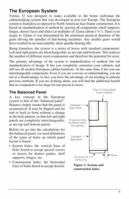
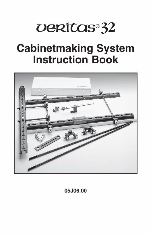
Figure 1: System and
construction holes.
Standard Upper Panel
Standard Base Panel
37mm
Floor-to-Ceiling Panel (Tower Cabinet)
All system holes at 32mm center
line spacing.
Toe shown for clarity only.
3
The European SystemVeritas 32 was designed to make available to the home craftsman the cabinetmaking system that was developed in post-war Europe. The European system is frameless as opposed to North American face-frame construction. It is based on standardization of method by spacing all components (shelf supports, hinges, drawer faces and slides) at multiples of 32mm (about 11/4"). There is no magic to 32mm; it was determined by the minimum practical diameter of the gears driving the spindles of line-boring machines. Any smaller gears would have resulted in an unacceptably short spindle-bearing life.
Being frameless, the system is a series of boxes with standard components. Left and right panels are interchangeable, as are tops and bottoms. This reduces the number of different sized components and therefore the potential for error.
The primary advantage of the system is standardization of method, but not standardization of design. It lets you completely customize your cabinets, and still use all modern European cabinet hardware. At the same time, it lets you use interchangeable components. Even if you are a novice at cabinetmaking, you are not at a disadvantage; in fact, you have the advantage of not needing to unlearn previous methods. If you are working alone, you will fi nd the additional benefi t that no component is too large for one person to move.
The Balanced Panel
A key concept in the European system is that of the “balanced panel”. Balance simply means that the panel is symmetrical. It may be fl ipped end for end or back to front without a change in the hole pattern, so that left and right panels are completely interchangeable, as are top and bottom panels.
Before we go into the calculations for the balanced panel, we need defi nitions of the types of holes on which panel layout is based.
• System holes: the vertical lines of holes bored to accept special screws or inserts for drawer guides, shelf supports, hinges, etc.
• Construction holes: the horizontal lines of holes bored to accept dowels.
4
Although it should never be necessary to drill complete lines, with a hole every 32mm, we do the calculations as though that were the case. The length of a panel is calculated by adding the panel thickness to a multiple of 32mm. That is,
length = thickness + (32 К N)
where N is the maximum number of system holes that could be drilled in a single vertical line.
The width of a balanced panel is similarly calculated:
width = 74 + (32 К N)
where N is the maximum number of construction holes that could be drilled in a single horizontal line. The 74mm is twice (once for the front, once for the back) the 37mm bacic set from the edge for the vertical row of system holes, the required distance for all European cabinet hardware (hinges, drawer slides, etc.).
As an example, for a standard lower cabinet, approximately 24" or 610mm deep, the exact width from the formula would be either:
586mm = 74 + (32 К 16)
or
618mm = 74 + (32 К 17)
since either 16 or 17 holes would be the maximum that could be drilled.
Note that if melamine covered or plywood panels are used, the exposed edges must have some sort of edging applied. When cutting your panels, an allowance must be made for this. The balanced panel dimensions include any edge banding applied, thus its thickness should be accounted for when determining panel sizes.
The interchangeability of panels and the reduction of error in carrying out the boring of system and construction holes make the design effort required to achieve balance well worthwhile for the commercial cabinetmaker. However, your cutting must be absolutely accurate to attain balance. A panel that is half a millimetre out can mean trouble at assembly time.
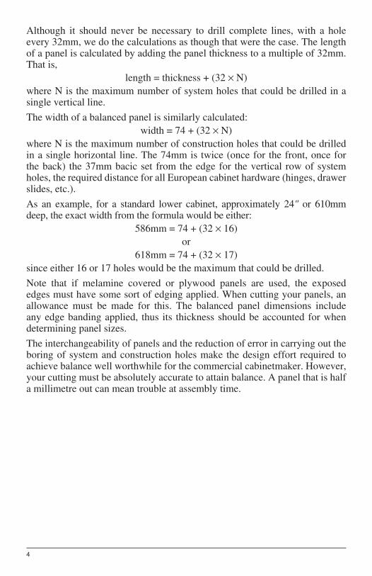
Reference Edge ( )
5
The Half-Balanced Panel
A more practical goal for the home cabinetmaker is the half-balanced panel. You can fl ip it end for end without changing the hole orientation, because its length is precise for balance, but not its width. This means that the same edge (the front edge), must always be used as the reference line for measurement.
The combined tolerances of Veritas 32 components will almost invariably be less important than your material tolerances when using the system. Off-the-shelf panels can vary substantially in width and occasionally in thickness. To eliminate (or at least make negligible) the errors this can introduce in your work, you can work to a reference edge. To keep track of reference edges, put an identifying mark on them. (Traditionally woodworkers have used a mark like this on such edges). Having done that, you should always then keep the clamp tails against this face. This will ensure that any variation in hole placement will always occur next to the non-reference edge (usually the back of the cabinet).
An exaggerated example is here shown:
If the adjustable clamp heads are kept to the top of the above panel, you will still end up with an accurately drilled set of construction holes and system holes.
If you use material of consistent width, this precaution is not necessary. Unfortunately, you usually fi nd out about inconsistent widths after you have cut and drilled a piece of stock so it is a good habit to use reference edges if you have any doubts.
Possible objections to the balanced panel arise from the fact that it does not produce countertops precisely 36" high or cabinet heights that perfectly fi ll the vertical space. These objections are easily met. Variation of a half inch in countertop height is of little signifi cance, and height should, in any case, depend on the height of the person working at the counter. Regarding total height, you will rarely fi nd a perfectly level ceiling, so some sort of molding is almost always essential to produce a smooth junction.
The half-balanced panel has advantages, especially if you are using solid wood facing to cover cut panel edges. Even if there are slight differences in thickness between strips of facing material, it should not cause you trouble, since any resulting variation in panel width shows up at the back, where it may be tolerated or, if too great, eliminated by trimming. Any minor inaccuracies at the back are hidden on the fi nished cabinet.
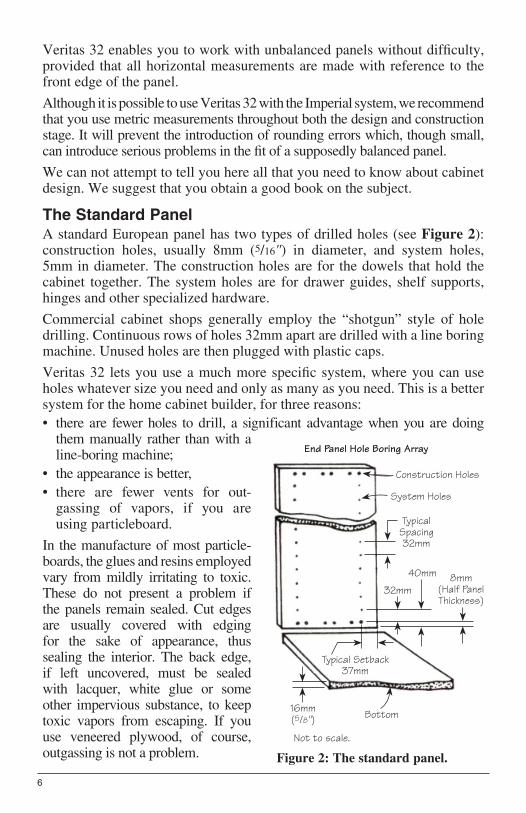
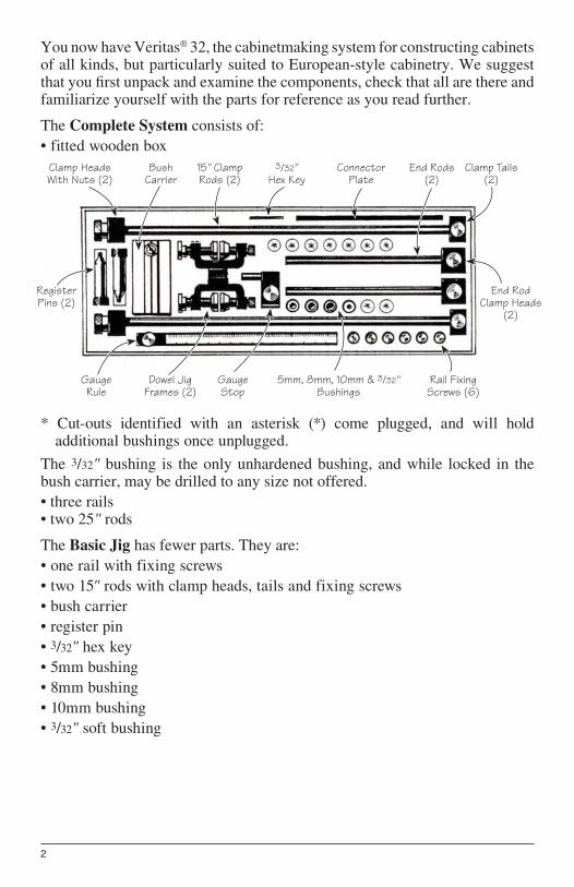
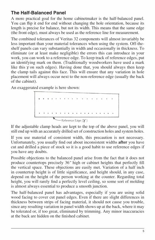
Figure 2: The standard panel.
Construction Holes
8mm (Half Panel Thickness)
Typical Setback37mm
System Holes
Bottom
Not to scale.
16mm(5/8")
Typical Spacing 32mm
32mm
40mm
End Panel Hole Boring Array
6
Veritas 32 enables you to work with unbalanced panels without diffi culty, provided that all horizontal measurements are made with reference to the front edge of the panel.
Although it is possible to use Veritas 32 with the Imperial system, we recommend that you use metric measurements throughout both the design and construction stage. It will prevent the introduction of rounding errors which, though small, can introduce serious problems in the fi t of a supposedly balanced panel.
We can not attempt to tell you here all that you need to know about cabinet design. We suggest that you obtain a good book on the subject.
The Standard Panel
A standard European panel has two types of drilled holes (see Figure 2): construction holes, usually 8mm (5/16") in diameter, and system holes, 5mm in diameter. The construction holes are for the dowels that hold the cabinet together. The system holes are for drawer guides, shelf supports, hinges and other specialized hardware.
Commercial cabinet shops generally employ the “shotgun” style of hole drilling. Continuous rows of holes 32mm apart are drilled with a line boring machine. Unused holes are then plugged with plastic caps.
Veritas 32 lets you use a much more specifi c system, where you can use holes whatever size you need and only as many as you need. This is a better system for the home cabinet builder, for three reasons:
• there are fewer holes to drill, a significant advantage when you are doing them manually rather than with a line-boring machine;
• the appearance is better,
• there are fewer vents for out-gassing of vapors, if you are using particleboard.
In the manufacture of most particle- boards, the glues and resins employed vary from mildly irritating to toxic. These do not present a problem if the panels remain sealed. Cut edges are usually covered with edging for the sake of appearance, thus sealing the interior. The back edge, if left uncovered, must be sealed with lacquer, white glue or some other impervious substance, to keep toxic vapors from escaping. If you use veneered plywood, of course, outgassing is not a problem.
Bush Carrier
Side Rails (2)
25" Rods (2)
15" Rods with Clamp Heads,
Nuts and Clamp Tails
(2)
Dowelling Jig Frames (2)
End Rods with Clamps and Screws
(2)
Fitted Wooden Box
Assembled Gauge Head
Register Pins (2)
Rail Fixing Screws (6)
Bushings
End Rail
Hex Key
Connector Plate
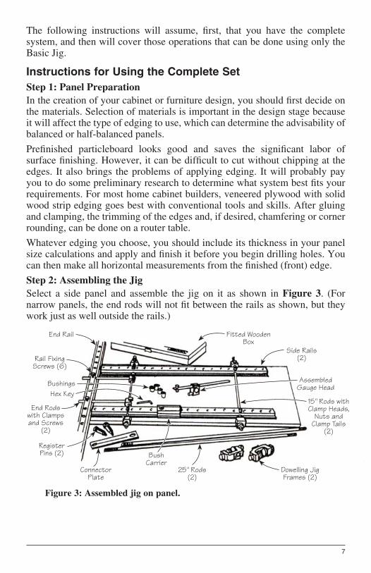
Figure 3: Assembled jig on panel.
7
The following instructions will assume, fi rst, that you have the complete system, and then will cover those operations that can be done using only the Basic Jig.
Instructions for Using the Complete Set
Step 1: Panel Preparation
In the creation of your cabinet or furniture design, you should fi rst decide on the materials. Selection of materials is important in the design stage because it will affect the type of edging to use, which can determine the advisability of balanced or half-balanced panels.
Prefi nished particleboard looks good and saves the signifi cant labor of surface fi nishing. However, it can be diffi cult to cut without chipping at the edges. It also brings the problems of applying edging. It will probably pay you to do some preliminary research to determine what system best fi ts your requirements. For most home cabinet builders, veneered plywood with solid wood strip edging goes best with conventional tools and skills. After gluing and clamping, the trimming of the edges and, if desired, chamfering or corner rounding, can be done on a router table.
Whatever edging you choose, you should include its thickness in your panel size calculations and apply and fi nish it before you begin drilling holes. You can then make all horizontal measurements from the fi nished (front) edge.
Step 2: Assembling the Jig
Select a side panel and assemble the jig on it as shown in Figure 3. (For narrow panels, the end rods will not fi t between the rails as shown, but they work just as well outside the rails.)
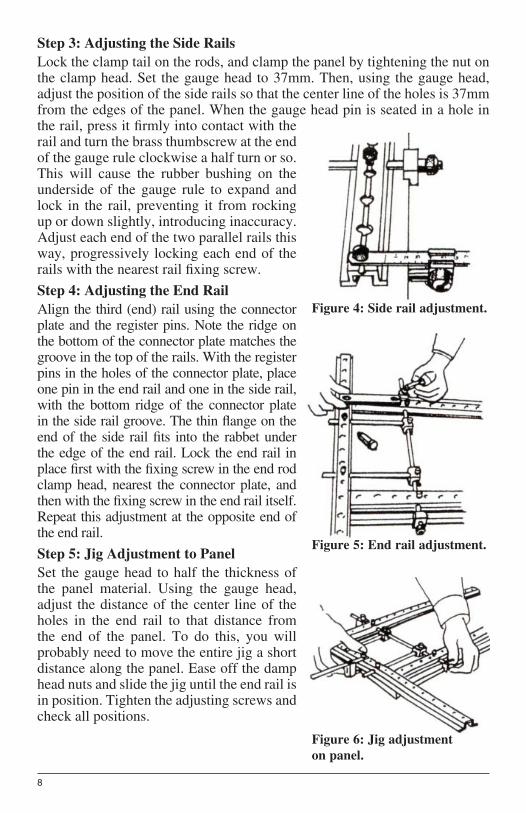
Figure 4: Side rail adjustment.
Figure 5: End rail adjustment.
Figure 6: Jig adjustment
on panel.
8
Step 3: Adjusting the Side Rails
Lock the clamp tail on the rods, and clamp the panel by tightening the nut on the clamp head. Set the gauge head to 37mm. Then, using the gauge head, adjust the position of the side rails so that the center line of the holes is 37mm from the edges of the panel. When the gauge head pin is seated in a hole in the rail, press it fi rmly into contact with the rail and turn the brass thumbscrew at the end of the gauge rule clockwise a half turn or so. This will cause the rubber bushing on the underside of the gauge rule to expand and lock in the rail, preventing it from rocking up or down slightly, introducing inaccuracy. Adjust each end of the two parallel rails this way, progressively locking each end of the rails with the nearest rail fi xing screw.
Step 4: Adjusting the End Rail
Align the third (end) rail using the connector plate and the register pins. Note the ridge on the bottom of the connector plate matches the groove in the top of the rails. With the register pins in the holes of the connector plate, place one pin in the end rail and one in the side rail, with the bottom ridge of the connector plate in the side rail groove. The thin fl ange on the end of the side rail fi ts into the rabbet under the edge of the end rail. Lock the end rail in place fi rst with the fi xing screw in the end rod clamp head, nearest the connector plate, and then with the fi xing screw in the end rail itself. Repeat this adjustment at the opposite end of the end rail.
Step 5: Jig Adjustment to Panel
Set the gauge head to half the thickness of the panel material. Using the gauge head, adjust the distance of the center line of the holes in the end rail to that distance from the end of the panel. To do this, you will probably need to move the entire jig a short distance along the panel. Ease off the damp head nuts and slide the jig until the end rail is in position. Tighten the adjusting screws and check all positions.
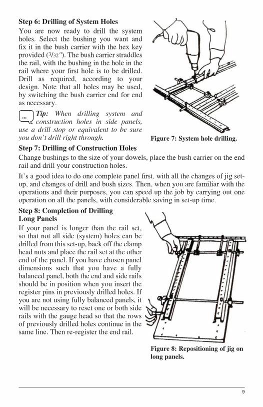
Figure 7: System hole drilling.
Figure 8: Repositioning of jig on
long panels.
9
Step 6: Drilling of System Holes
You are now ready to drill the system holes. Select the bushing you want and fi x it in the bush carrier with the hex key provided (3/32"). The bush carrier straddles the rail, with the bushing in the hole in the rail where your fi rst hole is to be drilled. Drill as required, according to your design. Note that all holes may be used, by switching the bush carrier end for end as necessary.
Tip: When drilling system and construction holes in side panels,
use a drill stop or equivalent to be sure you don’t drill right through.
Step 7: Drilling of Construction Holes
Change bushings to the size of your dowels, place the bush carrier on the end rail and drill your construction holes.
It’s a good idea to do one complete panel fi rst, with all the changes of jig set-up, and changes of drill and bush sizes. Then, when you are familiar with the operations and their purposes, you can speed up the job by carrying out one operation on all the panels, with considerable saving in set-up time.
Step 8: Completion of Drilling Long Panels
If your panel is longer than the rail set, so that not all side (system) holes can be drilled from this set-up, back off the clamp head nuts and place the rail set at the other end of the panel. If you have chosen panel dimensions such that you have a fully balanced panel, both the end and side rails should be in position when you insert the register pins in previously drilled holes. If you are not using fully balanced panels, it will be necessary to reset one or both side rails with the gauge head so that the rows of previously drilled holes continue in the same line. Then re-register the end rail.
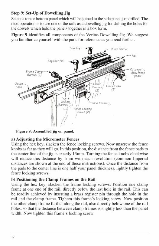
Figure 9: Assembled jig on panel.
Bush Carrier
Rail
Cutaway to show fence
pads.
Frame Locking
Screws (2)Fence Locking
Screws (2)
Fence Knobs (2)
Clamp Frames
(2)
Frame Clamp Screws (2)
Register Pin
Bushing
Gauge Head Fence Pads
(2)
10
Step 9: Set-Up of Dowelling Jig
Select a top or bottom panel which will be joined to the side panel just drilled. The next operation is to use one of the rails as a dowelling jig for drilling the holes for the dowels which hold the panels together in a box form.
Figure 9 identifi es all components of the Veritas Dowelling Jig. We suggest you familiarize yourself with the parts for reference as you read further.
a) Adjusting the Micrometer FencesUsing the hex key, slacken the fence locking screws. Now unscrew the fence knobs as far as they will go. In this position, the distance from the fence pads to the center line of the jig is exactly 13mm. Turning the fence knobs clockwise will reduce this distance by 1mm with each revolution (common Imperial distances are shown at the end of these instructions). Once the distance from the pads to the center line is one half your panel thickness, lightly tighten the fence locking screws.
b) Positioning the Clamp Frames on the RailUsing the hex key, slacken the frame locking screws. Position one clamp frame at one end of the rail, directly below the last hole in the rail. This can be readily achieved by inserting a brass register pin through the hole in the rail and the clamp frame. Tighten this frame’s locking screw. Now position the other clamp frame further along the rail, also directly below one of the rail holes, so that the distance between clamp frames is slightly less than the panel width. Now tighten this frame’s locking screw.
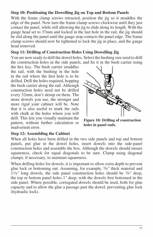
Figure 10: Drilling of construction
holes in panel ends.
11
Step 10: Positioning the Dowelling Jig on Top and Bottom Panels
With the frame clamp screws retracted, position the jig so it straddles the edge of the panel. Now turn the frame clamp screws clockwise until they just contact the panel, while still allowing the jig to slide along its length. With the gauge head set to 37mm and locked in the last hole in the rail, the jig should be slid along the panel until the gauge stop contacts the panel edge. The frame clamp screws should now be tightened to lock the jig in place, and the gauge head removed.
Step 11: Drilling of Construction Holes Using Dowelling Jig
You are now ready to drill the dowel holes. Select the bushing size used to drill the construction holes in the side panels, and fi x it in the bush carrier using the hex key. The bush carrier straddles the rail, with the bushing in the hole in the rail where the fi rst hole is to be drilled. Drill the holes required, hopping the bush carrier along the rail. Although construction holes need not be drilled every 32mm, don’t skimp on them. The more dowels you use, the stronger and more rigid your cabinet will be. Note that it is also useful to mark the rails with chalk at the holes where you will drill. This lets you visually maintain the pattern, without further calculation or inadvertent error.
Step 12: Assembling the Cabinet
When all holes have been drilled in the two side panels and top and bottom panels, put glue in the dowel holes, insert dowels into the side-panel construction holes and assemble the box. Although the dowels should ensure squareness, check for equal diagonals to be sure. Clamp using diagonal clamps, if necessary, to maintain squareness.
When drilling holes for dowels, it is important to allow extra depth to prevent glue lock or bottoming out. Assuming, for example, 5/8" thick material and 11/4" long dowels, the side panel construction holes should be 3/8" deep, the top or bottom panel holes 1" deep, with the dowels fi rst bottomed in the side panel. Where possible, corrugated dowels should be used, both for glue capacity and to allow the glue a passage past the dowel, preventing glue lock (hydraulic lock).
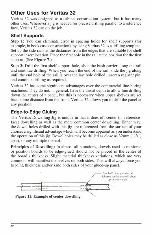
One half of any material thickness variations will show
up on each side.
Figure 11: Example of center dowelling.
12
Other Uses for Veritas 32Veritas 32 was designed as a cabinet construction system, but it has many other uses. Wherever a jig is needed for precise drilling parallel to a reference face, Veritas 32 can do the job.
Shelf Supports
Step 1: You can eliminate error in spacing holes for shelf supports (for example, in book case construction), by using Veritas 32 as a drilling template. Set up the side rails at the distances from the edges that are suitable for shelf support insert location. Place the fi rst hole in the rail at the position for the fi rst support. (See Figure 7.)
Step 2: Drill the fi rst shelf support hole, slide the bush carrier along the rail and continue drilling. When you reach the end of the rail, slide the jig along until the end hole of the rail is over the last hole drilled, insert a register pin, and continue drilling as required.
Veritas 32 has some signifi cant advantages over the commercial line-boring machines. They do not, in general, have the throat depth to allow line drilling down the center of a panel, but this is necessary when upper shelves are set back some distance from the front. Veritas 32 allows you to drill the panel at any position.
Edge-to-Edge Gluing
The Veritas Dowelling Jig is unique in that it does off-center (or reference-face) dowelling as well as the more common center dowelling. Either way, the dowel holes drilled with this jig are referenced from the surface of your choice, a signifi cant advantage which will become apparent as you understand the operation of this jig. Dowel holes may be drilled as close as 32mm (11/4") apart, or any multiple thereof.
Principles of Dowelling: In almost all situations, dowels used to reinforce or position boards to be edge-glued should not be placed in the center of the board’s thickness. Slight material thickness variations, which are very common, will manifest themselves on both sides. This will always force you to joint, thickness and/or sand both sides of your glued-up panel.
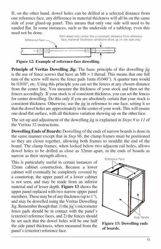
With dowel hole center line a constant distance from reference face, material thickness variations show up on one side only.Reference Face
Figure 12: Example of reference-face dowelling.
Reference Face
Side Panels
Figure 13: Dowelling ends
of boards.
13
If, on the other hand, dowel holes can be drilled at a selected distance from one reference face, any difference in material thickness will all be on the same side of your glued-up panel. This means that only one side will need to be sanded fl at. In some instances, such as the underside of a tabletop, even this need not be done.
Principle of Veritas Dowelling Jig: The basic principle of this dowelling jig is the use of fence screws that have an M8 К 1 thread. This means that one full turn of the screw will move the fence pads 1mm (0.040"). A quarter turn would be 0.010", etc. Using this principle you can set the fences at any chosen distance from the center line. You measure the thickness of your stock and then set the fences accordingly. If your stock is of consistent thickness, you can set the fences for center dowelling. Do this only if you are absolutely certain that your stock is consistent thickness. Otherwise, use the jig in reference to one face, setting it so that the dowel holes are approximately in the center of your work. This will ensure one dead-fl at surface, with all thickness variation showing up on the other face.
The set-up and adjustment of the dowelling jig is explained in Steps 9 to 11 of the Veritas 32 instructions.
Dowelling Ends of Boards: Dowelling of the ends of narrow boards is done in the same manner except that in Step 9b, the clamp frames must be positioned so they are closer together, allowing both frames to straddle the end of the board. The clamp frames, when locked below two adjacent rail holes, allows dowel holes to be drilled as close as 32mm apart, in the ends of boards as narrow as their strength allows.
This is particularly useful in certain instances of 32mm cabinet construction. Because a lower cabinet will eventually be completely covered by a countertop, the upper panel of a lower cabinet is not seen, and may be made from an inferior material and of lesser depth. Figure 13 shows the upper panel replaced with two narrow upper panel members. These may be of any thickness (up to 1"), and may be dowelled using the Veritas Dowelling Jig. Remember though that: 1) the jig’s micrometer fence pads should be in contact with the panel’s (exterior) reference faces, and 2) the fences should be set such that the dowel holes will be one half the side panel thickness, when measured from the panel’s (exterior) reference face.
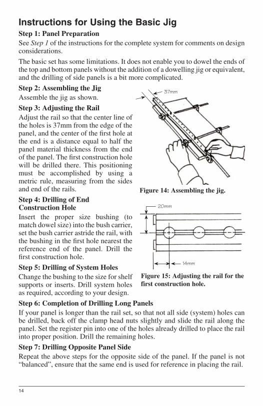
37mm
Figure 14: Assembling the jig.
20mm
14mm
Figure 15: Adjusting the rail for the
first construction hole.
14
Instructions for Using the Basic Jig
Step 1: Panel Preparation
See Step 1 of the instructions for the complete system for comments on design considerations.
The basic set has some limitations. It does not enable you to dowel the ends of the top and bottom panels without the addition of a dowelling jig or equivalent, and the drilling of side panels is a bit more complicated.
Step 2: Assembling the Jig
Assemble the jig as shown.
Step 3: Adjusting the Rail
Adjust the rail so that the center line of the holes is 37mm from the edge of the panel, and the center of the fi rst hole at the end is a distance equal to half the panel material thickness from the end of the panel. The fi rst construction hole will be drilled there. This positioning must be accomplished by using a metric rule, measuring from the sides and end of the rails.
Step 4: Drilling of End Construction Hole
Insert the proper size bushing (to match dowel size) into the bush carrier, set the bush carrier astride the rail, with the bushing in the fi rst hole nearest the reference end of the panel. Drill the fi rst construction hole.
Step 5: Drilling of System Holes
Change the bushing to the size for shelf supports or inserts. Drill system holes as required, according to your design.
Step 6: Completion of Drilling Long Panels
If your panel is longer than the rail set, so that not all side (system) holes can be drilled, back off the clamp head nuts slightly and slide the rail along the panel. Set the register pin into one of the holes already drilled to place the rail into proper position. Drill the remaining holes.
Step 7: Drilling Opposite Panel Side
Repeat the above steps for the opposite side of the panel. If the panel is not “balanced”, ensure that the same end is used for reference in placing the rail.
15
Step 8: Drilling of Intermediate Construction Holes
Since only the two extreme construction (dowel) holes have been drilled at the ends of the panel, place the rail in position across the end, registering it over those holes by means of the reference pin. Recall that the distance of the holes from the end is half the material thickness. If you are using thin material, a portion of the rail will overhang the edge. Support it with a piece of scrap stock. Drill the rest of the required construction holes.
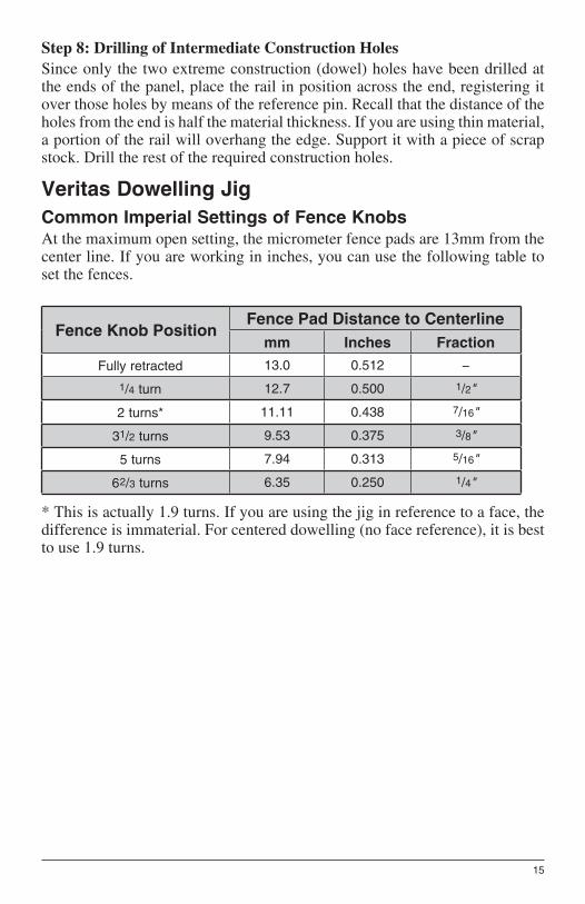
Veritas Dowelling Jig
Common Imperial Settings of Fence Knobs
At the maximum open setting, the micrometer fence pads are 13mm from the center line. If you are working in inches, you can use the following table to set the fences.
Fence Knob PositionFence Pad Distance to Centerline
mm Inches Fraction
Fully retracted 13.0 0.512 −
1/4 turn 12.7 0.500 1/2"
2 turns* 11.11 0.438 7/16"
31/2 turns 9.53 0.375 3/8"
5 turns 7.94 0.313 5/16"
6 2/3 turns 6.35 0.250 1/4"
* This is actually 1.9 turns. If you are using the jig in reference to a face, the difference is immaterial. For centered dowelling (no face reference), it is best to use 1.9 turns.

16
Dimensions in mm.
16 16 32 32 32 32 32
814 Proctor AvenueOgdensburg NY 13669-2205
United States
1090 Morrison DriveOttawa ON K2H 1C2Canada
[email protected]© Veritas Tools Inc. 2016 www.veritastools.com 126 IWE-001 Rev. A
Accessories
05J06.13 Rail, 208mm (83/16") with six holes spaced 32mm (11/4") apart, and a seventh intermediate hole centered between two 32mm spaced holes. Allows 16mm (5/8") center-to-center dowelling in the ends of boards as narrow as 22mm (7/8").05J06.12 Bush Carrier05J06.06 Register Pin05J03.15 Pair Long Rods05J03.30 Pair Extra-Long Rods 05J06.10 Gauge Head05J06.05 25" Rail with Two Fixing Screws05J06.07 Pair Connector Rods and 1 Plate05J06.14 Pair Dowelling Jig Bases
Bushings05J03.08 5mm05J03.09 6mm05J03.11 6.75mm05J03.12 7mm05J03.13 7.5mm05J03.18 8mm (5/16")05J03.21 9mm05J03.20 10mm05J03.22 3/32"*05J03.17 1/4"05J03.10 7/32"05J03.19 3/8"
* The 3/32" bushing is the only unhardened bushing, and while locked in the bush carrier, may be drilled to any size not offered.